Nc 5 Prezentare Eng
33
NC5 MANUAL
-
Upload
solomon-bogdan-daniel -
Category
Documents
-
view
214 -
download
0
Transcript of Nc 5 Prezentare Eng

N C 5 M A N U A L

3
Contents
Notes P. 04Main Menu Screen 0 P. 05Basics P. 06Function keys P. 07–08Step 1: Machine configuration Screen 83 Setup P. 09Step 2 User login P. 10Step 3: Central operator side Screen 22 Machine configuation P. 11Step 4: Load mould data Screen 45 Mould catalogue P. 12Step 5: Set sequences Screen 18 Machine operation P. 13
Set mould sequences Screen 16 Mould operation P. 14Step 6: Set mould Screen 10 Mould P. 15–16Step 7: Mould protection Screen 120 Mould protection P. 17Step 8: Set ejectors Screen 11 Ejectors P. 18Step 9: Set cores Screen 14 Cores P. 19
Screen 16 Mould sequence P. 20Step 10: Setting up injection unit Screen 30 Temperatures P. 21
Screen 31 Hot runner P. 22Screen 23 Injection unit P. 23Screen 20 Process optimisation P. 24Screen 26 Injection profile P. 25
Step 11: Process monitoring Screen 50 PDA statistics P. 26–27Screen 50 Actural value selection P. 28
Step 12: Process control Screen 52 Process control P. 29Step 13: Production Screen 54 Production data P. 30Step 14: Machine switch-off Screen 44 Switch-off matrix P. 31User-Parameter 1 Screen 222 P. 32User-Parameter 2 Screen 322 P. 33
NC5 Manual

4
Notes
This manual is designed to assist operators in setting up the machine. Initially, the basic functions will be explained. This is followed by a detailed description ofthe individual steps in setting up a mould through to production.
General notes on operation
Active input field (set value)
Inactive input field (set value);Dependent on sequence and program switch
Actual value (no entry possible)
Activated program switch
Active function group
Set position reached
NC5 Manual

5
Main Menue (Screen 0)
Help functionPrintScreen No.
ContentsUser-defined screenPassword
Configuration
Process
Production
Maintenance
Periphery
Alarms
Notes
Date and time
Screenforward
Softkey
Screenbackwards
Machinesequence
Mouldsequence
Alarm field Cycle sequenceNote field
NC5 Manual
Input field

6
Basics
• Function group Machine configuration with machine-specific functions, such as start-up and switch-off program, switch-off matrix and alarm reactions
• Function group Process with process-specific functions, such as temperatures at clamp and injection ends, process, and mould catalogue
• Function group Production with production-specific functions, such as process data acquisition, statistical process control, and reject segregation
• Function group Maintenance with maintenance-specific functions, such as diagnosis, putting into operation alarms, and events
• Function group Periphery with periphery-specific functions, such as Robot and Euromap 67
Note: Clicking on the function group will bring up the screen by the user;On clicking again (or double-clicking), the start screen of this particularfunction group will appear.
• User-defined screen is a customised screen defined by the user; selection is in screen 83 (Setup)
• Mould and Machine Sequences define sequences for cores, ejectors, valves (for descriptions see screens 16 and 18)
• Note field displays events that will not cause machine to be shut down
NC5 Manual

7
Process Injection unit Statistics Maintenance Periphery Printer
Clamping unit ProductionTemperatures Alarms Robot Password
SO(customisedoptions)on/off
Cylinder heateron/off
Hot runneron/off
Full-auto-mould
Semi-auto-mould
SettingPumpon/off Hand-operated
Sprue picker/Robot
Function keys
Sprue picker/Robot Set-stop on/off
NC5 Manual
Steppedoperation
Referenceposition

8
Mouldopen / close
Hydraulic ejectorback / forward
Coreextend / retract
Clamping elementsrotary platenextend/retract
Rotary platen centeringextend/retract
Rotary platenanti-clockwise/clockwise
Injection unit 1forward / back
Screw 1forward / back
Screw 1meter
Injection unit 1forward/back
Screw 1forward/back
Screw 1meter
Function keys
NC5 Manual

9
2) Enable touch input Click once (checkmark)
3) Input field Click once (green means activated)
4) Start page recommended start page is page 22 (any other page is also possible)
1) Touch control on/off (click on hand symbol)
Step 1: Machine configuration
(Screen 83/Setup)
NC5 Manual

10
1) LoginClick on key symbol
2a) Input by keyboard Enter password
or
2b) USB stick Insert USB steck and user will be indentified automatically
Step 2: User login
NC5 Manual

11
Process overviewwithout details(Profiles are only shownon level 1)
Navigate to:MouldEjectorProductionInjectionInjection unitTemperaturesProfiles
Profilesare displayedactive/inactive
Set reference position andejector zero point
Ejector and dry cycleon/off
Step 3: Central operators side
Machine configuration (Screen 22)
NC5 Manual

12
1) Select data selected data is marked in blue
2) Click on load (green means activated)
3) Component selection opens, select and confirm by clicking ‘Yes‘
Step 4: Load Mould Data
Mould Catalogue (Screen 45)
NC5 Manual
13
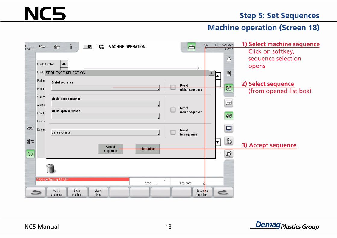
1) Select machine sequence Click on softkey, sequence selection opens
2) Select sequence (from opened list box)
3) Accept sequence
Step 5: Set Sequences
Machine operation (Screen 18)
NC5 Manual

14
1) Mould total sequence Click on softkey, Selection window opens
2) Select sequence Select ‘mould close‘ sequence and ‘mould open‘ sequence from predefined sequences
3) Accept sequence
Step 5: Select Mould Sequence
Mould Sequence (Screen 16)
NC5 Manual

15
1) Set mould height After installing mould, move mould to contact platens in setup mode, then clicking on switch; (mould height will be accepted, mould actual position will be ‘0‘ mm)
2) Enter speed Select speed level (are marked in green), enter speed and path points
3) Mould options Enter pressure and speed in setting mode
Step 6: Set mould (hydr. machine)
Mould (Screen 10)
NC5 Manual

16
1) Set clamping force Set toggle to desired clamping force using ‘mould height adjustment‘ buttons and lock ‘start‘ position
3) Mould options Select pressure and speed in setting mode
Step 6: Set Mould (toggle machine)
Mould (Screen 10)
NC5 Manual
2) Enter speed Select speed level (are marked in green) Enter speed and path points

17
1) Select basic monitoring
2) Select safety force and basic monitoring Enter safety force and positions for start and end of monitoring. Close and reopen mould
3) Select curve Enter safety force and position for end of curve monitoring
4) Store curve Close mould again. This will cause protective curve to be stored
Step 7: Mould Protection
Mould protection (Screen 120)
NC5 Manual

18
1) Click on ‘ejector‘ program switch (green means activated)
2) Set zero point Click on action switch; this will set ejector position at ‘0‘.
3) Set ejector Positions, pressures, and speed for extension and retraction
Step 9: Set ejectors
Ejector (Screen 11)
NC5 Manual

19
1) Click on ‘Cores‘ program switch (green means activated)
2) Set core pullers Enter pressure and speed
Step 9: Set Cores
Cores (Screen 14)
NC5 Manual

20
2) With standard sequence selected, the function mode will appear in blue direction arrow
3) Dynamic Softkey The softkey will bring up the screen associated with the marked symbol (e.g. Screen 14 – Cores)
1) Select core pull sequence Select standard sequences for ‘mould open and mould close‘.
Step 9: Set cores
Mould sequence (Screen 16)
NC5 Manual

21
1) Select mode Set all heating zones to ‘Control‘ (for further modes, see operating instructions)
2) Enter set values and tolerances
4) Oil preheating Activate by clicking
3) Synchronous heating On starting heating, all zones of the same temperature level will be controlled to set value.
Step 10: Setting up of Injection Unit
Temperatures (Screen 30)
NC5 Manual

22
2) Name individual zones
5) Boost function During start-up, selected zones may be varied for an adjustable time to a boost temperature.
1) Click on ‘hot runner‘ program switch
4) Enter set values and tolerances
3) Select mode Set all heating zones to control (for further modes, see operating instructions)
Step 10: Setting up of Injection Unit
Hot Runner (Screen 31)
NC5 Manual

23
3) Select function of IU
2) Set reference position of IU Advance IU with mould locked in setting-up mode and click on switch
4) Set IU Set values for speed, pressure and position for advance and retraction
1) Click on ‘Injection unit‘ program switch
Step 10: Setting up of Injection Unit
Injection Unit (Screen 23)
NC5 Manual
24
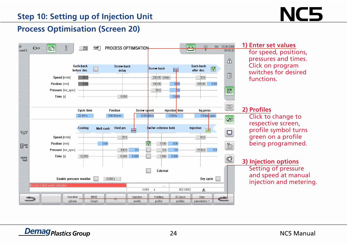
2) Profiles Click to change to respective screen, profile symbol turns green on a profile being programmed.
1) Enter set values for speed, positions, pressures and times. Click on program switches for desired functions.
3) Injection options Setting of pressure and speed at manual injection and metering.
Step 10: Setting up of Injection Unit
Process Optimisation (Screen 20)
NC5 Manual

25
2) Injection phase is shown inside the two blue lines
1) Enter set points for speed, positions and pressures (with pressure-limit profile activated)
Step 10: Setting up of Injection Unit
Injection Profile (Screen 26)
NC5 Manual

26
Display of thelast 15 cycles
Freeze imageOn clicking on camera,Values on screen are Bildfrozen, but actual valuescontinue to be recorded inbackground. On settingaction switch to 'inactive‘‚(grey), values are updated.
Selection menu:The mean values of theactivated parameters areaccepted as set values inprocess control.
Shot counterGreen indication: allparameters monitoredare within tolerance.Red indication: there isat least one parameterout of tolerance. Thevalue of the parameterIs shown in red.
Step 11: Process Control
Process Control Statistics (Screen 50)
NC5 Manual

27
Step 11: Process control
Process control statistics (Bild 50)
NC5 Manual
Transfer set value
Activate all
Disable all
1) Activate standard transfers all parameters
2) Delete calculation
Activate allAfter 20-50 shotsall parameters willtransfered forprocess control.
Unchanged set value
Transfer set valueCurrent averageswill be transfered asset values to processcontrol.

28
1) Selection of parameters In the first 16 columns parameters can be individually selected. To do so, click on black triangles and select desired parameter.
Step 11: Process control
PDA Actual Value Selection (Screen 50)
NC5 Manual

29
1) Activating the parameters to be monitored
2) Input tolerances Enter tolerances relative to set value.
3) Enter number of permissible deviations
4) Enter number of cycles to be monitored
5) Click on ‘tolerance deviation‘ program switch
Step 12: Process control
Process Control (Screen 52)
NC5 Manual

30
1) Enter order data Data on order, material and article can be entered here.
2) Enter total of good parts
3) Start of production Clicking on ‘Reset counter‘ causes cycle counter and number of parts produced to be reset. Clicking on ‘Reset all‘ causes set values for cavities, shotweight, total parts, boxes and pallets to be set at ‘0‘.
Step 13: Production
Production Data (Screen 54)
NC5 Manual

31
1) Select events and components Click on appropriate program switch
2) Enable by clicking on switch-off events required
3) Set cycle time monitor and switch-off delay
4) Click on switch-off matrix
Step 14: Machine Switch-off
Switch-off Matrix (Screen 44)
NC5 Manual

32
1) Select parameter Click on action switches and select parameter. If any line is to be unassigned, use the ‘FREE‘ parameter.
The screens „UserParameter 1-4“ permitparameter selectionto be customised.
User Parameters 1 (Screen 222)
NC5 Manual

33
1) Select parameter Click on action switches and select parameter. If any line is to be unassigned, use the ‘FREE‘ parameter.
The screens ‚UserParameter 1–4‘ permitparameter selectionto be customised.
User Parameters 2 (Screen 322)
NC5 Manual

Demag Plastics Group
Demag Ergotech GmbHAltdorfer Straße 1590571 SchwaigGermany
Telefon + 49 911 5061-0www.dpg.com


![Prezentare RIS ADR SM Timisoara.ppt ENG RIS_ADR SM_Timisoara.pdf · Microsoft PowerPoint - Prezentare RIS_ADR SM_Timisoara.ppt_ENG [Compatibility Mode] Author: cristian.gotia Created](https://static.fdocuments.in/doc/165x107/5fb5104175b06921d4491ad0/prezentare-ris-adr-sm-eng-risadr-smtimisoarapdf-microsoft-powerpoint-prezentare.jpg)