NAWCC EDUCATION COMMITTEE · NAWCC Education Committee 1 The Construction ... which are easily...
16
NAWCC Education Committee 1 The Construction of a Skeleton Clock NAWCC EDUCATION COMMITTEE
Transcript of NAWCC EDUCATION COMMITTEE · NAWCC Education Committee 1 The Construction ... which are easily...

NAWCC Education Committee 1
The Construction of a
Skeleton Clock
NAWCC EDUCATION COMMITTEE

NAWCC Education Committee 2
Preface The inspiration for this clock came to me as my son was moving out of his room to go to
college. After surveying his room I noticed the Soap Box Derby car that we had worked on when he was a young boy. I was reminded of the hours we enjoyed working together on the car. Then a thought came to me, “Why doesn’t the NAWCC have a project that could follow the same format as the Soap Box Derby?” Anyone could make the clock project, regardless of his or her clockmaking experience.
The skeleton clock was the result of many hours of drawing, making prototypes, and
consulting with my clock-collecting friends. I wanted this project to be one that could be done easily by the novice enthusiast and still have a fascination for the advanced horologist.
We hope that NAWCC chapters will use this project to increase chapter participation and to
increase membership. For those who wish to try this clock project, we encourage you to invite a son, daughter, grandson, granddaughter, or neighbor to share this experience with you. Let’s show them what a great organization we belong to!
Acknowledgments I thank all those who have assisted and given me the help and advice to design this skeleton
clock: Craig White of Milwaukee, WI, for aiding with the design of the clock (without Craig, this project would not have happened); my students at Milwaukee Area Technical College for taking on this project and making nine prototypes of this clock to prove that it can be done by both beginning and advanced students; and the NAWCC Education Committee for giving me the inspiration to continue to give our members more educational opportunities.
Michael Dempsey, FNAWCC
All rights reserved. No part of this publication may be reproduced, stored in a retrieval system or transmitted in any form or by any means electronic or mechanical or by photocopying or recording or otherwise without the consent of Michael Dempsey and the NAWCC Education Committee.
The information contained in this book is intended for NAWCC members only. Any other persons wishing to use the information and designs contained herein, for commercial gain, may not do so without the written permission of both Michael Dempsey and the NAWCC.

NAWCC Education Committee 3
Contents
• Section One: General Description ............................. 4
• Section Two: Tools .................................................... 5
• Section Three: Starting the Project ............................ 7 • • Section Four: Sawing................................................. 8
• Section Five: Filing.................................................... 9
• Section Six: Making the Posts .................................10
• Section Seven: Wheel Layout..................................11
• Section Eight: Click and Motion Works..................13
• Section Nine: Dial Plate and Posts ..........................14
• Section Ten: General Finishing ............................... 14
• Section Eleven: Lacquering / Wax Finish ...............15
• Section Twelve: Final Assembly .............................15

NAWCC Education Committee 4
Section One: General Description
Before we proceed with this project, it is very helpful for the person making this clock to have first taken the Field Suitcase Courses F101, F200, and F201. Even though this is not a prerequisite, it would make the clock project easier to do.
How could I expect someone to build a clock without some basic clockmaking skills? This
was a hard problem to overcome. I was walking around a mart room one day and noticed many old used Hermle movements for sale for next to nothing. It dawned on me if I could come up with a clock design to incorporate the gears and pinions of one of these movements, it could easily be made and with very little clockmaking skill. I selected a Hermle 341-020 with an 11-cm pendulum. I liked the small size, the number of gears, and the fact that the completed clock could fit under a glass dome and base, which are easily obtained through any clock supplier.
All the drawings that are needed to build this skeleton clock are in this book. The Cutting
Plate drawing gives the center marks for all the holes that need to be drilled for this project. Please do not photocopy this drawing and expect good results. This drawing is NOT a print but a plot from a plotting machine. No photocopy or scanner will give an exact layout of the center marks because these machines will distort the image slightly. Even a few thousandths of an inch will make the gears bind.
For the most part, all you need to do is cut and paste! The Cutting Plate Drawing is drawn to
scale. Cut the front and back plate out of the drawing and paste them to two sheets of brass and saw them out. No measuring or layout of the plates is necessary. The pillar posts are just straight brass bar stock and can be made to fit your tastes. The dial is printed for you. Use a dial cutter to cut it out and paste it to your clock. If you would like something different, you can purchase a dial through one of the clock suppliers.
I hope you enjoy making this clock as much as I have enjoyed putting this project together
for you. I have always been a strong voice in the NAWCC to increase educational opportunities for our members, and I can only hope with projects like this, we will continue to increase membership in our organization.
Michael Dempsey Chairman Education Committee
NAWCC Education Committee 5
Section Two: Tools
The tools needed for this project are very basic hand tools that are easily obtained. The only shop equipment that is needed is a drill press and a jeweler’s lathe.
• Jeweler’s Saw Frame: 2 dozen, #4/0 saw blades • Beeswax to lubricate the blade during cutting • Leather gloves • Pin vise • Caliper • Safety glasses • Scale or ruler • File card or Suede shoe brush (to clean files), chalk • Files: Shop or Flat Bastard files with handles (files must be sharp) 8" double cut,
8" flat single cut, and a 6" round taper • 2 “C” Clamps • Hammer: 4 oz. ball peen hammer • Center punch • Cutting broaches • Smoothing broaches • Set of numbered drills • #3 Center drill • Straight shank Reamer, .250" • Straight shank Reamer, .188" • Straight shank Reamer, .125" • Straight shank Reamer, .094" • Drill press • Jeweler’s lathe or a Micro Machine lathe with three-jaw chuck • X-acto knife • Chalk • 4/40 tap • 6/32 tap • 3/48 tap
Optional Tools • Depthing tool

NAWCC Education Committee 6
Material List • 4/40 x 3/16 slotted fillister machine screws, 8 pcs • 3/48 x 1/8 slotted fillister machine screws, 4 pcs • 6/32 x 3/16 slotted fillister machine screws, 6 pcs • 1/2″ brass round stock, 3″ long • 1/4″ brass round stock, 5″ long • 1/8″ brass round stock, 4″ long • Brass sheet 4″ x 6.5″ x .060 (1.5 mm) thick, 2 pcs • Brass sheet 4″ x 4″ x .060 (1.5 mm) thick, 1 pc • #3 flat washers • #6 flat washers • Hands from clock material dealer • Dome and base from clock material dealer • Spring pins 1/4″, 2 pcs • Spring pins 3/16″, 3 pcs • Hermle 341-020 11 cm
Special Tools • Sawing table can be purchased at (www.clockbug.com) • Center line gauge (www.mscdirect.com) #06410138
References www.btinternet.com/%7Ehognosesam/targets/targets1/drawfiling.htm
www.btinternet.com/~hognosesam/targets/targets1/drawfiling.htm

NAWCC Education Committee 7
Section Three: Starting the Project
Let’s get started! Cut two pieces of brass, 4″ x 6.5″ and .060 (1.5 mm) thick. Be careful not to scratch the brass. Find the Cutting Drawing Template from the pack of drawings. Use scissors to cut out the front and back plate separately. Cut around each drawing to about the same size as the brass pieces. Do not cut these on the outside black line. Leave the outside black line and follow it during the cutting process.
Clean each brass plate to remove grease or oil that might be on the plate. Using spray
adhesive, spray the brass plates and let the glue become tacky. When the glue has become tacky, carefully mount the paper templates to the brass plates. Be careful to eliminate any air pockets in the paper. (Using the edge of a plastic card helps to remove air pockets.) Set these aside to completely dry.
Before you begin sawing, on the FRONT PLATE, center punch all the pillar post center
holes, which are the green center marks, the DIAL CENTER marks, which are red and the blue center mark in the center of the plate. On the BACK PLATE, center punch the two blue center marks and the green center mark at the top of the drawing.

NAWCC Education Committee 8
Section Four: Sawing
Once the plates are dry it’s time to start sawing. This can be done one of two ways. I prefer to saw each plate separately, especially if you are new to this kind of work. Mount a cutting table in the vise, secure the plate, lubricate the blade with wax, and start sawing on the outside line. After the outside is cut, drill a .250 hole in each of the four quadrants of the body of the two plates and saw out the inside of each quadrant. Near the top of each plate is another area that needs to be sawed out. This is the window for the escape wheel and verge.
The second way would be to saw both plates at the same time. Start with the top post hole on
the front and back plate. Center punch the holes and spot drill them with a center drill. Use a #17 drill and drill through each plate. Use a .188 reamer and ream out the holes. After you have both top holes drilled and reamed, align the two plates and drive in a 3/16″ spring pin. Remember, you should have one cutting template on one side, and when you flip the assembly over, you should see the other cutting template. Clamp the plates together so they cannot pivot on the spring pin you just inserted. Center punch, center drill, drill, and ream the remainder of the pillar post holes and install spring pins in the reamed holes. The two bottom holes are drilled with a #1 drill and reamed with a .250 reamer. Use a 1/4″ spring pin in the two bottom holes. This will align both plates and secure them for sawing.
This project has plenty of excess stock so it’s almost impossible to make a mistake during the sawing operation.

NAWCC Education Committee 9
Section Five: Filing
If you have not already done so, drill and ream the plates as spelled out in the last section. Drive in the spring pins in the five pillar post positions to hold the plates together. Make sure that when you flip your plates over, you have a template on each side.
Start with a larger double cut file to file off any high or rough spots on the plates. When you
have completed this step, use a technique called “draw filing.” Draw filing will keep your edges nice and square. To draw file, use a single cut file, with one hand on the handle and the other on the end of the file. File perpendicular and flat to the filing surface. I designed this clock so that the radius of the body can also be draw filed with a flat file. When all the surfaces are smooth, take small strips of increasingly finer wet/dry sandpaper and wrap around the file to give the desired finish that you want. Notice in the pictures that the vise holding the plates has copper jaw caps. Take care to protect the plates from being scratched. Remember, any scratch you put in now will need to be removed later!
Do not remove the spring pins that are holding the plates together, yet!

NAWCC Education Committee 10
Section Six: Making the Posts
Make a total of eight posts for this clock: five pillar posts and three dial posts. The drawing calls for them to be made of brass, but almost any material may be used. I always thought that aluminum would make a great substitute and would give a great “two-tone” look. This is a great place to personalize your clock. Take some creative freedom with the finish of these posts if you wish. You may choose to add some sort of radius or curve to the outside of the posts. Remember, do not change the length of the post.
Review the enclosed drawing. Make sure you understand all the dimensions and hole
locations. Next, select the material, and cut to length. Put them one at a time into a three-jaw chuck and face off the material with either a cross slide or a graver. Find the center and drill to the drawing size specified. Tap each hole to the drawing specifications. Do not use any cutting fluid on nonferrous metals during the tapping and drilling process. After tapping, machine the boss (the diameter at the end of the post) on the end of the post. After this step has been completed, turn the material around and use the same procedure on the other end.
Remember, all of these posts need to be made to the same length to avoid the clock parts from twisting when assembled. The boss at the end of each post must fit tightly into the reamed holes on the plates to keep everything aligned.
Do not remove the spring pins that are holding the plates together, yet!
NAWCC Education Committee 11
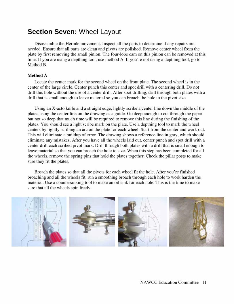
Section Seven: Wheel Layout
Disassemble the Hermle movement. Inspect all the parts to determine if any repairs are needed. Ensure that all parts are clean and pivots are polished. Remove center wheel from the plate by first removing the small pinion. The four-lobe cam on this pinion can be removed at this time. If you are using a depthing tool, use method A. If you’re not using a depthing tool, go to Method B. Method A
Locate the center mark for the second wheel on the front plate. The second wheel is in the center of the large circle. Center punch this center and spot drill with a centering drill. Do not drill this hole without the use of a center drill. After spot drilling, drill through both plates with a drill that is small enough to leave material so you can broach the hole to the pivot size.
Using an X-acto knife and a straight edge, lightly scribe a center line down the middle of the
plates using the center line on the drawing as a guide. Go deep enough to cut through the paper but not so deep that much time will be required to remove this line during the finishing of the plates. You should see a light scribe mark on the plate. Use a depthing tool to mark the wheel centers by lightly scribing an arc on the plate for each wheel. Start from the center and work out. This will eliminate a buildup of error. The drawing shows a reference line in gray, which should eliminate any mistakes. After you have all the wheels laid out, center punch and spot drill with a center drill each scribed pivot mark. Drill through both plates with a drill that is small enough to leave material so that you can broach the hole to size. When this step has been completed for all the wheels, remove the spring pins that hold the plates together. Check the pillar posts to make sure they fit the plates.
Broach the plates so that all the pivots for each wheel fit the hole. After you’re finished
broaching and all the wheels fit, run a smoothing broach through each hole to work harden the material. Use a countersinking tool to make an oil sink for each hole. This is the time to make sure that all the wheels spin freely.

NAWCC Education Committee 12
Method B Locate the center mark for the second wheel on your front plate. The second wheel center is
in the center of the large circle. Center punch this center and spot drill with a centering drill. Do not drill this hole without the use of a center drill. After spot drilling, drill through both plates with a drill that is small enough to leave material so you can broach the hole to the pivot size.
Using an X-acto knife and a straight edge, lightly scribe a center line down the middle of the
plates using the center line on the drawing as a guide. Go deep enough to cut through the paper but not so deep that much time will be required to remove this line during the finishing of the plates. You should see a light scribe mark on the plate.
On the Cutting Drawing Template the depthing dimensions are included. Use a Center Line
Gauge (MSC # 06410138) and a digital caliper. Please read the instructions that come with this gauge so you understand the principle here. Do some math calculations before you set the caliper. Refer to the last page of this publication for an example. Set the caliper to the required dimension and use the gauge to scribe an arc on the plates. The drawing shows a reference line in gray, which should eliminate any mistakes. After all the wheels are laid out, center punch and spot drill with a center drill. Drill through both plates with a drill that is small enough to leave material so that you can broach the hole to size.
Broach the plates so that all the pivots for each wheel fit the hole. After you have finished broaching and all the wheels fit, run a smoothing broach through each hole to work harden the material. Use a counter sinking tool to make an oil sink for each hole. This is the time to make sure you have end shake for each wheel and that all the wheels spin freely.
Remove the spring pins that hold the plates together and check the posts to make sure they fit
the plates.

NAWCC Education Committee 13
Section Eight: Click and Motion Works
We will be using the click spring, click retainer, click, ratchet wheel, intermediate wheel, and post of the old movement. After you have the movement assembled, put the ratchet wheel on the winding arbor. Using the click retainer as a template, scribe the hole location. Drill and tap the hole to hold on the retainer.
Find the click spring and click and use the same procedure to locate the holes for drilling and
tapping. You may choose to use the old rivet or make your own. You can change the click spring to something different out of one of the supplier catalogs.
Assemble the hour pinion on the center shaft. Put on the hour wheel over the center shaft.
Locate the intermediate wheel and depth this wheel by eye. The wheel should be located straight down the center line from the center wheel. Again make your own post or use the one from the old movement. Drill and broach the hole to size to allow for pressing in of the post.
This is the time when you drill and ream the three holes for the dial posts and drill and
tap the two holes on the back plate for the verge bridge.

NAWCC Education Committee 14
Section Nine: Dial Plate and Posts
Locate the drawing of the dial plate, dial, and dial posts. The dial plate drawing is made to the exact size needed. This procedure will be handled just like the movement plates. Cut out the dial plate from the drawing and glue it to a piece of brass. Center punch the three center marks for the dial posts. Begin sawing out the dial plate just like we did for the movement plates. When you have both the outside and the inside cut out, file and finish like the movement plates. Spot face with a center drill, drill and ream to the dimension on the drawing. Notice the small notch on the top of the dial plate. This is to assist in positioning the paper dial at the “12” position.
The dial posts are made like the movement pillar posts, but no drilling or tapping is required. When the dial plate and posts have been made, press the posts into the holes on the dial pan.
Make sure that the posts are flush with the dial plate. You may need to file this flat. Put this aside for now until we lacquer the whole clock.
As you can see by the drawing, a dial is included in the drawing. When you are finishing the
clock, you can use a dial cutter to cut out the dial and glue it to the dial plate.
Section Ten: General Finishing
Before any finishing work is done, I suggest that you assemble the clock and test run it for a few weeks to avoid any damage to the finish due to corrections.
The plates will be sanded to the desired finish by using different grits of sandpaper. If you
were very careful during this process, you can start with a medium to fine wet/dry sandpaper. Lay the plates flat on a hard surface and move them up and down only. You want the lines to move the length of the plates. Once you get down to a very fine paper, use cotton gloves to keep hand oils off the plates. I do not suggest using a machine like a power buffer on these plates. If the plate gets caught on the wheel, you will need to start over.
NAWCC Education Committee 15
Section Eleven: Lacquering / Wax Finish
This operation is totally up to the individual. When I built this clock for the first time, I chose the wax finish. I really prefer this to a high-gloss type of finish. To me it gives the clock an “older” look. Wax the plates, posts, and the dial plate, except the front of the dial plate, by using a high-grade automotive wax. Do not wax the front of the dial pan to avoid problems gluing the paper dial to a waxed surface.
Lacquering the clock will give you a finish that will last for a very long time. I always use a
high-grade automotive lacquer and lacquer thinner. I mix them in a gallon can, 80 percent thinner to 20 percent lacquer. My local automotive paint shop special mixes this for me. Mix these slowly. Once mixed, put toothpicks in all pivot holes and dip the parts into the container and hang them to dry. They will dry very quickly.
Section Twelve: Final Assembly
You should now be able to assemble the clock. After the clock is assembled, push the dial pan onto the front plate without the paper dial on. The dial is held on with just the friction of the fit into the holes. Cut out the dial with a dial cutter slightly larger than needed. Using rubber cement, glue the dial to the pan, lining it up by eye. I have included a small notch at the top of the dial pan to use as a reference point for the “12”. Remove the dial pan assembly and very lightly spray clear lacquer over the paper dial. This will protect the dial. Use an X-acto knife to trim the edges when the dial is dry.
This clock was designed to fit under a standard dome and base, which are available from
many of the clock material dealers.
NAWCC Education Committee 16
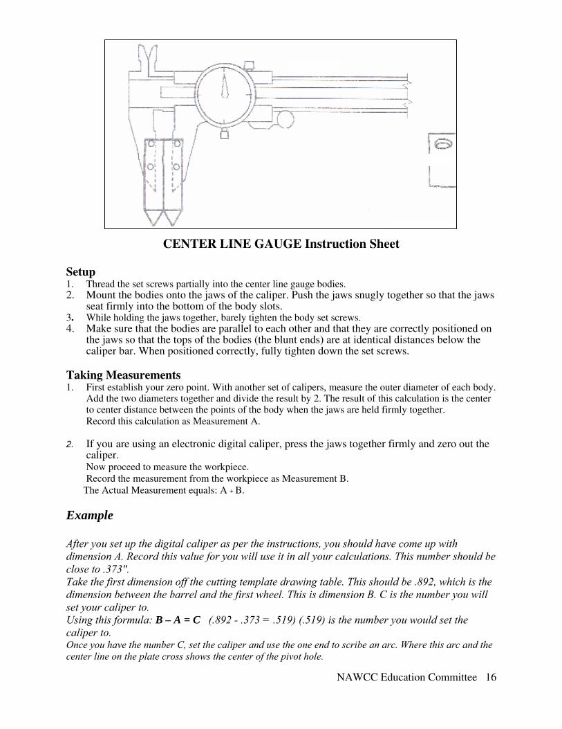
CENTER LINE GAUGE Instruction Sheet Setup 1. Thread the set screws partially into the center line gauge bodies. 2. Mount the bodies onto the jaws of the caliper. Push the jaws snugly together so that the jaws
seat firmly into the bottom of the body slots. 3. While holding the jaws together, barely tighten the body set screws. 4. Make sure that the bodies are parallel to each other and that they are correctly positioned on
the jaws so that the tops of the bodies (the blunt ends) are at identical distances below the caliper bar. When positioned correctly, fully tighten down the set screws.
Taking Measurements 1. First establish your zero point. With another set of calipers, measure the outer diameter of each body.
Add the two diameters together and divide the result by 2. The result of this calculation is the center to center distance between the points of the body when the jaws are held firmly together. Record this calculation as Measurement A.
2. If you are using an electronic digital caliper, press the jaws together firmly and zero out the
caliper. Now proceed to measure the workpiece. Record the measurement from the workpiece as Measurement B.
The Actual Measurement equals: A + B.
Example After you set up the digital caliper as per the instructions, you should have come up with dimension A. Record this value for you will use it in all your calculations. This number should be close to .373″. Take the first dimension off the cutting template drawing table. This should be .892, which is the dimension between the barrel and the first wheel. This is dimension B. C is the number you will set your caliper to. Using this formula: B – A = C (.892 - .373 = .519) (.519) is the number you would set the caliper to. Once you have the number C, set the caliper and use the one end to scribe an arc. Where this arc and the center line on the plate cross shows the center of the pivot hole.