NAVY - Under Secretary of Defense for Acquisition ...€¦ · Web viewSUBJECT/WORD INDEX TO THE...
80
NAVY Proposal Submission The responsibility for the implementation, administration and management of the Navy SBIR program is with the Office of the Chief of Naval Research. The Navy SBIR Program Manager is Mr. Vincent D. Schaper. Inquiries of a general nature may be brought to the Navy SBIR Program Manager's attention and should be addressed to: Office of the Chief of Naval Research ATTN: Mr. Vincent D. Schaper 800 North Quincy Street, BCT #1, Room 922 Arlington, VA 22217-5000 (703) 696-4286 SBIR proposals shall not be submitted to the above address and must be received by the cognizant activities listed on the following pages in order to be considered during the selection process. The Navy's mission is to maintain the freedom of the open seas. To that end the Navy employs and maintains air, land and ocean going vehicles and personnel necessary to accomplish this mission. The topics on the following pages represent a portion of the problems encountered by the Navy in order to fulfill its mission. The Navy has identified 82 technical topics in this second annual DOD Solicitation to which small R&D businesses may respond. This is approximately the same amount of topics normally identified by the Navy in the typical May DOD SBIR solicitation. The reduction of the total amount of topics is a reflection of the funding reduction the Navy has incurred in FY 1991/FY 1992 and expects similar funding constraints in FY 1992 and beyond. While the reduction in funds will not impact the Phase I awards that result from the topics listed in this solicitation, it makes it extremely important that Phase I award recipients influence the end uses of the technology since Phase II SBIR funds will be limited and thus highly competitive. Selection of proposals for funding is based upon technical merit and the evaluation criteria contained in this solicitation document. Because funding is limited the Navy reserves the right to limit the amount of awards funded under any topic and only those proposals considered to be of superior quality will be funded. Navy-1
Transcript of NAVY - Under Secretary of Defense for Acquisition ...€¦ · Web viewSUBJECT/WORD INDEX TO THE...

NAVY
Proposal Submission
The responsibility for the implementation, administration and management of the Navy SBIR program is with the Office of the Chief of Naval Research. The Navy SBIR Program Manager is Mr. Vincent D. Schaper. Inquiries of a general nature may be brought to the Navy SBIR Program Manager's attention and should be addressed to:
Office of the Chief of Naval ResearchATTN: Mr. Vincent D. Schaper800 North Quincy Street, BCT #1, Room 922Arlington, VA 22217-5000(703) 696-4286
SBIR proposals shall not be submitted to the above address and must be received by the cognizant activities listed on the following pages in order to be considered during the selection process.
The Navy's mission is to maintain the freedom of the open seas. To that end the Navy employs and maintains air, land and ocean going vehicles and personnel necessary to accomplish this mission. The topics on the following pages represent a portion of the problems encountered by the Navy in order to fulfill its mission.
The Navy has identified 82 technical topics in this second annual DOD Solicitation to which small R&D businesses may respond. This is approximately the same amount of topics normally identified by the Navy in the typical May DOD SBIR solicitation. The reduction of the total amount of topics is a reflection of the funding reduction the Navy has incurred in FY 1991/FY 1992 and expects similar funding constraints in FY 1992 and beyond. While the reduction in funds will not impact the Phase I awards that result from the topics listed in this solicitation, it makes it extremely important that Phase I award recipients influence the end uses of the technology since Phase II SBIR funds will be limited and thus highly competitive.
Selection of proposals for funding is based upon technical merit and the evaluation criteria contained in this solicitation document. Because funding is limited the Navy reserves the right to limit the amount of awards funded under any topic and only those proposals considered to be of superior quality will be funded.
Navy-1

NAVY SMALL BUSINESS INNOVATION RESEARCH PROGRAM
Submitting Proposals on Navy Topics
Phase I proposal (5 copies) should be addressed to:
AdministrativeTopic Nos. N92-107 through N92-114 SBIR Contact
Mail/Handcarry Address:
Office of Naval Research Dr. Donald PolkAttn: ONR Code 11SP, Room 804 (703) 696-4103SBIR Program, Topic No. N92-______800 N. Quincy Street, BCT #1Arlington, VA 22217-5000
Topic Nos. N92-115 through N92-167
Mail Address:
Commander Mr. John JohnsonNaval Air Systems Command (703) 692-7393Attn: Code AIR-05TE4, SBIR Program, Topic No. N92-______ Washington, DC 20361
Handcarry Address:
CommanderNaval Air Systems CommandAttn: Code AIR-05TE4, SBIR Program, Topic No. N92-______
1411 Jefferson Davis HighwayJefferson Plaza #1, Room 444Arlington, VA 22202
Topic Nos. N92-168 and N92-169
Mail Address:
Commander Mr. Donald WilsonNaval Surface Warfare Center (301) 394-1279White Oak LaboratoryAttn: Code R-05, SBIR Program, Topic No. N92-______Silver Spring, MD 20903-5000
Handcarry Address:
CommanderNaval Surface Warfare CenterWhite Oak LaboratoryAttn: Code R-05, SBIR Program, Topic No. N92-______Bldg. #1, Reception RoomSilver Spring, MD 20910
Navy-2

AdministrativeTopic Nos. N92-170 through N92-174 SBIR Contact
Mail Address:
Commanding Officer Ms. Carol Van WykNaval Air Warfare Center (215) 441-2375
Aircraft DivisionAttn: Code 094, SBIR Program, Topic No. N92______Warminster, PA 18974-5000
Handcarry Address:
Commanding OfficerNaval Air Warfare CenterAircraft DivisionAttn: Code 094, SBIR Program, Topic No. N92-______Street Road/Jacksonville RoadWarminster, PA 18974-5000
Topic No. N92-175
Mail Address:
Commanding Officer Mr. Pete O'Donnel Naval Air Warfare Center (908) 323-7566Aircraft Division LakehurstAttn: Code 02T (POD), SBIR Program, Topic No. N92-______Lakehurst, NJ 08733-5000
Handcarry Address:
Commanding OfficerNaval Air Warfare CenterAircraft Division LakehurstAttn: Code 02T (POD), SBIR Program, Topic No. N92-______Bldg. #342Lakehurst, NJ 07833-5000
Topic Nos. N92-176 through N92-179
Mail Address:
Commanding Officer Mr. Robert DobrowolskiNaval Air Warfare Center (609) 538-6754Aircraft Division TrentonAttn: Code PE 34, SBIR Program, Topic No. N92-______Trenton, NJ 08628-0176
Navy-3
AdministrativeHandcarry Address: SBIR Contact
Commanding OfficerNaval Air Warfare CenterAircraft Division TrentonAttn: Code PE 34, SBIR Program, Topic No. N92-______P.O. Box 7176Trenton, NJ 08628-0176
Topic Nos. N92-180 through N92-183
Mail Address:
Commander Mr. Daniel WattersNaval Air Warfare Center (301) 863-1144Aircraft DivisionAttn: Code CT222, SBIR Program, Topic No. N92-______Patuxent River, MD 20670-5304
Handcarry Address:
CommanderNaval Air Warfare CenterAircraft DivisionAttn: Code CT222, SBIR Program, Topic No. N92-______Bldg. #304Patuxent River, MD 20670-5304
Topic Nos. N92-184 through N92-186
Mail Address:
Commander Ms. Lois HerringtonNaval Air Warfare Center (619) 939-2712Weapons DivisionAttn: Code 004 (C002), SBIR Program, Topic No. N92-______China Lake, CA 93555-6001
Handcarry Address:
CommanderNaval Warfare CenterWeapons DivisionAttn: Code 004 (C002), SBIR Program, Topic No. N92-______515 Blandy Avenue, Annex A1China Lake, CA 93555-6001
Navy-4

AdministrativeTopic Nos. N92-187 and N92-188 SBIR Contact
Mail Address:
Commander Mr. Eugene PatnoNaval Air Warfare Center (805) 989-8801Weapons DivisionAttn: Code 3006, SBIR Program, Topic No. N92-______Point Mugu, CA 93042-5000
Handcarry Address:
CommanderNaval Air Warfare CenterWeapons Division Attn: Code 3006, SBIR Program, Topic No. N92-______
Bldg. 50, Room 1092Point Mugu, CA 93042-5000
Navy-5
SUBJECT/WORD INDEX TO THE NAVY SBIR 92.2 SOLICITATION
SUBJECT/WORD TOPIC NO.
ABAQUS........................................................................................................................................................... 184accelerators........................................................................................................................................................ 185acoustic............................................................................................................................... 110, 114, 126, 127, 150Acoustics.................................................................................................................................................... 114, 126ACT........................................................................................................................................................... 134, 175Active Control.................................................................................................................................................... 173actuator.............................................................................................................................................................. 174Advanced Concepts............................................................................................................................................ 133agent.................................................................................................................................................................. 139AI............................................................................................................................................................... 158, 183Air ASW ........................................................................................................................................................... 127Airborne Instrumentation................................................................................................................................... 181Aircrew....................................................................................................................... 121, 151, 152, 158, 159, 165Airflow....................................................................................................................................................... 148, 178Airflow Instrumentation..................................................................................................................................... 178airframe.............................................................................................................................................. 151, 152, 164algorithm............................................................................................................................................ 108, 150, 153algorithms............................................................................................113, 119, 126, 149, 150, 153, 159, 169, 172Amphibious........................................................................................................................................................ 129Anechoic Chambers........................................................................................................................................... 180antenna.............................................................................................................................................................. 180antennas............................................................................................................................................................. 180Anthropometric.................................................................................................................................................. 161Application Equipment...................................................................................................................................... 139architecture..........................................................................................................108, 113, 153, 157, 158, 169, 174array........................................................................................................................................................... 186, 188artificial intelligence................................................................................................................................... 158, 183ASW................................................................................................................................................... 126, 127, 150ATE................................................................................................................................................................... 121attack helicopter......................................................................................................................................... 151, 152Attrition............................................................................................................................................................. 147Augmentation.................................................................................................................................................... 174Automatic Trainer Test Procedures Guide..........................................................................................................183Autonomous flight operation & mission control.................................................................................................128avionics............................................................................................................................... 129, 135, 136, 140, 143
Ballistic Damage................................................................................................................................................ 151Ballistic Tolerance............................................................................................................................................. 151Beam.......................................................................................................................................................... 115, 186bearings...................................................................................................................................................... 115, 124BEM/FEM......................................................................................................................................................... 114BIT.................................................................................................................................................................... 137Broadband.......................................................................................................................................... 110, 126, 180
C3I..................................................................................................................................................................... 158Canopy Fracturing.............................................................................................................................................. 145Carrier Operations.............................................................................................................................................. 146chaff................................................................................................................................................................... 148chemical..................................................................................................................................................... 110, 175Chip Architecture............................................................................................................................................... 108
Navy-6

Chips.................................................................................................................................................. 108, 113, 149Chlorofluorocarbon (CFC)................................................................................................................................. 175Classification...................................................................................................................................... 113, 127, 150Clean Air Act..................................................................................................................................................... 175Close Combat..................................................................................................................................................... 129coating................................................................................................................................................ 125, 139, 141coatings.............................................................................................................................................. 125, 134, 139Cockpit........................................................................................................................................ 155, 161-164, 166Cockpit Display................................................................................................................................................. 164combustion......................................................................................................................................................... 178command and control.......................................................................................................................... 128, 154, 168Common Digital Electronic Modules................................................................................................................. 143communication................................................................................................................................... 128, 140, 179communications.................................................................................................................................. 140, 167, 180components....................................................110, 112, 119, 131, 134, 135, 137, 138, 142, 144, 155, 171, 177, 186composite......................................................................................................120, 123, 125, 133-135, 137, 140, 171composite materials............................................................................................................................ 123, 135, 171composite structures........................................................................................................................................... 133composites....................................................................................120, 123, 125, 133, 135, 136, 138, 140, 141, 171Computer Chip................................................................................................................................................... 113controls............................................................................................................................... 140, 161, 162, 173, 174Cooling.............................................................................................................................................................. 136Coordination............................................................................................................................................... 110, 158corrosion............................................................................................................................................. 111, 138, 141Cost Effectiveness...................................................................................................................................... 151, 152countermeasure.................................................................................................................................................. 169crack growth...................................................................................................................................................... 142Crack Initiation.................................................................................................................................................. 142crashworthiness.................................................................................................................................................. 152crashworthy design............................................................................................................................................. 152Criticality Analysis............................................................................................................................................ 116CRT Displays..................................................................................................................................................... 163cruise missile..................................................................................................................................................... 154cure cycle........................................................................................................................................................... 123
data acquisition.................................................................................................................................................. 181decision-making................................................................................................................................................. 146Degradable......................................................................................................................................................... 148Degradation......................................................................................................................... 108, 120, 138, 141, 159Design Influence................................................................................................................................................ 146detectors............................................................................................................................................................. 185Detonating Cord................................................................................................................................................. 145DI Simulation..................................................................................................................................................... 155diagnostic................................................................................................................................................... 111, 143Diesel Engine..................................................................................................................................................... 177Diesel Engines............................................................................................................................................ 176, 178DIFAR .............................................................................................................................................................. 126digital......................................................................................................................................... 137, 143, 159, 183display................................................................................................................................. 117, 162-164, 166, 179Display Controls................................................................................................................................................ 162displays........................................................................................................................ 117, 127, 161-164, 166, 179Distributed Computing....................................................................................................................................... 112Domain Model................................................................................................................................................... 157Doppler Shift..................................................................................................................................................... 170
Navy-7

ECCM................................................................................................................................................................ 172ECM.......................................................................................................................................................... 168, 172Ecology.............................................................................................................................................................. 175Ejection...................................................................................................................................................... 144, 145Ejection Sequencer............................................................................................................................................. 144Elastic Bodies.................................................................................................................................................... 114electromagnetic.......................................................................................................................................... 131, 140Electronic Countermeasures............................................................................................................................... 168electronic packaging................................................................................................................................... 135, 136electronic warfare....................................................................................................................................... 168, 180Embedded.................................................................................................................................................. 107, 140Enclosures.......................................................................................................................................... 135, 136, 184engine.......................................................................................................................................... 124, 125, 176-179Engine Air Filter................................................................................................................................................ 176engines........................................................................................................................................ 124, 125, 176-179Environment....................................120, 129, 131, 136, 140, 146, 150, 153, 156, 158, 160, 164, 166, 172, 180-181environmental degradation................................................................................................................................. 159Environmental Measurement.............................................................................................................................. 109Environmentally......................................................................................................................................... 122, 148Equipment Design.............................................................................................................................................. 179Escape........................................................................................................................................................ 139, 145expert system..................................................................................................................................................... 149Eye Point........................................................................................................................................................... 161
F-14................................................................................................................................................................... 115fabrication.....................................................................................................113, 125, 133, 134, 137, 144, 176-178Failure Detection................................................................................................................................................ 121Failure Modes Effects........................................................................................................................................ 116fatigue................................................................................................................................................. 123-125, 165Fault Coverage Metrics...................................................................................................................................... 143ferroelectric........................................................................................................................................................ 117Ferroelectric Liquid Crystal Displays ................................................................................................................ 117Fiber............................................................................................................................ 117, 120, 125, 148, 167, 171fiber optic.......................................................................................................................................................... 117fiber optics......................................................................................................................................................... 167Fibers.......................................................................................................................................... 125, 135, 140, 182field tests............................................................................................................................................................ 132filtration............................................................................................................................................................. 176Fire Damage...................................................................................................................................................... 171Flat Panel Conversion........................................................................................................................................ 166Flat Panel Displays.............................................................................................................................. 161-163, 166Flight..................................115, 128-129, 137, 140, 142, 153, 155-158, 161-162, 164-166, 173-174, 178, 181, 183flight control....................................................................................................................................... 173, 174, 183Flight Controls........................................................................................................................................... 161, 174Flight Simulation............................................................................................................................................... 157flight simulator................................................................................................................................................... 155Flightcrew.......................................................................................................................................................... 158FLIR.................................................................................................................................................................. 160Forecasting......................................................................................................................................................... 147fuel..................................................................................................................................................... 129, 139, 178Fuel Tank Coatings............................................................................................................................................ 139Fuel Tank Technology....................................................................................................................................... 139fusion................................................................................................................................................................. 153
Navy-8

Fuzzy Logic............................................................................................................................................... 149, 174
Galvanic............................................................................................................................................. 120, 138, 141gas turbine engines..................................................................................................................................... 124, 125glass................................................................................................................................................................... 171GPS.................................................................................................................................................................... 132Graphic Image Fusion........................................................................................................................................ 153graphics............................................................................................................................................................. 153Graphite.............................................................................................................................. 120, 123, 135, 138, 171Graphite/Epoxy Composites............................................................................................................................... 123grinding............................................................................................................................................................. 118
Halons Destruction............................................................................................................................................. 175Handling Characteristics.................................................................................................................................... 164Heads Up Display.............................................................................................................................................. 164heat damage....................................................................................................................................................... 171Heatsinks........................................................................................................................................................... 135helicopter..................................................................................................................... 128, 151, 152, 155, 156, 183Helicopter 3-D Airspeed..................................................................................................................................... 156Helicopter Aerodynamic Flow Field................................................................................................................... 156Helicopter Simulator Cue Requirements ............................................................................................................ 155Helicopter Simulator Fidelity............................................................................................................................. 155helmet mounted display..................................................................................................................................... 166HERO (Hazards of Electromagnetic Radiation to Ordnance)..............................................................................131high performance......................................................................................................... 120, 133, 135, 136, 140, 174high temperature................................................................................................................................................ 125HMD.................................................................................................................................................................. 166HUD........................................................................................................................................................... 160, 164Human Factors............................................................................................................................................ 161-163humidity............................................................................................................................................................. 137Hybrid Microelectronics..................................................................................................................................... 119Hydraulic Pump................................................................................................................................................. 121
identification............................................................................................................... 111, 119, 125, 160, 170, 172image compression............................................................................................................................................. 149image enhancement............................................................................................................................ 108, 127, 149image processing................................................................................................................. 108, 127, 149, 153, 169Imaging Systems................................................................................................................................. 108, 169, 185Imide/Graphite Composite................................................................................................................................. 120impact................................................................................................................................. 108, 123, 126, 127, 138IMU................................................................................................................................................................... 132Inflight Refueling Probe............................................................................................................................. 164, 165infrared........................................................................................................129, 159, 160, 168, 169, 182, 187, 188installation........................................................................................................................... 121, 127, 156, 165, 181instrumentation.............................................................................................109, 110, 156, 161-163, 166, 178, 181insulation........................................................................................................................................................... 141Integral Fuel Tank.............................................................................................................................................. 139Intercommunications System.............................................................................................................................. 167interference........................................................................................................................................................ 140interoperability................................................................................................................................................... 112IR................................................................................................................. 108, 149, 159, 168, 182, 187, 188, 188IR Image Processing........................................................................................................................................... 149IR/MMW Measurement..................................................................................................................................... 187ISAR.................................................................................................................................................................. 127
Navy-9

JIAWG....................................................................................................................................................... 137, 143JIAWG Diagnostic Initiative.............................................................................................................................. 143joints.................................................................................................................................................................. 111
Laminated Canopy............................................................................................................................................. 145laser.................................................................................................................................................... 156, 170, 186Laser Radar (LADAR)....................................................................................................................................... 170lasers........................................................................................................................................... 107, 169, 170, 182life cycle cost............................................................................................................................................. 146, 167Life prediction................................................................................................................................................... 124Limited Images.................................................................................................................................................. 182Liquid Penetrant Inspection................................................................................................................................ 122Load Alleviation................................................................................................................................................ 173Logistics Support Analysis................................................................................................................................. 116low cost............................................................................................................................... 109, 110, 118, 180, 186
machine intelligence.......................................................................................................................................... 174Machine Vision.......................................................................................................................................... 119, 127machining.......................................................................................................................................................... 123maintainability........................................................................................................................................... 116, 135maintenance..................................................................................................115, 116, 121, 138, 140-142, 146, 187manufacturing technology....................................................................................................118, 119, 133-135, 140Map............................................................................................................................................................ 137, 154Maritime............................................................................................................................................................ 129mass................................................................................................................................................................... 133Matched Filtering............................................................................................................................................... 126materials........................................................................118, 120, 122, 123, 134-136, 139, 141, 151, 171, 177, 186Matrix Addressable (FLC) Arrays...................................................................................................................... 117Measurement.......................................................................................................109, 110, 119, 123, 143, 178, 187measurement system.......................................................................................................................................... 187metal................................................................................................................................... 120, 135, 140, 141, 148metallic.............................................................................................................................................................. 142Millimeter Wave................................................................................................................................................ 187mine................................................................................................................................................................... 130Mines................................................................................................................................................................. 130Missile Domes................................................................................................................................................... 118missiles...................................................................................................................................................... 159, 168Mission Planning........................................................................................................................................ 153, 154model....................................................................................117, 128, 132, 146, 149, 155, 157, 159, 173, 174, 184modeling............................................................................................................................................. 125, 149, 184Montreal Protocol.............................................................................................................................................. 175MOVIESTAR.................................................................................................................................................... 184Multi-Sensor Integration.................................................................................................................................... 132
navigation.......................................................................................................................................................... 162Navy trainer Test Procedures Guide................................................................................................................... 183NDE................................................................................................................................................................... 123NDE Composites................................................................................................................................................ 123NDI.................................................................................................................................................................... 138neural network.................................................................................................................................... 108, 113, 128neural networks.................................................................................................................................................. 128Neutron Radiography......................................................................................................................................... 185Ni-alloy Corrosion............................................................................................................................................. 111
Navy-10

noise reduction................................................................................................................................................... 149non-acoustic....................................................................................................................................................... 127non-contact measurement................................................................................................................................... 119Non-Cooperative........................................................................................................................................ 170, 172Nonlinear Dynamics........................................................................................................................................... 107Nonlinear Optical Polymer................................................................................................................................. 186
Object Recognition............................................................................................................................................ 113OFT Testing....................................................................................................................................................... 183Optical..................................................................................................110, 117-119, 137, 140, 169, 170, 182, 186optical correlator................................................................................................................................................ 169Optical Disk....................................................................................................................................................... 137optical fibers ..................................................................................................................................................... 182Optical Fibers Coherent Imaging Diffraction......................................................................................................182optical processing............................................................................................................................................... 169Optics......................................................................................................................................... 107, 118, 167, 169optimization....................................................................................................................................................... 132packaging.................................................................................................................................... 135-137, 140, 148passive....................................................................................................................................................... 126, 187performance........................120, 122, 126-127, 133, 135-138, 140-141, 155, 165, 171-172, 174, 178, 180-181, 186periscope............................................................................................................................................................ 127Piezoelectric...................................................................................................................................................... 134Polishing............................................................................................................................................................ 118Polyamide.................................................................................................................................................. 138, 141polymer............................................................................................................................... 120, 133, 135, 140, 186Polymer Composite............................................................................................................................................ 120polymers............................................................................................................................................................ 186processing.....................................................................108, 120, 124, 126, 127, 134, 136, 140, 149, 153, 169, 172propulsion.................................................................................................................................... 124, 125, 175-179protocol.............................................................................................................................................................. 175
radar.................................................................................................................... 129, 160, 168, 170, 172, 180, 186RADHAZ........................................................................................................................................................... 131Radiated Environment........................................................................................................................................ 180radiation.............................................................................................................................. 107, 131, 168, 169, 184Radiation Hazard Primer.................................................................................................................................... 131Radiation Heat Transfer..................................................................................................................................... 184radiography........................................................................................................................................................ 185Real Time Radiography..................................................................................................................................... 185real-time..............................................................................................................108, 112, 127, 140, 169, 170, 185receivers............................................................................................................................................................. 110Reliability Centered Maintenance...................................................................................................................... 116Reliability Program............................................................................................................................................ 116Residual Stress Measurement............................................................................................................................. 123Reusability......................................................................................................................................................... 157REWRITABLE.................................................................................................................................................. 137RF...................................................................................................................................................... 169, 180, 188RF Transmitting Screen...................................................................................................................................... 188Ride Maneuver Control...................................................................................................................................... 173rotorcraft.................................................................................................................................................... 155, 183
SAR................................................................................................................................................................... 127SBIR............................................................................................................ 118, 132, 150, 153, 170, 173, 177, 189Scavenger ......................................................................................................................................................... 141
Navy-11

Seawater Pipe Corrosion.................................................................................................................................... 111seeker................................................................................................................................................................. 149SEM-E............................................................................................................................................................... 137semiconductor.................................................................................................................................................... 131semiconductor technology.................................................................................................................................. 131sensor....................................................................................109, 110, 119, 132, 134, 142, 156, 160, 172, 174, 187Sensor Based Manufacturing.............................................................................................................................. 119Sensor Interpretation.......................................................................................................................................... 160Sensor System............................................................................................................................................ 109, 142sensors.............................................................108-110, 113, 115, 119, 126-129, 132, 134, 140, 150, 160, 169, 182shallow water..................................................................................................................................................... 127Shipboard Landing Simulation........................................................................................................................... 155signal processing........................................................................................................................................ 126, 172Silicon carbide............................................................................................................................................ 125, 135simulation............................................................................................................. 128, 143, 155-157, 159, 173, 174simulator..................................................................................................................................... 121, 155, 180, 188simulators................................................................................................................................................... 158, 160SINDA............................................................................................................................................................... 184small engine....................................................................................................................................................... 177smart skins......................................................................................................................................................... 140Software...........................................112, 114, 116, 119, 126-127, 137, 139, 154, 157-158, 160, 174, 179, 183-184Spares ............................................................................................................................................................... 147spatial resolution................................................................................................................................................ 185Stability....................................................................................................................... 107, 125, 129, 133, 170, 174Stabilized Glideslope Displays........................................................................................................................... 117Statistical Process Control.................................................................................................................................. 119Steering.............................................................................................................................................................. 186Stratospheric Ozone Depletion........................................................................................................................... 175structural.......................................................................................................114, 123, 133, 138, 140-142, 171, 173Structural Vibration Control............................................................................................................................... 173structures..................................................................................................................................... 114, 133, 140-142Subcooled.......................................................................................................................................................... 136submarines......................................................................................................................................................... 126Substrates........................................................................................................................................................... 135supportability..................................................................................................................................................... 163survivability................................................................................................................................ 116, 129, 151, 152Survival............................................................................................................................................................. 144System Design............................................................................................................................ 108, 137, 146, 159System Engineering........................................................................................................................................... 116
T&E................................................................................................................................................................... 180tactical aircraft................................................................................................................................................... 133Tactical Cockpit................................................................................................................................................. 166Tactical Data.............................................................................................................................................. 163, 166Tactical Displays........................................................................................................................................ 161, 162target............................................................................................126, 127, 129, 132, 150, 160, 169, 172, 187, 188target recognition............................................................................................................................................... 169Target Screen..................................................................................................................................................... 188targeting............................................................................................................................................. 132, 160, 168Telemetry........................................................................................................................................................... 181TERCOM........................................................................................................................................................... 154Test....................................111, 115, 119, 122, 124, 135-137, 143, 150, 153, 155-156, 169, 172, 178-183, 185-188test facilities....................................................................................................................................................... 179test methods....................................................................................................................................................... 181
Navy-12

Thermal.................................................................................123, 125, 133, 135-137, 140, 160, 169, 171, 184, 185Thermal Analyzer.............................................................................................................................................. 184Thermal Damage................................................................................................................................................ 171Thermal Imagery................................................................................................................................................ 160Thrust................................................................................................................................................................ 144thrust vector control........................................................................................................................................... 144titanium.............................................................................................................................................................. 125TMG.................................................................................................................................................................. 184Tooling Concepts............................................................................................................................................... 133Tooling Improvement......................................................................................................................................... 133toxic................................................................................................................................................................... 175tracking...................................................................................................................................................... 159, 170trainers............................................................................................................................................................... 159training........................................................................................................................................ 153, 155, 157-160trajectory control................................................................................................................................................ 174transducer................................................................................................................................................... 134, 181transducers................................................................................................................................................. 134, 181transport............................................................................................................................................................. 137turbine engine.................................................................................................................................................... 124
UAV.................................................................................................................................... 128, 129, 168, 176-178unmanned aerial vehicle..................................................................................................................................... 129
V-22................................................................................................................................................................... 155validation............................................................................................................................................ 124, 174, 179Vector Control................................................................................................................................................... 144vehicles........................................................................................................................ 109, 110, 128, 168, 176-178verification.......................................................................................................................................... 143, 176-178VHSIC............................................................................................................................................................... 143video................................................................................................................................... 108, 153, 159, 169, 187Virtual........................................................................................................................................................ 158, 164vision.................................................................................................................................. 113, 119, 127, 145, 160VLSI.................................................................................................................................................................. 108VTOL................................................................................................................................................................ 129vulnerability....................................................................................................................................................... 151VX..................................................................................................................................................................... 160
warfare................................................................................................................. 127, 149, 153, 158, 167-169, 180Waste................................................................................................................................................................. 122water........................................................................................................................... 110, 120, 122, 127, 139, 160Water-borne....................................................................................................................................................... 122waveguide.......................................................................................................................................................... 186Wing Fold.......................................................................................................................................................... 115WST Testing...................................................................................................................................................... 183
Navy-13

DEPARTMENT OF THE NAVYINDEX OF NAVY TOPICS
OFFICE OF NAVAL RESEARCH
N92-107 TITLE: Nonlinear Dynamical Control of Lasers
N92-108 TITLE: Real Time Image Enhancement
N92-109 TITLE: Platforms for 4-Dimesional Environmental Sensing
N92-110 TITLE: 4-Dimensional Oceanographic Instrumentation
N92-111 TITLE: Remote Sensing of Crevice Corrosion
N92-112 TITLE: Module Interconnection Framework for Software Producibility
N92-113 TITLE: Object Recognition Chip (ORC)
N92-114 TITLE: Improved Methods for Predicting Acoustic Scattering from Submerged Elastic Bodies
NAVAL AIR SYSTEMS COMMAND
N92-115 TITLE: On Aircraft Analysis of F-14 Aircraft Wing Bearings
N92-116 TITLE: Failure Mode Effects and Criticality Analysis Integration Project
N92-117 TITLE: Matrix-Addressable Liquid Crystal Displays for Visual Landing Aids
N92-118 TITLE: Finishing of Optical Domes
N92-119 TITLE: High-Resolution Dimensional-Control-Sensors for Microelectronics Manufacturing Process
N92-120 TITLE: Imide/Graphite Composite Degradation Characterization
N92-121 TITLE: Aircraft Hydraulic Pump Condition Monitoring System
N92-122 TITLE: Penetrant Materials for Nondestructive Inspection
N92-123 TITLE: Residual Stress Measurement on Graphite/Epoxy Composites
N92-124 TITLE: Establishment of a New Rolling Contact Bearing Life Calculation Method
N92-125 TITLE: Fiber/Matrix Interphases for Silicon Carbide Fiber Reinforced Titanium Matrix Composites
N92-126 TITLE: Automatic Broadband Matched Filtering
N92-127 TITLE: SAR/ISAR Real Time Image Processing for Air ASW Platforms
N92-128 TITLE: Using Neural Networks for autonomous UAV flight operation and mission control
Navy-14

N92-129 TITLE: Vertical Takeoff and Landing Unmanned Aerial Vehicle for Maritime and Close Combat Applications
N92-130 TITLE: Improved Air-Developed Mines
N92-131 TITLE: 20MM Radiation Hazard(RADHAZ) Primer
N92-132 TITLE: Multi-Sensor Integration for High Altitude Bombing
N92-133 TITLE: Tooling Concept for the Fabrication of Large, Complex Composite Structures
N92-134 TITLE: In Situ Process Monitors for Composite Processing
N92-135 TITLE: Composite Material Electronic Enclosures and Circuit Module Heat Sinks/Substrates
N92-136 TITLE: Subcooled Liquid Change of Phase Thermal Management for Electronic Packaging
N92-137 TITLE: Military-Grade 3-1/2 inch Rewritable Optical Disk Drive
N92-138 TITLE: NDI Technique for Galvanic Degradation of Composites
N92-139 TITLE: Application Equipment/Software for Multi-Layer Fuel Tank Coatings
N92-140 TITLE: Composite Embedded Optical Fibers for Communication Links
N92-141 TITLE: Formulation of Effective Corrosion Scavengers
N92-142 TITLE: Localized Sensor System for Damaged Metallic Aircraft Structure
N92-144 TITLE: Improved Capability Electronic Ejection Sequencer (ICEES)
N92-145 TITLE: Innovative Design for Aircraft Canopy Fracturing System
N92-146 TITLE: Life Cycle Cost (LCC) Oriented for Naval Aircraft
N92-147 TITLE Spares Forecasting
N92-148 TITLE: Environmentally Degradable Chaff Packaging
N92-149 TITLE: Infra-red Image Processing Using Fuzzy Logic Expert System Technology
N92-150 TITLE: Air ASW Acoustic Classification
N92-151 TITLE: AH-1W Improved Ballistic Tolerance
N92-152 TITLE: AH-1W Improved Crashworthiness
N92-153 TITLE: Visualization and Analysis for Cruise Missile
N92-154 TITLE: Terrain Contour Matching (TERCOM) Map Placement
N92-155 TITLE: Minimum Simulation Cues Required for the Rotorcraft Shipboard Landing Task
Navy-15

N92-156 TITLE: Flight Test Instrumentation to Measure the Aerodynamic Flow Field of an H-60 Helicopter
N92-158 TITLE: "Virtual" Air Intercept Control (AIC) Architecture for Training Air Intercept Control Procedures
N92-159 TITLE: Environmental Degradation Model for Infrared Acquisition and Tracking
N92-160 TITLE: FLIR Training System
N92-161 TITLE: Determination of Actual Eye-point in the E-2C Cockpit
N92-162 TITLE: Determination of cockpit tactical display controls
N92-163 TITLE: Flat panel display technology for the E-2C Cockpit
N92-164 TITLE: Use of Heads Up Displays in the E-2C Cockpit
N92-165 TITLE: Long Duration Missions on the E-2C Aircraft
N92-166 TITLE: Use of Helmet Mounted Displays on the E-2C
N92-167 TITLE: Engineering Economy Analysis of an Intercommunication System Conversion for the E-2C
N92-168 TITLE: ECM Payloads for UAVs
N92-169 TITLE: Target Aim Point Selection Based on Real Time Optical Processing Visual or Infrared Generated Scenes
NAVAL AIR DEVELOPMENT CENTER
N92-170 TITLE: LADAR Identification (ID) Demonstration
N92-171 TITLE: Detection of Thermal Damage in Composite Materials
N92-172 TITLE: Aircraft Target Identification in an ECM Environment
N92-173 TITLE: Active Control of Fighter Maneuvers
N92-174 TITLE: Fuzzy Logic Applications to Flight Control
NAVAL AIR ENGINEERING CENTER
N92-175 TITLE: Disposal of Chlorofluorocarbon (CFC) Substances
NAVAL AIR PROPULSION CENTER
N92-176 TITLE: Innovative, Lightweight, And Sample Air Filtration Concepts For Small Displacement Diesel Engines
N92-177 TITLE: Innovative Unconventional Small Engine Concepts
Navy-16

N92-178 TITLE: Innovative Concepts for Directly Measuring Airflow In Intermittent Combustion Engines
N92-179 TITLE: Engine control via a standard 1553 bus controller for use at engine test facilities
NAVAL AIR TEST CENTER
N92-180 TITLE: Anechoic Chamber Radiated Environment
N92-181 TITLE: Wireless Airborne Instrumentation System
N93-182 TITLE: Infrared Optical Fibers
N92-183 TITLE: Artificial Intelligence (AI) Technology to Enhance Flight Test Software Configuration Control
NAVAL WEAPONS CENTER
N92-184 TITLE: Radiation Heat Transfer Analysis
N92-185 TITLE: Improved Thermal Neutron Imaging Method
N92-186 TITLE: Laser Beam Steering Via the Pockels Effect
PACIFIC MISSILE TEST CENTER
N92-187 TITLE: Dual Mode Infrared (IR)/Millimeter Wave (MMW) Measurement System
N92-188 TITLE: Multi-Spectral Scene Generation for Hardware-in-the-loop (HWIL) Laboratories
Navy-17

DEPARTMENT OF THE NAVYFY 1992 TOPIC DESCRIPTIONS
OFFICE OF NAVAL RESEARCH
N92-107 TITLE: Nonlinear Dynamical Control of Lasers
CATEGORY: Basic Research
OBJECTIVE: To obtain long term stability for the output of lasers via control techniques recently developed in the field of nonlinear dynamics.
DESCRIPTION: The physics of lasers, and solid state devices and their combination, naturally involves nonlinear dynamics. Instabilities, chaos, and spatio-temporal pattern formation and competition are common phenomena in regimes of nonlinear optics. Concomitantly, with an increased interest in the nonlinear dynamics of lasers there has arisen novel ideas for control of nonlinear systems. For example, these ideas involve stabilizing periodic orbits embedded in chaotic dynamics. Without control these periodic orbits are unstable. Phase I: Demonstrate the utility of control techniques developed in nonlinear dynamics for stabilizing lasers, especially for the generation of blue-green radiation via second harmonic generation from solid state lasers. Phase II: Apply the techniques developed in Phase I to lasers to achieve long term stability for operational applications.
N92-108 TITLE: Real Time Image Enhancement
CATEGORY: Basic Research
OBJECTIVE: To develop real-time systems, including VLSI chips, to solve the problems of noise removal, edge enhancement, dynamic range adjustment, uniformity correction, and color constancy in image sensors and systems.
DESCRIPTION: The problems of noise removal, edge enhancement, dynamic range adjustment, uniformity correction, and color constancy in imaging systems are extremely computation intensive tasks. These tasks cannot be done at the needed frame rate even with today's supercomputers. Recently there have been significant advances in using nearest neighbor interconnect type of architecture to solve the problems of real-time image processing. The silicon retina and color constancy work at Caltech, and the Cellular Neural Network work at the University of California readily come to mind. Research at numerous other universities, such as MIT Lincoln Laboratory and Johns Hopkins University can also be cited. It has been shown that these locally interconnected architectures, when realized on silicon, can perform real-time image processing with no degradation on the frame rate. Some small scale research prototype chips have been designed, and have demonstrated the potentials of the algorithm and architecture. There is no reason why full-scale system cannot be built to achieve real-time image enhancement. This would have significant impact on improving the image quality of civilian video, as well as military IR, systems. Phase I: Identify the research issues associated with developing full-scale VLSI chip or chips to achieve the stated objective, and to produce the conceptual design of a real-time image enhancement system. Phase II: Complete the detailed VLSI chip and system design, fabricate the system, and demonstrate the system to achieve the stated objective in real time.
N92-109 TITLE: Platforms for 4-Dimesional Environmental Sensing
CATEGORY: Basic Research
OBJECTIVE: To adapt available airborne/underwater remote operated vehicles to sensors for measuring 4-dimensional environmental parameters.
Navy-18

DESCRIPTION: Both Autonomous Underwater Vehicles (AUVs) and Remotely Operated Vehicles (ROVs) have been developed and used for specific applications such as location of opposition emplacements during Desert Storm. The increased emphasis on global climate change and the difficulty and expense in acquiring affordable 4-dimensional environmental sensing data strongly suggest application of low cost remotely operated vehicles for environmental parameter measurement. A vehicle/sensor system integration analysis is desired to identify the compatible measurements that are possible, the state of the art instrumentation required, the payload requirements versus mission, the power requirements and endurance, and the vehicle and control system description. Phase I: A description of the sensor/platform system, what would be measured, and why a remotely controlled platform is scientifically/fiscally superior to the present methods of making such measurements would be documented. Phase I should produce a report that identifies concepts that could be tested in Phase II. Phase II: Build the system identified in Phase I and demonstrate its predicted capabilities.
N92-110 TITLE: 4-Dimensional Oceanographic Instrumentation
CATEGORY: Basic Research
OBJECTIVE: To develop innovative instrumentation to measure oceanographic/meteorologic parameters.
DESCRIPTION: Innovative sensors/projectors and measurement techniques are solicited to obtain marine atmospheric, oceanographic (acoustical, optical, physical, biological, chemical, and geophysical) variables in 3D space and time. The emphasis is on (1) novel approaches and concepts for measuring multiple parameters coherently in 4D; (2) new methods of measuring fluxes, acoustic wavefields, or fluid motion of mixtures (i.e. water/bubbles/sediments/biologics). Instruments can be towed/tethered sensors/projectors, elements in arrays, or suites of instruments on ROVs(remotely operated vehicles) to cite a few examples. Low cost, reliable, and/or expendable sensors/projectors and components (e.g. broadband, large dynamic range, high efficiency, compact, low power consumption projector/receivers) are particularly desirable. Full depth capability is desired in instrumentation planned for subsurface use. Phase I: Provide a description of exactly what will be measured and to what accuracies and coherence as well as providing the design concept for achieving the measurements. Phase I should produce a proof of concept by demonstrating untested concepts or instruments. Phase II: Develop hardware and demonstrate feasibility in the laboratory. Field testing should be addressed via coordination with ongoing ONR field efforts. Potential approaches to industrial development that transition program output should also be outlined.
N92-111 TITLE: Remote Sensing of Crevice Corrosion
CATEGORY: Basic Research
OBJECTIVE: To develop a remote sensing technique to detect crevice corrosion.
DESCRIPTION: Crevice corrosion is a form of localized corrosion that can occur within crevices or at shielded surfaces where a stagnant solution is present. Crevices formed by the contacting surfaces of a gasket and a flange face in the presence of seawater have been particularly troublesome for the Navy in assembled seawater pipe networks where numerous gasketed junctions exist. The disassembling of pipe joints comprising gasketed flanges for crevice corrosion examination is tedious, difficult, and expensive. The ability to determine, without disassembling and inspection, whether crevice corrosion is occurring, or has occurred, within an assembled gasketed flange joint would be of great benefit to Navy operations. Phase I: Address remote sensing concepts for crevice corrosion which are capable of being developed into rapid diagnostic procedures. Phase II: The identified Phase I concept will be further developed and verified in simulated service situations using gasketed Ni-Cr-Mo-Fe alloys, such as Alloy 625, and chlorinated seawater, and a diagnostic procedure for the remote identification of crevice corrosion will be made available. The diagnostic procedure may comprise portable equipment, a test kit, or a service.
Navy-19

N92-112 TITLE: Module Interconnection Framework for Software Producibility
CATEGORY: Basic Research
OBJECTIVE: To develop a module interconnection framework for distributed applications programming.
DESCRIPTION: The great diversity of computing systems and software has created a major problem in the interoperability and integration of heterogenous systems and components. Recent research is exploring the technologies of open-system architectures, type theories, parameterized programming, real-time/fault-tolerant (RT/FT) systems theory, interconnection technologies, and module interconnection frameworks (MIF). These technologies facilitate the interconnection of systems and software components written in diverse source languages on networked architectures. Software producibility, usability and system evolution will be greatly improved through this important technology. Phase I: The objective is to design a MIF system for the development of software for distributed computing. The design should describe the mathematical semantics of the MIF, its capability to seamlessly compose software modules, its capability to handle abnormal events, its capability to manage RT/FT events, and its capability to analyze properties of systems built from MIFs. The use of the MIF should be illustrated through the development of the basic features of a distributed spread-sheet application. Phase II: An experimental research prototype based on the Phase I MIF design will be developed.
N92-113 TITLE: Object Recognition Chip (ORC)
CATEGORY: Basic Research
OBJECTIVE: Recent advances in multi-layer networks and "retina-like" silicon devices have made possible a new generation of sensors - i.e. chips that can recognize and/or classify objects. So-called "neural-network hybrid" systems may provide a method to accomplish this goal. At the minimum, an ORC should include "retinal" layers; a layer or circuit to deal with changes in the shape, scale, and rotation of the visual field; and a "classifier" circuit. The chip should work in real time and be programmable for different objects. Devices that propose to incorporate algorithms derived from biological systems (e.g. vision, pattern classification) are of special interest. Phase I: Address issues and concepts so as to demonstrate the feasibility of such a chip. This might include presenting a detailed architecture, specifications, and a schedule for prototype production. Phase II: Include design completion, fabrication, testing and debugging to produce a fully functional prototype.
N92-114 TITLE: Improved Methods for Predicting Acoustic Scattering from Submerged Elastic Bodies
CATEGORY: Basic Research
OBJECTIVE: To develop methods to overcome certain difficulties in applying boundary element/finite element methods to acoustic scattering from elastic bodies.
DESCRIPTION: The Navy has an interest in predicting acoustic scattering from submerged elastic bodies. Anticipated advances in computer capabilities will allow current structural-acoustic boundary element method-finite element method (BEM/FEM) techniques to be implemented at higher and higher frequencies. However, issues that are not necessarily solved by such advances and may limit prediction capability include the influences of damping, complex internal structures, appendages with small thickness-to acoustic wavelength ratios, and parameter uncertainties. ONR is interested in innovative approaches to some or all of the above issues that affect BEM/FEM structural acoustics predictions. Phase I: Demonstrate the criticality of a particular issue or set of issues and demonstrate the potential of a method or methods to address the issue or issues.
Navy-20
Phase II: Produce software implementing the method or methods from above into a full 3-D or semi-3-D BEM/FEM code.
NAVAL AIR SYSTEMS COMMAND
N92-115 TITLE: On Aircraft Analysis of F-14 Aircraft Wing Bearings
CATEGORY: Engineering Development
OBJECTIVE: To develop a test procedure which will identify faulty wing pivot bearings without removing the wing assemblies from the aircraft.
DESCRIPTION: This "on the aircraft" test will enable detection of faulty wing bearings as problems occur. The present method of replacing bearings on a set time schedule is not effective. Faulty bearings are not detected when they fail and many good bearings are replaced unnecessarily. Currently there is no way to test the wing pivot bearings without removing wings from the aircraft. When wing sweep causes excessive bearing noise, aircraft are routed to DEPOT for maintenance. In addition to the excessive maintenance cost of replacing good bearings, faulty bearings on operating aircraft could bind causing the race in the wing or box beam to rotate. Under dynamic flight conditions this could cause cracks in the box beam and result in safety-of-flight problems. Aircraft wing pivot bearings will be tested using the aircraft wing sweep functions as a low speed dynamometer. Either force detection sensors or tensiometer readouts could be used to measure the frictional forces as the wings are swept. Specifications for friction tolerances will be developed by empirical analysis on several F-14 aircraft or through theoretical analysis of aircraft loads. The Government will provide access to F-14 aircraft and the necessary ground support equipment to test the wing bearings. Phase I: Studies and experiments shall be performed to determine the feasibility of developing a comprehensive "on the aircraft" test of wing pivot bearing. Phase I shall provide a report which will include the analysis and relevant data to support the findings. Phase II: The objectives of this phase are to develop specifications for wing bearing friction and to develop the process and procedures for "on the aircraft" testing of wing pivot bearings. Prototype of ground support equipment required to perform the test will be developed during this phase.
N92-116 TITLE: Failure Mode Effects and Criticality Analysis Integration Project
CATEGORY: Engineering Development
OBJECTIVE: The project will create a tool to link the reliability program Failure Modes, Effects and Criticality Analysis (FMECA) to the logistics and related programs. The project will (1) develop a standard methodology for the analysis, and (2) develop software to automate and document the analysis. Benefits from standardizing and automating the analysis will be (1) standard definitions and processes, (2) earlier development of the data, (3) fewer person-hours required for the analysis, and (4) a common data base between the reliability and logistics programs.
DESCRIPTION: In Phase I, a step by step FMECA methodology for both a top down and bottom up approach shall be developed to provide a standard process for the analysis. Definitions and data requirements for the following programs shall be incorporated in the methodology: (1) Reliability & Maintainability, (2) Logistic Support Analysis, (3) System Safety, (4) Reliability Centered Maintenance (RCM), and (5) Survivability. In Phase 2, the contractor shall develop software that utilizes the methodology to perform and document a FMECA. The software shall be developed for an IBM personal computer and Vax computer. The software shall provide a process for performing a top down FMECA to the 5 digit work unit code and a bottom up FMECA starting at a piece part level and going up to the WRA/subsystem/system indenture level. The software will operate as a stand alone, relational data base, requiring no other software for operation. The software will be menu driven. All commands will be displayed on the screen. Help screens will be provided to explain software operation, data element definitions, data entry, and report generation.
Navy-21

N92-117 TITLE: Matrix-Addressable Liquid Crystal Displays for Visual Landing Aids
CATEGORY: Engineering Development
OBJECTIVE: To develop stabilized optical landing aids with no moving parts by implementing matrix addressable Ferroelectric Liquid Crystal (FLC) displays to produce a slot that will form the object for an optical system. If successful, this concept will eliminate mechanical/electrical drive systems on shipboard stabilized systems with fixed azimuth display angles (i.e., FLOLS and VSTOL OLS).
DESCRIPTION: The matrix liquid crystal display will be computer driven. The object, a rectangular slot .05 by 4 inches, formed by the display matrix must be capable of transmitting visible light. The matrix display will be placed between a light source and an optical lens system to produce a stabilized light bar that is projected into space to provide pilots a glideslope display. The matrix crystal display must be able to shift the slot (object) vertically +/- 2 inches, as well as rotate it +/- 25 degrees. Pixel spacing center-to-center must be less than .01 inches. A maximum frame rate of 90 Hz is required. Ship motion would be compensated for by changing the position of a light bar on a liquid crystal display matrix. The display matrix would be positioned behind a lens and would replace the moving fiber optic block concept now used in the VSTOL Program. Phase I: Should produce a final report outlining the approach undertaken to pursue the requirements above with sufficient data to demonstrate the feasibility of the concept. Phase II: Should use the approach outlined in Phase I to produce a working model that demonstrates the concepts outlined above and can be field tested at NAEC.
N92-118 TITLE: Finishing of Optical Domes
CATEGORY: Exploratory Development
OBJECTIVE: The objective of this work is to investigate the finishing processes used and to establish low cost techniques to obtain the required final product.
DESCRIPTION: The processes used are scooping, grinding, and polishing. The curvature, thickness, and surface finish are extremely critical to the utility of the domes. Sapphire is the primary application for this finishing process, however, the techniques developed would be applicable to all domes regardless of the basic materials used. These processes need to be defined in detail and their feasibility demonstrated. Certain cost drivers in the manufacturing of optical domes for missile systems have been addressed through SBIR and other programs. One area that has not been addressed is the finishing processes used to provide for the final configuration of domes. The costs of these processes remain high. Presently these costs can be more than 50% of the total cost of a dome. Phase I: Develop and provide a proposed Phase II program plan to develop a working prototype system to finish sapphire domes. Phase II: Develop and demonstrate a prototype system to finish sapphire domes and provide a specified number of finished domes.
N92-119 TITLE: High-Resolution Dimensional-Control-Sensors for Microelectronics Manufacturing Process
CATEGORY: Exploratory Development
OBJECTIVE: To develop high resolution sensors for dimensional measurement of microelectronic circuits and components. Measurement data can be used in closed-loop process control algorithms for guidance, alignment, and inspection. Successful achievement of this project will create a high speed, high resolution, non-contact measurement (monitoring) technique (system), which assures quality consistencies among weapon systems, and eliminates tedious manual inspection and repair efforts.
DESCRIPTION: Production yield and hardware reliability is heavily dependent on the dimensional and positional feedbacks throughout the manufacturing process. At present, the lack of high resolution, non-contact sensors
Navy-22

dictates that check points have to be placed at different stages of the manufacturing cycle and processes, so that actual condition of the hardware being produced, can be monitored and fed back for process control. Phase I: Requires research and identification of relevant sensor technologies, its interface schemes and specifications of the system including hardware, software and procedures. Phase II: Requires production of a fully documented prototype system and demonstration test with samples supplied by the Navy.
N92-120 TITLE: Imide/Graphite Composite Degradation Characterization
CATEGORY: Engineering Development
OBJECTIVE: To establish the mechanism of degradation at the molecular level of imide-based graphite composites when in electrical contact with a corroding metal in an electrolytic salt water solution. The degradation determination will focus on the fiber/resin interface chemistry, resin chemistry and other potential areas which affect the mechanism. Once the mechanism is established, modifications to current imide resins as well as recommendations on new resin development shall be investigated.
DESCRIPTION: Imide-based polymer composites provided elevated temperature performance beyond the current epoxy systems. The use of these systems can substantially reduce aircraft weight and improve performance. The purpose of this program is to provide a technical foundation for high performance bismaleimide graphite composites which do not degrade when exposed to a galvanic couple with a corroding metal in salt water representative of the Navy environment. Phase I: Shall conduct a thorough investigation of the phenomena as it is understood and evaluate at the molecular level the degradation mechanisms and the potential methods for blocking the reaction through polymer modifications and synthesis. Phase II: Shall develop at the laboratory level modified bismaleimide resins and composites and/or conduct synthesis studies on new resin approaches to meet the requirement for elevated temperature composites with greater than 250F. Tests shall be conducted to demonstrate processing and mechanical properties as well as compare to baseline materials
N92-121 TITLE: Aircraft Hydraulic Pump Condition Monitoring System
CATEGORY: Advanced Development
OBJECTIVE: To develop a device (other than flow and temperature measuring device) that continuously monitors the condition of the pump and detects impending failures. If successful, this device will greatly reduce maintenance man hours and aircraft down time, by removing the pumps before they fail catastrophically.
DESCRIPTION: Currently, the majority of hydraulic pumps are removed from the aircraft only upon failure. A pump that fails catastrophically generates debris to contaminate the system and it compromises aircraft and aircrew safety. The existing detection methods of temperature and flow provide data regarding the flow variation with systems condition but they do not preclude a catastrophic pump failure. Viable methods to identify imminent monitoring. Phase I: Develop and propose an approach to show feasibility of meeting requirements. Phase II: Use Phase I results and verify feasibility by providing prototypes for installation and testing on a ground simulator.
N92-122 TITLE: Penetrant Materials for Nondestructive Inspection
CATEGORY: Advanced Development
OBJECTIVE: Develop new liquid penetrant (PT) inspection materials formulations that will meet the performance requirements of specifications MIL-I-25135 and MIL-STD-6866 using water-borne technologies.
Navy-23

DESCRIPTION: Due to environmental restrictions, PT waste must be processed though a licensed disposal company or retreatment to reduce the total organic content and to remove the fluorence. The rinse water used to wash the penetrant from the test surface (effluent), spent materials and tank deterioration products are among the types of penetrant waste. Innovative research is needed to produce more environmentally acceptable PT materials in which organically based solvents, carriers and developers are replaced by water-borne materials. Phase I: Identify and demonstrate the feasibility of new formulation(s) of PT materials. Preliminary testing shall be conducted to demonstrate the feasibility of application and performance of the materials in addition to preliminary screening to demonstrate that the materials are non-corrosive. Phase II: Candidate PT materials shall be developed and thoroughly evaluated by the contractor. In addition, batch samples of the materials shall be supplied to the Navy for evaluation at a field activity. The primary goal shall be to qualify the PT materials to MIL-I-25135.
N92-123 TITLE: Residual Stress Measurement on Graphite/Epoxy Composites
CATEGORY: Engineering Development
OBJECTIVE: To develop nondestructive methods and analytical techniques to determine the residual stresses in advanced composite materials. Residual stresses of high strain aircraft structure developed during the cure process can adversely impact the static and fatigue properties of representative laminates. Post cure stresses from machining, drilling, thermal cycles, loads etc. can cause laminates to crack unpredictably. These stresses must be fully understood and accounted for in the design/manufacturing process.
DESCRIPTION: The development of residual stress measurement techniques is essential to ensuring the structural integrity of high strain aircraft structure. The contractor should address state-of-the-art Navy aircraft composite systems, laminate stacking techniques, cure cycle variations, thickness and externally induced loads such as drilling, machining, thermal cycling and structural. The contractor shall address sensitivities in laminate stacking sequence, cure cycle variation, tooling materials and the detectability of residual stresses. Phase I: Should consist of a study outlining the methodology to address the above issues with sufficient data to demonstrate feasibility. Phase II: Should use the approach outlined in Phase 1 to develop and demonstrate techniques to measure residual stresses in graphite/epoxy composite representative of those in use in Navy aircraft.
N92-124 TITLE: Establishment of a New Rolling Contact Bearing Life Calculation Method
CATEGORY: Exploratory Development
OBJECTIVE: Establish, validate, and standardize a new rolling contact bearing life calculation method for use in the design of new gas turbine engine and power drive system bearings.
DESCRIPTION: Aeronautical rolling element bearings are designed, primarily, to meet life requirements as dictated by the endurance considerations of gas turbine engine and power drive systems. Currently, the Lundberg-Palmgren theory is utilized as a basis for life prediction, but this theory is, to a large extent, dependant on empirical material and lubrication factors. Inconsistencies between predicted and actual bearing lives, owed to advances in material processing and more precise manufacturing techniques, have transformed the present method into an overly conservative design tool, thereby placing unrealistic size requirements on bearing designed for the next generation propulsion systems. A number of new life prediction theories, introducing the concept that an inherent endurance limit exists in bearings, have been developed recently, but presently remain unvalidated. The goal of this effort is to establish a new standardized rolling contact bearing life calculation method by validating one of the recently developed theories. Tri-Service acceptance of the new method will be required eventually. Phase I: The investigations should include a survey of current bearing life analysis methods and prediction and an initial definition and preliminary validation of the proposed advanced technique. Proposed validation techniques should include utilization of existing life data as much as possible.
Navy-24

Phase II: The method selected as part of the Phase I effort should be comprehensively validated. This may be accomplished by utilizing existing life data and through the development of an element test plan for the purpose of assigning values to each of the primary factors which affect bearing life and testing as required for specific validation. A comprehensive methodology for life analysis based on the new technique will be presented at the conclusion Phase II.
N92-125 TITLE: Fiber/Matrix Interphases for Silicon Carbide Fiber Reinforced Titanium Matrix Composites
CATEGORY: Exploratory Development
OBJECTIVE: To develop a fiber coating system for silicon carbide fibers which is thermally, chemically and mechanically compatible with advanced titanium alloy matrices.
DESCRIPTION: Silicon carbide (SiC) fiber reinforced titanium matrix composites are an attractive replacement material for superalloys in future aircraft gas turbine engines. A fundamental problem with these composites is the reaction zone that grows at the fiber/matrix interface during fabrication and high temperature excursions. The reaction zone properties are sufficiently different from those of the fiber and matrix, that damaging residual stresses can be generated. Carbon coatings have been used to relieve some of the stresses and have resulted in acceptable composite static strengths. However, during high temperature exposure, the carbon interphase reacts with the matrix to form titanium carbides and other reaction products and causes the thermal/mechanical fatigue behavior of these composites to be relatively poor. This problem may be addressed by investigating alternative barrier coatings at the fiber/matrix interface to not only reduce the residual stresses but also prevent the growth of reaction products. Phase I: The investigations should include the identification of potentially appropriate interphases, thermodynamic modeling to estimate the growth of reaction products, micromechanical modeling to estimate residual stress states, as well as fabrication and testing of selected composites. The expected deliverable from this contract is a final report with sufficient data to demonstrate feasibility. Phase II: The interphase approach demonstrated under Phase I would be validated by fabricating and testing an engine part, emphasizing thermal and mechanical fatigue enhancement as well as stability.
Navy-25

N92-126 TITLE: Automatic Broadband Matched Filtering
CATEGORY: Exploratory Development
OBJECTIVE: Identify, implement, and demonstrate automatic, dynamic matched filtering algorithms for use in broadband acoustic signal processing, for air ASW applications. If successful, these algorithms will be installed in fleet special purpose processing systems.
DESCRIPTION: The continually evolving threat, including quieter submarines and the reemergence of third world diesels, is negatively affecting the detection performance of narrowband acoustic signals. Broadband processing has become a more important player in passive acoustic detection. Target broadband characteristics, including bandwidth, may change dynamically in real time. This effort will survey and identify broadband processing algorithms for DIFAR sonobuoys, investigate them, implement selected processing in a breadboard configuration, and demonstrate it. The demonstration hardware must be compatible with and interfaced to a VME bus. These algorithms will automatically sample different frequency bandwidths, monitor, and track their characteristics. They will provide a dynamic matched filtering capability, which will automatically adjust the processing frequency bandwidth for each band. The DIFAR broadband data also will be processed and sorted by bearing. The end result will optimize the signal-to-noise ratio for each broadband band being processed, in real time. Phase I: Survey existing and proposed broadband algorithms, analyze them, and identify those with the greatest potential for use in DIFAR broadband matched filter processing in Navy ASW aircraft. The impact of dynamic matched filter processing on existing Air ASW broadband signal processing will be determined. The deliverable will be a final technical report fully documenting the work. Phase II: The processing identified in Phase I will be investigated, implemented on a VME bus compatible board, and demonstrated using GFI DIFAR data tapes. Deliverables will be a final technical report, a demonstration, and the documented breadboard hardware/software package.
N92-127 TITLE: SAR/ISAR Real Time Image Processing for Air ASW Platforms
CATEGORY: Exploratory Development
OBJECTIVE: Identify, implement and investigate state-of-the-art mathematical processing techniques for reducing clutter and for enhancing target images on SAR/ISAR displays. If successful, this processing would be incorporated in SAR/ISAR systems being considered for installation on Navy Anti-Submarine Warfare (ASW) aircraft.
DESCRIPTION: As targets become acoustically quieter, and as shallow water, LIC and Third World scenarios emerge in importance, Navy Air ASW must adopt optimum non-acoustic techniques to counter new threats in new situations. Use of SAR/ISAR for periscope and other small signature target automatic detection is one option under consideration. Enhancement of SAR/ISAR system detectability may be a deciding factor in determining the feasibility of using these systems. Numerous mathematical approaches exist, and have been applied in other contexts, which promise such a detectability increase by reducing sea surface noise clutter/speckle or by enhancing target signatures. A few examples are image processing, Machine Vision technology, and chaos/fractal processing. These and other methodologies will be identified, implemented in the laboratory, and investigated for impact on detection performance. A variety of existing SAR/ISAR systems, operation modes, and parameter combinations will be considered in this analysis. Realistic synthetic targets superposed on real clutter, or real data tapes provided by the Navy may be used. The effort will identify and select those techniques which have the most potential for use in Navy P-3C ASW missions, and demonstrate them. Emphasis will be on detection and classification of small signature targets such as periscopes, etc. Phase I: Survey available methodologies for clutter reduction and for target enhancement, and identify those with the greatest potential for use on Navy ASW aircraft. The deliverable will be a final technical report fully documenting the Phase I work.
Navy-26

Phase II: The technologies identified in Phase I will be implemented and demonstrated using synthetic data and GFI SAR/ISAR data tapes. Detection performance will be investigated. Deliverables will be a final technical report, a demonstration, and a documented software package incorporating the selected technology.
N92-128 TITLE: Using Neural Networks for autonomous UAV flight operation and mission control
CATEGORY: Exploratory Development
OBJECTIVE: Develop a simulation model and demonstrate the advantages of using the neural networks applications for autonomous multiple UAV operations.
DESCRIPTION: Neural networks have been pursued by some researchers as particularly adept at control functions for systems that are nonlinear and which are not well characterized mathematically. A variety of neural networks approaches have demonstrated the ability to learn simple control laws, solve inverse kinematics problems, do gain scheduling, and develop optimal (or nearly optimal) plans, and to adapt to system changes. All these advances can prove to be of great benefit to UAV applications. Currently, a data link is needed onboard the UAV in order for the ground operator to maintain continuous control of the air vehicles. In the future, the UAV will be called upon to perform more complicated tasks and at greater range and with greater mission endurance. In addition, a single mission control station will be required to control multiple UAVs simultaneously in order to achieve high rate of mission utilization. The real time data link solution for required UAV command and control and communication, may proved to be prohibitively complex and expensive! The greater extent of the UAV autonomous operation will alleviate the UAV data link implementation problems. This project seeks to demonstrate the feasibility of using advances in Neural networks to solve autonomous multiple UAVs command and control problems. Three applications areas are:1. Can a neural network learn to manipulate a conventional flight UAV or nonlinear system such as helicopter type UAV maneuvering in turbulent flow, and recover from extreme changes similar to damage and severe meteorology such as a sudden change of wind on landing, or a change in aerodynamics autonomously?2. Can a neural network plan an optimal sequence of actions in accomplishing the predefined UAV missions while reacting and adopting to varying external phenomena using onboard sensors as necessary, such as maneuvering autonomously to seek out, locate, and maintain track on the targets of interest, and to complete the mission and return to recovery in a minimum time?3. Can a neural network schedule and execute multiple autonomous UAV missions simultaneously while adopting and reconfiguring as needed due to changing external events?
Phase I: Identify and evaluate innovative neural networks control and scheduling concepts that provide autonomous flight operations and simultaneous mission control of multiple UAVs. Develop a plan to mature the design concept for later demonstration and generate a simulation model. Phase II: Develop and demonstrate the simulation model using the JPO provided mission scenarios.
N92-129 TITLE: Vertical Takeoff and Landing Unmanned Aerial Vehicle for Maritime and Close Combat Applications
CATEGORY: Advanced Development
OBJECTIVE: Develop and demonstrate a safe, high forward speed, vertical takeoff and landing (VTOL) unmanned aerial vehicle for maritime and close combat applications.
DESCRIPTION: Next generation UAVs will be required to operate safely and efficiently from available deck space on small surface combatants, and from small clearings or other restricted areas during amphibious close combat operations onshore. The constraints of limited deck space on most surface combatants, with proximity of above-deck rigging and other superstructures, will require a true VTOL class air vehicle for launch and recovery.
Navy-27

Support for urban combat and other onshore operations with a mobile landing force also mandates a UAV system which requires minimum landing and takeoff area, with little or no surface preparation before use. Current VTOL UAV designs have inadequate safety features necessary to operate in confined spaces, and most lack the forward transition speed to rapidly reach a desired target area. The air vehicle design must ensure the safety and protection of operating personnel and nearby equipment during launch and recovery. This advanced design must also exceed the forward speed and maneuver capabilities of present VTOL UAVs. Improved forward speed and maneuver capabilities are required to increase survivability in the anticipated hostile anti-aircraft combat environment. This forward speed capability must be coupled with appropriate inflight stability, so that the gimbal stabilization requirement for onboard imaging sensors is minimized. The vehicle gross takeoff weight shall not exceed 400 pounds, with a 100 pound payload (control avionics and sensors) and fuel included. The required radius of operation is 100 nautical miles, with a desired maximum on-station loiter time of 8 hours. Operating altitudes range from a hover in ground effect to a minimum in-transit cruise altitude of 10,000 ft AGL. Efficient forward dash speed operation of at least 90 knots TAS is required, with higher speed desire. Design features for reduced vehicle radar and infrared signatures are also desired to further increase expected combat survivability. Phase I: Identify and evaluate innovative concepts that provide a safe, high speed, VTOL unmanned aerial vehicle for maritime and amphibious close combat applications. Develop a plan to mature the design and demonstrate a full scale flight vehicle over the entire projected operating envelope. Phase II: Develop and demonstrate prototype equipment for the air vehicle design proposed under Phase I.
N92-130 TITLE: Improved Air-Delivered Mines
CATEGORY: Engineering Development
OBJECTIVE: To improve the electronics in the GATOR/VOLCANO mines for use in future Navy weapons systems.
DESCRIPTION: The Navy GATOR is an air-delivered mine system that delivers 45 BLU-91 Anti-Tank and 15 BLU-15 Anti-Personnel mines to deny, disrupt and channelize enemy mechanized forces. The GATOR system was originally developed in the late 1970's and the mines utilize electronics from that era. While minor improvements have been made to the mines, they are not state-of-the-art. The GATOR system will go out of production with the last procurement in FY-93. However, there are planned future requirements to maintain an air-delivered mine capability. With the advent of so many electronic improvements it would be advantageous to incorporate them into future editions of these types of mines. Phase I: Should consist of technological investigation and analysis of those state-of-the-art electronics devices that would be most feasible and adaptable to GATOR mines and a study report that describes the improvements offered and the best course of action to incorporate them. Phase II: Should use the approach outlined in Phase I to design the improvements into the mine and further, to demonstrate the feasibility.
N92-131 TITLE: 20MM Radiation Hazard(RADHAZ) Primer
CATEGORY: Engineering Development
OBJECTIVE: To provide an initiating device (primer) that will be safe to handle and use in the intense shipboard electromagnetic radiation environment.
DESCRIPTION: The M52 primer now used in Navy 20MM ammunition is fired electrically in M61A1, M197 and M39 guns. As a result, the primer presents a radiation hazard (RADHAZ) due to its potential for inadvertent initiation in the intense electromagnetic environment encountered aboard Navy ships. Previous efforts to counter RADHAZ have concentrated on shields or attenuators. These have proven successful in larger components but are not feasible for a small component like the M52. There have been recent efforts at the Naval Surface Weapons Center, Dahlgren to adopt semiconductor technology into a primer device, but this has been unsuccessful to date.
Navy-28

Phase I: Should consist of technical research and analysis to determine the most feasible and available technology to adopt into a primer device and a report describing the approach to be used. Phase II: Should use the approach described in Phase I to design and conduct laboratory demonstration of the primer device.
N92-132 TITLE: Multi-Sensor Integration for High Altitude Bombing
CATEGORY: Exploratory Development
OBJECTIVE: Demonstrate feasibility and utility of multi-sensor integration for high altitude targeting.
DESCRIPTION: A major requirement emerging from the Gulf War is the ability to accurately attack ground targets from high altitudes. The high altitude bombing scenario looks to be a viable tactic reaching well into the next century. With the advent of new generations of stealth aircraft and internally carried weapon stores the problems of target acquisition, platform-weapon transfer alignment, and accurate guidance over long ranges becomes more challenging. Aircraft sensor data will have to be transferred to internal stores prior to launch as weapon sensors will be shielded behind closed doors. With projected launches from as high as 60,000 feet, GPS or other aiding will be required to assure adequate IMU accuracy. The tradeoffs between aircraft sensor, weapon sensor, and GPS system accuracies required for accurate high altitude bombing in the year 2000 and beyond is the subject of this SBIR. Phase I will consist of a survey of projected state-of-the-art for the required sensors in the year 2000, development of mathematical models to match projected tactical scenarios, and some basic subsystem tradeoff analysis to characterize the feasibility of the high altitude bombing concept and establish parameters/accuracy budgets for the various subsystems. Phase II will involve in-depth studies of the selected optimal configurations, characterization of the recommended approaches with the model, build-up of basic prototype hardware, and laboratory and field tests to verify system concepts. Phase I: Characterization of sensors, development of models, and subsystem tradeoff studies to validate and optimize high altitude bombing concept. Phase II: Refinement and optimization of system designs and phase I, buildup of prototype hardware, and laboratory/field tests to validate the models and verify system concepts. It is expected that this effort will result in a system specification for the guidance unit to be used by the Advanced Bomb Family for high altitude bombing application.
N92-133 TITLE: Tooling Concept for the Fabrication of Large, Complex Composite Structures
CATEGORY: Exploratory Development
OBJECTIVE: To develop and demonstrate a durable, dimensionally stable and thermally responsive tooling concept. If successful, this tooling concept will be used to fabricate large, complex, high quality composite structures for high performance tactical aircraft.
DESCRIPTION: The size and complexity of unitized composite structures proposed for use in emerging high performance tactical aircraft requires that a new tooling concept be developed. When applied to new structural concepts, existing tooling concepts have resulted in excessive manufacturing defects and high scrappage rates. An acceptable tooling concept should possess the following attributes. First, the tool must possess a low heat mass and good thermal conductivity and be responsive to computerized process control which will require controlled heat-up rates, precise dwell intervals and temperature uniformity. Second, the tool must possess excellent dimensional stability and must provide uniform pressure against the entire surface of the component despite the existence of a large number of deep integral stiffeners and complex surface contours. Therefore, it must resist creep after repeated thermal cycling to 4008F and pressure cycling to 100 psi and must possess a coefficient of thermal expansion compatible with most carbon reinforced, polymer matrix composites. Third, the tooling concept must possess excellent durability and wear resistance to withstand repeated usage. Therefore, it must be resistant to scratching, cracking, embrittlement, puncture, air leakage, and repeated exposures to polymer curing agents and cleaning and degreasing solvents. Fourth, the tool must be easy to fabricate to the complex shapes and as necessary be amenable to repair/modification.
Navy-29

Phase I: Should consist of a study outlining various innovative tooling approaches and selection of one or two approaches which best satisfy the requirements detailed above along with sufficient data to demonstrate feasibility. Phase II: Should apply the approaches outlined in Phase I to fabricate a representative component and deliver it to the government for non-destructive and destructive testing and demonstrate durability and repairability.
N92-134 TITLE: In Situ Process Monitors for Composite Processing
CATEGORY: Exploratory Development
OBJECTIVE: Develop transducer systems which can be used on the surfaces of composite process tools.
DESCRIPTION: The Navy's recent experiences with the processing and fabrication of composite components on the A-6 and A-12 programs have demonstrated that there are still significant problems with the production of high quality parts. One of the problems in this technical area is a lack of sufficient information on the state of the material as a function of the process time/temperature. Specifically, component quality could be improved or at least reject rates could be minimized if the effect of external process variations on material behavior could be monitored directly. Conventional sensor concepts have some shortcomings. They act as point sensors and therefore require some prior knowledge of critical areas for placement. Their presence in the system may affect the parameters being studied. An alternate approach for sensor systems would be to use piezoelectric films. These materials have the potential for monitoring both temperature and pressure over the entire surface of the tools used in production. Also, film transducers can be made extremely them (<1 mil) and applied as coatings. Conventional transducer materials are limited in application temperature to approximately 2008F. Materials for aircraft composite fabrication must be useable at 3508F. The development of robust tool coatings which could serve as temperature and pressure sensors would be beneficial for rapid tailoring of the process parameters for the production of complex components. Phase I: Of this effort will entail the synthesis and/or formulation of suitable piezoelectric materials. Phase II: Will entail the scale up of the material, the development of useful poling techniques, the development of application procedures, and the demonstration of the concept.
N92-135 TITLE: Composite Material Electronic Enclosures and Circuit Module Heat Sinks/Substrates
CATEGORY: Engineering Development
OBJECTIVE: To demonstrate the electronic packaging advantages of reinforced polymer and metal matrix composite materials (PMC and MMC) with high specific properties in high performance Navy and DoD platforms, such as the AX aircraft. Properly integrated into the electronic packaging scheme, these material systems will effect substantial weight savings and increased performance reliability and availability.
DESCRIPTION: Avionics packaging schemes utilizing PMC and combinations of MMC material systems reinforced with high modules and high strength graphite fibers and silicon carbide particulates and whiskers will provide specific advantages to the AX program. Reduced avionic weight will provide weight penalty savings. Enhanced performance and efficiency will be reflected through increased thermal management, tailorable coefficients of thermal expansion (CTE) and environmental protection (shock, vibration, etc.). Life cycles costs will be enhanced through improved reliability and maintainability aspects. Phase I: Should consist of studies and designs that address the requirements of AX program electronic packaging as related to enclosures and circuit module heat sinks/circuitry substrates. Sufficient data should be generated to demonstrate feasibility of MMC and PMC materials utilizing high modules and strength graphites and SIC reinforcements to fabricate electronic enclosures and circuit modules. Phase II: Should utilize the resultant data to design, manufacture and test deliverable packaging hardware components to the government.
N92-136 TITLE: Subcooled Liquid Change of Phase Thermal Management for Electronic Packaging
Navy-30

CATEGORY: Engineering Development
OBJECTIVE: To investigate and demonstrate the concept of subcooled liquid change of phase thermal management for high performance avionic systems. The technique can be effectively utilized in closed systems applications for circuit and modules and electronics enclosure.
DESCRIPTION: Change of Phase (COP) thermal management will enhance circuit module performance by increasing cooling capabilities and reliability. Future avionic systems will employ high thermal density packaging. As circuit module power densities continuously increase, the need for highly effective thermal management systems will continue. COP cooling utilizing Subcooled Fluorinert* liquids will provide a method of maintaining a constant temperature environment within enclosed circuit modules for high and very high thermal densities in high performance aircraft (and potentially, enclosures). This method will be directly applicable to the AX program. It will provide a tailored liquid cooling system that features COP and on-site condensation of COP vapor bubbles. Enhanced with leak proof, quick disconnect liquid connections, the packaging techniques is applicable to integrated rack concepts (i.e., no specific traditional enclosures) as may be employed by the AX program. A secondary advantage of this technique is the use of more traditional circuit board materials. Composites, while advised for enhanced weight reduction need not be exotic, high thermally conductive types. Fluorinert liquids provide high dielectric strength, are residue-free, nontoxic, very stable, and nonflammable. Phase I: Investigate and generate studies addressing the design and processing of circuit Modules using the method of thermal management. Enclosed modules (i.e. such as "clamshell" type) should be utilized for use in integrated racking as well as traditional enclosures. (*3M Company) Phase II: Fabricate and test circuit module models deliverable to the government.
Navy-31

N92-137 TITLE: Military-Grade 3-1/2 inch Rewritable Optical Disk Drive
CATEGORY: Advanced Development
OBJECTIVE: Develop a 3-1/2 inch (90-mm) Magneto-optic REWRITABLE optical disk drive system architected for operation in harsh environments and designed using mil-spec components.
DESCRIPTION: Currently, optical disks are being incorporated onto aircraft platforms for READ-ONLY, digital map storage using 5-1/4 inch WRITE-ONCE militarized optical drives. There is a trend in industry and the other Armed Services to expand the role and move toward a REWRITABLE product. The JIAWG Optical Disk Working Group is also recommending the use of REWRITABLE technology for future JIAWG aircraft. A 3-1/2 inch optical drive may provide a better form factor for ruggedized environments, as well as being able to utilize the SEM-E format for packaging. Data-loader applications could benefit from 3-1/2 inch technology by providing a small, rugged package capable of storing 128 megabytes of data. The drive would incorporate a digitally adaptive servo mechanism and electronics to intelligently monitor temperature in order to dynamically recalibrate amplifier gains, read/write circuitry, and optical elements to maintain optimum performance over extended temperature ranges. The completed drive would be capable of meeting or exceeding the following baseline specifications:-208C to +718C Temperature range Operating altitude to 80,000 ft Operation in a vacuum Shock 30 g's for 11 msec Operational vibration - 6Grms from 20 to 20,000 Hz Humidity - 95% In addition, the drive and the media would support the American National Standards Institute (ANSI) 90-mm, 128 Mbyte, M-O, continuous-composite-grooved Standard currently under development. The drive would be supplied with a SCSI interface, cables, interface adapter card, suitable power supply, and driver software. The drive would be packaged into a SEM-E module and have a comprehensive built-in-test (BIT) function. Phase I: should consist of an investigation of technology-status of suitable digitally adaptive electronics, and a plan to modify and/or design a 90-mm MO deckplate for use in military optical disk systems. Phase II: should consist of fabrication of a mechanical transport with adequate anti-shock housing and vibration isolation system. Provide mechanical integration and mechanical integrity tests. Also a complete electronic system design consisting of controller and READ/WRITE electronics, optical head and servo system should be provided. Thorough environmental testing should be accomplished on the completed unit (shock, vibration, thermal, etc.) with delivery of two prototype flight systems, ten media, test reports, instruction manuals, and other documentation.
N92-138 Title: NDI Technique for Galvanic Degradation of Composites
CATEGORY: Advanced Development
OBJECTIVE: The development of a nondestructive inspection technique (NDI) which will provide quantitative information on the severity of galvanic induced degradation of composites.
DESCRIPTION: Recent efforts have demonstrated that there is a potential for galvanic-corrosion induced degradation in graphite/polyamide (gr/PI) composites. The Navy is concerned that this degradation will impact structural performance. This is a prime consideration for material selection for emerging aircraft. There is the potential that gr/PI material will be selected for particular components which require lightweight construction. It would be beneficial to have some means to detect and track any galvanic degradation in these composites so that appropriate maintenance actions could be performed. Phase I: Should consist of a study of appropriate, novel NDI techniques which can be used to detect the degradation which has only been observed to date with destructive microscopic procedures. Correlations between signal and structural significance of the defect should be performed.
Navy-32

Phase II: Should entail the development of the NDI system and demonstration under field and depot level conditions.
Navy-33

N92-139 TITLE: Application Equipment/Software for Multi-Layer Fuel Tank Coatings
CATEGORY: Engineering Development
OBJECTIVE: To apply and control the application of multi-layer seal coatings on all surfaces of integral fuel tanks. If successful, this materials application control system would decrease production costs, reduce aircraft weight, increase fuel capacity and improve reliability.
DESCRIPTION: The complexities of aircraft fuel tank and vent spaces present a real challenge when applying functional coating to seal the fuel liquid and vapors. Coatings must be applied layer by layer to allow solvents, water vapor and/or reaction products to escape to prevent void formation and leakage. In addition, coating thicknesses must be varied in different areas for stress compensation and other factors. The nozzle of applicator must be attached to an arm with six degrees of freedom to reach all surfaces in complex interior tanks. Since multiple layers of coating are applied the controlled nozzle device must be able to retrace and/or modify its path several times. Feedback must be used to both record (and/or observe) and control coating thicknesses. A computerized device with appropriate software programs is needed. The system must also include proper mixing, heating, pressure feed and vapor control equipment. Phase I: Should consist of a study outlining the approach which will be undertaken to pursue the requirements addressed above with sufficient data to demonstrate feasibility. The study should also address the selection of the coating material or materials that will be used to demonstrate the application and control system. Phase II: Should use the approach outlined in Phase I to develop the complete system and deliver to the government or a selected agent of the government for demonstration proposes.
N92-140 TITLE: Composite Embedded Optical Fibers for Communication Links
CATEGORY: Engineering Development
OBJECTIVE: To extend and explore the "smart skins/structures" concept of embedded optical fibers in lightweight composite material structures with high specific properties for avionic modular packaging to achieve avionic and intra-aircraft communications. This concept will employ embedded optical fibers as primary communications paths within avionic enclosure and circuit module structures. Employed in high performance aircraft, such as the AX, this technique will affect high signal transmissions, reduce weight, eliminate electromagnetic interference, and reduce crew work loads.
DESCRIPTION: Future aircraft will incorporate embedded sensors and computer networks to monitor flight loads, environmental stresses, aircraft structural integrity, and hostile threats. Responses to these monitored functions will initiate corrective actions and achieve real time reconfigurations of controls and post-flight repair and maintenance. The concept of embedded optical fibers for intra-aircraft communication of signals within the smart skins/structures and within intra-connected avionic systems. System inter-connections utilizing signal tapping and evanescent coupling will be employed. Phase I: Will generate studies and designs addressing the processing of optical fibers in Polymer and Metal composites (PMC and MMC) and methods for interconnecting panels in both in-line and orthogonal attitudes. Phase II: Should utilize resultant studies and designs to demonstrate embedded and interconnected panels and an enclosure encompassing interconnected "circuit modules". Vibration, shock and thermal cycling tests should be used to demonstrate applicability to the AX environment. Circuit module models should demonstrate disconnect/reconnect.
N92-141 TITLE: Formulation of Effective Corrosion Scavengers
CATEGORY: Exploratory Development
OBJECTIVE: Develop coating systems and/or additives which will mitigate degradation of composites and metal alloys due to galvanic interactions.
Navy-34

DESCRIPTION: Galvanic degradation of metals and imide based composites has been found in aircraft materials combinations. Protection schemes have been developed, and have been documented, to provide adequate insulation and reduced corrosion rates. At this point, there has been no long term study of the effect of the galvanic interactions on structural performance. Further, these schemes require strict adherence during manufacturing. The Navy has experience with manufacturing deviations during production which have compromised the isolation schemes. It would be beneficial for structures on emerging aircraft systems to increase the level of confidence in the use of potentially galvanic material couples. An approach towards accomplishing this goal would be to develop effective scavengers which would interfere with the degradation process. NADC has extensive experience with the implementation of quartenary amine salt complexes which have been demonstrated to reduce corrosion rates under specific conditions. Phase I: Of this effort would be the formulation of novel scavenger systems which will be specifically designed for the galvanic degradation process of interest. The effectiveness of these systems in the reduction of corrosion rates will be examined. Phase II: Of the study will entail some scale up and the development of practical carrier systems which will allow the application of these scavengers as a routine maintenance activity.
N92-142 TITLE: Localized Sensor System for Damaged Metallic Aircraft Structure
CATEGORY: Exploratory Development
OBJECTIVE: Develop a localized sensor system (adaptable to Navy aircraft) to sense cracks in metallic structures and provide information to maintenance personnel indicating the existence of a crack is present and severity of the crack.
DESCRIPTION: Today's aircraft are susceptible to cracking of metallic structural components which can lead to failure of the aircraft. At present, analysis and inspection are the methods used to predict and observe crack initiation and growth. When a crack is found in one aircraft, many aircraft are often grounded because they may be susceptible to the same type of crack. Rather than grounding all of these aircraft, a sensor system needs to be applied to the location where the crack is most likely to occur. Such a sensor system will sense crack initiation and monitor growth in real time. The system will provide an easy to access method to monitor the status of the structure upon completion of flight (i.e., no crack, crack initiation, and crack exceeds allowable values). The monitor must not be sensitive to any other source that could cause a faulty interpretation of crack size. Phase I: This portion of the program will be develop the crack sensor system and demonstrate it in a laboratory atmosphere. Phase II: It will be necessary to design a package for the device that can be certified for usage on Navy aircraft. It will also be necessary to demonstrate the device on an actual aircraft.
N92-143 TITLE: Evaluation of a Fault Coverage Methodology for Digital Modules
CATEGORY: Advanced Development
OBJECTIVE: To perform an evaluation of a fault coverage metrics methodology for digital modules that was developed by a JIAWG Diagnostic Initiative in FY-91. Multiple independent evaluations are required using the same test case to verify that the methodology is useable and repeatable. Since JIAWG common modules will be built by different vendors and are required to be interchangeable, it is critical that a common method be developed to accurately and consistently derive and measure module fault coverage metrics. If successful, this will provide the government with an evaluation tool for effectively verifying vendor designs which are currently unverifiable. In addition, this methodology could be used in the JIAWG module certification process.
DESCRIPTION: The JIAWG Diagnostic Initiative developed a methodology, Reference (a), to derive fault detection, fault isolation coverage, failure latency, and false alarm rate metrics. The methodology use logic simulation for verifying the metrics and VHDL (VHSIC Hardware Description Language) for describing module functionality.
Navy-35

Phase I: Three different vendors will participate in independently evaluating the methodology described in Reference (a) be applying it to the same test case. The test case will be jointly selected by the three vendors and government JIAWG representatives. Vendors should propose simple but meaningful test cases for digital functions as candidates for verifying the methodology. Each participating vendor shall provide a final report describing the steps used in applying the methodology to derive the metrics, observations, conclusions, and, if necessary, recommendations for improving the methodology. The government will then use the results to assess the validity the methodology. Phase II: Depending on the results of Phase I, Phase II will either use the Phase I data to revise and/or refine the methodology or apply the methodology to a more complex case consisting of an entire module selected by JIAWG.
Navy-36

N92-144 TITLE: Improved Capability Electronic Ejection Sequencer (ICEES)
CATEGORY: Engineering Development
OBJECTIVE: To save the lives and reduce injuries of crewmembers who eject from multi-place jet aircraft during out-of-control and high speed ejection conditions.
DESCRIPTION: Aside from determining what mode of ejection sequencing events would have to occur during and ejection, ICEES would also have to (1) determine where the other ejected sears are located in spatial reference to each other, (2) signal other seats as to where in space they are located, and (3) send signals to the thrust vector control system of its own seat to properly guide it through the ejection sequence. Phase I: Should consist of (1) identifying what inputs and outputs would be required of the electronic sequencers in a multi-seat ejection scenario and (2) addressing how the components could be tested without undergoing actual ejection tests. Phase II: Should consist of the fabrication of a testable prototype and, in accordance with the with the approach outlined in Phase I, testing to demonstrate feasibility.
N92-145 TITLE: Innovative Design for Aircraft Canopy Fracturing System
CATEGORY: Exploratory Development
OBJECTIVE: To develop a new canopy fracturing method that can fracture thicker canopy acrylic without producing excessive noise and debris.
DESCRIPTION: Current canopy fracturing designs mount the detonating cord on the interior periphery of the canopy acrylic and sometimes over the aircrews heads. This placement obstructs vision, exposes the detonating cord to damage and produces excessive noise and fragments when detonated. This method is also unacceptable on laminated canopies and canopies with thicker and tougher acrylics. A better method of canopy fracturing could allow fracturing of laminated canopies or thicker acrylics. The aircraft canopy design is usually lighter and less expensive when canopy fracturing is used for the escape path clearance. Also, escape systems using canopy fracturing do not need to delay seat ejection, as does a system which jettisons the canopy. Phase I: Should consist of a study to recommend an approach to pursue the requirements addressed above with sufficient data to demonstrate feasibility. Phase II: Should use the approach from Phase I to design or procure detonating cord for use in fracturing demonstrations.
N92-146 TITLE: Life Cycle Cost (LCC) Oriented for Naval AircraftCATEGORY: Engineering Development
OBJECTIVE: Provide a Life Cycle Cost (LCC) analysis program which includes better input parameters taking into consideration the Navy deployment scenario of carrier operations and support. This will ensure that LCC influences on system design are comprehensive and provide accurate estimates to support each cost significant management decision.
DESCRIPTION: LCC is defined as the total cost of an item or system over its full life. It includes the cost of acquisition, ownership (operation, maintenance, support, etc.) and where applicable, disposal. To be meaningful, LCC must be placed in context with the cost elements identified, period of time covered, assumptions and conditions applied, and whether it is intended as a relative comparison or absolute cost estimate. The purpose of this project is to better define input parameters which take into consideration Navy operational environment and unique support requirements necessary for carrier deployments. Input parameters should address all the Integrated Logistics Support (ILS) elements. Operations and support cost data is often initiated during program phases when not much data is available. As better data becomes available LCC estimates are refined, resulting in better decision-making criteria.
Navy-37

Phase I: Should consist of a study outlining the approach which will be taken to provide a more comprehensive LCC analysis model, which include parameters associated with Navy operational requirements addressed above, with sufficient data to demonstrate feasibility. Phase II: Should use the approach outlined in Phase I to develop an MS-DOS compatible PC LCC model with necessary documentation and deliver it to the government for testing.
N92-147 TITLE: Spares Forecasting
CATEGORY: Engineering Development
OBJECTIVE: To provide a method to forecast the quantity of repairable spares which are lost due to attrition in sufficient time to provide lead time for replenishment.
DESCRIPTION: Spares are purchased in sufficient quantity to allow a pipe line of units while defective units are in the repair cycle. There is currently no method to determine how many spares are lost due to attrition (i.e. damage beyond repair, repair exceeding engineering tolerances). The purpose of this project is to develop a means to forecast/document attrition rate with sufficient lead time for replenishment to prevent excessive downtime from lack of spares. Phase I: Should consist of a study outlining the feasibility of developing a data feedback system to forecast replenishment requirement not evident from usage monitoring. Phase II: Should develop prototype system for forecasting/documenting attrition rate.
N92-148 TITLE: Environmentally Degradable Chaff Packaging
CATEGORY: Advanced Development
OBJECTIVE: Develop an environmentally degradable material which can be formed into a container for chaff.
DESCRIPTION: The environmentally degradable material will be used to produce chaff packets compatible with the D-46/ALE-39 Countermeasures Chaff Dispenser. The packet will house approximately 1 1/2 ounces of chaff and be interlocked into a set of 16. This set must be capable of withstanding normal handling, not deform/deflect when subjected to an acceleration of 8-9 "G's" or when subjected to sub-sonic airflow indirectly impinging on its rear surface when housed in the dispenser. Additionally, the packets must be frangible to the extent that they will disintegrate upon contact with a metal, metal laminate, or fiber laminate surfaces at 100 knots. Phase I: Deliverables shall be a final report and 16 packets made of the material to be subjected to normal handling. Specific dimensions of packets to be provided upon contract award. Approximate measurements 2 1/2" x 3 1/4" x 1/3". Phase II: Deliverables shall be a final report and 20 sets (320 packets) which will be subjected to U.S. Navy funded ground and air tests.
N92-149 TITLE: Infra-red Image Processing Using Fuzzy Logic Expert System Technology
CATEGORY: Exploratory Development
OBJECTIVE: Develop advanced infra-red image processing techniques for noise reduction, image enhancement, and band width reduction/image compression based on fuzzy concepts.
DESCRIPTION: Optimal processing of infra-red imagery for weapon seeker applications depends on a good understanding of the structure of the image being processed. A practical complex scene model for infra-red images would facilitate processing of those images. Model development depends on an iterative sequence of steps of analysis, hypothetical models, hypothesis testing, model refinement, and final definition of the model. An expert system based fuzzy logic could facilitate the development of complex scene models which would not be dependent on exact parameters. The problem is to develop and demonstrate such an expert system, supply it to the development of a complex scene model for infra-red images and then use the complex model to develop
Navy-38

techniques for noise reduction, image enhancement and bandwidth reduction/image compression for transmission and storage. The image processing techniques would then be reduced to integrated circuit chips for tactical application. Phase I: Feasibility study to demonstrate application fuzzy logic in the development of an expert system for military infra-red image processing applications. Phase II: Complete development of expert system, complex scene modeling and image processing techniques. Reduce algorithms to integrated circuit scale chip set.
Navy-39

N92-150 TITLE: Air ASW Acoustic Classification
CATEGORY: Advanced Development
OBJECTIVE: To establish algorithms for classifying active acoustic contacts.
DESCRIPTION: ASW in the current post cold war environment is expected to be regional in nature with emphasis on small quiet targets. ASW operations under these conditions are expected to require active systems with all associated problems. One driving issue with active sensors is active classification of contacts as sub/non-sub or class of target. This SBIR task is intended to provide algorithms for active classification and to test those algorithms in simulated environments. The required tasks are: Phase I: Identify techniques used currently in air, surface and sub-surface systems for active classification. Define active classification algorithms with potential for providing high probability of classification. Identify existing recorded data collected during fleet operations that may be used to test the algorithms. Define a methodology to prepare simulated recordings of active returns in a realistic background for use in algorithm tests. Define a process to use the fleet data or simulated data to test the algorithms using fleet operators. Phase II: Prepare a simulated recording of active signal returns in a realistic background. Conduct an experiment using fleet operators with the simulated recordings to test the algorithms proposed in phase I and other algorithms that show promise. Prepare documentation describing the algorithms showing benefits and deficiencies of each.
N92-151 TITLE: AH-1W Improved Ballistic Tolerance
CATEGORY: Advanced Development
OBJECTIVE: Locate areas on the AH-1W susceptible to ballistic damage caused by ground and fixed-wing/rotary-wing aircraft fire. Identify areas susceptible to ballistic damage that pose the greatest threat to aircraft/aircrew survivability. Explore technologies that can be integrated within the current airframe that will provide increased survivability to aircraft/aircrew from ballistic damage. This effort should take into consideration technologies that minimize aircraft weight growth, provide cost effective solutions, and allow for retrofit.
DESCRIPTION: The U.S. Marine Corps, through new development and a block modification program, will achieve an all AH-1W helicopter fleet in the early 1990's. This aircraft will be a front-line attack helicopter well into the next century and must remain capable of meeting the threat. The increasing threat from ground and fixed-wing/rotary-wing aircraft has given rise to the need for developing new state-of-the-art technologies that will increase survivability of aircraft/aircrew. Technologies developed should take into consideration the following: 1. Cost effectiveness; 2. Improving aircraft ballistic tolerance; 3. Improving aircrew ballistic tolerance; 4. Minimizing weight growth or reducing aircraft weight; 5. Ease of retrofit into the aircraft; 6. Advances in materials research.This effort shall consist of a design study exploring the incorporation of the improvements discussed above and a conceptual design of improvements in aircraft/aircrew ballistic tolerance, including a mock-up.
N92-152 TITLE: AH-1W Improved Crashworthiness
CATEGORY: Advanced Development
OBJECTIVE: Identify aircraft areas that are likely to cause aircrew injury and death in a crash situation. Explore technologies that can be integrated within the current airframe that will provide increased survivability of aircraft and aircrew in the event of a crash and possible post-crash fire. This effort should take into consideration technologies that minimize aircraft weight growth, provide cost effective solutions, and allow for retrofit.
DESCRIPTION: The U.S. Marine Corps, through new development and a block modification program, will achieve an all AH-1W helicopter fleet in the early 1990's. This aircraft will be a front-line attack helicopter well
Navy-40

into the next century and must remain capable of meeting the threat. Danger in the event of an aircraft crash and post-crash fire has given rise to the need for developing new state-of-the-art technologies that will increase survivability of aircraft and aircrew under these circumstances. Technologies developed should take into consideration the following: 1. Cost effectiveness; 2. Improving aircraft crashworthiness; 3. Improving aircrew survivability of a crash; 4. Minimizing weight growth or reducing aircraft weight; 5. Ease of retrofit into the aircraft; 6. Improving aircrew survivability of a post-crash fire; 7. Reducing the possibility of a post-crash fire. This effort shall include a design study exploring incorporation of the improvements discussed above and a conceptual design of improvements in aircraft and aircrew crashworthiness, including a mock-up.
N92-153 TITLE: Visualization and Analysis for Cruise Missile
CATEGORY: Advanced Development
OBJECTIVE: Development of innovative techniques for visualization.
DESCRIPTION: Visualization, the technique of combining both image processing and graphic techniques, has strong potential in mission planning, preflight and post-flight evaluation, and training. For many DOD applications, visualization must use data Sources such as maps, photographs and video data. Processed data is often enhanced by adding graphics or multi-dimensional (volume) rendering and photo-realistic rendering. Phase I: Effort under this topic, & feasibility study and preliminary design should be completed. The study should address data sources, innovative visualization techniques and final products. The preliminary design should include the data and human interface as well as hardware and processing algorithms. Both timeliness and flexibility in a workstation environment should be stressed. A report should then be submitted. Phase II: The effort should be directed to the completion of the design and algorithm development. These then should lead to a demonstration/test using various data input sources, image processing techniques, and rendering for evaluation of test missions and training. It is anticipated that the architecture and algorithms developed under this SBIR will have immediate acceptance for both DOD and commercial use.
N92-154 TITLE: Terrain Contour Matching (TERCOM) Map Placement
CATEGORY: Exploratory Development
OBJECTIVE: To improve the probability that a TERCOM map can be constructed and will actually enhance routing success before requesting that a map actually be constructed.
DESCRIPTION: There are no automated tools available to help a cruise missile mission planner determine suitable TERCOM sites. A planner may be able to determine the general area in which a map is needed, but not whether or not the map, once produced will be viable. A proof-of-concept of an approach that combines map construction rules, terrain analysis, and route planning placement requirements is sought. The concept for map placement should support 2 modes: 1) requesting TERCOM maps to support a particular mission or set of missions, and 2) requesting TERCOM maps to populate a new scenario before specific mission tasking exists. The mission specific mode should be robust enough to support both automated planner assistance and completely automated modes of operation. The non-mission specific mode should assist in determining if map availability is even a problem before TERCOM maps are requested. Phase I: Should consist of determining the feasibility of the proposed approach for identifying suitable areas for map construction. Phase I should be accomplished by engineering assessment, development of a concept of operations, and the application of off the shelf commercial rapid prototyping tools as appropriate. The preference is for all electronic products and documentation. Phase II: Would be the actual development of a prototype that supports the entire concept of operations in a reusable software module.
N92-155 TITLE: Minimum Simulation Cues Required for the Rotorcraft Ship board Landing Task
Navy-41

CATEGORY: Advanced Development
OBJECTIVE: Determine the minimum simulation cues required for helicopter shipboard landing training and for developing Dynamic Interface (DI) launch/recovery envelopes.
DESCRIPTION: Rotorcraft shipboard landing task simulation requires a satisfactory level of fidelity of each simulator component. The components include aircraft math model, environmental models, simulator visual system, motion system, cockpit, associated computers, and component integration. The visual system includes factors like field-of-view, resolution/texture, and dynamics. Motion system factors include motion onset cues, sus-tained cues, and washout cues. Environmental models include the ship airwake and ship motion. The aircraft math model must have satisfactory levels of flying qualities and performance fidelity. A systematic study is needed to help quantify the minimum levels of fidelity required for each factor associated with simulating the rotorcraft/ship landing task. Rotorcraft/shipboard landing simulation fidelity should be evaluated in terms of fleet pilot training and in terms of supporting NATC DI flight testing. Phase I: Review and document previous work to quantify the level of fidelity of rotorcraft/ship landing simulations. Consider the overall task, and the individual factors making up each component of the simulation task. Develop a proposal to quantify the fidelity of the individual factors making up each component of the rotorcraft/ship landing task. Phase II: Conduct an experiment using the NATC Manned Flight Simulator (MFS) and a specified rotorcraft model (H-2, H-60, or V-22). Use additional equipment as required. Quantify the level of cues required for performing the aircraft/shipboard landing task. Document cue level requirements for fleet pilot training and for supplementing DI flight testing at NATC.
N92-156 TITLE: Flight Test Instrumentation to Measure the Aerodynamic Flow Field of an H - 60 Helicopter
CATEGORY: Exploratory Development
OBJECTIVE: Develop flight test instrumentation to measure accurate airspeed and aerodynamic flow field data for an H-60 helicopter in hover, low-speed, and forward flight.
DESCRIPTION: Helicopter aerodynamic flow field data are important in aircraft design, test, and simulation. The flow field is a function of aircraft type and the aircraft flight condition. A sensor is needed to scan the flow field and record accurate 3-D flow data with a minimum air-volume sample size (less than the main rotor cord). The sensor should be capable of scanning beyond the H-60 rotor radius. The package should be minimum size and able to withstand the harsh environment of a helicopter. It should also be easily installed and easily calibrated. Phase I: Design a sensor to measure accurate 3-D airspeed and aerodynamic flow data for the H-60 helicopter. Also, design the interface to mount in an H-60 aircraft and provide connectivity to on-board data packages. Provide a safety, reliability, and accuracy study for the equipment. Phase II: Build and calibrate the test equipment. Conduct a ground test. Support installation, calibration, and flight testing in a specified H-60 helicopter. Demonstrate the equipment installation in other available helicopters at NATC.
N92-157 TITLE: Flight Simulation Domain Model for Reusability
CATEGORY: Advanced Development
OBJECTIVE: Develop the process for domain modelling (generic requirements and dependency diagrams) for the reusability for the flight simulation software.
DESCRIPTION: In the past, flight simulation/training systems have been acquired through primes and/or through subcontractors with reusability as one of the requirements in the contract with the intention of reusing the code only. However, no serious effort has been made in understanding the ramifications of the methodology which
Navy-42

promotes the software reusability at early stages of the life-cycle. There is definitely a need for understanding the process for the software reusability which will be used in development of the next generation of flight simulation systems. Phase I: Phase I study will provide the basic understanding of the Domain Model for the Flight Simulation Domain for the reusability and provide the rationale its development. Phase II: Phase II will undertake the development of the software architecture and provide a framework for implementation of systems in the flight simulation domain based on the outcome of the Phase I results.
Navy-43

N92-158 TITLE: "Virtual" Air Intercept Control (AIC) Architecture for Training Air Intercept Control Procedures
CATEGORY: Exploratory Development
OBJECTIVE: Develop a simulated flight environment using Artificial Intelligence (AI) techniques to provide aircrews with automated, no "instructor-in-the-loop" training in (AIC) coordination procedures.
DESCRIPTION: Currently, AIC training, when conducted in flight simulators, requires an instructor or another aircrew member to portray the role of air intercept controller often under-utilizing that individual's time/effort. This research effort would investigate the use of AI software as a substitute for actual instructors/crewmembers in flight simulators and develop an architecture which would permit flightcrews to practice AIC coordination procedures in a simulated flight environment with a "virtual" air controller. Phase I: Review the feasibility of using AI techniques to create a "virtual AIC controller and identify a specific training device which could serve as a testbed for the implementation and evaluation of "virtual" AIC training. Phase II: Adapt the AI concept to the selected training device architecture and evaluate the benefits of conducting AIC procedures training with a "virtual" air controller. Make recommendations on expanding development and use of "virtual" participants in other flight simulators and other training environments (C3I, tank warfare, etc.).
N92-159 TITLE: Environmental Degradation Model for Infrared Acquisition and Tracking
CATEGORY: Advanced Development
OBJECTIVE: Develop environmental degradation algorithms for PC- based simulation of infrared (IR) acquisition and tracking.
DESCRIPTION: If PC-based trainers for the Maverick and SLAM missiles are to provide realistic aircrew training, graphical depiction of IR imagery through varying visibility conditions--as observed by aircrews--must be incorporated into the PC-based training system design. Training concepts such as the use of Digital Video Interactive (DVI), Compact Disc Interactive (CDI), and VCR integration provide means for replaying IR missions. However, these methods are costly, hardware intensive, and provide limited opportunity for dynamic simulation of aircrew functions during degraded environmental conditions. Research is required to establish whether degrading IR conditions can be modeled and presented on PC's in such a way as to ensure realistic aircrew training. Phase I: Produce a Feasibility Report discussing if modelling is possible for simulating degrading IR environmental conditions. Included in the report is a discussion of the additional hardware required for supplying realism to the aircrew when using the modelling on PC-modelling on PC-based training systems. Phase II: Implementation of the modelling and companion hardware into the PC-based Maverick and SLAM missile training systems.
N92-160 TITLE: FLIR Training System
CATEGORY: Engineering Development
OBJECTIVE: Develop a Part task trainer/Computer based trainer or Interactive Courseware trainer that will teach the basic theory of thermal imagery for today's forward looking infrared (FLIR) sensors (AN/AAQ-16, AN/AAS-38, AN/AAR-50, all versions), interpretation of sensor and thermal scene variables and determine when employment of Night Vision Goggles is recommended. Training should include optimal and minimal atmospheric and environmental conditions and there effects on thermal imagery . Additionally, should address both rotary and fixed wing HUD integration and effects on Night Vision Goggles, if any that pilots need to consider.
Navy-44

DESCRIPTION: Development of a system that will teach basic thermal imagery, interpretation of sensor and scene variables (i.e. mountains, deserts, water, snow) to determine optimal and minimal conditions for employment of FLIR (to include differences between Targeting and Navigational FLIR) verses Night Vision Goggles or integration of all, teach basic environmental effects (i.e. time of day, change in temperature of environment and how it effects the temp. of potential target/s,). Teach pilots elementary target identification through heat signatures of potential targets (i.e. temp. of tank turret before and after firing, potential countermeasures to shield heat of target/s). Teach pilots/NFO's sensor efficacy (black hot vs. white hot, degrees of FOV for target acquisition) and limitations or possible illusions. The system should develop individual training software and thermal scenes to address the specific aircraft's capabilities/missions. Such considerations should include but not be limited to: ingress and egress altitudes, speeds of specific aircraft, radar integration/capability if actively interrogating a target. Phase I: Deliverable will be a final report showing the approach used to determine the requirements and instruction methods to include recommended media selection. Phase II: Deliverable will demonstrate selected hardware and software/courseware and show how actual thermal scenes/imagery will be utilized or demonstrate thermal fidelity on selected hardware. Additionally, will assess the feasibility of integrating this capability into existing Night capable aircraft simulators. VX-5, MAWTS-1 or HMX-1 will be the potential testing sites.
N92-161 TITLE: Determination of Actual Eye-point in the E-2C Cockpit
CATEGORY: Engineering Development
OBJECTIVE: Determine the actual eye point used by fleet pilots in order to facilitate placement of tactical displays and flight instrumentation in the existing cockpit structure.
DESCRIPTION: The E-2 program is considering the use of flat panel technology in place of the standard cockpit instrumentation currently in use. The eye-point actually used by fleet pilots today, as opposed to the eye point designed to over thirty years ago, needs to be understood so that placement of instrumentation and controls can be determined. Such information will also be necessary to determine whether the current flight controls will have to be modified or replaced. Companies wishing to respond to this request will need access to fleet pilots at NAS Norfolk or NAS Miramar and access to an aircraft cockpit for measurements. Phase I: Complete research necessary to understand how flat panel displays are used and what human factors parameters are useful. Identify applicable references and MIL-SPECs. Summarize the research in a format applicable to the E-2C and present it in a report. Phase II: Expected deliverables (in report format)- anthropometric data based on fleet E-2C pilots- determination of eye-point in a format useful for instrumentation design and placement- data showing how much of the current flight instrumentation is obstructed by the flight controls
N92-162 TITLE: Determination of cockpit tactical display controls
CATEGORY: Engineering Development
OBJECTIVE: Determine the optimal set of controls necessary to control tactical and flight displays in the E-2C cockpit from existing military and civilian technology.
DESCRIPTION: The E-2 program is considering the use of flat panel technology in place of the standard cockpit instrumentation currently in use. The primary purpose of the flat panels is for the pilots to contribute to the mission by observing tactical information similar to that presented to Naval Flight Officer (NFO) operators in the CIC compartment aft of the cockpit. The cockpit doesn't permit use of displays like those used by the NFOs, but a method will have to be determined to allow the pilots to access tactical, flight attitude and navigation information. Phase I: Survey existing military and civilian controls technology and recommend at least three alternatives and the rationale used to select them. Present the results in report format.
Navy-45

Phase II: Design and conduct human factors experiments to prioritize selected control alternatives using the existingE-2C cockpit as a baseline. Present the results in report format.
N92-163 TITLE: Flat panel display technology for the E-2C Cockpit
CATEGORY: Engineering Development
OBJECTIVE: Determine what type of CRT and/or flat panel technology is available in the commercial market that could be retrofit for use in the E-2C cockpit.
DESCRIPTION: The E-2 program is considering the use of flat panel technology in place of the standard cockpit instrumentation currently in use. The primary purpose in this effort is to provide tactical information to the pilots in a format similar to that presented to NFO operators aft of the cockpit, thereby allowing the pilots to contribute directly to the mission. A thorough search of the commercial market to determine existing and planned display technologies is necessary to determine how best to select one display technology over another. Consideration of supportability is important and display placement should be understood when selecting display formats. Phase I: Survey existing military and civilian displays technology and recommend at least three alternatives and the rationale used to select them. Present the results in report format. Phase II: Design and conduct human factors experiments to prioritize selected displays alternatives using the existing E-2C cockpit as a baseline. Recommend display placement, formats and use of colors. Present the results in report format.
N92-164 TITLE: Use of Heads Up Displays in the E-2C Cockpit
CATEGORY: Engineering Development
OBJECTIVE: Determine whether a "virtual" improvement in E-2C aircraft handling qualities can be achieved by having the pilot use a heads up display (HUD).
DESCRIPTION: The E-2C aircraft has traditionally been difficult to fly, especially in the carrier environment. Anticipated increases in mission duration if an inflight refueling probe is installed on the aircraft necessitate consideration of technologies that will relieve pilot work load, increase safe handling and possibly allow a "virtual" improvement in aircraft handling characteristics without changing control laws or implementing engineering changes to the airframe. Phase I: Survey existing military and civilian HUD technology to determine what might be available for use in the existing E-2C cockpit without major airframe interruptions. Select at least three candidate systems with rationale and present in report format. Phase II: Using existing E-2C flight characteristics, design experiments that will show whether improvements in handling characteristics can be achieved using a heads up display. Using these results, select the best candidate system from those chosen in Phase I. Present the results in report format.
N92-165 TITLE: Long Duration Missions on the E-2C Aircraft
CATEGORY: Engineering Development
OBJECTIVE: Determine whether E-2C missions conducted beyond the tradition four to five hour duration have detrimental effects on aircrew performance.
DESCRIPTION: The E-2C program is considering the installation of an inflight refueling probe in order to extend the range and endurance of the aircraft. In order to establish limits on the number of hours an E-2C aircrew should remain airborne, research is needed to determine the effects of current fatigue inducing factors and to determine whether fatigue relieving procedures or enhancements can be incorporated on the aircraft.
Navy-46

Phase I: Determine what factors are the greatest contributors to aircrew fatigue in the current configuration of the E-2C. With that data, establish a maximum recommended flight duration. Present results in report format. Phase II: Determine what procedures or technologies could be incorporated on the E-2C to relieve fatigue and allow an extension of the maximum recommended flight duration. Present results in report format.
N92-166 TITLE: Use of Helmet Mounted Displays on the E-2C
CATEGORY: Engineering Development
OBJECTIVE: Determine whether helmet mounted displays (HMDs) can be used by the E-2C pilots for tactical and flight information.
DESCRIPTION: The E-2 program is considering the use of flat panel technology in place of the standard cockpit instrumentation currently in use. The primary purpose in this effort is to provide tactical information to the pilots in a format similar to that presented to NFO operators aft of the cockpit, thereby allowing the pilots to contribute directly to the mission. The cost of such a conversion could be very high, however, and feasible alternatives should be explored. HMD technology is making rapid advances but its use in an E-2C type cockpit needs considerable development. Phase I: Survey currently available HMD technologies and research HMD advances in work that might be of value to the E-2C. Assuming HMDs are a technically viable alternative to flat panel displays, establish a cost/benefit comparison of HMDs vs flat panel conversion. Present results in report format. Phase II: Design and conduct experiments using HMDs to present E-2C tactical data in a cockpit environment. Evaluate its effectiveness in both the tactical and flight modes of operation. Present results in report format.
N92-167 TITLE: Engineering Economy Analysis of an Intercommunication System Conversion for the E-2C
CATEGORY: Engineering Development
OBJECTIVE: Conduct a cost/benefit analysis of converting the E-2C Intercommunication System (ICS) to an updated system.
DESCRIPTION: The current E-2C ICS system is costly to maintain and inadequate for expanding operational needs. In the current funding climate, all proposed changes to the aircraft must be justified on more than operational need. Phase I: Using the life cycle cost of other new systems available for military aircraft, determine if a new ICS would be cost effective for the E-2C. Phase II: Provide three recommendations for alternative systems that can be used to provide ICS capability.
NAVAL SURFACE WARFARE CENTER
N92-168 TITLE: ECM Payloads for UAVs
CATEGORY: Exploratory Development
OBJECTIVE: Develop an Anti-ship Missile Defense Payloads for UAVs.
DESCRIPTION: The Navy has a requirement for cost effective electronic countermeasures (ECM) payloads for deployment onboard planned Unmanned Air Vehicles (UAV) to enhance the Anti-ship Missile Defense (ASMD) capabilities of surface ships. The payloads need to be effective against a wide variety of radar and infrared (IR) guided threat missiles and against the targeting radars of enemy aircraft. The command and control of the ECM payload needs to provide the capability to coordinate the ECM payload's actions with other electronic warfare assets.
Navy-47

Phase I: The contractor will develop a top level system concept for the ECM payload. In doing this, the contractor will analyze existing and planned anti-ship threat missiles and the airborne targeting radars to determine off-board radiation characteristics necessary to defeat the threat. The contractor will coordinate with the UAV program office to obtain planned UAV operational characteristics, the limitations on the payloads imposed by the UAV, and the interface requirements between UAVs and the payloads. The contractor will evaluate relevant technologies that could be applied to the development of the payload and its command and control. The system concept will contain a concept of operations and a top level set of technical and interface requirements for the ECM payload. The system concept will be documented in the form of a final report for Phase I. Phase II: A feasibility study will be performed to identify key technology issues and a set of technology demonstrations will be designed and conducted to support initialization of a follow-on ECM payload advanced development program.
N92-169 TITLE: Target Aim Point Selection Based on Real Time Optical Processing Visual or Infrared Generated Scenes
CATEGORY: Exploratory Development
OBJECTIVE: Develop and demonstrate an optical processing system capable of unambiguously recognizing target features from two dimensional visual or thermal generated images in real-time.
DESCRIPTION: Future weapon system may have to incorporate multimedia sensors or seekers to overcome various enemy countermeasure techniques. For example an anti-radiation missile could be rendered ineffective if the enemy turned of their active RF emitters during the terminal homing phase. To circumvent this tactic, future weapon systems may have to incorporate visual or thermal imaging systems along with radiation homing to track and destroy the target. These imaging systems typically have difficulty processing target information where the target is changing aspect or perspective or is occluded, let alone finding a designated aim-point. Optical processing systems, owing to their inherent speed and two dimensional image processing capability can potentially overcome the problems of processing rapidly changing, cluttered data from imaging sensors and performing aim point selection in real time. What is needed is a new and innovative approach to the design of an optical correlator system capable of inputting infra-red or video generated scenes and extracting and recognizing selected target features in the presence of clutter, noise or obstructions. Phase I should consist of the development of the theory, mathematical basis and algorithms and an optical architecture concept. Some limited optical bench demonstration of some features of the design is desirable. Phase II should result in the detailed design, test, demonstration and delivery of a working prototype system, including all optics, lasers, input/output interfaces, post processors, and special devices, such as spatial light modulators, assembled on a compact, easily transportable base. Phase I: Development of theory, algorithms, architecture and limited demonstration of key concepts. Phase II: Design, development, demonstration and delivery of prototype system.
NAVAL AIR DEVELOPMENT CENTER
N92-170 TITLE: LADAR Identification (ID) Demonstration
CATEGORY: Exploratory Development
OBJECTIVE: To demonstrate the feasibility of identifying non-cooperative airborne targets using LADAR.
DESCRIPTION: Future Navy platforms need a means to positively identify non-cooperative airborne targets for fleet defense (See Reference). Current advances in compact, high power, and stable CO2 LASERS show promise in achieving this objective. The Laser Radar (LADAR) system operates by briefly illuminating the unknown aircraft and then extracting the doppler shifted return which contains aircraft type unique information that will provide positive identification.
Navy-48

This SBIR effort will demonstrate LADAR technology by devising an innovative method of performing a long range (>50nmi), real time, ground to air demonstration using a suitable CO2 LADAR and optical tracking system.
The LADAR shall meet the following minimum requirements: (a) Maximum volume = 3 ft3, (b) Minimum power = 75 watts, CW, (c) Laser stability = + 20 kHz over 1msec and + 1MHz over 1 sec and (d) Maximum weight = 200 lbs. Phase I: Program would include the integration design and the development of the real time demonstration plan. Phase II: Would proceed upon the approval of Phase I design and demonstration plan and will perform the actual LADAR ID technology demonstration.
N92-171 TITLE: Detection of Thermal Damage in Composite Materials
CATEGORY: Exploratory Development
OBJECTIVE: To develop a method for detecting and assessing critical heat damage in advanced fiber reinforced organic matrix composites, such as graphite/epoxy laminates.
DESCRIPTION: Composite structural components used in aircraft applications can potentially be exposed to thermal environments which could cause them to exceed their glass transition temperature. As a result, matrix cracking, delamination, fiber debonding and permanent reduction in glass transition temperature may occur. These conditions could result in loss of structural load carrying capacity. Examples of such exposure might be jet blasts or accidental exposure to fire. There are currently no techniques available that are known to reliably detect such damage prior to loss in material properties. In addition, there are no analytical methods for assessing the effect of any such damage on future material performance. Phase I: Develop a method for quantifying the degree of thermal damage in a composite. Phase II: Using the technique and laboratory specimens, develop a methodology to quantify loss in mechanical properties resulting from heat damage.
Navy-49

N92-172 TITLE: Aircraft Target Identification in an ECM Environment
CATEGORY: Exploratory Development
OBJECTIVE: To develop aircraft target identification techniques that can be used in the presence of ECM.
DESCRIPTION: Positive target identification of airborne targets is a high priority for the Department of Defense. Radar is the primary long range sensor for airborne, ground based and shipboard weapons control systems and is presently used for target identification. Since target identification relies on the radar return signal, ECM which exploits the radar return may effect target identification. The effects of all ECM techniques should be investigated and performance expectations should be predicted. Target identification generally requires signal processing beyond radar signal processing therefore in very sophisticated ECM, the target identification process may provide the radar with information that is normally not available. These cases should be identified and possible ECCM should be investigated. Algorithms should be developed and implemented for both ECM and ECCM target identification operation. Phase I: Should consist of a study detailing the approach to be undertaken to obtain the requirements above. The expected results should be detailed and the test and evaluation requirements should be discussed. Phase II: Consists of analyzing the performance of operational and developmental radar target identification techniques in the presence of various ECM. Performance predictions and solutions to problems should be made. Algorithms should be developed and ECM/ECCM target identification demonstrations should be performed with operational radar systems.
N92-173 TITLE: Active Control of Fighter Maneuvers
CATEGORY: Exploratory Development
OBJECTIVE: To design multivariable flight control systems that actively control fighter maneuvers in order to enhance ride quality and suppress vibrations. The superiority of such active control designs need to be demonstrated with application to the Navy F/A-18A fighter.
DESCRIPTION: Recent trend is to move away from fighters designed for specialized missions to fighters which adapt to a variety of missions, such as close air-to-air combat, low level flying, etc. In these situations, it is important that the aircraft be highly maneuverable with quick response to controls. The fighter can benefit a great deal if provision is made to actively control for ride maneuver control, load alleviation, structural vibration control, etc. Since active control in such cases requires multiple control surfaces, multivariable methods are ideally suited for the active control of aircraft maneuvers. The latest H-infinity control techniques are particularly promising for such applications because of the presence of uncertainties and model variations. Phase I: The SBIR should involve a clear problem formulation and definition of the control strategy and working out proof of concept in various maneuvers for the six degree of freedom model of an F/A-18A aircraft. Phase II: Involve a feasibility demonstration of the control strategies via simulation and testing.
N92-174 TITLE: Fuzzy Logic Applications to Flight Control
CATEGORY: Exploratory Development
OBJECTIVE: To develop and demonstrate (via simulation) a flight control architecture that utilizes fuzzy logic technology to significantly enhance the performance of a representative high performance aircraft.
DESCRIPTION: Fuzzy logic based control has become the first machine intelligence technology to see wide use in real products such as auto-focusing and heating control systems. The purpose of this project is to identify a specific area where fuzzy logic may provide unique advantages to the flight control of a high performance jet aircraft. The aircraft model used for this research should exhibit both static and dynamic instabilities and uncertainties in its plant dynamics. The proposed controller may be a pure fuzzy logic controller or it may be integrated with a more conventional controller (i.e. fuzzy augmentation system, fuzzy gain scheduler, etc.). The
Navy-50

proposed controller may perform inner loop tasks such as primary command and stability augmentation or it may perform outer loop tasks such as automated trajectory control for weapons delivery or terrain following/terrain avoidance. For the inner loop control task, it must provide acceptable pilot handling qualities. In all cases, it must be sensitive to real-world implementation issues, such as validation and computational overhead. Phase I: Should consist of a simulation using a reduced order linear model of a high performance aircraft and the candidate fuzzy logic system which will be sufficient to demonstrate an initial proof of concept. The accompanying study should utilize data from the simulation to identify and, if possible, quantify the expected advantages of the candidate system over current systems in terms of performance, cost, etc. Phase II: Should consist of a high fidelity simulation of the fuzzy logic controller concept developed in Phase I. The simulation should include, as a minimum, a six degree of freedom (6-DOF) non-linear version of the high performance aircraft model used in Phase I with accurate sensor, actuator and atmospheric disturbance models. This effort should address in detail, the solutions to any problems identified in Phase I along with implementation considerations such as specialized hardware/software and validation requirements of the system.
NAVAL AIR ENGINEERING CENTER
N92-175 TITLE: Disposal of Chlorofluorocarbon (CFC) Substances
CATEGORY: Exploratory Development
OBJECTIVE: Investigate and identify cost effective processes for disposing of Chlorofluorocarbon (CFC) substances that are stratospheric Ozone Depleting Substances (ODS).
DESCRIPTION: At present, the U.S. Navy has several million pounds of CFC substances which are known to be ODS in use as refrigerants, fire extinguishants and solvents. If drop-in replacements or alternatives were found in the near future, it would be necessary to dispose of the ozone depleters. Present methods of disposal (incineration) are estimated to be $10.00 to $25.00 per pound and produce toxic by-products. Alternative disposal technology that is more cost effective and cleaner, needs to be identified as soon as possible. Phase I: Should produce a report detailing a process or processes that will provide for the cost effective disposal of CFC substances used in the U.S. Navy. The report should address in detail the anticipated cost, technology to be used, analysis of chemical reactions and the by-products of destruction. It shall also describe the ultimate disposal of all by-products and any special procedures that may be required. It shall describe in detail the procedures for disposing of any toxic by-products. Phase II: The contractor shall demonstrate the feasibility of using the process or processes for disposing of ODS identified during Phase I. It shall include the actual demonstration of destruction of a small batch of substance and the handling and disposal of the resulting by-products. It shall also include an analysis that details the cost and problems of expanding the demonstrated process or processes to a full scale operation.
NAVAL AIR PROPULSION CENTER
N92-176 TITLE: Innovative, Lightweight, and Simple Air Filtration Concepts for Small Displacement Diesel Engines
CATEGORY: Exploratory Development
OBJECTIVE: To develop a simple lightweight air filtration system featuring a lower pressure drop across the element than conventional paper and foam elements.
DESCRIPTION: The Navy is developing lightweight diesel engines for use in unmanned aerial vehicles (UAVs). The UAVs operate in environments that require intake air to be filtered to trap airborne contaminants before they can damage engine internals. These naturally aspirated engines operate at low airflows and any decrease in intake air pressure will result in an undesirable power loss. For this reason, the Navy would like to investigate simple lightweight filtering methods that would produce negligible or no pressure drop across the engine intake. The
Navy-51

engines have output in the 25 to 100 HP range and have airflows less than or equal to 1.0 lb/sec (at standard conditions). Desired filtration is 60 mesh. Phase I: It is anticipated that investigation into candidate concepts would be divided into two phases. Phase I would generate conceptual designs which would be validated through theory and analytical assessment and/or testing. Phase II: Based on successful results in Phase I, Phase II would consist of fabrication of proof of concept designs and experimental verification of the approach.
N92-177 TITLE: Innovative Unconventional Small Engine Concepts
CATEGORY: Exploratory Development
OBJECTIVE: To develop an innovative unconventional small engine concept.
DESCRIPTION: The Navy wishes to explore concepts in unconventional diesel fueled propulsion systems for use for unmanned air vehicles. The concepts desired shall exclude the use of pistons, rotors (wankel type engines), lever arm mechanisms and conventional aerodynamic turbine components. Please note the use of unconventional materials does not constitute an unconventional engine concept. The general category of engine should be one of a 50-horsepower capacity which can either be modularized or scaled to 250 horsepower, potential power density after development should be 1 horsepower per pound or better and bsfc at 70 percent of maximum power should be 0.5 lb per horsepower hour. Phase I would generate conceptual designs which would be validated through theory and subscale prototype testing. Based on successful results in Phase I, Phase II would consist of fabrication of full scale proof of concept designs and experimental verification of the approach.
N92-178 TITLE: Innovative Concepts for Directly Meaduring Airflow in Intermittent Combustion Engines
CATEGORY: Exploratory Development
OBJECTIVE: To develop a direct method for accurately measuring airflow into an Intermittent Combustion engine that does not interfere with the flow.
DESCRIPTION: The Navy is developing lightweight diesel engines for use in unmanned aerial vehicles (UAVs) which operate on both the two and the four stroke cycle. The engines are designed to operate at altitudes in the range of sea level to 40K feet. During engine testing, it is desirable to accurately measure airflow to determine volumetric efficiency, specific air consumption, and the air fuel ratio. It is understood that any appreciable pressure drop across the airflow measuring device will have an undesirable effect on engine performance. It should also be noted that the engine airflow is not steady, but pulsating. Venturi effects have a pressure drop associated with them and are not available with enough accuracy in the large turndown range required to test these engines in the altitude range described above. Positive displacement measurement from a gas holder is accurate but bulky and cumbersome. A plenum chamber with an orifice needs to be very large to be accurate and produces a significant pressure drop. Other problems associated with directly measuring airflow may be found in the SAE Technical paper 890242, entitled Airflow Measurement in Internal Combustion Engines by C. R. Stone. For these reasons, the Navy would like to investigate innovative concepts for directly measuring airflow into internal combustion engines in the 25 to 100 HP range, with associated airflows up to 1.0 1b/sec. The immediate objective of this program is ground test cell use. However, systems usable for lightweight in-flight advanced engine control usage would have additional merit. Phase I would generate conceptual designs which would be validated through theory and testing of a subscale system. Based on successful results in Phase I, Phase II would consist of fabrication of proof of concept designs and experimental full scale verification of the approach.
N92-179 TITLE: Engine Control Via a Standard 1553 Bus Controller for Use at Engine Test Facilities
Navy-52
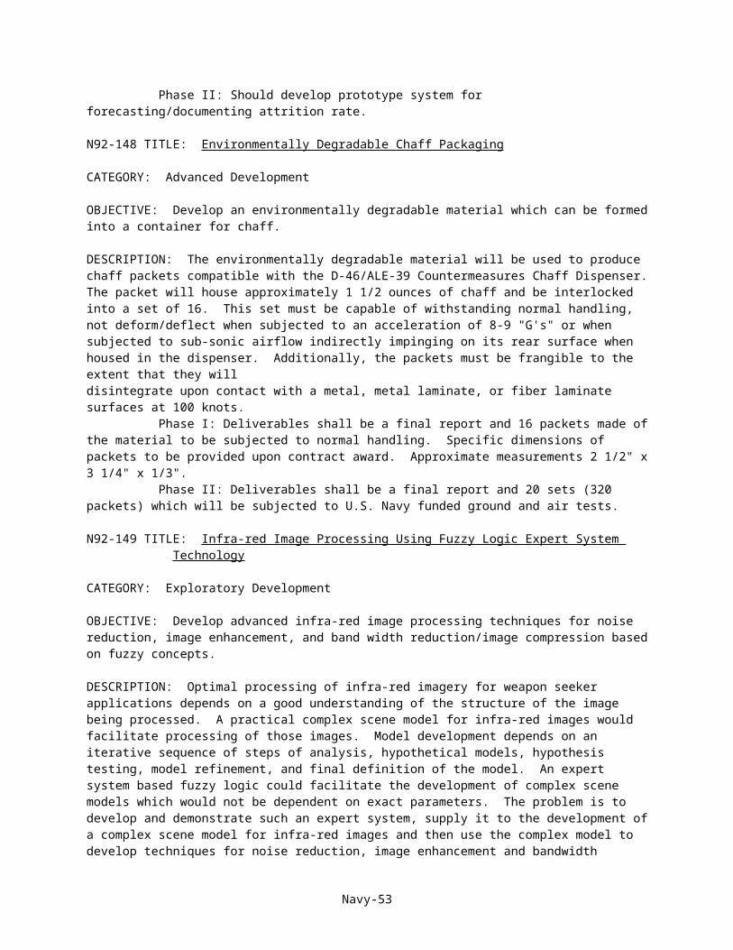
CATEGORY: Engineering Development
OBJECTIVE: Provide for the definition and development of a standard 1553 Bus Controller for use with current and future air propulsion systems. An economical and efficient means of interfacing to the FADECs used with the various engines in the Navy inventory is sought.
DESCRIPTION: Engines developed for the Navy are equipped with FADECs containing a 1553 Bus interface. All future engines are expected to be so equipped. At present, either the engine manufacture provides the engine test facility with a controller unit, or the test facility must purchase or rent a controller identical to the one used by the manufacturer. As more engines are developed and manufactured with FADECs outfitted with 1553 Bus interfaces, this method of providing for bus controllers becomes more cumbersome, inadequate, and costly, since the Navy is faced with the need to support a multitude of controllers. The bus controller should be tailored for control room use at engine test facilities. Interface to the engine operator panel should remain consistent from test to test. Real time display of parameters should be developed. A reliable interface to the facility main frame computer should be established which will allow quick turn around time of data. Engines utilizing FADECs which require 1553 bus Controllers will ultimately be rebuilt and tested at NARFS. These facilities will be faced with the need to obtain bus controllers. The standard 1553 Bus controllers developed for NAPC would find direct application at these facilities. Phase I: The first phase of the research is to conclude a feasibility study. The study will: 1) analyze hardware and software requirements; and 2) complete a detailed proposal for a prototype standard 1553 Bus controller. The concept must allow for configuration by the user, interface to control room displays and inputs, and communication of information to a main frame computer in real time. Event recording with play back capability is also required. Phase II: The prototype defined in phase I is to be constructed and tested to preset guidelines. The test will determine the effectiveness of the proposed methodology under NAPC specified conditions. The prototype demonstration will include validation of the concept under actual test conditions.
NAVAL AIR TEST CENTER
N92-180 TITLE: Anechoic Chamber Radiated Environment
CATEGORY: Exploratory Development OBJECTIVE: To design and install a low-cost, wide-band radio frequency (rf) radiated environment to be permanently installed in the rf shielded walls of anechoic chambers. This capability will permit "quick look" tests where fine direction of arrival is not required.
DESCRIPTION: When an installed electronic system which needs rf stimulation is placed in an anechoic chamber, three primary means of providing a signal environment are utilized: accurate, but time-consuming behind-the-antenna, utilizing directional couplers, radiated environment from antennas temporarily mounted on tripods, or extremely expensive in-wall antenna arrays and/or turntables. The anechoic chamber radiated environment capability proposed would provide an extremely rapid, yet low-cost means of testing installed systems. Phase I: Design of specialized antennas and/or the methodology for installing off-the-shelf antennas in the shielded chamber walls without compromising shielding effectiveness or anechoic performance. A concurrent effort would be the design of moveable proof-of-concept "billboard" arrays containing high power broadband amplifiers and high-speed rf switching networks, under computer control, to provide a limited but polarization and spatially diverse, radiated RF environment. These billboards would be capable of interfacing with the Tactical Electronic Warfare Environment Simulator (TEWES) or other source of simulated radar and/or communications type signals to provide a realistic radiated threat environment from a limited azimuth and elevation sector. Phase II: Would develop and demonstrate two moveable proof-of-concept billboard arrays containing high power broadband amplifiers and high-speed switching networks to provide a wide-band, polarization diverse, limited resolution radiated environment. This phase will also include the development of a interface between the
Navy-53

Advanced TEWES and the billboard arrays and provide the Initial Operating Capability (IOC) of a low-cost Anechoic Chamber Radiated Environment.
N92-181 TITLE: Wireless Airborne Instrumentation System
CATEGORY: Exploratory Research
OBJECTIVE: Develop small, self-contained transmitter modules and a receiver module which will allow the transmission of transducer data from a remote part of a test aircraft or missile to a central acquisition system without the need for connecting hard wiring. Modules operating on internal power, able to handle multiple local transducers, and able to withstand the environment of a modern jet fighter aircraft are required.
DESCRIPTION: About half of the cost of modern flight test instrumentation system installations results from the need to run instrumentation wiring throughout the aircraft to connect the various transducers to a central data acquisition system and to provide the transducers with the necessary electrical power. Elimination of this requirement would result in significant savings in flight test program cost, and in the time required to complete the installation. Phase I: Provide a specification of the basic system requirements, identify any needed testing required to establish the ability of likely equipment to withstand the complete operating environment of such a system and to provide the required performance, and identify potential equipment, either currently available or to be developed, that could be used to meet these requirements. Phase II: Develop a prototype transmitter and receiver unit and provide laboratory testing to demonstrate that this system can provide the required operating performance. If development progress will allow a flight evaluation of the equipment, make the prototype available for Navy flight evaluation. Such a prototype system would not have to provide the full multiple-channel capability nor operating endurance suitable for a production system, but should demonstrate the feasibility of the approach.
N93-182 TITLE: Infrared Optical Fibers
CATEGORY: Engineering Development
OBJECTIVE: To develop optical fibers capable of relaying high quality infrared (IR) images over distances of 100 to 150 feet in the 3-5 and 8-12 micron regions. If successful, the optical fibers developed will be integrated into the Offensive Sensors Laboratory IR Scene Generation System that is currently under design.
DESCRIPTION: Current optical fibers relay information using visible light or lasers. The purpose of this project is to determine if optical fibers capable of relaying high quality IR images can be developed and produced at a reasonable cost. The optical fibers should be able to handle IR transmissions in the 3-12 micron range over distances of 100 to 150 feet with minimal loss. If the full range of wavelengths is not possible, the fibers must be able to handle IR transmissions in the 3-5 and 8-12 micron regions. The fibers must be able to handle coherent imaging and diffraction limited images. The fibers must be capable of working with a focal attachments at either end of the fibers, preferably attached to the fibers or with the maximum numerical aperture bundles at one end of the fibers. If possible, the fibers should emulate atmospheric transmission in the 3-12 micron region. Phase I: Should consist of a study outlining the approach which will be undertaken to pursue the requirements addressed above with sufficient data to demonstrate feasibility. Phase II: Should use the approach outlined in Phase I to produce two optical fibers 100 feet in length and two optical fibers 150 feet in length and deliver them to the government for testing.
N92-183 TITLE: Artificial Intelligence (AI) Technology to Enhance Flight Test Software Configuration Control
CATEGORY: Exploratory Development
OBJECTIVE: Use AI technology to develop a program that can determine the parametric effects of software changes to specified configurations during flight testing.
Navy-54
DESCRIPTION: Testing a modern rotorcraft operational flight trainer (OFT), weapon systems trainer (WST), or rotorcraft digital flight control system involves numerous software changes by the contractor. The government test team tries to maintain configuration control, testing a "frozen" configuration. The contractor may say that he/she can make a half dozen software corrections in 5 min without affecting any of the previous testing. Considerable cross-coupling exists in helicopter flight characteristics, and trade-offs exist between testing a frozen configuration and in making software changes to enhance the configuration. The purpose of this project is to develop a program that can analyze flight trainer or digital flight control system block diagrams, prints, etc., and perturb the system, and determine the parametric effects of software configuration changes. Phase I: Review software configuration control during typical Navy flight trainer acceptance testing, and software configuration control during rotorcraft digital flight control system testing. Develop a plan for a program, using AI technology, to help the test team enhance configuration control. Phase II: Use the approach documented in Phase I to develop the AI technology configuration control enhancement software. Demonstrate and support testing the AI software in conjunction with a specified Navy flight trainer test program and digital flight control test program. Correct problems and incorporate recommended changes resulting from the initial tests. Deliver final product, with appropriate documentation, to the Navy.
NAVAL WEAPONS CENTER
N92-184 TITLE: Radiation Heat Transfer Analysis
CATEGORY: Advanced Development
OBJECTIVE: To develop a computer software package that provides solutions to radiant energy exchange in enclosures over multiple wavelength bands and with participating media. In addition, the software would integrate this radiant energy exchange analysis capability with the pre- and postprocessing capabilities of the MOVIESTAR computer program to build a heat transfer model and interface with general thermal analyzers such as SINDA, TMG, and ABAQUS which predict thermal response of the system.
DESCRIPTION: The purpose of this project is to provide Navy engineers with an economical alternative to leasing proprietary radiation heat transfer analysis software such as those obtainable in commercial software packages. Existing radiant energy exchange analysis software that determines radiation viewfactors in multiple enclosures could be modified to interface with the MOVIESTAR and ABAQUS as part of a Phase I effort to demonstrate feasibility. Phase II: Should use the approach demonstrated in Phase I to interface with additional general thermal analyzers (e.g. SINDA, TMG, etc) and to develop radiation analysis software that provides multiple wavelength band radiation modeling and that includes participating media.
N92-185 TITLE: Improved Thermal Neutron Imaging Method
CATEGORY: Exploratory Development
OBJECTIVE: Develop an improved method of imaging thermal neutrons in real-time or near real-time, suitable for use in (or as) an electronic neutron radiography imaging system.
DESCRIPTION: A new family of accelerators provides the opportunity for neutron radiography to move from the reactor based systems to a more attractive accelerator system that can offer portability and turn-key operation without the hazards of the reactor. An improved method of imaging thermal neutrons that will be provided by the new accelerator family that has a 106 n/cm2/sec thermal flux, length/diameter ratio of 25, with a desired 12 inch x 12 inch image size. These parameters are approximate and there are some additional unknowns that will be established when the solicitation is released. The component or system will be used to image dynamic events in addition to the traditional static test item neutron radiography. The primary parameters for improvement should be signal to noise ratio, spatial resolution, and contrast sensitivity.
Navy-55

Phase I: Evaluate present thermal neutron imaging systems and neutron detectors and compare them to the proposed method. Demonstrate a sub-scale system or component for a proof of concept with a final report. Phase II: Fabricate a prototype system or component that will fit into a commercially available system with the intention of marketing the developed item.
N92-186 TITLE: Laser Beam Steering Via the Pockels Effect
CATEGORY: Exploratory Development
OBJECTIVE: Build a low cost, laser beam steering device which can change beam direction at GHz frequencies. Applications include components for hybrid optical computers and laser radar.
DESCRIPTION: Nonlinear optical polymers (NLOP) offer an excellent opportunity for fabricating low cost electro-optical waveguides for GHz phase modulation. An electro-optical waveguide consists of a layer of nonlinear optical polymer (NLOP) sandwiched between transparent buffer polymer and electrodes. When an electrical field is applied across a portion of the NLOP, the index of refraction of the NLOP is changed. This change is due to p-electron shifts which occur in less than a picosecond. State-of-the-art NLOP require several centimeters of interaction length to achieve 2p phase change at acceptable modulation voltages.5 Hence, to steer a laser beam over wide angles, a novel device configuration is required, for example, one involving an array of NLOP waveguides, fabricated by microlithography. Successful proposals will include a detailed drawing of a novel beam steering device. Serious consideration will only be given to investigators experienced in fabricating optical waveguides. Phase I: The expected deliverable will be a report outlining the approach and providing performance data on prototype materials, e.g., optical rotation in NLOP as a function of the applied electric field. The NLOP should exhibit an effective c(2) coefficient greater than 30 pm/V and attenuate less than 3 dB/cm at the wavelength of interest (e.g., 532 nm or greater). Any source of NLOP is acceptable. The NLOP may also be provided by the Naval Preparing Activity (Naval Weapons Center, China Lake, CA,). Phase II: Expected deliverable will be a breadboard laser beam deflector. Investigators at the Naval Weapons Center at China Lake, CA, will be responsible for verifying the optical testing and performance results.
PACIFIC MISSILE TEST CENTER
N92-187 TITLE: Dual Mode Infrared (IR)/Millimeter Wave (MMW) Measurement System
CATEGORY: Engineering Development
OBJECTIVE: To design, fabricate, test and deliver a dual mode IR/MMW sensor measurement system for air-to-air and air-to-ground measurements of military targets. The system shall be capable of airborne operation in the Pacific Missile Test Center Airborne Turret IR Measurement System (ATIMS) or ground operation from remote sites.
DESCRIPTION: Dual mode IR/MMW weapons systems are now under development within the DoD. A need exists to make target signature measurements in these two bands simultaneously.An airborne measurement system which operates simultaneously in the 3-5 and 8-12 micrometer bands of the IR and 35 and 94 gigahertz bands of the MMW is required. The IR portion of the system shall be a high resolution, passive imager. The MMW portion of the system shall be active and provide range versus line of sight data. The IR and MMW data shall be in a format of recording on an airborne wide band data tape recorder or video tape recorder. The IR and MMW data must be tagged so that they can be registered during data reduction. Phase I: A concept for the system will be developed and the engineering design will be completed. The deliverable will be a final report. Phase II: The systems will be fabricated, tested and delivered to the Pacific Missile Test Center. The deliverables will be the system hardware, a drawing package and an operating/maintenance manual.
Navy-56
N92-188 TITLE: Multi-Spectral Scene Generation for Hardware-in-the-loop (HWIL) Laboratories
CATEGORY: Exploratory Development
OBJECTIVE: To design and develop a target screen for multi-spectral HWIL laboratories which is reflective in the infrared (IR) region and transmissive in the microwave region.
DESCRIPTION: Dual mode missile systems are under development in all three services. Complete test and evaluation of these very complex systems requires the use of realistic dual mode HWIL laboratories. Such laboratories are envisioned as being radio frequency (RF) chambers with an array of RF sources on one wall and the missile under test located at the opposite end of the laboratory. The missile guidance systems will be mounted in a multi-axis angular motion simulator. The target screen will be placed between the RF source array and the missile under test. IR sources, mounted near the missile under test, will project an IR scene onto the screen which will reflect it to the missile. The IR and RF images will be registered providing a dual mode RF/IR target scene. Phase I: A concept for an IR reflecting/RF transmitting screen will be developed and fully analyzed. The deliverable will be a final report describing the screen concept and estimating its capabilities. Phase II: The screen will be fabricated, tested and delivered to the Pacific Missile Test Center. The deliverables will be the screen hardware and a report describing its technical parameters and test results.
Navy-57