Navigator Installation - Timewave Technology Inc. Installation ... I followed the procedure for...
16
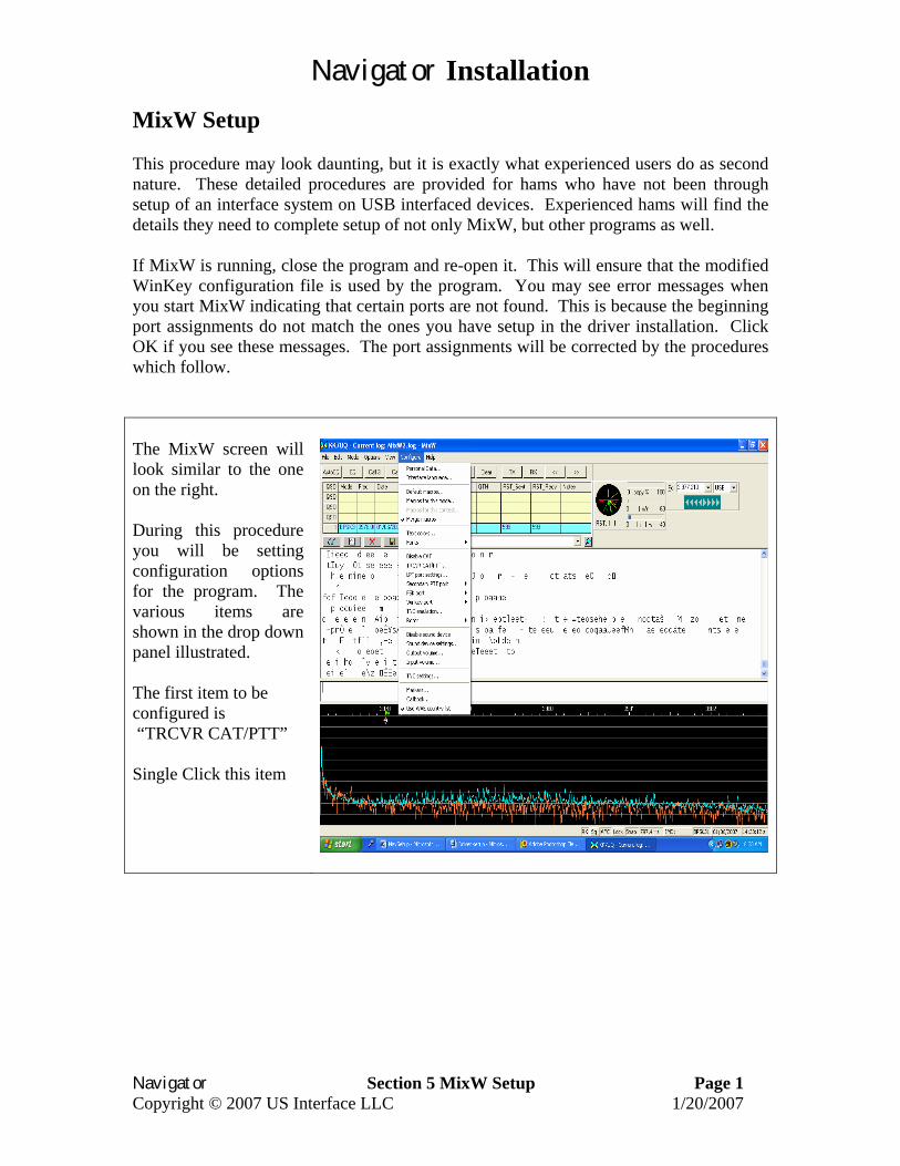
Navigator Installation Navigator Section 5 MixW Setup Page 1 Copyright © 2007 US Interface LLC 1/20/2007 MixW Setup This procedure may look daunting, but it is exactly what experienced users do as second nature. These detailed procedures are provided for hams who have not been through setup of an interface system on USB interfaced devices. Experienced hams will find the details they need to complete setup of not only MixW, but other programs as well. If MixW is running, close the program and re-open it. This will ensure that the modified WinKey configuration file is used by the program. You may see error messages when you start MixW indicating that certain ports are not found. This is because the beginning port assignments do not match the ones you have setup in the driver installation. Click OK if you see these messages. The port assignments will be corrected by the procedures which follow. The MixW screen will look similar to the one on the right. During this procedure you will be setting configuration options for the program. The various items are shown in the drop down panel illustrated. The first item to be configured is “TRCVR CAT/PTT” Single Click this item
-
Upload
phunghuong -
Category
Documents
-
view
221 -
download
5
Transcript of Navigator Installation - Timewave Technology Inc. Installation ... I followed the procedure for...
Navigator Installation
Navigator Section 5 MixW Setup Page 1 Copyright © 2007 US Interface LLC 1/20/2007
MixW Setup This procedure may look daunting, but it is exactly what experienced users do as second nature. These detailed procedures are provided for hams who have not been through setup of an interface system on USB interfaced devices. Experienced hams will find the details they need to complete setup of not only MixW, but other programs as well. If MixW is running, close the program and re-open it. This will ensure that the modified WinKey configuration file is used by the program. You may see error messages when you start MixW indicating that certain ports are not found. This is because the beginning port assignments do not match the ones you have setup in the driver installation. Click OK if you see these messages. The port assignments will be corrected by the procedures which follow. The MixW screen will look similar to the one on the right. During this procedure you will be setting configuration options for the program. The various items are shown in the drop down panel illustrated. The first item to be configured is “TRCVR CAT/PTT” Single Click this item
Navigator Installation
Navigator Section 5 MixW Setup Page 2 Copyright © 2007 US Interface LLC 1/20/2007
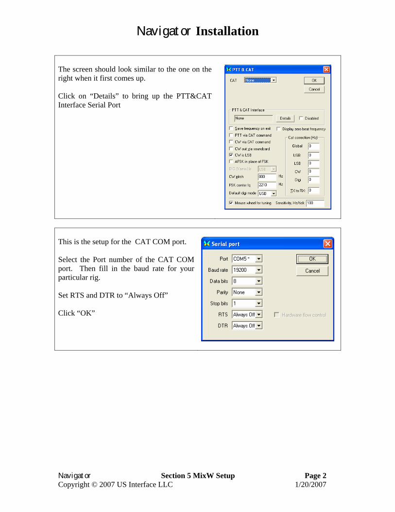
The screen should look similar to the one on the right when it first comes up. Click on “Details” to bring up the PTT&CAT Interface Serial Port
This is the setup for the CAT COM port. Select the Port number of the CAT COM port. Then fill in the baud rate for your particular rig. Set RTS and DTR to “Always Off” Click “OK”
Navigator Installation
Navigator Section 5 MixW Setup Page 3 Copyright © 2007 US Interface LLC 1/20/2007
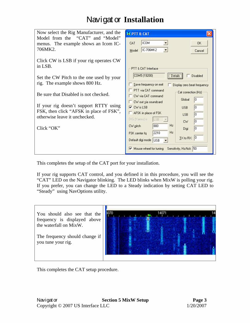
Now select the Rig Manufacturer, and the Model from the “CAT” and “Model” menus. The example shows an Icom IC-706MK2. Click CW is LSB if your rig operates CW in LSB. Set the CW Pitch to the one used by your rig. The example shows 800 Hz. Be sure that Disabled is not checked. If your rig doesn’t support RTTY using FSK, then click “AFSK in place of FSK”, otherwise leave it unchecked. Click “OK”
This completes the setup of the CAT port for your installation. If your rig supports CAT control, and you defined it in this procedure, you will see the “CAT” LED on the Navigator blinking. The LED blinks when MixW is polling your rig. If you prefer, you can change the LED to a Steady indication by setting CAT LED to “Steady” using NavOptions utility. You should also see that the frequency is displayed above the waterfall on MixW. The frequency should change if you tune your rig.
This completes the CAT setup procedure.
Navigator Installation
Navigator Section 5 MixW Setup Page 4 Copyright © 2007 US Interface LLC 1/20/2007
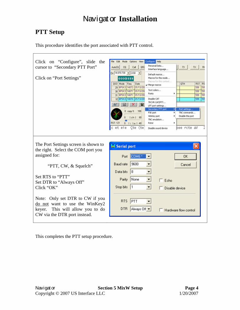
PTT Setup This procedure identifies the port associated with PTT control. Click on “Configure”, slide the cursor to “Secondary PTT Port” Click on “Port Settings”
The Port Settings screen is shown to the right. Select the COM port you assigned for:
“PTT, CW, & Squelch” Set RTS to “PTT” Set DTR to “Always Off” Click “OK” Note: Only set DTR to CW if you do not want to use the WinKey2 keyer. This will allow you to do CW via the DTR port instead.
This completes the PTT setup procedure.
Navigator Installation
Navigator Section 5 MixW Setup Page 5 Copyright © 2007 US Interface LLC 1/20/2007
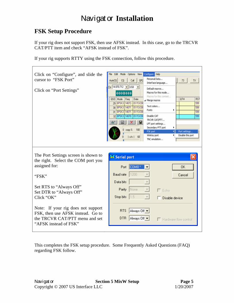
FSK Setup Procedure If your rig does not support FSK, then use AFSK instead. In this case, go to the TRCVR CAT/PTT item and check “AFSK instead of FSK”. If your rig supports RTTY using the FSK connection, follow this procedure.
Click on “Configure”, and slide the cursor to “FSK Port” Click on “Port Settings”
The Port Settings screen is shown to the right. Select the COM port you assigned for: “FSK” Set RTS to “Always Off” Set DTR to “Always Off” Click “OK” Note: If your rig does not support FSK, then use AFSK instead. Go to the TRCVR CAT/PTT menu and set “AFSK instead of FSK”
This completes the FSK setup procedure. Some Frequently Asked Questions (FAQ) regarding FSK follow.

Navigator Installation
Navigator Section 5 MixW Setup Page 6 Copyright © 2007 US Interface LLC 1/20/2007
FAQ about FSK operation with Navigator
1. Q. I followed the procedure for setup with MixW and FSK worked fine. Then I switched to MMTTY and now when I send a long FSK message, the screen says I am through, but some characters are still being sent at the end. A. The problem is that the default MMTTY setup puts the stop bits at 1.5. MixW like 2. If you did not change the stop bit setting in NavOptions, then MMTTY sent it’s data faster to Navigator than the output rate. There is a FIFO buffer in the FSK Controller, so that all of the data was received by Navigator, but it was still sending when MMTTY thought it was through. Fortunately, the FSK controller provides it’s own PTT, which is synchronized with the output data, so all of the data got sent. You could also have changed the stop bit rate in MMTTY to 2 bits if you prefer. Also, see section 7 of the Navigator Installation documents for more information about setup with MMTTY.
2. Q. I have a Kenwood transceiver, so I set the FSK polarity in NavOptions to
Reverse. I set the invert bit in MixW as well. The output data seems fine, but reading RTTY signals is garbage. A. The polarity of the FSK signal does require reverse with a Kenwood, but that has nothing to do with reading RTTY signals. RTTY is usually set to a Lower Side Band mode (LSB) so the “Normal” settings are set for that. If your transceiver operates in Upper Side Band (USB) then you should use the invert control in MixW. In your case, uncheck the invert control in MixW and you will be fine.
3. Q. When operating in FSK the RF OUT control on Navigator has no effect
on rig output power. A. FSK RTTY is not a sound device mode (unless you are using AFSK). The power level is determined only by the rig RF output power control.
4. Q. I set my sound device settings to Full Duplex, so I could see what the
audio input looks like while transmitting. In both CW and RTTY modes, I see very large signals, with appreciable harmonics. Is this going out over the air? A. No, these strong signals are not going out over the air. What you are seeing is the square wave side tone signal from the Navigator Monitor being fed back to the audio input channel. In the case of both CW and RTTY, only the digital control signals for CW and FSK are being sent to the rig.
Navigator Installation
Navigator Section 5 MixW Setup Page 7 Copyright © 2007 US Interface LLC 1/20/2007
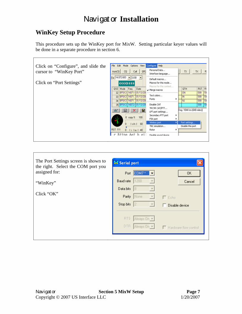
WinKey Setup Procedure This procedure sets up the WinKey port for MixW. Setting particular keyer values will be done in a separate procedure in section 6.
Click on “Configure”, and slide the cursor to “WinKey Port” Click on “Port Settings”
The Port Settings screen is shown to the right. Select the COM port you assigned for: “WinKey” Click “OK”
Navigator Installation
Navigator Section 5 MixW Setup Page 8 Copyright © 2007 US Interface LLC 1/20/2007
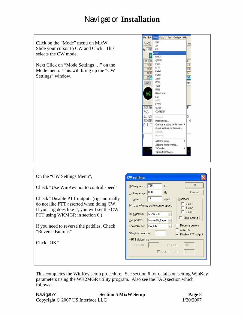
Click on the “Mode” menu on MixW. Slide your cursor to CW and Click. This selects the CW mode. Next Click on “Mode Settings …” on the Mode menu. This will bring up the “CW Settings” window.
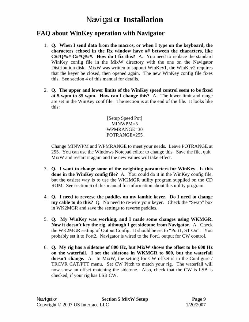
On the “CW Settings Menu”, Check “Use WinKey pot to control speed” Check “Disable PTT output” (rigs normally do not like PTT asserted when doing CW. If your rig does like it, you will set the CW PTT using WKMGR in section 6.) If you need to reverse the paddles, Check “Reverse Buttons” Click “OK”
This completes the WinKey setup procedure. See section 6 for details on setting WinKey parameters using the WK2MGR utility program. Also see the FAQ section which follows.
Navigator Installation
Navigator Section 5 MixW Setup Page 9 Copyright © 2007 US Interface LLC 1/20/2007
FAQ about WinKey operation with Navigator
1. Q. When I send data from the macros, or when I type on the keyboard, the characters echoed in the Rx window have ## between the characters, like C##Q### C##Q###. How do I fix this? A. You need to replace the standard WinKey config file in the MixW directory with the one on the Navigator Distribution disk. MixW was written to support WinKey1, the WinKey2 requires that the keyer be closed, then opened again. The new WinKey config file fixes this. See section 4 of this manual for details.
2. Q. The upper and lower limits of the WinKey speed control seem to be fixed
at 5 wpm to 35 wpm. How can I change this? A. The lower limit and range are set in the WinKey conf file. The section is at the end of the file. It looks like this:
[Setup Speed Pot]
MINWPM=5 WPMRANGE=30 POTRANGE=255
Change MINWPM and WPMRANGE to meet your needs. Leave POTRANGE at 255. You can use the Windows Notepad editor to change this. Save the file, quit MixW and restart it again and the new values will take effect.
3. Q. I want to change some of the weighting parameters for WinKey. Is this
done in the WinKey config file? A. You could do it in the WinKey config file, but the easiest way is to use the WK2MGR utility program supplied on the CD ROM. See section 6 of this manual for information about this utility program.
4. Q. I need to reverse the paddles on my iambic keyer. Do I need to change
my cable to do this? Q. No need to re-wire your keyer. Check the “Swap” box in WK2MGR and save the settings to reverse paddles.
5. Q. My WinKey was working, and I made some changes using WKMGR.
Now it doesn’t key the rig, although I get sidetone from Navigator. A. Check the WK2MGR setting of Output Config. It should be set to “Port1, ST On”. You probably set it to Port2. Navigator is wired to the Port1 output for CW control.
6. Q. My rig has a sidetone of 800 Hz, but MixW shows the offset to be 600 Hz
on the waterfall. I set the sidetone in WKMGR to 800, but the waterfall doesn’t change. A. In MixW, the setting for CW offset is in the Configure / TRCVR CAT/PTT menu. Set CW Pitch to match your rig. The waterfall will now show an offset matching the sidetone. Also, check that the CW is LSB is checked, if your rig has LSB CW.
Navigator Installation
Navigator Section 5 MixW Setup Page 10 Copyright © 2007 US Interface LLC 1/20/2007
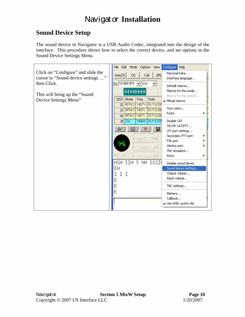
Sound Device Setup The sound device in Navigator is a USB Audio Codec, integrated into the design of the interface. This procedure shows how to select the correct device, and set options in the Sound Device Settings Menu. Click on “Configure” and slide the cursor to “Sound device settings …” then Click. This will bring up the “Sound Device Settings Menu”
Navigator Installation
Navigator Section 5 MixW Setup Page 11 Copyright © 2007 US Interface LLC 1/20/2007
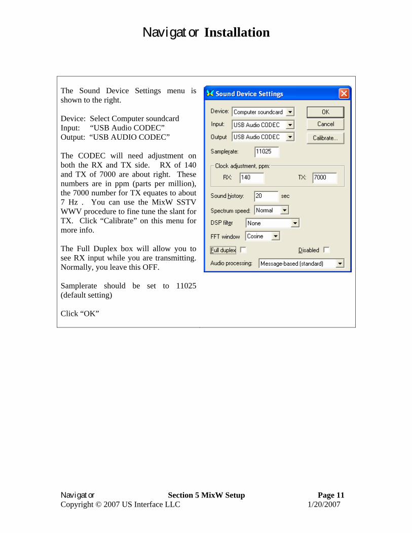
The Sound Device Settings menu is shown to the right. Device: Select Computer soundcard Input: “USB Audio CODEC” Output: “USB AUDIO CODEC” The CODEC will need adjustment on both the RX and TX side. RX of 140 and TX of 7000 are about right. These numbers are in ppm (parts per million), the 7000 number for TX equates to about 7 Hz . You can use the MixW SSTV WWV procedure to fine tune the slant for TX. Click “Calibrate” on this menu for more info. The Full Duplex box will allow you to see RX input while you are transmitting. Normally, you leave this OFF. Samplerate should be set to 11025 (default setting) Click “OK”
Navigator Installation
Navigator Section 5 MixW Setup Page 12 Copyright © 2007 US Interface LLC 1/20/2007
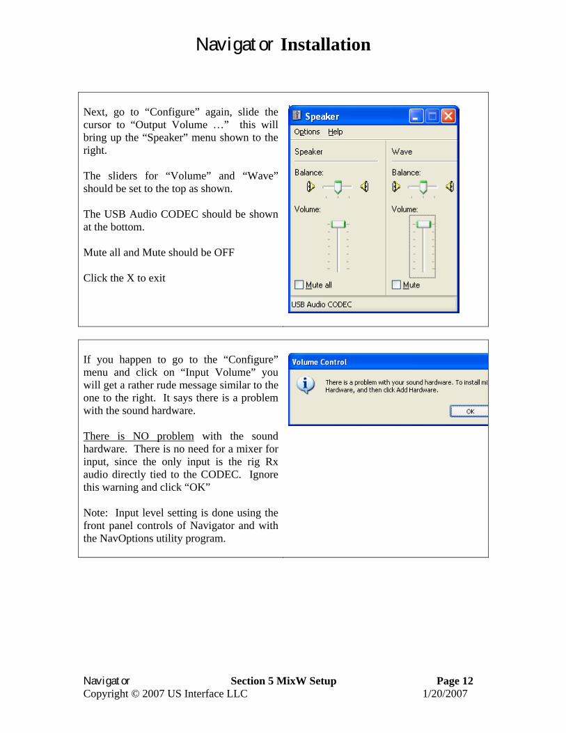
Next, go to “Configure” again, slide the cursor to “Output Volume …” this will bring up the “Speaker” menu shown to the right. The sliders for “Volume” and “Wave” should be set to the top as shown. The USB Audio CODEC should be shown at the bottom. Mute all and Mute should be OFF Click the X to exit
If you happen to go to the “Configure” menu and click on “Input Volume” you will get a rather rude message similar to the one to the right. It says there is a problem with the sound hardware. There is NO problem with the sound hardware. There is no need for a mixer for input, since the only input is the rig Rx audio directly tied to the CODEC. Ignore this warning and click “OK” Note: Input level setting is done using the front panel controls of Navigator and with the NavOptions utility program.
Navigator Installation
Navigator Section 5 MixW Setup Page 13 Copyright © 2007 US Interface LLC 1/20/2007
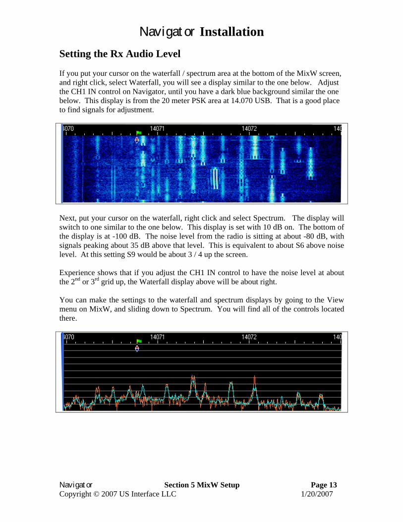
Setting the Rx Audio Level If you put your cursor on the waterfall / spectrum area at the bottom of the MixW screen, and right click, select Waterfall, you will see a display similar to the one below. Adjust the CH1 IN control on Navigator, until you have a dark blue background similar the one below. This display is from the 20 meter PSK area at 14.070 USB. That is a good place to find signals for adjustment.
Next, put your cursor on the waterfall, right click and select Spectrum. The display will switch to one similar to the one below. This display is set with 10 dB on. The bottom of the display is at -100 dB. The noise level from the radio is sitting at about -80 dB, with signals peaking about 35 dB above that level. This is equivalent to about S6 above noise level. At this setting S9 would be about 3 / 4 up the screen. Experience shows that if you adjust the CH1 IN control to have the noise level at about the 2nd or 3rd grid up, the Waterfall display above will be about right. You can make the settings to the waterfall and spectrum displays by going to the View menu on MixW, and sliding down to Spectrum. You will find all of the controls located there.
Navigator Installation
Navigator Section 5 MixW Setup Page 14 Copyright © 2007 US Interface LLC 1/20/2007
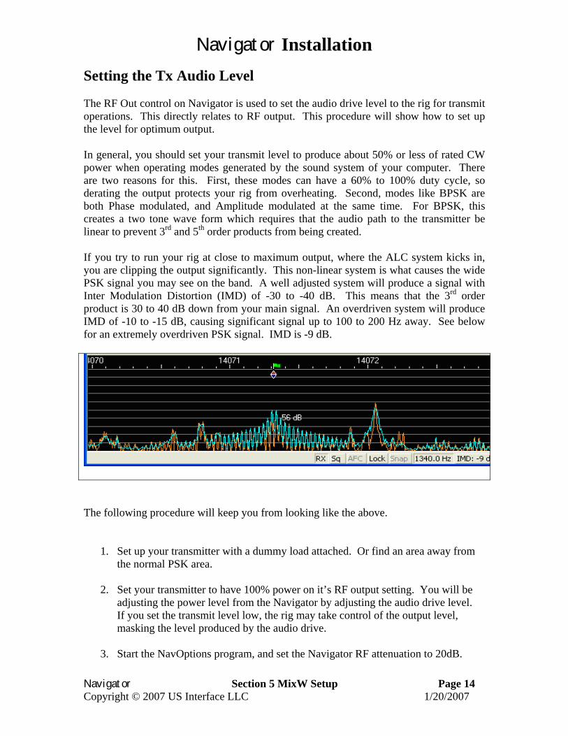
Setting the Tx Audio Level The RF Out control on Navigator is used to set the audio drive level to the rig for transmit operations. This directly relates to RF output. This procedure will show how to set up the level for optimum output. In general, you should set your transmit level to produce about 50% or less of rated CW power when operating modes generated by the sound system of your computer. There are two reasons for this. First, these modes can have a 60% to 100% duty cycle, so derating the output protects your rig from overheating. Second, modes like BPSK are both Phase modulated, and Amplitude modulated at the same time. For BPSK, this creates a two tone wave form which requires that the audio path to the transmitter be linear to prevent 3rd and 5th order products from being created. If you try to run your rig at close to maximum output, where the ALC system kicks in, you are clipping the output significantly. This non-linear system is what causes the wide PSK signal you may see on the band. A well adjusted system will produce a signal with Inter Modulation Distortion (IMD) of -30 to -40 dB. This means that the 3rd order product is 30 to 40 dB down from your main signal. An overdriven system will produce IMD of -10 to -15 dB, causing significant signal up to 100 to 200 Hz away. See below for an extremely overdriven PSK signal. IMD is -9 dB.
The following procedure will keep you from looking like the above.
1. Set up your transmitter with a dummy load attached. Or find an area away from the normal PSK area.
2. Set your transmitter to have 100% power on it’s RF output setting. You will be
adjusting the power level from the Navigator by adjusting the audio drive level. If you set the transmit level low, the rig may take control of the output level, masking the level produced by the audio drive.
3. Start the NavOptions program, and set the Navigator RF attenuation to 20dB.

Navigator Installation
Navigator Section 5 MixW Setup Page 15 Copyright © 2007 US Interface LLC 1/20/2007
4. Turn the Navigator RF OUT control full counter clockwise (CCW).
5. Put the cursor on the MixW waterfall to about 1500 Hz up from the edge. If your
rig is set to 14.070, then set the cursor to 14.071.5
6. Go to the MixW Options menu and select “Tune transmitter”. This will put out a continuous, unmodulated tone at 1500 Hz. Note: to stop this signal, you must hit the ESC key.
7. You should not be putting out any power, but will hear the tone in the Monitor on
Navigator. With NavOptions RF Atten at 20dB, turn the RF OUT knob clockwise until you see power output on your rig. If you turn it full clockwise, and do not see power, or very little, turn the knob back to CCW, go to NavOptions and set RF Atten to Normal. Turn the knob clockwise again and you should see power on your meter. Set the power level to about 50% of full rated power. For a 100 watt transmitter, set it at 50 W or below. Hit the ESC key to stop transmitting.
8. Now set MixW to BPSK31 if it is not already there. Click on the TX button at the
top of the screen, and you should now be putting out an Idle PSK signal. Note the change in tone of the signal on the Navigator monitor. Your power output will show about 25 to 30 watts average power out. If your meter has a peak reading control, set it to peak, and watch the power level go back to 50 watts. The Idle signal has a duty cycle of about 60%. If you type, the average power level will increase. Hit the RX button, or the ESC key to stop transmitting.
9. Your power level is now set for clean operation.
10. This completes the TX Level adjustment procedure. Some frequently asked
questions (FAQ) follow regarding power levels. FAQ about power levels
1. Q. I had my system all set up for TX Level, then ran some other programs. When I brought the system up again, the power levels were way down. What happened? A. Most likely, the PC audio level sliders on the output volume control panel were changed by another application. Use a free program like QuickMix (http://www.ptpart.co.uk/quickmix/) to automatically set your power levels when you start your application program
2. Q. I notice that when I move my cursor to 3000 Hz offset, the power level really
drops off. A. Your rig is and SSB rig, with an audio bandpass corner frequency of around 2300 Hz. When you move the cursor on the waterfall above the corner frequency of the rig output filter, most of the audio drive has been cutoff. Same thing happens on the lower end of the filter. A good rule of thumb is to keep the
Navigator Installation
Navigator Section 5 MixW Setup Page 16 Copyright © 2007 US Interface LLC 1/20/2007
cursor from about 500 Hz to 2200 Hz offset. If the signal you want to contact is outside of that, move the base frequency on your rig.
3. Q. Even if I stay within the transmit passband, I see a difference in output
power with different settings. A. The transmit audio bandpass filter on many rigs is any thing but flat topped. Some rigs have a measured variation of 3dB across the passband. The advantage of having a physical control on the Navigator is that the power level is easily adjusted as opposed to using software level controls.
4. Q. When I change bands, the power output changes for the same cursor offset. A. This is typical of SSB transmitters. Normally, the ALC takes care of these differences, since for voice the levels are boosted to attain a full sound anyway. With digital modes, you are operating in the linear range, below the ALC level. Use the RF OUT control on Navigator to bring the level to where you want it.
5. Q. What about other modes than PSK? A. Sound device generated modes
such as MFSK16, Olivia, MT63 and AFSK are frequency shifting modes, running at about 100% duty cycle. The settings you use for PSK should be maintained for these modes as well, mainly to protect your rig from overheat as well as distortion.
6. Q. What about FSK RTTY and CW? How do I adjust the power level with
those modes? A. These modes do not use the Audio Codec to generate the signal. The power levels are determined within your rig. Use the rig power level to control output power.
7. Q. I want to run my rig at higher than 50% level – how do I ensure that my
signal is clean? A. If you do this, you should use an external monitoring device such as the PSK meter (www.ssiserver.com/info/pskmeter/) or an IMD meter (www.USInterface.com ). Set your rig output level to whatever level you want as max, then monitor your quality using one of these meters. Again, be careful of the heat level of your rig if you follow this method.
Setup Procedures with Other Software These procedures have focused on the MixW software, and serve as an example of how to set port numbers and audio level. Other sections of the Navigator Installation document deal with CW setup using the WKMGR utility (section 6), and “MMTTY setup for FSK” (section 7).