NAVFAC DM5-4 Civil Engineering Pavements · the design of subgrade, subbase, and base courses,...
61
PDHonline Course C135 (6 PDH) Pavement Design 2012 Instructor: John C. Huang, Ph.D., PE PDH Online | PDH Center 5272 Meadow Estates Drive Fairfax, VA 22030-6658 Phone & Fax: 703-988-0088 www.PDHonline.org www.PDHcenter.com An Approved Continuing Education Provider
-
Upload
nguyenkhuong -
Category
Documents
-
view
219 -
download
0
Transcript of NAVFAC DM5-4 Civil Engineering Pavements · the design of subgrade, subbase, and base courses,...
PDHonline Course C135 (6 PDH)
Pavement Design
2012
Instructor: John C. Huang, Ph.D., PE
PDH Online | PDH Center5272 Meadow Estates Drive
Fairfax, VA 22030-6658Phone & Fax: 703-988-0088
www.PDHonline.orgwww.PDHcenter.com
An Approved Continuing Education Provider
+)))))))))))))))))))))))))))))))))))))))))))))))))))))))))))))))))))))), * CCB Application Notes: ** ** 1. Character(s) preceded & followed by these symbols (. -) or (+ ,) ** are super- or subscripted, respectively. ** EXAMPLES: 42m.3- = 42 cubic meters ** CO+2, = carbon dioxide ** ** 2. All degree symbols have been replaced with the word deg. ** ** 3. All plus or minus symbols have been replaced with the symbol +/-. ** ** 4. All table note letters and numbers have been enclosed in square ** brackets in both the table and below the table. ** ** 5. Whenever possible, mathematical symbols have been replaced with ** their proper name and enclosed in square brackets. *.))))))))))))))))))))))))))))))))))))))))))))))))))))))))))))))))))))))-

DEPARTMENT OF THE NAVYNAVAL FACILITIES ENGINEERING COMMAND200 Stovall StreetAlexandria, VA 22332-2300 APPROVED FOR RELEASE)))))))))))))))))))))))))))))))))))))))))))))))))))))))))))))))))))))))))))) NAVFAC DM-5.4
CIVIL ENGINEERING
PAVEMENTS
DESIGN MANUAL 5.4 OCTOBER 1979
DISTRIBUTION
DISTRIBUTION: (1 copy each unless otherwise specified)SNDL 21A3; 23Al (COMNAVFORAZORES only); 24J1; 27G; 39B; 39C1; 39D1; 39D2;39E1; 39E2; 42A3; 45B; 45Q (First FSSG only); 51A; 51B1; 51B3; B1 (SECDEFonly); B2 (JCS, NSA, DLA, and DNA only); B3 (AFSC only); B5 (USCG only); C37D(Port Hueneme only); E3A (Washington and Oakland only); FA6 (Bermuda,Brunswick, Cecil Field, Key West, Jacksonville, Virginia Beach only); FA7(Guantanamo, Keflavik, Mayport, Roosevelt Roads only); FA10; FA18; FA23(Antigua, Brawdy, Buxton, Eleuthera, Lewes, Turks Island only); FA25; FA32;FB6; FB7 (Alameda, Barbers Point, Fallon, Lemoore, Oak Harbor, Miramar, NorthIsland, Moffet Field only); FB10 (Adak only); FB21; FB31 (Guam only); FB34;FB36 (Big Sur, Coos Head, Ferndale, and Pacific Beach only); FB41, FC3 (Londononly); FC4 (Sigonella only); FC5; FC7; FC12; FD2; FE2; FE4 (Edzell, GaletaIsland, Homestead, Winter Harbor, Sabana Seca, and (Edzell, Galeta Island,Hometead, Winter Harbor, Sabana Seca, and Sonoma only); FF1 (Washington only);FF5; FF6; FF19 (Brooklyn, Long Beach, New Orleans, and Seattle only); FG2(Balboa, Diego Garcia, Harold Holt, Nea Makri, Stockton, and Ponce only); FG3(Cheltenham and East Machia only); FG6 (Wahiawa, and Norfolk only); FH3(Beaufort only); FH6 (Bethesda only); FH8 (Cairo only); FH25 (Philadelphia,Portsmouth, VA, Camp Lejeune, Oakland, Newport, Great Lake., and Long Beachonly); FKA6A1, FKA6A2; FKA6A3A; FKA6A3B; FKA6A9; FKA6A12; FKA6A15 (Code LA151); FKA6A16; FKM8; FKM9; FKM12; FKM13; FKM15 (Philadelphia only); FKN1 (Wetand Lant only (85 copies each)); FKN1 (South and North only (50 copies each);FKN1 (Pac and Che only (25 copies each)); FKN1 (Che, FPO-1 only); FKN2; FKN3(6 copies each); FKN5; FKN8; FKN10; FKP1B (less Concord); FKP1B (Concord only- 3 copies); FKP1J; FKP1M; FKP3A; FKP7; FKP8; FKP11; FKQ3; FKR1A; FKR1B (2copies); FKR2A (Dallas only); FKR3A; FKR3H; FKR4B; FKR5; FKR7E (3 copies);FR3; FR4; FT1; FT2; FT5; FT6; FT13; FT18; FT19 (San Diego only); FT22; FT27(Idaho Falls only); FT28; FT31; FT37; FT55; FT64; FT73; FT74A (Colorado, MIT,and Texas only); FT74B (California, Illinois, Rensselaer, Georgia Tech, andTulane only); FT78; V2; V3; V5; V8; V12; V14; V15; V16 (less Camp Smith); V17;V23 (Albany only)
Copy to: (1 copy each unless otherwise specified)SNDL 21A; A2A (ONR only); A3; A4A; A5; A6 (Code LFF); C7 (Brazil and Chileonly); FD1; FE1; FG1; FKA1A; FKA1B (2 copies); FKA1C (Code 043 - 50 copies);FKA1F; FKN2 (Port Hueneme (Code 156) only); FR1
Additional copies are available from:
Commanding OfficerNaval Publications and Forms Center5801 Tabor AvenuePhiladelphia, PA 19120
ii

ABSTRACT
Design criteria for use by qualified engineers are presented for thedesign of pavements and supporting materials for roads, parking areas, andwalks. The contents include procedures for conducting preliminary sitereconnaissance, soil investigations, and traffic analyses, and criteria forthe design of subgrade, subbase, and base courses, flexible and rigidpavements, low-cost roads, and sidewalks.
iii
FOREWORD
This design manual is one of a series developed from an evaluation offacilities in the shore establishment, from surveys of the availability of newmaterials and construction methods, and from selection of the best designpractices of the Naval Facilities Engineering Command (NAVFACENGCOM), otherGovernment agencies, and the private sector. This manual uses, to the maximumextent feasible, national professional society, association, and institutestandards in accordance with NAVFACENGCOM policy. Deviations from thesecriteria should not be made without prior approval of NAVFACENGCOM HQ (Code04). Design cannot remain static any more than can the naval functions itsends or the technologies it uses. Accordingly, recommendations forimprovement are encouraged from within the Navy and from the private sectorand should be furnished to NAVFACENGCOM HQ, Code 04. As the design manuals arerevised they are being restructured. A chapter or a combination of chapterswill be issued as a separate design manual for ready reference to specificcriteria. This publication is certified as an official publication of the NavalFacilities Engineering Command and has been reviewed and approved inaccordance with SECNAVINST 5600.16.
D. G. ISELIN Rear Admiral, CEC, U.S. Navy Commander Naval Facilities Engineering Command
iv
CONTENTS Page Section 1. INTRODUCTION
1. Scope. . . . . . . . . . . . . . . . . . . . . . . . . . . . . . . 1 2. Related Criteria . . . . . . . . . . . . . . . . . . . . . . . . . 1 3. Cancellation . . . . . . . . . . . . . . . . . . . . . . . . . . . 1 4. Pavement Types . . . . . . . . . . . . . . . . . . . . . . . . . . 1 5. Pavement Components. . . . . . . . . . . . . . . . . . . . . . . . 2
Section 2. SOIL EXPLORATION AND SUBGRADE TESTING
1. Preliminary Investigations . . . . . . . . . . . . . . . . . . . . 3 2. Exploratory Borings. . . . . . . . . . . . . . . . . . . . . . . . 3 3. Soil Classification. . . . . . . . . . . . . . . . . . . . . . . . 3 4. Soil Profiles. . . . . . . . . . . . . . . . . . . . . . . . . . . 4 5. Test Pits. . . . . . . . . . . . . . . . . . . . . . . . . . . . . 4 6. Subgrade Testing . . . . . . . . . . . . . . . . . . . . . . . . . 4 7. Borrow Material. . . . . . . . . . . . . . . . . . . . . . . . . . 8
Section 3. Traffic Analysis
1. Traffic Surveys. . . . . . . . . . . . . . . . . . . . . . . . . . 9 2. Design Index . . . . . . . . . . . . . . . . . . . . . . . . . . . 9
Section 4. SUBGRADES
1. Exploration. . . . . . . . . . . . . . . . . . . . . . . . . . . .12 2. Subgrade Strength. . . . . . . . . . . . . . . . . . . . . . . . .12 3. Subgrade Drainage. . . . . . . . . . . . . . . . . . . . . . . . .12 4. Subgrade compaction. . . . . . . . . . . . . . . . . . . . . . . .13 5. Settlement . . . . . . . . . . . . . . . . . . . . . . . . . . . .13 6. Subgrade Stabilization . . . . . . . . . . . . . . . . . . . . . .13
Section 5. SUBBASE
1. Functions and Requirements . . . . . . . . . . . . . . . . . . . .13 2. Materials. . . . . . . . . . . . . . . . . . . . . . . . . . . . .15 3. Subbase CBR. . . . . . . . . . . . . . . . . . . . . . . . . . . .15 4. Compaction . . . . . . . . . . . . . . . . . . . . . . . . . . . .15
Section 6. BASE
1. Functions and Requirements . . . . . . . . . . . . . . . . . . . . 15 2. Base Drainage. . . . . . . . . . . . . . . . . . . . . . . . . . . 16 3. Bases for Rigid Pavement . . . . . . . . . . . . . . . . . . . . . 16 4. Bases for Flexible Pavement. . . . . . . . . . . . . . . . . . . . 16
v Change 1, SEPT 1985
Section 7. FLEXIBLE PAVEMENT THICKNESS DESIGN
1. Design Principles. . . . . . . . . . . . . . . . . . . . . . . . . 18 2. Stresses in Flexible Pavements . . . . . . . . . . . . . . . . . . 19 3. Thickness Design Procedures. . . . . . . . . . . . . . . . . . . . 19 4. Compaction and Settlement. . . . . . . . . . . . . . . . . . . . . 20 5. Frost Design . . . . . . . . . . . . . . . . . . . . . . . . . . . 20
Section 8. DESIGN OF BITUMINOUS SURFACES
1. Functions and Requirements . . . . . . . . . . . . . . . . . . . . 20 2. Terminology. . . . . . . . . . . . . . . . . . . . . . . . . . . . 20 3. Bituminous Materials . . . . . . . . . . . . . . . . . . . . . . . 20 4. Aggregates . . . . . . . . . . . . . . . . . . . . . . . . . . . . 24 5. Bituminous Mix Design. . . . . . . . . . . . . . . . . . . . . . . 24
Section 9. RIGID PAVEMENT DESIGN
1. Basic Factors. . . . . . . . . . . . . . . . . . . . . . . . . . . 29 2. Rigid Pavement Stresses. . . . . . . . . . . . . . . . . . . . . . 30 3. Bases. . . . . . . . . . . . . . . . . . . . . . . . . . . . . . . 30 4. Drainage . . . . . . . . . . . . . . . . . . . . . . . . . . . . . 33 5. Design for Frost Effects . . . . . . . . . . . . . . . . . . . . . 33 6. Joints . . . . . . . . . . . . . . . . . . . . . . . . . . . . . . 33 7. Design of Distributed Reinforcing Steel. . . . . . . . . . . . . . 33
Section 10. DESIGN OF PORTLAND CEMENT CONCRETE
1. Mix Design . . . . . . . . . . . . . . . . . . . . . . . . . . . . 33 2. Air Entrainment. . . . . . . . . . . . . . . . . . . . . . . . . . 33 3. Low Alkali Cement. . . . . . . . . . . . . . . . . . . . . . . . . 33
Section 11. LOW-COST ROADS
1. Basic Factors. . . . . . . . . . . . . . . . . . . . . . . . . . . 33 2. Types of Low-Cost Pavements. . . . . . . . . . . . . . . . . . . . 34 3. Design . . . . . . . . . . . . . . . . . . . . . . . . . . . . . . 34
Section 12. SIDEWALKS
1. Overall Requirements . . . . . . . . . . . . . . . . . . . . . . . 35 2. Design . . . . . . . . . . . . . . . . . . . . . . . . . . . . . . 35
Section 13. UTILIZATION OF REINFORCING FABRICS IN ASPHALT PAVEMENT
1. Functions . . . . . . . . . . . . . . . . . . . . . . .. . . . . 36 2. Fabric Materials . . . . . . . . . . . . . . . . . . . . . . . . . 36 3. Criteria for Use of Fabrics . . . . . . . . . . . . . . . . . . . 39 4. Economics of Fabric Use . . . . . . . . . . . . . . . . . . . . . 44
Bibliography - Fabrics . . . . . . . . . . . . . . . . . . . . . . . . . 46
References . . . . . . . . . . . . . . . . . . . . . . . . . . . . . . . . 49
vi Change 1, SEPT 1985
FIGURES
Figure Title Page
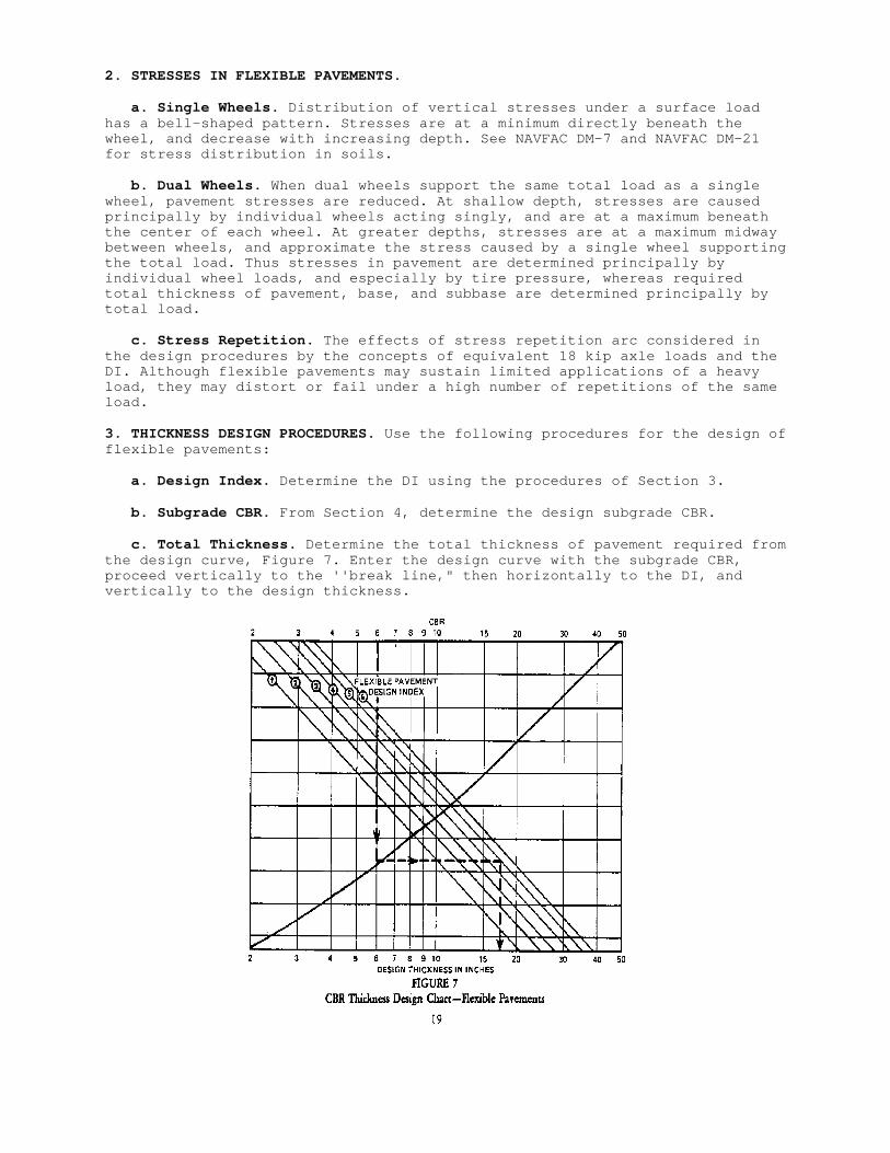
1 Flexible Pavement Terminology . . . . . . . . . . . . . . . . . . 2 2 Section of a Typical Soil Profile Sheet . . . . . . . . . . . . . 4 3 Approximate Relationship Between CBR and K. . . . . . . . . . . . 8 4 Load Equivalency Factors. . . . . . . . . . . . . . . . . . . . .10 5 Typical Details of Subgrade Drainage Installations. . . . . . . .14 6 Typical Details of Base Drain Installations . . . . . . . . . . .17 7 CBR Thickness Design Chart--Flexible Pavements. . . . . . . . . .19 8 Liquid Asphalts--New and Old Grades . . . . . . . . . . . . . . .22 9 Selection Guide for Asphalt Cement. . . . . . . . . . . . . . . .2510 Average Relationship Between Compressive Strength of 6 x 12 Inch Cylinder and Flexural Strength of Beams Tested by Third-Point Loadings. . . . . . . . . . . . . . . . . . . . . . . . . . . .3111 Design Curves for Concrete Pavement Thickness (Highways). . . . .3212 Tack Coat Quantity as Related to Pavement Surface Texture . . . .42
TABLES
Table Title Page
1 Types of Bituminous Surfaces. . . . . . . . . . . . . . . . . . . 3 2 Soil Characteristics Pertinent to Roads and Airfields . . . . . . 5 3 Subgrade Sampling and Testing Standards . . . . . . . . . . . . . 7 4 Example of Computation of Equivalent 18 Kip Axle Load (EAL). . . 10 5 Vehicular Traffic Design Index. . . . . . . . . . . . . . . . . .11 6 Drybound Macadam Base . . . . . . . . . . . . . . . . . . . . . .18 7 Waterbound Macadam Base . . . . . . . . . . . . . . . . . . . . .18 8 Specialized Terminology for Bituminous Mixes. . . . . . . . . . .21 9 Specifications for Bituminous Materials . . . . . . . . . . . . .2210 Recommended Types and Grades of Bitumen for Bituminous Surfaces . 211 Bituminous Pavement Design Criteria for Us with Aggregate Blends Showing Water Absorption up to 2-1/2 Percent. . . . . . . . . .2612 Bituminous Pavement Design Criteria for Use with Aggregate Blends Showing Water Absorption up to 2-1/2 Percent . . . . . .2613 Minimum Percent Voids in Mineral Aggregate (VMA). . . . . . . . .2714 Recommended Limits for Gradation Control and Suggested Bitumen Content for Each Gradation, Bituminous Road Mixes (Surfaces). .2715 Recommended Gradings for Aggregates Used in Penetration Macadam Surfaces. . . . . . . . . . . . . . . . . . . . . . . . . . . .2816 Emulsified Asphalt Requirements for Subgrade Stabilization. . . .28
vii Change 1, SEPT 1985
Table Title Page
17 Basic Requirements for Low-Cost Roads . . . . . . . . . . . . . .3418 Representative Fabric Properties and Applications . . . . . . . .3719 Fabric Properties and Standard Test Procedures . . . . . . . . .4020 Specifications for Fabrics Used as Asphalt Overlay Reinforcement. . . . . . . . . . . . . . . . . . . . . . . . . 4321 Specifications for Subgrade Separation Fabrics Used in Flexible Pavement Construction . . . . . . . . . . . . 45
viii Change 1, SEPT 1985
Section 1. INTRODUCTION
1. SCOPE. This manual presents criteria for the design of pavements andsupporting materials for roads, parking areas, and walks. For design criteriafor soil mechanics problems associated with pavement design (such asconsolidation and stability of compressible or weak subsoils underlying fills,and soil compaction procedures), see Soil Mechanics, Foundations, and EarthStructures, NAVFAC DM-7. For additional criteria on traffic speeds, useclassification and loads, geometry, and related factors applicable to roadsand parking areas; see General Provisions and Geometric Design for Roads,Streets, Walks, and Open Storage Areas, NAVFAC DM-5.5. Pavement designcriteria given in this manual should be supplemented or modified by localstate highway department practices, where investigation has shown that theyare adequate and economical or are required for local conditions.
2. RELATED CRITERIA. Criteria for the design of some features related topavements are delineated in this and other manuals in the design manualsseries, as cited below:
Subject Source
Structural Engineering . . . . . . . . . . . . . . . . . . . . NAVFAC DM-2Bridge pavementHydrology and Hydraulics . . . . . . . . . . . . . . . . . . . NAVFACDM-5.2 Surface drainage Subsurface drainageDrainage Systems . . . . . . . . . . . . . . . . . . . . . . . NAVFACDM-5.3 Surface drainage Subsurface drainageSoil Mechanics, Foundations, and Earth Structures. . . . . . . NAVFAC DM-7 Soil exploration, identification, and testing Subsurface drainageAirfield Pavements . . . . . . . . . . . . . . . . . . . . . . NAVFAC DM-21 Airfield pavements Subsurface drainage
3. CANCELLATION. This manual, Pavements, NAVFAC DM-5.4, cancels and supersedesChapter 4, Civil Engineering, NAVFAC DM-5, of April 1974.
4. PAVEMENT TYPES. Both rigid and flexible pavements are satisfactory forroads, streets, and parking areas.
a. Rigid Pavements. Rigid pavements are constructed of a portland cementconcrete surfacing and usually include a granular base course. Rigid pavementsare resistant to petroleum products and should be used in vehicle fueling andservice areas. Consider using rigid pavements in areas designated formotorcycle parking where high unit loads on kickstands may distort flexiblepavement in hot weather.
b. Flexible Pavements. The term flexible pavement refers to all pavementtypes having a bituminous surface. For most types of road construction,flexible pavement is preferred due to lower initial cost. Flexible-typepavements are more readily adaptable to stage construction and may also bemore suitable where settlements are expected.
1
5. PAVEMENTS COMPONENTS.
a. Rigid Pavements. Rigid pavements are usually composed of a concretesurfacing and granular base on a prepared subgrade. For most types of roadconstruction, the surfacing is unreinforced. The base course is composed ofselect granular material or granular material stabilized with cement, bitumen,or lime. In some cases, when constructing rigid pavements on high qualitysubgrades, the base may not be required.
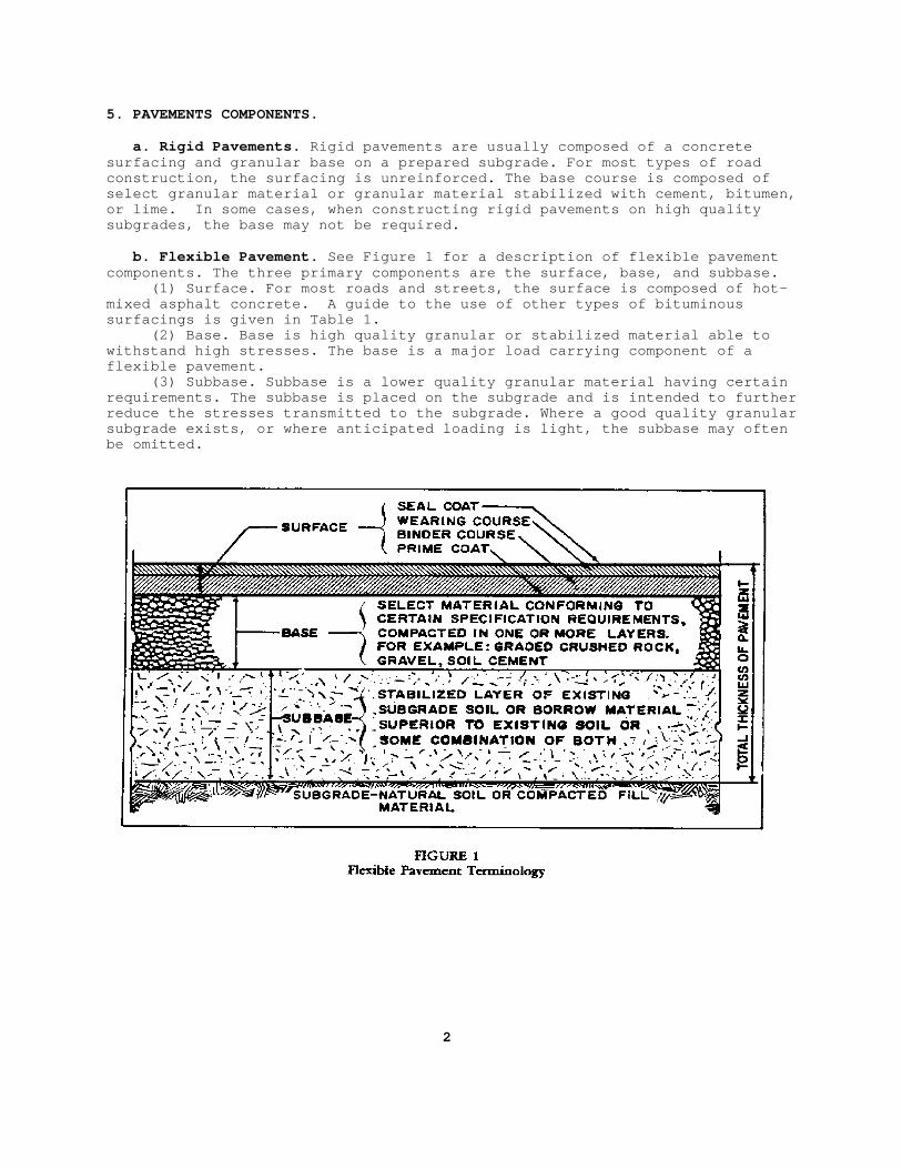
b. Flexible Pavement. See Figure 1 for a description of flexible pavementcomponents. The three primary components are the surface, base, and subbase. (1) Surface. For most roads and streets, the surface is composed of hot-mixed asphalt concrete. A guide to the use of other types of bituminoussurfacings is given in Table 1. (2) Base. Base is high quality granular or stabilized material able towithstand high stresses. The base is a major load carrying component of aflexible pavement. (3) Subbase. Subbase is a lower quality granular material having certainrequirements. The subbase is placed on the subgrade and is intended to furtherreduce the stresses transmitted to the subgrade. Where a good quality granularsubgrade exists, or where anticipated loading is light, the subbase may oftenbe omitted.
2
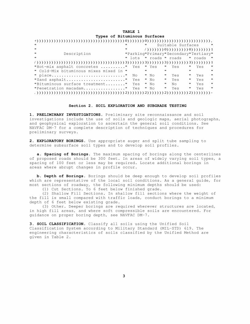
TABLE 1 Types of Bituminous Surfaces +))))))))))))))))))))))))))))))))))))0)))))))0)))))))))))))))))))))))))), * * * Suitable Surfaces * * * /)))))))0)))))))))0))))))))1 * Description *Parking*Primary*Secondary*Tertiary* * * lots * roads * roads * roads * /))))))))))))))))))))))))))))))))))))3)))))))3)))))))3)))))))))3))))))))1 *Hot-mix asphalt concretes ..........* Yes * Yes * Yes * Yes * * Cold-Mix bituminous mixes mixed in * * * * * * place..............................* No * No * Yes * Yes * *Sand asphalt........................* Yes * No * Yes * Yes * *Bituminous surface treatment........* Yes * No * No * Yes * *Penetration macadam.................* Yes * No * Yes * Yes * .))))))))))))))))))))))))))))))))))))2)))))))2)))))))2)))))))))2))))))))-
Section 2. SOIL EXPLORATION AND SUBGRADE TESTING
1. PRELIMINARY INVESTIGATIONS. Preliminary site reconnaissance and soilinvestigations include the use of soils and geologic maps, aerial photographs,and geophysical exploration to ascertain the general soil conditions. SeeNAVFAC DM-7 for a complete description of techniques and procedures forpreliminary surveys.
2. EXPLORATORY BORINGS. Use appropriate auger and split tube sampling todetermine subsurface soil types and to develop soil profiles.
a. Spacing of Borings. The maximum spacing of borings along the centerlinesof proposed roads should be 300 feet. In areas of widely varying soil types, aspacing of 100 feet or less may be required. Locate additional borings inareas where abrupt changes in profile occur.
b. Depth of Borings. Borings should be deep enough to develop soil profileswhich are representative of the local soil conditions. As a general guide, formost sections of roadway, the following minimum depths should be used: (1) Cut Sections. To 6 feet below finished grade. (2) Shallow Fill Sections. In shallow fill sections where the weight ofthe fill is small compared with traffic loads, conduct borings to a minimumdepth of 6 feet below existing grade. (3) Other. Deeper borings are required wherever structures are located,in high fill areas, and where soft compressible soils are encountered. Forguidance on proper boring depth, see NAVFAC DM-7.
3. SOIL CLASSIFICATION. Classify all soils using the Unified SoilClassification System according to Military Standard (MIL-STD) 619. Theengineering characteristics of soils classified by the Unified Method aregiven in Table 2.
3
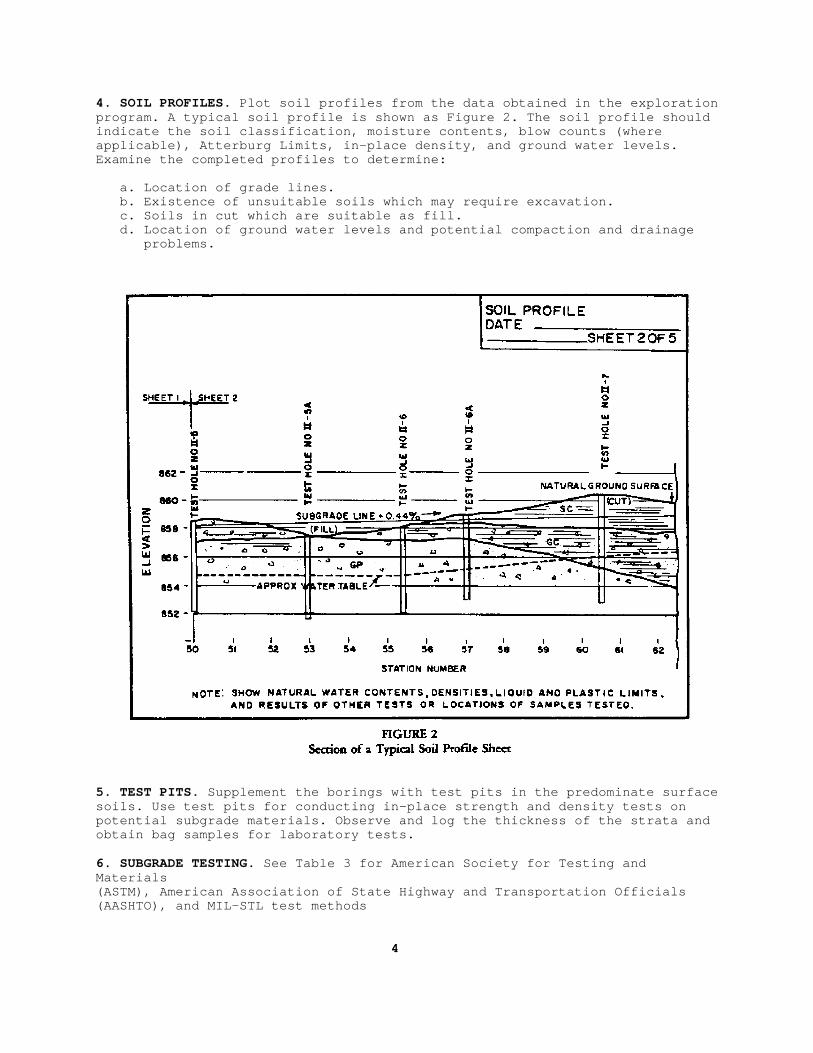
4. SOIL PROFILES. Plot soil profiles from the data obtained in the explorationprogram. A typical soil profile is shown as Figure 2. The soil profile shouldindicate the soil classification, moisture contents, blow counts (whereapplicable), Atterburg Limits, in-place density, and ground water levels.Examine the completed profiles to determine:
a. Location of grade lines. b. Existence of unsuitable soils which may require excavation. c. Soils in cut which are suitable as fill. d. Location of ground water levels and potential compaction and drainage problems.
5. TEST PITS. Supplement the borings with test pits in the predominate surface soils. Use test pits for conducting in-place strength and density tests on potential subgrade materials. Observe and log the thickness of the strata and obtain bag samples for laboratory tests.
6. SUBGRADE TESTING. See Table 3 for American Society for Testing andMaterials (ASTM), American Association of State Highway and Transportation Officials (AASHTO), and MIL-STL test methods
4

CCB IS UNABLE TO REPRODUCE FOLD-OUT PAGES FROM ORIGINAL DOCUMENTS - TABLE 2 Soil Characteristics Pertinent to Roads and Airfields - NOT INCLUDED.
5

PAGE 6 INTENTIONALLY BLANK
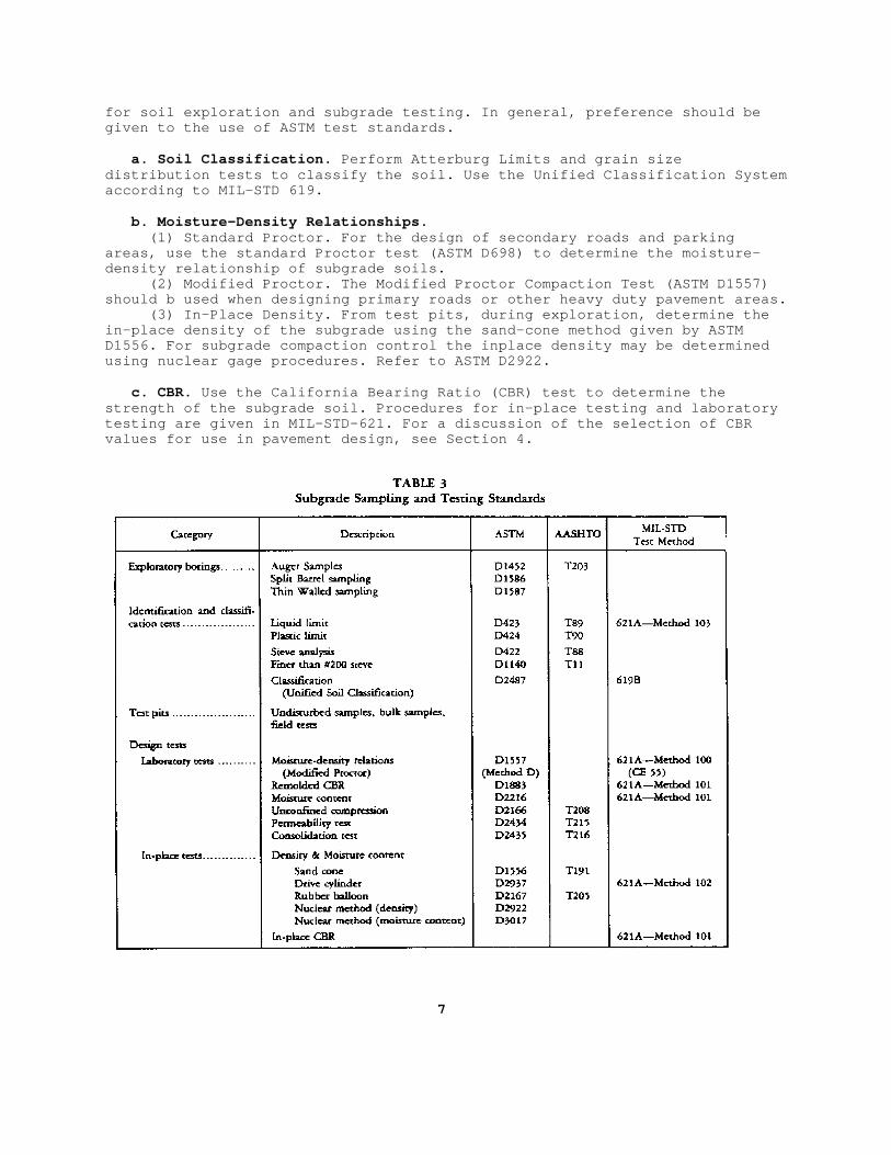
for soil exploration and subgrade testing. In general, preference should begiven to the use of ASTM test standards.
a. Soil Classification. Perform Atterburg Limits and grain sizedistribution tests to classify the soil. Use the Unified Classification Systemaccording to MIL-STD 619.
b. Moisture-Density Relationships. (1) Standard Proctor. For the design of secondary roads and parkingareas, use the standard Proctor test (ASTM D698) to determine the moisture-density relationship of subgrade soils. (2) Modified Proctor. The Modified Proctor Compaction Test (ASTM D1557)should b used when designing primary roads or other heavy duty pavement areas. (3) In-Place Density. From test pits, during exploration, determine thein-place density of the subgrade using the sand-cone method given by ASTMD1556. For subgrade compaction control the inplace density may be determinedusing nuclear gage procedures. Refer to ASTM D2922.
c. CBR. Use the California Bearing Ratio (CBR) test to determine thestrength of the subgrade soil. Procedures for in-place testing and laboratorytesting are given in MIL-STD-621. For a discussion of the selection of CBRvalues for use in pavement design, see Section 4.
7
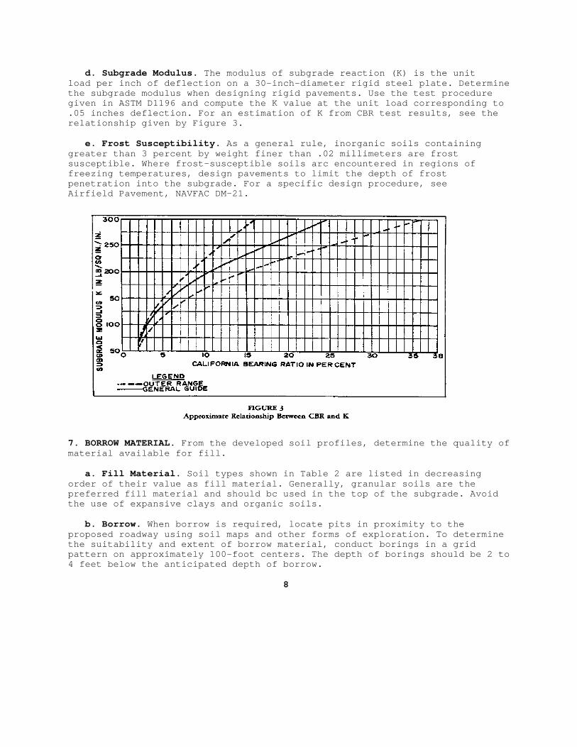
d. Subgrade Modulus. The modulus of subgrade reaction (K) is the unitload per inch of deflection on a 30-inch-diameter rigid steel plate. Determinethe subgrade modulus when designing rigid pavements. Use the test proceduregiven in ASTM D1196 and compute the K value at the unit load corresponding to.05 inches deflection. For an estimation of K from CBR test results, see therelationship given by Figure 3.
e. Frost Susceptibility. As a general rule, inorganic soils containinggreater than 3 percent by weight finer than .02 millimeters are frostsusceptible. Where frost-susceptible soils arc encountered in regions offreezing temperatures, design pavements to limit the depth of frostpenetration into the subgrade. For a specific design procedure, seeAirfield Pavement, NAVFAC DM-21.
7. BORROW MATERIAL. From the developed soil profiles, determine the quality ofmaterial available for fill.
a. Fill Material. Soil types shown in Table 2 are listed in decreasingorder of their value as fill material. Generally, granular soils are thepreferred fill material and should bc used in the top of the subgrade. Avoidthe use of expansive clays and organic soils.
b. Borrow. When borrow is required, locate pits in proximity to theproposed roadway using soil maps and other forms of exploration. To determinethe suitability and extent of borrow material, conduct borings in a gridpattern on approximately 100-foot centers. The depth of borings should be 2 to4 feet below the anticipated depth of borrow.
8
c. Base and Subbase Materials. Suitable materials for base and subbase arefrequently available on Government-owned land. Determine the cost of process-ing available materials against the cost of commercial sources.
Section 3. TRAFFIC ANALYSIS
1. TRAFFIC SURVEYS. Traffic surveys should be conducted to determine thenumber and weight of the vehicles anticipated to use the pavement in question.The prediction of traffic intensity should include the present volumes modi-fied by an appropriate factor for growth. Rely on local practice or the prac-tice of the state highway department for specific procedures for conductingsurveys. Guidance on traffic studies for military installations is containedin Military Traffic Management Command Pamphlet No. 55-8, "Traffic EngineeringStudy Reference." When designing new roads and streets, consider trafficrequirements for a 20-year design period.
a. Average Daily Traffic. Determine the average daily traffic (ADT) fromavailable records or vehicle counts for the road under consideration or for anexisting roadway of similar traffic conditions. Where data is not available, adetailed traffic study may be required.
b. Traffic Weight. The percentage of trucks (T) in a traffic stream shouldbe determined by traffic counts or current records. A tabulation of the numberof axles observed within certain load groups should be made using the FederalHighway Administration loadometer tables.
c. Equivalent 18 Kip Repetitions. The basic method of measuring the effectsof mixed traffic on highway pavements is with the use of equivalent 18 kipsingle-axle loads (EAL). The concept of the equivalent axle load was developedfrom the AASHTO Road Test. A detailed discussion on the development of the load equivalency factors is contained in AASHO Interim Guide for Design ofPavement Structures--1972.[1] Load equivalency factors for single and tandemaxle loads are given by Figure 4. For an example of their use see Table 4.
d. Traffic Distribution. Assign 50 percent of the total two-way traffic toeach direction. For two-lane roads 100 percent of the unidirectional trafficis assigned to the design lane. For four-lane roads 90 percent of the unidir-ectional traffic should be assigned to the outside lane.
2. DESIGN INDEX. A design index (DI) is used in the flexible pavement thick-ness design procedures to account for the effects of traffic intensity andweight.
a. Vehicle Groups. Where detailed traffic survey and axle load data are notavailable, spot counts or estimates can be made to ascertain the generalcharacteristics and volume of traffic. As an aid to determining a DI, vehiclesshould be grouped according to the following categories: (1) Group 1: Passenger cars and panel and pickup trucks. (2) Group 2: Two-axle trucks. (3) Group 3: Trucks having three or more axles.
b. Selection of Design Index. From detailed traffic surveys or generalvehicle groups given above, select the DI from Table 5.
c. Design Index for Tracked Vehicles and Forklift Trucks. The DIs given inTable 5 do not include the effects of tracked vehicles or forklift trucks.Where significant volumes of tracked vehicles and forklifts are indicated, ahigher DI may be required for thickness design. Procedures for consideringthese exceptional vehicles are contained in Flexible Pavements for Roads,Streets, Walks, and Open Storage Areas, DA TM5-822-5.))))))))))))))))[1] The American Association of State Highway Officials, AASHO, was renamedAmerican Association of State Highway and Transportation Officials in 1973.
9
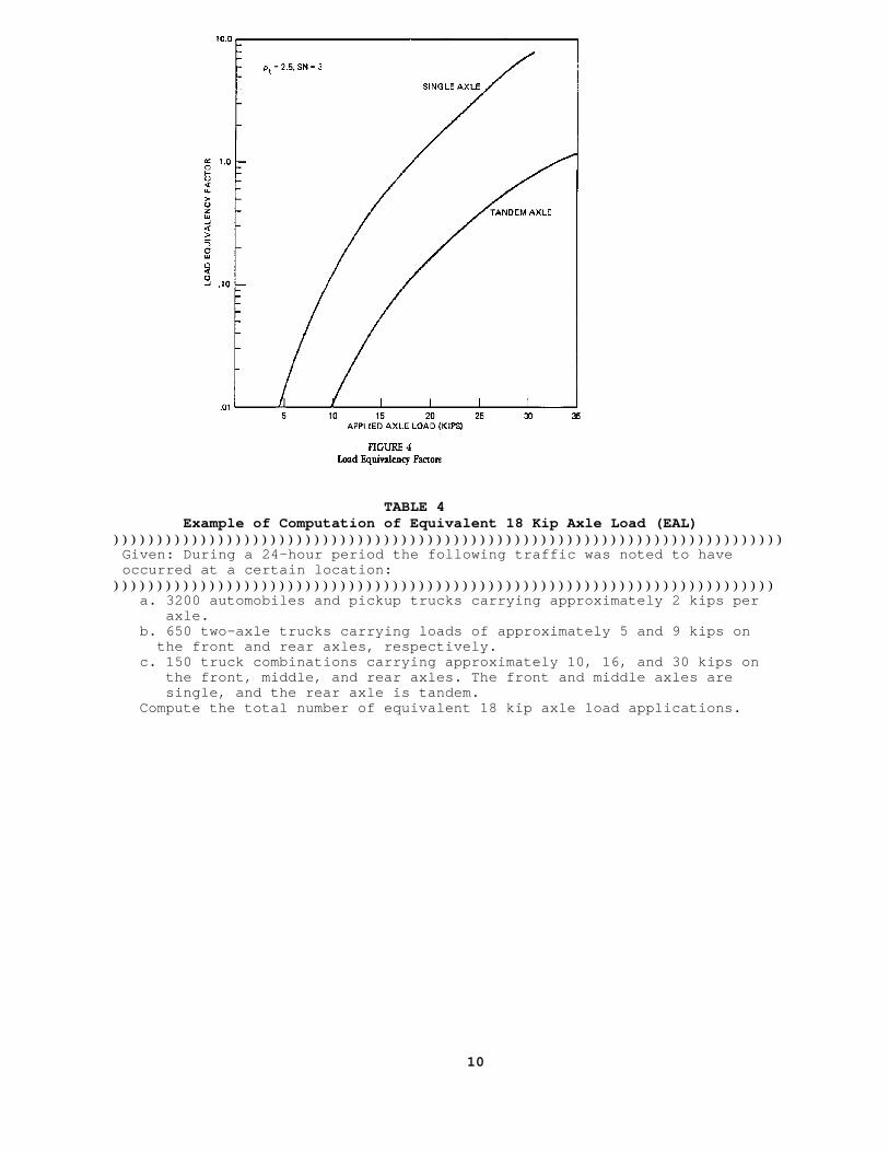
TABLE 4 Example of Computation of Equivalent 18 Kip Axle Load (EAL) ))))))))))))))))))))))))))))))))))))))))))))))))))))))))))))))))))))))))))))) Given: During a 24-hour period the following traffic was noted to have occurred at a certain location: )))))))))))))))))))))))))))))))))))))))))))))))))))))))))))))))))))))))))))) a. 3200 automobiles and pickup trucks carrying approximately 2 kips per axle. b. 650 two-axle trucks carrying loads of approximately 5 and 9 kips on the front and rear axles, respectively. c. 150 truck combinations carrying approximately 10, 16, and 30 kips on the front, middle, and rear axles. The front and middle axles are single, and the rear axle is tandem. Compute the total number of equivalent 18 kip axle load applications.
10
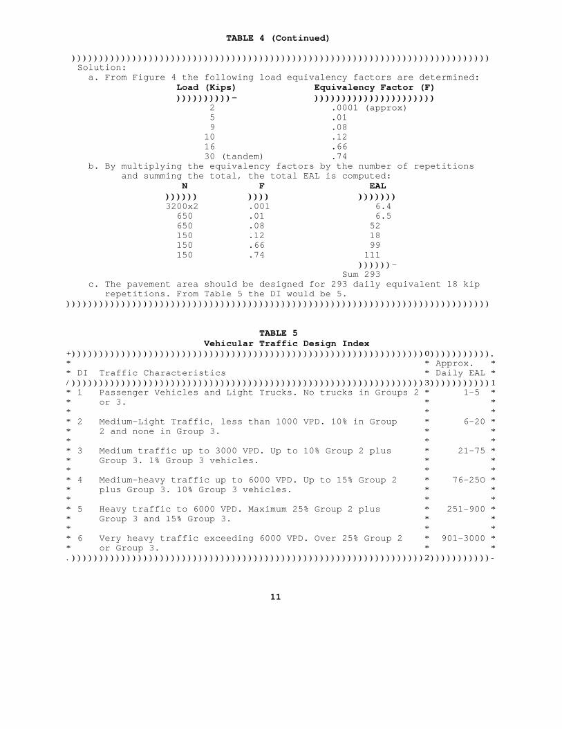
TABLE 4 (Continued) )))))))))))))))))))))))))))))))))))))))))))))))))))))))))))))))))))))))))))) Solution: a. From Figure 4 the following load equivalency factors are determined: Load (Kips) Equivalency Factor (F) ))))))))))))))))))))- )))))))))))))))))))))))))))))))))))))))))))) 2 .0001 (approx) 5 .01 9 .08 10 .12 16 .66 30 (tandem) .74 b. By multiplying the equivalency factors by the number of repetitions and summing the total, the total EAL is computed: N F EAL )))))))))))) )))))))) )))))))))))))) 3200x2 .001 6.4 650 .01 6.5 650 .08 52 150 .12 18 150 .66 99 150 .74 111 ))))))- Sum 293 c. The pavement area should be designed for 293 daily equivalent 18 kip repetitions. From Table 5 the DI would be 5. )))))))))))))))))))))))))))))))))))))))))))))))))))))))))))))))))))))))))))))
TABLE 5 Vehicular Traffic Design Index +))))))))))))))))))))))))))))))))))))))))))))))))))))))))))))))))0))))))))))),* * Approx. ** DI Traffic Characteristics * Daily EAL */))))))))))))))))))))))))))))))))))))))))))))))))))))))))))))))))3)))))))))))1* 1 Passenger Vehicles and Light Trucks. No trucks in Groups 2 * 1-5 ** or 3. * ** * ** 2 Medium-Light Traffic, less than 1000 VPD. 10% in Group * 6-20 ** 2 and none in Group 3. * ** * ** 3 Medium traffic up to 3000 VPD. Up to 10% Group 2 plus * 21-75 ** Group 3. 1% Group 3 vehicles. * ** * ** 4 Medium-heavy traffic up to 6000 VPD. Up to 15% Group 2 * 76-25O ** plus Group 3. 10% Group 3 vehicles. * ** * ** 5 Heavy traffic to 6000 VPD. Maximum 25% Group 2 plus * 251-900 ** Group 3 and 15% Group 3. * ** * ** 6 Very heavy traffic exceeding 6000 VPD. Over 25% Group 2 * 901-3000 ** or Group 3. * *.))))))))))))))))))))))))))))))))))))))))))))))))))))))))))))))))2)))))))))))-
11
Section 4. SUBGRADES
1. EXPLORATION. Sec Section 2 of this manual for criteria for subgrade explor-ation, identification, and testing. Additional criteria for the determinationof the design subgrade strength is given below.
2. SUBGRADE STRENGTH.
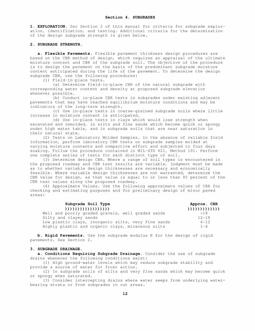
a. Flexible Pavements. Flexible pavement thickness design procedures arebased on the CBR method of design, which requires an appraisal of the ultimatemoisture content and CBR of the subgrade soil. The objective of the procedureis to design the pavement on the basis of the predominant subgrade moisturecontent anticipated during the life of the pavement. To determine the designsubgrade CBR, use the following procedures: (1) Field-in-place tests. (a) Determine field-in-place CBR of the natural subgrade withcorresponding water content and density at proposed subgrade elevationwhenever possible. (b) Conduct in-place CBR tests in subgrades under existing adjacentpavements that may have reached equilibrium moisture conditions and may beindicators of the long-term strength. (c) Use in-place tests in coarse-grained subgrade soils where littleincrease in moisture content is anticipated. (d) Use in-place tests in clays which would lose strength whenexcavated and remolded, in silts and fine sands which become quick or spongyunder high water table, and in subgrade soils that are near saturation intheir natural state. (2) Tests on Laboratory Molded Samples. In the absence of reliable fieldinformation, perform laboratory CBR tests on subgrade samples molded atvarying moisture contents and compactive effort and subjected to four dayssoaking. Follow the procedure contained in MIL-STD 621, Method 101. Performone complete series of tests for each distinct type of soil. (3) Determine design CBR. Where a range of soil types is encountered inthe proposed roadway and CBR test results are variable, judgment must be madeas to whether variable design thicknesses are necessary and economicallyfeasible. Where variable design thicknesses are not warranted, determine theCBR value for design, as that value is equal to or less than 85 percent of theCBR test values along the proposed roadway. (4) Approximate Values. Use the following approximate values of CBR forchecking and estimating purposes and for preliminary design of minor pavedareas:
Subgrade Soil Type Approx. CBR )))))))))))))))))))))))))))))))))))) )))))))))))))))))))))))))) Well and poorly graded gravels, well graded sands >18 Silty and clayey sands 12-18 Low plastic clays, inorganic silts, very fine sands 6-12 Highly plastic and organic clays, micaceous silts 1-6
b. Rigid Pavements. Use the subgrade modulus K for the design of rigidpavements. See Section 2.
3. SUBGRADE DRAINAGE. a. Conditions Requiring Subgrade Drainage. Consider the use of subgradedrains whenever the following conditions exist: (1) High ground-water levels which may reduce subgrade stability andprovide a source of water for frost action. (2) In subgrade soils of silts and very fine sands which may become quickor spongy when saturated. (3) Consider intercepting drains where water seeps from underlying water-bearing strata or from subgrades in cut areas.
12
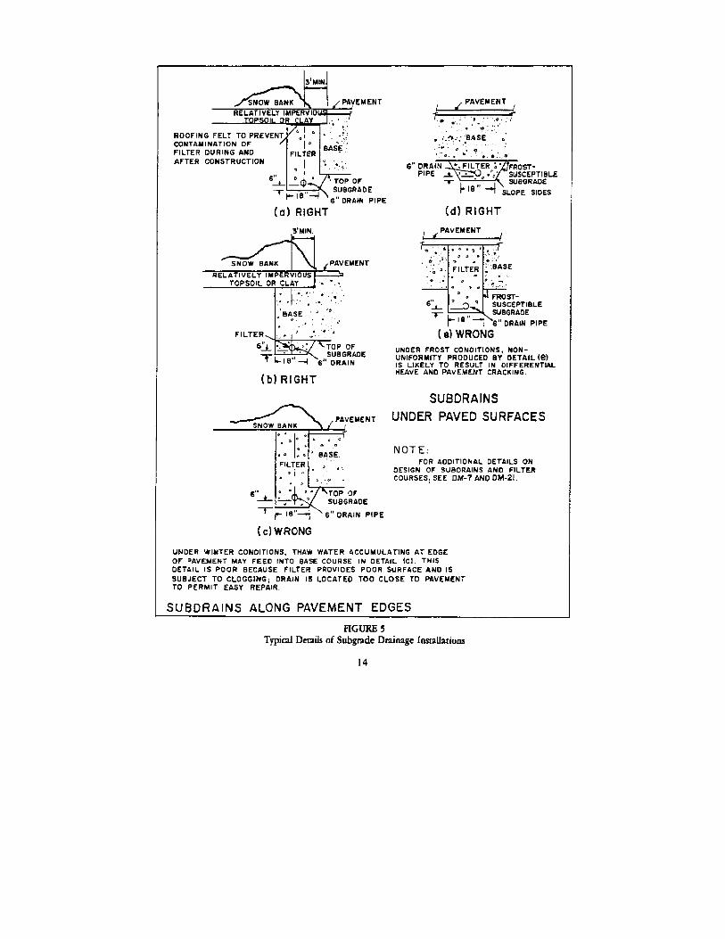
b. Design Details. Use subsurface drains (perforated collector pipes andfilters) in lieu of deep ditches for collecting and transporting ground water.For typical subgrade drain installation, see Figure 5. For design criteria seeNAVFAC DM-7 and NAVFAC DM-21.
4. SUBGRADE COMPACTION.
a. Fill Sections. All granular fill materials should be compacted to atlest 95 percent of maximum density. Cohesive fill material should be completedto no less than 90 percent.
b. Cut Sections. In cut, the depth and degree of compaction required varieswith the pavement design index. Specific guidance on compaction depth is givenin DA TM 5-822-5. When existing subgrade soils do not meet minimum compactionrequirements, consider the following alternatives: (1) Compact soils from the surface. (2) Remove and process soil to attain the approximate optimum moistureand replace and compact. (3) Replace subgrade soil with suitable borrow material. (4) Raise the grade so that existing natural densities meet required values.
5. SETTLEMENT. When designing roadways in fill sections, examine soil profilesto ascertain possible settlement due to the existence of compressible layers.For settlement analysis, see NAVFAC DM-7.
6. SUBGRADE STABILIZATION. Native subgrade and lower quality borrow materialsmay be improved for use in the pavement structure with the use of a cement,bitumen, or lime stabilizing agent. For stabilization or modification ofcohesive subgrade soils, hydrated lime is the most widely used. Lime isapplicable in clay soils (CH, CL) and in granular soils containing clay binder(GC, SC). Lime reduces the plasticity index (PI) and renders a clay soil lesssensitive to moisture changes. Consider the use of lime whenever the PI of thesoil is greater than 10.
a. Lime Treatment. Lime treatment or modification consists of theapplication of from 1 to 3 percent hydrated lime to aid drying of the soil andpermit compaction. As such it is useful in the construction of a "workingplatform" to expedite construction. Lime modification may also be consideredto condition a soil for follow-on stabilization with cement or bitumen. Limetreatment of subgrade soils is intended to expedite construction, and noreduction in the required pavement thickness should be made.
b. Lime Stabilization. For lime stabilization of clay subgrades, the limecontent should be from 3 percent to 8 percent of the dry weight of the soil,and the cured mass should have an unconfined compressive strength of at least50 psi in 28 days. The optimum lime content should be determined with the useof unconfined compression and Atterburg Limits tests on laboratory lime-soilmixtures molded at varying percentages of lime. Determine the laboratory CBRof the optimum lime soil mixture for use in pavement thickness designprocedures.
Section 5. SUBBASE
1. FUNCTIONS AND REQUIREMENTS. a. Rigid Pavements. Subbase normally is not used in rigid pavements. Thecourse directly beneath the concrete is termed "base."
b. Flexible Pavements. In flexible pavements, the subbase is composed of aselected borrow or stabilized material used to reduce the thickness of thebase. The subbase is placed on the subgrade and serves as a load-distributingmedium to reduce subgrade stress.
13
2. MATERIALS. Subbase materials can consist of any of the following:
a. Naturally occurring course-grained soils such as gravel, well-gradedsands, and disintegrated granite. b. Naturally occurring and processed materials such as limerock, coral,caliche, quarry and mine wastes, slag, shell, and sand-shell mixtures. c. Naturally occurring or processed materials which are stabilized withcement, lime, or bitumen. d. Mechanically stabilized mixtures in which borrow or processed materialsare blended with on-site soils to form a more dense and stable layer.Mechanical stabilization of subgrade soils may be used only where the liquidlimit (LL) and PI of the existing soil meet the requirements for subbase.
3. SUBBASE CBR.
a. Laboratory Tests. Perform laboratory CBR tests on remolded soakedsamples as outlined in MIL-STD 621, Method 101. Laboratory CBR tests are to besupplemented with grain size and plasticity requirements to arrive at a CBRvalue for design. Where proposed subbase materials exist in place undersimilar conditions, the in-place CBR value should be determined and used fordesign. b. Maximum design CBR. When laboratory CBR values have been determined, themaximum value for use in design may be controlled by the following gradationand plasticity limitations:
Max. Permissible Gradation, Max. % Passing Design CBR Max. Size #10 Sieve #200 Sieve Max. LL Max. PI)))))))))))))))))))))))))))))))))))))))))))))))))))))))))))))))))))))))))))))))))))))))))))))))))))))))))))))))))))))))))))))))))))))))))))))))))))) 50 3" 50 15 25 5 40 3" 80 15 25 5 30 3" 100 15 25 5
For additional general requirements and recommended gradations of subbasematerials, see "AASHTO Specification M-147" in Standard Specifications forTransportation Materials and Methods for Sampling and Testing.
4. COMPACTION. Compact all granular subbase course materials to 100 percentof maximum density.
Section 6. BASE
1. FUNCTIONS AND REQUIREMENTS.
a. Rigid Pavements. Use base course under rigid pavements where subgradesdo not meet the gradation, plasticity, and CBR requirements for base. Basecourses are required under the following conditions: (1) Frost Action. Use base courses to prevent or reduce frostpenetration into subgrades. (2) Subgrade Pumping. Provide a base course over subgrade soilsclassified as CH, CL, ML, MH, and OL to prevent pumping. (3) Uneven Support. Provide base courses to provide uniform support topavement slabs. (4) High Volume Change Subgrade Soils. Provide base courses asoverburden on expansive soils to minimize potential heaving and faulting atjoints. b. Flexible Pavements. A base course is a major load-carrying component ina flexible pavement. The base must have high structural strength and bedensely compacted.
15
2. BASE DRAINAGE.
a. Conditions Requiring Drainage. Consider the use of a base coursedrainage system wherever the following conditions exist: (1) Where ground water levels approach the bottom of the base. (2) Where frost action penetrates the subgrade. (3) In sag vertical curves where the subgrade soil has low permeability.
b. Design Details. For typical basic drainage details, see Figure 6. Fordesign criteria for subdrains filter materials see NAVFAC DM-7. For drainagecomputation procedures, see NAVFAC DM-21.
3. BASES FOR RIGID PAVEMENT.
a. Materials. Materials used as a subbase in flexible pavements aresuitable for base courses in rigid pavements. Refer to Section 5.
b. Gradation and Plasticity. Base materials should be well graded,conforming to AASHTO Specification M-147. The LL should be no greater than 25and the PI no greater than 5.
c. CBR. The minimum required CBR is 30.
d. Thickness. The minimum thickness of granular base should be 6 inches.Thicker bases may be required in order to reduce frost penetration into thesubgrade or to increase K modulus value in weak subgrade soils. For thicknessdesign procedures for base courses, see NAVFAC DM-21.
e. Compaction. Base courses under rigid pavements should be compacted to atleast 95 percent of maximum density.
4. BASES FOR FLEXIBLE PAVEMENTS.
a. Materials. The selection of a base course material for flexible pave-ments should be based on the economic availability. Generally the followingnatural and processed materials can be used as base: Crushed or uncrushed gravel Graded crushed rock Waterbound macadam Drybound macadam Limerock Coral Sand-shell Blast furnace slag Cement, bitumen, or lime stabilized soil mixtures
b. Gradation and Plasticity. Recommended gradations for drybound andwaterbound macadam bases are given in Graded Aggregate Base Course forFlexible Pavement, TS-02686. For other local materials including limerock,sand-shell, and coral, use locally available and proven gradations. For allbase types for flexible pavements the LL should be no greater than 25 and thePI no greater than 5.
c. Design CBR. For flexible pavement thickness design, use the followingCBR values, without testing, for the following materials: Base Type Design CBR ---------------------------------------------------------------- Graded, Crushed Aggregate 100 Waterbound Macadam 100 Drybound Macadam 100 Cement- and Asphalt-treated Aggregate 100 Limerock 80 Sand-shell 80 Coral 80
16
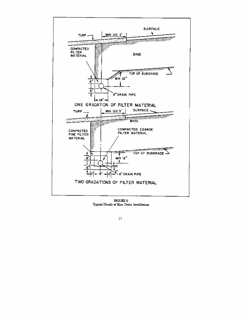
TABLE 6 Drybound Macadam Base+))))))))))))))0)))))))))))))))))))))))))))))))))))))))))))))))))))))))))))),* * Percentage by weight passing square mesh sieve ** /)))))))))))))))))))))))))))))))))))0))))))))))))))))0)))))))1* * *Choker aggregate*Screen-** Sieve * Coarse--aggregate gradation * graduation * ings ** designation /))))))))0))))))))0))))))))0))))))))3)))))))0))))))))3)))))))1 * * No 1 * No 2 * No 3 * No 4 * No 5 * No 6 * No 7 */))))))))))))))3))))))))3))))))))3))))))))3))))))))3)))))))3))))))))3)))))))1* 3" * 100 * 100 * --- * --- * --- * --- * --- ** 2-1/2" * 90-100 * 90-100 * 100 * --- * --- * --- * --- ** 2" * 35-70 * --- * 90-100 * 100 * --- * --- * --- ** 1-1/2" * 0-15 * 25-60 * 35-70 * 90-100 * --- * --- * --- ** 1" * --- * --- * 0-15 * 20-55 * --- * --- * --- ** 3/4" * 0-5 * 0-10 * --- * 0-15 * 100 * --- * --- ** 1/2" * --- * 0-5 * 0-5 * --- * 90-100* --- * --- ** 3/8" * --- * --- * --- * 0-5 * --- * 100 * 100 ** No. 4 * --- * --- * --- * --- * --- * 85-100 * 85-100** No. 100 * --- * --- * --- * --- * 10-30 * 10-30 * 5-25 *.))))))))))))))2))))))))2))))))))2))))))))2))))))))2)))))))2))))))))2)))))))-
TABLE 7 Waterbound Macadam Base +))))))))))))))))))))))))))))))))))))))))))))))))))))))))))))))))))))), * Percentage by weight passing square mesh sieve * /))))))))))))))0))))))))))))))))))))))))))))0)))))))))))))))))))))))))1 * Sieve *Coarse--aggregate gradation * Screenings gradation * * designation /))))))))0)))))))))0)))))))))3)))))))))))0)))))))))))))1 * * No 1 * No 2 * No 3 * No 4 * No 5 * /))))))))))))))3))))))))3)))))))))3)))))))))3)))))))))))3)))))))))))))1 * 3" * 100 * 100 * --- * --- * --- * * 2-1/2" * 90-100 * 90-100 * 100 * --- * --- * * 2" * 35-70 * * 90-100 * --- * --- * * 1-1/2" * 0-15 * 25-60 * 35-70 * --- * --- * * 1" * --- * --- * 0-15 * --- * --- * * 3/4" * 0-5 * 0-10 * --- * 100 * --- * * 1/2" * --- * 0-5 * 0-5 * 90-100 * --- * * 3/8" * --- * --- * --- * --- * 100 * * No. 4 * --- * --- * --- * --- * 85-100 * * No. 100 * --- * --- * --- * 10-30 * 10-30 * .))))))))))))))2))))))))2)))))))))2)))))))))2)))))))))))2)))))))))))))-
d. Thickness. The required thickness of base should be determined using theflexible pavement thickness design procedures in Section 7. The minimum basethickness is 6 inches. e. Compaction. Compact all base courses in flexible pavements to 100percent of maximum density.
Section 7. FLEXIBLE PAVEMENT THICKNESS DESIGN
1. DESIGN PRINCIPLES. The CBR method of pavement design is based on theprinciple of providing sufficient thickness and quality of pavement base andsubbase courses to prevent subgrade shear deformation under traffic. Theprocedure is largely empirical but has been validated through extensiveexperience and traffic testing of prototype pavements. The design procedurealso provides for adequate compaction of the subgrade and each course toprevent settlement under traffic. Where freezing temperatures occur, thedesign procedure must give consideration to the depth of frost penetration andsubgrade weakening during the thaw period.
18
2. STRESSES IN FLEXIBLE PAVEMENTS.
a. Single Wheels. Distribution of vertical stresses under a surface loadhas a bell-shaped pattern. Stresses are at a minimum directly beneath thewheel, and decrease with increasing depth. See NAVFAC DM-7 and NAVFAC DM-21for stress distribution in soils.
b. Dual Wheels. When dual wheels support the same total load as a singlewheel, pavement stresses are reduced. At shallow depth, stresses are causedprincipally by individual wheels acting singly, and are at a maximum beneaththe center of each wheel. At greater depths, stresses are at a maximum midwaybetween wheels, and approximate the stress caused by a single wheel supportingthe total load. Thus stresses in pavement are determined principally byindividual wheel loads, and especially by tire pressure, whereas requiredtotal thickness of pavement, base, and subbase are determined principally bytotal load.
c. Stress Repetition. The effects of stress repetition arc considered inthe design procedures by the concepts of equivalent 18 kip axle loads and theDI. Although flexible pavements may sustain limited applications of a heavyload, they may distort or fail under a high number of repetitions of the sameload.
3. THICKNESS DESIGN PROCEDURES. Use the following procedures for the design offlexible pavements:
a. Design Index. Determine the DI using the procedures of Section 3.
b. Subgrade CBR. From Section 4, determine the design subgrade CBR.
c. Total Thickness. Determine the total thickness of pavement required fromthe design curve, Figure 7. Enter the design curve with the subgrade CBR,proceed vertically to the ''break line," then horizontally to the DI, andvertically to the design thickness.
d. Thickness of Base and Subbase. Enter Figure with the CBR of the subbasematerial and determine the total required thickness of base and surfacing.
e. Repeat Step d for other available subbase materials to determine themost economical combination of base and subbase material and thickness.
f. Minimum Base and Subbase. Use a minimum base thickness of 6 inches.Minimum subbase thickness should be 4 inches.
g. Minimum Thickness of Surface. Minimum thickness of asphalt concretesurfacings should be as follows:
Type of Surface Minimum Thickness (inches) )))))))))))))))))))))))))))))))))))))))))))))))))))))))))))))))))))))))))) Primary Road 3 Secondary and Tertiary Roads 2 Parking Area 2 Driveway 1.5 Sidewalk 1 Surfacing Used by Tracked Vehicles 4
Where exceptionally stable bases, such as cement-treated aggregate, naturalcementing materials (limerock), or asphalt concrete bases are used, the 2-inch minimum thickness may be reduced to 1.5 inches.
4. COMPACTION AND SETTLEMENT. Nonuniform settlement or inadequate compactionof the pavement components can result in premature pavement rutting andcracking. See requirements for subgrade compaction and settlement analysiscontained in Section 4. Subbase and base course compaction requirements arecontained in Sections 5 and 6.
5. FROST DESIGN. In areas having freezing temperatures, ascertain the need fordesigning for frost effects from state, county, or city highway departments.Determine the depth of frost penetration from the highway department or localutility companies. Use local design procedures. For a complete discussion offrost effects and two methods of design, see NAVFAC DM-21.
Section 8. DESIGN OF BITUMINOUS SURFACES
1. FUNCTIONS AND REQUIREMENTS. Bituminous surfaces provide a resilient,waterproof, load distributing medium that protects the base course against thedetrimental effects of water and the abrasive action of traffic. Bituminoussurfaces permit slight adjustments in the pavement structure, due toconsolidation, without detrimental effect, and are more readily adaptable tostage construction. The types of bituminous surfacings commonly used for roadsand streets are given in Table 1.
2. TERMINOLOGY. See Figure 1 for a description of flexible pavement componentsand see Table 8 for terminology related to bituminous mixes.
3. BITUMINOUS MATERIALS. Bituminous materials used in road constructioninclude asphalts, tars and tar-rubber blends. The applicable specificationsfor bituminous materials are given in Table 9.
a. Asphalt. Asphaltic materials are the usual choice for use in bituminouspavements due to their widespread availability and economy. Asphalticmaterials are available as asphalt cements, liquid asphalts, or emulsifiedasphalts. (1) Asphalt cements are most widely used in hot-mix asphalt concretemixtures as binder and wearing courses. The material is available in varyingdegrees of hardness (penetration) and is a solid at room temperature.
20
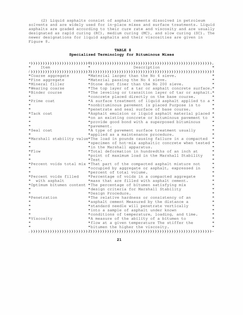
(2) Liquid asphalts consist of asphalt cements dissolved in petroleumsolvents and are widely used for in-place mixes and surface treatments. Liquidasphalts are graded according to their cure rate and viscosity and are usuallydesignated as rapid curing (RC), medium curing (MC), and slow curing (SC). Thenewer designations for liquid asphalts and their viscosities are given inFigure 8.
TABLE 8 Specialized Terminology for Bituminous Mixes
+))))))))))))))))))))))))0))))))))))))))))))))))))))))))))))))))))))))))))))),* Item * Description */))))))))))))))))))))))))3)))))))))))))))))))))))))))))))))))))))))))))))))))1*Coarse aggregate *Material larger than the No 4 sieve. **Fine aggregate *Material passing the No 4 sieve. **Mineral filler *Stone dust finer than the No 200 sieve. **Wearing coarse *The top layer of a tar or asphalt concrete surface.**Binder course *The leveling or transition layer of tar or asphalt.** *concrete placed directly on the base course. **Prime coat *A surface treatment of liquid asphalt applied to a ** *nonbituminous pavement is placed Purpose is to ** *penetrate and seal surface of base course. **Tack coat *Asphalt emulsion or liquid asphalt material placed ** *on an existing concrete or bituminous pavement to ** *provide good bond with a superposed bituminous ** *pavement. **Seal coat *A type of pavement surface treatment usually ** *applied as a maintenance procedure. **Marshall stability value*The load in pounds causing failure in a compacted ** *specimen of hot-mix asphaltic concrete when tested * * *in the Marshall apparatus. **Flow *Total deformation in hundredths of an inch at ** *point of maximum load in the Marshall Stability ** *Test. **Percent voids total mix *That part of the compacted asphalt mixture not ** *occupied by aggregate or asphalt, expressed in ** *percent of total volume. **Percent voids filled *Percentage of voids in a compacted aggregate ** with asphalt *mass that are filled with asphalt cement. **Optimum bitumen content *The percentage of bitumen satisfying mix ** *design criteria for Marshall Stability ** *Design Procedure. **Penetration *The relative hardness or consistency of an ** *asphalt cement Measured by the distance a ** *standard needle will penetrate vertically ** *into a sample of asphalt under known ** *conditions of temperature, loading, and time. **Viscosity *A measure of the ability of a bitumen to ** *flow at a given temperature The stiffer the ** *bitumen the higher the viscosity. *.))))))))))))))))))))))))2)))))))))))))))))))))))))))))))))))))))))))))))))))-
21
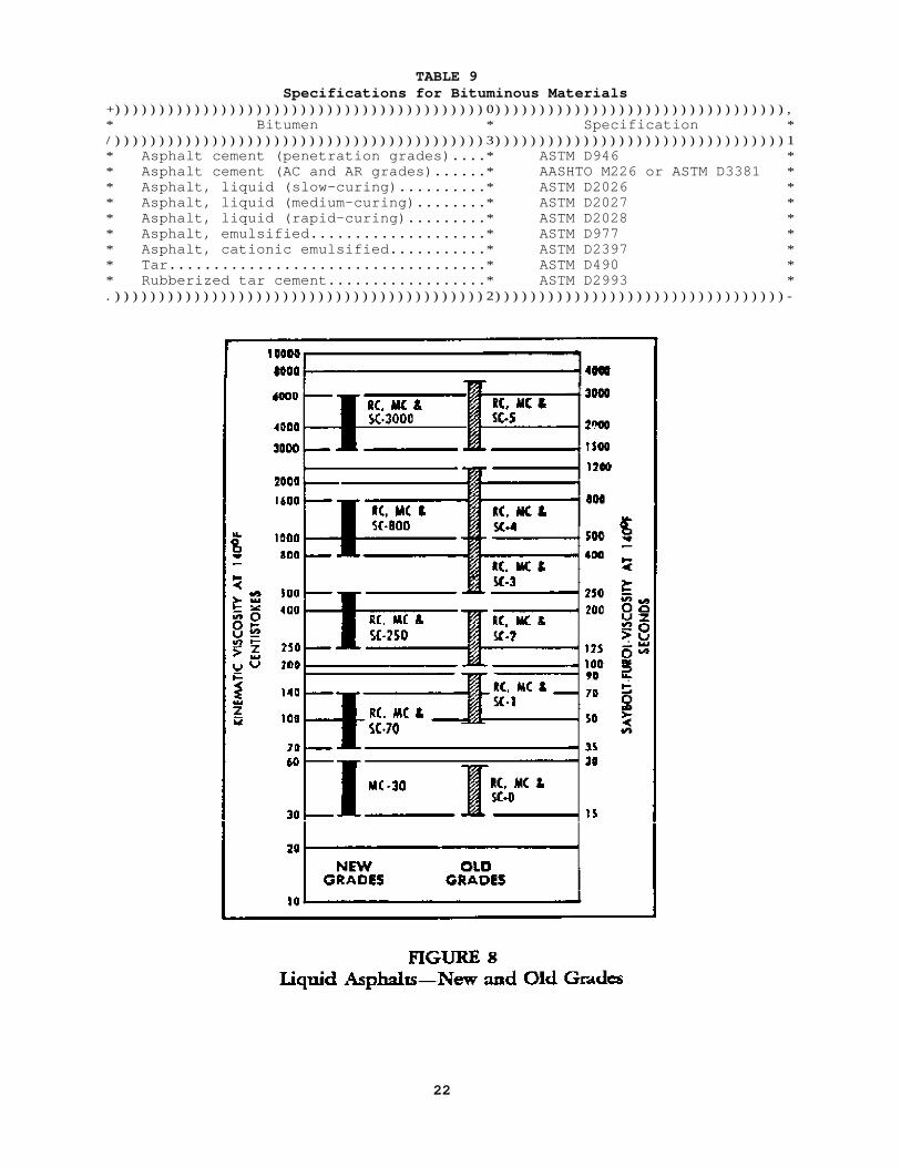
TABLE 9 Specifications for Bituminous Materials+))))))))))))))))))))))))))))))))))))))))))0))))))))))))))))))))))))))))))))),* Bitumen * Specification */))))))))))))))))))))))))))))))))))))))))))3)))))))))))))))))))))))))))))))))1* Asphalt cement (penetration grades)....* ASTM D946 ** Asphalt cement (AC and AR grades)......* AASHTO M226 or ASTM D3381 ** Asphalt, liquid (slow-curing)..........* ASTM D2026 ** Asphalt, liquid (medium-curing)........* ASTM D2027 ** Asphalt, liquid (rapid-curing).........* ASTM D2028 ** Asphalt, emulsified....................* ASTM D977 ** Asphalt, cationic emulsified...........* ASTM D2397 ** Tar....................................* ASTM D490 ** Rubberized tar cement..................* ASTM D2993 *.))))))))))))))))))))))))))))))))))))))))))2)))))))))))))))))))))))))))))))))-
22
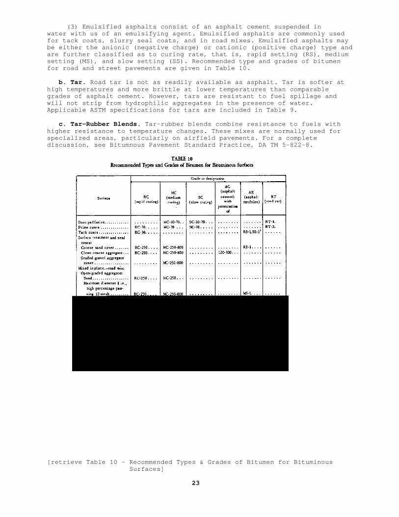
(3) Emulsified asphalts consist of an asphalt cement suspended inwater with us of an emulsifying agent. Emulsified asphalts are commonly usedfor tack coats, slurry seal coats, and in road mixes. Emulsified asphalts maybe either the anionic (negative charge) or cationic (positive charge) type andare further classified as to curing rate, that is, rapid setting (RS), mediumsetting (MS), and slow setting (SS). Recommended type and grades of bitumenfor road and street pavements are given in Table 10.
b. Tar. Road tar is not as readily available as asphalt. Tar is softer athigh temperatures and more brittle at lower temperatures than comparablegrades of asphalt cement. However, tars are resistant to fuel spillage andwill not strip from hydrophilic aggregates in the presence of water.Applicable ASTM specifications for tars are included in Table 9.
c. Tar-Rubber Blends. Tar-rubber blends combine resistance to fuels withhigher resistance to temperature changes. These mixes are normally used forspecialized areas, particularly on airfield pavements. For a completediscussion, see Bitumnous Pavement Standard Practice, DA TM 5-822-8.
[retrieve Table 10 - Recommended Types & Grades of Bitumen for Bituminous Surfaces]
23
4. AGGREGATES.
a. Suitability. Basic or alkaline rocks (limestone, dolomite), providebetter adhesion with asphaltic films than do acid or silicious rocks (granite,quartzite). Where acid rocks are used, the addition of an antistripping agentor hydrated lime may be required.
b. Coarse Aggregate. Coarse aggregates should be clean, hard, and durable.In asphaltic concrete mixtures, crushed rock is preferable for its higherstability and performance. Other requirements for coarse aggregate arecontained in ASTM D692.
c. Fine Aggregate. Fine aggregate for bituminous concrete mixes may becomposed of naturally occurring sand or of aggregate particles produced fromcrushed stone or crushed gravel. Fine aggregates should otherwise conform toASTM D1073.
d. Mineral Filler. In bituminous concrete mixtures, mineral filler shouldbe limestone dust, portland cement, or other similar inert materials. At leasttwo-thirds of the material passing the No. 200 sieve in a bituminous mixshould be nonplastic material meeting the requirements of ASTM D242.
5. BITUMINOUS MIX DESIGN.
a. Hot-Mix Asphalt Concrete. Use the Marshall mix design method for de-signing hot-mix asphalt concrete mixture. Detailed instructions for the designprocedure are contained in DA TM 5-822-8. For test methods, see MIL-STD 620. (1) Asphalt Cement. Use penetration grade, AC viscosity grade, or ARviscosity grade of asphalt cement in the mix design. Figure 9 providesrecommended grades for each area of the United States. These recommendationsshould be tempered by local practice. In areas where only the viscosity gradesare available, determine those sources having acceptable penetrations for usein the project. (2) Aggregates. Use aggregates in the mix design which meet therequirements of ASTM D692 and D1073 for coarse and fine aggregates,respectively. Mineral filler, when required, should conform to ASTM D242.Aggregates used for mix design should be identical to those anticipated to beused in construction. Gradation of aggregates should conform either to ASTMD1663 or Asphalt Binder & Wearing Courses for Flexible Pavement, NAVFAC TS-02681. In general, the maximum aggregate size for wearing courses should notexceed 3/4 inches. For binder and intermediate courses, the maximum aggregatesize should not exceed two-thirds the course thickness. (3) Marshall Requirements. Use the 75-blow compaction procedures fordesigning primary roads and streets. For secondary roads, streets, and parkingareas, use the 50-blow procedure. Follow the procedures given in DA TM5-822-8 for preparing and testing the trial mixes. Criteria for determiningthe optimum bitumen content and the adequacy of the mix are given in Tables 11and 12. A minimum bitumen content of 5 percent is recommended. (4) Optional VMA Method. This optional method of mix design utilizes theconcept of the voids in the mineral aggregate (VMA) to determine the optimumbitumen content. The VMA represents the volume of voids in the compactedaggregate mixture and includes the percent of air voids plus the effectiveasphalt content expressed as a percent of the total volume. The mix designmethod requires that a minimum volume of voids be contained in the aggregatemix in order to accommodate sufficient bitumen for stability and durability.Procedures for computing the VMA are given in Mix Design Method for AsphaltConcrete and Other Hot-Mix Types, The Asphalt Institute Publication MS-2.Criteria for minimum percent VMA are given in Table 13. In using the designprocedure, no correction is required for highly absorbent aggregate.
b. Mixed-In-Place Bituminous Pavement. Mixed-in-place bituminous pavementscan be used on secondary and other low-volume roads. The pavement shouldconsist of one layer with compacted thickness of 2 inches. For recommendedlimits for aggregate gradation and bitumen contents, see Table 14. Forrecommended grades of bitumen, see Table 10.
24
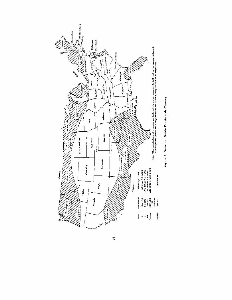
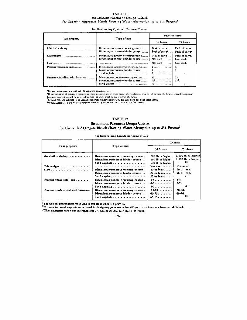
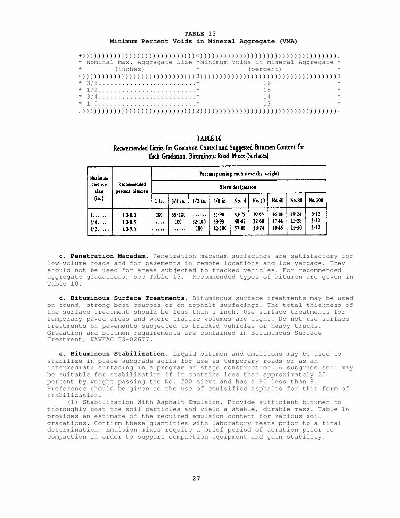
TABLE 13 Minimum Percent Voids in Mineral Aggregate (VMA)
+)))))))))))))))))))))))))))))0))))))))))))))))))))))))))))))))))), * Nominal Max. Aggregate Size *Minimum Voids in Mineral Aggregate * * (inches) * (percent) * /)))))))))))))))))))))))))))))3)))))))))))))))))))))))))))))))))))1 * 3/8.........................* 16 * * 1/2.........................* 15 * * 3/4.........................* 14 * * 1.0.........................* 13 * .)))))))))))))))))))))))))))))2)))))))))))))))))))))))))))))))))))-
c. Penetration Macadam. Penetration macadam surfacings are satisfactory forlow-volume roads and for pavements in remote locations and low yardage. Theyshould not be used for areas subjected to tracked vehicles. For recommendedaggregate gradations, see Table 15. Recommended types of bitumen are given inTable 10.
d. Bituminous Surface Treatments. Bituminous surface treatments may be usedon sound, strong base courses or on asphalt surfacings. The total thickness ofthe surface treatment should be less than 1 inch. Use surface treatments fortemporary paved areas and where traffic volumes are light. Do not use surfacetreatments on pavements subjected to tracked vehicles or heavy trucks.Gradation and bitumen requirements are contained in Bituminous SurfaceTreatment, NAVFAC TS-02677.
e. Bituminous Stabilization. Liquid bitumen and emulsions may be used tostabilize in-place subgrade soils for use as temporary roads or as anintermediate surfacing in a program of stage construction. A subgrade soil maybe suitable for stabilization if it contains less than approximately 25percent by weight passing the No. 200 sieve and has a PI less than 8.Preference should be given to the use of emulsified asphalts for this form ofstabilization. (1) Stabilization With Asphalt Emulsion. Provide sufficient bitumen tothoroughly coat the soil particles and yield a stable, durable mass. Table 16provides an estimate of the required emulsion content for various soilgradations. Confirm these quantities with laboratory tests prior to a finaldetermination. Emulsion mixes require a brief period of aeration prior tocompaction in order to support compaction equipment and gain stability.
27
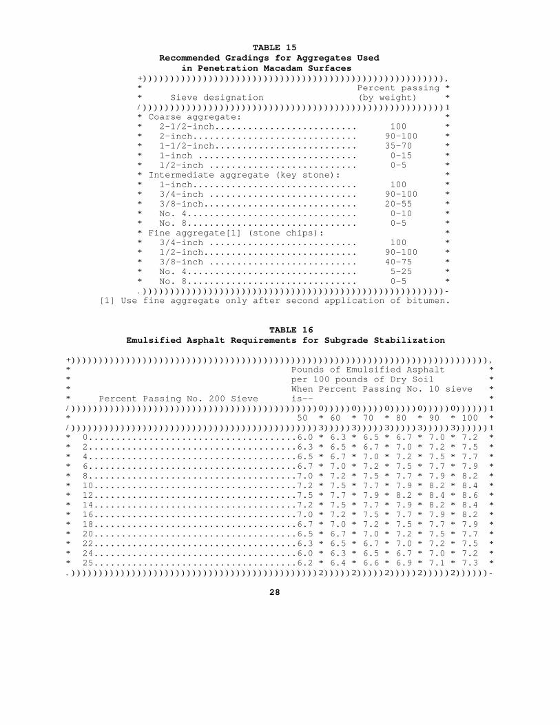
TABLE 15 Recommended Gradings for Aggregates Used in Penetration Macadam Surfaces +))))))))))))))))))))))))))))))))))))))))))))))))))))))), * Percent passing * * Sieve designation (by weight) * /)))))))))))))))))))))))))))))))))))))))))))))))))))))))1 * Coarse aggregate: * * 2-1/2-inch.......................... 100 * * 2-inch.............................. 90-100 * * 1-1/2-inch.......................... 35-70 * * 1-inch ............................. 0-15 * * 1/2-inch ........................... 0-5 * * Intermediate aggregate (key stone): * * 1-inch.............................. 100 * * 3/4-inch ........................... 90-100 * * 3/8-inch............................ 20-55 * * No. 4............................... 0-10 * * No. 8............................... 0-5 * * Fine aggregate[1] (stone chips): * * 3/4-inch ........................... 100 * * 1/2-inch............................ 90-100 * * 3/8-inch ........................... 40-75 * * No. 4............................... 5-25 * * No. 8............................... 0-5 * .)))))))))))))))))))))))))))))))))))))))))))))))))))))))- [1] Use fine aggregate only after second application of bitumen.
TABLE 16 Emulsified Asphalt Requirements for Subgrade Stabilization
+)))))))))))))))))))))))))))))))))))))))))))))))))))))))))))))))))))))))))))),* Pounds of Emulsified Asphalt ** per 100 pounds of Dry Soil ** When Percent Passing No. 10 sieve ** Percent Passing No. 200 Sieve is-- */)))))))))))))))))))))))))))))))))))))))))))))0)))))0)))))0)))))0)))))0))))))1* 50 * 60 * 70 * 80 * 90 * 100 */)))))))))))))))))))))))))))))))))))))))))))))3)))))3)))))3)))))3)))))3))))))1* 0......................................6.0 * 6.3 * 6.5 * 6.7 * 7.0 * 7.2 ** 2......................................6.3 * 6.5 * 6.7 * 7.0 * 7.2 * 7.5 ** 4......................................6.5 * 6.7 * 7.0 * 7.2 * 7.5 * 7.7 ** 6......................................6.7 * 7.0 * 7.2 * 7.5 * 7.7 * 7.9 ** 8......................................7.0 * 7.2 * 7.5 * 7.7 * 7.9 * 8.2 ** 10.....................................7.2 * 7.5 * 7.7 * 7.9 * 8.2 * 8.4 ** 12.....................................7.5 * 7.7 * 7.9 * 8.2 * 8.4 * 8.6 ** 14.....................................7.2 * 7.5 * 7.7 * 7.9 * 8.2 * 8.4 ** 16.....................................7.0 * 7.2 * 7.5 * 7.7 * 7.9 * 8.2 ** 18.....................................6.7 * 7.0 * 7.2 * 7.5 * 7.7 * 7.9 ** 20.....................................6.5 * 6.7 * 7.0 * 7.2 * 7.5 * 7.7 ** 22.....................................6.3 * 6.5 * 6.7 * 7.0 * 7.2 * 7.5 ** 24.....................................6.0 * 6.3 * 6.5 * 6.7 * 7.0 * 7.2 ** 25.....................................6.2 * 6.4 * 6.6 * 6.9 * 7.1 * 7.3 *.)))))))))))))))))))))))))))))))))))))))))))))2)))))2)))))2)))))2)))))2))))))-
28
(2) Stabilization With Liquid Asphalt. For an estimate of liquid asphaltrequirements, use the following expression: where:
p = .02(a) + .07(b) + .15(c) + .02(d) p = percent of residual asphalt by weight of dry aggregate. a = percent of aggregate retained on No. 50 sieve. b = percent of aggregate passing No. 50 and retained on No. 100 sieve. c = percent of aggregate passing No. 100 and retained on No. 200 sieve. d = percent of aggregate passing No. 200 sieve.
Section 9. RIGID PAVEMENT DESIGN
1. BASIC FACTORS. Design criteria for rigid pavements are outlined below.
a. Load Bearing Capacity. Rigid pavements distribute superposed wheel loadsover effective areas much larger than tire contact areas, greatly reducingstress intensity on subgrade and eliminating the need for high quality bases.While bases normally are not required for structural reasons, they usually arerequired for other reasons.
b. Bending Stresses and Curvature. Assume subgrade reaction or support atevery point proportional to vertical deflection of the slab at the point andelastic pavement. Assume subgrade support is continuous with no areas whereslab has deflected away from the subgrade. (1) Analysis. Stress analysis utilizes a basic relationship betweenbending moment and radius of curvature at any point:
EI M = )))) r where: r = radius of curvature of the pavement, M = bending moment of the pavement, E = modulus of elasticity of the pavement, I = moment of inertia of the pavement.
(2) Maximum Stress. Maximum pavement stresses occur when wheel loads arenear joints and exterior edges of slabs.
c. Effects of Friction and Warping. Frictional forces between slab andsubgrade interfere with pavement expansion and contraction, often resulting inpavement cracking. Design properly spaced contraction joints to control crack-ing caused by contraction. Excessive expansion and blowups occur infrequentlybecause most pavements are laid in warm weather. However, expansive aggregatesor wide temperature variations can cause blowups. (1) Vertical Temperature Gradients. Vertical temperature gradients inslabs cause warping. If the top of a slab is cooler than the bottom, the slabtends to curl up at the edges because of tension in the top surface. Tensionis an additive to tensile stresses caused by external load applied to slabedges. (2) Stress Analysis. Analysis for warping stresses usually is not consi-dered in pavement design; use an adequate factor of safety instead.
d. Subgrade and Base Uniformity. The thickness design procedure assumes aconstant modulus of subgrade reaction. Local variations in subgrade moduluscause increased stresses with possible pavement overstressing and decreasedlife; therefore, provide a uniform subgrade. (1) Pavements. Pavements perform better where construction traffic canbe kept off the subgrade.
29
(2) Subgrade Modulus. Make plate bearing tests in each area ofsubstantially different soil types or determine probable differences insubgrade module from previously made tests for comparable subgrade conditions.The subgrade modulus design value can vary for different areas.
e. Drainage. Provide adequate surface drainage to prevent ponding of waterand adequate subsurface drainage to prevent loss of subgrade bearing capacity.See NAVFAC DM 5.3 for surface drainage and Sections 5 and 7 for subsurfaceand base drainage.
f. Frost. Use special design procedures in areas having freezingtemperatures and frost-susceptible subgrade soil. (See Paragraph 5, below.)
2. RIGID PAVEMENT STRESSES. Design criteria for specific stresses are givenbelow: a. Wheel Configuration, Total Load, and Tire Pressure. Stresses developedin rigid pavement depend on total load, wheel configuration and spacing, andtire pressure. (1) Maximum Stress. Maximum stress is primarily a function ofindividual wheel loads when axle spacing exceeds about 4-1/2 feet. (2) Pavement Stress. For a given wheel load, pavement stress increaseswith increasing tire pressure.
b. Modulus of Subgrade Reaction. Obtain subgrade modulus (K) for a plateloading test. Make sufficient tests to obtain results for areas of differentsoil types. See Section 2. (1) Highway Design. Normally, large numbers of tests are not requiredfor highway design because of limited influence of subgrade modulus onrequired thickness of pavement. (2) Estimated Value. Estimated values of subgrade modulus are acceptableif adequate subsoil investigations have been made. For approximate values ofvarious soils, see Table 2. Do not use estimated values of subgrade modulusexceeding 300, unless substantiated by field-bearing test results. Values inexcess of 500 should not be used regardless of test results.
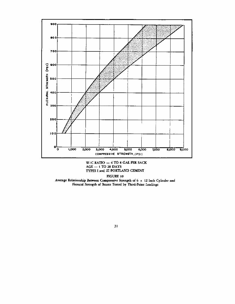
c. Flexural Strength of Concrete. Determine concrete flexural strength atfailure when tested at 28 days by third-point loading; use ASTM C78. Checkresults for probable reliability if compressive strengths are known fromaverage relationships of Figure 10. Do not use this figure in lieu of flexuralstrength tests. (1) Flexural Strength. For a typical plot of flexural strength variationwith age of concrete, see NAVFAC DM-21.
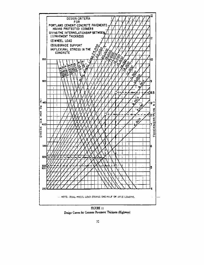
d. Thickness Design Procedure. Use design curves of Figure 11 with stressequal to concrete flexural strength divided by a factor of safety of 2.0, andwith subgrade modulus to obtain required thickness of slabs as shown by thedotted line. Thickness shall be rounded off to nearest 1/2 inch. Consider theneed for modifying computed slab thickness when unusual concrete behavioroccurs. Specific data for this modification are not available; obtainexperience of local highway departments. Conditions indicating modification ofcomputed thicknesses are: (1) Abnormally slow rate of increase in concrete strength. (2) Decrease of 28-day strength of concrete with time. (3) High moisture absorption by aggregate or concrete with resultingabnormal shrinkage. This can develop excessive curling or tensile stresses.
3. BASES. Provide bases under rigid pavements, primarily to maintain designload bearing capacity of pavement. In some cases, structural benefits from theuse of bases result in more economical construction. a. Uses. In addition to their structural functions, bases are used to: (1) Prevent "pump" of subgrade. (2) Provide uniform bearing surfaces for pavement slabs. (3) Replace soft, expansive, or highly compressible soils. (4) Replace frost-susceptible soils to protect subgrades from deterioration where subject to frost. 30
(5) Effect uniform movements in subgrade areas subject to frost heaving. (6) Provide operating surfaces for construction equipment, especiallyduring unfavorable weather.
b. Materials. Processed or stabilized, well-graded materials that are notfrost susceptible usually are suitable base materials under concretepavements; see Section 6. The plasticity index shall not exceed 5.
c. Compaction. Bases shall be constructed in layers. Design layers withmaximum compacted thicknesses of 6 inches and minimum compacted densities of95 percent of modified Proctor maximum density.
4. DRAINAGE. Provide surface drainage for water collection and removal fromroad surfaces, and for interception and collection of water flowing from adja-cent areas. Provide subsurface drainage to intercept, collect, and remove ground water flow: (a) into subgrade, (b) to lower high water tables, (c) todrain perched water tables, and (d) to prevent frost action. For design criteria for surface drainage, see NAVFAC DM-5.3. For subsurface drainage, seesubgrades in Section 4 and bases in Section 6.
5. DESIGN FOR FROST EFFECTS. In areas having freezing temperatures, determinethe need for designing for frost effects from state, county, or city highwayor street departments. Also, determine depths of frost penetration from high-way departments and from local utilities. Where design for frost is necessary,use results of local experiences. For more complete discussion of frostdesign, see NAVFAC DM-21.
6. JOINTS. Use expansion and contraction and construction joints in pavementsto prevent uncontrolled cracking caused by shrinkage and by contraction andexpansion induced by temperature changes. Also provide joints to controlrandom cracking results from uneven subgrade support and construction joints,as required. Use the kinds of joints and sealing compounds specified inJoints, Reinforcement, and Mooring Eyes Concrete Pavement, NAVFAC TS-02614.
7. DESIGN OF DISTRIBUTED REINFORCING STEEL. Distributed reinforcing steel (wire mesh and bar mat) is used to control cracking and to prevent cracks fromenlarging. Provide in accordance with NAVFAC TS-02614.
Section 10. DESIGN OF PORTLAND CEMENT CONCRETE
1. MIX DESIGN. Concrete mixes for rigid pavements should be designed in accor-dance with Portland Cement Concrete Pavement for Roads and Airfields. NAVFACTS-02613.
2. AIR ENTRAINMENT. Use air entraining admixture wherever available. Airentrainment usually causes moderate flexural strength decreases; consider thiswhen selecting design flexural strength.
3. LOW ALKALI CEMENT. As a precaution against alkali aggregate reactions, uselow alkali cement containing not more than 0.6 percent total alkalies.
Section 11. LOW-COST ROADS
1. BASIC FACTORS. Low-cost roads are suitable for low traffic volumes only andresult in excessive maintenance costs and unsatisfactory service if used improperly. Where roads are upgraded in stages, plan the work in phases thatwill permit existing roads to be incorporated in upgraded phases with aminimum loss of existing construction.
a. Progressive Improvement of Roads. Stage construction of roads can beaccomplished readily where a flexible type of construction is suitable andeconomical, as for normal pavement areas.
33
b. Stage Construction Steps. Construction steps are as follows: (1) Untreated aggregate surface. (2) Oil surface treatment. (3) Single or double bituminous surface treatments. (4) Mixed-in-place bituminous surfacings. (5) Plant-mixed bituminous surfacings.
2. TYPES OF LOW-COST PAVEMENTS. Classification of low-cost pavements are:
(1) Oil and soil-cement treatments. (2) Soil-lime. (3) Untreated surfacings (sand-clay, shell, soft limestone, clay gravel). (4) Single and double bituminous surface treatments. (5) Road-mixed or mixed-in-place bituminous surfacings. (6) Plant-mixed bituminous surfacings. (7) Penetration macadam. (8) Asphaltic concrete.
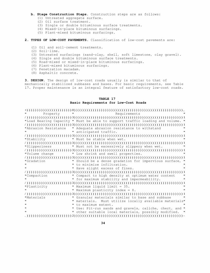
3. DESIGN. The design of low-cost roads usually is similar to that ofmechanically stabilized subbases and bases. For basic requirements, see Table17. Proper maintenance is an integral feature of satisfactory low-cost roads.
TABLE 17 Basic Requirements for Low-Cost Roads
+))))))))))))))))))))))0))))))))))))))))))))))))))))))))))))))))))))))))))))),* Property * Requirements */))))))))))))))))))))))3)))))))))))))))))))))))))))))))))))))))))))))))))))))1*Load Bearing Capacity * Must be able to support traffic loading and volume. */))))))))))))))))))))))3)))))))))))))))))))))))))))))))))))))))))))))))))))))1*Abrasion Resistance * Adequate abrasion resistance to withstand ** * anticipated traffic. */))))))))))))))))))))))3)))))))))))))))))))))))))))))))))))))))))))))))))))))1*Stability * Must be stable when wet. */))))))))))))))))))))))3)))))))))))))))))))))))))))))))))))))))))))))))))))))1*Slipperiness * Must not be excessively slippery when wet. */))))))))))))))))))))))3)))))))))))))))))))))))))))))))))))))))))))))))))))))1*Volume change * Low shrink and swell properties. */))))))))))))))))))))))3)))))))))))))))))))))))))))))))))))))))))))))))))))))1*Gradation * Should be a dense gradation for impervious surface, ** * to minimize infiltration. ** * Have slight excess of fines. */))))))))))))))))))))))3)))))))))))))))))))))))))))))))))))))))))))))))))))))1*Compaction * Compact to high density at optimum water content ** * for maximum stability and impermeability. */))))))))))))))))))))))3)))))))))))))))))))))))))))))))))))))))))))))))))))))1*Plasticity * Maximum liquid limit = 35. ** * Maximum plasticity index = 8. */))))))))))))))))))))))3)))))))))))))))))))))))))))))))))))))))))))))))))))))1*Materials * Granular materials similar to base and subbase ** * materials. Must utilize locally available materials** * to maximum extent. ** * Use: Pit-run sands and gravels, caliche, chert, and ** * other suitable local materials, possibly modified. *.))))))))))))))))))))))2)))))))))))))))))))))))))))))))))))))))))))))))))))))-
34
SECTION 12. SIDEWALKS
1. OVERALL REQUIREMENTS. Sidewalks should be designed to provide aneconomical, all-weather surface suitable for pedestrian traffic. See NAVFACDM-5.5 for widths and grades.
2. DESIGN. Use one of the sidewalk types discussed below, as appropriate forlocal conditions. Where sidewalks cross driveways and private entrances,design portions of sidewalks to be used by vehicular traffic for anticipatedloads.
a. Aggregate Base and Bituminous Surface. Use a stabilized base about 4inches thick, consisting of gravel, slag, stone, or other approved materials;and a minimum l-inch-thick surface course consisting of a bituminous sand-mixor a bituminous concrete-mix.
b. Concrete Walks. Use 2500-psi concrete, minimum 4 inches thick, groovedlongitudinally and transversely at 3- to 5-foot intervals to a depth of atleast 1/4 inch per inch of slab thickness, to provide weakened plane joints. (1) Use expansion joints to separate walks from buildings or structures. (2) Provide a wood float or broom finish with tooled edges at sides andtransverse joints.
c. Temporary Walks. Use stabilized soil mixtures that will be stable duringadverse weather conditions (see low-cost roads, Section 11). Utilize availablematerials, mixing with other materials for stabilization as necessary. Usebituminous surface treatment where justified, or stabilize soil in-place whereit is suitable, without any additional surfacing.
35
Section 13. UTILIZATION OF REINFORCING FABRICS IN ASPHALT PAVEMENT
1. FUNCTIONS. Reinforcing fabric may be used in asphalt pavement to serve two functions: a) interlayer between base course and subgrade to not only provide some reinforcement, but also to prevent intrusion of subgrade fines into granular base layers and to provide planar flow of water between base and subgrade, and b) tensile reinforcement of a thin asphalt overlay. Fabrics may be used to retard or minimize reflection cracking in asphalt resurfacings. Asphalt and portland cement concrete pavements of all types are frequently overlayed with additional layers of asphalt concrete to strengthen pavement that has been weakened due to fatigue cracking or environmentally induced cracking. Limited experience and test data indicate that fabrics can function to enhance the service life of asphalt pavement overlays.
2. FABRIC MATERIALS
a. Description. Fabrics available for use in pavement construction are made of synthetic fibers. The synthetic fiber fabrics are made with uniformity in production. Some are and some are not resistant to rot and mildew. The pore sizes in the fabrics are reasonably uniform. Fabric strength and resistance to chemicals vary from fabric to fabric. Available fabrics are either one of two types, woven or nonwoven. The woven fabrics are manufactured using the weaving process whereas the nonwoven fabrics are formed by bonding fibers together using heat fusion, chemical fusion or needle punching. The types of fibers used include polyester, polypropylene, polyethylene, polyamides, nylon or glass.
Representative types and styles of fabrics are summarized in Table 18. This list was prepared using information provided by fabric manufacturers and not all data is available for every brand and type of fabric.
b. Fabric Properties. The important fabric properties that affect pavement performance are described as follows:
(1) Grab Tensile Strength. The tensile strength of the fabric is important when the fabric serves as a reinforcement. As a pavement system deforms elastically, the fabric also deforms, thereby inducing tensile stresses in the fabric. The fabric must have sufficient tensile strength to resist these stresses.
(2) Trapezoidal Tear Strength. Once a hole or tear has been introduced into a fabric, the resistance of the fabric to the spreading of the damage is its tear resistance.
(3) Puncture Resistance. A fabric located between a granular material and the subgrade is subject to puncture by the granular material during the placement of the aggregate. The ability of the fabric to resist penetration is its puncture resistance.
(4) Burst Strength. The ability to resist stresses applied uniformly over a large area and in all directions is the burst strength of the fabric. This is a special case of the tensile type of failure.
Change 1, September 1985 36
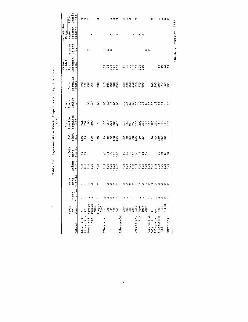
37
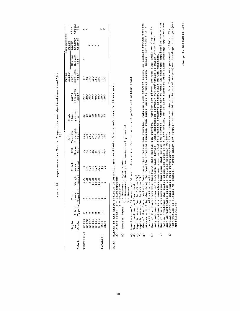
38
(5) Grab Elongation. Elongation may be due to the reorientation of the fibers in a fabric when stressed or due to the stretching of the fibers. Increased elongation reduces the amount of stress in the fabric and thereby the effectiveness of the fabric as a reinforcement.
(6) Asphalt Retention. The characteristic of paving fabric that measures the ability to retain and hold asphalt while in place. The normal units on this measure is weight/unit area.
(7) Equivalent Opening Size. The openings in a fabric noted in standard sieve sizes which are commonly used to refer to soil particle sizes.
(8) Modulus of Elasticity. The rate of increase of stress with respect to strain below the proportional limits. The modulus of elasticity is thus equal to the slope of the initial straight line portion of a stress-strain diagram.
(9) Coefficient of Water Permeability. A measure of the flow of water through a permeable media. This coefficient has units of velocity, e.g.cm/sec.
Test procedures for evaluating the above properties are summarized in Table 19.
3. CRITERIA FOR USE OF FABRICS
a. General. To achieve reinforcement from the use of fabrics in asphaltpavement, their range of application must not be overextended. Fabrics havebeen used successfully in many applications but, likewise, have failed toimprove pavement performance in many of the same situations. Experience hasshown, although no long-term performance data is yet available, that some ofthe fabrics do enhance the life of thin asphaltic resurfacings. When usedwith asphalt overlays of 3 inches (75mm) or less, reduced reflection crackingcan be achieved. The fabric not only retards or reduces reflection crackingbut prevents surface infiltration of water. Fabrics have shown goodperformance when used on pavements with fatigue cracking (alligator skinpattern), longitudinal construction joint cracks in asphalt pavement, and thelongitudinal joint between portland cement concrete pavement widened withflexible pavement. In general, fabrics have not proven to serve as well oncracks that are greater than 1/4 inch (6.25mm) wide. In these cases, thefabrics have not prevented a significant amount of reflection cracking butare believed to protect the pavement from surface water intrusion.
b. Overlay Thickness. Overlay thickness design should be accomplishedusing approved methods. Fabrics should not be used with overlays thicker than3 inches (75mm). Performance to date has not verified any economic advantagein thicker overlays. Likewise, fabrics
Change 1, September 1985 39
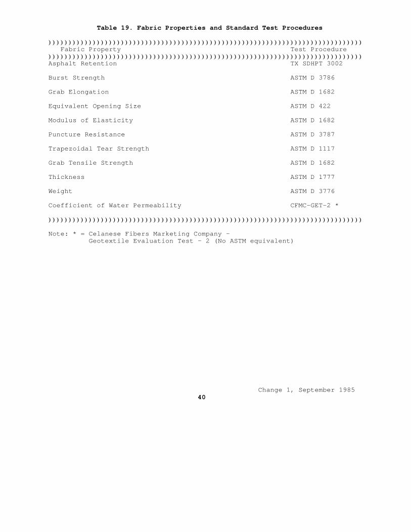
Table 19. Fabric Properties and Standard Test Procedures
)))))))))))))))))))))))))))))))))))))))))))))))))))))))))))))))))))))))))))))) Fabric Property Test Procedure))))))))))))))))))))))))))))))))))))))))))))))))))))))))))))))))))))))))))))))Asphalt Retention TX SDHPT 3002
Burst Strength ASTM D 3786
Grab Elongation ASTM D 1682
Equivalent Opening Size ASTM D 422
Modulus of Elasticity ASTM D 1682
Puncture Resistance ASTM D 3787
Trapezoidal Tear Strength ASTM D 1117
Grab Tensile Strength ASTM D 1682
Thickness ASTM D 1777
Weight ASTM D 3776
Coefficient of Water Permeability CFMC-GET-2 *
))))))))))))))))))))))))))))))))))))))))))))))))))))))))))))))))))))))))))))))
Note: * = Celanese Fibers Marketing Company - Geotextile Evaluation Test - 2 (No ASTM equivalent)
Change 1, September 1985 40
should not be used with overlays 1 inch (25mm) or thinner. If a levelingcourse is placed prior to the overlay, then the fabric should be between theleveling and overlay courses.
c. Tack Coat. The fabrics are bonded to the existing asphalt surface orthe surface of a leveling course by means of a tack coat of asphalt cement.
The selection of a tack coat should be a function of the temperature ofthe asphalt pavement surface at the time of construction. As with the tackcoat quantities, the type of tack coat is somewhat a variable with fabrictype. For most fabrics, asphalt cement grades from AC-5 (AR-2000) throughAC-20 (AR-8000) cover the range of applicability. When selecting a final tackcoat material and the temperature is known, the fabric manufacturer'srequirements should be consulted.
The amount of tack coat required is dependent on the condition andtexture of the asphaltic surface on which the fabric is to be placed and on the type of fabric. Most common fabrics require about 0.20 - 0.30 gal/sq. yd.of residual asphalt. Figure 12 relates surface texture to tack coat quantity.The designer may use the word description of the existing pavement surface orperform texture tests. The texture measure in Figure 12 is based on the puttyimpression test. The test equipment consists of 1) a 6-inch (150 mm)diameter by 1-inch (25mm) thick metal plate with a 4-inch (1OOmm) diameter,1/16-inch (1.56mm) deep recess machined into one side, and 2) a 15.90-gramball of silicone putty. When placed on a smooth surface, 15.90 grams ofputty will smooth out to a 4-inch (1OOmm) diameter circle, 1/16-inch(1.56mm) deep, thus completely filling the recess.
The silicone putty is formed into an approximate sphere and placed onthe pavement surface. The recess in the plate is centered over the putty, andthe plate is pressed down in firm contact with the road surface. The moreirregular the surface texture (the higher the macro-texture) the smaller theresulting putty diameter because more material is required to fill thesurface texture. Average texture depth, based on volume per unit area, iscalculated from an average of four diameter measurements.
d. Overlay Reinforcement. Fabrics that are suitable for use overdistressed asphalt pavement surfaces shall meet the specifications noted inTable 20. Generally, all the fabrics available and in use that meet thesespecifications are of the nonwoven type. Some products have had morewidespread use than others. The designer should check the data furnishedherein against any other manufacturers' literature, information or data thatmay be more current.
e. Layer Separation. Fabrics may be used as layer separators to preventcontamination of base materials in flexible pavements. Layer separation alsopermits expeditious construction in soft, yielding subgrades. Layerseparation may be a valuable treatment to consider in frost potential areas.The fabric will prevent the contamination of nonfrost susceptible materialsby minimizing subgrade intrusion into base
Change 1, September 1985 41
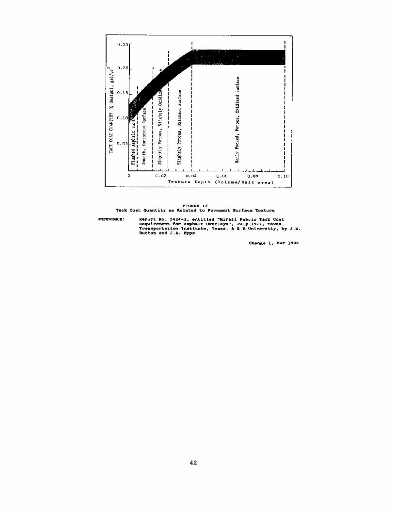
42
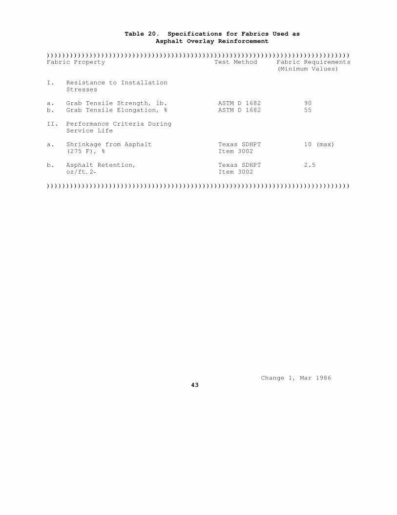
Table 20. Specifications for Fabrics Used as Asphalt Overlay Reinforcement
))))))))))))))))))))))))))))))))))))))))))))))))))))))))))))))))))))))))))))))Fabric Property Test Method Fabric Requirements (Minimum Values)
I. Resistance to Installation Stresses
a. Grab Tensile Strength, lb. ASTM D 1682 90b. Grab Tensile Elongation, % ASTM D 1682 55
II. Performance Criteria During Service Life
a. Shrinkage from Asphalt Texas SDHPT 10 (max) (275 F), % Item 3002
b. Asphalt Retention, Texas SDHPT 2.5 oz/ft.2- Item 3002
))))))))))))))))))))))))))))))))))))))))))))))))))))))))))))))))))))))))))))))
Change 1, Mar 1986 43
layers. The fabrics available and used for layer separation in flexible pavements are more numerous than those for overlay reinforcement. Thesefabrics should meet the requirements identified in Table 21. Generally theseare much stronger fabrics than those used in overlays and are of the wovenand nonwoven type. When considering the use of fabrics between layers thedesigner should refer also to local experience.
4. ECONOMICS OF FABRIC USE. Fabric uSe must not only be an engineeringimprovement, it must be a cost-effective improvement. The cost of fabric andits installation as a layer separator will vary with the type of fabric,experience of the contractor and size of the project. The cost of fabric hasbeen associated with the cost of an additional 1 (25mm) or 2 (50mm) inches ofbase layer thickness or about the same as lime treated subgrade. The designershould select thicknesses of layers as indicated in Section 7 FlexiblePavement Thickness design. Base or subbase thickness may be reduced by 2inches (50mm) when layer separation fabrics are specified but should not beless than minimum values set forth in Section 7. Furthermore, on subgradeswith a CBR less than 5 no reduction in base should be applied. In cases wheredesigns with fabric still cost more than conventional designs, such designsshould be recommended only when there is demonstrated experience of longerpavement life.
The use of fabric in conjunction with an asphalt overlay of an existingpavement must be a cost-effective application. There are no demonstrateddata that reliably indicate the relative load carrying value of fabric interms of asphalt overlay thickness. There is evidence that with the use offabrics over "alligator" or fatigued cracked asphalt pavement, reflectioncracking is minimized and longer pavement life can be expected. The type ofconsiderations that might warrant the extra expenditure for fabrics inasphalt overlays include: 1) areas with vertical clearance problems, and 2)high traffic areas which are difficult to close for repairs and/orrehabilitation.
Change 1, September 1985 44
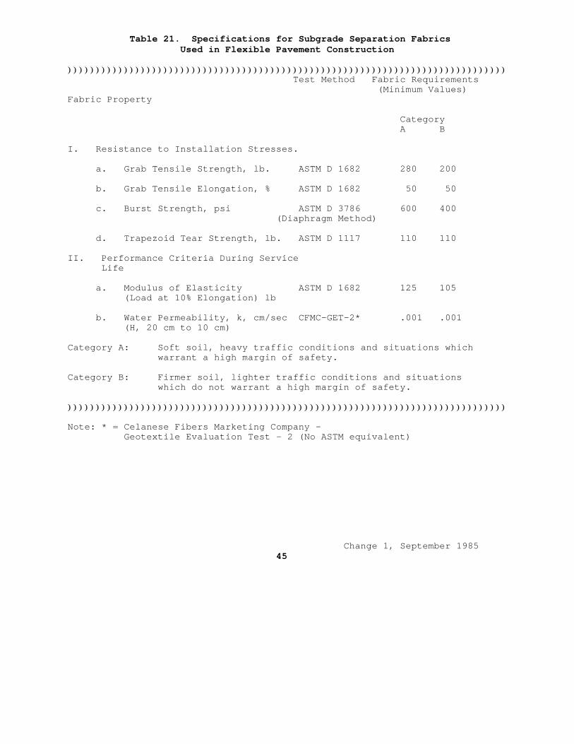
Table 21. Specifications for Subgrade Separation Fabrics Used in Flexible Pavement Construction
)))))))))))))))))))))))))))))))))))))))))))))))))))))))))))))))))))))))))))))) Test Method Fabric Requirements (Minimum Values)Fabric Property
Category A B
I. Resistance to Installation Stresses.
a. Grab Tensile Strength, lb. ASTM D 1682 280 200
b. Grab Tensile Elongation, % ASTM D 1682 50 50
c. Burst Strength, psi ASTM D 3786 600 400 (Diaphragm Method)
d. Trapezoid Tear Strength, lb. ASTM D 1117 110 110
II. Performance Criteria During Service Life
a. Modulus of Elasticity ASTM D 1682 125 105 (Load at 10% Elongation) lb
b. Water Permeability, k, cm/sec CFMC-GET-2* .001 .001 (H, 20 cm to 10 cm)
Category A: Soft soil, heavy traffic conditions and situations which warrant a high margin of safety.
Category B: Firmer soil, lighter traffic conditions and situations which do not warrant a high margin of safety.
))))))))))))))))))))))))))))))))))))))))))))))))))))))))))))))))))))))))))))))
Note: * = Celanese Fibers Marketing Company - Geotextile Evaluation Test - 2 (No ASTM equivalent)
Change 1, September 1985 45
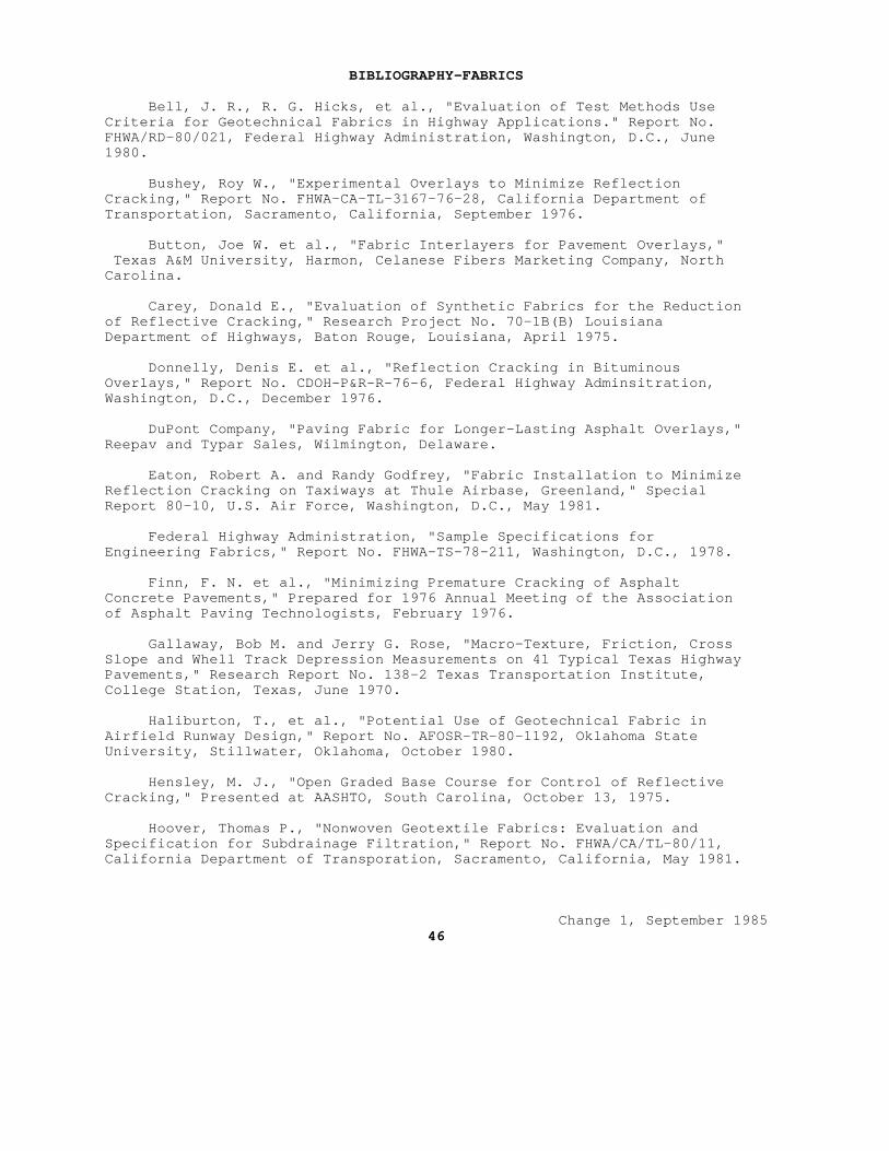
BIBLIOGRAPHY-FABRICS
Bell, J. R., R. G. Hicks, et al., "Evaluation of Test Methods Use Criteria for Geotechnical Fabrics in Highway Applications." Report No. FHWA/RD-80/021, Federal Highway Administration, Washington, D.C., June 1980.
Bushey, Roy W., "Experimental Overlays to Minimize Reflection Cracking," Report No. FHWA-CA-TL-3167-76-28, California Department of Transportation, Sacramento, California, September 1976.
Button, Joe W. et al., "Fabric Interlayers for Pavement Overlays," Texas A&M University, Harmon, Celanese Fibers Marketing Company, North Carolina.
Carey, Donald E., "Evaluation of Synthetic Fabrics for the Reduction of Reflective Cracking," Research Project No. 70-1B(B) Louisiana Department of Highways, Baton Rouge, Louisiana, April 1975.
Donnelly, Denis E. et al., "Reflection Cracking in Bituminous Overlays," Report No. CDOH-P&R-R-76-6, Federal Highway Adminsitration, Washington, D.C., December 1976.
DuPont Company, "Paving Fabric for Longer-Lasting Asphalt Overlays," Reepav and Typar Sales, Wilmington, Delaware.
Eaton, Robert A. and Randy Godfrey, "Fabric Installation to Minimize Reflection Cracking on Taxiways at Thule Airbase, Greenland," Special Report 80-10, U.S. Air Force, Washington, D.C., May 1981.
Federal Highway Administration, "Sample Specifications forEngineering Fabrics," Report No. FHWA-TS-78-211, Washington, D.C., 1978.
Finn, F. N. et al., "Minimizing Premature Cracking of Asphalt Concrete Pavements," Prepared for 1976 Annual Meeting of the Association of Asphalt Paving Technologists, February 1976.
Gallaway, Bob M. and Jerry G. Rose, "Macro-Texture, Friction, Cross Slope and Whell Track Depression Measurements on 41 Typical Texas Highway Pavements," Research Report No. 138-2 Texas Transportation Institute, College Station, Texas, June 1970.
Haliburton, T., et al., "Potential Use of Geotechnical Fabric in Airfield Runway Design," Report No. AFOSR-TR-80-1192, Oklahoma State University, Stillwater, Oklahoma, October 1980.
Hensley, M. J., "Open Graded Base Course for Control of Reflective Cracking," Presented at AASHTO, South Carolina, October 13, 1975.
Hoover, Thomas P., "Nonwoven Geotextile Fabrics: Evaluation and Specification for Subdrainage Filtration," Report No. FHWA/CA/TL-80/11, California Department of Transporation, Sacramento, California, May 1981.
Change 1, September 1985 46
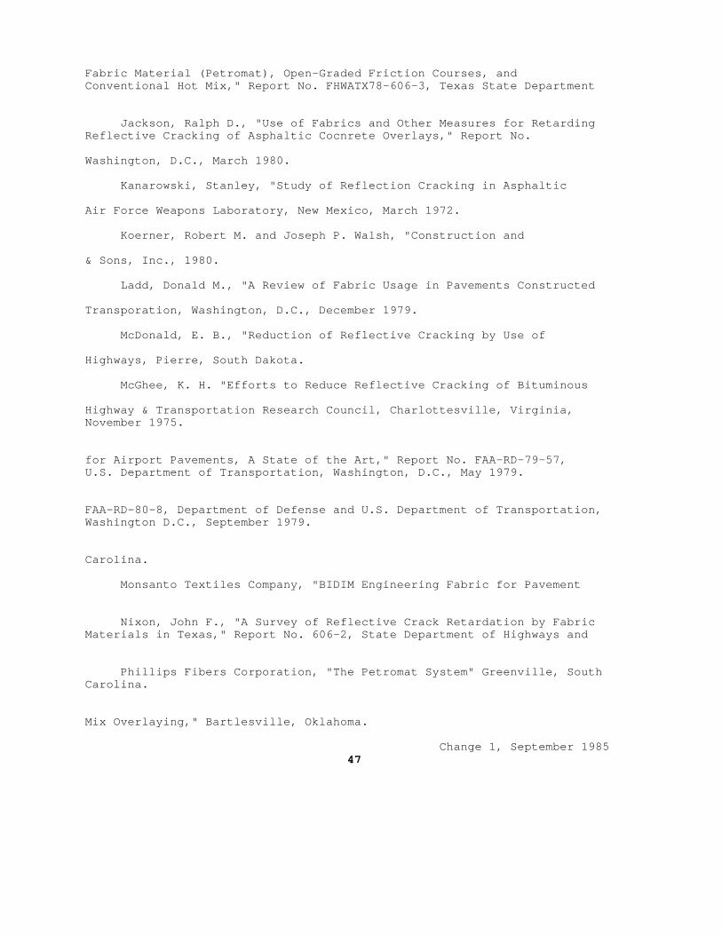
Fabric Material (Petromat), Open-Graded Friction Courses, and Conventional Hot Mix," Report No. FHWATX78-606-3, Texas State Department
Jackson, Ralph D., "Use of Fabrics and Other Measures for Retarding Reflective Cracking of Asphaltic Cocnrete Overlays," Report No.
Washington, D.C., March 1980.
Kanarowski, Stanley, "Study of Reflection Cracking in Asphaltic
Air Force Weapons Laboratory, New Mexico, March 1972.
Koerner, Robert M. and Joseph P. Walsh, "Construction and
& Sons, Inc., 1980.
Ladd, Donald M., "A Review of Fabric Usage in Pavements Constructed
Transporation, Washington, D.C., December 1979.
McDonald, E. B., "Reduction of Reflective Cracking by Use of
Highways, Pierre, South Dakota.
McGhee, K. H. "Efforts to Reduce Reflective Cracking of Bituminous
Highway & Transportation Research Council, Charlottesville, Virginia, November 1975.
for Airport Pavements, A State of the Art," Report No. FAA-RD-79-57, U.S. Department of Transportation, Washington, D.C., May 1979.
FAA-RD-80-8, Department of Defense and U.S. Department of Transportation, Washington D.C., September 1979.
Carolina.
Monsanto Textiles Company, "BIDIM Engineering Fabric for Pavement
Nixon, John F., "A Survey of Reflective Crack Retardation by Fabric Materials in Texas," Report No. 606-2, State Department of Highways and
Phillips Fibers Corporation, "The Petromat System" Greenville, South Carolina.
Mix Overlaying," Bartlesville, Oklahoma.
Change 1, September 1985 47
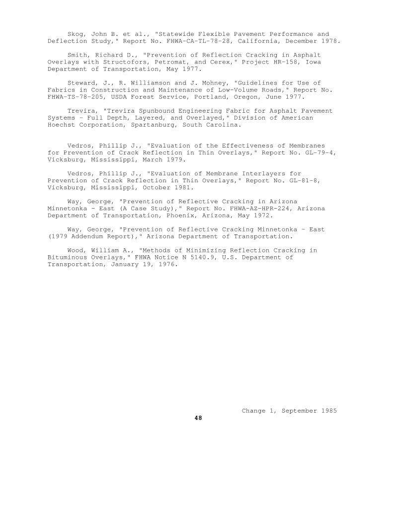
Skog, John B. et al., "Statewide Flexible Pavement Performance and Deflection Study," Report No. FHWA-CA-TL-78-28, California, December 1978.
Smith, Richard D., "Prevention of Reflection Cracking in Asphalt Overlays with Structofors, Petromat, and Cerex," Project HR-158, Iowa Department of Transportation, May 1977.
Steward, J., R. Williamson and J. Mohney, "Guidelines for Use of Fabrics in Construction and Maintenance of Low-Volume Roads," Report No. FHWA-TS-78-205, USDA Forest Service, Portland, Oregon, June 1977.
Trevira, "Trevira Spunbound Engineering Fabric for Asphalt Pavement Systems - Full Depth, Layered, and Overlayed," Division of American Hoechst Corporation, Spartanburg, South Carolina.
Vedros, Phillip J., "Evaluation of the Effectiveness of Membranes for Prevention of Crack Reflection in Thin Overlays," Report No. GL-79-4, Vicksburg, Mississippi, March 1979.
Vedros, Phillip J., "Evaluation of Membrane Interlayers for Prevention of Crack Reflection in Thin Overlays," Report No. GL-81-8, Vicksburg, Mississippi, October 1981.
Way, George, "Prevention of Reflective Cracking in Arizona Minnetonka - East (A Case Study)," Report No. FHWA-AZ-HPR-224, Arizona Department of Transportation, Phoenix, Arizona, May 1972.
Way, George, "Prevention of Reflective Cracking Minnetonka - East (1979 Addendum Report)," Arizona Department of Transportation.
Wood, William A., "Methods of Minimizing Reflection Cracking in Bituminous Overlays," FHWA Notice N 5140.9, U.S. Department of Transportation, January 19, 1976.
Change 1, September 1985 48
REFERENCES
1. AASHTO Interim Guide for Design of Permanent Structures, GDPS 2-72, Chapter III Revised, 1981; American Association of State Highway and Transportation Officials (formerly American Association of State Highway Officals), Suite 225, 444 N. Capitol St., N.W., Washington, D.C. 20001.
2. Airfield Pavements; NAVFAC DM-21, June 1973 (Reprinted with Change 1, June 1976 incorporated); U.S. Naval Publications and Forms Center, 5801 Tabor Ave., Philadelphia, PA 19120.
3. Asphalt Binder & Wearing Courses for Flexible Pavement (Central Plant Hot Mix), NAVFAC TS-02681, August 1980; U.S. Naval Publications and Forms Center, 5801 Tabor Ave., Philadelphia, PA 19120.
4. Bituminous Pavements Standard Practice, TM 5-822-8, June 1972; Department of the Army, Corps of Engineers, U.S. Army Engineer Waterways Experiment Station; P.O. Box 631, Vicksburg, MS 39180.
5. Bituminous Surface Treatment, NAVFAC TS-02677, August 1980, U.S. Naval Publications and Forms Center, 5801 Tabor Ave., Philadelphia, PA 19120.
6. Density of Soil in Place by the Sand-Cone Method, Test Method for, ASTM D 1556-82, American Society for Testing and Materials, 1916 Race St., Philadelphia, PA 19103.
7. Civil Engineering-Drainage Systems, NAVFAC DM-5.03, June 1979 (Change 1, December 1980); U.S. Naval Publications and Forms Center, 5801 Tabor Ave., Philadelphia, PA 19120.
8. Flexible Pavements for Roads, Streets, Walks, and Open Storage Areas, TM 5-822-5, May 1980; Department of the Army, Corps of Engineers, U.S. Army Engineer Waterways Experiment Station; P.O. Box 631, Vicksburg, MS 39180.
9. Flexural Strength of Concrete (Using Simple Beam with Third-Point Loading), Test Method for, ASTM C 78-84, American Society for Testing and Materials, 1916 Race St., Philadelphia, PA 19103.
10. General Provisions and Geometric Design for Roads, Streets, Walks, and Open Storage Areas, NAVFAC DM-5.05, April 1977; U.S. Naval Publications and Forms Center, 5801 Tabor Ave., Philadelphia, PA 19120.
11. Graded Aggregate Base Course for Flexible Pavement, NAVFAC TS-02686, October 1980; U.S. Naval Publications and Forms Center, 5801 Tabor Ave., Philadelphia, PA 19120.
12. Civil Engineering-Hydrology and Hydraulics, NAVFAC DM-5.02, June 1979; U.S Naval Publications and Forms Center, 5801 Tabor Ave., Philadelphia, PA 19120.
NAVFAC DM-5.4 Change 1, September 1985 49
TS-02614, January 1979; U.S. Naval Publications and Forms Center, 5801 Tabor Ave., Philadelphia, PA 19120.
Embankments, and Foundations, MIL-STD (Military Standard) 619B, June 1968; U.S. Naval Publications and Forms Center, 5801 Tabor Ave.,
15. Test Methods for Bituminous Paving Materials, MIL-STD (Military Standard) 620A, January 1966, with Notice 1, May 1967; U.S. Naval
19120.
16. Subgrade, Subbase, and Test Method for Pavement Base-Course
Notice 2, December 1968; U.S. Naval Publications and Forms Center, 5801 Tabor Ave., Philadelphia, PA 19120.
Publication MS-2-84; The Asphalt Institute, The Asphalt Institute Building, College Park, MD 20740.
Using 5.5 lb (2.49-Kg) Rammer and 12-Inch (305-mm) Drop, Test Methods for, ASTM D 698-78; American Society for Testing and
19. Moisture-Density Relations of Soils and Soil-Aggregate Mixtures Using 10-lb (4.54-Kg) Rammer and 18-Inch (457-mm) Drop, Test Methods
1916 Race St., Philadelphia, PA 19103.
20. Nonrepetitive Static Plant Load Tests of Soils and Flexible Pavement
Pavements, Method for, ASTM D 1196-64 (R 1977), American Society for Testing and Materials, 1916 Race St., Philadelphia, PA 19103.
NFGS-02559 (October 1983); U.S. Naval Publications and Forms Center, 5801 Tabor Ave., Philadelphia, PA 19120.
Structures, NAVFAC DM-7.02, May 1982; Soil Dynamics, Deep Stabilization, and Special Geotechnical Construction, NAVFAC
Tabor Ave., Philadelphia, PA 19120.
23. Transportation Materials and Methods for Sampling and Testing,
(AASHTO) HM-13 PT 1-82; Suite 225, 444 N. Capitol St., N.W. Washington, D.C. 20001.
50

24. Structural Engineering: General Requirements, NAVFAC DM-2.01, May 1980; Loads, NAVFAC DM-2.02, November 1981; Steel Structures, NAVFAC DM-2.03, May 1980; Concrete Structures, NAVFAC DM-2.04, May 1980; Timber Structures, NAVFAC DM-2.05, May 1980; Aluminum Structures, Masonry Structures, Composite Structures, Other Structural Materials, NAVFAC DM-2.06, May 1980; U.S. Naval Publications and Forms Center, 5801 Tabor Ave., Philadelphia, PA 19120.
NAVFAC DM-5.4 Change 1, September 1985 51