NAVAL POSTGRADUATE SCHOOL Monterey, … SECURITY CLASSIFICATION OF THIS PAGE REPORT DOCUMENTATION...
160
NAVAL POSTGRADUATE SCHOOL Monterey, California AD-A 2 4 6 820 DTIC S MAR 0 41992"t D THESIS INMARSAT COMMUNICATIONS SYSTEM: A SYSTEMS APPROACH by Aristides Ioannis Fasoulas June, 1991 Co-Advisor: Dan C. Boger Co-Advisor: William R. Gates Approved for public release; distribution is unlimited. 92-05286
Transcript of NAVAL POSTGRADUATE SCHOOL Monterey, … SECURITY CLASSIFICATION OF THIS PAGE REPORT DOCUMENTATION...
NAVAL POSTGRADUATE SCHOOLMonterey, California
AD-A 2 4 6 820
DTICS MAR 0 41992"t
D THESIS
INMARSAT COMMUNICATIONS SYSTEM:A SYSTEMS APPROACH
by
Aristides Ioannis Fasoulas
June, 1991
Co-Advisor: Dan C. Boger
Co-Advisor: William R. Gates
Approved for public release; distribution is unlimited.
92-05286
UNCLASSIFIED
SECURITY CLASSIFICATION OF THIS PAGE
Form ApprovedREPORT DOCUMENTATION PAGE 0MB No 0704-0188
la REPORT SECURITY CLASSIFICATION lb RESTRICTIVE MARKINGS
UNCLASSIFIED2a SECURITY CLASSIFICATION AUTHORITY 3 DISTRIBUTION/AVAILABILITY OF REPORT
2b DECLASSIFICATION/DOWNGRADING SCHEDULE Approved for public release;distribution is unlimited
4 PERFORMING ORGANIZATION REPORT NUMBER(S) 5. MONITORING ORGANIZATION REPORT NUMBER(S)
6a. NAME OF PERFORMING ORGANIZATION 6b OFFICE SYMBOL 7a. NAME OF MONITORING ORGANIZATION(If applicable)
Naval Pstgraduate School AS Naval Postgraduate School6c. ADDRESS (City, State, and ZIP Code) 7b ADDRESS (City, State, and ZIP Code)
Monterey, CA 93943-5000 Monterey, CA 93943-5000
8a. NAME OF FUNDING/SPONSORING 8b OFFICE SYMBOL 9 PROCUREMENT INSTRUMENT IDENTIFICATION NUMBERORGANIZATION (if applicable)
8c. ADDRESS (City, State, and ZIP Code) 10 SOURCE OF FUNDING NUMBERS
PROGRAM PROJECT TASK WORK UNITELEMENT NO NO NO ACCESSION NO
11 TITLE (Include Security Classification)
INMARSAT COMMUNICATIONS SYSTEM: A SYSTEMS APPROACH
12 PERSONAL AUTHOR(S)
FASOULAS, Aristedes13a TYPE OF REPORT 13b TIME COVERED 14. DATE OF REPORT (Year, Month, Day) 15 PAGE COUNT
Masters Thesis FROM TO 1991 June 16016 SUPPLEMENTARY NOTATION The views expressed in this thesis are those of theauthor and do not reflect the official policy or position of the Depart-ment of Defense of the US Government.17 COSATI CODES 18 SUBJECT TERMS (Continue on reverse if necessary and identify by block number)
FIELD GROUP SUB-GROUP Satellite communications; Internationalsatellite communications; INMARSAT; Satellitevulnerability
19 ABSTRACT (Continue on reverse if necessa y and identify by block number)
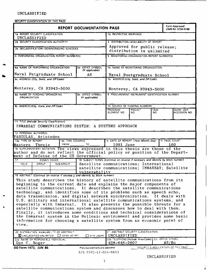
This study describes the history of satellite communications from itsbeginning to the current date and explains the major components ofsatellite communications. It describes the satellite communicationstechnology, and identifies some of its problems such as speech echo,data transmission, and digital network synchronization. It deals withU.S. military and international satellite communications systems, andespecially with Inmarsat. It also presents the possible threats for asatellite communications system and discusses how to deal with them.Finally, it introduces some conditions and technical considerations ofthe Inmarsat system in the Hellenic environment and provides some basicinformation for choosing a satellite system from an economic point ofview.
20 DISTRIBUTION AVAILABILITY OF ABSTRACT 21 ABSTRACT SECURITY CLASSIFICATION
MXUNCLASSIFIED'UNLIMITED 0 SAME AS R)T 0 DT!C USERS UNCLASSIFIED22a NAME OF RESPONSIBLE INDIVIDUAL 22b TELEPHONE (Include Area Code) 22c OFFICE SYMBO
Dan C. Boger 408-646-2607 1 AS/Bo
DD Form 1473, JUN 86 Previous editions are obsolete SECURITY CLASSFCAT_ _OFO_ T_,' PAGE
S/N 0102-LF-014-6603
UNCLASSIFIEDi

Approved for public release; distribution is unlimited.
Inmarsat Communications System:
A Systems Approach
by
Aristides I. FasoulasLieutenant Commander, Hellenic Navy
B.S., Hellenic Naval Academy, 1976
Submitted in partial fulfillment
of the requirements for the degree of
MASTER OF SCIENCE IN TELECOMMUNICATIONS SYSTEMS
MANAGEMENT
from the
NAVAL POSTGRADUATE SCHOOL
4 n1991
Author: ___
A ristides I. Fasoulas
Approved by: CDan C. Boger, T i s Co-Advisor
William Gates, Thesis Co-Advisor
DaidR. "hippl' Chairman
Department of Administ ie ceces

ABSTRACT
This study describes the history of satellite
communications from its beginning to the current date and
explains the major components of satellite communications. It
describes the satellite communications technology, and
identifies some of its problems such as speech echo, data
transmission, and digital network synchronization. It deals
with U.S military and international satellite communications
systems, and especially with Inmarsat. It also presents the
possible threats for a satellite communications system and
discusses how to deal with them. Finally, it introduces some
conditions and technical considerations of the Inmarsat system
in the Hellenic environment and provides some basic
information for choosing a satellite system from an economic
point of view. Ii., ________________ACC ;Sioli For
U , o ' Cyv C Q J
D. t__ :b.tic.'/.... . .. .. _
cop"
)I--l-ii
°,°Ior

TABLE OF CONTENTS
1. INTRODUCTION .................................................. 1
A. BACKGROUND ............................................ 1
B. O BJECTIVES .............................................. 1
C. ORGANIZATION .......................................... 2
II. DEVELOPMENT OF SATELLITE COMMUNICATIONS ................... 4
A. HISTORICAL BACKGROUND ................................ 4
B. SATELLITE COMMUNICATIONS TECHNOLOGY ................. 6
1. Basic Concepts of Satellite Communications Systems ............ 6
a. Satellite RF-Link .................................... 7
b. Communications Subsystem ........................... 8
(1) Communications Repeater ........................ 9
(2) Communications Antenna ....................... 12
c. Communications Satellite (spacecraft) .................. 14
(1) Spin Stabilization .............................. 17
(2) Three Axes Stabilization ......................... 17
d. Earth Station ............................... ..... 18
(1) Earth station antenna ........................... 18
(2) Receivers .................................... 21
(3) High power amplifier .......................... 23
iv

(4) Upconverter .. . . . . . . . . . . . . . . . . 24
(5) Primary power................................ 24
e. Terrestrial link................................... 25
2. Orbits .............................................. 26
a. General ......................................... 26
b. Foundation of the theory ............................ 27
C. Orbital perturbations ............................... 27
d. Geostationary orbit ................................ 28
(1) Slant range and Coverage angle ................... 29
(2) Advantages of Geostationary orbit .................. 31
(3) Disadvantages of geostationary orbit ................ 32
3. Multiple Access...................................... 32
a. General........................................ 32
b. Frequency-division multiple access..................... 33
(1) Advantages of FDMA........................... 34
(2) Disadvantages of FDMA......................... 34
C. Time-division multiple access......................... 35
(1) Advantages of TDMA........................... 36
(2) Disadvantages of TDMA ......................... 36
d. Code-division multiple access......................... 37
(1) Advantages of CDMA .......................... 38
(2) Disadvantages of CDMA ........................ 38
e. Comparison of multiple access techniques ................ 40
C. SPECIAL PROBLEMS IN SATELLITE COMMUNICATIONS .......... 41
V

1. Speech echo .......................................... 41
a. Echo suppression .................................. 41
b. Echo cancellation .................................. 42
2. Data transmission ..................................... 42
a. Protocols ........................................ 42
3. Digital network synchronization .......................... 44
D. RELIABILITY OF SATELLITE COMMUNICATIONS SYSTEMS ....... 44
1. G eneral ............................................. 44
2. Classes of failure ...................................... 45
3. Mean time between failures (MTBF) ....................... 46
4. Probability of survival or reliability ........................ 47
5. M ission Reliability ..................................... 48
a. Without spare satellite in orbit ........................ 48
b. With a back-up satellite (in orbit) ...................... 48
E. ADVANTAGES AND DISADVANTAGES OF SATELLITE
COMMUNICATIONS ...................................... 49
1. A dvantages .......................................... 50
2. Disadvantages ........................................ 50
Il. MILITARY SATELLITE COMMUNICATIONS ......................... 51
A. BACKGROUND ........................................... 51
B. DEVELOPMENT OF US MILITARY COMMUNICATION SATELLITE
PRO G RA M S .............................................. 51
1. IDCSP (Initial Defense Communication Satellite Program) ....... 53
vi
2. DSCS II (Defense Satellite Communication System, Phase II) ..... 54
3. D SC S III ............................................. 54
4. Tactical Satellites (TACSAT) .............................. 56
5. Fleet Satellite Communications (FLTSATCOM) ............... 57
6. LEASAT Satellite ...................................... 59
C. ADVANTAGES/DISADVANTAGES ........................... 60
1. A dvantages .......................................... 60
2. Disadvantages ........................................ 60
IV. INTERNATIONAL SATELLITE COMMUNICATIONS: INMARSAT ........ 61
A. INTRODUCTION .......................................... 61
1. Intelsat (International Telecommunication Satellite Consortium) .. 62
a. Intelsat-1 ........................................ 62
b . Intelsat-2 ........................................ 62
c. Intelsat-3 ........................................ 63
d. Intelsat-4 ...................... ................. 63
e. Intelsat-4A ....................................... 64
f. Intelsat-5 ........................................ 64
g. Intelsat-5A ....................................... 65
h. Intelsat-6 ........................................ 65
i. In telsat-7 ........................................ 66
2. Eutelsat (European Telecommunications Satellite Organization) ... 66
B. IN M A RSAT .............................................. 66
1 Background .......................................... 66
vii

a. The Establishment of INMARSAT ..................... 67
b. Purpose ......................................... 68
c. Organization ..................................... 68
2. Facts about INMARSAT ................................. 68
a. M aritime applications .............................. 69
b. Aircraft applications ................................ 69
c. Land applications .................................. 69
3. The satellite system .................................... 70
4. User term inals ........................................ 74
a. Standard-A terminal ................................ 74
(1) Above and Below Deck Equipment (ADE and BDE) ... 75
(2) Tracking and Stabilization ....................... 75
(3) SES's antennas ................................ 76
b. Standard-C terminal ................................ 76
(1) Two-way communications ....................... 78
(2) FleetNet & SafetyNet ........................... 78
5. Coast Earth Stations (CES) ............................... 78
a. A ntenna ......................................... 80
b. L-band functions .................................. 80
6. The Global Maritime Distress and Safety System (GMDSS) ...... 81
a. Background ...................................... 82
b. The new system ................................... 82
7. Aeronautical Satellite Communications ..................... 83
C. FUTURE DEVELOPMENTS OF INMARSAT SYSTEM .............. 84
viii

V. SATELLITE COMMUNICATIONS VULNERABILITY .................... 87
A. INTRODUCTION .......................................... 87
B. THREATS TO COMMUNICATION LINKS ...................... 88
1. U plink .............................................. 89
2. D ow nlink ............................................ 89
3. Throughlink .......................................... 90
4. Crosslink ............................................ 90
C. JAMMING SIGNALS ....................................... 90
1. Interception and Jamning ............................... 91
2. Jammer Description .................................... 91
3. Jamming of links using FDMA/PSK ....................... 93
4. Antijamming Techniques using spread spectrum .............. 94
5. Uplink-Downlink Jammer ............................... 96
a. Uplink Jam m er .................................... 96
b. Downlink Jammer ................................. 97
D. SUMMARY AND CONCLUSIONS ............................ 97
a. Frequency hopping vs Jamn ers ....................... 98
VI. CONDITIONS AND TECHNICAL CONSIDERATIONS OF INMARSAT SYSTEM
IN THE HELLENIC ENVIRONMENT ............................. 100
A. INTRODUCTION ......................................... 100
B. INMARSAT IN HELLENIC ENVIRONMENT ................... 100
1. Background ......................................... 100
2. Thermopylae's Coast Earth Station ........................ 101
ix

3. Services provided and Dialing procedures .................. 102
a. Services ........................................ 102
b. Dialing procedures ................................ 103
(1) Sending a telex to a ship from Greece ............. 103
(2) Making automatic calls from a ship ............... 103
(3) Sending a telex from a ship ..................... 104
(4) Making a call to a ship from Greece .............. 105
C. ECONOMICS OF SATELLITE BUSINESS SERVICES .............. 106
1. Background ......................................... 106
2. Economically Relevant Technical Properties of Satellites ....... 106
3. Charges for INMARSAT services in Greece ................. 107
D. TECHNICAL CONSIDERATIONS FOR INMARSAT IN THE HELLENIC
ENVIRONMENT ......................................... 117
1. Uplink and Downlink calculations ........................ 117
a. Uplink calculation (Frequency 6.42 GHz) ............... 119
b. Downlink calculation (Frequency 1.54 GHz) ............ 119
VII. CHOOSING A SATELLITE COMMUNICATIONS SYSTEM .............. 121
A. INTRODUCTION ......................................... 121
B. ECONOMICS OF A COMMUNICATION SYSTEM ............... 121
1. Economics of Scale .................................... 121
2. Market Demand and Supply ............................ 122
C. EVALUATING TELECOMMUNICATION SYSTEMS ........... 125
D. BASIC CONCEPTS OF COST-EFFECTIVENESS ANALYSIS ........ 126
x

1. Background 126
2. Cost Structure ....................................... 126
3. Life-cycle cost ....................................... 127
a. Research and Development cost (R&D) ................ 128
b. Investm ent cost .................................. 128
c. Operation and Support cost (O&S) .................... 128
d. Salvage cost ..................................... 128
E. COST-EFFECTIVENESS ANALYSIS ........................... 130
1. Satellite Cost M odel ................................... 131
a. Assumptions .................................... 131
b. Cost Structure ................................... 132
c. C ost Elem ents ................................... 132
(1) Investm ent Cost .............................. 133
(2) Operation and Support cost ..................... 135
VIII. CONCLUSION3 AND RECOMMENDATIONS ....................... 136
A . CO NCLUSION S .......................................... 136
B. RECOMMENDATIONS .................................... 137
LIST O F REFERENCES ............................................. 138
BIBLIO G RA PH Y .................................................. 140
INITIAL DISTRBUTION LIST .................... 143
xi
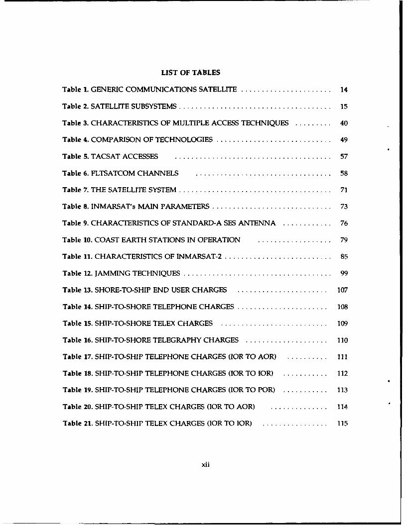
LIST OF TABLES
Table 1. GENERIC COMMUNICATIONS SATELLITE ...................... 14
Table 2. SATELLITE SUBSYSTEMS ..................................... 15
Table 3. CHARACTERISTICS OF MULTIPLE ACCESS TECHNIQUES ......... 40
Table 4. COMPARISON OF TECHNOLOGIES ............................ 49
Table S. TACSAT ACCESSES . ...................................... 57
Table 6. FLTSATCOM CHANNELS . ................................. 58
Table 7. THE SATELLITE SYSTEM ..................................... 71
Table 8. INMARSAT's MAIN PARAMETERS ............................. 73
Table 9. CHARACTERISTICS OF STANDARD-A SES ANTENNA ............ 76
Table 10. COAST EARTH STATIONS IN OPERATION ................... 79
Table 11. CHARACTERISTICS OF INMARSAT-2 .......................... 85
Table 12. JAMMING TECHNIQUES .................................... 99
Table 13. SHORE-TO-SHIP END USER CHARGES ...................... 107
Table 14. SHIP-TO-SHORE TELEPHONE CHARGES ...................... 108
Table 15. SHIP-TO-SHORE TELEX CHARGES .......................... 109
Table 16. SHIP-TO-SHORE TELEGRAPHY CHARGES .................... 110
Table 17. SHIP-TO-SHIP TELEPHONE CHARGES (IOR TO AOR) .......... .II
Table 18. SHIP-TO-SHIP TELEPHONE CHARGES (IOR TO IOR) ........... 112
Table 19. SHIP-TO-SHIP TELEPHONE CHARGES (IOR TO POR) ........... 113
Table 20. SHIP-TO-SHIP TELEX CHARGES (IOR TO AOR) .............. 114
Table 21. SHIP-TO-SHIP TELEX CHARGES (IOR TO IOR) ................ 115
xii

Table 22. SHIP-TO-SHIP TELEX CHARGES (IOR TO POR)................... 116
Table 23. SATELLITE COST ELEMENTS.................................134
xii

LIST OF FIGURES
Figure 1. Basic Satellite Links .......................................... 7
Figure 2. End-to-end Satellite Communications Link ......................... 9
Figure 3. Communications Repeater .................................... 10
Figure 4. Wideband communications receiver-downconverter ................. 11
Figure 5. Communications subsystem diagram ........................... 13
Figure 6. Spin-stabilized spacecraft ..................................... 16
Figure 7. Three axes stabilized spacecraft ................................ 16
Figure 8. Block diagram of an earth station ............................ 19
Figure 9. Paraboloid antenna ....................................... 21
Figure 10. Cassegrain antenna ............................... 21
Figure 11. Receiver chain .................................... 22
Figure 12. Upconverter, single conversion ................................ 24
Figure 13. Upconverter, dual conversion ................................ 24
Figure 14. Placement of a satellite in a geostationary orbit .............. 29
Figure 15. Coverage angle and Slant range .............................. 30
Figure 16. FDMA frame structure .................................... 34
Figure 17. TDMA network .......................................... 37
Figure 18. Principle of CDMA, Encoding ............................. 39
Figure 19. Principle of CDMA, Decoding ................................ 39
Figure 20. Basic classes of protocols .................................. 43
Figure 21. Interface between satellite system and terrestrial facilities ....... 44
xiv
Figure 22. Bathtub failure rate curve ................................... 46
Figure 23. INMARSAT's coverage area................................. 72
Figure 24. A Standard-A SES Antenna................................. 76
Figure 25. Coast Earth Station....................................... 81
Figure 26. INMARSAT-2............................................ 86
Figure 27. Jammer and Repeater Geometry ............................... 92
Figure 28. Sending a telex to a ship from Greece.......................... 103
Figure 29. Making automatic calls from a ship........................... 104
Figure 30. Sending a telex from a ship................................ 105
Figure 31. Economies-of-scale diagram ................................. 122
Figure 32. Demand and Supply...................................... 123
Figure 33. Change in the Quantity Demanded............................124
Figure 34. Change in the Quantity Supplied............................ 125
Figure 35. Life-Cycle Cost Structure................................. 129
Figure 36. Satellite Cost Structure................................... 133
xv

ACKNOWLEDGEMENTS
Completing this thesis, I would like to express my sincere appreciation and gratitude
to my advisors, Dr. Dan C. Boger and Dr William R. Gates, for their assistance and
guidance.
I dedicate this thesis to my wife, Kalitsia, and my two sons, John and Spyros, for
their great help, support, and encouragement during all this period, including late nights
and weekends that were spent in writing this thesis. Finally a special thanks is due to the
Hellenic Navy for giving me this special opportunity to study at the Naval Postgraduate
School.
xvi

I. INTRODUCTION
A. BACKGROUND
Recent years have witnessed dramatic changes in telecommunications. They are
nowhere more apparent than in the communications satellite sector. The rate of
development of satellite communications over the last 30 years has been swift and
spectacular. International communications volume has increased by a factor of almost one
hundred in three decades, mainly as a result of satellites. Nearly 150 satellites are in
geostationary orbit today. This number is expected to grow to 300 by the end of this
century. Approximately 170 countries use domestic satellite television, radio, telephone,
and/or data services. Costs have fallen, satellite lifetimes have expanded, and technological
innovations have come quickly.
B. OBJECTIVES
The underlying purpose of this thesis is to analyze the International Maritime
Satellite system (INMARSAT). Primary emphasis will be on determining if this
communications satellite system is effective, reliable, and survivable in a hostile
environment. Also, depending upon the advantages and disadvantages of such a system,
would it provide security and survivability in the Hellenic environment? Of particular
concern will be the system's ability to maintain an operational communication link in a
jamming stressed environment.

Cost considerations are always crucial to the development and success of
communications systems. While specific costs for the development and deployment of the
INMARSAT system will not be examined, key factors affecting those costs will be reviwed.
C. ORGANIZATION
This thesis is arranged into eight chapters, each having specific objectives as follows:
CHAPTER II provides the historical background to give the reader a quick insight
into the development of satellite communications through the last 30 years. Specifically,
it gives the general description of a satellite communications system and its subsystems.
It also includes information about satellite orbits, multiple access techniques, and focuses
on some special problems of satellite communications. Finally, it considers reliability, and
examines the advantages and disadvantages of these systems.
CHAPTER III provides the reader with a general overview of the United States
military satellite communications systems (unclassified part), and focuses on the
requirements such a system has to satisfy.
CHAPTER IV deals with International Satellite Communications systems, and
presents a general overview of the INTELSAT program. Primary interest is on the
technology applied to the INMARSAT system. This is discussed in more detail. It also
includes an economic analysis of the INMARSAT system from a subscriber's point of view.
CHAPTER V presents the possible threats for a satellite communications system and
discusses how to deal with them.
CHAPTER VI introduces some conditions and technical considerations of the
INMARSAT system in the Hellenic environment.
2

CHAPTER VII presents the basic information needed for choosing a satellite
communications system from an economic point of view.
CHAPTER VIII discusses the conclusions and findings of this study.
3

II. DEVELOPMENT OF SATELLITE COMMUNICATIONS
A. HISTORICAL BACKGROUND
The first operational communication satellite was the moon which was used as a
passive reflector by the U.S Navy in the late 1950s for low-data-rate communication
between Washington D.C and Hawaii. The first communication through an artificial
satellite occurred in October 1957 when the Soviet satellite Sputnik I transmitted telemetry
information for twenty-one days. This success was followed by a large space activity by
the United States, starting with Explorer I. This satellite was launched in January 1958 and
transmitted telemetry for nearly five months. The first artificial satellite used for voice
communications was Score, which was launched in December 1958 and used to transmit
President Eisenhower's Christmas message of that year.[Ref. 1:p. 11
During this first period in the history of satellite communications, some problems
and limitations arose, such as cargo size, launch vehicles, and the reliability of the
electronics used in space. To try to solve some of these problems, an experimental passive
repeater, ECHO I, was launched and placed in medium-altitude orbit in 1960. The
approach for this experiment was simple and credible (signals were reflected from the
metallic surface of this satellite), but large transmitters were needed on the ground to
transmit even very low rate data.[Ref. 2:p. 3]
Bell Systems planned and built Telstar I and II, which were active communication
satellites and were launched into a medium-altitude elliptical orbit by NASA in July 1962
and May 1963, respectively. Project Telstar is the best known of active communication
satellites, probably because it was the first to transmit television programs across the
4
Atlantic. The communication capacity of Telstar I and II was one TV channel or 600 voice
telephone channels.[Ref. 2:p. 3]
The most important question that arose in the early 1960s concerned the orbit to use
for a communication satellite. Medium altitude satellites have the advantage of low launch
costs, higher payloads and short propagation times. Their disadvantage is the requirement
to track the satellite in orbit with earth stations and to shift operations from one satellite
to another. So the synchronous or geosynchronous orbit was introduced. This orbit was
first introduced by Arthur C. Clarke in the mid-1940s. It is in the equatorial plane with
orbital period synchronized to the rotation of earth.[Ref. 3:p. 2]
The first test at a synchronous orbit was made by NASA's SYNCOM I in February
1963. Although this attempt resulted in a failure SYNCOM II and I, launched in July 1963
and August 1964 respectively, were able to complete successful synchronous orbit
placement and to establish communication through this kind of link.[Ref. 1 :p. 2]
As the cost of satellites decreased, it was understood that they could replace the
suboceanic cables with lower costs and better effectiveness. The Communication Satellite
Act, signed by President Kennedy in 1962, was the beginning for the establishment of
INTELSAT. An organization that includes about 170 nations, INTELSAT was formed in
July 1964, and in April 1965 its first satellite (Early Bird) was launched and placed in
geosynchronous orbit. Early Bird, with 240 telephone circuits, doubled the capacity of
services that existed at the time. Since it became active, INTELSAT has launched six dasses
of satellites, INTELSAT I to INTELSAT VI. At about the same time, April 1965, the Soviet
Union launched its first communications satellite in high altitude orbit (Molniya), which
provides TV and voice communications in the Soviet Union.[Ref. I :p. 3]
5

By the mid-1970s, a new kind of satellite communications service, domestic satellites,
began to appear. The cost of satellites began decreasing from the early years, so it was
sensible to launch domestic and regional satellites to create telecommunication networks
over areas much smaller than the visible earth. In the United States alone, there are eight
main domestic satellite communications carriers.[Ref. l:p. 31
INMARSAT was established in July 1979 and began operations in February 1982. Its
mission was to develop a space segment in order to improve maritime communications,
and if practicable, to improve aeronautical communications. More than 70 countries and
10,000 ships use the services of INMARSAT today, with all ships being able to use the
system whether or not their country is a member.[Ref. 3:p. 291
Several satellite communications systems have been established for the purpose of
offering telecommunications services among areas where there were not such services or
they were inadequate. Such a system is the European EUTELSAT, which primarily offers
services which are not obtainable through INTELSAT in Europe, that is, main route
telephony and TV distribution services. Eutelsat launched its first satellite in October 1983
(EUTELSAT I-Fl). EUTELSAT I-F2 was launched in August 1984 and is satisfying its
mission as the primary operational satellite.
B. SATELLITE COMMUNICATIONS TECHNOLOGY
1. Basic Concepts of Satellite Communications Systems
A communication satellite system consists of several complicated and
interrelated subsystems, the satellite RF link, the communication satellite, the
communications subsystem, the earth station and the terrestrial link.
6
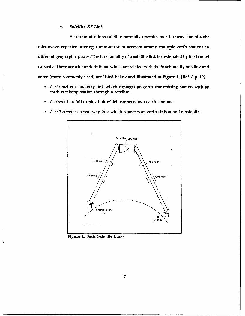
a. Satellite RF-Link
A communications satellite normally operates as a faraway line-of-sight
microwave repeater offering communication services among multiple earth stations in
different geographic places. The functionality of a satellite link is designated by its channel
capacity. There are a lot of definitions which are related with the functionality of a link and
some (more commonly used) are listed below and illustrated in Figure 1. [Ref. 3:p. 191
* A channel is a one-way link which connects an earth transmitting station with anearth receiving station through a satellite.
* A circuit is a full-duplex link which connects two earth stations.
* A half circuit is a two-way link which connects an earth station and a satellite.
S-1ellite repeater
s
I/2 circuit -. /- ' circuit
ChannlOI C{hannel
Earth sliionA
(Duplex)
Figure 1. Basic Satellite Links
7

The capacity of a link is designated by the types and numbers of channels
and the functional requirements of each channel. The channel-carrying capability of a
Satellite RF link is directly related to the overall available carrier-to-noise ratio. When one
RF link is planned, three basic factors are considered:[Ref. 1:p. 16]
" Uplink which represents the channel between a transmiitng earth station and asatellite. Its quality depends on the power of the transmitting earth station, the gainof the transmitting and receiving antenna and the system's noise temperature.
" Downlink which represents the channel between the satellite and the receiving earthstation. Its quality depends on the transmitter's power,the transmitting and receivingantenna's gain and the receiving system's noise temperature.
" Satellite electronics which produces undesirable noise signals. Their performancedepends primarily on intermodulation effects which cause several impairments.
The overall carrier-to-noise ratio present in the link is a combination of
three factors: the uplink carrier-to-noise ratio, downlink carrier-to-noise ratio and
electronics systems equivalent carrier-to-noise ratio which are related with the uplink,
downlink and satellite electronics mentioned above. Figure 2 shows an end-to-end satellite
communication link [Ref. l:p. 151.
b. Communications Subsystemn
From a communication point of view, a satellite may be thought of as a
faraway microwave repeater which receives uplink signals and after filtering, amplitication,
processing and frequency translation to the downlink band, retransmits them. So the main
parts of the communication subsystem are the communications repeater and the
communications antenna.
8

(1) Cotinunicationis Repeater
The communications repeater is an interconnection of many
channelized transponders and generally consists of four modules which are:[Ref.4 p.55J
" A wideband communications receiver/ downconverter.
" An input multiplexer.
* Channelized tri.veling wave tube amplifiers(TWTAs).
" An output multiplexer.
Use,cnvironment
Cn,tonen! ok
%VideoV (eo(Cvy)) 7 TentremI
Itek hki
at to,, t311on
Figure 2. End-to-end Satellite Communications Link
9
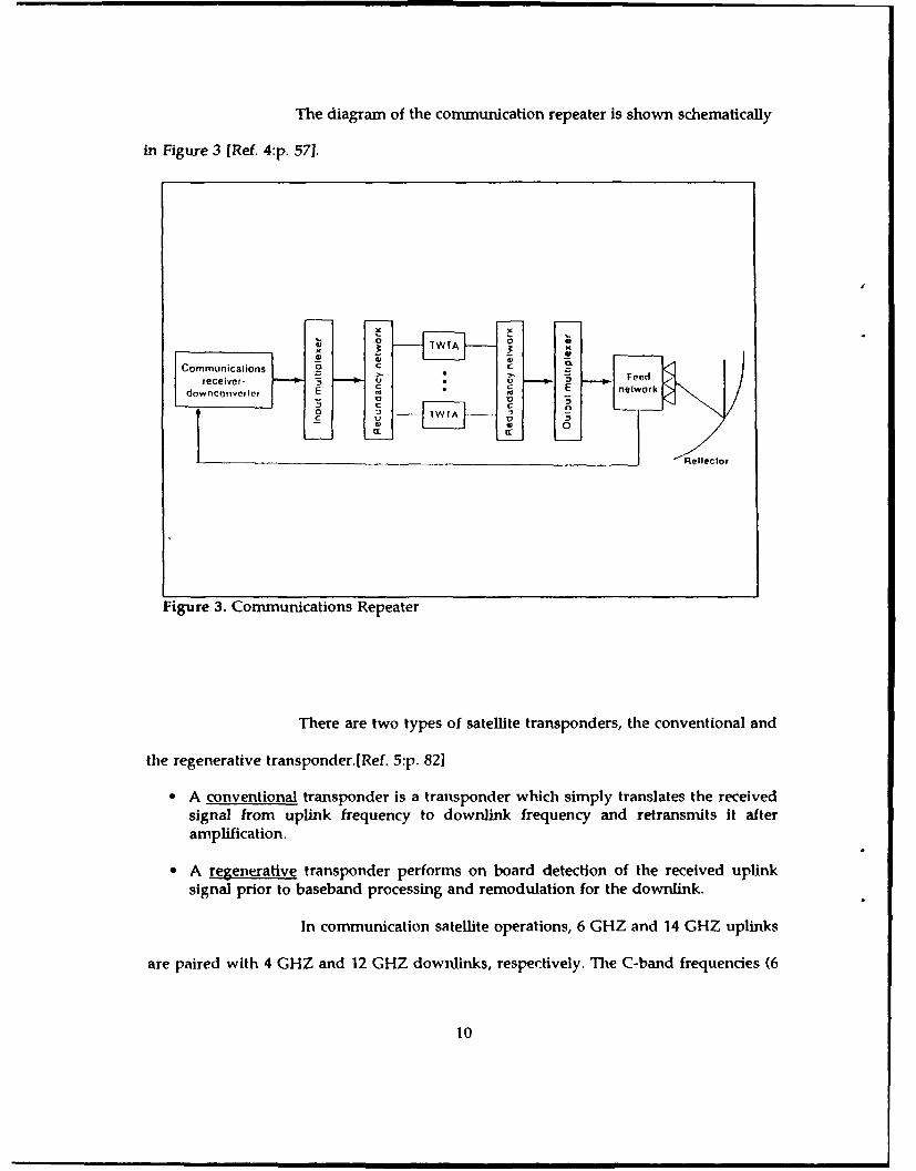
The diagram of the communication repeater is shown schematically
in Figure 3 [Ref. 4:p. 571.
~eflecIH
Figure 3. Communications Repeater
There are two types of satellite transponders, the conventional and
the regenerative transponderRef. :p. 82]
* A conventional transponder is a transponder which simply translates the receivedsignal from uplinik frequency to downlink frequency and retransmits it afteramplification.
* A regenerative transponder performs on board detection of the received uplink
signal prior to baseband processing and remodulation for the downlink.
In communication satellite operations, 6 GHZ and 14 GHZ uplinks
are paired with 4 GHZ and 12 GHZ downliks, respectively. The C-band frequencies (6
10
F

(6 and 4 GHZ) have the advantages of enough bandwidth, almost zero fading, low rain
loss and economic and reliable microwave devices.[Ref. 4 :p. 551
The wideband communications receiver/downconverter operates
within the 500 MHZ bandwidth designated for Uplink signals (5.9 to 6.4 GHZ and 14 to
14.5 GHZ for C and Ku-band respectively). After two filterings through a waveguide
bandpass filter, and two amplifications from a low noise amplifier, the signal is
downconverted to 11.7 to 12.2 GHZ or 3.7 to 4.2 GHZ downlinks. After downconversion,
the signal is amplified again and passes through a ferrite isolator to the input multiplexer.
The diagram of the wideband communications receiver/downconverter is shown in
Figure 4 [Ref. 4:p. 58].
t 4 GHz 14 GI It 12-131Z 12-Glitz
Low-noise Bandpass Bandposs GaAs FETamplifier litler Mixer filler amplilier
14.0- 14 5 Gi-lt .. ~ 1 12.2Gilt
U~plink D" ownlinksignals signals
2 3 GIlz(hom oscillator)
Figure 4. Wideband communications receiver-downconverter
The function of input multiplexer is to distinguish the 500 MHZ
bandwidth into transponder channels whose bandwidth depends on the satellite's mission.
11

The channelized TWTAs amplify the low-level downlink signal to a
high level for retransmission to earth. The TWTA is the major nonlinear device in a
transponder and is very important because it can influence the link performance.
Its size depends on the mission and is about 15 to 30 W for a 61 MHZ Ku-band
transponder. Nowadays, solid state power amplifiers based on gallium arsenide field effect
transistors have been developed and included in various satellites, such as SATCOM V,
TELSTAR 3, and INTELSAT VI. The expectation is that these amplifiers will provide longer
life and better reliability than TWTAs because of their superior linearity, which provides
greater communications capacity and is critical to modulation techniques. [Ref. 6:p. 1181
After the TWTAs, the downlink signals are combined by the output
multiplexer and retransmitted to earth.
(2) Conununications Antenna
The earth subtends an angle of about 18 degrees to a satellite in
geostationary orbit. If a satellite-mounted antenna is radiating energy equally in all
directions, a high percentage of this energy is lost to space. In order to increase the amount
of transmitter power which is actually transmitted to earth, the radiation must be
concentrated to the direction preferred. In microwave radio frequencies, this can be
accomplished by employing antennae with dish-shaped reflectors.
The main operation of the antenna is to provide shaped downlink
and uplink beams for transmission and reception of telecommunications signals in the
operating frequency bands.
To increase the communication capacity of the satellite frqTAMCY
reuse is applied with poariztion and beam separation methods. The polarization method
uses the principle that electromagnetic waves generally can be made to vibrate uniformly
12

in one of several planes or directions of polarization. The technique enables a single range
of frequencies to be re-used by arranging to transmit (and receive) with different
polarization to that applied to the initial use. The beam separation technique relies on the
fact that if two beams illuminate different regions without overlapping, then each beam
can employ the same frequencies without mutual interference.
Nowadays most communications satellites are equipped with several
antennae. The main categories of antennae are:[Ref. 6:p. 103]
" Omnidirectional.
" Global or earth coverage.
* Hemi/zone.
" Spot beam.
A typical arrangement of the communications subsystems, which
originates from the specification of the telecommunications package for the United
Kingdom UNISAT Satellite, is shown in Figure 5 [Ref. 6:p. 114]:
I'--
1AM_. 4 r
Figure 5. Communications subsystem diagram
13

c. Communications Satellite (spacecraft)
The spacecraft provides a platform on which the communication
equipment can operate and maintains this platform in the chosen orbit. The design of such
spacecraft is very complicated because it involves several branches of engineering and
physics. Satellite design and construction introduce several specific problems. First of all,
the very inaccessibility of a spacecraft for repair purposes necessitates strict reliability
requirements. Secondly, like any other equipment, satellites have a limited life span, and
for obvious economic reasons it is desirable that this is optimized with respect to
development and procurement costs. Finally, it has to operate effectively and efficiently in
the hostile environment of space, and this suggests quite unique engineering problems
which dictate equally unique solutions. For satellite communications system engineers, it
is valuable to have an understanding of the above problems and how the design and
construction process works.
In recent years, several spacecrafts have been developed for national and
regional markets. Basically, three generic communications satellites have been proven in
space and are summarized in the Table 1 below [Ref. 3:p. 10]:
Table 1. GENERIC COMMUNICATIONS SATELLITE
Manufacturer
BritishAerospace/
RCA Hughes Malta
Sitellhie Salcon Series 4(KX1 (IS 376 115 393 ECSTotal weight (kg) 601 750 540 to 661 IU0,] 61 to 68U
Tcal power (Walls) 100 - 1375 2260 90U - 1118 2250 I 11)
First Iaunch October 82 November 85 November 80 November 87 Juiie 83Lifetime (years) 10 I0 7 - 10 1t- 12 7
14

The cost of the communication package itself is only about 20% of the total
cost. The remaining cost is due to the platform and launch. If we exclude the
communication subsystem, which was described above, then in Table 2 we can see a the
subsystems and their main parameters, of a typical communication satellite: [Ref. 1:p. 1111
Table 2. SATELLITE SUBSYSTEMS
Principal Ounrt it tivcSV51cill rutici ion Char actcristics
Collmiiic. Iiolrs Rceisve, amlplify, process, I rrrn-illeir power.I ratslpoide is and[ ret ra osit signals; banudwidth G17,/iAnte nnas ca Pt nc and radiate bea lNrwidtit, orlient alion.,
Signals gain, single-carricr
.atnralcd flux dens-ityStructure Siippolr ISpace craft t i ider Resonaolt frequeincies,
huan ch and 01 bit at structural st re ngthIsenlvironmntn
Attitude control Keeps ntninas pointed at Role, Pitch, Ind yawcor rect earth localitin tocliccsan1d solar cell ptitttCrat the stil
Pfnir po%%cr Sitptly elct iicat powecr to Becgining of Life (1301-)spacecraft1 power, Eiid of Life (EEOL)
power; solstice and equinoxpowei-., eclips operatlioi
the r nial1 control Main taini so itable Spaccra ft incan tecmpe ratuoretemperanime ranges for latige and~ tenlipetatureallI sibt[)IScfts dutitug ranges; for all Criticallife. operatinig aind comlponlenisnonloperating. in and(out of eclipse
Prtopuilsion Mainitaiir orbital Position. Specific impuilske thrumtma 1or at titutde Control propellant masstori ccl ions, orbhital:cliatges. and initial orbitdecploytmenit
1 etemetry. trackitig. attd Mcirtitor spacccraft status;, Position and veocitycommiand (1T&C) orbital pat ametcrs, and nicasoring accuracv.
Control spacecraft tntmbter of Ile inc i crdoperaliion poitits. ntumbe r of
conltnidsComptereo spaccraft f'rovidr sailmfar-ttny Mas. ,tivnty power, dlesignt
corttrttnoicatiolts lifetimec reliability,operrations ini desit ed comniitiiationsorbit performane- noC1111ibe of
chiannels and t)1 c ofsignaul";

A communication satellite is usually stabilized that the communications
antenna points toward the earth on one hand, and the solar-energy-collecting system points
toward the sun for efficient collection of solar energy on the other. Two different kinds of
stabilization have been used in communications satellite design and they are:
* Spin stabilization
" Three axis or body stabilization
The schematic diagram for both stabilization techniques is shown in
Figures 6 and 7 [Ref. 7:pp. 46,481:
yYI
Figure 6. Spin-stabilized spacecraft Figure 7. Three axes stabilizedspacecraft
16

(1) Spin Stabilization
Usually a cylindrical satellite spins around its main axis of symmetry,
and is balanced so that the main axis is also one of the main axes of inertia. Thus, while
the satellite is in synchronous equatorial orbit, the main axis is parallel with the earth's
geographic polar axis. For a stable spinning condition, the ratio of the moments of inertia
of the spacecraft must satisfy the relationships: [Ref. 7:p. 46]
ly/Ix >1 (1)
Iy/Iz >1 (2)
Typical inertia ratios range from 1.1 to 1.3, and a typical spin speed
is IOOr/min. Spin-rate maintenance can be achieved through metered impulses by boosting
the secondary propulsion jets. [Ref. 7 :p. 46]
Spinning satellites can reach attitude accuracy on the order of a few
tenths of a degree. While the spacecraft is spinning, the communications antenna has to
be vointed towards the earth. In order to achieve this, it's necessary to detect the local
vertical and both decouple the antenna mount from the spinning main body and despin
the mount. This process can be done either electronically or mechanically.
(2) Three Axes Stabilization
Communications satellites in geostationary orbits are often stabilized
in three axes with respect to a geocentric system that rotates with the earth. For a body
stabilized spacecraft, these three axes appear to be stationary to an observer located at the
earth's surface point, point P in Figure 7. Although it appears to an observer at point P that
it is stabilized, it has an angular motion with respect to inertial space in order to maintain
17

its axis z along the local vertical GO. This angular velocity is called "pitch rate", and for a
synchronous orbit it is equal to the earth's angular velocity. [Ref. 7 :p. 49]
l7.27x10-5 rad
Antenna and solar panel pointing requirements are solved using the
same techniques as in the spin stabilization case mentioned above.
d. Earth Station
One of the main elements in a satellite link is the earth station. The earth
station is the collection of equipment on the surface of the earth which is used for
communication with the satellite, regardless of whether the equipment is a fixed, ground
mobile, maritime or aeronautical terminal.
The performance of an earth station is specified by its equivalent isotropic
radiated power (EIRP) and its gain-to-system noise temperature ratio (G/T). EIRP is the
product of the power output of the high power amplifier at the antenna and the gain of
the transmitting antenna. The receiving system sensitivity is determined by G/T, which is
the ratio of the receive gain of antenna to the system noise temperature. For a 10m earth
station this is 33db/k and for a satellite receiver system it is -6db/k.
The block diagram of an earth station is shown in Figure 8.
(1) Earth station antenna
The earth station antenna is an important part of the RF terminal. It
serves for both transmission and reception, but not necessarily simultaneously.
18

4,-4..,
P .nIlnn0,eficlo,
D.'wnlmok-
Figure 8. Block diagram of an earth station
The antenna subsystem consists of the antenna proper, typically a reflector and feed;
separate feed systems to permit automatic tracking; and a duplex and multiplex
arrangement to permit the simultaneous connection of many transmit and receive chains
to the same antenna.
The earth station antenna has to satisfy three main requirements
which are: [Ref. 4:p. 711
e Highly directive gain in a given direction that is the ratio of the maximum radiationintensity produced in that direction, to the maximum radiation intensity producedin the same direction from a reference antenna with the same power input.
G 4 xn
* Low noise temperature so that the total noise temperature that limits the sensitivityof the earth station, which is proportional to the antenna temperature, can be keptlow.
19

* Easily steered so that a tracking system can comprise whatever control limits anddrives are necessary to keep the antenna pointed at the spacecraft which results theminimum antenna pointing loss.
The two most common types of earth station antennas, which satisfy
the above requirements, are the parboo antenna with a focal point feed and the
caseegrain antenna [Ref. 4:p. 71].
The paraboloid antenna consists of a reflector and a feed. On the
transmission section, the signal energy from the high power amplifier is radiated at the
focal point by the feed. This illuminates the reflector, which reflects and focuses the signal
energy into a narrow beam. On the receive section, the signal energy captured by the
reflector converges on the focal point and is received by the feed, which then directs it to
the low noise amplifier. This type of antenna is easily steered and has a gain efficiency of
50-60%. The only disadvantage is that sometimes there is high antenna noise distribution.
This is paricularly troublesome when the antenna has a high elevation angle, because the
feed illuminates the ground which has high noise temperature.
The cassegrain antenna is a dual reflector antenna. It consists of a
paraboloid main reflector, whose focal point is coincident with the virtual focal point of
a hyperboloid subreflector, and a feed whose phase center is at the real focal point of the
subreflector. During transmission, the signal energy from the high power amplifier is
radiated at the real focal point by the feed. This illuminates the surface of the subreflector,
and reflects the signal energy back to the main reflector, where it is reflected again to form
the antenna beam. During reception, the signal energy captured by the main reflector is
directed toward its focal point. From this point the subreflector again reflects the signal
energy back to its focal point where the feed receives the incoming signal energy and
directs it to the low noise amplifier. This type of antenna is more expensive but has
20

advantages over the paraboloid, such as low noise temperature, better pointing
accuracy,and flexibility in feed design. Both types of antennas are shown in Figures 9 and
10 below (Ref. 4:pp. 72,731.
P.,mbot.O.
,... \ po0.! ,,NN
I•1 z 1 *" e ..... ' "h .o*W.'. M- ...
Figure 9. Paraboloid antenna Figure 10. Cassegrain antenna
(2) Receivers
To receive a signal from a satellite, several distinct functions must be
performed. The signal must first be amplified, then reduced to a lower frequency so that
is convenient for further amplification and demodulation, then demodulated and delivered
to baseband processing equipment.
As used in this thesis, the term receiver chain means specifically low-
noise amplifiers, down converters and demodulators. Down conversion can be
accomplished either in one step, going directly from the satellite downlink carrier
frequency to the intermediate demodulator frequency, or in several steps. Usually two
stage down conversion is used when the same receiver is to be tuned to a multiplicity of
channels.
21
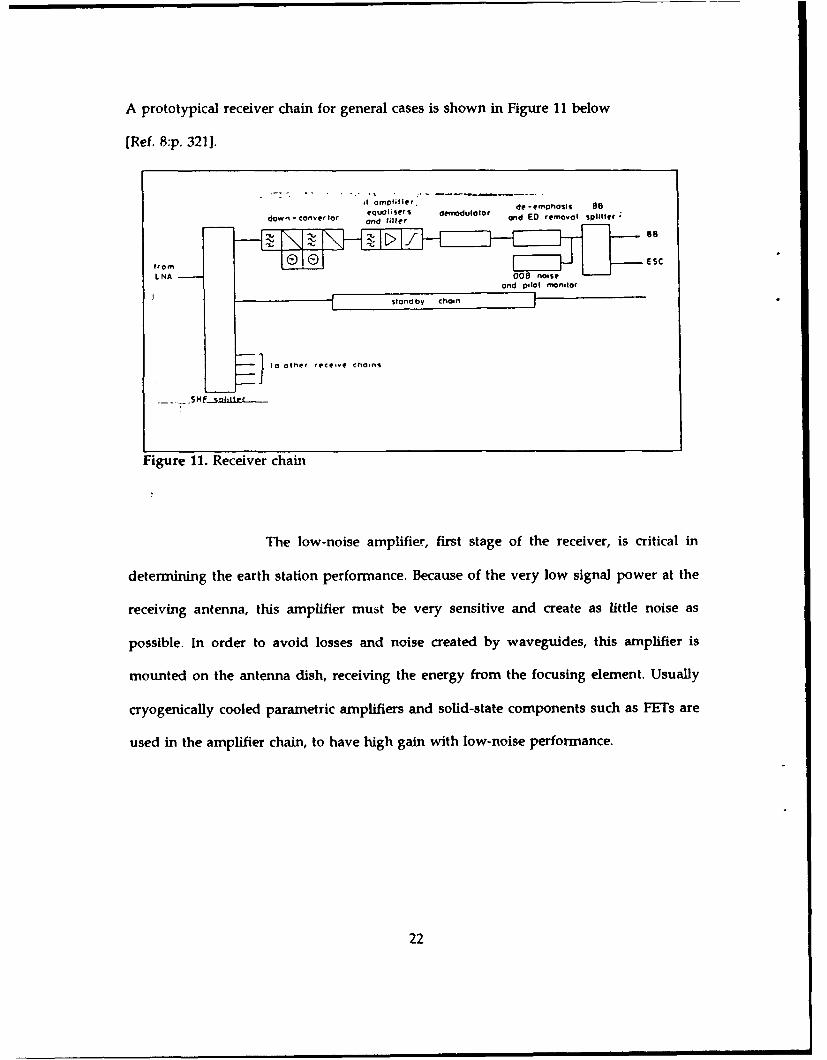
A prototypical receiver chain for general cases is shown in Figure 11 below
[Ref. 8 :p. 321).
"it m plifer . de -em Phosis 88
dowl- converfor equalers demodulotor and ED removal splitter
doV °Covrtr on ile
fromES
L NA 000 noiseand pilot monilo¢
Ss l o d b y c h a ,i n
I to other reteive chains
Figure 11. Receiver chain
The low-noise amplifier, first stage of the receiver, is critical in
determining the earth station performance. Because of the very low signal power at the
receiving antenna, this amplifier must be very sensitive and create as little noise as
possible. In order to avoid losses and noise created by waveguides, this amplifier is
mounted on the antenna dish, receiving the energy from the focusing element. Usually
cryogenically cooled parametric amplifiers and solid-state components such as FETs are
used in the amplifier chain, to have high gain with low-noise performance.
22

The noise introduced by the amplifier is calculated by: [Ref. 7:p. 103]
N=kxBxT
where k=Boltzmann's constant=l.38x1 0^-23 j/k
B=Bandwidth in hertz
T=Effective input noise temperature in kelvins
In addition to the receiver electronic equipmeni noise, antenna noise,
as well as atmospheric and cosmic sources, must be added at the receiver inp, .Thus, the
tota" noise temperature that limits the sensitivity of the earth station is a combination of
the following: [Ref. 7:p. 103]
- Sky noise, atmospheric absorption, and rain.
- Transmission-lines losses including the feed losses.
* Receiver system temperature.
* Antenna noise temperature.
(3) High power amplifier
A high power amplifier usually uses a Traveling Wave Tube (TWT)
or a Klystron. If multicarrier function is anticipated, the total power of the amplifier must
be substantially higher than the power per carrier in order to avoid intermodulation
products. This is necessary because of the nonlineAr characteristics of these devices when
operated close to saturation level. The traveling wave tube can achieve a bandwidth on the
23

order of 10%;hence, it can cover the entire 500 MHz allocated for satellite communications.
The Klystron amplifier can provide higher gain and better efficiency than the TWT but at
a much smaller bandwidth, on the order of 2%. For low power applications, lmpatt diode
amplifiers or GaA, , ET amplifiers can be used with better efficiency than the TWT or
Klystron amplifiers.[Ref. 4:p. 941
(4) Upconverter
The upconverter accepts the modulated IF carrier from the carrier
modulator and translates its IF frequency to the uplink RF frequency by mixing the IF
frequency with a local oscillator frequency. In Figures 12 and 13 below, a single and a dual
conversion are shown [Ref. 4:p. 107]:
Bandpass
w0 b (h)II
Figure 12. Upconverter, singleconversion Figure 13. Upconverter, dual conversion
(5) Primary pwer
Primary power systems vary from plain battery or solar-cell-operated
remote transmitters for data gathering to huge combined commercial power and diesel
generator systems for large stations. Almost all transmit and receive earth stations require
24

some kind of uninterruptable power system, that is, emergency power to continue the
communications during commercial power outages. Almost all systems today use batteries
to effect this transition. Some systems have been devised in which motor generators store
enough energy in flywheels to permit a smooth mechanical transition.
e. Terrestrial link
From the earth station, the signal is carried to the customers' premises
through a terrestrial transmission medium. For this purpose, coaxial cable, fiber-optic cable,
twisted-wire pair, microwave links, etc., can be used. The nature of the signal and the
distance to be carried will affect the cost and the method which will bc used. Fiber optics
are most appropriate for broadband signals over a few kilometers distances, twisted-wire
pair for narrow-band signals over short distances and microwave links for multiplexed
broadband signals over long distances.
To provide adequate satellite service to a user, the service requirements
must be well specified in terms of quality. Quality of service, specified in terms of
parameters such as link availability, bit error rate, transmission rate, and signal-to-noise
ratio may be translated into a required carrier-to-noise ratio (C/N)r in the RF link. The
required (C/N)r is then compared with the available carrier-to-noise ratio (C/N)a to
determine the overall link's capacity. In order to achieve the required quality several basic
baseband processing stages must be considered, including: [Ref. 3:p. 221
* Source coding and/or modulation, where a source signal is coded in digital form orprocessed in analog form to be ready for terrestrial transmission and multiplexing.In analog transmission AM and FM modulation is used, while in digital PCM isused.
1 AM=Amplitude Modulation
FM=Frequency ModulationPCM=Pulse Code Modulation
25

" Multiplexing where in analog transmission FDM is used while in digital
transmission TDM is used.2
" Channel coding.
" Multiple access where FDMA is the most common method in use, because it wasa natural extension of the FDM systems that were in use for many years in terrestrialcarrier systems. It employs multiple carriers within the same transponder. We canalso use TDMA which employs a single carrier which is time shared among manyusers, and CDMA wherein all uplink signals occupy the same frequency band at thesame time."
2. Orbits
a. General
Generally speaking there are four types of orbits which might be suitably
used today for satellite communications. These are:
* Low earth orbit (< 300 miles above earth's surface)
* Medium earth orbit ( 7000-8000 miles above earth)
* Geosynchronous orbit (exactly 22,238 miles above earth).
* Super synchronous orbit (between geosynchronous and lunar orbits).
Low earth orbits are used most often because they are the easiest and least
expensive. The possible applications and uses of this orbit are reconnaissance, vacuum
experiments, localized weather,resource imaging, etc.
Medium orbit satellites are normally launched into a polar orbit and are
programmed when they pass over the earth to stay in the sun's illumination.This is
2 FDM=Frequency Division Multiplexing
TDM=Time Division Multiplexing
FDMA=Frequency Division Multiple AccessCDMA--Code Division Multiple AccessTDMA=Time Division Multiple Access
26

important for remote sensing and weather monitoring. This type of orbit is also suitable
for navigational purposes.
Geosynchronous orbit is a single very precise orbit which allows a satellite
to complete one revolution around the earth every 24 hours.
b. Foundation of the theory
The most accessible way of developing orbital mechanical theory, at least
as applied to earth satellites starts with Newton's law of gravitation, and the second law
of motion.
The characteristics of a satellite orbit are ruled by Keppler's laws that is,
" The orbit of each planet (satellite) is an ellipse with the sun (earth's center) at afocus.
" The line joining the planet (satellite) to the sun (earth's center) sweeps out equal•areas in equal times.
" The squares of the orbital periods of two satellites have the same ratio as the cubesof their mean distances from the center of the earth.
c. Orbital perturbations
The earth's distorted shape, the atmosphere, the presence of the sun and
moon, and other factors give rise to a series of important orbital perturbations. They affect
both the launch sequence and the final operational orbit, and influence the design of the
spacecraft in many ways. In a typical geostationary communications satellite, provisions
for dealing with the gravitational effects of the sun and moon and anomalies of the earth's
gravitational field normally add from 20-40% to the total dry mass of the spacecraft in
station-keeping propellant. [Ref. 1:p. 461
27

Orbital perturbation of artificial satellites can be placed into three
categories:
" Those due to the presence of other large masses (i.e., sun and moon).
" Those resulting from not being able to consider either the earth or the satellite as apoint mass.
* Those due to nongravitational sources such as the radiation pressure of the sun, theearth's magnetic field, micrometeorites, and atmosphere.
d. Geostationary orbit
Three-fourths of the cost of a communications satellite is related to
launching and maintaining it in its operational orbit so that the communications package
can function satisfactorily. Although a number of different orbits have been used for
special purposes in satellite communication, and will continue to be used, the main interest
for this application is in the geostationary orbit. This is a circular orbit whose period of
rotation is equal to that of the earth's and whose plane is in the plane of equator. Figure
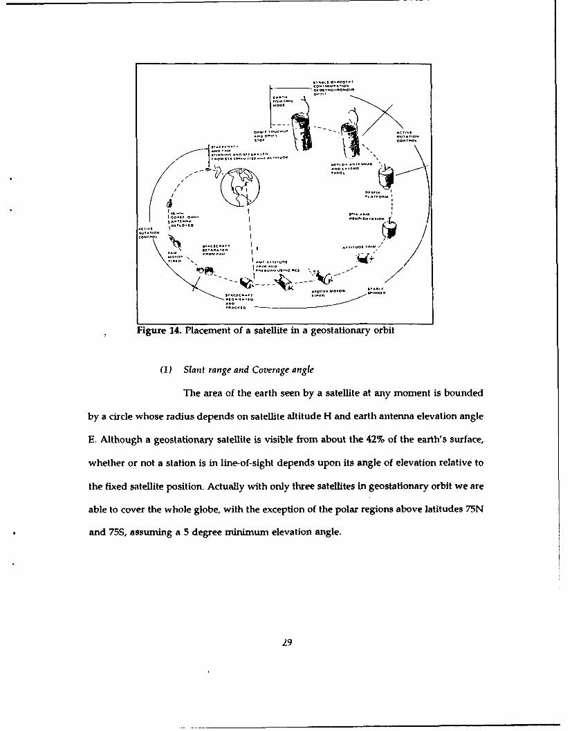
14 shows a placement of a satellite, launched from Cape Kennedy, in geostationary orbit.
[Ref. 4:p. 491
28
s1 ! ltS!
I
The arao teer see by a a,'t a ay omntibone
S.AC.nN,N O S n~l~~AfV
E. Although ageostatinar steffite i~s vile fro abu te42 f erh' urae
Al-. - ,*,o A. ,,~
.. AVAYAAO It.
p~l~o P AVVO 1)0
'flY| D 4 1
A? 041!
Figure 14. Placement of a satellite in a geostationary orbit
(1) Slant range and Coverage angle
The area of the earth seen by a satellite at any moment is bounded
by a circle whose radius depends on satellite altitude H and earth antenna elevation angle
E. Although a geostationary satellite is visible from about the 42% of the earth's surface,
whether or not a station is in line-of-sight depends upon its angle of elevation relative to
the fixed satellite position. Actually with only three satellites in geostationary orbit we are
able to cover the whole globe, with the exception of the polar regions above latitudes 75N
and 75S, assuming a 5 degree minimum elevation angle.
29

The coverage geometry is shown in the Figure 15 below [Ref.4 p.441,
Sailelihe
Figure 15. Coverage angleand Slant range
where the earth coverage angle 2a(max) is the total angle inclined by the earth as seen by
the satellite.
The communication coverage angle 2a is similarly defined by the
equation:
2a=2xsin- 1(-- xcosE)R..H
where Re is the assumed's spherical earth radius, H is the altitude of the satellite orbit, and"'
E ishee the eathov angle i n the earth station antenna.
Fota geostationaryobit the altitude H of a satellite is 35,786 Km and
Re is assumed to be about 6,378 Km thus if we put E--0 degrees then the earth coverage
30
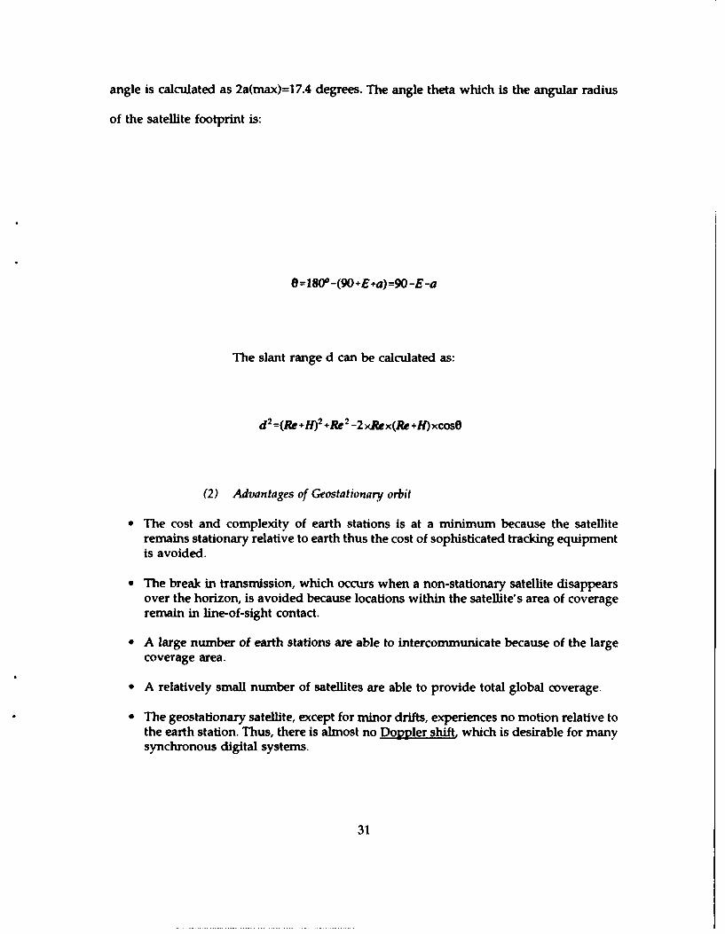
angle is calculated as 2a(max)=17.4 degrees. The angle theta which is the angular radius
of the satellite footprint is:
e--80Y-(90+E+a)-90-E-a
The slant range d can be calculated as:
d2 -(Re +f) 2 +Re 2-2 xRex(Re +Ixcose
(2) Advantages of Geostationary orbit
* The cost and complexity of earth stations is at a minimum because the satelliteremains stationary relative to earth thus the cost of sophisticated tracking equipmentis avoided.
* The break in transmission, which occurs when a non-stationary satellite disappearsover the horizon, is avoided because locations within the satellite's area of coverageremain in line-of-sight contact.
* A large number of earth stations are able to intercommunicate because of the largecoverage area.
* A relatively small number of satellites are able to provide total global coverage.
0 The geostationary satellite, except for minor drifts, experiences no motion relative tothe earth station. Thus, there is almost no Doppler shift which is desirable for manysynchronous digital systems.
31

(3) Disadvantages of geostationary orbit
" Latitudes greater than 81.5 degrees North and South are not covered; this is reducedto 77 degrees North and South if antenna's elevation angle is less than 5 degrees.
" The received signal strength is very weak, because of the great distance (signalstrength is inversely proportional to the square of the distance). It is on the order of1 picowatt.
" The signal propagation time is aiso proportional to distance. At 270 milliseconds(average), this is sufficient to affect the transmission efficiency.
" Compared with lower orbits, more powerful rocketry and fuel supplies are needed
to achieve geostationary orbit.
" With increasing altitude, the effects of earth and moon eclipses are increased.
" The free space loss increases with the increase of distance.
3. Multiple Access
a. General
Communication satellites demonstrate that satellite repeaters can provide
a communication capacity equal to or greater than that available by other means, and a
single communication satellite can provide many communication channels between widely
separated points. Generally, the various earth stations accessing a satellite are not similar
to each other, because their size, capacity, and operation frequency depend on the
requirements of the network they serve. A single earth station may access one or more
transponders and it may use one carrier per transponder or multiple carriers per
transponder. In turn, it may receive one or several carriers. Thus, each satellite transponder
may be accessed by one or more carriers. As a result, and because each transponder is a
nonlinear repeater with limited power and bandwidth, a serious network problem exists.
This becomes more complicated if the communication requirements for each node change
32

from second to second. To satisfy these access requirements some modulation techniques
have been developed. The most frequently used are:
* Frequency-division multiple access (FDMA).
" Time-division multiple access (TDMA).
" Code-division multiple access (CDMA), which is subdivided into spread-spectrummultiple access (SSMA) and pulse-address multiple access (PAMA). SSMA utilizesangle-modulation coding and PAMA utilizes amplitude-modulation coding.
b. Frequency-division multiple access
In frequency-division multiple access, the repeater bandwidth is divided
into a number of nonoverlapping frequency bands which form access channels. Each link
is assigned an access channel. If more than one FDMA carrier accesses the same
transponder, the transponder's nonlinearities dictate a back-off and this reduces the total
transponder capacity. To improve multicarrier operation, hard-limiting transponders could
be used.
Whenever two or more independent signals pass through a hard-limiting
repeater, the power ratio of any two component signals at the output will generally differ
from the power ratio of the same two components at the input, the change supporting the
stronger signal at the expense of the weaker one.
There are two main FDMA techniques in operation today. These are the
multichannel-per-carrier transmission, and the single channel-per-carrier transmission. In
multichannel-per-carrier transmission or FDM-FM-FDMA the transmitting earth station
frequency division multiplexes several signal sideband suppressed carrier telephone
channels into one carrier baseband assembly. This frequency modulates a RF carrier and
is transmitted to a FDMA satellite transponder. In the single channel per carrier technique
(SCPC), each telephone channel independently modulates a separate RF carrier and is
33

transmitted to a FDMA satellite transponder. The modulation can be analog, such as FM,
or digital, such as PSK [Ref. 4 :p. 1941.
Figure 16 shows a 36 MHz transponder frequency assignment with four
FDMA carriers. The receiving earth stations separate the carriers by using the appropriate
filters. In deciding on the frequency assignments for each carrier, one must consider three
basic factors:
" Total useful bandwidth per transponder.
" Available power and uplink power control capability.
" Interference.
The advantages and disadvantages of FDMA are summarized as follows
[Ref. 7:p. 293]:
(1) Advantages of FDMA
* Channel availability is fixed.
No central control is required.
Users with several capacity needs are easily served.
Relatively unsophisticated earth stations (simplicity).
(2) Disadvantages of FDMA
Intermodulation requires back-off, reducing transponder throughput.
The system is vulnerable to jamming.
Rigid system; reassigning resources to reflect traffic change is difficult.
= 36 MHz -
Figure 16. FDMA frame structure
34

c. Time-division multiple access
All the stations in a TDMA system transmit on the same carrier frequency.
In some relatively lightly-loaded systems, the earth stations transmit at random, but TDMA
systems serving fixed stations carrying relatively heavy traffic are mainly ordered systems
in which each station waits for its turn to transmit a burst of data in accordance with a
prearranged time plan.
Generally, a TDMA system is a true orthogonal system, since only one
carrier operates at a given time. As a result, the nonlinear nature of the transponder is
minimized, no multicarrier interference is generated, and the full power of the transponder
is available as well as the full bandwidth. This technique is an energy-efficient technique,
however, TDMA requires network synchronization, coded messages, and buffer storage
from burst to burst. The message must be coded in order to provide address, timing, and
other pertinent information. Short guard intervals (of the order of 1 microsecond) are left
between bursts to allow for small timing errors. In order to accomplish the above functions
a certain loss of efficiency occurs. A TDMA system can attain more than 90 percent
efficiency of satellite power utilization. In contrast, a FDMA system may lose 3 to 6db of
the available power. Since the transponder never has to amplify more than one carrier at
a time, there is no intermodulation and no significant back-off is necessary; it is therefore
possible to use practically all the power which the output amplifier can deliver.
Each earth station must [Ref. 8:p. 224]:
* Store the information that arrives from the terrestrial network and which willcomprise its next burst of transmission and transmit it at the precise time necessaryto ensure that, when it arrives at the satellite, it does not overlap the leading orsucceeding bursts.
35
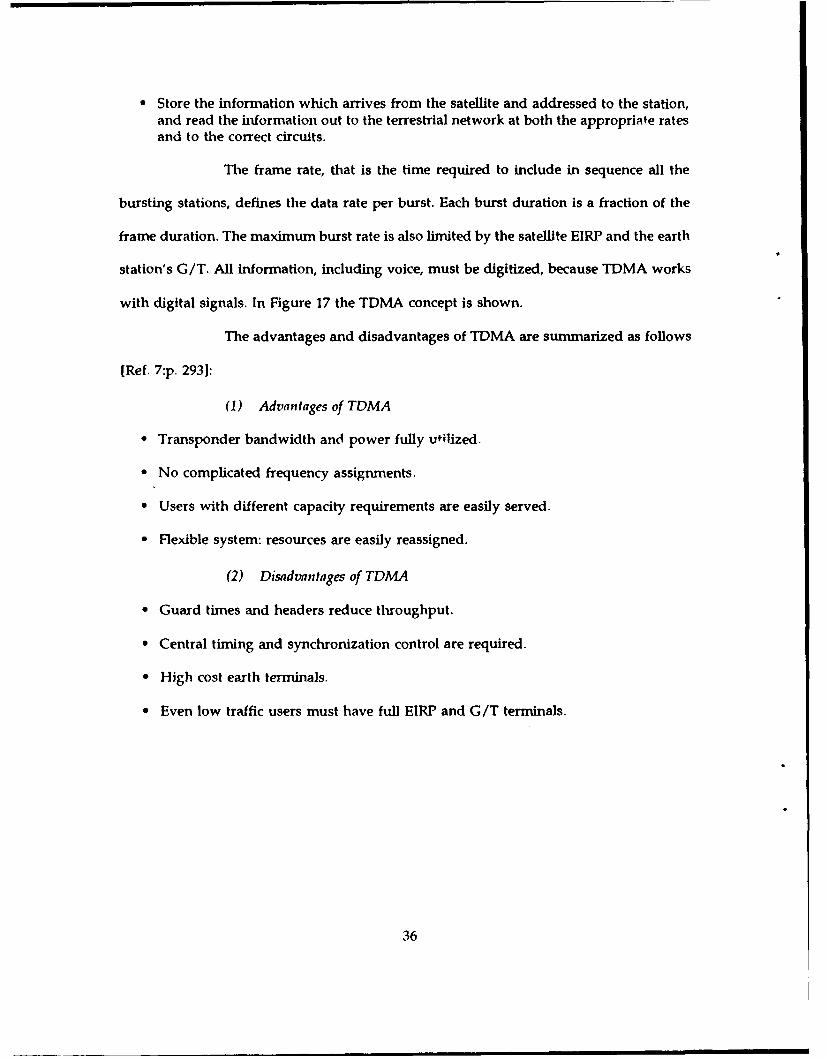
* Store the information which arrives from the satellite and addressed to the station,and read the information out to the terrestrial network at both the appropriate ratesand to the correct circuits.
The frame rate, that is the time required to include in sequence all the
bursting stations, defines the data rate per burst. Each burst duration is a fraction of the
frame duration. The maximum burst rate is also limited by the satellite EIRP and the earth
station's G/T. All information, including voice, must be digitized, because TDMA works
with digital signals. In Figure 17 the TDMA concept is shown.
The advantages and disadvantages of TDMA are summarized as follows
[Ref. 7 :p. 2931:
(1) Advantages of TDMA
• Transponder bandwidth and power fully utilized.
" No complicated frequency assignments.
" Users with different capacity requirements are easily served.
* Flexible system: resources are easily reassigned.
(2) Disadvantages of TDMA
" Guard times and headers reduce throughput.
" Central timing and synchronization control are required.
* High cost earth terminals.
" Even low traffic users must have full EIRP and G/T terminals.
36

SAN FRANCISCO 4
TO ALLNEW YORK STATIONS
LO ANGELES
Figure 17. TDMA network
d. Code-division multiple access
In code-division multiple access operation, several stations use the same
carrier frequency and associated bandwidth at the same time. This activity uses a techniquc
which lies within the broad area of spread-spectrum communications and application is
limited to digital transmissions.
One way of generating a CDMA transmission is to combine a chain of
pseudo-random pulses with the message signal. The pulse repetition rate of the pseudo-
random signal must be high enough to spread the signal over the whole of the available
bandwidth. One message bit is therefore combined with a dain of many pseudo-random
bits. For example, the message might have an information rate of 50 Kbits/s and the
pseudo-random sequence might have a chip rate of 5 Mbits/s so that every message bit
is combined with 100 chips. The receiving station knows the pseudo-random sequence and
is able to generate a chip chain which is consistent with the intended transmission. Thus,
the receiving station is able to unscramble the message by a process analogous to coherent
37

detection. All the other transmissions, which are combined with different pseudo-random
sequences, look like noise. The signal-to-noise power ratio is proportional to the number
of chips per bit and the quantity 10log(chips per bit) is called processing gain.
As a consequence of the processing gain relationship, the number of
stations which can be served in the same band by CDMA techniques is largely determined
by the number of chips per bit. Another important factor is the degree of equality between
the received power levels from the different stations. If considerable differences exist, the
ratio of the weaker signal-to-noise-plus-other-signals may be too small, even with the
advantage of the processing gain, to allow extraction of the data message with small bit
error rate.
The advantages and disadvantages of CDMA are summarized as follows
[Ref. 7:p. 293]:
(1) Advantages of CDMA
" No central control; fixed channels.
" All earth terminals interchangeable.
" Earth station sophistication is at baseband.
* Relatively immune to external interference.
(2) Disadvantages of CDMA
* Transponder must be backed off; reduced throughput.
* Only a limited number of orthogonal codes exists.
* Works efficiently with preselected data rates.
38
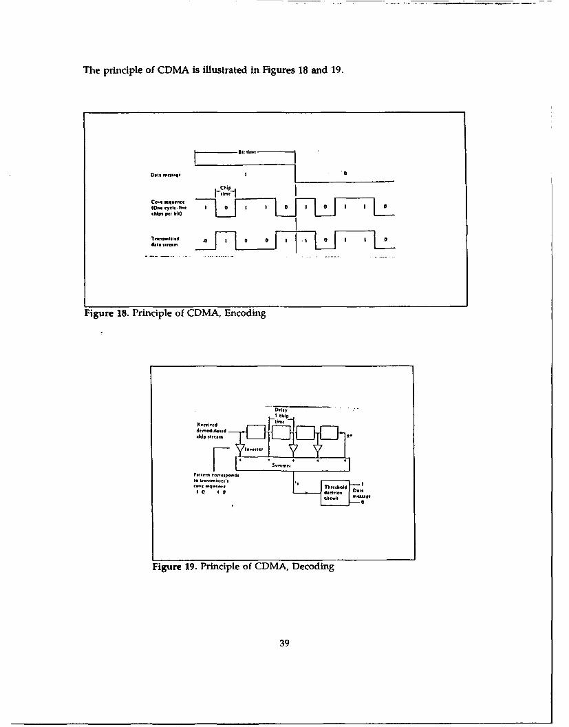
The principle of CDMA is illustrated in Figures 18 and 19.
sit time,
Data M I~t 1
ships par bit)
Figure 18. Principle of CDMA, Encoding
dripI thipa
Palmer. C~ntime
t0 t-SisO
Figure 19. Principle of CDMA, Decoding
39
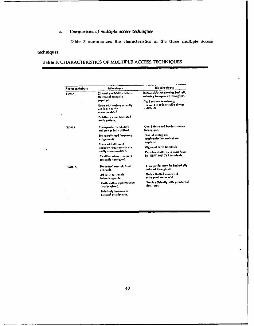
e. Comparison of multiple access techniques
Table 3 sunu-narizes the characteristics of the three multiple access
techniques.
Table 3. CHARACTERISTICS OF MULTIPLE ACCESS TECHNIQUES
Amous lecIonlotit AJmlg Dudvantages
uas1 .1111 TAI~ cuadtly wovner"' to rellect trooihe Change
Peal I e t-0-iJ Is difficult.
I17NMA Tiamponil.i.nqi~tltlb cloedr liners and headers redlueemil ean paar fully ultIlen. 111,14,1111..
fNr ronaplicatleleey Cevile1 tiing anad
aseigenaeate. sylveia~prrallirsf C0111,91 mrs
Ulmr wii dilloel wsatea*lf41
capaitly requlwronea'lt ere iliglo-tot ctutiale oaInalt.eaily anrvramoiltf. r-t loarirCmc usrs. allt hae
rinfll sysilna aegalaaes lull Ef117 and C/T teamleas.
Ste easily reassigned.
CUNIA He aanlaal enimtagI: ale lienspre"Jner milli 6 4e l Voie llgcliannelt. reilioceel 1tiauaglopail.
All erslls leaaaat~ala Ocaly a lrnittil ,Iatfliaf oft"elcliaaatlle. eflinag'al evaJes sill.
s"Ilapuliaaa icaaitiea" Wmki~ elliently will% 1pateileel
Isat 620b66"jis. dale roesd.
Aeit.1t1ly lacrvunfi 10extenal l11ctele(.
40

C. SPECIAL PROBLEMS IN SATELLITE COMMUNICATIONS
The development of modem satellite communications technology using satellites in
geostationary orbit has generated many new services and capabilities not practical when
using terrestrial systems. The unique geometric advantage of a satellite in stationary orbit
allows multiple access by many earth stations on the earth's surface through a single
satellite repeater. This high altitude repeater creates long-distance, wideband network
facilities at low cost compared to other media. A result of the high altitude of the
geostationary orbit is the rather long transmission time delay which can create undesirable
subjective effects of echos on voice circuits, reduced throughput efficiency on data circuits,
and synchronization problems for digital transmission.
1. Speech echo
At geostationary altitude, it takes about 270 milliseconds for signals to travel
from the transmitting earth station through the satellite to the receiving earth station. The
extent to which speakers notice and are affected by echo depends, greatly on both its
loudness and the time which elapses between the speech and its echo. There are two
techniques in use for controlling echo on satellite circuits, echo suppression and echo
cancellation.
a. Echo suppression
Echo suppressors used on satellite channels employ digital technology, and
apart from having several other advantages, they have a fax faster reaction time than
analogue suppressors. The available model of a suppressor can be programmed to allow
a weaker signal to break in sooner, thereby reducing the amount of speech clipping.
41

b. Echo cancellation
Echo cancelers overcome the inherent conflict present in echo suppressors
by automatically synthesizing a replica of the expected echo on the receive path, and then
subtracting it from the echo when it is received, thus canceling the echo component of the
received signal.
2. Data transmission
The economics of long-distance telecommunications via satellite has created
many new applications, services, and opportunities for data communication users.
Unfortunately, the computer communications protocols, data modems, and echo control
devices developed originally for terrestrial networks are not suitable for use in the long-
time delay environment of satellite communications. The impact of the delay on data
circuits can be measured in terms of reduction in data throughput efficiency, plus potential
modem and protocol malfunction due to mishandling of delayed echoes.
a. Protocols
A set of rules that govern the exchange of data between information
systems is called a protocol. A protocol can be regarded as a specialized and self-contained
communications system in miniature. Its rules will hiitiate and perform specific actions,
either on request or in response to some event. The most important functions and
properties of a data link control protocol are:
* Link Initiation and Ternination.
" Synchronization.
* Link control.
" Error Detection and Correction.
" Flow control.
42

There are three basic classes of protocols in use nowadays, which are
sununarized below and illustrated in Figure 20 [Ref. l:pp 374-3761
" Block-by-block transmission.
" Continuous block transmission with restart after error detection.
* Continuous block transmission with selective block repeat.
0 0. ,
II
< 4 . z <00
W WL WL
S" = One-way. satellitedelay 320 ms
0 .
U .. 0l
L < - L00
WF W
Figure ~ ~ dla 320 Bai cass fpotclz 0
<] U] U ! U
S = Ou-way satellitedelay -- 320 mus
Figure 20. Basic classes of protocols
43

3. Digital network synchronization
A satellite in geostationary orbit does not remain exactly stationary. Departure
from a stationary position is influenced by a number of factors, including the earth's
nonsymmetrical gravitational field and perturbations caused by the sun and moon.
Inaccuracies in correcting satellite position and adjusting orbital parameters also contribute
to the nonstationarity of the orbit. Although the total change in position translates into a
change in transmission time of less than 0.5%, the variation is significant enough to require
some compensation on satellite links exchanging digital data with synchronous terrestrial
networks. In order to solve this problem, an elastic buffer (digital interface) is inserted
between the satellite facilities and the terrestrial network, as shown in Figure 21 [Ref. 1:
p.38 4]
Data Datac o i n I I k i l i c a i o l ' % I D q ig i t l i t l e r f a c e d p i t a l
facilities (claIstic buffrl) rdigwo.
S clock T clock
Figure 21. lnte:face between satellite system and terrestrialfacilities
D. RELIABILITY OF SATELLITE COMMUNICATIONS SYSTEMS
1. General
Reliability , as a function of time, is the probability that a component will not
fail before time t. For satellite communications systems, reliability depends on two main
parts of the system, the satellite and the ground segment. The primary measure of system
effectiveness is called operational availability and refers to the total time during the
44

mission's duration when the system or the equipment is capable of meeting specified
performance standards. This may be defined as the ratio of time available when needed to
total time needed.
For satellite communications systems, availability depends on the launch's
success, number of operational satellites, replacement time and back-up satellites [Ref.5
p.3551. Operational availability normally depends on reliability, maintainability and supply.
Thus, for satellite communications systems, availability depends only on reliability, because
maintainability and supply are not possible.
2. Classes of failure
Since reliability deals with performance for a given time, or with the
accomplishment of a certain mission of a specified duration, it is logical to study failures
from a time-characteristic point of view. Generally failures are classified into three
categories, in which the last two are particularly relevant for complex equipment such as
a satellite. [Ref. 5:p. 3551
* Initial failures which are caused by a defect present at the time the equipment wasfirst put into operation.
" Chance or random failures which result from unavoidable, unpredictable or unusuallysevere stresses that exceed the failure resistance of the part or component during itsuseful life period. The breakdown of a capacitor as a result of a transient surge ofvoltage is an example.
" Wear-out failures which result from the depletion of some material or propertynecessary for the proper operation of a component. This depletion may be caused byabrasion, chemical reaction etc. For example, the chemical exhaustion of dry cellbatteries and wear-out of bearings. In most cases, this type of failure can be reducedthrough improvement in design or replacement of components prior to expectedwear-out.
If we assume that a failing part is replaced instantaneously, it is possible to
determine the instantaneous failure rate for given equipment over the equipment life.
45
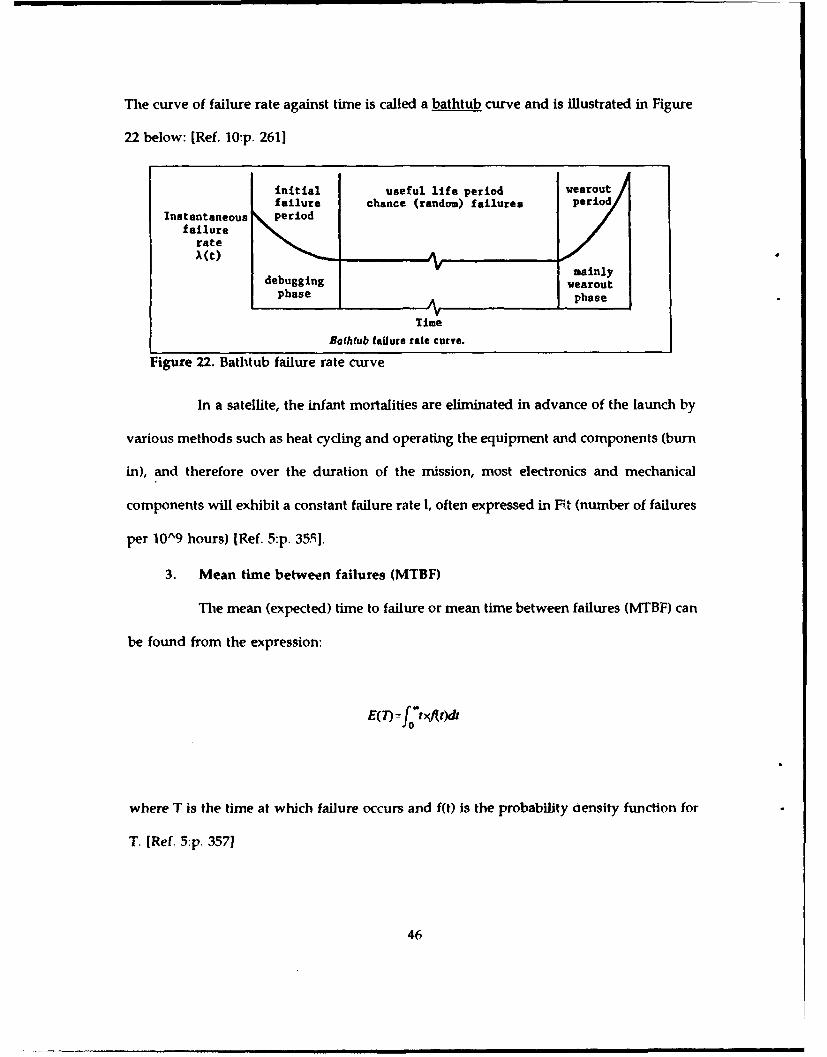
The curve of failure rate against time is called a bathtub curve and is illustrated in Figure
22 below: [Ref. 10:p. 261]
initial useful life period wearoutfailure chance (random) failures period
Instantaneous periofailure
rate
V mainlydebugging wearout
phase phase
Time
Bathtub failure rate curve.
Figure 22. Bathtub failure rate curve
In a satellite, the infant mortalities are eliminated in advance of the launch by
various methods such as heat cycling and operating the equipment and components (burn
in), and therefore over the duration of the mission, most electronics and mechanical
components will exhibit a constant failure rate 1, often expressed in Fit (number of failures
per 10^9 hours) [Ref. 5:p. 35.9].
3. Mean time between failures (MTBF)
The mean (expected) time to failure or mean time between failures (MTBF) can
be found from the expression:
0()- fl×t)dt
where T is the time at which failure occurs and ft) is the probability ensity function for
T. [Ref. 5:p. 357]
46
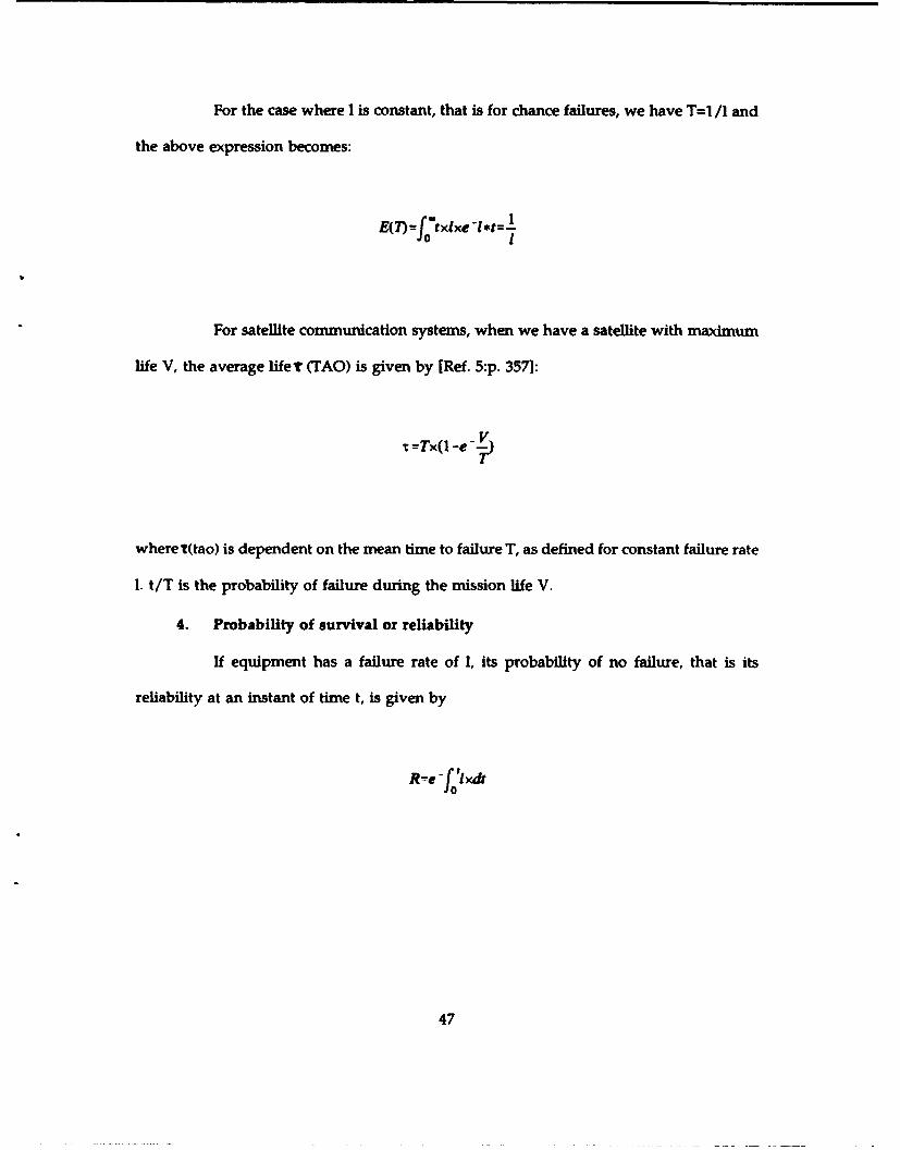
For the case where I is constant, that is for chance failures, we have T=1 /1 and
the above expression becomes:
E(7)=f txlxe -l*t=
For satellite communication systems, when we have a satellite with maximum
life V, the average lifet (TAO) is given by [Ref. 5:p. 357]:
r=Tx( V -e ---
where t(tao) is dependent on the mean time to failure T, as defined for constant failure rate
I. t/T is the probability of failure during the mission life V.
4. Probability of survival or reliability
If equipment has a failure rate of 1, its probability of no failure, that is its
reliability at an instant of time t, is given by
R-e -f'xdt
47

When the failure rate is constant the above expression becomes [Ref. 5:p. 356]
R=e -Ixt
5. Mission Reliability
To ensure service which is defined by a given availability A during a fixed
period L, we must plan the number n of satellites to be launched during the system
lifetime L. The required number of satellites n and the system's availability A will be
evaluated in two typical cases in which the time required to replace a satellite in orbit is
Tr and the probability of launch success is p [Ref. 5:p. 3581.
a. Without spare satellite in orbit
* Required number of satellites: As the average life of a satellite is t(tao), during L years,on average S=L/t satellites have to be placed in orbit and n=S/p launches must beattempted.
" System availability: The system unavailability is given by B=Tr/p'T and the system'savailability is given by A=I-(Tr/p*T)
b. With a back-up satellite (in orbit)
If a back-up satellite has a failure rate I and a life V equal to an active
satellite, it would be necessary to launch n times and the system availability is A as
follows:
2LpxTx(l-e- V A=--(2Tr2)p2xT2
48
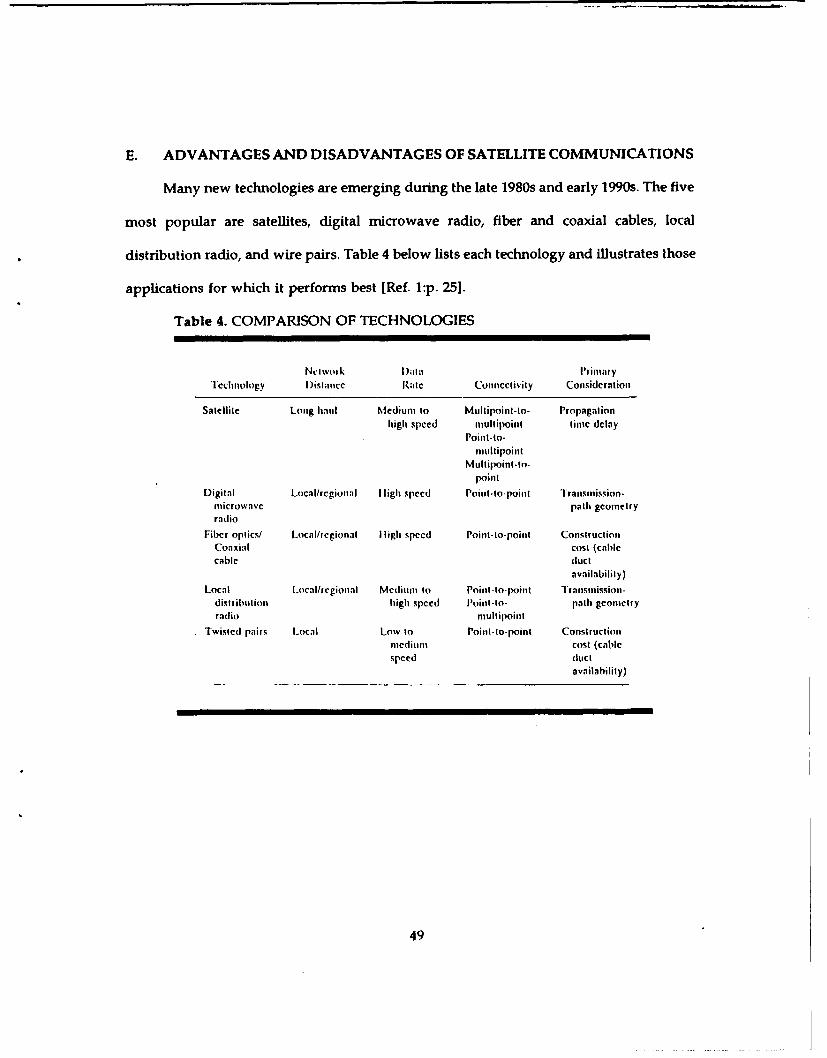
E. ADVANTAGES AND DISADVANTAGES OF SATELLITE COMMUNICATIONS
Many new technologies are emerging during the late 1980s and early 1990s. The five
most popular are satellites, digital midcrowave radio, fiber and coaxial cables, local
distribution radio, and wire pairs. Table 4 below lists each technology and illustrates those
applications for which it performs best [Ref. 1:p. 251.
Table 4. COMPARISON OF TECHNOLOGIES
NcIoI lk I )in a lriM~iYlFcclinology lDgstancc Rate Conn1cctivity Consideration
Satellite Long hauil Medium to Multipoint-to- Propagationhigh speed mnultipoint tinmc delay
Poinlt-to-inulti;,oinit
Multipoint - o-Point1
Digital LocalI/regionalI I ligh speed Poiiit -to-poillt Transmission-microwave path geomectryradio
Fiber optics/ Local/regional I I gh speed Point-to-point ConitructioulCoaxial cost (cablecable duct
availability)
Local Local/regional Medium to I'oint -to-poinit I ransinission-distributfionl high speed l'oint-to- Path geonictryradio mult ipoint
Twisted pairs Local Low to Point-to-point Constructionlmediumn cost (Cablespeed duct
availability)
49

In general the advantages and disadvantages of communications satellites are:
[Ref. 9:p. 10]:
1. Advantages
" Wideband capability.
" Wide area coverage readily possible.
* Distance-insensitive costs.
" Counterinflationary cost history.
" All users have the same access possibilities.
" Point to point, point to multipoint (broadcast), and multipoint to point(datacollection) are all possible.
" Inherently suited for mobile applications.
" Readily compatible with new technology.
" Capabilities sometimes greater than immediate needs.
" New and fresh concepts and opportunities.
" Services directly to the users' premises.
2. Disadvantages
" High initial investment in space segment normally required.
" New investment may be required in earth stations.
* Short satellite Mw-etimes (7-10 years).
" Orbit/spectrum crowding, frequency sharing, power flux density limits.
" Access to end user may be difficult for engineering or regulatory reasons.
" Institutional/legal/regulatory aspects.
" Possibly difficult or expensive maintenance.
50

III. MILITARY SATELLITE COMMUNICATIONS
A. BACKGROUND
When the concept of using satellites for communication purposes became a
possibility, the military soon realized that satellites could play an important role in military
communications as well. In particular, they could interconn.ect widely dispersed forces
around the world to their strategic headquarters (both during peace time and in tactical
battle field situations) and as a means of quickly and reliably transferring information on
military intelligence.
While civil communications satellites could also, to some extent, be used for these
purposes, it was felt that the military requirements for secure communications, free of
interception and/or jamming, radiation hardening of the satellites themselves, etc.,
guaranteed the development of dedicated satellites for the military. Several countries have
therefore developed such systems for this purpose.
B. DEVELOPMENT OF US MILITARY COMMUNICATION SATELLITE
PROGRAMS
The US military role in space communications may be considered to have begun on
December 18, 1958 when the US Army launched the upper stage of an Atlas B missile into
orbit after loading it with an active repeater communications payload. This satellite was
called SCORE and operated for twelve days before its batteries failed. Only a few hours
of communications experiments took place due to the limited time it was visible from
ground stations. [Ref. ll:p. 641
51
The second US military experiment in space communications was on October 4,1960
when US Army successfully launched its first real active repeater satellite, the COURIER
1-B. This was the back up of COURIER 1-A which failed due to an explosion of its Thor-
Able Star launcher. COURIER 1-B was used for a number of real-time and store-and
forward communication experiments until, seventeen days after its launch, a failure in its
command system put it out of operation permanently. [Ref. 11:p. 64]
Following the COURIER program, a number of experiments were carried out by and
for the military using the LES (Lincoln Experimental Satellite) series, developed by the
Lincoln Laboratory of MIT. This program started with the launch of LES-1 on February
1965 and ended on March 1975 with the launch of LES-8 and LES-9. LES-8 and LES-9 are
the latest in the Lincoln Lab series and are the first of their satellites to employ:
" Three axis stabilization.
" Radioisotope Thermoelectric Generators (RTG's) instead of solar cell arrays.
• Ka-band payloads whose antennas can be oriented for use either for space-to-groundlinks or for inter-satellite cross links between the two.
" Pulsed-plasma thrusters for station 1,eping.
After all the experimental programs described above, there was a relatively long time
before the US military launched any further communications satellites. In 1960, ARPA'
initiated the ADVENT project, to develop an advanced military geosynchronous satellite.
However, the program proved to be too advanced for the state of art at that time, so it was
finally canceled in 1962. With the cancellation of ADVENT, another less ambitious project
'ARPA=Advanced Research Projects Agency
52

was started by SAMSO5, which was called Initial Defense Communication Satellite
Program (IDCSP) and was intended to be convertible to a global operational system.
[Ref. 12:p. 150]
1. IDCSP (Initial Defense Communication Satellite Program)
At first the idea was to develop a satellite which could be launched, several at
a time, into polar orbits of about 8000 Kir altitude using an Atlas-Agena launcher. The
progress in the concurrent development of the Titan 3C allowed a redirection of the
original program, to a system to be deployed into near-geosynchronous orbits. The IDCSP
satellites were designed by Philco-Ford with a spin-stabilized configuration which would
need neither active attitude control nor any station keeping. In order to inactivate the on-
board transmitters, a timing device was included which would shut down the satellite
about 6 years after its launch.
The satellite had a 91 cm diameter, 81 cm high polyhedron with each of its 24
faces covered with solar cells. Protruding from one end was the toroidal beam
communications antenna, while a foreshortened telemetry antenna occupied the opposite
end. A cold gas nitrogen jet system was used to spin up the satellite initially, after which
the altitude of the satellite was maintained only passively due to its gyroscopic stability.
The communications payload consisted of a single simple 20 MHz bandwidth repeater,
with the only major element of redundancy being provided by two different TWTA's, one
being switched on only when on-board logic detected a failure of the other[Ref.12 p.1501.
In June 1966, the first seven IDCSP satellites were launched together with a
similar experimental gravity gradient stabilization satellite.
'SAMSO=Space And Missile Systems Organization
53

A second set of eight satellites was launched unsuccessfully in August 1966.
During 1967 and 1968 nineteen more satellites were launched making a total of twenty-six
which exceeded the design goal for their lifetime considerably.
2. DSCS II (Defense Satellite Communication System, Phase II)
The DSCS II satellites followed the IDCSP satellites. The US military decided
in June 1968, after two years of experiments with IDCSP, to develop the Phase II system
which would consist of much more sophisticated satellites in geostationary orbit.
TRW was selected to develop the new satellites under a project called 777. Their
design was a dual spin configuration, with a large rotating drum shaped structure covered
with solar cells, surmounted by a platform that could be dispun to maintain its antennas
facing earthward. The satellite was more than 2.7m in diameter and nearly 4m high. Full
telecommand capability with an automatic attitude control tem and capability to
perform full station keeping was included in the design. The payload consisted of a broad-
band four channel repeater incorporating extensive redundancy. Two horn and two
repointable reflector antennas provided both global and spot beam coverage. [Ref.12 p.151]
The satellites were planned to be launched two at a time by any of the TITAN
launcher configurations. In total, sixteen DSCS II satellites were launched in several
successive orders starting in November 1971. Some of the satellites failed because of
various problems which led to their destruction or loss of service, but the program was
generally successful in providing for the military's long distance strategic communication
needs.
3. DSCS III
In 1975, the military issued requests for proposals for their third generation
satellite system, DSCS III. Hughes and General Electric started parallel design studies to
54

define the configuration of a much higher performance satellite than those of DSCS II.
Now, the requirements were specifically for a three axis stabilized satellite, using a number
of anti-jamming techniques, including the use of antennas with narrow spot beams for
transmission, and receive antennas that could electronically avoid the hostile jamming
stations. In addition, spread spectrum multiple access techniques were to be incorporated
with a frequency hopping capability as another protection against hostile interference.
Finally, G.E was awarded the contract for the development of the DSCS III satellites in
February 1977. The initial contract for one qualification and two flight demonstration
satellites was worth more than $75 million. [Ref. 12:p. 152]
The communication system on this third generation satellite is the most
advanced of its type, particularly with regard to its antennas. For reception, there are two
earth coverage horns and one multibeam (61 beams) waveguide lens array antenna
operating at X-band and a crossed bowtie antenna operating at UHF. For transmission,
there are two earth coverage horns, two 19 beam waveguide lens arrays and one
deployable gimballed parabolic antenna at X-band, and a crossed dipole UHF antenna. The
satellite measures some 2.4m in diameter and 2m high, has two deployable panel solar
array wings, and uses four inertial wheels for stabilization on station. [Ref-li p.152]
The program was delayed until October 1982 when the first demonstration
satellite was launched together with the FM16 (Flight Model #16) of DSCS II satellites.
Although the plan was for 12 production satellites to be ordered after the successful in
orbit testing of the demonstration models, only 7 have so far been reported to have been
contracted for. The first two of these were launched in October 1985, using the Space
Shuttle. [Ref. 11:p. 1521
55

4. Tactical Satellites (TACSAT)
The satellites of the IDCSP and DSCS series were intended primarily for
strategic, high data rate military communications, using a small number of earth terminals,
each having large diameter antennas. However, there is a need for tactical communications
amongst field units and between field units and their tactical headquarters, where the use
of such large antennas is not generally feasible. In order to develop the capability and
ground equipment for multiple access satellite communications between mobile terminals
numbering in hundreds and in order to determine the best frequencies for future
operational tactical communications services, TACSAT was conceived. The contract to
develop TACSAT was awarded to Hughes Aircraft Company (HAC) in late 1960's.
[Ref. 3 :p. 2361
TACSAT's design requirements cuctated a number of features not present in
previous communication satellites. Since there was virtually no interest in tactical
communications in the commercial field, engineers who worked on TACSAT were
frequently treading on new ground. Its beginning-of-life mass in geostationary orbit of 1600
lbs made it the heaviest communication satellite of its time, and its overall dimensions
(2.8m in diameter and 7.6m high) made it the largest. [Ref. 13:p. 236]
It was spin stabilized but because of its large antenna structure and launch
vehicle fairing constraints, it did not spin about the axis having the maximum amount of
inertia. In order to overcome this unstable condition, special stabilizing elements were
employed.
With a total radiated RF power of 260w, TACSAT was also the most powerful
communication satellite of its time. It had a total of sixteen solid-state UHF power
amplifiers, any thirteen of which were generally operated at a time, to provide a total of
56
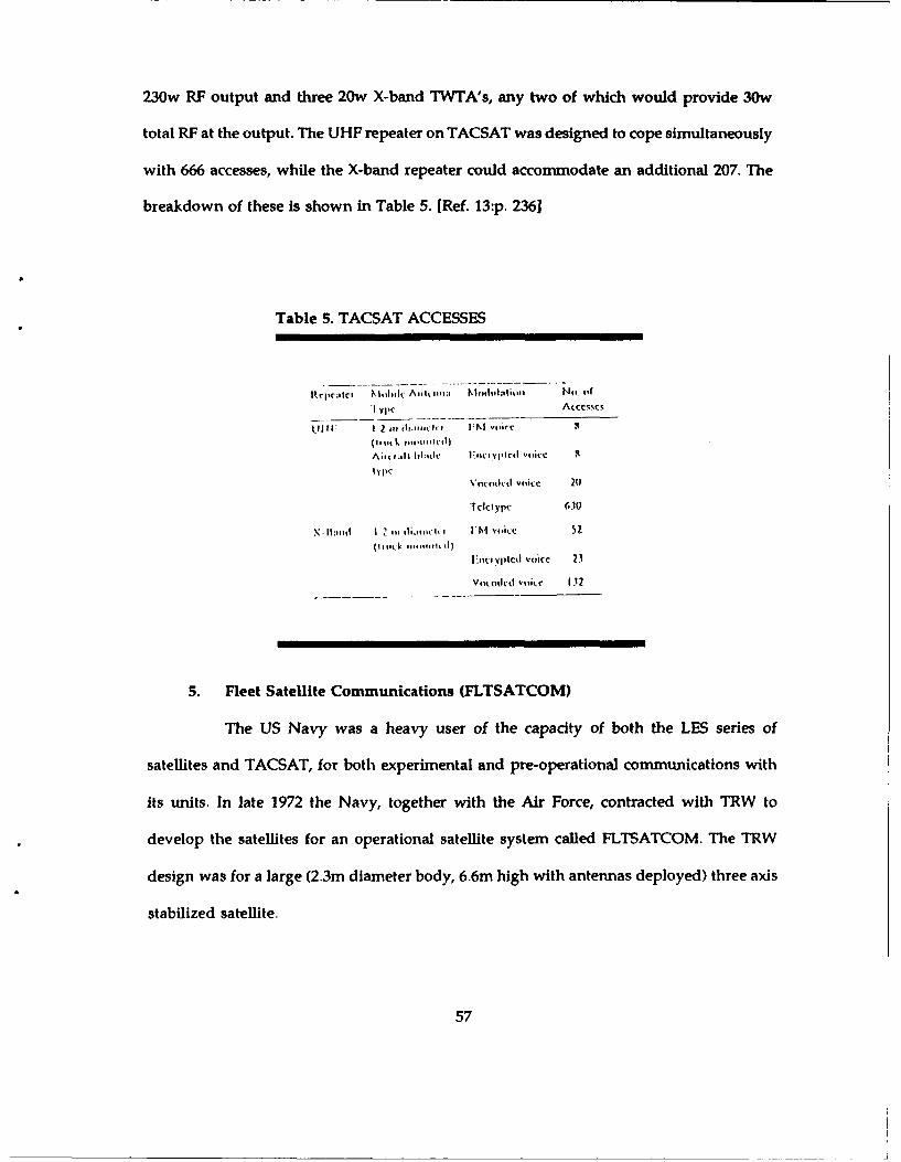
230w RF output and three 20w X-band TWTA's, any two of which would provide 30w
total RF at the output. The UHF repeater on TACSAT was designed to cope simultaneously
with 666 accesses, while the X-band repeater could accommodate an additional 207. The
breakdown of these is shown in Table 5. [Ref. 13 :p. 236]
Table 5. TACSAT ACCESSES
Rcp.c:,t ',.k"i~ A. , lh thi.t 40,g Nil. ofr
1l~l 2 it dlia"It'h't iM vtcr"
-I'pc(1'%'(k ,,.simicil)
Voco 'ctl voice 20
Tdcoypt: 63(
I"..wVp1lcd vticc 23
Vq)q:(1OCf vdi:c 132
5. Fleet Satellite Communications (FLTSATCOM)
The US Navy was a heavy user of the capacity of both the LES series of
satellites and TACSAT, for both experimental and pre-operational communications with
its units. In late 1972 the Navy, together with the Air Force, contracted with TRW to
develop the satellites for an operational satellite system called FLTSATCOM. The TRW
design was for a large (2.3m diameter body, 6.6m high with antennas deployed) three axis
stabilized satellite.
57
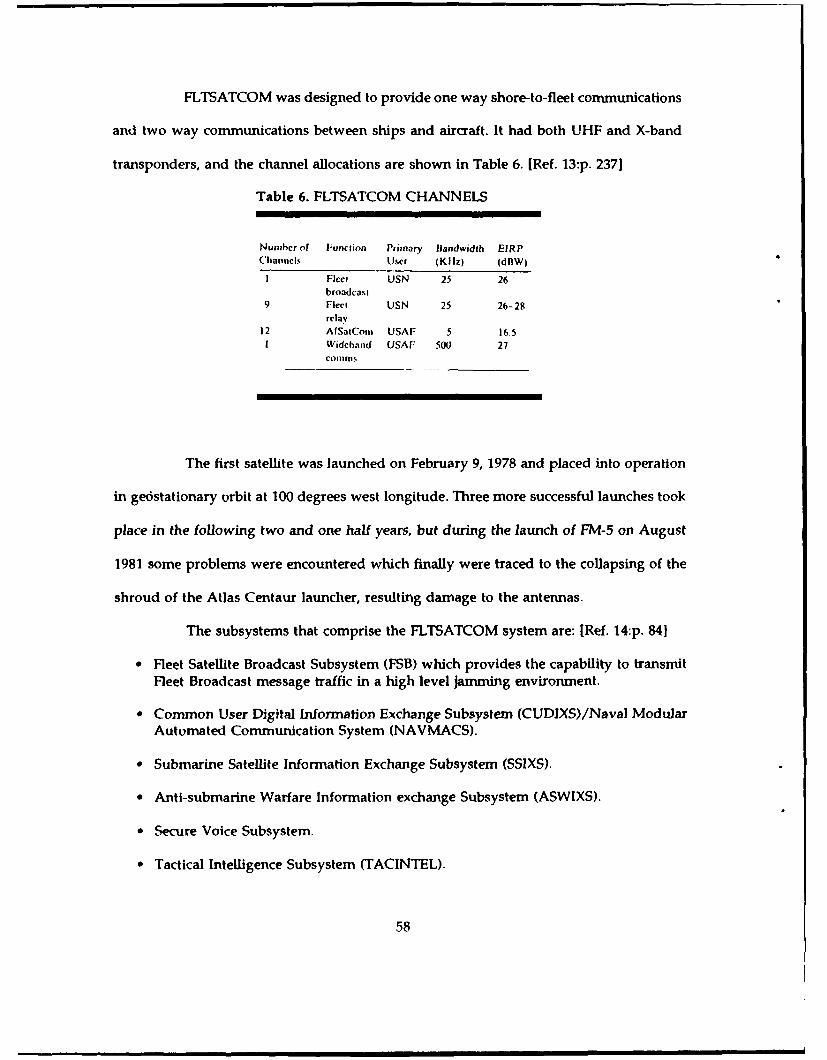
FLTSATCOM was designed to provide one way shore-to-fleet communications
and two way communications between ships and aircraft. It had both UHF and X-band
transponders, and the channel allocations are shown in Table 6. [Ref. 13:p. 237]
Table 6. FLTSATCOM CHANNELS
Number of Function Primary landwidth EIRPChanncls User (KIIz) (dBW)
I Fleet USN 25 26broadcast
9 Fleet USN 25 26-28relay
12 AfSatCom USAF 5 16.51 Widcband USAF 500 27
COlilnis.
The first satellite was launched on February 9, 1978 and placed into operation
in geostationary orbit at 100 degrees west longitude. Three more successful launches took
place in the following two and one half years, but during the launch of FM-5 on August
1981 some problems were encountered which finally were traced to the collapsing of the
shroud of the Atlas Centaur launcher, resulting damage to the antennas.
The subsystems that comprise the FLTSATCOM system are: [Ref. 14:p. 841
" Fleet Satellite Broadcast Subsystem (FSB) which provides the capability to transmitFleet Broadcast message traffic in a high level jamming environment.
• Common User Digital Information Exchange Subsystem (CUDIXS)/Naval ModularAutomated Communication System (NAVMACS).
" Submarine Satellite Information Exchange Subsystem (SSIXS).
" Anti-submarine Warfare Information exchange Subsystem (ASWIXS).
* Secure Voice Subsystem.
" Tactical Intelligence Subsystem (TACINTEL).
58
6. LEASAT Satellite
The last generation of communication satellites for Navy use has been obtained
on a leased basis, hence the program name, LEASAT. When the Navy initiated a
procurement action for its next generation of satellites to replace FLTSATCOM, its request
for proposals called for the lease of communications services, rather than for the
development and purchase of satellites. The contract was awarded to HAC which proposed
to build five LEASAT satellites to provide communications from four orbital locations (the
fifth was a spare on ground). The LEASAT design was unique in that it was the first
communication satellite designed specifically to be launched only by the Space Shuttle.
LEASAT is 4.22m in diameter and 4.30m long when mounted in the Shuttle. It has an
integral solid motor perigee stage, and two liquid bi-propellant apogee engines.
The payload includes two large deployable helical antennas, and 12 fully solid-
state UHF repeaters. It has seven 25 KHz UHF downlink channels, one 500 KHz wideband
channel and five 5 KHz channels. One of the seven 25 KHz UHF downlink channels is the
downlink for Fleet Satellite Broadcast (FSB) message traffic. The broadcast uplink is SHF
with translation to UHF occurring in the satellite. [Ref. 14:p. 89]
The first LEASAT was launched in August, 1984 and the second in November
of the same year. In April, 1985 LEASAT-3 was launched but it was inoperable due to a
failure of one on-board timer until the end of 1985, when it was fixed during the launch
of the LEASAT-4 in August 1985.
59

C. ADVANTAGES/DISADVANTAGES
The satellite communication systems have already and will continue to provide
effective solutions to many of the problems. inherent in Military operations. Some of the
advantages and disadvantages of the current communication satellite systems are:
1. Advantages
" Satellites are able to provide connectivity to and from geographically remote areaswith few support facilities which may be subject to enemy hostile actions.
" In a case of political instability, satellite communications allow independence onoverseas communication sites.
" Satellite communications connect widely separated members in the chain ofcommand, rapidly and reliably passing information.
" Satellite communication systems can reduce the Frobability of position intercept andincrease resistance to jamming.
2. Disadvantages
* Cost constraints led to decisions based on space segment cost only and producedintegrated, multi-function spacecraft which could become single-point targets forattempts at destruction or jamming by the enemy.
" Limitations on operation in the UHF band are due to frequency congestion, lack ofbandwidth, and inadequate jamming resistance.
" Heavy rainfall can cause high propagation losses at EHF.
60

IV. INTERNATIONAL SATELLITE COMMUNICATIONS: INMARSAT
A. INTRODUCTION
In 1956, the first intercontinental telephone cable came into service. It substituted for
the few HF radio circuits on which international telephony was dependent. This
Transatlantic Telephone cable (TAT 1) had an initial capacity of thirty-six circuits, which
was thought to be enough to carry all the transatlantic traffic for some years ahead. But
the demand for calls increased very rapidly when users discovered the importance of
telephone service. TAT 1 was followed by a succession of transoceanic cables of ever-
increasing capacity. However, shortages in intercontinental circuits were frequent during
the 1960's and 1970's.
When trials with INTELSAT-1 concluded that the delay via a satellite was not a large
disadvantage for the majority of the users, the satellite was quickly pressed into
commercial use.
Although communication satellites were first to provide a complementary service to
long-distance cables, there are important differences between the two means of
transmission. These include: [Ref. 8:p. 7]
* Cables are best suited to the provision of point-to-point circuits whereas themultiple-access property of satellite systems means that they can provide point-to-multipoint service or multipoint-to multipoint service.
* The cost of cable circuits increases with their length whereas the cost of satellitecircuits is independent of the distance between earth stations.
9 Satellite transmission can leap over physical and political barriers that are impassableto cables.
* Satellites can provide service to mobile stations.
61

1. Intelsat (International Telecommunication Satellite Consortium)
On August 20, 1964, after some two years of discussions and negotiations,
eleven countries signed an agreement bringing into existence an Interim "International
Telecommunications Satellite Consortium". The consortium would own and operate, on
behalf of its signatories, satellites to provide international communications services. A brief
description of the Intelsat series satellites is provided below: [Ref. 15:pp. 269-2771
a. Intelsat-1
Less than a year after the agreement was signed (1965), the first satellite,
Intelsat-1, manufactured by Hughes Aircraft Company, was launched and began to provide
trans-Atlantic service. Its capacity was 240 simultaneous telephone channels or one
television channel. Despite having an intended design life of only 18 months, Intelsat-1
continued to provide service continuously for almost four years. It was placed in a reserve
mode in January, 1969.
b. Intelsat-2
Intelsat-2, also built by Hughes, was similar in design and channel capacity
to lntelsat-1. Its first launch was unsuccessful (October 1966) due to a failure of its apogee
kick motor. The second flight model was successfully launched and placed into orbit in
January 1967. It provided communications capacity in the Pacific Ocean region until
February 1969. The third flight model was launched in March 1967 and placed into service
in the Atlantic Ocean region, where it operated continuously until January 1970. It was
then operated as a spare until its transponder failed in December 1970. In September 1967,
flight model four was launched and provided service in the Pacific Ocean region, with
some interruptions, until it was terminated September 1971.
62
c. Intelsat-3
The contract to provide the third generation of Intelsat satellites, Intelsat-3,
was won by TRW Corporation. It carried dual repeaters with a combined capacity of 1200
telephone circuits. A total of eight Intelsat-3 flight models were procured. Three of these
failed to reach geostationary orbit (#1,5,8). Flight model #2 was launched in December 1 i68
and placed into service in the Atlantic Ocean region. It soon experienced problems, which
were corrected for a time, but it finally failed completely in April 1970. Flight model #3
was launched in February 1969. However shortly after its launch it experienced problems
that reduced its capacity. It was moved from its Pacific Ocean position to the Indian Ocean
and it was operated with only occasional outages until it was put in a reserve status in July
1972. In May 1969 flight model #4 was launched and positioned over the Pacific. When it
began operation in July 1969, Intelsat was, able to provide global service to its users for the
first time. Flight models #6 and #7, which were launched in 1970, each experienced
problems. Thus, they were retired as soon as the satellites of the Intelsat-4 generation
became available to take over their functions.
d. Intelsat-4
Even before the first Intelsat-3 satellite was launched, it became apparent
that the growth in traffic demand would soon make even larger satellites necessary.
Hughes Aircraft Corporation (HAC) won the competition to supply these, with a design
based upon the successful TACSAT military satellite. With capacity improvement from
using twelve separate channelized repeaters, a theoretical capacity of up to 9000
simultaneous telephone circuits was possible, depending upon the traffic pattern and
modulation schemes used. A total of eight Intelsat-4 satellites were procured. All the flight
63

models except Flight model #6 were launched and placed in orbit successfully, between
1971 and 1976 making this series of satellites highly successful on the whole.
e. Intelsat-4A
Although Intelsat-4 had more than five times the capacity of Intelsat-3, it
soon proved to be insufficient to cope with the demand for international satellite
communications. Because of the success of the Intelsat-4 series, Intelsat elected to procure
a growth version of its design from Hughes, designated 4A, rather than to open a new
competition for a next generation satellite. Intelsat-4A obtained the necessary increase in
capacity by expanding the payload from 12 to 20 repeaters, and by increasing from 2 to
3 spot beam antennas. The corresponding maximum capacity of this configuration was
some 15000 telephone circuits. A total of six Intelsat-4A satellites were procured, the first
of which was launched in September 1975. All remaining flight units were launched over
the next 2.5 years, with the exception of Flight model #5. This satellite had a launch failure
in September 1977. This series formed a new global network in the three ocean regions
served by Intelsat.
f . Intelsat-5
Intelsat-5 was a major departure from its predecessors. It was three axis
stabilized,while all previous satellites in the Intelsat series were spin or dual spin stabilized.
It was also the first dual band Intelsat satellite, using an allocated 500 MHz in 21
transponders operating at C-band, and another 500 MHz in 6 transponders at Ku-band. Its
capacity was 12,000 voice circuits and two television channels. The first of nine Intelsat-5
satellites to be launched experienced several anomalies shortly after its launch. Three of
these were considered significant enough to require design changes in later models.
However, the problems didn't stop when these changes were made. Further anomalies
64
were encountered in later flight models. Nevertheless, while these problems sometimes
reduce the quality of the transmissions through these satellites, they are still usable.
g. Intelsat-5A
In 1980, Intelsat satellites were carrying some two-thirds of the world's
international overseas telephone traffic, and the amount of this traffic was growing at a
rate of nearly 25% per year. Thus, even before the first Intelsat-5 was launched, it was
realized that satellites with even greater capacity would soon be required to keep up with
the growth. The overall telephone traffic capacity was increased to 16000 two way circuits
by Intelsat-5A satellites.
h. Intelsat-6
Planning for international communications is a long-term business, and the
planning for the post-Intelsat-5 era commenced in 1975 with long-range forecasts of traffic
and service requirements in the three ocean regions. A large number of different system
configurations were analyzed, and work on specification of the Intelsat-6 satellite
commenced in 1979. The 1982 price for the initial five satellites was about $525 million. It
was intended that the first Intelsat-6 should be brought into operation in the Atlaniic
Ocean Region in 1987, but shortages of launch vehicles resulting from problems with the
Shuttle and Ariane programs postponed this until late 1989. Each Intelsat-6 satellite is able
to carry over 30000 telephone circuits and four television transmissions. To date, flight
models #1 and #3 were launched successfully on November 2, 1989 and June 23, 1990,
respectively. Flight model #2 failed to reach geostationary orbit on March 14, 1990.
According to design specifications, Intelsat-6 promises to be a successful
series of telecommunication satellites, but we have to wait for results in the very near
future. [Ref. 8 :p. 221
65

i. Intelsat-7
Intelsat's present plans are to specify a satellite which is primarily geared
to the requirements of the Pacific Ocean region, but can easily be adapted to the Atlantic
Ocean region, where the traffic is growing very fast. The communication package will
probably be similar to Intelsat-5 and Intelsat-6, but with a smaller bandwidth. The first
Intelsat-7 series satellite will be launched in 1993 at the earliest. [Ref. 8:p. 22]
2. Eutelsat (European Telecommunications Satellite Organization)
Eutelsat is a regional system which provides communications between a group
of countries with common interests. It offers a way of spreading the very large investment
required to establish a satellite system in the area of Europe. The services which are offered
by Eutelsat are: [Ref. 3:p. 31]
* It channels a significant portion of intra-European public telephone traffic.
* It leases portions of the space segment for the distribution of television programs.
" It provides multi-service transmissions tailored to the specific needs of the businesscommunity.
* It provides for the transmission of Eurovision television programs.
The great success of the Eutelsat I satellites, in 1983-1984, led the way for the
second generatior of Eutelsat satellites. The first flight unit of this generation was launched
in mid-1989. Eutelsat has an option for two additional units. [Ref. 3:p. 31]
B. INMARSAT
1. Background
By resolution A.305 (VIII) of 23 November 1973, the Assembly of the Inter-
Governmental Maritime Consultative Organization (IMCO) decided to convene an
66

international conference to set up an international maritime satellite system and to
conclude agreements to implement this decision. [Ref. 16:p. 2151
The commercial maritime satellite communications service was first provided
by the MARISAT system, which was established in 1976 by four major communications
entities of the U.S. This system was originally intended for U.S. domestic communications,
but the service is open to vessels of other countries, too. Today MARISAT satellites are
positioned one each over the Atlantic, the Pacific and the Indian Oceans. [Ref. 18:p. 334]
The European Space Agency's MARECS program covers the development,
launch and in-orbit operation of communication satellites to be integrated in global
maritime communication system. The MARECS satellite is part of a global communications
system configured to provide high quality full-duplex, reliable real-time voice, data, and
teleprinter services between SES and CES with automatic connections to the terrestrial
network. [Ref. 18:p. 336]
a. The Establishment of INMARSAT
Pursuant to this decision, the International Conference on the
Establishment of an International Maritime Satellite System was convened in London on
23 April, 1975 for its first session. The conference concluded its work at its third session
on 3 September 1976. The following were adopted by the conference:
- Convention on the International Maritime Satellite Organization (INMARSAT).
- Operating agreement on the International Maritime Satellite Organization(INMARSAT).
Both agreements entered into force on 16 July 1979, 60 days after the date
on which states representing 95% of the initial investment shares had become parties to
them. The Organization's headquarters are in London.
67

b. Purpose
The main purpose of INMARSAT is to make provisions for the space
segment to improve maritime communications, thereby improving communications
concerning distress and safety of life at sea, efficiency and management of ships, maritime
public correspondence services, and radio determination capabilities. The organization
seeks to serve all areas where there is need for maritime communication and acts
exclusively for peaceful purposes. [Ref. 8:p. 2381
c. Organization
INMARSAT has three main organs:
" The Assembly, where all member states are represented and have one vote each.
" The Council, which has 22 signatories and voting power in relation to investmentshares.
" The Directorate, headed by a director-general.
Substantive decisions are taken with a two-thirds majority, both in the
Assembly and in the Council. The functions of the Assembly are to consider and review
the general -oicy and lay term objectives of the Organization, express views, and make
recommendations thereon to the Council. All other decisions are taken by the Council. So
the Council decides on all financial, operational, technical, and administrative questions.
2. Facts about INMARSAT
INMARSAT is an internationally-owned cooperative which provides mobile
communications worldwide. From its establishment, it has evolved to become the only
provider of global mobile satellite communications for commercial and distress and safety
applications at sea, in the air, and on land.
68

Thirty-two states had become parties to the INMARSAT convention by 1980,
and by June 1990 INMARSAT had 59 member countries. The services that the INMARSAT
can now support include: [Ref. 17:pp. 1-4]
a. Maritime applications
" Direct dial telephone.
" Telex.
* Facsimile.
* Electronic mail and data connections for maritime applications.
b. Aircraft applications
" Flight-deck voice and data.
* Automatic position and status reporting.
" Direct-dial passenger telephone.
c. Land applications
" Two way data communications.
" Position reporting.
" Electronic mail.
" Fleet management.
Current maritime users of the system include oil tankers, liquid natural gas
carriers, offshore drilling rigs, seismic survey ships, fishing boats, cargo and container
vessels, passenger liners, ice breakers, tugs, cable-laying ships and luxury yachts, among
others. The system is also used on land and in the air for several applications, including
the provision of commercial, emergency transportable communications at times of human
disaster and natural catastrophe. (Ref. 17 :pp. 1-4]
69
In 1990, INMARSAT introduced aeronautical services that will provide
worldwide aeronautical passenger telephone, facsimile and data services, as well as
improve airline operations and air traffic control. Many airlines and corporate aircraft are
now being equipped to use these services.
INMARSAT is also introducing a new range of two-way data messaging
services which will use low-cost mobile terminals called INMARSAT-C. These terminals
are small enough to fit on any boat or vehicle or to be hand carried. These services are
being adapted for both maritime and land mobile users. They will be used for a wide
variety of applications, including general telex and electronic mail communications,
information distribution from one ship or vehicle to a group of specified users, remote
monitoring and control, position reporting, and fleet management. [Ref. 17:pp. 1-41
As of June 1990, more than 11000 user terminals have been commissioned on
land, sea, and in the air for use with the INMARSAT system.
INMARSAT is also exploring the possibility of using satellites for position
determination and navigation applications. In 1992, INMARSAT plans to introduce a
briefcase-sized worldwide mobile telephone service. [Ref. 17:p. 1]
3. The satellite system
In January 1980 a request for proposals for the procurement of the space
segment was issued, with commendable speed. In May 1980 INMARSAT received offers
to lease satellites from MARISAT and the European Space Agency (ESA), and an offer from
INTELSAT to lease maritime communications subsystems (MCSs), which would be added
to Intelsat-5 satellites. (Ref.8:p. 2391
It did not make sense to have two competing maritime communications satellite
systems, so the INMARSAT started by taking over the MARISAT satellites. However,
7n

additional satellites were required, both as spares and to replace MARISAT due to its
limited capacity and life. So INMARSAT leased three MARISAT satellites and provided
for the future by ordering two MARECS satellites (frovi ESA) and taking an option for up
to four MCSs. The current configuration of the system is shown in Table 7. [Ref. 17:p. 41
Table 7. THE SATELLITE SYSTEM
Ocean LaunchRegion Spacecraft Date Status
Atlantic (AOR) Mareco-B2 9 November 1984 OperationalIntelsat V-MCS B 19 May 1983 Opertlonal*Marisat-FI 19 Pebruary 1976 Spat
India (IOR) Intelsat V-MCS A 28 September 1982 OpertionalImisiat-P2 14 October 1976 Spare
Pacific (POR) Intelsat V-MCS D4 March 1984 OperationalMamec-A 20 December 1981 Operatlonal*Marizat-F3 9 imne 1976 Spare
0 Ilmastat operates two satellites in its Atlantic mnd Pacific Ocean Regions(s from September 1989)
71

As we can see INMARSAT now has satellites in its three ocean regions capable of
providing two-way communications services to its users.
Figure 23 shows INMARSAT's coverage area. [Ref. 8:p. 2531
200 220 240 26.0 2!0 300 3201 340 0 20 40 60 1060 2 10 IS
0 -
0
60
0
200 20 240 260 2;0 300 320 340 0 204 60S 1010 0IO10
2!1Ocean Region Code (Telex) ocean Region Code (Telephone)
Figure 23. INMIARSAT's coverage area
72

Table 8 shows the main parameters of the INMARSAT system. [Ref. 5:p. 121
Table 8. INMARSAT's MAIN PARAMETERS
S/C nome(iJ NIARISA r MARKS INIELSAT-3-MCS"
I'lune conliaclov litighir Aliciall lhleiihl Ato'Pace rFord ActnipactLitunch dates t9 1e1'ruaw, 1976; 9 A! 20) Decembetir 1961 zo 23Setierber 1932
June 1976: 14 Octobver It: 9 N,conher 1984 F6: 19 May 19331916 Fl: Ill Octobet 1933
r+: 4 Match 19R4Launicher(s) Oitds 2914 Atiane Ais Centaur and
AtioneLaunch site EIR. r'lorida c.so. xcoutoi. riench IElK end CSO
9linaDesign file (yrq) 3 77Orbital posilion, i3'W', i176.5'C 71"r 26', i1773,1 63:11; ip.5*W: 6'E:
71anqier orbit
N1a49 Ike) 633 1006 (A); 1014 in) 1110lriniriry powis 1wV) 3,o 111O M30 (EOL)1riqencles 250-400 Miip. is1.11-i42.5 fi z 1333-t342.5 Milt
1517--341 Mliii 1638 6- 1644.5 kilii 1636.5-1644 MlIIt16315-1642.3 Mliit 4133...-4200.3 Mile 4192.5-4200 Mile4193-4199 N1Iti 6415.9-6425 Mlei 6417.5-6420 MI It6420-6424 Mlti
No. of active I (I ~ItIi: I L-banid: I C 101 2 Ic-i. I 1.-c) ortraniponderi I C-band) I LI OC 7.5 Milt bandwidth
fiachEi~r (dnW) umo (21 dOW-wicle C (iS.? dOW) c-bovnd (70 dOwls
bond*, 73 dltV-notoW L J14.1 411W) L~nd inX duWybond): C (11.3 dow):L (24 d )(Metdirimree nond)
*0ortuni' stations 3 cciii earth stations-. - i3 coast earth Saome stations as lot1u.8 mr? allonw MAilECS- 700 ship let minais! - 2500 ship terminals1.2 MO
Capacity Iu tiII r channels 46 voice channels. iPnch 33 wakce channeis(one wide bvind anid ch.-nvnel can carry 23 totwo narrow havndp, pill, 30 jIea rue.sallesone two *its Valve Cl, Instead of vwokecivil andI 44 Ilee, chan-rel' while UiS wall us-Ing Uiir (due ito povrr
'Thravi to nine Voice
and 11iO tee channelswben Ilavy clised oitor it, wlir chiannels
73
INMARSAT is now in the process of procuring a second generation of satellites.
The INMARSAT-2 spacecraft, the first of which was launched in October 1990, will have
three to four times the capacity of the most powerful satellite in the present INMARSAT
system. INMARSAT has ordered four INMARSAT-2 satellites from British Aerospace, with
options for an additional five. [Ref. 17:p. 21
4. User terminals
Most current users of the present system use Inmarsat-A terminals or their
transportable derivatives. The new Inmarsat-C micro terminal supports the new two-way
data-only communications services.
a. Standard-A terminal
Mainly for larger vessels or those with sophisticated communications
requirements, a standard-A ship earth station (SES) uses INMARSAT satellites to provide
high quality connections into the world's international and national telecommunications
networks. About 30% of the Standard-A SESs in service are on oil tankers and about 70%
are on ships over 10000 tons. [Ref. 8:p. 240]
Standard-A SESs are produced by about a dozen different manufacturers
and marketed through thousands of agents worldwide. The most obvious feature of a
Standard-A SES is its radome, which encloses a parabolic dish antenna, usually of less than
one meter in diameter. The antenna is motorized so that it tracks the satellite precisely,
regardless of ship movement. Each comes equipped with an automatic pushbutton
telephone and a telex machine. Optional equipment is available for many other services
such as facsimile, data transfer, and even television.
74

Standard-A SES can provide the following services: [Ref. 8:p. 241]
* Telephone.
* Telex (50 Baud).
* Facsimile.
" Data transmission (Up to 9600 B/s).
" 'Broadcast' telex or voice messages to groups of ships.
There are three types of Standard-A system SES:
* Class 1 stations, which carry telephone and telex traffic.
" Class 2 stations, which carry telephone traffic only.
" Class 3 stations, which carry telex traffic only.
(1) Above and Below Deck Equipment (ADE and BDE)
The components of a ship's terminal are categorized as above and
below deck equipment. The ADE consists of the antenna and its mounting, the radome,
the high power amplifier and the low noise amplifier. The BDE consists of up and down
converter units, frequency synthesizers, equipment for processing the signals, a display and
control unit, and one or more terminal equipments. [Ref. 8:p. 247]
(2) Tracking and Stabilization
It is not always easy to keep the antenna of a Standard-A SES
pointing at the satellite because of: [Ref. 8:p. 248]
" Roll, pitch, and yaw.
" Changes in ship's course.
* Changes in the bearing and elevation of the satellite relative to the ship's movement.
75

Some common methods of counteracting the above effects are:
* Mount the antenna on a platform which is gyroscopically stabilized by twoflywheels spinning on orthogonal axes (counteracts roll and pitch).
" Connecting the drive of the above platform to the ship's compass (counteracts thechange in ship's course).
* Providing a step-track system (counteracts the effects of satellite's and ship's motion).
(3) SES's antennas
The use of antennas with diameters as small as 0.9 m has been made
possible by the availability, at reasonable cost, of gallium arsenide Low Noise Amplifiers
(LNA) with good performance. The characteristics of a Standard-A SES antenna are shown
in Table 9 and Figure 24: [Ref. 8:p. 249]
Table 9. CHARACTERISTICS OFSTANDARD-A SES ANTENNA
Diagmeler 0-9-1.2 niGainl 21-23 dilI lf-powr bc;nwidh (+) 6-7'
EIRP 36dBWGIT (n 5° clcvation with a clcnr sky) - 4d/K
Figure 24. A Standard-A SESAntenna
b. Standard-C terminal
The Inmarsat-C communication system gives two-way store and forward
telex or data messaging communications via satellite to and from virtually anywhere on
the globe. The terminal is small, simple and robust. The largest versions, with fixed omni
76

directional antennas, weigh only 6 Kg and measure 30 x 22 x 11 cm (excluding the
antenna). Some manufacturers are planning versions that will fit in one hand, a pocket, or
-3 handbag. [Ref. 19:p. 11
Communications via the Inmarsat-C system are data or message based.
This means that anything that can be coded into data bits - any data words, text, language
or alphabet - can be transmitted via Inmarsat-C. It can also handle some forms of graphics.
Communications originated from a mobile terminal are transmitted in data
packets, via satellite, to a coast earth station. At the coast earth station, the packets are
reassembled before being retransmitted to their destination - in the fort that has been
nominated by the sender, that is, telex, data, etc. - via the national or international
telecommunications networks. [Ref. 19:p. 1]
There are three main types of Standard-C SES: [Ref.8 p.260]
" Class 1: which provides the basic functions of ship-to-shore and shore-to-shipmessage transfer.
* Class 2: this type of SES has two alternative mode of operation whish can be selectedby the operator. In the first mode it behaves as a Class 1 terminal but can alsoreceive group-call messages when it is not being used for ordinary traffic. In thesecond mode it can be set to continuous reception of group-call messages.
" Class 3: which is a class 1 terminal with the addition of a second receiver allowing
the continuous reception of group-call messages.
With two manufacturers already listing Inmarsat-C terminals for sale, and
several others in an advanced stage of development, users will soon have a wide range of
equipment from which to choose. The first production model to be type approved by
INMARSAT is being manufactured by the Danish firm Thrane & Thrane, it is already
available. The T & T terminal has a small, fixed, conical antenna which, because of its light
weight and simplicity, can be mounted almost anywhere on a vessel or vehicle. The main
77
electronics unit is about the size of a large book and weighs only a few kilos. The udt
interfaces via an RS232 port to a personal computer for message generation and display.
[Ref. 19:p. 2]
(1) Two-way communications
The Inmarsat-C system is capable of providing communications of
virtually unlimited length, in both directions, between a mobile and a fixed communication
center such as a home or office. These communications take place on a store-and-forward
basis, with the store-and-forward message switch being located at the ground station. The
store-and-forward procedure provides several advantages for Inmarsat-C such as:
[Ref. 19 :p. 21
" Service at the lowest cost.
" Flexibility in the type of messages (telex, electronic mail, switched data).
* Automatic reprocessing of the messages into the correct delivery mode.
(2) FleetNet & SafetyNet
These are two new services which take advantage of the Enhanced
Group Call (EGC) which enables messages to be sent to a number of Inmarsat-C mobiles
simultaneously. SafetyNet provides a reliable method for the distribution of maritime
safety information to specified groups of vessels or to all vessels operating in, or about to
enter, specified areas. FleetNet allows commercial messages such as news bulletins, market
reports, and commercial weather services to be distributed simultaneously to groups of
vessels or vehicles. [Ref. 19:p. 31
5. Coast Earth Stations (CES)
Another component of the INMARSAT system is the Coast Earth Station (CES),
which provides the link between the satellites and national and international
78

telecommunications networks. Coast Earth Stations are generally owned and operated by
the signatories oi the countries in which they are located. The Signatories are organizations
nominated by their countries to invest in, and work with, INMARSAT. As of June 1990,
there were 21 CESs in operation, which are shown in Table 10: [ Ref. 17 :p. 3]
Table 10. COAST EARTH STATIONS IN OPERATION
Cvvex'oge OperatiotnntC0unt1ry Locationi Regiun S(ntus
111ayil Tmigia Atlantic Ocean In oper'ilorEigypt Niandi Alanicl Ocean In operationI',t 1ce -J'lelmnucur ljou Atdandtc Ocean In opef ation11511Y I? 1cli1 Atinwle Ocean 41, operationrKuwaitt UImm- al WIth Atlantic Ocean In ope mtkonPoland Ps it y Atlantic Oc"an In operationI uikry Ala Atlantic Ocean It- operation
lilt, Onritiiy Atlantic Ocean it opetatijoiUSSR Odc&SAM Atlantic Ocean In operation'USA Soutlibury Atlantic Ocean In operai on
N~orway, Swedenr Elk Indian Ocean In operationOtcece lltrmopylie Indian Ocean Ins operationJapan ymnipituclhl Indi an oe an In operationPoland Puary Indian Ocean In operationS4audl Arabia JeddlII Indian Ocean In operationI urkey Alat Indian O-ean In operationiUSSR Wells in1di an (heart In operationJapan 11haraki Pacific Ocean In operaionSingapore Singnpore Pacific Ocean In operaitoUSSR M akhodka mPacific Ocean In operationUSA Santa Paul* Pacific Ocean In operation
79
a. Antenna
The Figure of Merit (G/T) required at the C-band frequencies is specified
as not less than 32 db/K. This requires an antenna with a diameter of at least 10 m. It may,
however, be necessary to use a larger antenna in order to achieve the required EIRP
(Effective Isotropic Radiated Power), taking into account the maximum number of carriers
to be transmitted, the output power of available transmitters, the required back-off, the
losses introduced by any transmitter combining networks, which may be necessary, and
the diameter of existing antenna designs. For example, the antenna of the British Telecom
International CES at Goonhilly Earth Station (which works both L and C bands) has a
diameter of 14.2 m; this enables the simultaneous transmission of up to about 40 C-band
carriers through a single 3 kW High Power Amplifier. But the precise size of the antenna
was determined by the fact that it is an adaptation of an existing design. [Ref. 8 :p. 2491
b. L-band functions
The CES needs to be able to receive and transmit L-band signals for three
reasons: [Ref. 8:p. 251]
* The satellite transponders convert C-band signals to L-band (and vice versa), socommunication between the network co-ordinating station (NCS) and other CESsrequires the ability to transmit and receive L-band signals.
" The CES provides automatic frequency control (AFC) for both ship-to-shore andshore-to-ship transmissions, which helps keep the SES as simple and as cheap as ispracticable.
* So that a complete test of the CES equipment can be carried out without the co-operation of a SES (a test terminal is provided at each CES for this purpose).
80

The block diagram of a CES is shown in Figure 25. [Ref. 8 :p. 250]
I distrress
S don70channels
tra-bnmte uonvef14 frequency
-1 li9me lo
I~lO| W it C $
-bond do- co70Mwi
Figure 25. Coast Earth Station
6. The Global Maritime Distress and Safety System (GMDSS)
The International Maritime Organization (IMO) has developed a "Global
Maritime Distress and Safety System" (GMDSS) to replace the present maritime distress
and safety system. The GMDSS will rely on automation and will use INMARSAT's
satellites for rapid and relia1-le communications. It has been included in new amendments
to the SOLAS (Safety of life at Sea) Convention by a conference of Contracting
81

Governments in November 1988. The amendments will come into force on first of February
1992. [Ref. 20:p. 1]
a. Background
Maritime distress and safety communications have relied primarily on the
capability of a ship in distress to alert another ship in the vicinity. Present regulations in
the 1974 SOLAS Convention require morse radiotelegraphy on 500 KHz for ships of 1600
gross tonnage and above, and voice radiotelephony on 2182 KHz and 156.8 MHz for all
ships of 300 gross tonnage and above. [Ref. 20:p. 1]
b. The new system
The GMDSS has been designed to ensure a combination of safety and
efficiency. Consequently, it is a largely automated system and will require ships to carry
a range of equipment capable of simple operation. IMO approached this task by defining
communications functions which needed to be performed by all ships and then specifying
what equipment would meet these functional requirements in defined ocean areas of the
world. All ships shall be capable of performing communications functions for the
following: [Ref. 20:p. 1]
• Distress alerting, ship-to-shore, shore-to-ship, and ship-to-ship.
" Search and rescue coordination.
" On-scene communications.
* Signals for locating.
* Maritime safety information.
" General radiocommunications.
* Bridge-to-bridge communications.
82

All SOLAS Convention ships of 300 gross tonnage and above are required
to carry a minimum set of equipment, which must include: [Ref. 20:p. 2]
* Facility for reception of maritime safety information by the INMARSAT enhancedgroup call system (SafetyNet service) if travelling in areas of INMARSAT coverage.
* Satellite emergency position-indicating radiobeacon (EPIRB) capable of beingmanually activated and of floating-free and activating automatically.
* Depending upon the area in which they operate, an INMARSAT SES
7. Aeronautical Satellite Communications
INMARSAT is intending to offer a wide range of satellite communications
services to the world's aviation community. Some of these services were available on a pre-
operational basis during 1990, with global operations beginning in 1991 once INMARSAt's
second generation satellites become operational. [Ref. 21:p. 11
Two types of services are under development. The first will provide low speed
data links for airline operational, meteorological, air traffic control, position and
performance monitoring and safety communications. The equipment required onboard an
aircraft in order to access this service will be compact and simple, probably using low-gain
conformal path or blade antennas. [Ref. 21:p. 2]
The second service will require more sophisticated electronically or mechanically
steerable, higher-gain antennas. This service will be capable of providing higher-speed data
and voice communications, including telephone and facsimile facilities for airline
passengers and flight crews.
83

Several trials and demonstrations using INMARSAT's facilities have already
taken place or are planned. These include: [Ref. 21:p. 3]
* An air-ground data transmission link (two way) via INMARSAT that wasdemonstrated in mid 1985.
* Air-ground satellite communications (voice and data) using a phased-array antennathat was tested in 1986 by German Aerospace Research Establishment.
" An air-ground data link for air traffic services communications demonstrated by theEuropean Space Agency in 1987 in a program called PRODAT.
" A pre-operational telephone service from aircraft, offered by British Airways, BritishTelecom International and Racal Decca beginning in February 1989.
C. FUTURE DEVELOPMENTS OF INMARSAT SYSTEM
The satelltes comprising INMARSAT's first-generation satellite system are almost
near the end of their design lives and the available satellite capacity in the Atlantic Ocean
region is saturated.
In August 1983, INMARSAT issued calls for tenders on a new series of satellites
which could cost several million dollars. The main requirements for the second-generation
satellites were summarised as: [Ref. 8:p. 2551
* A considerable increase in capacity relative to MARECS and MCS.
" The ability to operate satisfactorily with a range of mobile terminals and with EPIRBs(emergency position-indicating radio beacons).
* Compatibility with at least two launch vehicles.
" Long life and the utmost reliability.
" Availability by the end of 1988.
INMARSAT's second-generation system is expected to have many more times the
capacity of the existing system. A minimum global coverage capacity of 125 channels has
been specified for the shore-to-ship transponder (equivalent to around 250 channels with
84

some measure of carrier voice-activation). This should be sufficient for the busiest ocean
region, the Atlantic, at least into the mid-1990s. This capacity should also accomodate
Indian and Pacific Ocean region traffic requirements until the mid-to-late 1990s.
[Ref. 16:p. 2271
The characteristics of the second-generation INMARSAT satellite are shown
in Table 11. [Ref. 8 :p. 257]
Table 11. CHARACTERISTICS OF INMARSAT-2
C-band to L-band repeaterReceive band (MIIz) 6435.0-6441'0Transmit band (MIIZ) 1530.5-1546-0GIT (d13(1/K)) -14EIRP (dBW) 39Catpacity (Slaiidaid-A voice chnniels) 125 (250
L-band to c-bainl telpeater
Receive bnd (MI IZ) 1626"5- 1647.5Tranismil band (MI17) 3600.0-3621.0GIT (dl1(1/K)) -12-5EIRIP (dBW) 1 24Capncily (Saimidmd-A voice channcls) 250
In Figure 26 we can see a picture of the INMARSAT's second generation satellite. It
can be seen from these characteristics that, although the INMARSAT system does not yet
provide full global coverage, the Organization is working to fulfill its mandate to serve all
areas where there is a need for maritime and aeronautical communications.
85
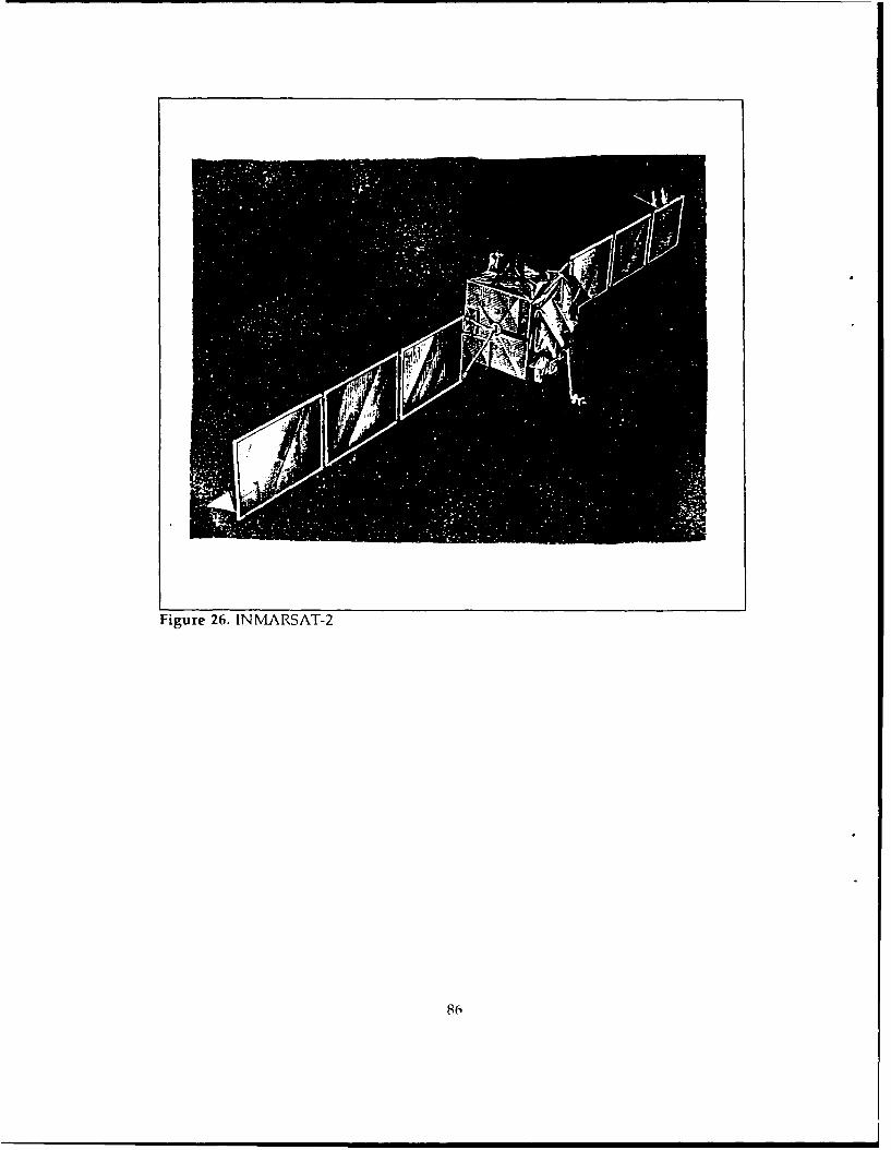
Figure 26. INMIARSAT-2
86

V. SATELLITE COMMUNICATIONS VULNERABILITY
A. INTRODUCTION
Although the frontier of space offers many unique and attractive advantages, it is not
without some countervailing disadvantages and limitations.
A given satellite is but one part of a complex space system whose proper functioning
requires a launch system, command and control network, and communication links to
connect the system's user, usually on the ground, with the orbiting satellite. To disturb the
proper functioning of a typical space system, it is necessary only that anyone of these four
subsystems fail or be made to be fail. [Ref. 24:p. 891
Secondly, many of the space systems depend upon more than one satellite in order
to function. As increasing numbers of the system's satellites fail, the system is successively
degraded.
Another important point to keep in mind is that space systems tend to be inherently
fragile. Because they are very expensive to build and to launch, space systems are usually
designed to the limit and possess little in the way of performance margin. This makes them
inherently vulnerable either to unintentional accident such as an occasionally uncooperative
environment, internal failure, or human neglect, or to the direct malevolent action of an
opponent. [Ref. 24:p. 891
Space is not a completely benign environment. Satellites must withstand extreme
temperature changes, and the near-vacuum of space offers little protection from external
sources of radiation, particularly the sun. And even if the environment of space is less
hostile than that of earth, the satellite still has to get there. The shock and vibration stresses
87

encountered during launch are severe, and special care must be given to a satellite's
mechanical engineering to enable it to survive these conditions. Also, satellites have to be
able to endure generally without maintenance. Subsystem redundancy in which virtually
all black boxes are duplicated and cross-connected, is standard practice throughout the
space industry. [Ref. 24:p. 901
B. THREATS TO COMMUNICATION LINKS
There are several things that can disrupt communications without any help from an
opponent, such as interference, atmospheric fades, and, of course, failures of
communications equipment.
In a general sense, there are three basic strategies that an enemy might seek against
each of the four communications links:6 [Ref. 24:p. 1001
" Attempt to make use of the link himself to his own advantage.
" Attempt to deny the use of the link to the legal user.
" Attempt to inject his own signal into the link with the intention of deceiving eitherthe system itself or a user of the system.
The means by which an opponent might attempt to carry out the above strategies
include: [Ref. 24:p. 1011
" Collection, which consists of passive interception and perhaps recording of the targetsignal.
" Jamming, which involves the deliberate transmission of a competing signal at thesame frequency as the target signal with the intent of interfering with its reception.
• Spoofing, which consists of the deliberate transmission of a signal that looks verymuch like the true target signal with the intent, not of interfering, but deceiving thelegitimate user.
6Ground to satellite (uplink), satellite to ground (downlink), ground to ground througha satellite (throughlink), and satellite to satellite (crosslink).
88
1. Uplink
Command links or uplinks probably present the widest range of choices for the
opponent. He could temporarily deny or limit the use of the satellite by jamming the link.
If this happens at a critical time, such as during the launch phase, the effect may even be
catastrophic and permanent. Also, he could intercept the signal in order to gain important
information about the satellite's purpose and the way it is controlled. But the greatest
threat to an uplink, in terms of potential mischief, is spoofing. If an opponent is able to
generate his own set of commands and make the satellite act on them, there is no limit,
within the bounds of satellite's capability, to what he .an do. Also, if done carefully,
spoofing is virtually undetectable and almost impossible to prove. [Ref. 24:p. 101]
Fortunately, for each of the above actions, there are countermeasures, such as
employment of frequency agility or band spreading against the threat of jamming,
encryption against the threat of interception, and some means of validating the authenticity
of a transmission against the threat of spoofing. [Ref. 24:p. 1011
2. Downlink
Geometry makes downlinks much harder to attack than uplinks, this is in spite
of the fact that the size of the downlink transmitting antenna as well as output power have
to be limited. More than compensating for the latter limitation is the fact that the receiing
antenna on the ground can be quite large and, as a result, can be highly directional,
focused at the satellite itself.
Collection of the downlink signal is a relatively easy matter, but to spoof it or
to actively jam it almost requires that the opponent situate himself within the beam of the
receiving antenna, that is, between the antenna and the satellite, which is very difficult to
accomplish without detection. [Ref. 14:pp. 93-1021
89

3. Throughlink
Throughlinks can be targeted either on the way up or on the way down. To an
opponent, the upward path of a throughlink is very much like an uplink and the
downward path much like a downlink. The earth to satellite path is easier to jam or spoof
and can be collected by a receiving station very close to the transmitter or from a mobile
receiving station such as an airplane or satellite that is within the beam of the upward
path. The satellite to earth path is easier to collect but harder to jam or spoof. However,
since on a throughlink the information on the upward and downward path is the same,
if the opponent has decided to collect he will target the downward path, and if his choice
is to jam or spoof he will concentrate on the upward path. [Ref. 24:p. 102]
4. Crosslink
Crosslinks present the most formidable task to the opponent, and therein lies
much of their value. A successful attack against a crosslink would almost have conducted
from an orbiting position somewhere between the two communicating satellites. In order
to accomplish all three hostile actions of collection, jamming, and spoofing would require
a position between the two satellites. Collection could also be carried out from behind the
receiving satellite but not from behind the transmitting satellite. Jamming or spoofing could
be accomplished only from behind the transmitting satellite. [Ref. 24 :p. 102]
C. JAMMING SIGNALS
In the previous decade most electronic warfare efforts concentrated in the area of
radar systems. Communication EW played a secondary role. In this decade, the importance
of communication countermeasures and countercountermeasures has gained ever
increasing recognition and implementation.
90

Communication jamming is more difficult than radar jamming since communication
involves a one-way-path signal attenuation, rather than a two-way-path attenuation as
radar; also encryptiun is used in communication to generate message security.
In applying jamming to a communication link it would be desirable to know the
answers of two fundamental questions. [Ref. 23:p. 181
* What is the best jamming waveform and strategy?
* How effective will jamming be against the system?
1. Interception and Jamming
The possibility of jamming is not taken into account in the design of commercial
satellite systems. The very successes of UHF satellite communications systems in
minimizing detection due to emitter interception has made jamming a more promising
alternative to a possible enemy.
2. Jammer Description
Communications links can be jammed by the following two types of jammers:
(Ref. 1 4 :p. 931
* Noise jammers
" Repeaters
Noise jammers include all systems that generate and transmit their own signal for
the purpose of degrading the effectiveness of the victim electronic system such as:
[Ref. 22:p. 1171
e Spot- Noise Jamming
& Barrage Noise
* Multiple Swept Jammers
91
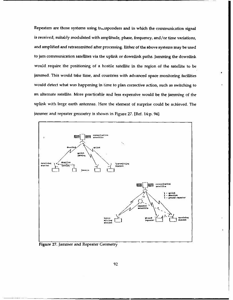
Repeaters are those systems using traasponders and in which the communication signal
is received, suitably modulated with amplitude, phase, frequency, and/or time variations,
and amplified and retransmitted after processing. Either of the above systems may be used
to jam communication satellites via the uplink or downlink paths. Jamming the downlink
would require the positioning of a hostile satellite in the region of the satellite to be
jammed. This would take time, and countries with advanced space monitoring facilities
would detect what was happening in time to plan corrective action, such as switching to
an alternate satellite. More practicable and less expensive would be the jamming of the
uplink with large earth antennas. Here the element of surprise could be achieved. The
jammer and repeater geometry is shown in Figure 27. [Ref. 14:p. 94]
/d, I in
B~tell t:±1 up1iitii
@ter - .r~.d reIeate~r
Figure 27. Jammer and Repeater Geometry
92

The objective of a jammer is to obscure or deny information by masking or increasing
the error probability of the detected data. Jammers can be evaluated by the ratio of the
jamming signal bandwidth to the communication receiver bandwidth. This ratio is very
small for the CW jammer. This appears effective since all jam power will be focused in the
receiver bandwidth but notch filters may easily overcome CW jammers.
[Ref. 23:p. 18]
With repeaters, the idea is to receive the signals, process them and retransmit. This
is difficult because it is hard to obtain the geometry which is required to effectively use of
repeaters. In cases where we manage to achieve the geometry we must carefully use the
modulation or delay techniques because a straight repeater is worse than no jamming at
all if there is no modulation since it increases the signal power. One advantage of repeaters
is that with this technique we are able to operate at the same time against many links.
[Ref. 23 p. 211
3. Jamming of links using FDMA/PSK
The basic characteristics of jamming with FDMA/PSK are: [Ref. 18:p. 24]
- Since there is no spreading there is no processing gain and the jammer requires nomore Effective Isotropic Radiated Power (EIRP) than the signal. This results in lesspower than in the spread spectrum case.
* The psychological effect which sometimes appears on the jammed channels becauseof the use of narrowband jammers against some of the users without interfering withthe others.
9 The carrier local oscillator of PSK receivers is generated by processing of the receivedsignal through squaring loops. In the case of FDMA/PSK since there is no spreadingprocess these circuits can be denied by breaking the loop lock.
* Pulse jamming is better than continuous jamming.
93

4. Antijamming Techniques using spread spectrum
Protection from the jamming is generally obtained by using spread spectrum
techniques, that is frequency hopping or pseudo-noise. [Ref. 14 :p. 96]
In recent years, jammers have been smarter and faster at locating, identifying,
and jamming a particular communication link. Frequency hopping offers a solution to the
problem, working by rapidly switching the transmitter carrier over many channels within
a very wide frequency band. Typically, more than 1000 channels may be used and the
switching rate may exceed 100 hops per second. Because an enemy cannot be certain when
or where transmissions will take place, his jammers must constantly search the spectrum
for the signal he expects to jam; thus frequency hopping, which results in short duration
transmissions would be effective.
Jamming effectiveness depends upon relative signal strength, dwell time (DT),
and the jammer's processing time (PT). If we suppose that we have the maximum signal
strength and PT is defined as the time from the target signal's first appearance to the time
a jammer can direct energy against a target receiver operating in that net, then the formula
for jammer effectiveness as a function of PT, DT, and range is: [Ref. 14:p. 991
%jammed= 100* [DT-2 *(6.18 *range) -PT)DT
Shortening the DT is a good method for overcoming a jammer, because a shorter DT makes
propagation delay significant and jammer-target ranges more critical. Even with an
instantaneous PT, a jammer must be within 61 nautical miles to be 25% effective against
systems with one millisecond DT. A more realistic 400 microsecond PT requires the jammer
94
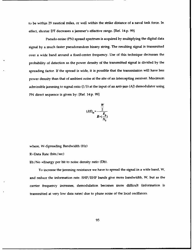
to be within 29 nautical miles, or well within the strike distance of a naval task force. In
effect, shorter DT decreases a jammer's effective range. [Ref. 14:p. 991
Pseudo-noise (PN) spread spectrum is acquired by multiplying the digital data
signal by a much faster pseudorandom binary string. The resulting signal is transmitted
over a wide band around a fixed-center frequency. Use of this technique decreases the
probability of detection as the power density of the transmitted signal is divided by the
spreading factor. If the spread is wide, it is possible that the transmission will have less
power density than that of ambient noise at the site of an intercepting receiver. Maximum
admissible jamming to signal ratio (J/S) at the input of an anti-jam (AJ) demodulator using
PN direct sequence is given by: [Ref. 14:p. 991
W
(IS), 2R *( -o)No
where, W=Spreading Bandwidth (Hz)
R=Data Rate (bits/sec)
Eb/No =Energy per bit to noise density ratio (Db).
To increase the jamming resistance we have to spread the signal in a wide band, W,
and reduce the information rate. SHF/EHF bands give more bandwidth, W, but as the
carrier frequency increases, demodulation becomes more difficult (information is
transmitted at very low data rates) due to phase noise of the local oscillators.
95

5. Uplink-Downlink Jammer
a. Uplink Jammer
For a transparent repeater the protection ratio can be expressed by:
[Ref. 14:p. 1011
~ JL, *k*(.w[)
S iS" L EIRPs*(G)RT
where (J/S)u = Jamming to signal ratio.
Gs =Satellite antenna gain in the signal direction
Gj =Satellite antenna gain in the jammer direction.
Lp =Down link free space propagation losses.
EIRPs =Saturated satellite EIRP at beam edge.
(G/T)R =Receiving terminal G/T.
L =Limiter suppression factor.
k =Boltzmann's constant.
To improve the uplink (J/S)u, it is necessary: [Ref. 14:p. 101]
* To use a satellite reception antenna with very high directivity.
* To concentrate the power radiated by the satellite in the direction of the smallterminals to have EIRPs (G/T)R >> Lp k w/2.
For on-board AJ processing the protection ratio is only defined by:
(Ref. 14 :p. 1021
96

Wj G5 2
No
b. Downlink Jammer
The acceptable jammer EIRP on the downlink is given by: [Ref. 14 :p. 102]
G*djJ=EIRP,* G* d3 S
where, Gs =Antenna gain of the terminal user in the satellite direction.
Gj =Antenna gain of the terminal user in the jammer direction.
ds =Distance to satellite.
dj =Distance to jammer.
Generally, a jammer has an important distance advantage compared with
a geostationary satellite, but it can see only a very limited area. To protect the downlink
under high RF satellite power, it is required to reduce the coverage area and use a terminal
with high directivity antenna.
D. SUMMARY AND CONCLUSIONS
Satellite communication links using digital PN spread spectrum and FDMAtechniques are vulnerable to jamming and denying signals. Two types of interferingsignals were discussed, noise jammers and repeaters; each requires a specificgeometry to be used effectively. In the jamming of FDMA by noise jammers it isnecessary to overcome the signal power to increase the Bit Error Rate (BER). In thiscase there is a potential advantage of a selective jamming, as the jammed user mayfeel he is having system problems.
97
* For spread spectrum jamming the disadvantage in overcoming the processing gainby brute force techniques is apparent. CW jamming is an efficient utilization ofpower but can be easily filtered.
" A repeater technique can be used to break the delay lock loop if the repeated signalis within one chip; however, this may be difficult to achieve in practice as a resultof propagation delay.
" The various jamming techniques against satellite communications are shown in Table12 [Ref. 18:p. 231.
" Jammers can be located on ground or sea platforms and on satellite or airborneinstallations, while the jamming can be done through the uplink or downlink paths.The uplink has the advantage of potentially stealing the satellite transponder powerand generating intermodulation products. In downlink jamming the jammer'sdistance from the receiving station is usually shorter than the communication pathlength, allowing a power advantage over uplink jamming. In contrast to the uplinkcase the downlink jammer has limited access to users.
a. Frequency hopping vs Jammers
Frequency hopping signals are of the LPI type, thus providing increased
capability for covert communication and strong resistance to interference and jamming.
Frequency hopping offers an antidote to smart jammers. Because an enemy
never is certain when or where transmissions will take place, his jammers must search the
spectrum for the signal he hopes to jam.
The effectiveness of the jammer depends upon the friendly on the air dwell
time (DT), the jammer's processing time (PT), and relative signal strength.
Concluding, we can say that:
The higher the hoping rate, the less time a jammer has to disrupt
communication.
98

Table 12. JAMMING TECHNIQUES
D CA .I Sligoc-JAMERt TYPE I's ,1m 13KAA.a 11 MZARKS
1. Clo of very Tnerov tf111111. -Iltnoot Rinh efficiency Etfetiwe with "my be flteredbond signal ilni .1" Jf eto mitu. nor JSP 'I ceiseini eot by match
derend, on th show ,$It4 t pred.. the *epue filter If theable SIr. tath filter may offet* signal SWv It
be susedi without narrow, ihu,,shde31,11 the causes loss ofca-mU,,ication 1none informationor'.ctrum. in f14.
2. 1"ot tool9e 9..e ae klin. Be' ins. rower then r.ff-ett.0 vith The ipot I&.'etInorro-bend..oattel cw in the post d";- jSpt I If InOite war he mophist-
s PTO@ Iny heI. . dig bi ices.1 then itented. j.t 1 'ieijroradlio. the rN SW. power yoeneqewmnt.1rd to (Liter out. eon be weed to
get the jswperfrequency at the
approprilateftequency.
1. .-pt spot Can he useA eq~iinlt Cn hop ustA eailnst Due to recoverinj g.tepinq if,
at 51W 1Oy7fl an link.. Ii.,s the~ -11y links. if tine oc the PCVll. patterne whichbl 111ho L ' edantaiqe of Putting. over~t over mote then jereaing at the ate not tindom,C) SI'IUS011DAL If sone jsoennr at, the transponder epoprpts rate maey be filtered61 ItAtIfO" lynehr')oite.1. this fanodfwdtft. thus 1" "o e fficient au Ila*o
.113~pi mode causes higher hivlnq on off than continuous fiter.Avereq" OCR. effect ageinst each joameinsq.
of them. Sweepin,aods and pecrmterceo determined foretch target.
4. Vit shit"~ APPACE Can he "sod ealost jao~wtnq PC-Ier must !nexteees the noiseWntfnrte .iitri- many links. jtl' b- greater the.n level. JSR vnpot bebut-d 110111 owor dep-ndi -n the signal by the greater then thethe bend-idth). required Sent. pmocessin7 gain due threehold.
to ospreading offsect.
S. PIJIAID SAPSACE With thn sam A~fter ochiewin,; the 2eee of SWEPT SPOT.average power, 355 to ovecmes thehigher peeok pawor sreading. tau-e$can be ,s-pd thi,v hilh-r eVICrny egceullin higher than continuousaverage erm. esiq
6. Putito SPOT Can be usedi It 3311 to overome seome I MIqTunIleoltentlusIy h peaiih SPOT but canagainst vinqI9 or aev~sed hee Bowie' be ;,red again-itfev itk, nigh effect ae in MwIA. fin Is link.Peeks9 cause high
1. pfCATIO Sleciel Tachniluec In q peelat eonmotry Adding wodule-of SYPIptClT I of frequency -sy break t:1e tic" and/orbi DELATto shifting nOy cause sequince sync freuinyCI pobuIJfl'%I oterrr to the Costs$ 0sin. a de tape~d .hiltinq within
5070loop. very Ie of the the eon-Iutdth my901"al.be eyed.
a. POUlD cla Same et 7Pilitr" In deqrteeding game as SWEPT The pulseJ widthfret. Pulsed Cos has troy. he be w ide
highest pof in ini order not toeqrvelet-jr Pvt. spread theDue to high peakPo,,er. c uae Ihigaverage SEN.
9. IWTF? CW Very mff-ctive ISae effect as lan so e as Special tech"IlueSince It ren steel OAHRMsC. against .L.L.the lomelt clri~If the s9ePr 1ealow enoumgh.
DET1i4muo0eS. 43 - om.r-to-1sIqns Crlo
IR-it err rae
99
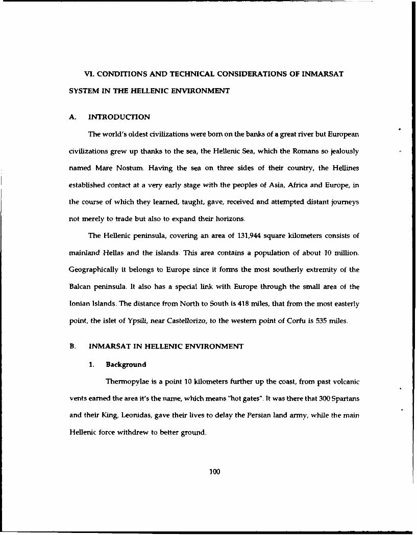
VI. CONDITIONS AND TECHNICAL CONSIDERATIONS OF INMARSAT
SYSTEM IN THE HELLENIC ENVIRONMENT
A. INTRODUCTION
The world's oldest civilizations were born on the banks of a great river but European
civilizations grew up thanks to the sea, the Hellenic Sea, which the Romans so jealously
named Mare Nostum. Having the sea on three sides of their country, the Hellines
established contact at a very early stage with the peoples of Asia, Africa and Europe, in
the course of which they learned, taught, gave, received and attempted distant journeys
not merely to trade but also to expand their horizons.
The Hellenic peninsula, covering an area of 131,944 square kilometers consists of
mainland Hellas and the islands. This area contains a population of about 10 million.
Geographically it belongs to Europe since it forms the most southerly extremity of the
Balcan peninsula. It also has a special link with Europe through the small area of the
Ionian Islands. The distance from North to South is 418 miles, that from the most easterly
point, the islet of Ypsili, near Castellorizo, to the western point of Corfu is 535 miles.
B. INMARSAT IN HELLENIC ENVIRONMENT
1. Background
Thermopylae is a point 10 kilometers further up the coast, from past volcanic
vents earned the area it's the name, which means "hot gates". It was there that 300 Spartans
and their King, Leonidas, gave their lives to delay the Persian land army, while the main
Hellenic force withdrew to better ground.
100

The heroic battle brought the name into history and adds a special significance to the
unique coast earth station located there.
2. Thermopylae's Coast Earth Station
Thermopylae's coast earth station which covers the Indian Ocean region
operates in cooperation with the new Italian CES at Fucino, which covers the Atlantic. This
arrangement enables the two stations to operate as though they were a single, two ocean
station, with economic benefits to the users in both countries.
At present, Thermopylae has three telephone and four telex lines to Italian
exchanges, although there is one less of each in the opposite direction on the premise that
ship-to-shore traffic is greater than shore-to-ship. The same reasoning explains the choice
of six telephone and seven telex lines from the station to Athens, compared with four
telephone and five telex lines back from the Hellenic exchange. There are also dedicated
lines to the Athenian maritime rescue coordination center. Apart from telephone and telex,
a number of services attainable by a two digit dialing codes are being provided, notably
medical service, technical assistance, general information, operator assistance and ship-
earth station commissioning. [Ref. 25:p. 2]
The Thermopylae station is the first outside of Norway to be supplied by the
Norwegian firm, Elektrisk Bureau (EB). The EB content is 60% of total cost. The antenna
and C-band RF equipment were bought from United Antennas Inc. of the USA.
Technically, the CES demonstrates an innovative philosophy. The aim, according
to the manufacturers, was to keep costs down on the standard equipment, the antenna and
RF equipment, and to concentrate on the complicated part, which is the access control and
switching equipment. The antenna itself is a minimum structure carrying no equipment
on it other than the low-noise receiving amplifiers. It is also designed for only limited
101

motion, capable of a maximum azimuthal range of 180 degrees. Even that is constrained
to two segments of 90 degrees, selected by manually reattaching the drive screw to one end
or the other of a cross beam behind the dish. However, this is sufficient to provide
coverage of either the Indian or Atlantic Oceans.
3. Services provided and Dialing procedures
a. Services
The two-digit service codes and the corresponding services provided by
Thermopylae CES are:
* Automatic telephony and telex ..................... 00
" Operator assisted calls (Intern. /National) ....... 11/13
" International/National Inquiries ........................ 12/24
* Radiotelegrams (telex) ..................... 15
" Technical assistance ...................................... 33
" Person to Person calls (telephone) ................ 34
" Medical advice (telephone) .............................. 32
" Automatic call duration advice (telephone) ........ 37
* Automatic telex test messages .................. 91
" SES commissioning test ............................... 92
" Collect calls (National telephone calls) ........ 35
" Credit Card calls ...................................... 36
102

b. Dialing procedures
(1) Sending a telex to a ship fronm Greece
Key international access code (00) followed by the ocean region, ship
ID and "end of selection" sign. Figure 28 shows how to send a telex to a ship (ID 1130501)
in the Indian Ocean Region.
00 583 1130501 +Oc..n OI..g(Ioa c~l go" nu't.'r E8 6 .ICIi
Figure 28. Sending a telex to a ship from Greece
(2) Making automatic calls front a ship
After selecting the identification code for Thermopylae (05 in octal
and decimal notation), priority, and channel type (voice channel), you receive a short dial
tone (about 1.5 sec). At the tone dial the automatic service code (00) followed by the
country code, the subscriber's number and the "end of selection" sign.
103
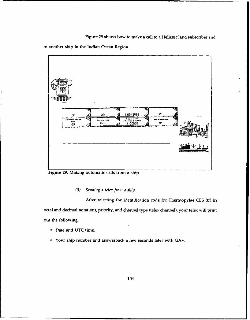
Figure 29 shows how to make a call to a Hellenic land subscriber and
to another ship in the Indian Ocean Region.
Figure 29. Making automatic calls from a ship
(3) Sending a telex froiii a ship
After selecting the identification code for Thermopylae CES (05 in
octal and decimal notation), priority, and channel type (telex channel), your telex will print
out the following:
* Date and UTC time.
* Your ship number and answerback a few seconds later with GA+.
104

When you receive GA+, you are free to start keying code: automatic
service code (00), telex country code, subscriber number and "end of selection" sign.
Message duration is provided at the end o the message by keying five dots << ..... >>.
Figure 30 illustrates calls, to a land subscriber, and to another ship
in the Indian Ocean Region.
00j 583 1130501
Figure 30. Sending a telex from a ship
(4) Making a call to a ship from Greece
The call is operator assisted. In Athens, Piraeus and their suburbs dial
158. All other regions dial 161. Ask the operator for INMARSAT service and give the ship
ID and details for the ship's area.
105

C. ECONOMICS OF SATELLITE BUSINESS SERVICES
1. Background
The economics of satellite communications have many unusual aspects. It costs
no more to transmit a television signal via satellite to one, one hundred, one thousand or
even one million receivers. Satellites are also able to interconnect locations thousands of
kilometers apart on a distance-insensitive basis. In other words, satellite
telecommunications links, in general, cost the same over short and very long-range
distances. As a result, they are better suited for certain applications than terrestrial
telecommunications, like microwave relay, coaxial and optical fiber cable. [Ref. 3:p. 49]
2. Economically Relevant Technical Propertiep of Satellites
The most important difference between space-based and terrestrial
communication systems concerns the relationship between cost and transmission distance.
For all terrestrial systems, total cost varies directh, - -h distance although various fixed
costs make this relationship propoti,,ai. For example an important cost component of
cable technologies is the expensive hierarchical switching required to achieve
interconnectivity. Besides distance, the cost of terrestrial modes of communication also
increases with difficulties imposed by terrain and climate between the sending and
receiving points. [Ref. 3:p. 491
Satellite technology, by contrast, is inherently insensitive to the distance of
transmission, at least within the satellite's coverage zone.
These cost properties imply that the economic advantage of satellites over
terrestrial transmission modes is most pronounced when long distances, difficult terrain,
severe climate and sparse population are involved.
106

3. Charges for INMARSAT services in Greece
The charges for the various services provided by the INMARSAT system
through Thermopylae CES are shown in the following tables: [Ref. 26:pp. 1-331
Table 13. SHORE-TO-SHIP END USER CHARGES
1 1l Q h o n t
Atlantic IninPaii
minimum time 3 mins 3 mine ',insUnit charge 60 G.F. 00 G.F. 84 G.F.Overtime I min 1 min i minUnit charge 20 G.F. 20 G.F. 28 G.F.
Telex
Atlantic Indian EAI1"Minimum time and 10 secs 10 secs 10 secsovertimeCharge per minute 10 G.F. 10 G.F. 15 G.F.
Minimum length 7 wordsCharge per word 1.50 G.F.Minimum charge 10.50 G.F.
H 9lE
Telephone and telex calls from foreign countries to ships in the IORvia Thermopylae CES are charged with the CES charge of 18 G.F. per min.for telephone and 9 G.F. per min for telex, plus the existing land linecharge between Greece and the country of origin.
7
7G.F stands for Golden Franc which as of January 1991 equals to 0.65 of the dollar.
107
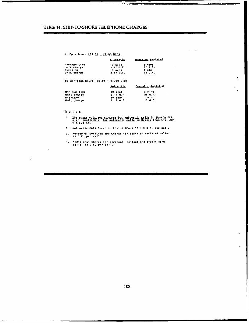
Table 14. SHIP-TO-SHORE TELEPHONE CHARGES
a) Dwii- howlr £91-Q-1 =. 22-QQ ULTS
&LtLQMAkiz QD1,LAI2 Asishted
Minimum time 10 scq 3 mineUnit charge 3.17 G.F. 57 a.F.Overtime 0 aeca I mnUnit, charge 3.17 G. F. 1 G,F.
4
b) WLokqs hours L22-.L 0_-4.00 I.I,.
Minimum time 10 sacs 3 min$Unit charge 2.11 G.F. 39 G.F.Overtime IO secs I mnUnit charge 2.17 0.F. 13 G.F.
I. lIDl DbQY l end-:vilejx v rl.q l '[ b mtiS rj.1 g GrIzs1 Ar[t*110 fliC b" LOL Au ibc calls t2 Grece fLm .bl A0Y-Ln USw.09
2. Automatic Call Duration Advice (Code 37): 3 G.F. per call.
3. Advice of Duration and Charge for operator easeted cells:14 G.F. per call.
4. Additional charge for Dersonel, collect and credit cardcalla: 14 0.F. per call.
108

Table 15. SHIP-TO-SHORE TELEX CHARGES
END-USE CHARGES FOR MSAGES TO GREECE
Automatic Operator Assisted
Minimum time 10 secs 3 minsUnit charge 1.50 G.F. 27 G.F.Overtime 10 secs 1 minUnit charge 1.50 G.F. 9 G.F.
1. The Abov end-user harqees for automatic telex calls J oGreeceare also Aol icable for automatic telex calls to Greece from theAOR via Fucino.
2. In automatic telex mode, if Call Duration Advice is required,- key 5 dots at the end of the message.
109
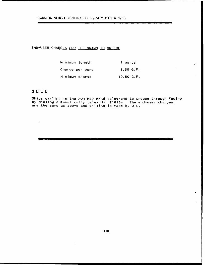
Table 16. SHIP-TO-SHORE TELEGRAPHY CHARGES
END-USER CHARGES FOR TELEGRAMS TO GREECE
Minimum length 7 words
Charge per word 1.50 G.F.
Minimum charge 10.50 G.F.
Ships sailing in the AOR may send telegrams to Greece through Fucinoby dialing automatically telex No. 210184. The end-user chargesare the same as above and billing is made by OTE.
110
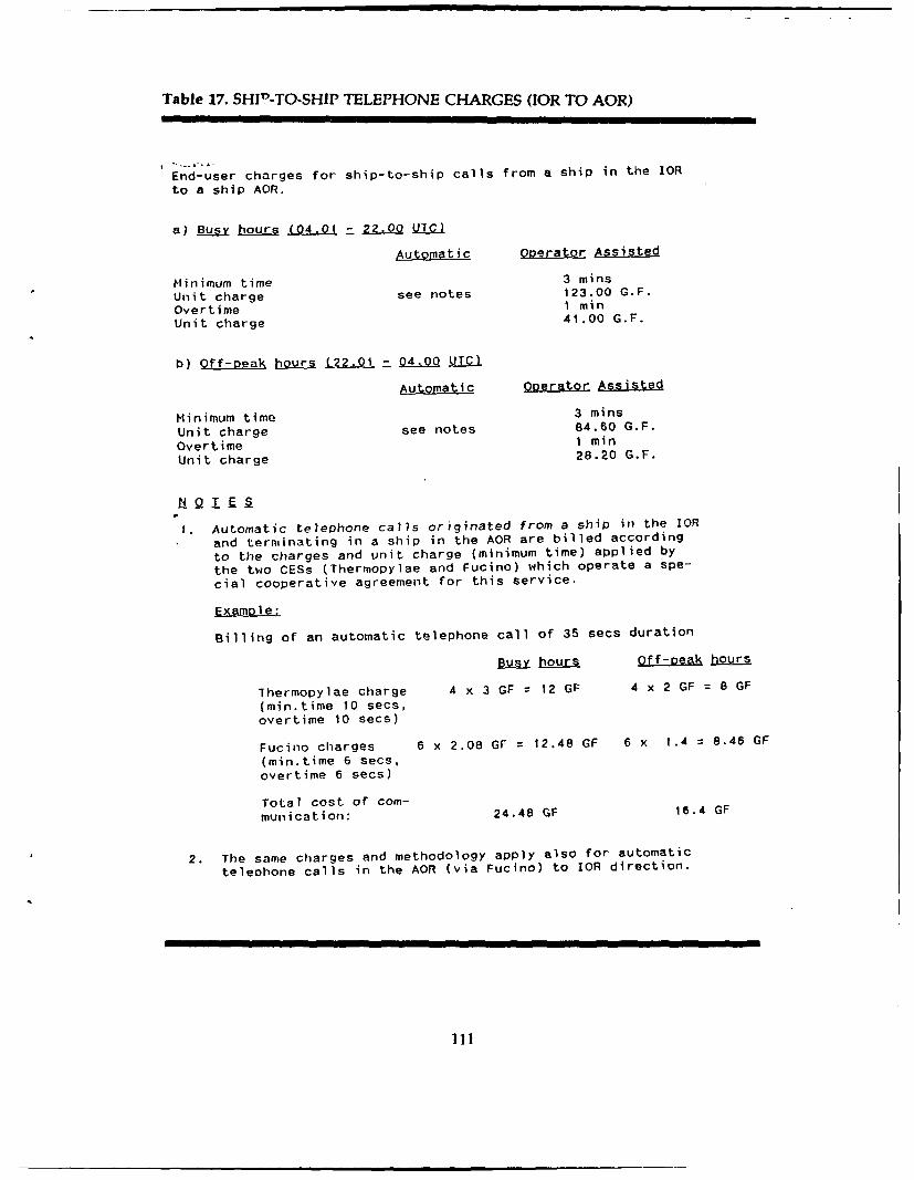
Table 17. SHIP-TO-SHIP TELEPHONE CHARGES (JOR TO AOR)
End- user charges for ship-to-ship calls from a ship in the IOR
to a ship AOR,
a) y hours (04.01 = 22.0 ULIS
Automatic Operatop Aisted
Minimum time 3 mins
Unit charge see notes 123.00 G.F.
Overtime I minUnit charge 41.00 G.F.
b) Off-peak hours L222,=9_Z.& Q UTC)
Automatic QPI_ site
Minimum time 3 mins
Unit charge see notes 84.60 G.F.
Overtime 1 min
Unit charge 28.20 G.F.
1. Automatic telephone calls originated from a ship in the IOR
and terminating in a ship in the AOR are billed according
to the charges and unit charge (minimum time) applied by
the two CESs (Thermopylae and Fucino) which operate a spe-
cial cooperative agreement for this service.
Example:
Billing of an automatic telephone call of 35 secs duration
Bs hours 0ff-peak hours
Thermopylae charge 4 x 3 GF 12 GF 4 x 2 GF 8 GF
(min.time 10 secs,overtime 10 secs)
Fucino charges 6 x 2.08 GF 12.48 GF 6 x 1.4 = 8.46 GF
(min.time 6 secs,overtime 6 secs)
Total cost of com-munication: 24.48 GF 16.4 GF
2. The same charges and methodology apply also for automatic
telephone calls in the AOR (via Fucino) to IOR direction.
ill
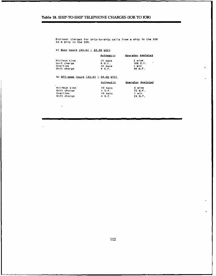
Table 18. SHIP-TO-SHIP TELEPHONE CHARGES (IOR TO IOR)
End-user charges for ship-to-ship calls from a ship in the IORto a ship in the IOn.
a) Dw hours (04.01 -_ 22.0 jQLj
Automatic Qoerator Assisted
Minimum time 10 secs 3 mins
Unit charge 6 G.F. 108 G.F.Overtime 10 secs I minUnit charge 6 G.F. 36 G.F.
) Off-peak hours (2.01 04-00 U]
Automatic Operator Assisted
Minimum time 10 secs 3 mlnsUnit charge 4 G.F. 72 G.F.Overtime 10 Secs I minUtit charge 4 G.F. 24 G.F.
112

Table 19. SHIP-TO-SHIP TELEPHONE CHARGES (IOR TO POR)
End-user charges for ship-to-ship calls from a ship in the IORto a ship in the POR.
a) Busy hours f04.01 7- 220Q !_I
Automatic Operator Assisted
Minimum time 10 secs 3 minsUnit charge 7.17 G.F. 129.00 G.F.
Overtime 10 secs I min
Unit charge 7.17 G.F. 43.00 G.F.
b) Off-peak hours (22.02 - 04Q UTrS
Automatic Operator Assisted
Minimum time 10 secs 3 minsUnit charge 6.17 G.F. 111.00 G.F.
Overtime 10 secs I minUnit charge 6.17 G.F. 37.00 G.F.
113

Table 20. SHIP-TO-SHIP TELEX CHARGES (IOR TO AOR)
From I p to A 2
End-user charges for ship-to-ship messages from a ship in theIOR to a ship in the AOR.
Automatic Operator Assisted
Minimum time 3 minsUnit charge see notes 60 G.F.Overtime 1 minUnit charge 20 G.F.
1. Automatic telex calls originated from a ship in theR ndterminating in a ship in the AOR are billed according to thecharges and unit charges (minimum time) applied by the twoCESs (Thermopylae and Fucino) which operate a special coope-rative agreement for this service.
Example:
Billing of an automatic telex call of 35 secs duration
Thermopylae charges 4 x 1.5 GF = 6 GF(min.time 10 secs, overtime 10 secs)
Fucino charges 6 x 1GF = 6 GF(min.time 6 secs, overtime 6 secs)
Total cost of communication: 12 GF
2. The same charges and methodology apply also for automatic telexcalls in the AOR (via Fucino) to IOR direction.
114
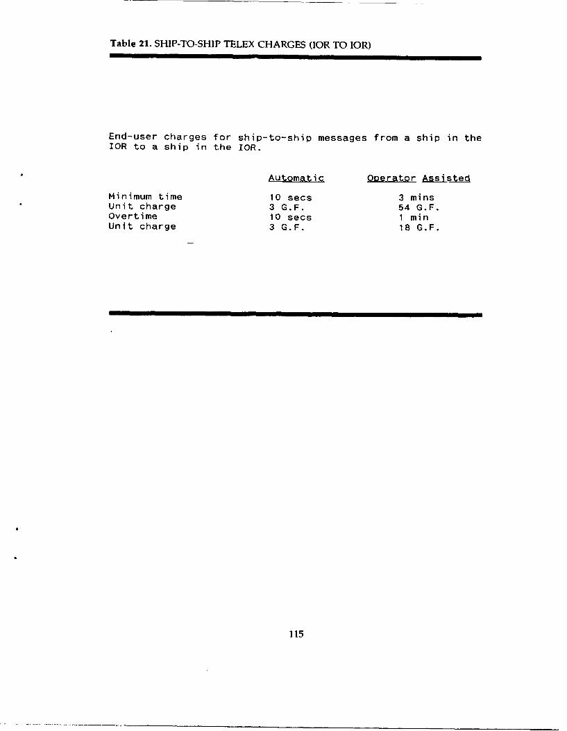
Table 21. SHIP-TO-SHIP TELEX CHARGES (IOR TO IOR)
End-user charges for ship-to-ship messages from a ship in theIOR to a ship in the IOR.
Automatic Operator Assisted
Minimum time 10 secs 3 minsUnit charge 3 G.F. 54 G.F.Overtime 10 secs 1 minUnit charge 3 G.F. 18 G.F.
115
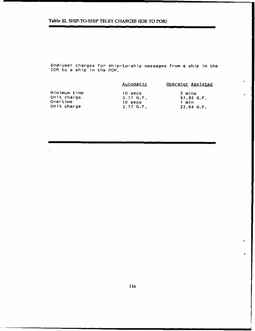
Table 22. SHIP-TO-SHIP TELEX CHARGES (IOR TO POR)
End-user charges for ship-to-ship messages from a ship in theIOR to a ship in the POR.
Automatic Operator Assisted
Minimum time i0 secs 3 minsUnit charge 3.77 G.F. 67.92 G.F.Overtime 10 secs 1 minUnit charge 3.77 G.F. 22.64 G.F.
116
D. TECHNICAL CONSIDERATIONS FOR INMARSAT IN THE HELLENIC
ENVIRONMENT
As in any other communications system, the ultimate goal of a satellite system is to
provide a satisfactory transmission quality for signals relayed between earth stations. We
know from previous chapters, that a satellite link consists basically of an uplink and a
downlink. Signal quality over the uplink depends on how strong te signal is when it
leaves the originating earth station and how the satellite receives it. On the downlink, the
signal quality depends on how strongly the satellite can retransmit the signal and how the
destination earth station receives it. Because of the great distances between a geostationary
satellite and the earth stations and because the power , he radiated signal diminishes as
the square of the distance it travels, the uplink signal received by the satellite and the
downlink signal received by the earth station are very weak and can be easily disturbed.
In addition, the uplink signal may be contaminated by signals transmitted by other earth
stations to adjacent satellites, and the downlink signal may be contaminated by signals
coming from adjacent satellites. Furthermore, rain can severely attenuate satellite signals
above 10 GHz. All these factors must be taken into consideration in link budget
calculations. [Ref. 4:p. 130]
1. Uplink and Downlink calculations
The area of the earth seen by a satellite at any moment is bounded by a circle
whose radius depends on satellite altitude H and earth antenna elevation angle E.
Although a geostationary satellite is visible from about the 42% of the earth's surface,
whether or not a station is in line-of-sight depends upon its angle of elevation relative to
117

the fixed satellite position. The geometry of coverage angle and slant range is shown in
Figure 15 (page 31). For the Hellas case we have: [Ref. 4:p. 45]
sin(a)=[Re*cos(E)]/(Re+H) (1)
Re= 535/2=495 Km (2)
Re+H = 36279 Km (3)
where a=coverage angle.
H=Altitude of satellite's orbit (geostationary satellite).
Re=Hellas area radius.
Equations (1),(2),and (3) imply
sin(a)=495/36279--0.01368 and a--0.78 degrees
The slant range d, which is the distance between satellite and Hellas, is:
d= sqrt [(Re+H)A2 +(ReA2) -(2*Re*(Re+H)*cos(w))] (4).
w= 90 - E - a = 90 - 23 - 0.78 = 66.22 degrees (5).
H = 35784 Km (6).
where w =angular radius of the satellite footprint,
E= elevation angle which is 23 degrees for CES Thermopylae.
Equations (4),(5),and (6) imply d = 36082 Km.
In a digital satellite system the performance of the satellite signal received at an
earth station is measured in terms of the average probability of bit error, which is a
function of the link carrier-to-noise ratio (C/N). In order to calculate the the carrier-to-noise
ratio of the overall satellite link (uplink and downlink) we have to calculate first the
carrier-to-noise ratio of the uplink and downlink. The following is an example of the
Uplink and Downlink calculations for a CES-Satellite-Ship communication link from the
118

Thermopylae CES. For the downlink calculations the same elements are used as in the
Uplink. [Ref. 9:p. 356]
a. Uplink calculation (Frequency 6.42 GHz)
Carrier EIRP 65 dbw
Free space loss -200 db
Antenna tracking loss -2.8 db
Satellite G/T -19.6 db/K
Boltzmann's constant 228.6 dbw/K-Hz
Noise bandwidth -46.5 db-Hz
Atmospheric attenuation -1.0 db
(C/N)u 23.3 db
b. Downlink calculation (Frequency 1.54 GHz)
Satellite EIRP 27 dbw
Free space loss -188.5 db
Antenna tracking loss - 0.9 db
Ship G/T - 4.0 db/K
Boltzmann's constant 228.6 dbw/K-Hz
Noise bandwidth -46.5 db-Hz
Atmospheric attenuation -1.0 db
(C/N)d 14.7 db8
s The above uplink and downlink calculations are in accordance with the formulasfound in References 4 and 9. The values assumed for CES Thermopylae are approximate.
119

The overall link carrier-to-noise ratio is: [Ref. 9 :p. 1341
-C =R[-C)0 1 + ---)I"
71 N N
which for our case implies (C/N) = 13.87 db
120

VII. CHOOSING A SATELLITE COMMUNICATIONS SYSTEM
A. INTRODUCTION
Previous chapters discussed satellite communication systems technologies and
provided user costs for the INMARSAT system through CES Thermopylae. This chapter
provides a brief overview of communication systems economics which would help us in
the process of evaluating and choosing a satellite communications system.
B. ECONOMICS OF A COMMUNICATION SYSTEM
Basic economics of the communication system are discussed below for background
information.
1. Economies of Scale
Figure 31 shows how system costs, communication volume, and user charges
for equipment and service are related. Because of improvements in technology, the costs
of the communication system as well as the user terminal costs (A) per unit of capacift
tend to drop over time. However, inflation influences the costs and tends to increase the
price of a product over time. The cost of equipment tends to drop as production volume
increases and time advances because cost reductions related to electronics and computer
technology are generally greater than the inflation rate. This results in a reduction of the
communication charges necessary to retrieve the costs of a system, and the price of user
terminal equipment drops (B) making the service more attractive. This increases the traffic
base (C) and the amount of price-sensitive traffic (D), creating a diversion (E) from other
alternatives. The lower prices (B) also stimulate the growth of traffic (G) and new types of
121

traffic (F). Thus, the total communications traffic carried by the systems increases (H). All
these factors above create economies of scale (I). The above process feeds back to generate
more orders for system and user equipment and further reduces communication charges
(A and B). [Ref. 9:pp 83-84
TECHNOLOGY
ECONOMIESD OF SCALE
A 0 c H
CNOSTIONR THRE IC RMOLE R V11T~JFI
COMMECUNIT OF TRAFFIC INCREASESUNIT OF CAPACITY BASE IN TRAFFIC
F CAPACITY
REDUCTIONSc
d a r
2.~ Make Dean anFupl
INFL.ATION TRAFFIC FROM OTHER GROWM "HI FC
SCOMMLKATION LINKS TTRAFFIC TYPES
SPRICE -SENSITIVE
Figure 31. Economies-of-scale diagram
2. Market Demand and Supply
A basic understanding of demand and supply helps to explain and predict the
behavior of the market in response to changing conditions. A definition of a market is a
group of firms and individuals in contact each other in order to buy or sell some good or
service [Ref.27 p:20]. The market demand for a service or good during any period of time
will usually rise as its price is dropped. Conversely, the quantity supplied to the market
during a period of time will usually rise as the price is increased. In Figure 32 we can see
the relationship between quantity and price.
122
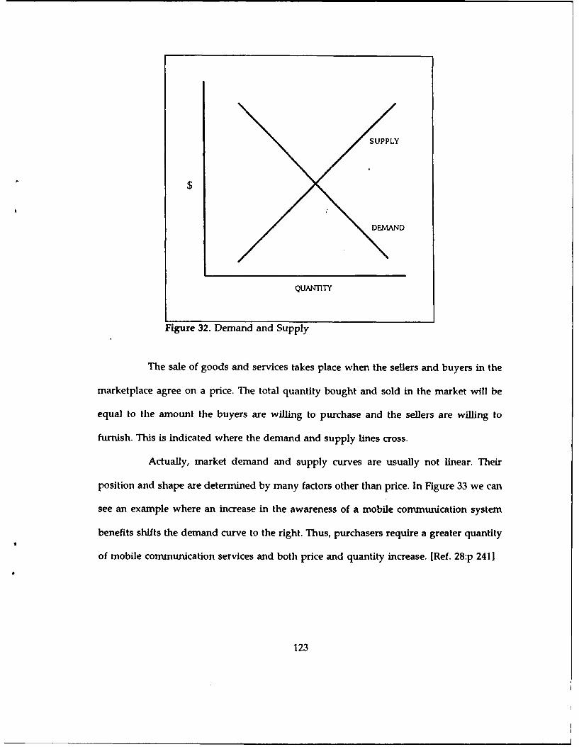
X
SUPPLY
$
DEMAND
Figure 32. Demand and Supply
The sale of goods and services takes place when the sellers and buyers in the
marketplace agree on a price. The total quantity bought and sold in the market will be
equal to the amount the buyers are willing to purchase and the sellers are willing to
furnish. This is indicated where the demand and supply lines cross.
Actually, market demand and supply curves are usually not linear. Their
position and shape are determined by many factors other than price. In Figure 33 we can
see an example where an increase in the awareness of a mobile communication system
benefits shifts the demand curve to the right. Thus, purchasers require a greater quantity
of mobile communication services and both price and quantity increase. [Ref. 2 8:p 2411
123

QUANTIlY
Figure 33. Change in the Quantity Demanded
Supply curves are affected by the level of technology, production economies of
scale and the basic costs of raw materials and components. In Figure 34 we can see the
change in quantity supplied as the result of a change in communication technology. The
supply curve has moved downward because it is now possible to provide communications
services at a lower cost and thus, the market price drops and the quantity demanded
increases.
124
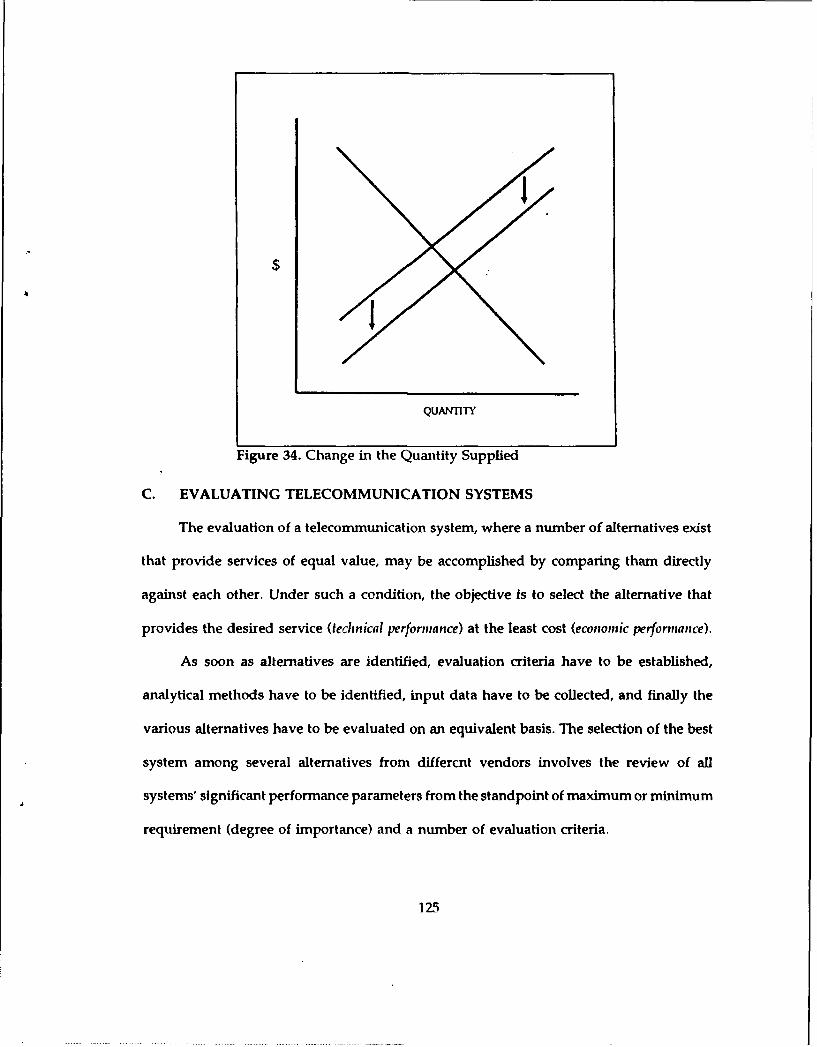
$
QUAIITTY
Figure 34. Change in the Quantity Supplied
C. EVALUATING TELECOMMUNICATION SYSTEMS
The evaluation of a telecommunication system, where a number of alternatives exist
that provide services of equal value, may be accomplished by comparing tham directly
against each other. Under such a condition, the objective is to select the alternative that
provides the desired service (technical performance) at the least cost (economic performance).
As soon as alternatives are identified, evaluation criteria have to be established,
analytical methods have to be identified, input data have to be collected, and finally the
various alternatives have to be evaluated on an equivalent basis. The selection of the best
system among several alternatives from differcnt vendors involves the review of all
systems' significant performance parameters from the standpoint of maximum or minimum
requirement (degree of importance) and a number of evaluation criteria.
125

The evaluation criteria are dependent on the stated problem and the complexity of
analysis. The most important criteria, related to the selection of a telecommunication
system among several alternatives, is cost-effectiveness, which is based on the technical
effectiveness and the life-cycle cost of the system.
D. BASIC CONCEPTS OF COST-EFFECTIVENESS ANALYSIS
1. Background
Cost-effectiveness is a measure of a system in terms of the system's
effectiveness relative to its total life-cycle cost. There are so many factors influencing the
effectiveness and costs of a system that it is impossible to measure true cost-effectiveness.
For this reason, specific cost-effectiveness Figures of Merit (FOM) are employed. These
figures allow the comparison of alternative systems based on the relative merits of each
one. The FOM examines specific parameters of a system such as: performance
effectiveness, benefits, availability, supply effectiveness, etc., and compares them to a
standard base: the life-cycle cost.
System effectiveness is the ability of a system to perform its intended functions.
System effectiveness involves a number of parameters, such as performance, operational
availability, maintainability, size, weight, etc., that can be used to express system
effectiveness in figures of merit.
2. Cost Structure
The cost structure is used as a basis for assessing the life-cycle cost of each
alternative being considered. The cost structure (or cost breakdown structure) links
126

objectives and activities with resources, and constitutes a logical subdivision of cost by
functional activity area, major element of system, and/or one or more discrete classes of
common or like items. The cost structure, which is usually adapted or tailored to meet the
needs of each individual program, should exhibit the following characteristics:
[Ref. 29:p. 14]
" All life-cycle costs should be considered and identified in the cost structure. Thisincludes Research and Development (R&D) cost, Production cost, and Operationand Support (O&S) cost.
" Cost categories are generally identified with a significant level of activity or witha major item of material. Cost categories in the cost structure must be well defined,so everybody involved must have the same understanding of what is included ineach category and what is not included.
" Cost must be broken down to the level necessary to enable management to identifyhigh-cost areas and cause-and-effect relationships.
" The cost structure and the categories defined should be coded in a manner tofacilitate the analysis of specific areas of interest while virtually ignoring otherareas.
3. Life-cycle cost
Life-cycle costing is a systematic, analytical process of determining and listing
the total cost of developing, producing, owning, operating, supporting and disposing of
equipments or complete systems. The Life Cycle Cost (LCC) is one of the most
significant factors for the evaluation of alternative systems, providing decision makers
with significant economic information to determine the most cost-effective configuration
of a system within budget limitations.
127

The life-cycle cost includes the following four aggregate areas: [Ref. 3 0:p. 93]
" Research and Development costs.
" Production and Investment costs.
* Operation and Support costs.
" Salvage costs.
a. Research and Development cost (R&D)
This includes expenditures associated with the initial period of a project
such as costs for engineering design, market analysis, initial planning, software, and
design documentation.
b. Investment cost
This includes expenditures involved in the purchase phase of a system and
is concerned with recurring and non recurring costs, such as process development, facility
construction, etc.
c. Operation and Support cost (O&S)
This includes expenditures occurring during the operational period of the
system, such as system service, maintainance activities, test and support equipment,system
modifications, etc.
d. Salvage cost
This includes expenditures for system retirement, material recycling, non
repairable items and spare parts, etc. Usually, it makes a positive cash flow at the end of
a LCC analysis reflecting the system's salvage value.
128

The above four aggregate cost areas can be further broken down into distinct
cost elements (CE) such as: [Ref. 30:p. 94]
" Hardware Acquisition.
* Maintenance Sets.
" Replacement Spares.
• Support Equipment.
* Training.
* Technical orders.
* Full Scale Development.
" System Integration.
" System Installation.
" Software Maintenance.
The life-cycle cost structure is illustrated in Figure 35.
129

Concept FulTota Loife Oer- Pesn
Cycle Cost
Devon eoouor suoment Investment E
-'-I
Figure 35. Life-Cycle Cost Structure
E. COST-EFFECTIVENESS ANALYSIS
The basic idea of cost-effectiveness (CE) analysis is to assist the decision maker in
identifying a preferred choice among possible alternatives. CE requires that only programs
with similar or identical goals be compared and that a co-on measure of effectiveness
be used to assess them. Under cost-effectiveness analysis, the costs and effectiveness of
each alternative are determined and compared so that an objective selection can be made
based on maximum effectiveness per level cost or least cost per level of effectiveness.
The cost effectiveness evaluation consists of the following steps: [Ref. 30:p. 951
Define the desired goals, objectives, missions, or purpose that the system is to meetor fulfill.
130

. Identify mission requirements essential for the attainment of the desired goals.
0 Develop alternative system concepts for accomplishing the mission.
* Establish system evaluation criteria that relate system capabilities of the alternativeapproaches.
* Select a fixed cost or fixed effectiveness approach.
0 Determine capabilities of the alternative approaches.
0 Generate a systems versus criteria array.
• Analyze merits of alternative systems.
* Perform sensitivity tests.
• Choose the most attractive alternative based on the concept of minimum cost perunit effectiveness among different alternatives.
Cost-Effectiveness analysis is advantageous because it requires the combining of
available cost and effectiveness data to create a CE comparison. It also lends itself to an
evaluation of alternatives that are being considered for accomplishing a particular goal.
1. Satellite Cost Model
a. Assumptions
To develop the cost model for a communication satellite system the
following general assumptions should be made to avoid complexity of modeling and to
make a comparison possible between alternatives:
• R&D and Salvage costs will be assumed zero. Those costs incurred during thedevelopment phase are considered sunk costs and not included in the analysis.
• Time period will be considered from the present to 2000.
* This analysis will concetrate only on investment cost.
131

b. Cost Structure
To develop the cost model using the concept of LCC, the satellite cost
break down structure is illustrated on Figure 36. Since R&D and Salvage costs are zero,
no break down of costs is included.
C. Cost Elements
The total system life-cycle cost structure is subdivided into lower level
cost elements and illustrated in Table 23 JRef, 2 9-.p. 291. The eight steps for the cost-
effectiveness analysis mentioned above was the main source for cost elements.
Research& fProduction OeCin avg
E a Space Oera- Loeis-Stt1io n Se~nnent -tion -66~s&(2.1) (2.2) (.) SUpport
Figure 36. Satellite Cost Strutcture
132

Table 23. SATELLITE COST ELEMENTS
A) Ikescarch nitd Development
2.0 livcstijiclit2.A Parth sttioi equihalnint
2.1[. I ,\n~en~ru2.1.2 I.NA2.1 3 1 VA.*2.1.5 IInstallation
2.2 ,5119 cc secgilrlt2.2.1 Sttticture2.2.2 '1 her mul control2.2.3 I'topulsiI2.2.4 l c tWnal pners ppjv2 2.5 u:tunchi - ehcle & orbit Operations Slppott2.2.6 (Orolnd cqli617nncit2.2. 7 (, ommlnii:,i nollk ,lission ;2.2.3 ,\ ltiluid c cot iol2.2.9 l'io9 .n111 inIlnint2.2.10 I 1 &C -
3.0 Operatioll ind Support
3.1 oliclatioi3.1.I Oprr ional pet soinII)Is
3.2 Loisticq :vid ttippof3.2. I N -l -6i a tt c ii iicc li cilftics a lid pcrso m cl3.2.2 SupIvy slippont3.2 3 I est amd support etquipmnncnnt3.2.4 Spare parts
4.U Salvage
(1) Investment Cost
Investment cost for major systems represents approximately 45-47%
of the life-cycle cost (LCC) after 10 years of operations. According to Figure 36 the
satellite investment cost consists of two parts, earth s"ition and space segment. The earth
station cost elements are as follows: [Ref. 29:p. 28]
Antenna (la): The cost depends on the antenna diameter. The large antera includescost of tracking and frequency reuse.
133
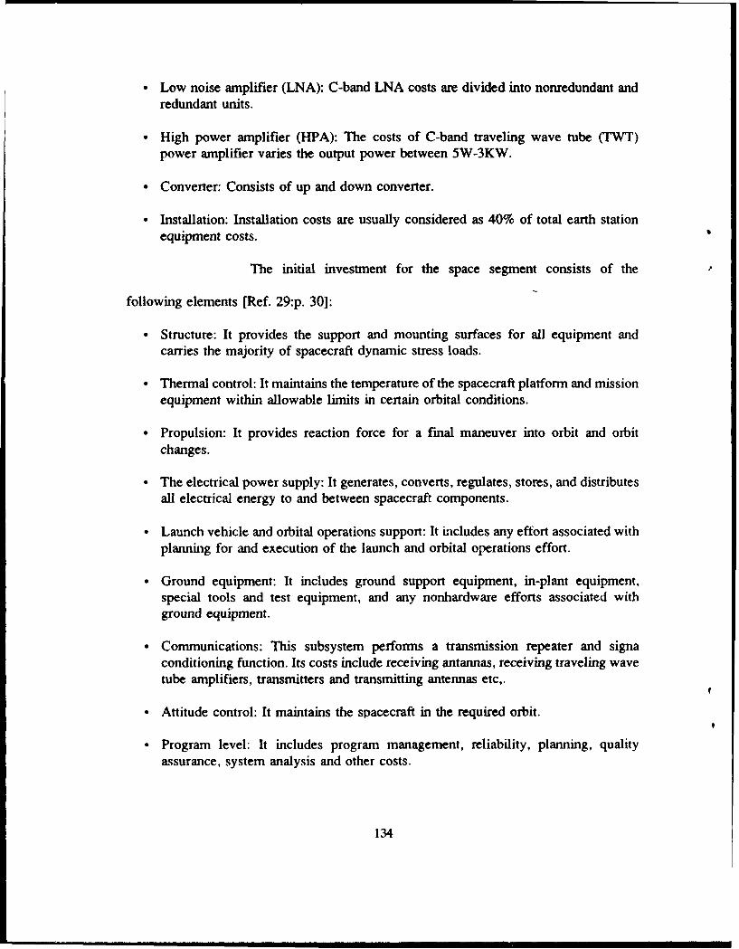
0 Low noise amplifier (LNA): C-band LNA costs are divided into nonredundant andredundant units.
0 High power amplifier (HPA): The costs of C-band traveling wave tube (TWT)power amplifier varies the output power between 5W-3KW.
* Converter: Consists of up and down converter.
• Installation: Installation costs are usually considered as 40% of total earth stationequipment costs.
The initial investment for the space segment consists of the
following elements [Ref. 29:p. 30]:
" Structure: It provides the support and mounting surfaces for all equipment andcarries the majority of spacecraft dynamic stress loads.
" Thermal control: It maintains the temperature of the spacecraft platform and missionequipment within allowable limits in certain orbital conditions.
" Propulsion: It provides reaction force for a final maneuver into orbit and orbitchanges.
" The electrical power supply: It generates, converts, regulates, stores, and distributesall electrical energy to and between spacecraft components.
• Launch vehicle and orbital operations support: It includes any effort associated withplanning for and execution of the launch and orbital operations effort.
• Ground equipment: It includes ground support equipment, in-plant equipment,special tools and test equipment, and any nonhardware efforts associated withground equipment.
* Communications: This subsystem performs a transmission repeater and signaconditioning function. Its costs include receiving antannas, receiving traveling wavetube amplifiers, transmitters and transmitting antennas etc,.
* Attitude control: It maintains the spacecraft in the required orbit.
" Program level: It includes program management, reliability, planning, qualityassurance, system analysis and other costs.
134
* Telemetry, tracking and command: It includes analog/digital converters, coders,digital electronics/computers, decoders, tape recorders etc,.
(2) Operation and Support cost
Operating costs include those costs for personnel pay and
allowances, equipment maintenance, logistics support and consumables. [Ref.29 p.31]
" Operations: This category includes cost associated with the use of the equipment.The cost incurred as a result of direct operation of the equipment and items actuallyconsumed in operation of the equipment are included in this category.
* Operating personnel: It covers the total cost of operating the system for the variousapplications.
" Maintenance facilities and personnel: The cost is based on the occupancy, utilities,and facility maintenance costs as prorated to the system.
" Supply support:It includes the cost of personnel, me ,rial, facilities and other directand indirect costs required to maintain and support the equipment and for systemduring the operational phase of its life-cycle.
The next and final step, which is not the underlying purpose of this
chapter, is to develop the satellite cost model based on the previously discussed cost
structure and cost elements. So someone else, who wants to be irvolved with satellite
communications systems cost evaluation and effectiveness, can use these basic concepts
and the data collected, and proceed to further analysis.
135

VII. CONCLUSIONS AND RECOMMENDATIONS
A. CONCLUSIONS
In this study, the attempt was made to show how telecommunications grew in the
last 30 years from its original state into a progressive and more self-reliant
telecommunication utility, including the satellites. This study is also intended to be a basic
study of satellite communications systems with emphasis on INMARSAT system.
A historical background and the technology of satellite communications have been
traced, through the basic concepts of military and international satellite communications,
leading up to the conceptualization of the INMARSAT system.
A brief background of satellite vulnerability and some basic concepts of the cost
evaluation and cost effectiveness analysis have been described in order to help someone
in the process of facing a jamming threat or choosing a satellite system, respectively.
We can summarize our most important conclusions as follows:
" Many new technologies in telecommunications have emerged during the late 1980sand early 1990s. The five most popular are satellites, digital microwave radio, fiberand coaxial cables, local distribution radio, and wire pairs. Some of the advantagesof satellite communications are wideband capa -;lity, distance-insensitive costs, andsuitability for mobile applicatio,,s.
" INMARSAT is an internationally-owned cooperative which provides mobilecommunications worldwide. Some of its services are direct dial telephone, telex,facsimile, and electronic mail for maritime applications, flight deck voice and data,automatic position and status reporting, and direct-dial passenger telephone foraircraft applications, position reporting, and two way data communications for landapplications.
136

" Satellite communication links using digital PN spread spectrum and FDMAtechniques are vulnerable to jamming and denying signals. Two types of interferingsignals were discussed, noise jammers and repeaters; each requires a specificgeometry to be used effectively. In the jamming of FDMA by noise jammers it isnecessary to overcome the signal power to increase the Bit Error Rate (BER). Inthis case there is a potential advantage of selective jamming, as the jammed usermay feel he is having system problems.
" For spread spectrum jamming, the disadvantage in overcoming the processing gainby brute force techniques is apparent.
* From the earliest years of satellite communications (moon and other passive satelliterelays) the effort was concentrated to improve the efficiency, reliability, andcapacity of the command and control channels. With each generation of satellitesthe communication capabilities have been increased, resulting in the developmentof military satellite systems for secure data transmission.
B. RECOMMENDATIONS
Based on the overall analysis attempted in this study, the following are
recommended as areas for further research:
* Cost-effectiveness methodology for evaluating and choosing a satellitecommunication system for the Hellenic Navy.
* Lease versus buy decision making for a satellite communications system based onINMARSAT.
137

LIST OF REFERENCES
1. Pritchard, W., Satellite Communication Systems Engineering, Prentice-Hall, Inc.,Englewood Cliffs, NJ, 1986.
2. Van Trees, H.L., Satellite Communications, IEEE, 1979.
3. Pelton, J.N. and Howkins, J., Satellite International, Stockton Press, New York, 1988.
4. Tri, Ha, Digital Satellite Communications, Prentice-Hall, Inc., Englewood Cliffs, NJ,1986.
5. Maral, G. and Bousquet, M., Satellite Communications Systems, Wiley, NY, 1986.
6. Bleazard, G.B., Introducing Satellite Communications, Halsted Press, New York, NY,1985.
7. Fthenakis, E, Manual of Satellite Communications, McGraw-Hill, Inc., U.S.A. 1984.
8. Dalgleish, D.I. An Introduction to Satellite Communications, Peter Peregrinus Ltd.,London 1989.
9. Morgan, W., Communications Satellite Handbook, John Wiley & Sons, Inc., N.Y,1989.
10. Operation Analysis Study Group, U.S. Naval Academy, Naval Operations Analysis,Naval Institute, Annapolis, Maryland, 1986.
11. Vormberg, F., " Military communication satellite programmes: U.S. satellite systems",Space Communication and Broadcasting, March 1986.
12. Vormberg, F., "Military communication satellite programmes: U.S. satellite systems",Space Communication and Broadcasting, June 1986.
13. Vormberg, F., "Military communication satellite programmes: U.S. satellite systems",Space Communication and Broadcasting, Sept 1986.
14. Economou, Athanasios, Navy Satellite Communications in the Hellenic environment,MS Thesis, Naval Postgraduate School, Monterey, California, June, 1988.
138

15. " LNTELSAT Satellites", Space Compmication and Broadcasting, November, 1986.
16. Lundberg, 0., The INMARSAT system and its future, Space Communication andBroadcasting, September, 1984.
17. Inaarsat, Facts about INMARSAT, June, 1990/FFCTS.
18. Chetty, P.R.K., Satellite Technology and its Applications, Tab Books Inc., Maryland,1988.
19. Inmarsat, INMARSAT-C, December, 1989/FSTD-C.
20. Inmarsat, The Global Maritime Distress and Safety System (GMDSS), December,1989/FGMDSS.
21. Inmarsat, Aeronautical Satellite Communications, January, 1990/AIRFAX.
22. Schleher, D., Introduction to Electronic Warfare, Artech House Inc., Norwood, 1986.
23. Meir, Bar-Tov, Satellite Communications Jamming Signals, Electrical EngineerThesis, Naval Postgraduate School, Monterey, California, September 1980.
24. Durch, W., National Interests and the Military use of space, Ballinger PublishingCompany, Cambridge, Massachusetts 1984.
25. Wilding, T., " Gateway to the sea", Ocean Voice, July 1985.
26. Hellenic Telecommunications Organization, 927.38/405576, Information onINMARSAT, December 1990.
27. Mansfield, E., Microeconomic: Theory and Applications, W. Norton and Company,1985.
28. Schworer, W.J., Nationwide Mobile Communication Systems, MS Thesis, NavalPostgraduate School, Monterey, California, June 1990.
29. Hwang, Tae Kyun, Cost-Effectiveness Methodology for evaluating KoreanInternational Communication System Alternatives, MS Thesis, Naval Postgraduate School,Monterey, California, March 1987.
30. Pangalos. Panagiotis, Private Telecommunications Systems: A Systems Approach, MSThesis, Naval Postgraduate School, Monterey, California, September 1990.
139

BIBLIOGRAPHY
1. E.W. Ashford, " INTELSAT Satellites", Space Communication and Broadcasting,November, 1986.
2. Bleazard, G.B., Introducing Satellite Communications, Halsted Press, New York, NY,1985.
3. Dalgleish, D.I., An Introduction to Satellite Communications Peter Peregrinus Ltd.,London, 1989.
4. Douglas, R.L., Satellite Communications Technologv, Prentice-Hall Inc., EnglewoodCliffs, 1988.
5. Durch, W., National Interests and the Military use of space, Ballinger PublishingCompany, Cambridge, Massachusetts, 1984.
6. Economou, Athanasios, Navy Satellite Communications in the Hellenic environment,MS Thesis, Naval Postgraduate School, Monterey, California, June, 1988.
7. Fthenakis, E., Manual of Satellite Communications, McGraw-Hill, Inc., U.S.A, 1984.
8. Hellenic Telecommunications Organization, 927.38/405576, Information onINMARSAT, December 1990.
9. Hwang, Tae Kyun. Cost-Effectiveness Methodology for evaluating Korean InternationalCommunication System Alternatives, MS Thesis, Naval Postgraduate School, Monterey,California, March 1987.
10. Inmarsat, Facts about INMARSAT, June, 1990/FFCTS.
11. Inmarsat, The Global Maritime Distress and Safety System (GMDSS), December,1989/FGMDSS.
12. Inmarsat, Aeronautical Satellite Communications, January, 1990/AIRFAX.
13. Inmarsat, INMARSAT-C, December, 1989/FSTD-C.
14. Jarett, D., Satellite Communications:Future Systems, TRW, Inc., Redondo Beach,California. 1976.
140

15. Lundberg, 0., " The INMARSAT system and its future", Space Communication andBroadcasting, September, 1984.
16. Mansfield, E., Microeconomic: Theory and Applications, W. Norton and Company,1985.
17. Maral, G. and Bousquet, M., Satellite Communications Systems, Wiley, NY, 1986.
18. Martin, J., Communications Satellite Systems, Prentice-Hall Inc., Englewood Cliffs,1978.
19. Meir, Bar-Toy, Satellite Communications Jamming Signals, Electrical EngineerThesis, Naval Postgraduate School, Monterey, California, September 1980.
20. Morgan, W., Communications Satellite Handbook, John Wiley & Sons, Inc., N.Y,1989.
21. Operation Analysis Study Group, U.S. Naval Academy, Naval Operations Analysis,Naval Institute, Annapolis, Maryland, 1986.
22. Pangalos, Panagiotis, Private Telecommunications Systems: A Systems Approach, MSThesis, Naval Postgraduate School, Monterey, California, September 1990.
23. Pelton, J.N. and Howkins, J., Satellite International, Stockton Press, New York, 1988.
24. Pritchard, W., Satellite Communication Systems Engineering, Prentice-Hall, Inc.,Englewood Cliffs, NJ, 1986.
25. Schleher, D., Introduction to Electronic Warfare, Artech House Inc., Norwood, 1986.
26. Schworer, W.J., Nationwide Mobile Cormnunication Systems, MS Thesis, NavalPostgraduate School, Monterey, California, June 1990.
27. Seiler, K., Introduction to Systems Cost-Effectiveness, Wiley-Interscience, 1968.
28. Tri, Ha, Digital Satellite Communications, Prentice-Hall, Inc., Englewood Cliffs, NJ,1986.
29. Van Trees, H.L., Satellite Communications, IEEE, 1979.
30. Vormberg, F., " Military communication satellite programmes: U.S. satellite systems".Space Communication and Broadcasting, March 1986.
141

31. Vormberg, F., "Military communication satellite programmes: U.S. satellite systems",Space Communication and Broadcasting, June 1986.
32. Vormberg, F., "Military communication satellite programmes: U.S. satellite systems",Space Communication and Broadcasting, Sept 1986.
33. Wilding, T., " Gateway to the sea", Ocean Voice, July 1985.
142
INITIAL DISTRBUTION LIST
No. Copies1. Defense Technical Information Center 2
Cameron StationAlexandria, VA 22304-6145
2. Library, Code 52 2Naval Postgraduate SchoolMonterey, CA 93943-5002
3. Dr. Dan C. Boger, Code AS/Bo 2Department of Administrative SciencesNaval Postgraduate SchoolMonterey, CA 93943-5002
4. Dr. William R. Gates, Code AS/GtDepartment of Administrative SciencesNaval Postgraduate SchoolMonterey, CA 93943-5002
5. Embassy of Greece 5Naval Attache2228 Massachusetts Ave., N.W.Washington, D.C. 20008
6. Aristides Fasoulas 3Pindou 106Papagou 15669Athens, Greece
143