Naval Postgraduate School - apps.dtic.mil · Liner Flow and Streamline Coordinates ----- 46 7....
66
United States Naval Postgraduate School THESIS h A NEW OPTIMIZATION THEORY FOR THE END-INITIATED LINEAR SHAPED CHARGE by ADE C I -n George Elliott Brown, Jr. Reproduced by the ?t 2 19(0 CLEARINGHOUSE 1Ei\ _or Feoderal Scientific & Technical Information Springfield Va 22151 LI October 1969 T/ doww~t ha been apprved 604 pubU4 a- tme ad 6aL; i& d" dlbbton U~ WiJirUe
Transcript of Naval Postgraduate School - apps.dtic.mil · Liner Flow and Streamline Coordinates ----- 46 7....

United StatesNaval Postgraduate School
THESIS
h A NEW OPTIMIZATION THEORY FOR THE
END-INITIATED LINEAR SHAPED CHARGE
by ADE CI -n
George Elliott Brown, Jr.Reproduced by the ?t 2 19(0CLEARINGHOUSE 1Ei\_or Feoderal Scientific & TechnicalInformation Springfield Va 22151 LIOctober 1969
T/ doww~t ha been apprved 604 pubU4 a-tme ad 6aL; i& d" dlbbton U~ WiJirUe

A New Optimization Theory for the
End-Initiated Linear Shaped Charge
by
George Elliott Brown, Jr.Lieutenant, United States NavyB.S.U.S., Naval Academy, 1962
Submitted in partial fulfillment of therequirements for the degree of
MASTER OF SCIENCE IN AERONAUTICAL ENGINEERING
from the
NAVAL POSTGRADUATE SCHOOLOctober 1969
P Author -
Approved by:Thesis Advisor
Rairman, Depar ment of Aeronautics
Academic Dean

ABSTRACT
An exposition of the two existing analytical approaches
to the end-initiated linear shaped charge is made. After
a theory is put forth relating optimization to increased
energy transfer at increased standoff distances, this effect
is linked to the dispersive rature of the jet mass. An
analytical design approach is then formulated that combines
elements of both existing models. The object of this ap-
proach is to integrate experimental data into a mathematic-
ally definitive analysis. A theoretical link is then
developed between the dispersive nature of the jet and the
design input parameters, thus completing the optimization
model.
2

TABLE OF CONTENTS
I. INTRODUCTION -------------------------------------- 11
II. THE END-INITIATED LINEAR SHAPED CHARGE ----------- 12
III. THEORETICAL BACKGROUND --------------------------- 15
IV. APPROACH TO OPTIMIZATION THEORY ------------------ 25
V. OPTIMIZATION THEORY ------------------------------ 28
VI. CONCLUSION --------------------------------------- 37
APPENDIX A: FEASIBILITY STUDY OF EXPERIMENTALFUNCTION ANALYSIS ------------------------- 38
LIST OF REFERENCES ------------------------------------- 64
INITIAL DISTRIBUTION LIST ------------------------------ 66
FORM DD 1473 ------------------------------------------- 67
3

LIST OF ILLUSTRATIONS
1. Simple Conceptual Model of L.S.C. ------------------ 43
2. Detonation Process in Simple L.S.C. ---------------- 43
3. Representative Warhead Configurationusing L.S.C. Principle ------------------------- 44
4. Fixed and Moving Coordinate Systems -------------- 5
5. Coordinates in Cross-Section Coincidentwith Detonation Front -------------------------- 45
6. Liner Flow and Streamline Coordinates ----------- 46
7. Separation of the Liner Streamline Dueto Jet and Slug Streamlines -------------------- 47
8. Three-Dimensional Kinematics of Impact ----------- 48
9. Formation of the Jet and Slug along a FiniteElement of the Curve of Impact ----------------- 49
10. Conversion to Inertial Velocities ---------------- 50I
11. Sequential Development of Jet and Slug ----------- 51
12. Constant Angle Idealized Collapse Case ----------- 52
13. Balance Between Mass and Kinetic EnergyDivision for the Idealized Collapse Case -------- 52
14. Displacement History Across the Vane ------------- 53
15. Shock Wave Interaction Behind theDetonation Front ------------------------------- 53
16. Liner Displacement as Affected byLongitudinal Acceleration Variation(Approximating Function) ----------------------- 54
17. Summation of Velocity Vectors Providedby Sewell's Analysis --------------------------- 54
18. Penetration - Standoff Curves for VariousValues of Jet Break-up Time (ConicalShaped Charge) --------------------------------- 55
19. Hole Volume - Standoff Curves for VariousValues of Jet Break-up Time (ConicalShaped Charge) pjEng -g BOX ---------------- 56
5

20. Loci of Possible Velocity Solutions -------------- 57
21. Geometry of Inertial Velocity Solutions ---------- 58
22. Cross-Section of Recovered Slug fromL.S.C. of Mild Steel --------------------------- 59
23. General Shape of the Convoluted Surfacesfor the Case of a Nearly PlaneDetonation Wave -------------------------------- 59
24. Framing Camera Record of the Detonationof the Test Model ------------------------------ 60
25. Tracing of Liner Free Surface DisplacementCurves (Typical) --------------------------------- 62
26. Expanded Plot used in Location of FreeSurface Discontinuities (Typical) --------------- 63
6

1
I
TABLE OF SYMBOLS
VD Velocity of the detonation wavefrontJVD
XYZ Inertia! coordinate system
n,l ,Coordinate system that is translating withthe detonation front
n Mirrored translating coordinates that define' ' the "other" liner wall
t time measured from initiation of charge
t time for a fixed point in the charge, measuredfrom passage of detonation wave
T the total time required for the detonationwave to traverse the charge length L
8 half the included angle of the "V" trough
0 half the included angle of the star point
S the label for a general streamline
S the label for the streamline symmetric to S
C the label for the curve of impact*
P the point of impact of S and S
C, C coordinates of the impact curve C
clzc coordinates of the impact curve C
KE. (KESL Relative Kinetic Energy of the jet (slug)
Mj (MSL) Relative Mass of the jet (slug)
L Length of Charge
V. (Vs1 ) Velocity of the jet (slug) particle in the
translating frame
Vj (VSL) Inertial velocity of the jet (slug) particle
Vp Projection of incident liner velocity in theplane of symmetry
7

U component of VP in direction
w Pcomponent of v in Z direction*
i included angle of S and Sp
p angle between VP and E axis
a C angle between local tangent to C and E axis
a spray angle associated with a particularstreamline
IYISL)J the area mass density of the jet (slug) ata point
tr Reverberation time or time required for thestress wave to traverse twice the liner width
T R Relief time - a constant accounting for thedetonation front curvature and release wave
velocity for a particular charge configuration
ML Mass of the liner
coordinate measured with reverse sign alongn from a zero at n max
8

ACKNOWLEDGEMENTS
The author wishes to express his grateful thanks to
Professor J. E. Sinclair, his advisor, to Dr. R. G. S.
Sewell who was a constant source of encouragement and to
Asst. Professor D. W. Netzer for his timely advice.
I
F
V!9

1. INTRODUCTION
The end-initiated linear shaped charge is a fairly
recent application in the warheads field. Essentially it
is a refinement of the basic phenomenon of shaped or cavity
charges first discovered by Monroe in 1888. Although the
same principle of end-wave initiation is used in linear
metal cutting charges for such applications as stage separ-
ation in rocketry, nowhere is the efficiency of the
mechanism as important as in the warhead application. The
immense cost of maintaining and exercising today-s delivery
systems, measured in dollar value or by other means,
dictates great marginal utility for any improvement in
warhead effectiveness. Such an improvement in effectiveness
is difficult to measure and usually not a function of size.
It is best described as achievement of a better compromise.
The trend in recent years has been to match specific type
targets to specially designed warheads such as the linear
shaped charge but this entails an undesirable loss of
employment flexibility. An improvement in the effective-
ness of this type of warhead therefore must pertain to all
types of targets and must increase the effective radius in
order to cut down on. the number of weapons that must be
delivered to the target area to insure it's destruction.
PRECEDING PAGE BL.AKIA II

II. THE END-INITIATED LINEAR SHAPED CHARGE
The basic mechanism of the end-initiated linear shaped
charge (hereinafter referred to simply as LSC) is so complex
as to defeat any purely mathematical approach to it's
description. Moreover, its action is so catastrophic in
nature that it obviates many of the empirical analysis tech-
niques used to unlock the secrets of other pressure-time
dependent phenomena. A much simplified description of the
basic mechanism of jet and slug formation is a necessary
background for understanding of the analytical model of the
LSC.
The simplest configuration of the LSC is that of Figure
1, a long column of solid explosive which has had a "V"
notch inscribed in one of it's surfaces. The interior of
this notch is lined with a layer of metal such as copper,
aluminum, or mild steel. In operation the explosive column
is initiated at one end resulting in the steady-state
detonation condition where the detonation wave ( a planar
wavefront perpendicular to the charge axis in our simple
case) is propagating down the column axis at a constant
detonation velocity VD. The peak pressure pulse whose
leading edge is coincident with (indeed the triggering
mechanism of) the detonation wave begins to deform the metal
liner upon its passage. As the two sides of the "V" are
"squeezed" together, symmetric elements of each wall collide
and separate such that the liner as a whole is divided into
12

two fairly distinct masses, both of which propagate away
from the charge axis in the longitudinal plane of symmetry
of the "V" notch. These masses are commonly termed the
jet and the slug (Figure 23. The jet consists of a thin
sheet of molten liner material with particle velocities on
the order of 15,000 ft./sec., while the slug tends to be
less discrete in the propagation plane and possesses par-
ticle velocities in the 5,000 ft./sec. range.
The damage-producing potential of even a small mass of
material at jet velocities is quite evident, but the jet and
slug have another characteristic that is very important in
their ability to cut metal or to retain their energy over
moderate distances. The jet is dispersive in nature. That
is, the leading edge particles of the jet are possessed of
initial velocities considerably in excess of those of the
trailing edge. Thus, the jet sheet stretches longitudinally
(radially with respect to the original charge axis) as it
propagates. Conversely, the slug's leading edge has a lower
initial velocity than its trailing edge and thus, it tends
to coalesce as it propagates. These important properties
will be examined in greater detail in Section IV.
The included angle of the notch (20) must, of course,
lie between 0* and 1800. We see in Figure 3, however, that
when we combine several charges into the cylindrical con-
tainer required of most warhead applications, we further
restrict the "V" angle. In the illustrated case of eight
propagation planes, a e value of 22 would leave no
13
interior volume for the required explosive. For ease in
understanding, this configuration with 20 = 1200, and the
star point angle 20 = 750 is used as the point of departure
throughout this thesis.
14

III. THEORETICAL BACKGROUND
There are in existence two analytical approaches to the
end-initiated linear shaped charge. By far the most
rigorous from a mathematical viewpoint is the analytical
model of M. A. Garcia contained in Reference 2. This model
treats the LSC mechanism in detail through jet and slug
formation. The other extant formulation is that of Robert
G. S. Sewell [Reference 1]. Here a building block approach
is used in an effort to separate the effects of the sig-
nificant parameters and a great deal more correlation with
empirical results is made. Both of these treatments consti-
tute the foundation of this thesis. In the interests of
continuity, the terminology of the more mathematical
Reference 2 will be used wherever possible. Following
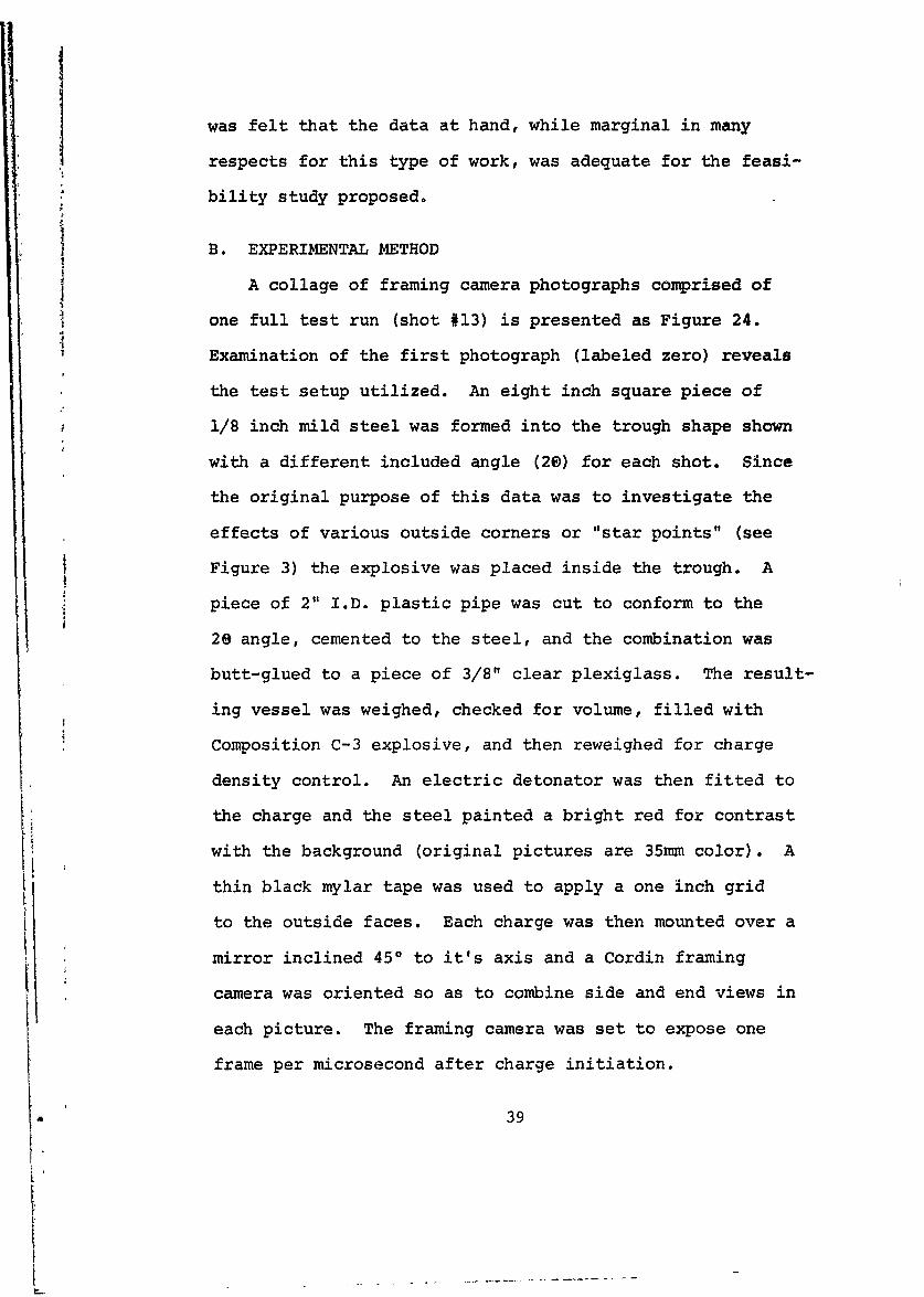
Garcia, then, an inertial coordinate frame, (X,Y,Z in Fig.4)
fixed to the charge which in turn is fixed in space estab-
lished. The X axis is coincident with the trough apex,
with the origin at the initiator end, and the X-Z plane
defining the plane of symmetry of the trough.
Two important basic assumptions, germane to the entire
analysis, are now made.
Assumption #1. The detonation wavefront propagates
through the explosive longitudinally at a constant velocity.
End effects are neglected and only steady-state jetting is
considered. This assumption holds throughout this thesis.
15

Assumption #2. The detonation wavefront is contained
in a plane perpendicular to the charge axis and moving in
the positive X direction at velocity VD. This assumption
holds throughout the analysis of Garcia, and in part of
Sewell's study, but is further examined in Section V of
this thesis. Armed with these assumptions, a moving coor-
dinate frame (n,i, ) whose origin at any one time is de-
fined by the intersection of the detonation front and the
X axis is defined. The axis is coincident with the X
axis, but directed back toward the origin of the inertial
X,Y,Z system. The n-? plane defines the detonation front
with the n axis lying in the plane of one liner wall
[Figures 4 and 5).
Assumption #3. The solid metal liner is treated as
an incompressible, inviscid fluid with no internal stress
and in a steady flow state, the flow velocity being a con-
stant VD to an observer riding the n,4, coordinate frame.
Garcia's basis for this is the extreme pressure (on the
order of 200 to 300 kilobars) and temperatures existing
behind the blast wave, as well as the detonation velocity
which is in the neighborhood of 25,000 ft./sec. for a
representative explosive composition. This assumption is
also re-examined in Section V.
Assumption #4. The pressure forces behind the deforming
liner act along the normal to the n- plane and the devia-
tion of the deforming liner in the direc tion is small.
16

This assumption also receives more attention later in the
development.
Assumption #5. Liner particles do not change their
n values until they reach the curve of impact C in the
plane of symmetry. Thus, each n value defines a stream-
line (S) continuous in both the undisturbed and deforming
portions of the liner. Now another coordinate system* *
(n,I,E, the mirror image of nl, ) can be introduced to*
define symmetrical streamlines (S) in the other wall.
It can now be seen in Figure 6 that "fluid" particles of,
values n=n and X=X travel respectively along streamlines*
S and S to eventual collision at a point P on the curve
of impact in the plane of symmetry.
Assumption #6. Kinetic energy, total mass, and momentum
in the plane of symmetry are conserved in the particle
impacts at point P. Thus, due to symmetry and this lossless
assumption, each particle of liner reacts as if it were
impacting a solid frictionless wall coincident with the
plane of symmetry.
Proceeding on the basis of the above assumptions, it
can be determined that, upon reaching the curve of impact,
the liner particles separate into jet and slug through a
collision process entirely within the plane of symmetry.
Thus, two dimensional vector equations can be written in
the symmetry plane for the components of velocity
17

(1) V = U e + Zj e z
where u=
(2) VSL USL e + ZSL eZ
These four velocity components, together with the two area
mass densities at the curve of impact constitute the six
unknowns of a complete description of the collision process.
The area mass densities pj and PSL are defined by:
(3) dmji = PidZd and dmSL = 11SL dZd
The principles of conservation of kinetic energy, mass, and
momentum introduced in assumption #6 provide five constraint
equations, necessitating one further assumption. The fol-
lowing assumption, introduced by Garcia to render the
problem determinate, is critical to the entire mathematical
analysis.
Assumption #7. The streamline of the jet and slug form
symmetrically with respect to the direction of flow of the
liner streamline as projected in the plane of symmetry
before impact. Figure 7, where Vp is the component of the
incident liner streamline in the plane of symmetry, depicts
this geometry.
As a result of Assumption #7 and the conservation rela-
tions Garcia proves that the spray angle a is identically
equal to the angle of incidence between the incoming line
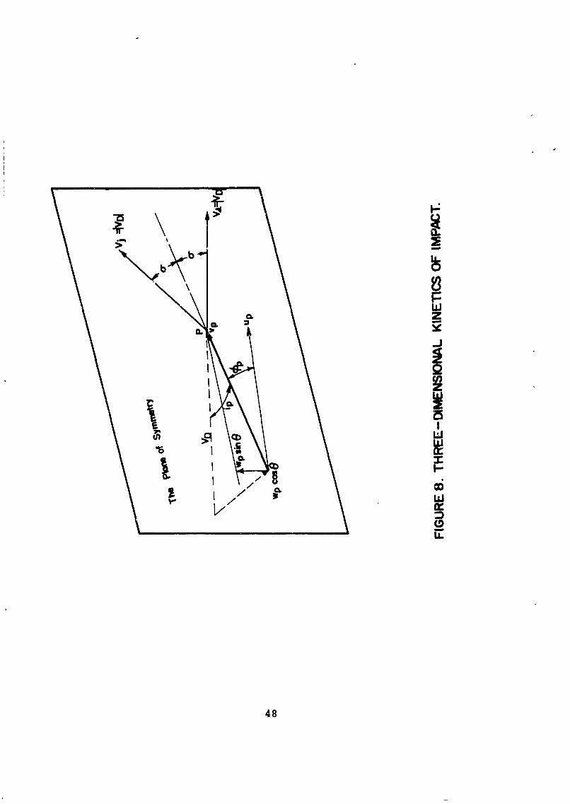
streamline and the plane of symmetry (2a ip) [Figure 8].
18

This is an important concept and it is brought up again in
Section V. It is also important to note that the slope of
the curve of impact at any point P must exceed the slope of
the incoming liner streamline projection in the symmetry
plane. The flow geometry resulting from this consideration
is portrayed in Figure 9.
The jet and slug velocities in the inertial frame may
now be found by vector addition of the detonation wave
velocity as depicted in Figure 10. Here, in the simple
view for one liner streamline (one constant value of n and
some characteristics noted experimentally show up.
The jet exhibits a much greater velocity and about double
the lead angle as compared to the slug material. Garcia
goes on to develop the mathematical basis for the mapping
of lines of constant n in the liner into their respectivet
positions in the jet and the slug at any time L by means
of a Jacobian of transformation*. An example of the mapping
for his most general case is presented as Figure 11.
The analytical model of Garcia then provides a precise
means whereby, given the charge geometry, the detonation
velocity and the profile of the pressure pulse, all of the
pertinent jet and slug characteristics can be found. This
is subject only to the assumptions delineated above. Al-
though this model is a profound instrument for understanding
the physics of the LSC, the fact that it hinges on intimate
*Here T is the time required for the detonation wave to
traverse the entire charge.
19

knowledge of the pressure parameter renders it inadequate
of itself for optimization techniques. Instrumentation
capable of describing the extremes of the pressure pulse
delivered by the blast wave in the explosive as a function
of the charge surface coordinates is not likely to be
available in the near future. Some means of equating charge
performance with measurable parameters is essential to any
charge effectiveness improvement program.
Considerable insight in this direction is provided by
the pioneering work of R.G.S. Sewell contained in Reference
1. Here the method is to start with a simple two-dimensional
description of jet and slug formation, and then to succes-
sively introduce the complexities necessary for a complete
description, each couched in two-dimensional terms. A brief
synopsis of this work is pertinent here. Sewell's develop-
ment takes it's genesis in the case of two plates or liner
sides being propelled along their respective normals ( and
* axes) at a constant velocity ( = * const.). Thus,
as shown in Figure 12, the incidence angle 0 is maintained
as a constant. This, in fact, embodies the essence of
Assumption #4 above. Making the assumption of conservation
of kinetic energy, mass, and momentum (#6 above) and, in
addition, applying the incompressible inviscid fluid
assumption of #3, but only at the point of collisions and
beyond, the following relationships result:
(4) Mj= ML (1 - cos 0)
20

1(5) M = ML (1 + cos 8)
(6) KE -M 1 2 + Cos e)
(7) .* _ * 2 Cos )
~SL 4ML ~(-cS~
where KE = Kinetic energy per unit mass and ; = z*, andML = mass of the liner
The balance between mass and kinetic energy of the slug
and jet evident in the above equations is further amplified
in Figure 13, a plot of 1 ± cos 6. In actuality only a
portion of this plot is of practical interest, e valuesless than about 300 and greater than 900 (flat plate) having
no meaning in the analysis. Coincident with the mass and
energy relations, the jet and slug velocities can similarly
be expressed as functions of 6 for the idealized case at
hand.
(8) V. = % (csc a + cot 6)
(9) VSL= (csc 6 - cot 6)
Using a value predicted by the Stern flat sandwich
equations (References 3 and 4), Sewell shows that the above
velocity equations correlate nicely with measured values
(at the leading edge of the jet). The jet leading edge
velocity is formed by collisions at the apex of the "V"
trough, however, here the constant angle assumption is
essentially met. The mass (and thus, also energy) balance
a 21

observed empirically does not, however, agree when taken for
the whole charge. Sewell's next step introduces the effect
of the variation in acceleration history across the wave,
(from apex of trough to its edge). Taking a mean of the
stepwise velocity functions caused by the reverberating
shock wave in the plate and also accounting for the propa-
gation of the release wave in the explosive products from
the edge Sewell describes the velocity as:
(10) = (1 -et/tr)
where tr is the reverberation time, or the time required
for the stress wave to traverse twice the liner thickness,
and o is again calculated by the Gurney-Stern formulas.
Signifying n measured in a negative direction from a zero
at the edge of the vane by n, Sewell's function for dis-
placement becomes:
(11) (,t) = R ( - et/tr)dt + (t- TR)(l - e Rr)0
where TR, the relief time, is a correction factor for the
release wave velocity and the curvature of the detonation
front. Here the integral accounts for displacement during
acceleration and the second term represents propagation at
the constant initial velocity. Solutions to Equation 11
for various times after passage of the detonation front are
presented in Figure 14. The figures are for a charge where
nMAx = 3 inches. Here the dotted line corresponds to the
22

!0
plane of symmetry for an angle e = 60 . The solution
times are, of course, equivalent to various values of
coordinate E in the translating frame. The effect of
this displacement profile on the effective value of the
trough angle (at successive E values on the curve of im-
pact) is accentuated by the labeled tangents.
Sewell next accounts for the acceleration history
longitudinally along the vane behind the detonation wave
front. Here, again, the effect of stress wave reverbera-
tion makes itself felt on the displacement profile, but
the release wave is not a factor. Figure 15 depicts the
stress wave effect on the liner with area CDE represent-
ing a Prandtl-Meyer expansion. Sewell defines the
instantaneous angle assumed by the disturbed liner with
respect to its original position (here designated 'W) as
a function of time. Again the function is a continuous
approximation to the discontinuous function resulting
from the reverberation effect. Here:
_t/t r(12) w(t) = o(1- e - / r
where w is the final (maximum) angle assumed. This func-
tion is depicted in Figure 16 and, assuming a constant VD,
a simple re-labeling of the axes transforms the curve into
a plot of C versus E (longitudinal acceleration effect
only). Sewell then enters this effect into his model by
tipping the previous solution through the angle wo. Note
that this neglects the effect of curvature of the detonation
23

wavefron. A velocity vector summation with representative
midrange values for a charge similar to that depicted in
Figure 3 is then performed [Figure 17]. These values
correspond quite well with experimentally observed values
of lead angle and mean velocity.
Comparison of Sewell's approach to the Garcia model
yields several important differences. It is most signifi-
cant that Sewell does not rely on the ideal fluid assumption
(#3) until the impact that forms the jet and slug takes
place. Garcia on the other hand treats the liner as
inviscid and incompressible throughout its deformation by
an impulsive overpressure and subsequent relief pressure.
Further, the curvature of the detonation wavefront, only
partly treated by Sewell, introduces extreme mathematical
complexity into the Garcia model. The normal force assump-
tion (#4) is common to both approaches as it is embodied
in the Gurney and Sterne formulas used by Sewell. While
Garcia's treatment is unique in providing a definable par-
ticle by particle analysis rather than a midrange value, it
suffers from the dependence on experimentally unattainable
pressure measurements as previously mentioned. Sewell's
approach, on the other hand, furnishes an appealing dis-
section of the three-dimensional problem into two-dimensional
displacement functions that show promise of experimental
verification. In short, elements of both analyses are
necessary for any attempt at charge performance improvement.
24

IV. APPROACH TO OPTIMIZATION THEORY
The first consideration in any optimization procedure
must, of course, be some definition of its goals, pre-
ferably a direct measure of degree of optimality. Un-
fortunately the uses to which the shaped charge warhead is
put, the conditions under which it is expected to perform
it's task, and the variables involved in it's operation are
far too diverse to allow any such precise measurement func-
tion. A great deal of attention has been given the target
effects of shaped charge jets in recent years, particularly
by the Ballistics Research Laboratory in regard to conical
shaped charges. Some of the reports on this work, notably
by DiPersio, Simon, and Merindino are listed as References
5 through 8. References 9 through 13 pertain more directly
to the end-initiated LSC which has received emphasis at
the Naval Weapons Center.
The original emphasis on shaped charge use was the
localized defeat of armor plate in point attack by conical
charges. The more recent use of the LSC reflects a shift
in emphasis, utilizing the basic damage mechanism to inflict
linear damage on softer metal targets, particularly steel
and concrete bridge structures. Recently tactical commanders
have stressed the need for weapons that afford as great a
choice of target as possible. They stress this need for
flexibility particularly in the case of air delivered
25

weapons. References 9, 11, and 13 then reflect effective-
ness studies of an LSC warhead against targets such as
missile sites, truck parks, and gun emplacements as well
as bridge structures.
An optimization procedure, therefore, must lead to an
increase in the warhead's effectiveness against the general
target - "softer" for the most part and, significantiy,
more widely dispersed. This must be accomplished without
degrading it's performance against girders and trusses at
short range. A basic characteristic of shaped charge action
must be sought, the control of which will provide increased
weapon effectiveness against targets at greater "standoff"
distances. That characteristic is the dispersive nature of
the jet material mentioned previously. The selection of
dispersion as the subject for optimization wIll now be
justified.
Most of the studies made on the effectiveness of shaped
charges pertain to the use of conical charges against armor
targets. References 5 and 6 by DiPersio, et. al., show
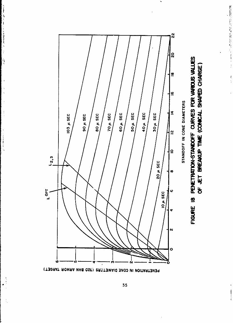
that penetration effects increase with increased standoff
distance up to an optimum value and then drop off signifi-
cantly. By means of flash radiographs (not reproducible
here) they were able to correlate this optimum standoff
distance with the maximum jet length before particulation*.
As stated in Section II the dispersive velocity gradient
Particulation refers to that point where the jet
simultaneously fragments along its entire length.
26

*1
from tip to tail of the jet causes the jet to stretch
longitudinally during propagation. This continues until
the limit of cohesion of the jet material is reached at
* which time the jet particulates into a string of elements.
These elements are of fairly uniform lengths of the order
of 2 - 5 times jet width at particulation and continue to
lengthen thereafter. DiPersio and Simon's discovery that
this particulation is instantaneous along the entire jet
length is particularly significant. It led to their
relation of penetration to jet break-up time depicted in
Figure 18. Figure 19, also from Reference 7, relates hole
volume to jet break-up time. In essence this figure shows
that reducing the dispersive nature of the jet which, in
turn, produces greater values of jet break-up time, results
in a quantum jump in the efficiency of energy transfer
from the charge to the target at all standoff ranges.
There is a limitation imposed, however, in that elimi-
nation of the dispersive gradient of the jet altogether
would eliminate the mechanism by which the jet cuts metal
targets. The gradient allows time for a jet particle to
plastically react with a portion of the target mass by
exceeding its dynamic yield strength and then flow away from
the point of impingement before the arrival of the next jet
particle. For this reason the retention of a small, but
controlled gradient is probably advisable.
27

V. OPTIMIZATION THEORY
Armed with a specific charge parameter, namely dis-
persion, the control of which will produce the desired
targeting effects, a basis for LSC optimization has been
established. It remains to identify the physical aspects
of the LSC that give birth to the dispersive effect of the
jet and to link them to variables measurable by experi-
mental means. Finally, one or more parameters that can
control the dispersion and yet are capable of manipulation
by the warhead designer must be isolated.
Some of the salient differences between the theories
of Garcia and Sewell were highlighted at the end of
Section III. It becomes apparent that reconciliation of
the combined two-dimensional approach of Sewell with the
translating reference frame and analytical description
of impact kinetics of Garcia's description obviates many
of their respective drawbacks to our purpose. The means
of empirical verification and, if necessary, function
description is introduced into Garcia's analysis by means
of the longitudinal and lateral displacement profiles of
Sewell's approach. In an attempt to probe the feasibility
of such experimental identification of the displacement
functions, and to gain insight into the magnitude of
difference between the two original theories, a limited
investigation was conducted. This investigation is outlined
in Appendix A. The discontinuities in displacement and
28

velocity predicted at points C and H-J on Figure 15 were
identifiable only on a statistical basis, but this is
probably attributable to the quality of the data which
was not generated for this particular investigation. The
fact that a steady-state velocity is reached after approx-
imately two reverberation times was verified. It is felt
that careful analysis of experimental work done specifical-
ly for the purpose could successfully identify the required
two-dimensional functional relationships.
The experimental work of Appendix A leads logically to
a possible means of relating empirically definable functions
to a theoretical formulation of shaped charge physics. A
more sophisticated system than the one used in Appendix A
should be able to define the acceleration history across
the vane by description of the instantaneous displacement
profile at various constant values of . This will require
a larger scale model initiated by a plane wave generator
and probably utilization of flash radiography or betagraphy.
The point to such a test program would be to isolate and
mathematically describe the following physical functions:
1.) displacement function in the 4- plane (Appendix A)
2.) displacement function in the n-r plane
To these would be added the following functions over which
the LSC designer has some control:
3.) detonation wave shape as a function in the n-C plane
4.) half angle of notch (8)
i

Another design variable that could be added later if
necessary is:
5.) shape of liner sides in the n- plane
The above procedure reduces the problem of defining the
convoluted surface, or the complex shape that is taken on
by the liner between the detonation wavefront and the plane
of symmetry, to a problem in solid geometry well within the
capabilities of a modern third-generation computer. What
remains is to define a parametric link between the dispersion
of the jet elements and some aspect of this convoluted sur-
face. We are led to a re-examination of the kinetics of
impact in the plane of symmetry.
Garcia's critical assumption in this impact process
(assumption #7) was that the jet and the slug form sym-
metrically with respect to the direction of flow of the
liner streamline as projected in the plane of symmetry
before impact. This leads to a prediction of equal amounts
of liner mass going into the jet and slug, a conclusion
that is not collaborated by experimental evidence. As
pointed out by Garcia himself, unbalanced mass distributions
are predicted only by streamline separations symmetrical to
a line having steeper or shallower inclination than the
projected streamline.
If we examine the conversion of the jet and slug
velocities to the inertial frame, we see in Figure 20 that
the locus of possible solutions to these inertial velocities
30
j

lie on a circle of radius VD that is equivalent to that in
the translating frame. Removing Garcia's restriction that
the symmetrical streamline division be defined by V , we
will replace V by an arbitrary direction that might be
VpI the local tangent to the curve of impact, or some
unknown combination thereof. Continuing to denote the
arbitrary vector's slope by * as we did for V we combine
the geometry in Figuri 21. Since the inertial velocities
form chords of the circular locus, we can express them as
functions of the subtended angle. Using the cap (^) to
denote inertial quantities,
(13) V. = 2 VD sin (0)D 2
(14) V= 2 V sin ( )SL r) 2
It has long been known, as noted previously, that ele-
ments of the jet exhibit a dispersive velocity gradient, and
that the leading edge of the jet is formed at the apex of
the notch. From these two facts it follows that:
(15) (V) > (V.)(V3) j +An
Combining equations 13 and 15 leads to:
(16) (V sin (') > (VD) sinD6 2 n 2+An n+An
Any variation of VD as a function of n would have to be
due to variations in the velocity in the 1 (and *) direc-
tions. These variations are reflected in the convoluted
31

surface shape and, given the detonation velocity on the
order of 25,000 ft./sec., are relatively minor. There
doesn't seem to be much basis for a significant variation
of VD with n and this then leads to the conclusion that:
(17) (+o) n > n+An
Proceeding with an analagous development for the slug
uncovers a discrepancy in the existing theory. Eichelberger,
Pugh, and Rostoker (References 14 and 15) in their work with
conical shaped charges uncovered the fact that there is a
continuity in jet and slug formation in that the last
formed jet element travels at the same speed as the last
formed slug elements. A close examination of Garcia's work
reveals that he assumes that both the jet and slug are
dispersive. He further bases his work on the assumption
that the trailing edge of the slug is formed at the apex of
the notch. This leads to a satisfying balance of energies
in that the highest velocity portion of the jet is being
formed with the lowest velocity portion of the slug and
vice versa.
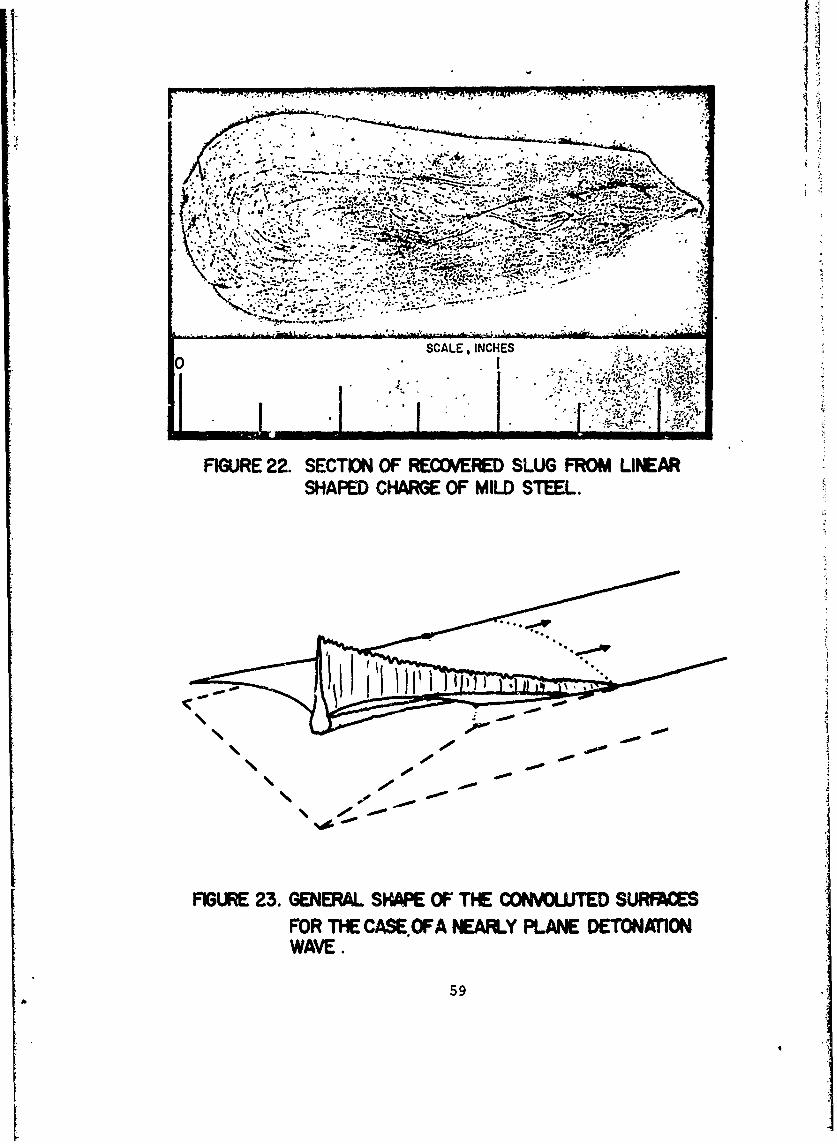
The difficulty here is that recovered portions of the
slug such as the cross-section shown in Figure 22, evidence
a coalescent rather than a dispersive inception. Indeed,
the very fact that the jet and slug have been recognized
as separate entities since the earliest experiments strongly
suggests that there exists a crossover point where the
32

velocity gradient changes sign. That point, the dividing
line between the jet and slug, is the point of equal
velocities described by Eichelberger, et al.
Applying the concept of a coalescent slug to our
propagation model without further alteration it is seen to
destroy the energy balance noted above. What is needed to
restore this balance is the adjustment of the formation
concept to allow formation of the leading edge of the slug
at the position r = 0. The following table summarizes the
two hypotheses.
GARCIA
TJ = 0 LE TE SL HIGH V. LOW VSL TESL FORMED AT=0
1 = 7MAX TEj LESL LOW V HIGH VSL SLUG DISPERSIVE
BROWN
0 LE. LE HIGH V. LOW V LE FORMED ATj SL jSL SL 1=0
11= nMAX TE TESL LOW V. HIGH VSL SLUG COALESCENT
But, applying either hypothesis to the new model;
(18) (VSL)n < (VsL)n+Arn
Thus, from Equation (14)
(19) sin < (VD) sin(VD n sin (2)n Dn+An 2 +A
33

again for (VD)n (VD) f+Ai:
(20) sin (2 )n < sin( 2.+A)
Combining inequalities 17 and 20;
(17) WO+) n >WOn+An
(20) < o n (0-0 nTi n+Ari
leads to the conclusion that the spray angle a is the
important parameter when relating dispersion/coalescence
effects of propagation to the kinematics of impact. In
order for the inequalities to hold a must decrease with
increasing n.
Returning to Figure 10 an equality relationship can be
seen between the incidence angle i and the spray angl a.p
This relationship, derived mathematically by Garcia, is
corroborated nicely by the hydraulic analogy of a water jet
impinging on a flat smooth surface. This then links the
significant parameter of dispersion, a, to the geometrically
defined convoluted surface. To control the dispersion/
coalescence of the jet/slug one must control the angle
between the convoluted surface and the plane of symmetry
measured in the plane of the streamline that is perpendicu-
lar to the symmetry plane. The prediction then is that a
"flattening out" of the two convoluted surfaces with in-
creasing E will occur. This situation, depicted in Figure
34

23, is exactly that predicted by Sewell in Reference 1. The
important dispersion variable then in terms of the input
functions to the geometrical generation of the convoluted
surface is the variation of acceleration across the vane (?
as a function of n). The design variable of detonation wave
shape can be seen to have significant influence on the
impingement angle through contortion of the convoluted
surface. A secondary design variable in the angle formation
is the shape of the liner wall as stated previously. Refer-
ence 16 concerns a test program where some of these variables
were arbitrarily altered in a conical shaped charge. The
results of these tests (classified confidential) lend cred-
ance to the selection of these variables as significant.
Detonation wave shaping is physically attainable by means
of inert buffers, multi-point initiators, or lens charges
with the latter method exhibiting the most flexibility.
Maintenance of detonation wave shape throughout the length
of the charge will probably require the imposition of a
varience of deflagration rate with radius. This can be
attained by means of a variable density of inerting
ingredient.
Additional constraints are imposed on the design process
by the dynamic yield strength of, and sonic (elastic wave)
velocity in, the liner material. These limits are thoroughly
explored and delineated by R.G.S. Sewell in Reference 17.
The resulting limits on hydrodynamic jet formation, a func-
tion of liner velocity normal to the plane of symmetry,
a35

are presented in terms of collapse angle and wall velocity.
Given a particular value of detonation velocity these
constraints translate into an upper and lower bound on the
angle of incidence criterion of the optimization model
presented here. This factor provides the only link with
liner material properties necessary to dispersion/
coalescence control.
36 j

VI. CONCLUSION
A methodology has been presented that combines existing
theory with a means of introduction of empirical data into
a design process. Implementation of this approach is
envisioned in several successive steps. A test program
along the lines of that mentioned in Section V would be
conducted utilizing the proposed liner material. These data
would then be transformed into numerical form. Ideally,
these fixed parametric functions would then be combined
with the design variables in a computer program that pro-
vided a cathode ray tube display. The designer could then
study the effect of variations in the design inputs and
search for a solution that appears to offer a relatively
constant value of i . This solution could then be refined
by a machine solution for the angle at finite increments
of . A test specimen then built to the design values
should provide some means for refinement of the process.
37

APPENDIX A
FEASIBILITY STUDY OF EXPERIMENTAL FUNCTION ANALYSIS
A. GENERAL
The work described herein was undertaken in support
of the theoretical analysis that forms the main body of
this thesis. The goals of this investigation were as
follows:
1. To attempt to verify, in general, Sewell's
description of the longitudinal variation in
liner acceleration.
2. To attempt to identify the discontinuities in the
instantaneous displacement of the liner by experi-
mental means.
3. To determine whether or not the use of Sewell's
approximation to the longitudinal wall displacement
function entailed appreciable error.
4. To probe the feasibility of using similar but more
sophisticated experimental means to accurately probe
the C- and -rj plane displacement functions under
steady state detonation conditions.
The data base for this experiment was derived from pictures
that were generated for a comparison study of LSC configur-
ations by the Naval Weapons Test Center at China Lake,
California. Their adaptation to this study was dictated by
the lack of adequate explosive test facilities at NPS, as
well as, the significant expense of such a test program. It
38
Iwas felt that the data at hand, while marginal in many
respects for this type of work, was adequate for the feasi-
bility study proposed.
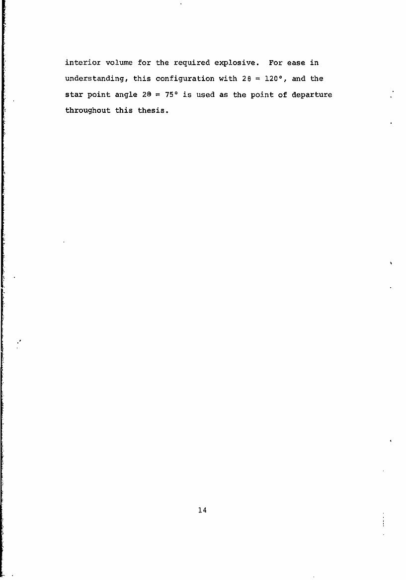
B. EXPERIMENTAL METHOD
A collage of framing camera photographs comprised of
one full test run (shot #13) is presented as Figure 24.
Examination of the first photograph (labeled zero) reveals
the test setup utilized. An eight inch square piece of
1/8 inch mild steel was formed into the trough shape shown
with a different included angle (20) for each shot. Since
the original purpose of this data was to investigate the
effects of various outside corners or "star points" (see
Figure 3) the explosive was placed inside the trough. A
piece of 2" I.D. plastic pipe was cut to conform to the
20 angle, cemented to the steel, and the combination was
butt-glued to a piece of 3/8" clear plexiglass. The result-
ing vessel was weighed, checked for volume, filled with
Composition C-3 explosive, and then reweighed for charge
density control. An electric detonator was then fitted to
the charge and the steel painted a bright red for contrast
with the background (original pictures are 35mm color). A
thin black mylar tape was used to apply a one inch grid
to the outside faces. Each charge was then mounted over a
mirror inclined 450 to it's axis and a Cordin framing
camera was oriented so as to combine side and end views in
each picture. The framing camera was set to expose one
frame per microsecond after charge initiation.
* 39

C. LIMITATIONS IMPOSED BY THE DATA
Despite the fact that the sighting plane minimizes edge
effects, the charges used in acquiring these pictures were
too small to guarantee their exclusion. Achievement of
steady state detonation and the spherical nature of the
detonation wave were not important due to the geometry of
the camera sighting plane. Strangely enough, it was the
mylar tape grid that most severely limited the experiment.
Even under the extreme forces imposed, the mylar constrained
the free surface of the steel enough to cause large periodic
"holes" in the displacement curve. This effect is readily
seen in Figures 25 and 26 which are samples of 54 such
sheets used in the data reduction.
A further difficulty was brought into the picture by
the choice of steel as the liner material. Carbon steel,
and indeed, any alloy of iron, exhibits a phase change at
a pressure of 190 Kbars. This phase change is accompanied
by a sharp discontinuity in the Hugoniot curve at that
point. This, of course, violates the constant plastic
wave speed assumption of the reverberation time approach.
D. DATA REDUCTION
After many unsuccessful attempts by other means, the
following sequence was used to "read" the instantaneous
displacement curves:
1. The pictures were projected horizontally by a remote
focusing projector a distance of 13 feet 4 inches
40

onto a flat vertical surface. A piece of 16" by
10" graph paper with a 0.1 inch grid was taped to
the surface in such a way, that it could be moved
and re-registered to each picture before tracing
the outline of the liner free surface. The results
are shown (typical valubo) in Fig. 25.
2. The graph paper was read with a magnifying glass
describing the curve in hundredths of an inch every
tenth of an inch as a table of digits.
3. The tabular values were plotted on semilog paper,
thus expanding the displacement linearly while con-
tracting the distance behind the detonation wave
logarithmically [Fig. 26].
4. An attempt was made to correlate the discontinuities
on the resulting curves with those predicted by
Sewell's analysis and depicted in Figure 15.
Each step in the above process was undertaken as a separate
series of independent value judgements to preclude the
"manufacture" of favorable values. Attempts to differentiate
the displacement curve to describe the velocity function
were unsuccessful due to the large number of missing points
caused by the mylar tape.
E. RESULTS AND CONCLUSIONS
The attempt to locate and fix the reverberation dis-
continuities was largely frustrated by the mylar tape
effects. A measure of statistical correlation was exhibited
41

however that leads to the conclusion that the effects of
the nonlinearities caused by the rapid change in properties
of the liner when subjected to the shock pattern are such
as to bring the liner displacement closer to Sewell's
approximating function. The measure of repeatability in
the curves seems to offer sufficient justification for use
of a similar method to generate the input to a charge
design program. A polynomial or exponential curve fit to
such an empirically derived curve could successfully account
for anomalies such as the phase change evidenced by steel
liners.
42

FIGUFE 1. SIMPLE CONCEPTUAL MODEL OF THE LINEAR SHAPEDCHARGE.
VD zVeIocityor Detonalon Front Deao Frn
L = Length of Charge
FIGURE 2. DETONATION PROCESS IN SIMPLE LINEAR SHAPEDCHARGE.
A 43

.5.
'IU£
r.
LL-
44
z
Liner
DETDNATIve of EFfpWT
a0
x Line45

Ize
knpoct Of. Sand S
p
-Curve Of Impact C
Sttreamine S,
Liner
FIGURE 6. LINER FLOW AND STREAMLINE COORDINATES.
46

4 W
06 0
47 4
w
w
K-
CD
WO 48

w
Ii
a 0.
.06006?
49I

V
C,,C I w
I E
w
U0I-
________ IIQ
C'I LL
50
I,

2
I; [1I ~ *iI II '1II IiII I iiIi ii I
I ~ ~I II 3ii Ii ii U,I I II *Ij ~ii ii iiii iiII ji II LU
I jiii :1 III II
] J U zC4 V
* I
I- I-
wC
1 Fl Fl ~Ij II II ji ~
ii ii EI ji ji ~
ii ~Ij Ii jiIi ~,I I III Ii II -II II -
I I WI ~
II~II:
C. V0 0 0 0 -
S U * II- I- I-
A
51

FIGURE 12.CONSTANT ANGLE IDEALIZED COLLME CASE.
KEj
MIL
+1
090 ISO
FIGURE 13. BALANCE BETWEEN MASS AND KINETIC ENERGYDMVSON FOR THE IDEALIZED COLLAPSE CASE.
52

48. 30EDE
45. toEGE
(Inch".)
13.
0 I2 3 4 5 6
FIGURE 14. DISPLACMN HISTORY ACROSS THE VANE
FGWE 15. SHOC WAVE INT ERACTION BEHIND THE DETONAM1NFRONT
53

4trVo 3 trVD 2 tr VD trVD 0
FIGURE 16. LINER DISPLACEMENT AS AFFECTED BY LONGITUDINALACCELERATION VARIATION (APPROXIMATING FUNCTION)
II
DEG\ ,900FT/SEG
18 DEG
.1
FIGURE 17 SUMMATION OF VELOCITY VECTORSM.
54
2;~
0
J wa J W II W~
0
NN
40
0
0
-P -I- N -0
(.L3SUVJ VOWdUV NHO OW~ SW'alL3WVlOi 3NOO NI NOI.LVW.3N3d

w w w w w0
LL.
0 0 00 0 00 0
o 0-~-3WAIA 310
~ U U U U U 5

IL I
Op)
57

400
58
9. 1~
-~~ -!.64*
& C. -.-7
SCALE,INCHES .4:
_______________________IFIGURE 22. SECTION OF RECOERED SLUG FROM LINEARSHAPED CHARGE OF MILD STEEL. -
FIGURE 23. GENERAL SKAPE OF THE CONVWTED SURFACEFOR THE CASE. OFA INEARLY PLANE DETQN~nCNWAVE.
59

Fll
E-4J
Alm E-4
1.7.
0~z
vow
vvl

[F
EL _ ---------- ___- - -I-
F- VK
- , - ~I*;
* -~
* I w
4,
0U
-t ~'.-$- ~14
r 4 [~* 2.
*1
63.
~ Jr.

.. .... H44-J4.. f I]
Is 1
F :~(~p~ 25 ~RACIHG OI ..WE ........ ..~AC DIP1C...'
CURVES (TYPICl]
.... ... ]. .

r r r r r r r r rm r
M1,01
1UL g~ 0i
It I 3fl
FIUR . 6 E.ANE .L~ USE IN L.ATO 0. . F .. un= l
.UFC .IC N IUTE .(T...YP...IC- --- L ---.112j, 63 4

REFERENCES
1. Sewell, R.G.S., The Collapse Process of the End-Initiated Linear.Shaped Charge, Naval Weapons Center,China Lake, California, August 1965.
2. Naval Missile Center Report TM-67-64, The End-InitiatedLinear Shaped Charge: An Analytical Model, by M.A.Garcia, 1 December 1967.
3. Ballistic Research Lab Report 405, The Initial Veloci-ties of Fragments from Bombs, Shells and Grenades,R.W. Gurney, 14 September 1943.
4.. NAWY1EPS Report 7592, Table of Initial Fragment Veloci-ties Calculated from Gurney- and Sterne Formulas forVarious C/M Ratios and Explosive Energies, J.A. Weeks,22 December-i960
5. Ballistic Research Lab Report 1296, Penetration ofShaped-Charge Jets into Metallic Targets, R. DiPersio,J. Simon, A.B. IHerendino, September 1965.
6. Ballistic Research Lab Report 1313, Theory of ResidualPenetration by Ideal Shaped Charge Jets, R. DiPersio,J. Simon, March 1966.
7. Ballistic Research Lab Report MR-1897, The Effect-ofJet Breakup Time on the Penetration Performance ofShaped, Charges, R. DiPersio, J. Simon, January 1968.
8. Ballistic Research Lab Report MR-1542, The Penetration-Standoff Relation for Idealized Shaped-Charge Jets,R. DiPersio, J. Simon, February 1964.
9. Naval Ordnance Test Station TP 3327, Walleye WarheadAnalysis; Jet Effectiveness Against Various TacticalTargets (U), E. Breitenstein,March 1964, Classifed ConEdential,
10. Naval Ordnance Test Station TP 3476, Walleye WarheadAnalysis; Effectiveness Against Light Bridges (U),Astro Technology Corp., February 1964, ClassifiedConfidential.
11. Naval Ordnance Test Station TP 3624, A Study of the.Walleye Warhead Effectiveness (U), R. Smith, D. Davis,August196A, CiassifiedT Contident-a-1
12. Naval Ordnance Test Station TP 2958, A Large LinearShaped Charge Warhead (U), _P. Cordle, M. McCubbin,September 1962- Classified Confidential.
64

13. Naval Ordnance Test Station TP 3301, Linear Sha edCharge- Study (U), E. O'ConnOr, August -1963, lassi-
: fied Condifential
14. Pugh, E. M., Eichelberger, R. J., and Rostoker, N.
"Theory of Jet Formation by Charges with Lined Conc.l
Cavities," Journal of Applied Physics, V. 23, pp.532-536, May 1952.
15. Eichelberger, R. J., and Pugh, E. M., "ExperimentalVerification of the Theory of Jet Formation byCharges with Lined Conical Cavities," Journal ofApplied Physics, V. 23, pp. 537-542, May 1952.
65
1
.1

Security ClassificationDOCUMENT CONTROL DATA.- R & D
(Sceutity classifteatlon of t. body of absftCt andt tndsxlng annotation must be entered when the overall report is Ilassiftd)I. OtraImIATING. ACTIVITY (Croaeato)2A. REPORT SECURITY-CLASSIFSICATION'
(Corprateauthr) I UnclassifiedNaval Postgraduate-SchoolK'Monterey, California 93940 bGRP
3. REPORT TITLE
A ,NEW OPTIMIZATION THEORY FOR THE END-INITIATED LINEAR SHAPED CHARGE
'4.,OESCRIPTIVC NOTES (7 rpo of mpoit and.inclustve dae&.)
'Master's Thesis; October 1969-11 AUTNOR(S) (Pirt nASA, Altddit Initial, last name)
George Elliott Brown, Jr., Lieutenant, United States Navy
S.REPONqT DATE 78s. TOTAL NO. OF PAGES -7.NO.* OF REFs
October 1969 1508. CONTRACT OR GRANT44O. S.ORIGINATOR'S REPORT NUM99RtU)
b. PROJZCT-NO.
C. 9b. OTHER REPORT NOIS) (Any other numbers flstatmy""ast,this report)
[email protected] STATEMENHT
This document has been approved for public release and sale;its distribution is unlimited.
'II. ~PL~tEN7~Y ~O7~12. SPONSORING MILITARY ACTIVITY
Naval Postgraduate School
t * AaTRACTMonterey, California 93940
_An exposition of the two existing analytical approachesto the end initiated linear shaped charge is made. Aftera 'theory is put forth relating optimizaiaon to increasedenergy transfer at increased standoff distances, this effectis linked to the dispersive nature of the jet mass. An-analytical design approach is then formulated that combineselements of both existing models. The object of this ap-proach is to integrate experimental data into a mathematic-ally definitive analysis. A theoretical link is.thendeveloped between the dispersive nature of the jet and thedesign input paramets~rs, thus completing the optimization
model0(,
DFORM (PAGE 1)DDI Nov 05 47
S/N 4O101-807-6811 67 Se0curity Classification*A- 3140

Secuify -lsilto
14KYv~t'2LIN. A LINK 0 LINK C
X01. WT ROLE. WY R'OLC -*T
LINEAR SHAPED CHARGE
WARHEAD,
EXPLOSIVE CUTTING
fff FORM I A -71 SfAIV
d~INO6B39%D ''~"'UNCLASS IFIEDS/N 0101-807-6821 68 Security Classification A-it109