NAVAL POSTGRADUATE SCHOOL · Naval Postgraduate School ... include loading packet data into a...
79
NAVAL POSTGRADUATE SCHOOL MONTEREY, CALIFORNIA THESIS MULTI-RESOLUTION PLAYBACK OF NETWORK TRACE FILES by Scott Fortner June 2015 Thesis Co-Advisors: Geoffrey Xie Justin Rohrer Approved for public release; distribution is unlimited
Transcript of NAVAL POSTGRADUATE SCHOOL · Naval Postgraduate School ... include loading packet data into a...
NAVALPOSTGRADUATE
SCHOOL
MONTEREY, CALIFORNIA
THESIS
MULTI-RESOLUTION PLAYBACK OF NETWORKTRACE FILES
by
Scott Fortner
June 2015
Thesis Co-Advisors: Geoffrey XieJustin Rohrer
Approved for public release; distribution is unlimited

THIS PAGE INTENTIONALLY LEFT BLANK
REPORT DOCUMENTATION PAGE Form Approved OMB No. 0704–0188
Public reporting burden for this collection of information is estimated to average 1 hour per response, including the time for reviewing instruction,searching existing data sources, gathering and maintaining the data needed, and completing and reviewing the collection of information. Send commentsregarding this burden estimate or any other aspect of this collection of information, including suggestions for reducing this burden to Washingtonheadquarters Services, Directorate for Information Operations and Reports, 1215 Jefferson Davis Highway, Suite 1204, Arlington, VA 22202–4302, andto the Office of Management and Budget, Paperwork Reduction Project (0704-0188) Washington DC 20503.
1. AGENCY USE ONLY (Leave Blank) 2. REPORT DATE
06-19-20153. REPORT TYPE AND DATES COVERED
Master’s Thesis 07-07-2013 to 06-19-20154. TITLE AND SUBTITLE
MULTI-RESOLUTION PLAYBACK OF NETWORK TRACE FILES5. FUNDING NUMBERS
6. AUTHOR(S)
Scott Fortner
7. PERFORMING ORGANIZATION NAME(S) AND ADDRESS(ES)
Naval Postgraduate SchoolMonterey, CA 93943
8. PERFORMING ORGANIZATION REPORTNUMBER
9. SPONSORING / MONITORING AGENCY NAME(S) AND ADDRESS(ES)
N/A
10. SPONSORING / MONITORINGAGENCY REPORT NUMBER
11. SUPPLEMENTARY NOTES
The views expressed in this document are those of the author and do not reflect the official policy or position of the Department ofDefense or the U.S. Government. IRB Protocol Number: N/A.
12a. DISTRIBUTION / AVAILABILITY STATEMENT
Approved for public release; distribution is unlimited12b. DISTRIBUTION CODE
13. ABSTRACT (maximum 200 words)
Marine Corps Tactical Systems Support Activity (MCTSSA) has put forth a requirement for a non-proprietary network traffic replaysystem that is user friendly and can provide both replay of a network trace file as well as replay based on a statistical model of anetwork trace file. This thesis attempts to create such a system and to fulfil the requirements set forth by MCTSSA. The systemperforms as much preprocessing of data as possible, to include loading packet data into a database and creating binary copies ofreplay packets, which facilitates performing replays multiple times without repetitive processing work. The final system proved toaccurately reproduce a capture file with a trace-based replay, while maintaining TCP semantics and the ability to match high volumesof traffic. The major limitation is the need to potentially sacrifice timing accuracy in order to maintain TCP semantic integrity. Toaccommodate different user implementations, the system supports an option to place the priority on either sequencing or timing, whichwill guarantee one at the possible expense of the other. Lastly, the statistical model generated from characteristics of the original traceproved to accurately model the original capture and provide for a user-defined replay length. In the end, the MCTSSA requirementswere met and further expansion and enhancements were identified to improve performance and usefulness of the system.
14. SUBJECT TERMS
network replay, pcap, TCP, protocol semantics, network trace, network testing, network emulation15. NUMBER OF
PAGES 7916. PRICE CODE
17. SECURITYCLASSIFICATION OFREPORT
Unclassified
18. SECURITYCLASSIFICATION OF THISPAGE
Unclassified
19. SECURITYCLASSIFICATION OFABSTRACT
Unclassified
20. LIMITATION OFABSTRACT
UUNSN 7540-01-280-5500 Standard Form 298 (Rev. 2–89)
Prescribed by ANSI Std. 239–18
i

THIS PAGE INTENTIONALLY LEFT BLANK
ii
Approved for public release; distribution is unlimited
MULTI-RESOLUTION PLAYBACK OF NETWORK TRACE FILES
Scott FortnerMajor, United States Marine Corps
M.A., Oregon State University, 2003
Submitted in partial fulfillment of therequirements for the degree of
MASTER OF SCIENCE IN COMPUTER SCIENCE
from the
NAVAL POSTGRADUATE SCHOOLJune 2015
Author: Scott Fortner
Approved by: Geoffrey XieThesis Co-Advisor
Justin RohrerThesis Co-Advisor
Peter DenningChair, Department of Computer Science
iii

THIS PAGE INTENTIONALLY LEFT BLANK
iv

ABSTRACT
Marine Corps Tactical Systems Support Activity (MCTSSA) has put forth a requirementfor a non-proprietary network traffic replay system that is user friendly and can provide bothreplay of a network trace file as well as replay based on a statistical model of a networktrace file. This thesis attempts to create such a system and to fulfil the requirements setforth by MCTSSA. The system performs as much preprocessing of data as possible, toinclude loading packet data into a database and creating binary copies of replay packets,which facilitates performing replays multiple times without repetitive processing work. Thefinal system proved to accurately reproduce a capture file with a trace-based replay, whilemaintaining TCP semantics and the ability to match high volumes of traffic. The majorlimitation is the need to potentially sacrifice timing accuracy in order to maintain TCPsemantic integrity. To accommodate different user implementations, the system supports anoption to place the priority on either sequencing or timing, which will guarantee one at thepossible expense of the other. Lastly, the statistical model generated from characteristicsof the original trace proved to accurately model the original capture and provide for auser-defined replay length. In the end, the MCTSSA requirements were met and furtherexpansion and enhancements were identified to improve performance and usefulness of thesystem.
v

THIS PAGE INTENTIONALLY LEFT BLANK
vi
Table of Contents
1 Introduction 11.1 Requirement . . . . . . . . . . . . . . . . . . . . . . . . . . 1
1.2 Purpose . . . . . . . . . . . . . . . . . . . . . . . . . . . . 2
1.3 Scope . . . . . . . . . . . . . . . . . . . . . . . . . . . . . 2
1.4 Thesis Structure . . . . . . . . . . . . . . . . . . . . . . . . . 2
2 Background 52.1 MCTSSA . . . . . . . . . . . . . . . . . . . . . . . . . . . 5
2.2 Required Characteristics . . . . . . . . . . . . . . . . . . . . . 6
2.3 Previous Work . . . . . . . . . . . . . . . . . . . . . . . . . 7
3 Methodology 113.1 Abstract View of Source Network. . . . . . . . . . . . . . . . . . 11
3.2 The Two Part Process . . . . . . . . . . . . . . . . . . . . . . 13
3.3 The Process – Segment 1 . . . . . . . . . . . . . . . . . . . . . 14
3.4 The Process – Segment 2 . . . . . . . . . . . . . . . . . . . . . 21
3.5 The Deliverable . . . . . . . . . . . . . . . . . . . . . . . . . 27
4 Implementation 294.1 Language Choice . . . . . . . . . . . . . . . . . . . . . . . . 29
4.2 Library Usage . . . . . . . . . . . . . . . . . . . . . . . . . 30
4.3 Database Software . . . . . . . . . . . . . . . . . . . . . . . . 30
4.4 Flow Generator . . . . . . . . . . . . . . . . . . . . . . . . . 30
4.5 Limitations. . . . . . . . . . . . . . . . . . . . . . . . . . . 31
5 Testing and Evaluation 355.1 The Test Environment . . . . . . . . . . . . . . . . . . . . . . 35
5.2 Packet Accuracy . . . . . . . . . . . . . . . . . . . . . . . . 36
5.3 Sequencing Accuracy . . . . . . . . . . . . . . . . . . . . . . 37
vii
5.4 Timing Accuracy . . . . . . . . . . . . . . . . . . . . . . . . 37
5.5 Statistical Testing . . . . . . . . . . . . . . . . . . . . . . . . 37
6 Validation 396.1 Sequencing. . . . . . . . . . . . . . . . . . . . . . . . . . . 39
6.2 Timing . . . . . . . . . . . . . . . . . . . . . . . . . . . . 48
6.3 Packet Accuracy . . . . . . . . . . . . . . . . . . . . . . . . 50
6.4 Statistical Modelling . . . . . . . . . . . . . . . . . . . . . . . 51
7 Conclusion and Future Work 557.1 Future Work . . . . . . . . . . . . . . . . . . . . . . . . . . 55
7.2 Conclusion . . . . . . . . . . . . . . . . . . . . . . . . . . . 58
Appendix: Source Code 59
List of References 61
Initial Distribution List 63
viii

List of Figures
Figure 3.1 Two Node Network Example . . . . . . . . . . . . . . . . . . . 12
Figure 3.2 Replay System Functional Diagram . . . . . . . . . . . . . . . . 12
Figure 3.3 Top-Level Design . . . . . . . . . . . . . . . . . . . . . . . . . 13
Figure 3.4 Database Schema . . . . . . . . . . . . . . . . . . . . . . . . . 17
Figure 3.5 Configuration File Format . . . . . . . . . . . . . . . . . . . . . 18
Figure 3.6 Statistical Hierarchical Model . . . . . . . . . . . . . . . . . . . 19
Figure 3.7 Playback Without Latency Factored In . . . . . . . . . . . . . . 24
Figure 6.1 Case 1: ti≥ 2d,Pi.dir = SEND,Qi.dir = RECV . . . . . . . . . 43
Figure 6.2 Case 2: ti < 2d,Pi.dir = SEND,Qi.dir = RECV . . . . . . . . . 44
Figure 6.3 Case 3: Pi.dir = RECV,Qi.dir = SEND . . . . . . . . . . . . . 45
Figure 6.4 Case 4: Pi.dir = SEND∧Qi.dir = SEND∧Ti(Q)> Ti(P) . . . 46
Figure 6.5 Case 5: Pe.dir = RECV ∧Qe.dir = RECV ∧Ti(Q)> Ti(P) . . . 46
Figure 6.6 Single Flow Throughput . . . . . . . . . . . . . . . . . . . . . . 49
Figure 6.7 Multi-Flow Throughput . . . . . . . . . . . . . . . . . . . . . . 51
Figure 6.8 Large Test Sample 1 . . . . . . . . . . . . . . . . . . . . . . . . 52
Figure 6.9 Large Test Sample 2 . . . . . . . . . . . . . . . . . . . . . . . . 53
ix

THIS PAGE INTENTIONALLY LEFT BLANK
x
List of Tables
Table 2.1 Previous Work Comparison . . . . . . . . . . . . . . . . . . . . . 10
Table 3.1 Sample Common Ports Used for Flow Groups . . . . . . . . . . . 20
Table 6.1 Notation . . . . . . . . . . . . . . . . . . . . . . . . . . . . . . . 40
Table 6.2 Sequencing Comparison Between Latency Values (Measured La-tency of 140 Msec on Multi-Flow Capture) . . . . . . . . . . . . 50
Table 6.3 Accuracy Evaluation Values For Automated Test . . . . . . . . . 52
Table 6.4 Statistical Ratios of Experiment 1 . . . . . . . . . . . . . . . . . 54
Table 6.5 Statistical Ratios of Experiment 2 . . . . . . . . . . . . . . . . . 54
xi

THIS PAGE INTENTIONALLY LEFT BLANK
xii
List of Acronyms and Abbreviations
C4 Command, Control, Communications, and Computers
gro generic receive offload
gso generic segmentation offload
GUI graphical user interface
IANA Internet Assigned Numbers Authority
IDE Integrated Development Environment
IP Internet Protocol
MCTSSA Marine Corps Tactical Systems Support Activity
NIC network interface card
NPS Naval Postgraduate School
OSI Open Systems Interconnection
pcap packet capture
TCP Transmission Control Protocol
tso TCP segmentation offload
UDP User Datagram Protocol
WAN wide area network
xiii

THIS PAGE INTENTIONALLY LEFT BLANK
xiv
CHAPTER 1:
Introduction
Network owners and administrators are always interested in enhancing the usefulness andmaximizing the performance of their networks and they spend a significant amount of timeand money testing products and methodologies aimed at accomplishing these goals. Inorder to verify their effectiveness, these products must be tested and evaluated under op-erational conditions. Accurate and relevant evaluation requires either implementing andtesting these ideas onto the operational network, which is typically impractical or impos-sible, or creating a test network that accurately emulates the target network. The ability toappropriately emulate a network relies on accurate representation of network traffic con-ditions, and if accomplished, removes the need to utilize the operational network itself fortesting. The challenge, therefore, lies in creating this emulation network traffic in an accu-rate and realistic way. Proprietary hardware solutions do exist, but they tend to be expensiveand non-specific in terms of implementation choices [1]. For many organizations, the costis either too high, the product does not conform to testing requirements, or both.
In order to produce as accurate a test environment as practical, the emulation system mustconsider the actual network traffic on a given network as well as the hardware constraints.In order to accomplish this, network traffic must be recorded or monitored and evaluated todetermine common characteristics such as the frequency of packets, the ratio of commonprotocols, and the packet payload sizes, among others. Additionally, the system must beable to recreate events of interest such as congestion.
1.1 RequirementThere is currently a requirement raised by Marine Corps Tactical Systems Support Activity(MCTSSA) to develop a system to create such a test environment. The capability to ac-curately emulate and replay network loads must be based on samples of network traffic asrecorded in pcap files, which are a common file format for storing network traffic data inprograms such as Wireshark [2]. The desired use for this capability by MCTSSA is primar-ily to test network optimization products such as Wide Area Network (WAN) Optimizersand compression utilities, but also to provide network replay and emulation for unit train-
1
ing purposes. MCTSSA does not posses the resources necessary to purchase a proprietarytest system such as PacketExpert by GL Communications, nor do they desire the generictesting requirements fulfilled by some such systems.
1.2 PurposeThe purpose of this thesis is to develop a system for network emulation and replay thatmeets the requirements placed by MCTSSA. The system will utilize recorded networktraffic in the form of a pcap file to provide the data for an trace-based replay capabilityas well statistical modelling that will create a network load emulation capability. The pcapfiles provided by MCTSSA will be used by the system to create a test environment designedto meet product evaluation and training needs of the Marine Corps.
1.3 ScopeThe system designed during this thesis will provide both a packet-by-packet replay of apcap file and a playback based on statistical analysis of a pcap file. The system will beuser friendly, not rely on any proprietary products, and maintain original packet and flowintegrity as well as timing during trace-based replay conditions. Additionally, the charac-teristics of the original capture file will be modelled in a statistical replay option.
Timing, in the context of this thesis, refers to packet throughput or the number of packetsobserved over a specific time interval. the claim that a replay system maintains timingsimply means that the throughput of this replay system can recreate the original throughputpattern, especially under heavy loads.
This thesis will show that such a system can be developed and that packet sequencing,accuracy, and timing can be maintained entirely or to a reasonable degree, both in termsof timing and maintaining protocol semantics. Furthermore, the designed system will beprovided to MCTSSA fully configured and ready for use, per the specified requirements.
1.4 Thesis StructureChapter two of this thesis will discuss the MCTSSA requirement for a network trafficreplay system as well as some of the previous work completed in the area of network trafficreplay. Chapter three will cover, in detail, the methodology for designing the replay system,
2

followed by the implementation-specific details in Chapter four. Following these designand implementation specifics, the test environment and methodology will be explained(chapter five) and the validation from this testing will be presented in chapter six, alongwith more formal validation for timing requirements and limitations of the system. Finally,chapter seven will discuss future work on the replay system as well as a summary of therelevant findings.
3

THIS PAGE INTENTIONALLY LEFT BLANK
4
CHAPTER 2:
Background
2.1 MCTSSAMCTSSA “provides test and evaluation, engineering, and deployed technical support forUSMC and joint service command, control, computer, and communications (C4) systemsthroughout all acquisition life-cycle phases” [3]. Their responsibilities include testing newdevices, services, and procedures that the Marine Corps has or is interested in acquiring.This includes network optimization products such as Wide Area Network (WAN) optimiz-ers and products for adjusting video streaming quality to accommodate real-time networkbandwidth loads. Additionally, MCTSSA provides training support for Marine Corps unitswhere they repair and evaluate the effectiveness and efficiency of C4 systems.
Currently, when testing network optimization tools, MCTSSA uses a generic network traf-fic generation tool to emulate a C4 environment. Although this method does provide feed-back on the usefulness of the optimization tool, MCTSSA requires the ability to evaluatethese tools in true Marine Corps network environments in order to obtain non-generic re-sults. Furthermore, the Marine Corps maintains C4 equipment at all levels of commandwhere the size and scope of the systems varies significantly between these levels. Due tothe significant differences between these systems, generic network testing is not guaran-teed to produce accurate results and certainly is not guaranteed to differentiate those resultsbetween command levels.
As an example, a WAN optimizer might prove to be very useful at a higher level of com-mand, which utilizes a much larger network, but not provide enough of an improvement ata lower level to warrant the investment. With the ability to test this WAN optimizer at eachlevel, the usefulness of the device at each level can be accurately determined, leading tobetter investment and spending decisions.
MCTSSA already maintains a variety of network capture files from these various MarineCorps commands utilizing various C4 equipment as well as systems to emulate physicalnetwork characteristics. What they currently lack is a software tool to replay these capture
5
files in their emulated network test environment. Unfortunately, they lack the time andresources to create or fund the creation of this tool so they continue to work with genericnetwork traffic generators and estimations of performance data.
2.2 Required CharacteristicsIn order to properly meet the requirements placed by MCTSSA, the proposed system re-quires certain characteristics with regards to functionality and behavior. These include theability to replay a captured traffic file packet-by-packet as well as the ability to generateand play a statistical model of the captured traffic, all with accurate timing and sequencingof the packets. This section will discuss these important aspects and the next section willdiscuss how these characteristics are/are not met by previous work.
2.2.1 Trace-based ReplayTrace-based replay, in this context, means that the traffic sent over the network duringreplay is identical to the traffic contained in the capture file, with few exceptions. Thepackets themselves must be identical from the network layer up. The physical and linklayer information can be modified to meet the requirements of the test environment. Forthe designed purposes of the system, changing this information will have no effect on theusefulness of the replay.
The ability to reproduce the exact contents of the original packets is vital to the abilityto properly test network optimization and analysis tools, such as WAN optimizers. Thesetools examine various portions of the packet data, to include the options and payload, whileperforming their tasks. Without perfectly recreating these packets, the performance andusefulness of these tools is unpredictable.
2.2.2 Statistical ReplayStatistical replay in this context means that the original captured traffic is analyzed forpatterns such as overall packet frequency, types and recurrence of transport layer protocols,timing between packets, timing between flows, and number and length of flows, amongothers. Once this statistical information is gathered, the system generates a new trafficpattern that mimics these characteristics of the original capture, but can be repeated for anydesired amount of time.
6

2.2.3 Accurate SequencingAccurate sequencing refers to the ordering of packets during playback. By maintainingthe order of packets, not only is the ordering within each single traffic flow maintained,but the ordering between different traffic flows is also maintained. The ability to retainthe relative order of packets is vital for achieving trace-based replay (accurately recreatingthe recorded network traffic load). That being said, the ordering of packets with respectto each other may still potentially change from the original, but only in such a way as toretain the integrity of TCP flow semantics, in order to provide accurate stateful playback.Additionally, for realistic network emulation in a statistical replay environment, the orderof packets must be maintained in order for the traffic patterns to not be nonsensical. Anexample of nonsensical replay would be sending out of order TCP packets where the firstdata packet is sent before the 3-way handshake has begun. For the same reasons offeredfor inaccurate packets, nonsensical packet ordering would lead to unpredictable behaviorby network optimization and analysis tools.
2.2.4 Accurate TimingIn order to meet the trace-based replay requirements as well as maintain the timing ofthe calculated statistical model, the system must be able to meet the timing requirementsspecified for the replay, to a reasonable degree. This simply means that during trafficreplay, if the timestamps of packet arrivals and departures were to be observed, they wouldmatch the timestamps of packet arrivals and departures in the original trace. This allowsfor accurate recreation of the packet throughput of the original trace. Without the abilityto accurately mimic these timings, and thus the throughput, neither replay models could beproperly achieved.
2.3 Previous Work2.3.1 Previous ThesisThe MCTSSA requirement for a traffic replay system has already spawned a thesis responseat Naval Postgraduate School. Although the replay system was not designed in its entirety,A Tool For Stateful Replay by Thomas Le Vier [4] laid the groundwork for this thesis to pro-vide a complete product. The previous work developed several of the key implementationconcepts that include the use of a database to store the packet data, the use of configuration
7
files for directing the replay action, the choice to leverage packet manipulation languagelibraries, and the decision to divide the system into functional parts. All of these designdecisions will be discussed in detail in Chapter 3. Le Vier managed to accurately organizethe captured network traffic into a database, pull a single TCP flow out of the database, andaccurately replay this TCP flow between two nodes. Although this was a good start in thedevelopment of this system, it was far from reaching the replay requirements set forth byMCTSSA.
2.3.2 TCPivoTCPivo is a traffic replay tool that was developed in 2003 and discussed in the articleTCPivo: A High-Performance Packet Replay Engine. Although this product shares severaldesign features to this system, there are key components from MCTSSAs requirements thatare missing.
TCPivo is designed to produce trace-based replay from a capture file. Instead of pre-processing the file data, as this system does, TCPivo reads the packets from the file inreal-time, relying on pre-fetching techniques to maintain timing accuracy (requiring OSkernel modification). The capture file is read and parsed for every run of the replay, withno ability to customize the playback. For example, retransmissions in the capture file arenot removed by the replay process. Additionally, there is no support for statistical emu-lation based on the capture file. A TCPivo user would have to look to other products forthis.
Similar to this system, TCPivo does use commodity hardware and general use softwaresuch as Linux, but requires kernel patches and does not provide a stand-alone virtual devicewith these patches pre-configured. Although all software and code is made available tousers, configuration and kernel patches must also be accomplished by the user. This doesnot meet the MCTSSA requirement for a plug-and-play system.
The single user option provided by TCPivo is to substitute actual payload data with nullpadding. The purpose for this is to increase the speed at which the packets can be replayed,but, as the authors note, null padded payload is not practical for many networking tests.
Finally, there is no mention in the TCPivo article about what protocols are or are not re-
8
played, such as UDP packets. Accurate replay of an organization’s network utilizationwould require UDP packets to also be replayed, while at the same time eliminating someof the low-level messages such as ARP requests and responses.
2.3.3 On Interactive Internet Traffic Replay (TCPopera)In 2005, Seung-Sun Hong and S. Felix Wu wrote a paper discussing another network trafficreplay tool called TCPopera [5]. Like this system and TCPivo, TCPopera uses capturednetwork traffic as the basis for traffic replay. However, TCPopera does not provide trace-based replay of this captured data. Instead, it develops analytics from the captured data andcreates a statistical model based on this data, exactly what this system provides as one ofthe replay options.
With a primary focus on network security and intrusion prevention systems (IPS) testing,TCPOpera is more concerned with modifying the original trace to meet certain testingdesires while re-creating all aspects of TCP control. The main goal of this system is toperform trace-based replay of recorded traffic for injection into test and training networks,with a secondary option for statistical based playback. TCPopera is designed with thenarrow primary goal of providing a test-bed for network security specific devices.
TCPopera’s focus on flow structure allows for very accurate intra-flow sequencing. Thesystem uses a single thread for managing each flow. What this does not provide for is inter-flow sequencing, which is also important when providing trace-based replay. AlthoughTCPopera uses a very similar two-phase approach of pre-processing followed by replay,the replay itself is not based entirely on ordering and timing of the original trace. Instead,TCPopera uses a single control node and control messages passed out-of-band between thenodes to facilitate replay parameters of a statistically similar traffic pattern.
Although TCPopera includes UDP and ICMP traffic, its primary focus is on TCP trafficand the results and validation of the tool focus almost entirely on TCP measurements.The authors also claim that scalability is one of the design goals, but by utilizing out-of-band control channels, TCPopera becomes limited by the complexity of control channelconnections as the scale increases.
Other shortfalls were identified by the authors themselves. TCPopera implements TCP
9
flow reconstruction in such a way that some TCP connections remain open for much longerperiods than desired or required. Since these connections occupy a larger portion of a finitereplay time, less time remains for follow-on connections, leading to those connections orflows being cut short. For IDS or other network testing devices, missing packets in TCPflows may mean that the tool will be inaccurate or unusable.
It was unclear how the authors of TCPopera validated correct TCP semantics. Not onlywere the semantics not defined or described, they were claimed as valid without explanationas to how this validity was determined. This leads to uncertainty about their claim. Anotherpoorly explained area is the concept of a flow. A TCP flow was never formally defined.The authors briefly describe a flow as both packets sequences between two host as well ascontaining multiple TCP connections. Given that multiple connections will not necessarilybe between the same two hosts, the description leaves the reader with an ambiguous, atbest, description of a TCP flow.
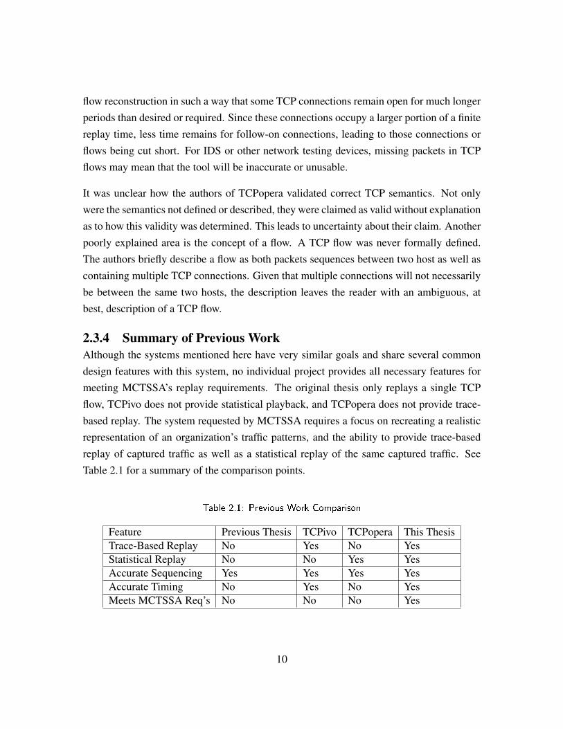
2.3.4 Summary of Previous WorkAlthough the systems mentioned here have very similar goals and share several commondesign features with this system, no individual project provides all necessary features formeeting MCTSSA’s replay requirements. The original thesis only replays a single TCPflow, TCPivo does not provide statistical playback, and TCPopera does not provide trace-based replay. The system requested by MCTSSA requires a focus on recreating a realisticrepresentation of an organization’s traffic patterns, and the ability to provide trace-basedreplay of captured traffic as well as a statistical replay of the same captured traffic. SeeTable 2.1 for a summary of the comparison points.
Table 2.1: Previous Work Comparison
Feature Previous Thesis TCPivo TCPopera This ThesisTrace-Based Replay No Yes No YesStatistical Replay No No Yes YesAccurate Sequencing Yes Yes Yes YesAccurate Timing No Yes No YesMeets MCTSSA Req’s No No No Yes
10
CHAPTER 3:
Methodology
The design decisions made in this thesis account for the majority of the research and effort.As is common within the field of Computer Science, there are many methods for solvingany particular problem, let alone a series of problems. The design of this system is noexception. This chapter will discuss the rational behind the major as well as some of theminor design choices in the project. The areas of discussion will focus on design choicesthat are unusual, critical to the required operation, or presented challenges to the project.
Due to the fact that this project is done in an academic environment and designed for use byMCTSSA, all of the source code will be open source and provided to any interested partiesunder the General Public use Licence. Additionally, consideration will be given to postingthe source code online for public access.
3.1 Abstract View of Source NetworkThe network used for the original capture of traffic can be abstracted to a very simple designof two nodes sharing a single link. Behind these two nodes could be any number of hosts,all of which send traffic to each other through this single link. In a USMC-specific context,the nodes connect multiple Marine Corps network enclaves together as well as potentiallyconnecting to external networks such as the Internet. See Figure 3.1 for an illustration ofthis.
As seen in the illustration, there is a single point of capture located at one of the nodes. Thisnode will be referred to as the internal node. The node farther away from the capture pointwill be referred to as the external node. For the purposes of correctness during the trace-based replay, it is assumed that the capture takes place immediately at the internal node andnot at some intermediate point between the internal and external nodes. The system wouldneed to know the latency from each node to the capture point, if that were the case. Thecurrent design uses latency calculations on the assumption that the traffic was recorded atone of the nodes and would be improperly implemented otherwise.
11
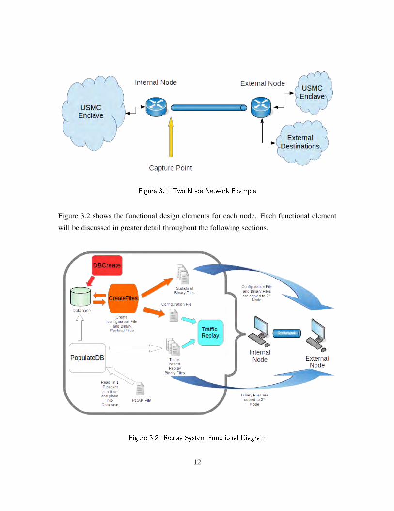
Figure 3.1: Two Node Network Example
Figure 3.2 shows the functional design elements for each node. Each functional elementwill be discussed in greater detail throughout the following sections.
Figure 3.2: Replay System Functional Diagram
12

In contrast to the functional design details, the top-level design of the replay system, asshown in Figure 3.3, consists of two nodes connected via the emulated network. Thereplayed network packets are sent between the two nodes but do not get forwarded in on toany external network or enclaves. During replay testing the traffic is recaptured a the nodecorresponding to the original internal node and this recapture can then be compared to theoriginal capture.
Figure 3.3: Top-Level Design
3.2 The Two Part ProcessSimilar to the first thesis, A Tool For Stateful Replay [4], the overall system design isdivided into two processes or segments. The decision was made to complete as much of theprocessing work up front as feasible. This provides two main positive results; to minimizethe workload during the time-critical traffic replay and to allow for multiple replay sessionsto be conducted without unnecessary repetition of the initialization work. To account forscalability, it was necessary to minimize the workload during the actual replay, due to thepotentially very high playback speed and the desire for as precise timing as possible. Thisinitialization work refers specifically to the gathering and processing of all the relevantinformation from the pcap file. If the user desires to conduct replay of the same capturefile multiple times in a row, reprocessing the recorded data would simply be redundant.
13
Once again, for scalability reasons, removing redundancy significantly increases the overallperformance.
3.3 The Process – Segment 1All reasonable pre-processing is conducted during the first segment of the system design.This includes reading every line of the pcap file, populating and organizing the databasewith all of the packet information, gathering and calculating the statistical data, and creatingthe reference files that will be used to run the traffic replay. Each of these subroutines isaccomplished via separate programs, one per task. The order that these tasks are completedis very important to avoid errors and erroneous data. If a pcap file was entered into thedatabase without erasing all previous data then the statistical data and playback wouldincorporate both sets of data. The unpredictability and inaccuracy of such data was notinvestigated in this project. Proper sequencing monitoring is incorporated into the userinterface in order to help prevent this undesirable behavior.
3.3.1 Segment 1 StructureAs mentioned previously, Segment 1 was divided up into three separate programs. The firstprogram, DBCreate, is designed to ensure the correct structure of the database. DBCreate
creates or overwrites all elements of the database schema and erases data already populatedinto the schema. For details about the schema see Section 3.3.2.
The second program, populateDB, reads a specified pcap file, line by line, and places allrelevant packet data into the database schema and marks all retransmission packets. Oncecomplete with populating the database, populateDB inspects the populated entries, groupspackets into flows, and generates flow data for easy reference later. Finally, the programcreates reference files for use in trace-based replay during Segment 2 (Section 3.4).
The third and final program in Segment 1 is CreateFiles. CreateFiles reads the flow andpacket data from the database, performs the statistical analysis and creates the referencefiles for statistical replay. For specifics about these reference files see Section 3.3.3.
3.3.2 Database StructureThe program DBCreate simply creates the required database or, if it already exists, ensuresthe integrity of the schema and deletes any data that has already been populated to the
14

database using simple “drop table” commands. The reasoning behind not combining thedatabase management with the database population is to provide the user with the flexibilityto erase the database without also re-populating it with new data. With scalability in mind,the pcap files have the potential to be very large, therefore it is beneficial to include an easymethod of removing the data from the database without having to replace it with new data.Erasing the database does not remove any of the reference files that are created by the otherprograms.
Following the creation of an empty database schema, the user will populate it using thepopulateDB program. Utilizing the libcrafter library, this program reads the pcap file onepacket at a time and parses portions of it before inserting specific packet fields into thedatabase, one field per column. To see which packet fields are stored in the database seeFigure 3.4.
Along with insertion, populateDB organizes the packet data by Open Systems Interconnec-tion model (OSI) layer, links each packet with those in the same flow to create flow groups,and assigns a unique flow number to each flow group. Along with the packet fields, thegrouping of the data in the database is used for determining statistical analysis of the pcaptraffic.
Prior to organizing the flow groups, populateDB scans the packets in order to identifyretransmissions. Retransmissions are identified in TCP packets through matching socketpairs and sequence numbers. The replay system is designed to mimic actual network traffic.Retransmissions, although part of the original capture, are typically a result of networkerrors or network limitations. In a scenario where the user does not wish to mimic a specificnetwork environment, the retransmissions are removed (via user option). In a differentscenario, such as replaying malicious traffic, retransmissions would be desired and the usercan choose to retain them. Furthermore, if the user desires replay under specific bandwidthor network constraints, then those limitations are required to be implemented external tothis system.
The packets that are used to form flow groups are identified by matching IP addresses,port numbers, and protocol type (the 5-tuple) for both the sending and receiving nodes(the socket pair). Most IP flows involves a client-server relationship where the client port
15
is a fairly unique, high value [6]. Due to this relative uniqueness of this ephemeral portselection, the likelihood of two flows between the same two IP addresses having the samesocket pair is not very likely. Although it is still possible that a particular socket pair mayexist for separate flows, this would most likely be a small number and not adversely affectthe system performance.
In order to simplify the database schema, each packet of the same OSI layer 3 protocol isstored in a single table. Due to only two prominent layer 3 protocols, IPv4 or IPv6, thereare only two tables storing actual packet data. The reason for this division is due to thefact that IPv6 support is initially not included in this project, but instead is designed forfuture work. Removing the IPv6 packets from the IPv4 table reduces the workload whensearching the table. The complete structure of the database schema, to include packet tablesand flow tables, is shown in Figure 3.4.
Lastly, populateDB creates the reference files used in Segment 2 3.4 for trace-based replay.In order to maintain packet integrity and reduce processing time, each packet is writtento a reference file and saved in a specified folder, with a unique name that matches thepacket number listed in the database. Section 3.3.3 explains the specifics of the referencefile creation.
3.3.3 The Use of Reference FilesFollowing the design of the previous thesis [4] once again, this system is designed to makeuse of reference files. More specifically, text files and binary files are used as the meansof communication between Segment 1 and Segment 2. These files supply all of the packetdata that will be used during replay.
The Binary FilesAfter populating the database, populateDB creates binary files that contain the raw packetdata for each packet in the capture file. Each packet in the database includes a uniquepacket number and the corresponding binary reference file contains this unique number inits naming scheme. The trace-based replay files are stored in a folder named “replayfiles”and the naming scheme is “bin01.bin” for packet number “1”.
Initially, the packet data was stored in the database, but not only did this make the database
16
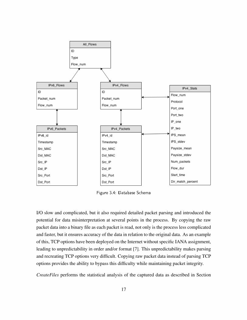
Figure 3.4: Database Schema
I/O slow and complicated, but it also required detailed packet parsing and introduced thepotential for data misinterpretation at several points in the process. By copying the rawpacket data into a binary file as each packet is read, not only is the process less complicatedand faster, but it ensures accuracy of the data in relation to the original data. As an exampleof this, TCP options have been deployed on the Internet without specific IANA assignment,leading to unpredictability in order and/or format [7]. This unpredictability makes parsingand recreating TCP options very difficult. Copying raw packet data instead of parsing TCPoptions provides the ability to bypass this difficulty while maintaining packet integrity.
CreateFiles performs the statistical analysis of the captured data as described in Section
17
3.3.4 then creates packets to be replayed during the statistical playback. Once each packetis created, the raw data is extracted and copied into a reference file in the same manner asthe trace-based replay packets. The naming scheme for the statistical replay is the same asthe trace-based replay, but the statistical replay files are placed into the folder “statfiles”.
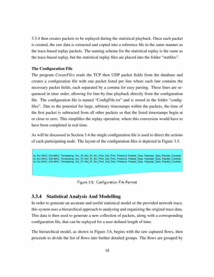
The Configuration FileThe program CreateFiles reads the TCP then UDP packet fields from the database andcreates a configuration file with one packet listed per line where each line contains thenecessary packet fields, each separated by a comma for easy parsing. These lines are se-quenced in time order, allowing for line-by-line playback directly from the configurationfile. The configuration file is named “ConfigFile.txt” and is stored in the folder “config-files”. Due to the potential for large, arbitrary timestamps within the packets, the time ofthe first packet is subtracted from all other packets so that the listed timestamps begin ator close to zero. This simplifies the replay operation, where this conversion would have tohave been completed in real time.
As will be discussed in Section 3.4 the single configuration file is used to direct the actionsof each participating node. The layout of the configuration files is depicted in Figure 3.5.
Figure 3.5: Con�guration File Format
3.3.4 Statistical Analysis And ModellingIn order to generate an accurate and useful statistical model or the provided network trace,this system uses a hierarchical approach to analyzing and organizing the original trace data.This data is then used to generate a new collection of packets, along with a correspondingconfiguration file, that can be replayed for a user-defined length of time.
The hierarchical model, as shown in Figure 3.6, begins with the raw captured flows, thenproceeds to divide the list of flows into further detailed groups. The flows are grouped by
18
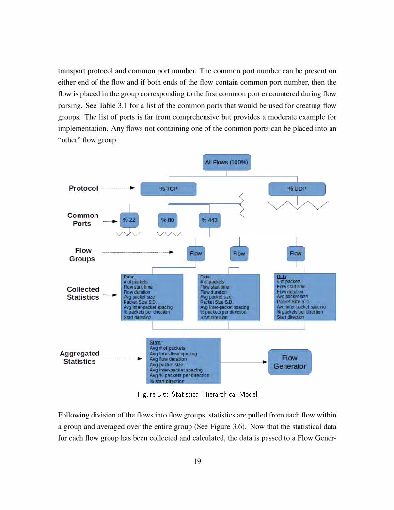
transport protocol and common port number. The common port number can be present oneither end of the flow and if both ends of the flow contain common port number, then theflow is placed in the group corresponding to the first common port encountered during flowparsing. See Table 3.1 for a list of the common ports that would be used for creating flowgroups. The list of ports is far from comprehensive but provides a moderate example forimplementation. Any flows not containing one of the common ports can be placed into an“other” flow group.
Figure 3.6: Statistical Hierarchical Model
Following division of the flows into flow groups, statistics are pulled from each flow withina group and averaged over the entire group (See Figure 3.6). Now that the statistical datafor each flow group has been collected and calculated, the data is passed to a Flow Gener-
19
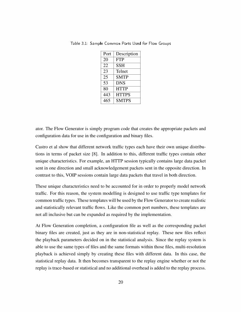
Table 3.1: Sample Common Ports Used for Flow Groups
Port Description20 FTP22 SSH23 Telnet25 SMTP53 DNS80 HTTP443 HTTPS465 SMTPS
ator. The Flow Generator is simply program code that creates the appropriate packets andconfiguration data for use in the configuration and binary files.
Castro et al show that different network traffic types each have their own unique distribu-tions in terms of packet size [8]. In addition to this, different traffic types contain otherunique characteristics. For example, an HTTP session typically contains large data packetsent in one direction and small acknowledgement packets sent in the opposite direction. Incontrast to this, VOIP sessions contain large data packets that travel in both direction.
These unique characteristics need to be accounted for in order to properly model networktraffic. For this reason, the system modelling is designed to use traffic type templates forcommon traffic types. These templates will be used by the Flow Generator to create realisticand statistically relevant traffic flows. Like the common port numbers, these templates arenot all inclusive but can be expanded as required by the implementation.
At Flow Generation completion, a configuration file as well as the corresponding packetbinary files are created, just as they are in non-statistical replay. These new files reflectthe playback parameters decided on in the statistical analysis. Since the replay system isable to use the same types of files and the same formats within those files, multi-resolutionplayback is achieved simply by creating these files with different data. In this case, thestatistical replay data. It then becomes transparent to the replay engine whether or not thereplay is trace-based or statistical and no additional overhead is added to the replay process.
20
3.4 The Process – Segment 2Segment 2 of the system is where the actual traffic replay takes place. Although this replaycannot be conducted without first completing Segment 1, it can be completed as manytimes as desired on the same data set without having to re-run Segment 1. This section willdiscuss the major design and implementation choices for Segment 2.
3.4.1 Threading ConsiderationsInitial drafts of the design called for a single thread for each flow within the playback.While this facilitated proper intra-flow sequencing it did not allow for inter-flow sequenc-ing. Essentially, each flow would replay in order but the order of the flows themselvescould not be guaranteed. Thus the design was simplified to only two threads; one for send-ing packets and one for receiving packets. By implementing such a simple algorithm, theorder of the packet capture can be maintained, providing both proper intra-flow and properinter-flow sequencing.
Thread StructureThe design uses a single thread for building packets, a single thread for sending packets,and another for receiving packets. The receiving thread simply acts as a “sniffer” thatlistens for packet arrival on the specified network interface. The main source for the snifferis the libcrafter documentation [9]. Once a packet is received, the sniffer places a copy ofit into a queue. See Section 3.4.2 for details about the queue.
The ability to place limitations on the packets that the sniffer acts on is vital to properoperation. The sniffing methods of libcrafter allow for this by implementing a filter stringin TCPDUMP format [10]. The filter used for this system is:
" t c p o r udp and inbound "
Without this filter, the sniffer would detect and low level requests submitted by the OS aswell as each of the sent messages.
The receive thread has the capability of examining the received packet for certain charac-teristics but including this functionality during playback will most likely have a negative
21
impact on performance. The capability does exist, though, for debugging and testing pur-poses.
The send thread handles creating the packet to be sent from the data contained in the con-figuration file as well as any associated binary file. Once the packet is created, the sendthread ensures the proper conditions are met before sending the newly created packet overthe wire. This process is discussed in greater detail later in this Section.
The packet building thread is designed to remove work from the time sensitive sendingthread. This building thread reads the configuration file to determine the order of packets,then buildings one packet at a time, in order, by reading the corresponding binary file andplacing the newly created packet into a FIFO queue.
Life Of The ThreadsThe first thread created is the packet building thread. The reasoning behind this is thatthe packet building cannot happen late, but can happen as early as possible to ensure thatpackets are available for the sending thread.
The receive thread is then created by the main thread after all initial global configurationhas been completed. The receive thread is set to listen on the main Ethernet interface (eth0),which includes any virtual interfaces that may exist on the device.
Following the creation of the receive thread, the main program thread then acts as the sendthread. This send thread begins reading the configuration file and examines the file one lineat a time to determines if the current packet is to be sent or received by the local node. Thisis determined by examining the MAC addresses listed in the packet line. If the packet isto be received then the thread checks the queue that holds the received packets. If a packetis there, the send thread then moves on to the next line, which may be another packet tobe received or one to be sent. If the current packet being examined is one to be sent, thesend thread creates the packet and sends it at the appropriate time. The timing details arediscussed in depth in Section 3.4.3.
This process repeats itself until all lines in the configuration file have been read, at whichpoint the receive thread is terminated and the program exits. In short, one thread receivespackets and places them into a queue while the other thread follows the configuration file
22
line by line, sending packets or popping them from the queue as dictated by the file.
3.4.2 The QueueIn order for the send and receive threads to communicate about which packets have beenreceived, a first-in first-out (FIFO) queue is used to store all received packets. Each packetreceived by the sniffer gets pushed onto the queue and each time the configuration filespecifies a packet is to be received before progressing, a packet gets popped from the queue.
In order to maximize efficiency, retain accuracy, and limit unused CPU cycles in a multi-threaded environment, a custom, light-weight queue class was implemented that containedonly the required features and as little use of thread locks as possible. Due to the slowperformance of locks, they were only included in the queue class on shared data structureaccess. Access to the queue not susceptible to multi-threading inconsistencies is performedwithout locks. This custom queue class was originally created by Justin Rohrer and is usedhere with only slight changes.
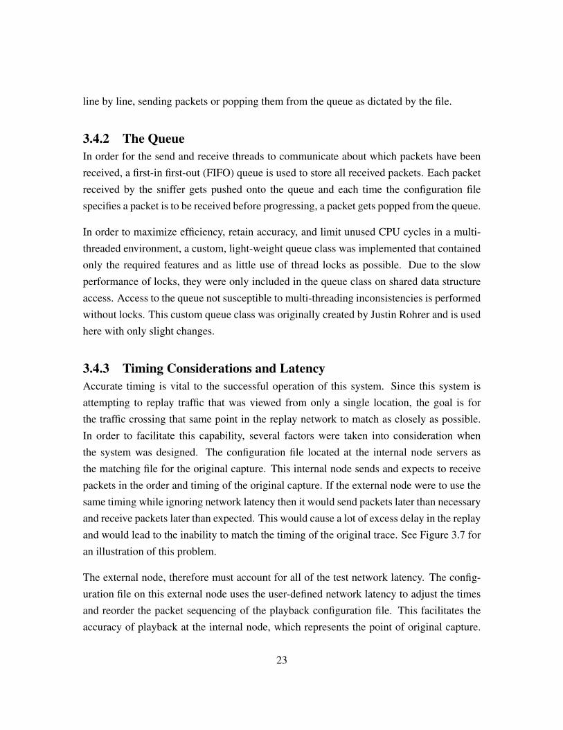
3.4.3 Timing Considerations and LatencyAccurate timing is vital to the successful operation of this system. Since this system isattempting to replay traffic that was viewed from only a single location, the goal is forthe traffic crossing that same point in the replay network to match as closely as possible.In order to facilitate this capability, several factors were taken into consideration whenthe system was designed. The configuration file located at the internal node servers asthe matching file for the original capture. This internal node sends and expects to receivepackets in the order and timing of the original capture. If the external node were to use thesame timing while ignoring network latency then it would send packets later than necessaryand receive packets later than expected. This would cause a lot of excess delay in the replayand would lead to the inability to match the timing of the original trace. See Figure 3.7 foran illustration of this problem.
The external node, therefore must account for all of the test network latency. The config-uration file on this external node uses the user-defined network latency to adjust the timesand reorder the packet sequencing of the playback configuration file. This facilitates theaccuracy of playback at the internal node, which represents the point of original capture.
23
Figure 3.7: Playback Without Latency Factored In
This timing adjustment and configuration file reordering is completed by the external nodeprior to the start of playback so as not to hinder system performance.
Lead TimeFor packets that get sent from a node, the main thread creates these packets as early asfeasible in order facilitate being sent at the exact time period listed in the configuration file.The timing used both in the pcap files and from the system is recorded to the microsecondlevel. Any timing differences less than one microsecond are not recorded or differentiated.If two or more packets in the original pcap file were recorded with the same timestamp,they will be replayed in the order recorded without any wait. That being said, there will besome delay due to the processing overhead of reading the configuration file and creatingthe packet.
Locks and Process PriorityIt is tested and documented that accuracy of wake times from wait and sleep locks cannotbe guaranteed [1]. Although a thread may be put to sleep for a set number of milliseconds,
24
the lock mechanism cannot guarantee that the thread will wake up exactly when this time isup, as the system resources may be dedicated to other processes. Since the system requiresas much time precision as possible, locks are not used to implement wait period based ontime. Instead, the custom queue class uses a wait and notify system when the sendingthread is waiting for a packet to arrive. If the queue is empty, the sending thread waits ona mutex, then when a packet arrives, the receiving thread notifies the sending thread and itgoes back to work.
In order to maximize the accuracy of this cycle, both the sending and receiving threads arerun at the highest real-time priority allowed by the operating system. This minimizes thepotential interruption by other processes during the wait-notify cycle by removing resourcesharing with lower priority processes.
3.4.4 Lost and Malformed PacketsThis system is designed for use in test environments that have a low probability of packetloss or packet corruption. This lack of loss or corruption cannot be guaranteed, however, someasures were implemented to accommodate lost or malformed packets. When malformedpackets are sent to a node, the sniffer, more times than not will not record them as beingreceived. Because of this limitation, malformed packets need to be treated the same asmissing packets with regards to program flow and continuation.
The simple solution for this potential problem was to implement a timeout for each waitperiod. If the send thread is waiting to receive a packet and it is lost or malformed, the sendthread will only wait a specified amount of time before skipping the packet and movingon. In the designed scenario where playback consists of thousands of packets, skippinga few lost or malformed in a test environment will have minimal impact and will allowthe majority of the replay to maintain sequence and timing accuracy. For testing deviceslike intrusion prevention systems, however, if the lost or malformed packets are part of keyintrusion flows, this may provide incorrect results.
During replay, the number of skipped packets will be tracked and at the end of the replay,the program will display the number of missed packets for user information purposes. Thesystem will be unable to determine the difference between a lost packet and a malformedpacket so only a single record of skipped packets will be tallied and displayed to the user.
25
3.4.5 Port Numbers, IP AddressesMaintaining the IP addresses and port numbers from the original network capture is vitalunder certain testing environments, such as WAN testing. Since most capture files willcontain traffic between many IP addresses to and from many port numbers, a method wasneeded for maintaining these various addresses and ports while still sending traffic backand forth between the two nodes. Since each network node is being emulated by actualhosts, he design needed to work around the IP address and port requirement of the typicalhost sockets. As mentioned is Section 4.2, this was accomplished through the use of rawsockets. The use of raw sockets meant that the ip addresses and port number could bemanually supplied, and thus retain the original values.
As can be seen in Figure 3.1, each router has many computers connected to it, forwardingtraffic through it to the computers connected to the other router. Since each node in thistest system is emulating one of these router-like devices, each node must emulate all ofthe computers in the network attached to it. Utilizing raw sockets and manually setting IPaddresses and port numbers allows for this. The main reason this system can take advantageof this design is because the packets are not handled by software on the nodes, other thanthe sniffer, thus making port numbers obsolete. Additionally, since all traffic is being sentfrom a single host to another single host, the only required addresses to accomplish this areMAC addresses. This allows for each packet to have any IP address and still reach the nexthost. If the test environment requires routing to be performed between the two test hosts,then further development will be required.
3.4.6 User Configuration ChoicesMultiple configuration options are available to the user of the system. Many of these op-tions have been discussed in preceding sections, but the complete list of user configurableoptions are listed below along with the sections they are discussed.
1. Statistical replay or trace-based replay (Section 3.3.4).
2. Start and Stop times: The user is given the option to choose when to begin and whento end the emulation. If trace-based replay is chosen then the emulation will end at thestop time or when all packets have been sent, whichever occurs first. If statistical replay ischosen, the emulation will only end at the user supplied stop time.
26
3.5 The DeliverableThe final product delivered to MCTSSA was required to be complete and to meet certaincriteria. Although no specific timing or accuracy goals were set, usability goals were.
MCTSSAs first listed requirements was for the system to be user friendly. All though thetechnical knowledge of the target users is high, MCTSSA desired the system be easy to setup, configure, and use. This is the primary reason for including a graphical user interfaceand simple instructions.
The next requirement placed by MCTSSA was for the system to be “plug-and-play” whichmeans they want the setup and configuration of the system to be as simple fast as possible.Due to the many parts of this system, to include a configured database, four individualprograms, as well as a specific operating system, the decision was made to design thesystem into a virtual machine.
This virtual machine, with all required software pre-installed and pre-configured, is thedeliverable product. By providing the virtual machine, users will simply need to install themachine onto any hypervisor or virtual machine emulator to begin using the system.
3.5.1 The Virtual MachineThe virtual machine comes pre-packaged with all necessary software installed and precon-figured. Additionally, all software and libraries included in the virtual machine is open-source or releasable under the General Public License [11].
The virtual machine is based on the Linux distribution Ubuntu 14.04 LTS. Ubuntu is one ofthe most popular and most supported Linux distributions available. Additionally, version14.04 is the latest version so the operating system within the virtual machine should berelevant for several years before needing updating.
The software requirements for this system, other than the operating system, include a com-plete MySQL database, C++ developer tools and the libraries utilized in the developmentof the system (Boost and Libcrafter), and Wireshark for analyzing network traffic.
All operating system and software configuration has been completed on the virtual ma-chine, requiring no pre-configuration by the user beyond installing the virtual machine.
27
This pre-configuration includes user accounts and permission settings, database configura-tion, C++ developer tools, and operating system configurations.
In order to enhance performance and the replay system, the operating system was pre-configured to run in a much more minimal state than it installs in. This was accomplishedby uninstalling and disabling software not necessary for system operation. Additionally,resource intensive features such as visual window transitions were also disabled. The endresult is a more efficient version of Ubuntu 14.04 while still retaining the required featuresand usability.
28
CHAPTER 4:
Implementation
This chapter discusses the important details of implementing the methodologies discussedin Chapter 3. Most of these details are not vital to understanding how the system accom-plishes its given tasks but they are important for anyone that desires to expand or modify thedesign. This chapter will discuss the programming languages and libraries, any additionalsoftware requirements, as well as the limitations of the system.
4.1 Language ChoiceBuilding on the previous thesis [4], this project initially implemented Python 2.7 for pcapfile inspection, database management population, and file creation. The main reason toutilize Python 2.7 was to use the existing deep packet inspection library DPKT [12]. Otherpacket inspection libraries exist but the decision to leverage off of the work already com-pleted outweighed the potential benefits of other languages. Another consideration whenchoosing to utilize Python is the efficiency of an interpreted language versus a compiledlanguage. Since Python is only used for Segment 1, performance is not a vital issue sincethis segment only performs non time critical pre-processing.
In contrast with using Python 2.7 for Segment 1, C++ was chosen for Segment 2 duealmost entirely to performance considerations. Segment 2 desires highly accurate timingwhich requires the performance that may only be achieved through a compiled language.Not only does Python 2.7 contain limitations on true multi-threading capability [13], it alsodoes not provide for scalability due to the performance difference between compiled andinterpreted languages [14]. The C++ implementation relied on the BOOST [15] librariesfor both thread and timing support, as well as the libcrafter [9] library for reading, creating,and sending packets.
Once work on Segment 2 began, it quickly became apparent that switching back and forthbetween the C++ code in Segment 2 and the python code in Segment 1 wasted a lot of timesince the periods in between the switches were large enough that the familiarity with thelanguage needed refreshing. Additionally, it was discovered that the Python DPKT library
29
did not support all of the packet details required from trace-based replay. For these tworeasons, Segment 1 was re-written in C++, utilizing the libcrafter library.
4.2 Library Usage4.2.1 C++ Boost Thread LibraryThe Boost [15] libraries were chosen for threading implementation mainly due to theirmaturity and the availability of documentation and support. The Boost thread library alsoincludes mature support structures such as thread-safe container, MUTEXs, and locks.
4.2.2 C++ Crafter LibraryThe Crafter library (libcrafter) is utilized for creating, sending, and receiving packets [9].The library has built-in support for creating sockets but it has limitations. Utilizing thisfeature would restrict the packets to higher layers only, and the system requires packetconstruction from the Ethernet layer up. In order to maintain the integrity of the originalpacket data and to manually direct the MAC address of the source and destination nodes,raw sockets are manually created and the Crafter libraries sent and received through thesesockets.
4.3 Database SoftwareThe system was originally designed to use the relational database provided by the Ora-cle XE suite. Unfortunately, the Oracle XE suite has a limit to the allowed size of eachdatabase. In order to be scalable, the project had to switch to the MySQL database suite.The programs that access the database use the MySQL C++ connector, provided by Oracle,and the supplied methods and libraries.
4.4 Flow GeneratorChapter 3 discusses the use of the Flow Generator to convert the captured statistical datainto packets and configuration data based on specific flow templates. These flow templatesare designed to create replay flows based on unique characteristics of different types of traf-fic, such as HTTP and VOIP. This initial version of the replay system does not implementthis design in its entirety. Instead, it implements limited traffic types, which are used toset a baseline for and show how a statistical modelling replay can be accomplished. More
30

precisely, only two templates are initially implemented; one for HTTP (TCP) traffic andone for VOIP (UDP) traffic. The VOIP template only incorporates the VOIP data packetsand omits the SIP packets. When the number of TCP and UDP flows is determined for theuser-specified repay time, the system implements HTTP flows for each required TCP flowand VOIP flows for each required UDP flow. The other traffic variables such as inter-packetspacing, number of packets per flow, and start direction of flows (in or out of the internalnode) are all generated using statistical data from the original trace.
4.5 LimitationsIPv6 SupportDue to time constraints and the fact that most networks have not implemented IPv6, thesystem only supports IPv4 traffic during replay. IF the recorded traffic in the pcap file con-tains IPv6 traffic, those packets will be inserted into the database and organized in the samemanner as the IPv4 traffic. However, IPv6 packets are not included in the configuration filecreation, nor in the traffic replay.
DocumentationAs a standalone system, much more thorough technical documentation could be providedwith the system to describe how its functionality. In lieu of proper technical documentation,this thesis serves to accurately describe all working portions of the system. Along with thisthesis, the system code is well commented and minimal user instructions are provided inelectronic format.
No Deep Packet InspectionAlthough the system testing included inspection and comparison of application data foraccuracy verification, this inspection and verification was completed using an external ap-plication. This system itself contains no deep packet inspection capability to verify thecorrectness of application layer data. This limitation is by design since deep packet in-spection would require not only more compute time, negatively effecting the timing per-formance, but also an extensive library of all of the most used application layer formats.This capability was not deemed necessary to proper functioning of the system so it was notincluded.
31
No Packet Error DetectionAlthough seriously malformed packet will not be processed by the sniffer, mild packeterrors will be and there is no error detection included to catch this. Once again, the reasonfor not including this is to maximize timing performance. Corrupt packets do have theability to effect the results of items being tested in the test environment, such as WANoptimizers, but the risk for corrupted packets in a test environment is low enough to notinclude any detection or correction, other than for testing purposes.
The corrupt packets mentioned here refer typically to corruption that either happens duringpacket transmission or corruption that was replicated from the original capture. There isa small chance that corruption could occur when creating the packet binary files or whenre-creating the packet from those binary files, but no such corruption has been witnessedduring the testing of this system.
Two Node DesignCurrently, the system is only designed to emulate traffic flowing between two networknodes. There are certainly environments were traffic can be recorded travelling betweenmore than two nodes but this support would need to be added to the system. This will befurther discussed in the future work section.
Cannot handle Encrypted PacketsSome traffic capture files may contain encrypted packets. Since the encryption is not knownby the system, these packets are unable to be processed properly and therefore may not bereplayed like the non-encrypted packets. If the encryption only applies to the applicationlayer data, then the packets will be replayed accurately, but if the transport or lower layersare encrypted, then the system has no method for examining the network and transport data,which is essential. Without a comprehensive collection of encrypted packets to evaluate,it was not possible to accurately determine the behavior of the system when encryptedpackets are encountered.
No Built-in Support for Emulating Network Bandwidth LimitationsConsideration was given to incorporating a network bandwidth emulator into the system,but MCTSSA eliminated the requirement due to existing capabilities of their test systems.
32

Due to the lack of desire for this capability, it was not included in the system and duringreplay the system will utilize the full bandwidth of the test environment.
Database/Storage LimitationsDue to the fact that this system loads the packet specifics into a database, it is possiblethat certain test environments where this virtual machine (VM) may run could have limitedresources. If the VM is not provided enough storage space for the database and the packetbinary files, then the system will not be able to complete the capture analysis. This scenariois not tested so the results of this limitation are unknown.
Jumbo FramesJumbo frames are Ethernet frames that exceed the standard maximum segment size of 1500bytes [16]. Due to the rarity of jumbo frames, no support for them was included in thesystem. The database field for holding the packet payload is limited to approximately 1500bytes. The behavior off attempting to insert a jumbo frame into the database is unknown asit was not tested.
Ethernet Interface SpeedDuring testing, it was determined that, due to the unique constraints placed on the systemdesign by the nature of the capture source and location, the speed of the network interfacecard (NIC) played a large role in the accuracy of the system timing. Because of this, it isrecommended that the playback system have a faster connection than the original capturenetwork, if possible. The reason for this, is because the faster connection helps to alleviatesome of the overhead inherent in the emulation system. If a specific network latency isdesired, then it should be implemented using an external system, somewhere in the singletest link while retaining the perceived connection speed of each NIC.
Snap LengthSnap length is a setting within some traffic recording products such as Wireshark that allowsa user to specify a maximum amount of data to record per packet. Essentially, in order toreduce the size of a trace file, a user can limit how much data is maintained from theobserved packets. Since the payload size as well as the actual payload data is necessaryfor the trace-based and statistical playback features of this system, any trace records with areduced snap length are not guaranteed to produce accurate results.
33

THIS PAGE INTENTIONALLY LEFT BLANK
34
CHAPTER 5:
Testing and Evaluation
This chapter will discuss the specifics of testing the system to include what hardware andsoftware was used for the system testing, how the testing environment was optimized, howthe tests were conducted, and how the results were gathered. For the actual testing resultssee Chapter 6.
5.1 The Test Environment5.1.1 Testing MachinesThe replay system was testing using two standard computers, one desktop and one laptop,running Ubuntu 14.04 LTS, connected together via Ethernet cable. The laptop used forthe Internal Node possessed an Intel core I7 processor with 8 GB of RAM. The computerused for the External Node possessed and Intel core I5 processor with 8 GB of RAM. Bothcomputers were connected via on-board gigabit Ethernet network interface cards (NICs).
WiresharkThe program Wireshark was used on the host machine to capture and record all sent andreceived network traffic during the network replay. Wireshark provides not only packetcapturing but also packet and flow analysis tools. All sequencing results were gatheredfrom analysis of these Wireshark captures. For timing calculations, the Internal Node wasresponsible for recording the send and receive times instead of Wireshark. The reason forthis is that the programs were run at real-time process priority, which prevented Wiresharkfrom performing packet capture, due to its lower process priority. These two recordingtechniques were tested against each other, prior to gathering data, to verify that they pro-duced the same results.
Network Card SettingsIt was discovered during testing that the on-board network cards in both laptops were, insome cases, combining TCP packets together before either sending them over the wireor before passing them up to the host software, a process called offloading. This causednot only an inaccurate representation of the captured network traffic, but also false testing
35
results due to inaccurate capture data. Since Wireshark was used to determine the accuracyof the network traffic, it needed the ability to see the traffic exactly as its sent over the wire.When the NICs on the testing machines were combining the packets, they were doing sobefore Wireshark had the chance to capture the original traffic. Essentially, there were caseswhere two separate packets were sent over the network, as designed, but the receiving NICwould combine them into one before passing them to the software. Since Wireshark andthis system are software, they are only able to see the combined packets, thus leading towhat appeared to be flaws in the replay.
In order to fix this packet combining problem, either Wireshark would have to be installedon a separate machine that is able to passively monitor the network traffic on the wire,or the NICs had to have this feature disabled. As discussed in the online article “TOE:TCP Offload Engine on NIC & Packet Capture Misinterpretations” [17], the easiest wayto remove this result was to disable the offloading aspects of each NIC. In order to ensurethat no offloading occurred, TCP segmentation offload (tso), generic segmentation offload(gso) and generic receive offload (gro) were all disabled on both NICs.
OptimizationAlthough both test machines were multi-core machines with large amounts of RAM, theystill had the potential to be slowed down by external sources. For this reason steps weretaken to optimize the machine by minimizing loads external to the system being tested. Thesteps taken to optimize each test machine include the following:
1. The laptop was plugged into external power to eliminate power saving features.2. All non-essential processes were terminated.3. WIFI was disabled.4. All programs were run from the command line vice from an Interactive Development
Environment.5. Real-time updates on Wireshark were disabled.6. All threads were run at real-time scheduling priority.
5.2 Packet AccuracyIn order to determine the accuracy of the packets after trace-based replay, the Wiresharkcapture of the test was compared side-by-side with the original capture. Since Wireshark is
36
able to inspect all fields of the packets to include some common or text-based applicationpayloads, this side-by-side comparison proved sufficient for ensuring packet accuracy.
5.2.1 Packet EncryptionThe one area where Wireshark was unable to determine packet accuracy was when applica-tion layer encrypted packets were used. Since it is either very impractical or impossible todecode these packets, there is no way to check the accuracy of the encrypted data. It was as-sumed during testing, however, that if the unencrypted packets were accurately reproduced,then the encrypted packets were as well.
5.3 Sequencing AccuracyThe accuracy of packet sequencing was also tested using side-by-side comparisons withWireshark. Both the original and test captures were compared, line-by-line on moderately-sized samples in order to verify that the exact order of packets was maintained throughoutthe entire replay.
5.4 Timing AccuracyMultiple, various sized capture files were run several times each. The times were comparedto the original capture time, place into spreadsheets and plotted on line charts. Each capturebegins at time 0 and each individual packet time is compared to the corresponding originalpacket then plotted alongside each other.
5.5 Statistical TestingDue to the fact that the statistical testing does not contain an original capture file, thetest capture on Wireshark was compared to the statistical configuration file in order todetermine accuracy of sequencing, timing, and packet details. Since there are no originalpackets with the statistical replay, packet accuracy was only performed in terms of assuringno malformations occurred and that certain characteristics such as socket pair and payloadsize matched the replay specifications.
37

THIS PAGE INTENTIONALLY LEFT BLANK
38
CHAPTER 6:
Validation
System validation requires the examination of several areas of performance. This sectionwill validate the degree to which packet timing, packet accuracy, and TCP sequencing wasmaintained during trace-based replays. Additionally, this section will define TCP seman-tics in terms of sequencing rules and show that this implementation does not violate thoserules under specific replay environments. Lastly, the statistical replay will be shown to pro-duce an accurate statistical model of the original capture file without utilizing any originalpackets.
6.1 SequencingFor this network replay system, maintaining correct TCP semantics only applies whenthe user chooses sequencing accuracy as the replay priority. When timing is chosen asa priority, the latency assumptions discussed here are intentionally changed or ignored,therefore no guarantee of correct packet ordering is provided.
The following pages will formally define correct TCP semantics, explain the traffic replayalgorithm under scrutiny, and prove that this algorithm will maintain these semantics duringnetwork replay by means of retaining the original packet ordering at the recorded node. Tobegin, we will define the variables that will be used in the proof, discuss some key TCPfundamentals, and define correct TCP semantics.
6.1.1 NotationBefore describing the replay system and defining correct TCP semantics, some commonsymbols and variables needs to be defined. Table 6.1 provides a list of all symbols andvariables used throughout this paper.
6.1.2 The Replay AlgorithmFor the purposes of this section, the network traffic replay scheme discussed in this thesiswill be called Time-Ordered Replay. In Time-Ordered Replay, there are two replay nodes,an internal node and an external node. The original network trace is recorded at a point
39
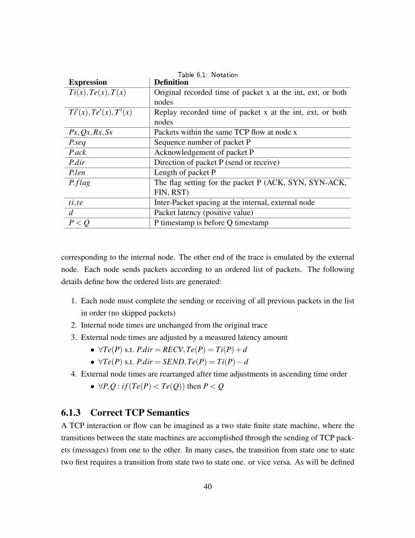
Table 6.1: NotationExpression DefinitionTi(x),Te(x),T (x) Original recorded time of packet x at the int, ext, or both
nodesTi′(x),Te′(x),T ′(x) Replay recorded time of packet x at the int, ext, or both
nodesPx,Qx,Rx,Sx Packets within the same TCP flow at node xP.seq Sequence number of packet PP.ack Acknowledgement of packet PP.dir Direction of packet P (send or receive)P.len Length of packet PP. f lag The flag setting for the packet P (ACK, SYN, SYN-ACK,
FIN, RST)ti, te Inter-Packet spacing at the internal, external noded Packet latency (positive value)P < Q P timestamp is before Q timestamp
corresponding to the internal node. The other end of the trace is emulated by the externalnode. Each node sends packets according to an ordered list of packets. The followingdetails define how the ordered lists are generated:
1. Each node must complete the sending or receiving of all previous packets in the listin order (no skipped packets)
2. Internal node times are unchanged from the original trace3. External node times are adjusted by a measured latency amount
• ∀Te(P) s.t. P.dir = RECV,Te(P) = Ti(P)+d
• ∀Te(P) s.t. P.dir = SEND,Te(P) = Ti(P)−d
4. External node times are rearranged after time adjustments in ascending time order• ∀P,Q : i f (Te(P)< Te(Q)) then P < Q
6.1.3 Correct TCP SemanticsA TCP interaction or flow can be imagined as a two state finite state machine, where thetransitions between the state machines are accomplished through the sending of TCP pack-ets (messages) from one to the other. In many cases, the transition from state one to statetwo first requires a transition from state two to state one. or vice versa. As will be defined
40
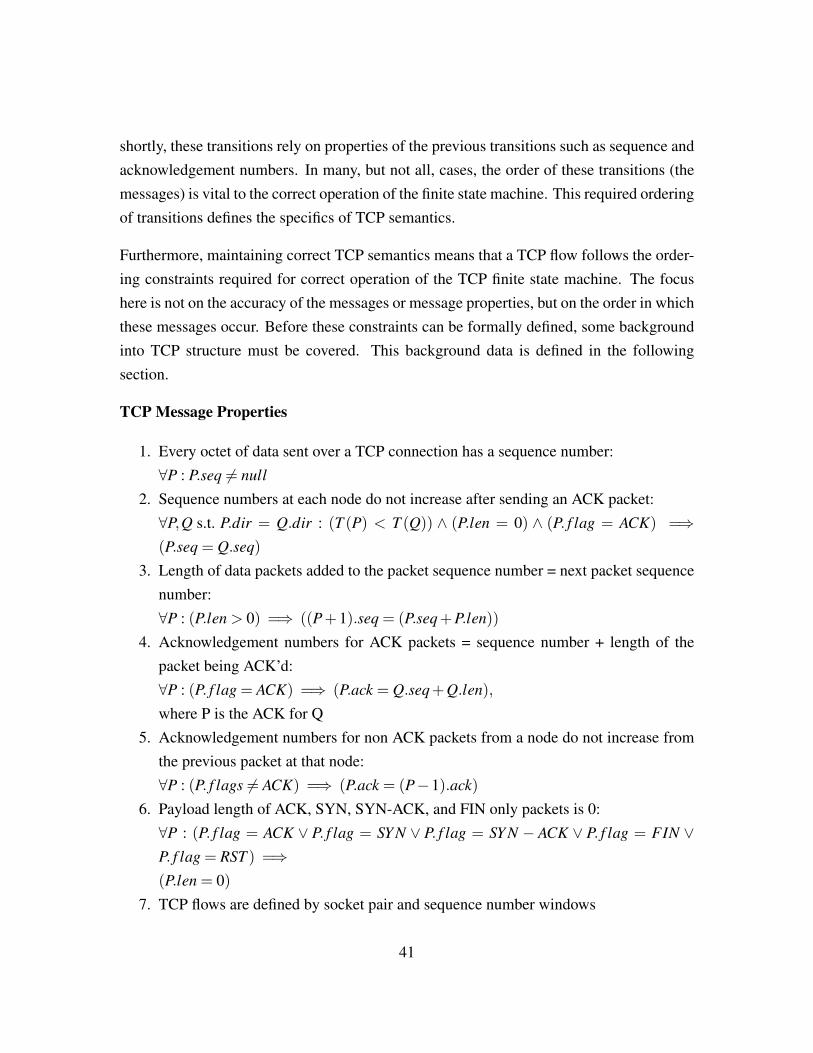
shortly, these transitions rely on properties of the previous transitions such as sequence andacknowledgement numbers. In many, but not all, cases, the order of these transitions (themessages) is vital to the correct operation of the finite state machine. This required orderingof transitions defines the specifics of TCP semantics.
Furthermore, maintaining correct TCP semantics means that a TCP flow follows the order-ing constraints required for correct operation of the TCP finite state machine. The focushere is not on the accuracy of the messages or message properties, but on the order in whichthese messages occur. Before these constraints can be formally defined, some backgroundinto TCP structure must be covered. This background data is defined in the followingsection.
TCP Message Properties
1. Every octet of data sent over a TCP connection has a sequence number:∀P : P.seq 6= null
2. Sequence numbers at each node do not increase after sending an ACK packet:∀P,Q s.t. P.dir = Q.dir : (T (P) < T (Q)) ∧ (P.len = 0) ∧ (P. f lag = ACK) =⇒(P.seq = Q.seq)
3. Length of data packets added to the packet sequence number = next packet sequencenumber:∀P : (P.len > 0) =⇒ ((P+1).seq = (P.seq+P.len))
4. Acknowledgement numbers for ACK packets = sequence number + length of thepacket being ACK’d:∀P : (P. f lag = ACK) =⇒ (P.ack = Q.seq+Q.len),
where P is the ACK for Q5. Acknowledgement numbers for non ACK packets from a node do not increase from
the previous packet at that node:∀P : (P. f lags 6= ACK) =⇒ (P.ack = (P−1).ack)
6. Payload length of ACK, SYN, SYN-ACK, and FIN only packets is 0:∀P : (P. f lag = ACK ∨ P. f lag = SY N ∨ P. f lag = SY N − ACK ∨ P. f lag = FIN ∨P. f lag = RST ) =⇒(P.len = 0)
7. TCP flows are defined by socket pair and sequence number windows
41
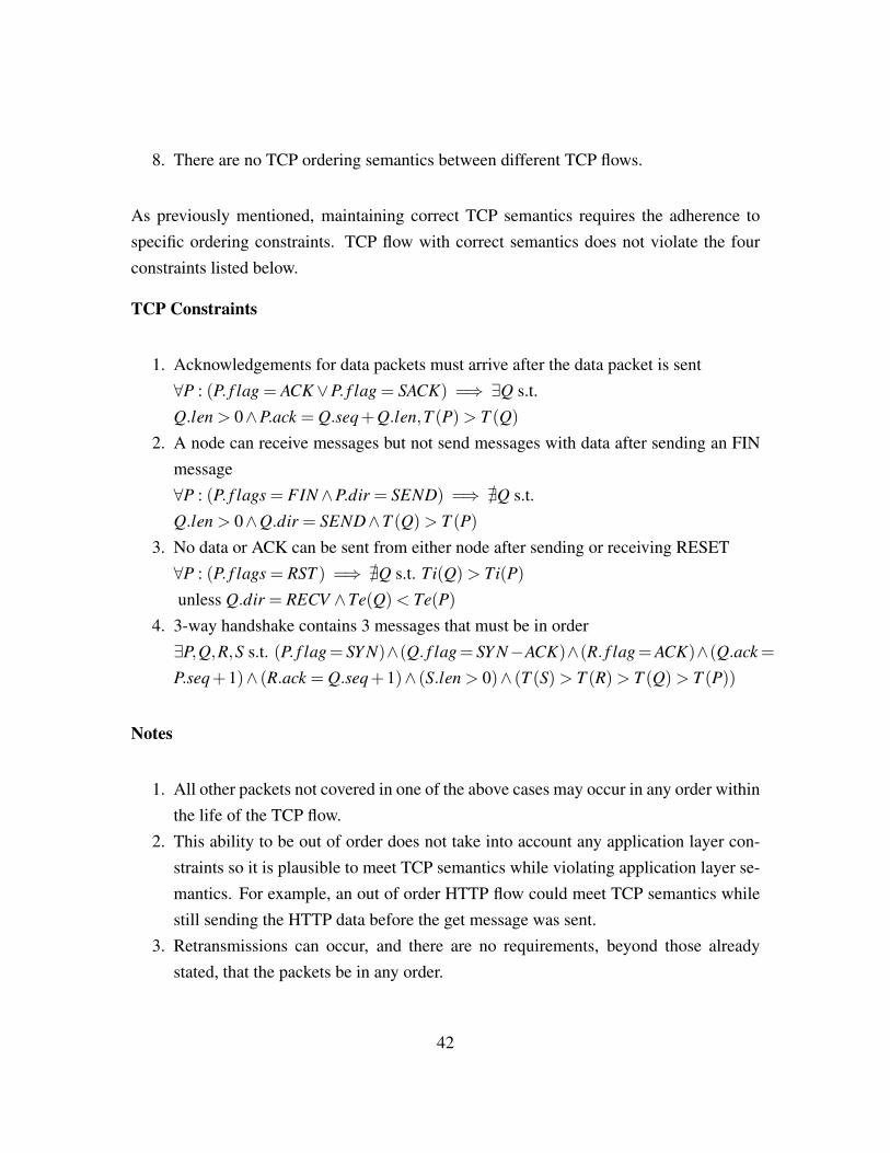
8. There are no TCP ordering semantics between different TCP flows.
As previously mentioned, maintaining correct TCP semantics requires the adherence tospecific ordering constraints. TCP flow with correct semantics does not violate the fourconstraints listed below.
TCP Constraints
1. Acknowledgements for data packets must arrive after the data packet is sent∀P : (P. f lag = ACK∨P. f lag = SACK) =⇒ ∃Q s.t.Q.len > 0∧P.ack = Q.seq+Q.len,T (P)> T (Q)
2. A node can receive messages but not send messages with data after sending an FINmessage∀P : (P. f lags = FIN∧P.dir = SEND) =⇒ @Q s.t.Q.len > 0∧Q.dir = SEND∧T (Q)> T (P)
3. No data or ACK can be sent from either node after sending or receiving RESET∀P : (P. f lags = RST ) =⇒ @Q s.t. Ti(Q)> Ti(P)
unless Q.dir = RECV ∧Te(Q)< Te(P)
4. 3-way handshake contains 3 messages that must be in order∃P,Q,R,S s.t. (P. f lag= SY N)∧(Q. f lag= SY N−ACK)∧(R. f lag=ACK)∧(Q.ack=
P.seq+1)∧ (R.ack = Q.seq+1)∧ (S.len > 0)∧ (T (S)> T (R)> T (Q)> T (P))
Notes
1. All other packets not covered in one of the above cases may occur in any order withinthe life of the TCP flow.
2. This ability to be out of order does not take into account any application layer con-straints so it is plausible to meet TCP semantics while violating application layer se-mantics. For example, an out of order HTTP flow could meet TCP semantics whilestill sending the HTTP data before the get message was sent.
3. Retransmissions can occur, and there are no requirements, beyond those alreadystated, that the packets be in any order.
42
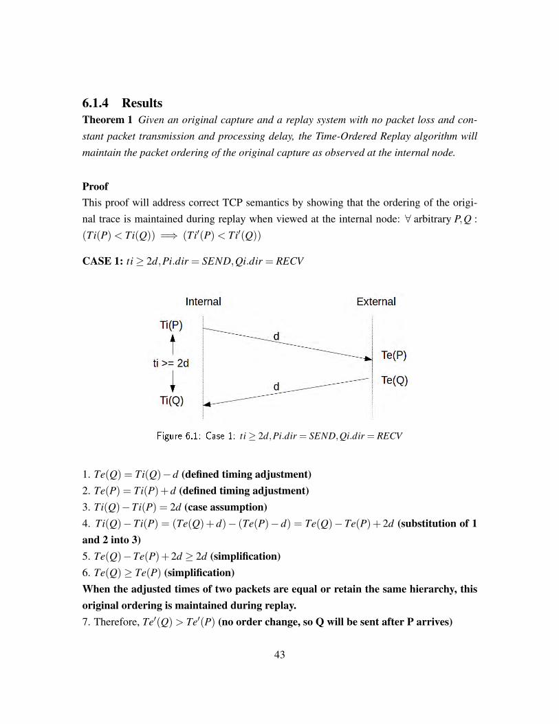
6.1.4 ResultsTheorem 1 Given an original capture and a replay system with no packet loss and con-
stant packet transmission and processing delay, the Time-Ordered Replay algorithm will
maintain the packet ordering of the original capture as observed at the internal node.
ProofThis proof will address correct TCP semantics by showing that the ordering of the origi-nal trace is maintained during replay when viewed at the internal node: ∀ arbitrary P,Q :(Ti(P)< Ti(Q)) =⇒ (Ti′(P)< Ti′(Q))
CASE 1: ti≥ 2d,Pi.dir = SEND,Qi.dir = RECV
Figure 6.1: Case 1: ti≥ 2d,Pi.dir = SEND,Qi.dir = RECV
1. Te(Q) = Ti(Q)−d (defined timing adjustment)2. Te(P) = Ti(P)+d (defined timing adjustment)3. Ti(Q)−Ti(P) = 2d (case assumption)4. Ti(Q)−Ti(P) = (Te(Q)+ d)− (Te(P)− d) = Te(Q)−Te(P)+ 2d (substitution of 1and 2 into 3)5. Te(Q)−Te(P)+2d ≥ 2d (simplification)6. Te(Q)≥ Te(P) (simplification)When the adjusted times of two packets are equal or retain the same hierarchy, thisoriginal ordering is maintained during replay.7. Therefore, Te′(Q)> Te′(P) (no order change, so Q will be sent after P arrives)
43
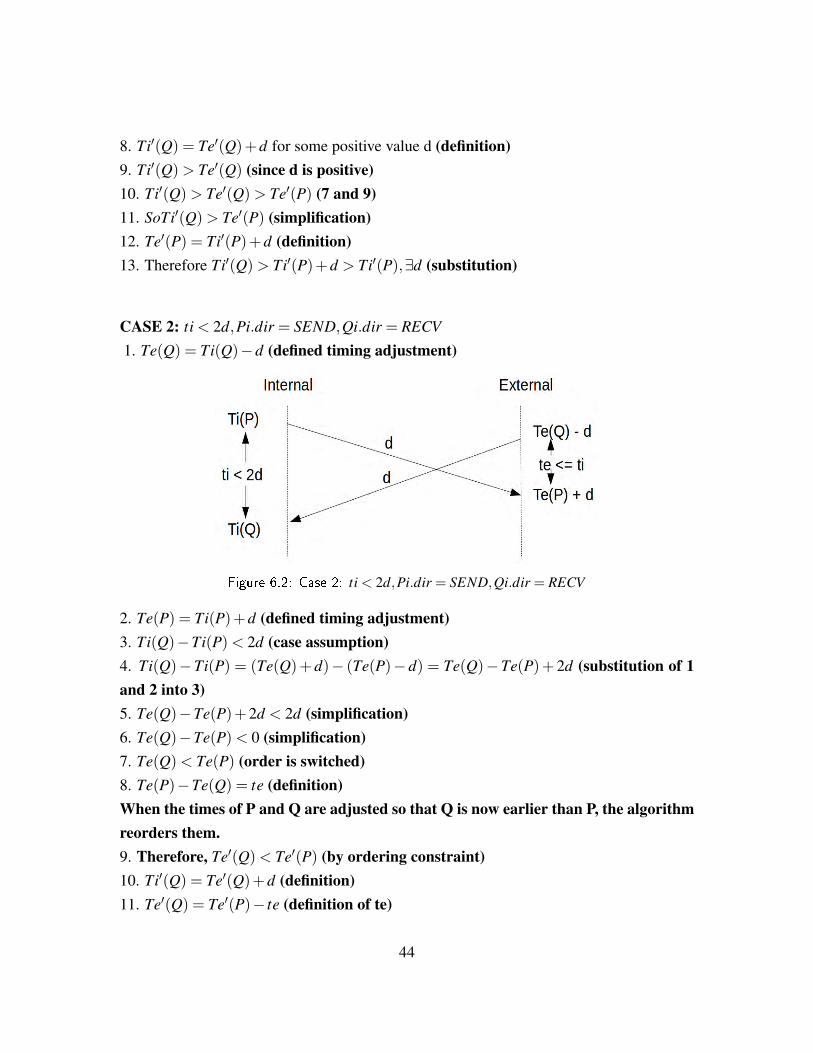
8. Ti′(Q) = Te′(Q)+d for some positive value d (definition)9. Ti′(Q)> Te′(Q) (since d is positive)10. Ti′(Q)> Te′(Q)> Te′(P) (7 and 9)11. SoTi′(Q)> Te′(P) (simplification)12. Te′(P) = Ti′(P)+d (definition)13. Therefore Ti′(Q)> Ti′(P)+d > Ti′(P),∃d (substitution)
CASE 2: ti < 2d,Pi.dir = SEND,Qi.dir = RECV
1. Te(Q) = Ti(Q)−d (defined timing adjustment)
Figure 6.2: Case 2: ti < 2d,Pi.dir = SEND,Qi.dir = RECV
2. Te(P) = Ti(P)+d (defined timing adjustment)3. Ti(Q)−Ti(P)< 2d (case assumption)4. Ti(Q)−Ti(P) = (Te(Q)+ d)− (Te(P)− d) = Te(Q)−Te(P)+ 2d (substitution of 1and 2 into 3)5. Te(Q)−Te(P)+2d < 2d (simplification)6. Te(Q)−Te(P)< 0 (simplification)7. Te(Q)< Te(P) (order is switched)8. Te(P)−Te(Q) = te (definition)When the times of P and Q are adjusted so that Q is now earlier than P, the algorithmreorders them.9. Therefore, Te′(Q)< Te′(P) (by ordering constraint)10. Ti′(Q) = Te′(Q)+d (definition)11. Te′(Q) = Te′(P)− te (definition of te)
44
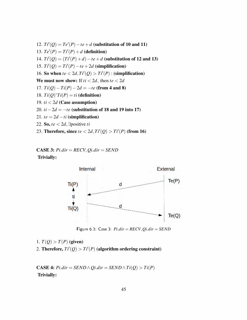
12. Ti′(Q) = Te′(P)− te+d (substitution of 10 and 11)13. Te′(P) = Ti′(P)+d (definition)14. Ti′(Q) = (Ti′(P)+d)− te+d (substitution of 12 and 13)15. Ti′(Q) = Ti′(P)− te+2d (simplification)16. So when te < 2d,Ti′(Q)> Ti′(P) : (simplification)We must now show: If ti < 2d, then te < 2d
17. Ti(Q)−Ti(P)−2d =−te (from 4 and 8)18. Ti(Q)˘Ti(P) = ti (definition)19. ti < 2d (Case assumption)20. ti−2d =−te (substitution of 18 and 19 into 17)21. te = 2d− ti (simplification)22. So, te < 2d,∃positive ti
23. Therefore, since te < 2d,Ti′(Q)> Ti′(P) (from 16)
CASE 3: Pi.dir = RECV,Qi.dir = SEND
Trivially:
Figure 6.3: Case 3: Pi.dir = RECV,Qi.dir = SEND
1. T (Q)> T (P) (given)2. Therefore, Ti′(Q)> Ti′(P) (algorithm ordering constraint)
CASE 4: Pi.dir = SEND∧Qi.dir = SEND∧Ti(Q)> Ti(P)
Trivially:
45
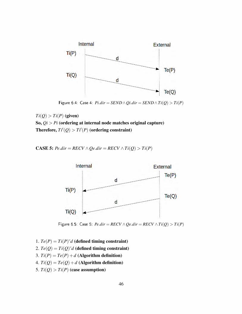
Figure 6.4: Case 4: Pi.dir = SEND∧Qi.dir = SEND∧Ti(Q)> Ti(P)
Ti(Q)> Ti(P) (given)So, Qi > Pi (ordering at internal node matches original capture)Therefore, Ti′(Q)> Ti′(P) (ordering constraint)
CASE 5: Pe.dir = RECV ∧Qe.dir = RECV ∧Ti(Q)> Ti(P)
Figure 6.5: Case 5: Pe.dir = RECV ∧Qe.dir = RECV ∧Ti(Q)> Ti(P)
1. Te(P) = Ti(P)˘d (defined timing constraint)2. Te(Q) = Ti(Q)˘d (defined timing constraint)3. Ti(P) = Te(P)+d (Algorithm definition)4. Ti(Q) = Te(Q)+d (Algorithm definition)5. Ti(Q)> Ti(P) (case assumption)
46
6. Te(P)+d > Te(Q)+d (substitution of 1, 2 and 5)7. Te(P)> Te(Q) (simplification)8. i f (Te(Q)> Te(P)) then Te′(Q)> Te′(P) (ordering constraint)9. Ti′(P) = Te′(P)+d (definition)10. Ti′(Q) = Te′(Q)+d (definition)11. So Ti′(P)−d > Ti′(Q)−d (substitution of 9 and 10 into 8)12. Therefore, Ti′(P)> Ti′(Q) (substitution)
It has now been shown that no matter the sequence of packet direction and timing and givena trace that meets the original assumptions, Time-Ordered Replay maintains the orderingof the original trace as viewed from the internal node. Q.E.D.
Corollary 1 With a given replay algorithm that maintains the ordering of the original trace
and an original trace maintains correct TCP semantics, the replay of this trace also main-
tains correct TCP semantics as viewed at the internal node. Since Time-Ordered Replay
has been shown to maintain this original ordering within the given constraints, then it is
also shown to maintain correct TCP semantics.
6.1.5 ConclusionsGiven the provided definition of TCP semantics and the assumption that the original capturemaintains these semantics, this proof as shown that no matter the sequence of packets, thereplay algorithm Time-Ordered Replay, with an accurately measured and constant latency,maintains these semantics by maintaining the original order of captured packets as seen atthe internal node.
Furthermore, this theorem can be expanded to cover a more general case by relaxing someof the constraints. More specifically, by relaxing the requirement for a constant latencyvalue d, further analysis can show that original trace ordering will still be maintained witha variable latency, as long as that latency is within specific bounds. These bounds couldbe formally derived to provide upper and lower bounds and more accurately model a realnetwork environment where latency is not typically constant.
47

Latency MeasurementsThe latency measurements for these tests were performed manually using ping requestsbetween the two nodes. The average of 20 ping results was used to determine the RTT ofthe test network. The latency value used for the test is half of this measured RTT value. Themanual estimation of latency is simple and allows adaptability to various test networks.
6.2 TimingReproducing timing proved to be the most arduous task during system implementation.Every aspect of the replay program was optimized for performance by performing as muchpre-processing as possible and eliminating unnecessary work such as extra data copying.Despite these optimizations, exactly matching the original packets times while maintainingpacket sequencing was not achieved for high volume capture files.
6.2.1 Replay Timing AccuracySeveral capture files were used in validating timing requirements but only a few exam-ples will be presented here to demonstrate the result accuracy. The implementation led tothree major replay timing environments, each with varying degrees of sequencing accu-racy. As described in Section 6.1, correct sequencing can only be validated for the replayenvironment that uses an accurate measurement of system latency. However, if accuratesequencing is not a priority for the user, then two improved timing environments can beused.
The first test involved a single flow with large packet sizes and a high transfer rate. Ascan be seen in Figure 6.6, the replay environment with the worst timing accuracy wasusing the measured latency without adjustment. When the measured latency is doubled,the performance improves remarkably but still is not able to keep up with the original trace.When accurate sequencing is at a minimum and the replay sends packets purely based onsend times, then the timing is able to be matched almost exactly.
Latency AdjustmentsThe decision to adjust the latency during testing was to help validate the accuracy of themeasured latency as well as to evaluate the effect of a larger latency value on timing ac-curacy. As was discussed in Section 6.1, doubling the latency does not facilitate retain-
48
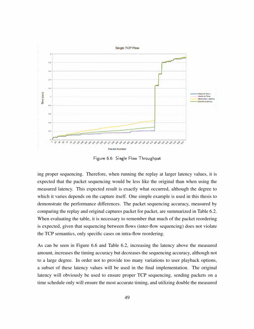
Figure 6.6: Single Flow Throughput
ing proper sequencing. Therefore, when running the replay at larger latency values, it isexpected that the packet sequencing would be less like the original than when using themeasured latency. This expected result is exactly what occurred, although the degree towhich it varies depends on the capture itself. One simple example is used in this thesis todemonstrate the performance differences. The packet sequencing accuracy, measured bycomparing the replay and original captures packet for packet, are summarized in Table 6.2.When evaluating the table, it is necessary to remember that much of the packet reorderingis expected, given that sequencing between flows (inter-flow sequencing) does not violatethe TCP semantics, only specific cases on intra-flow reordering.
As can be seen in Figure 6.6 and Table 6.2, increasing the latency above the measuredamount, increases the timing accuracy but decreases the sequencing accuracy, although notto a large degree. In order not to provide too many variations to user playback options,a subset of these latency values will be used in the final implementation. The originallatency will obviously be used to ensure proper TCP sequencing, sending packets on atime schedule only will ensure the most accurate timing, and utilizing double the measured
49
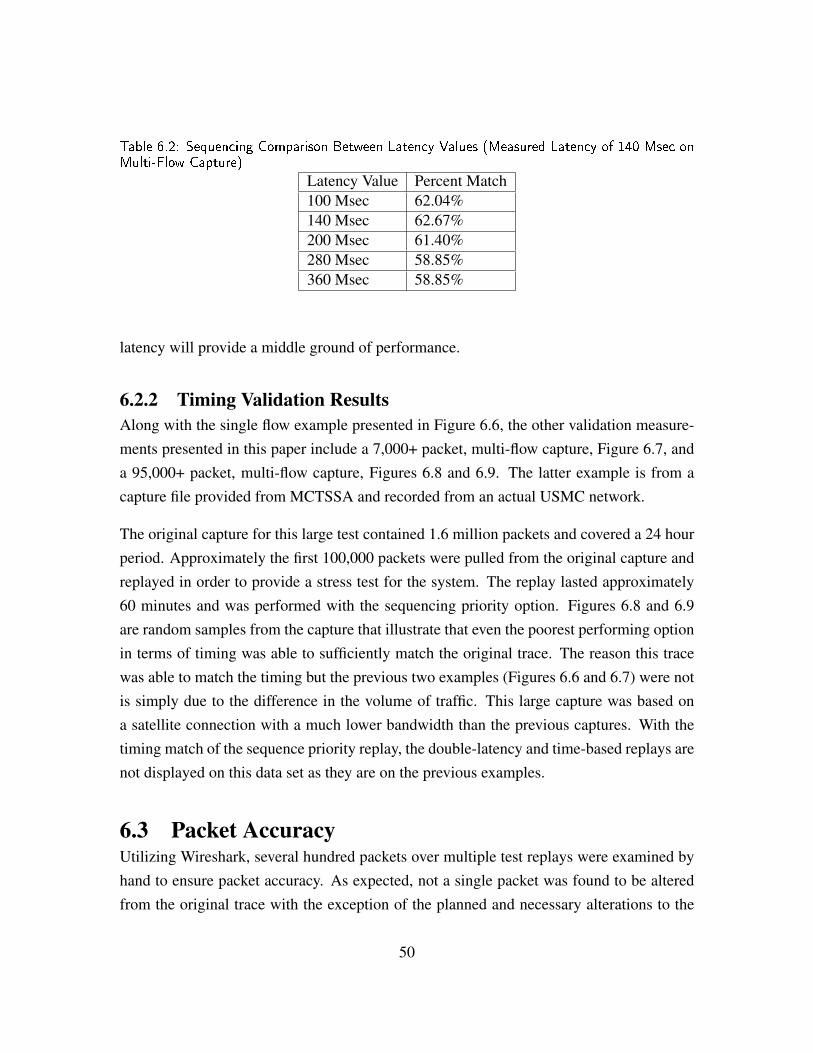
Table 6.2: Sequencing Comparison Between Latency Values (Measured Latency of 140 Msec onMulti-Flow Capture)
Latency Value Percent Match100 Msec 62.04%140 Msec 62.67%200 Msec 61.40%280 Msec 58.85%360 Msec 58.85%
latency will provide a middle ground of performance.
6.2.2 Timing Validation ResultsAlong with the single flow example presented in Figure 6.6, the other validation measure-ments presented in this paper include a 7,000+ packet, multi-flow capture, Figure 6.7, anda 95,000+ packet, multi-flow capture, Figures 6.8 and 6.9. The latter example is from acapture file provided from MCTSSA and recorded from an actual USMC network.
The original capture for this large test contained 1.6 million packets and covered a 24 hourperiod. Approximately the first 100,000 packets were pulled from the original capture andreplayed in order to provide a stress test for the system. The replay lasted approximately60 minutes and was performed with the sequencing priority option. Figures 6.8 and 6.9are random samples from the capture that illustrate that even the poorest performing optionin terms of timing was able to sufficiently match the original trace. The reason this tracewas able to match the timing but the previous two examples (Figures 6.6 and 6.7) were notis simply due to the difference in the volume of traffic. This large capture was based ona satellite connection with a much lower bandwidth than the previous captures. With thetiming match of the sequence priority replay, the double-latency and time-based replays arenot displayed on this data set as they are on the previous examples.
6.3 Packet AccuracyUtilizing Wireshark, several hundred packets over multiple test replays were examined byhand to ensure packet accuracy. As expected, not a single packet was found to be alteredfrom the original trace with the exception of the planned and necessary alterations to the
50
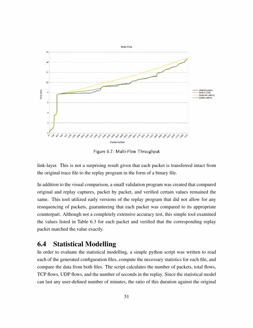
Figure 6.7: Multi-Flow Throughput
link-layer. This is not a surprising result given that each packet is transferred intact fromthe original trace file to the replay program in the form of a binary file.
In addition to the visual comparison, a small validation program was created that comparedoriginal and replay captures, packet by packet, and verified certain values remained thesame. This tool utilized early versions of the replay program that did not allow for anyresequencing of packets, guaranteeing that each packet was compared to its appropriatecounterpart. Although not a completely extensive accuracy test, this simple tool examinedthe values listed in Table 6.3 for each packet and verified that the corresponding replaypacket matched the value exactly.
6.4 Statistical ModellingIn order to evaluate the statistical modelling, a simple python script was written to readeach of the generated configuration files, compute the necessary statistics for each file, andcompare the data from both files. The script calculates the number of packets, total flows,TCP flows, UDP flows, and the number of seconds in the replay. Since the statistical modelcan last any user-defined number of minutes, the ratio of this duration against the original
51
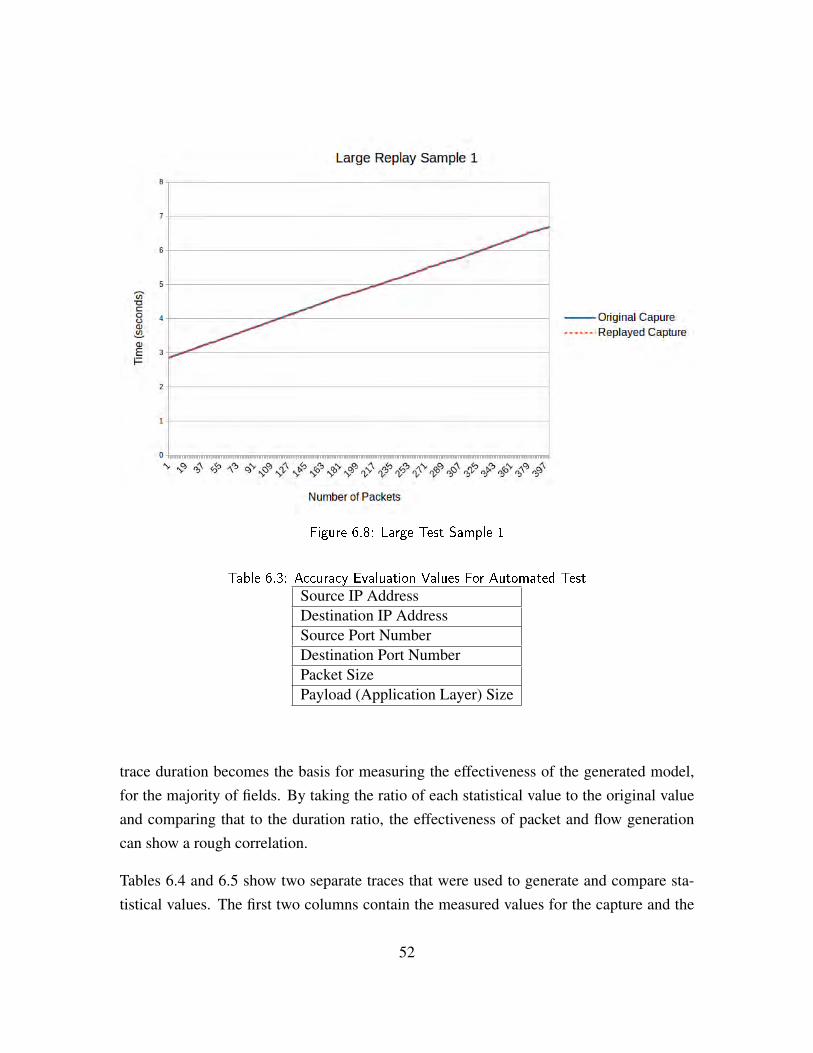
Figure 6.8: Large Test Sample 1
Table 6.3: Accuracy Evaluation Values For Automated Test
Source IP AddressDestination IP AddressSource Port NumberDestination Port NumberPacket SizePayload (Application Layer) Size
trace duration becomes the basis for measuring the effectiveness of the generated model,for the majority of fields. By taking the ratio of each statistical value to the original valueand comparing that to the duration ratio, the effectiveness of packet and flow generationcan show a rough correlation.
Tables 6.4 and 6.5 show two separate traces that were used to generate and compare sta-tistical values. The first two columns contain the measured values for the capture and the
52
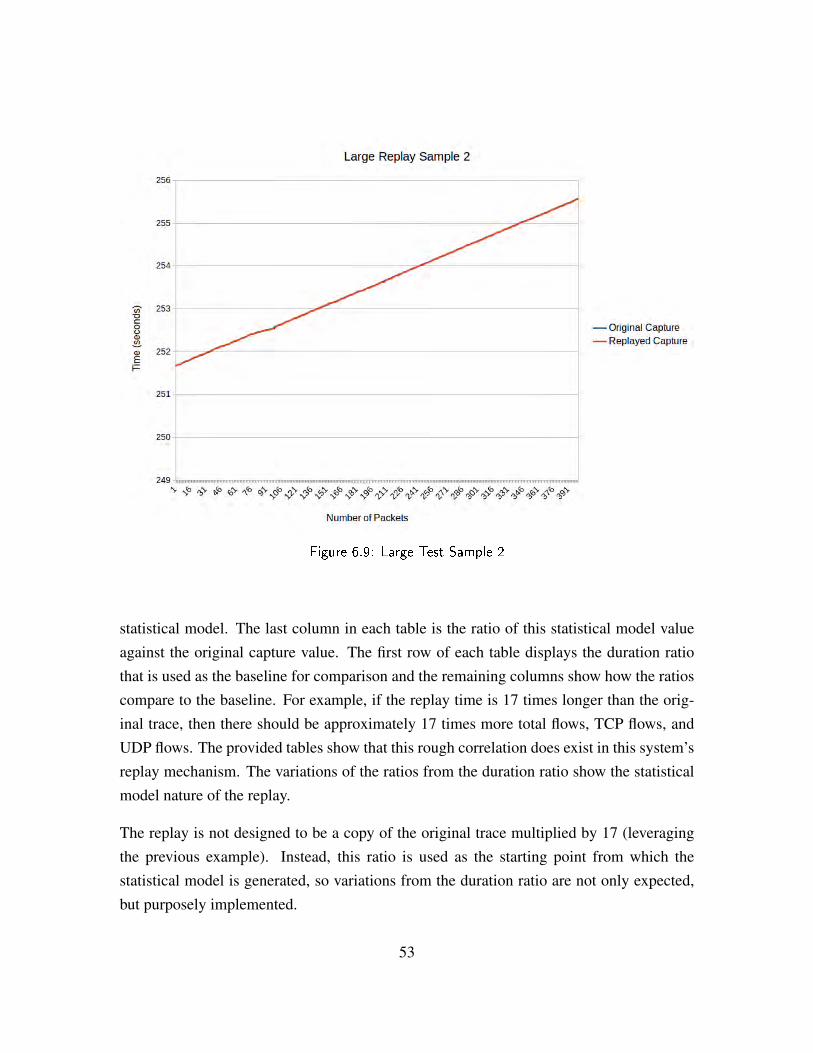
Figure 6.9: Large Test Sample 2
statistical model. The last column in each table is the ratio of this statistical model valueagainst the original capture value. The first row of each table displays the duration ratiothat is used as the baseline for comparison and the remaining columns show how the ratioscompare to the baseline. For example, if the replay time is 17 times longer than the orig-inal trace, then there should be approximately 17 times more total flows, TCP flows, andUDP flows. The provided tables show that this rough correlation does exist in this system’sreplay mechanism. The variations of the ratios from the duration ratio show the statisticalmodel nature of the replay.
The replay is not designed to be a copy of the original trace multiplied by 17 (leveragingthe previous example). Instead, this ratio is used as the starting point from which thestatistical model is generated, so variations from the duration ratio are not only expected,but purposely implemented.
53
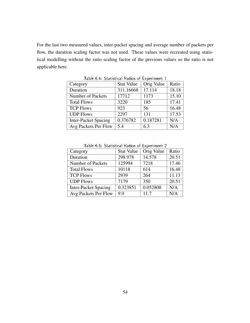
For the last two measured values, inter-packet spacing and average number of packets perflow, the duration scaling factor was not used. These values were recreated using statis-tical modelling without the ratio scaling factor of the previous values so the ratio is notapplicable here.
Table 6.4: Statistical Ratios of Experiment 1
Category Stat Value Orig Value RatioDuration 311.16668 17.114 18.18Number of Packets 17712 1173 15.10Total Flows 3220 185 17.41TCP Flows 923 56 16.48UDP Flows 2297 131 17.53Inter-Packet Spacing 0.376782 0.187281 N/AAvg Packets Per Flow 5.4 6.3 N/A
Table 6.5: Statistical Ratios of Experiment 2
Category Stat Value Orig Value RatioDuration 298.978 14.578 20.51Number of Packets 125994 7218 17.46Total Flows 10118 614 16.48TCP Flows 2939 264 11.13UDP Flows 7179 350 20.51Inter-Packet Spacing 0.323851 0.052808 N/AAvg Packets Per Flow 9.9 11.7 N/A
54

CHAPTER 7:
Conclusion and Future Work
The goal of this thesis was to create a network traffic replay system that incorporates bothtrace-based replay as well as statistical modelling replay in a non-proprietary, plug-and-play environment. The system designed here provides the ability to maintain TCP seman-tics (to be stateful) and recreate initial traffic loads.
Additionally, the system accurately creates an accurate statistical representation of the orig-inal trace that can be used to provide a representative replay over a user-defined amount oftime. By capturing the certain statistical values from the original trace, the system createsthe model to represent the numbers and types of flows, the commonly used ports withinthose flows, as well as the inter-packet and inter-flow spacing. All of this is accomplishedprior to playback in order not to effect replay performance.
The system in not without limitations, though. The increased overhead of handling op-erating system tasks at the application layer proved to be a challenge when attempting tomatch the timing of high density captures. In order to accommodate this short-coming, thesystem provides the user preference of guaranteeing TCP semantics and packet orderingthat more closely resembles the original trace, or more accurate timing at the expense ofpacket ordering and possibly TCP semantics.
7.1 Future WorkThe system developed meets the basic requirements put forth by MCTSSA, but there areseveral areas where expansion would enhance the performance or the possible applicationsof the finished system. Those enhancements are discussed in the following sections.
7.1.1 The InterfaceGraphical user interfaces (GUI), if designed well, are generally more intuitive than com-mand prompt interfaces, especially when users are unfamiliar with the system. By design-ing the user interaction into a GUI vice the command line, the operation of the system willbe much more intuitive as well as less prone to errors created through incorrect or incom-
55
plete user input. The desired result of creating a front end GUI would be increased ease ofuse and decreased implementation time.
This system will benefit greatly from a single graphical front end. The front end wouldsimply link all programs of the system together into a single user interface. From thisgraphical front end, the user can operate all portion of the replay system as well as configureall user settings and enter all user data. The GUI would prevent bad user input into theprograms as well as make the system much more intuitive.
7.1.2 Addition of More NodesThe current implementation only accommodates a network with one internal and one exter-nal node. In order to increase the usability of the system, it should be extended to supportone internal node and multiple external nodes. This could potentially be accomplished us-ing the same two computers by configuring one of the nodes to emulate multiple nodes.Another possible solution would simply be to use computers with multiple NICs and runmultiple instances of the replay system simultaneously. This latter solution would requiresome method for synchronizing the two replay instances together, but may require lessmodification to the original code.
7.1.3 Add IPv6 SupportThe system only partially supports the inclusion of IPv6. The portion that supports IPv6is Segment 1 in Chapter 3. True IPv6 packets, not IPv6 encapsulated packets, are allprocessed and inserted into the database. Once the database is properly populated, the IPv6packet support is complete and the remaining system programs simply ignore the IPv6packets, if any, in the database.
This expansion would require inclusion of the IPv6 packets in the configuration file as wellas the replay engine. This would also require an additional user option to choose betweenan IPv4, IPv6, or a combined replay environment, since they may both exist on the network,even without encapsulation. IPv6 encapsulation is discussed in Section 7.1.4.
7.1.4 Add IPv6 Encapsulation SupportThe database population program currently expects the TCP or UDP layer to come imme-diately after the IP layer. In IPv6 encapsulated packets, the IPv6 layer is immediately on
56
top of the IPv4 layer, with the TCP or UDP layer on top of the IPv6 layer. Access to theTCP/UDP header is mandatory because it provides necessary replay information such asport numbers and sizes. In order to accommodate these encapsulated packets, the Segment1 programs need to be expanded to recognize this extra layer in order to find the dislocatedtransport layer and the required data.
7.1.5 Database Efficiency EnhancementsThe database population procedure inserts a single packet at a time into the database. Thissingle insert requires extra time consuming steps such as erasing server-side cache foreach insert. By utilizing batch inserts where many inserts are completed at once, manyof these steps only need to occure once for each batch instead of once for each packet.Unfortunately, the current implementation of the C++ MySQL API utilized in this programdoes not support batch processing [18].
7.1.6 File I/O Efficiency EnhancementsThe current implementation of the system performs batch processing of binary files whencreating the packets for replay. This batch processing is rudimentary and may not be suf-ficient during very large and high volume replay scenarios. Further refinement, such ascombining multiple packets into each file, could help prevent this potential bottleneck.
7.1.7 Beyond TCP and UDPTCP and UDP traffic encompass the majority of important network traffic in modern net-works. Therefore, this system was designed to only support TCP and UDP. Despite this,system users might desire the ability to reproduce other forms of traffic to possibly includeICMP and proprietary protocols. In order to support message types and protocols otherthan TCP and UDP, both Segment 1 and Segment 2 programs will require updating as thecurrent implementation simply ignores those packets when encountered.
7.1.8 Expand Traffic TemplatesThe current system implementation only includes two traffic templates, one for HTTP(TCP)traffic, and one for VOIP(UDP) traffic. In order to significantly enhance the statistical mod-elling of the system, inclusion of more templates is required. This should begin with the
57
most common traffic types but can be tailored for specific needs that utilize unique traffictypes.
7.1.9 Further Statistical AnalysisIt is difficult to argue against the fact that an entire thesis could be completed on statisticalmodelling of network traffic. This thesis only presents a very basic demonstration of howstatistical replay can be achieved within the frameworks of this replay system. Along withexpanding the traffic templates, some of the other network traffic properties that should beincluded in future drafts include inter-flow spacing and distribution of flows at given timeperiods within the capture instead of averages throughout the whole capture. An exampleof the latter point is being able to identify when a capture contains the majority of flows atthe beginning or end of the capture period, as opposed to evenly distributed throughout.
7.2 ConclusionThe initial goal of attempting to create a network traffic replay system for both trace-basedand statistical replay was met. A compromise was required between timing and sequencingperformance, due to the higher overhead of processing all packets at the application layer.Despite this, both timing and sequencing goals were able to be met, just not simultaneouslyfor traces that contain a high throughput of traffic.
The work completed in this thesis provide a viable product for performing network trafficreplay utilizing non-proprietary software encased inside an easily implemented virtual ma-chine. The original requirements placed by MCTSSA have been met and with some of thepreviously stated enhancements, the usefulness and performance of the system can be evenfurther enhanced.
58

APPENDIX: Source Code
Source code is maintained at the following repository:
https://github.com/homerstf/TrafficReplay
59

THIS PAGE INTENTIONALLY LEFT BLANK
60
List of References
[1] W.-c. Feng, A. Goel, A. Bezzaz, W.-c. Feng, and J. Walpole, “Tcpivo: Ahigh-performance packet replay engine,” in Proceedings of the ACM SIGCOMM Workshop on Models, Methods and Tools for Reproducible Network Research, ser. MoMeTools ’03. New York, NY: ACM, 2003, pp. 57–64.
[2] G. Combs. (2014, October). Wireshark. [Online]. Available: https://www.wireshark.org/
[3] Marine Corps Systems Command about MCTSSA. [Online]. Avail-able: http://www.marcorsyscom.marines.mil/ProfessionalStaff/DCSIAT/MCTSSA/ABOUTMCTSSA.aspx
[4] T. S. Le Vier, “A tool for stateful replay,” M.S. thesis, Computer Science Department,Naval Postgraduate School, 2013.
[5] S.-S. Hong and S. Wu, “On interactive internet traffic replay,” in Recent Advancesin Intrusion Detection, ser. Lecture Notes in Computer Science, A. Valdes andD. Zamboni, Eds. Springer Berlin Heidelberg, 2006, vol. 3858, pp. 247–264.[Online]. Available: http://dx.doi.org/10.1007/11663812_13
[6] J. F. Kurose and K. W. Ross, Computer Networking: A Top-Down Approach, 5th ed.Boston, MA: Addison-Wesley Publishing Company, 2009.
[7] IANA. (2014, November). Transmission control protocol (tcp) parameters. [Online].Available: http://www.iana.org/assignments/tcp-parameters/tcp-parameters.xhtml
[8] E. Castro, I. E. Fonseca, A. Kumar, and M. S. Alencar, “A packet distributiontraffic model for computer networks,” in The International TelecommunicationsSymposium, ITS, 2010.
[9] E. Pellegrino. (n.d.). Libcrafter: A high level library for c++ to generate and sniff networkpackets (version 0.3). [Online]. Available: https://code.google.com/p/libcrafter/
[10] Manpage of tcpdump (version 4.5.1). (n.d.). [Online]. Available: http://www.tcpdump.org/tcpdump_man.html
[11] The gnu general public license v3.0: Gnu project. (n.d.). [Online]. Available:http://www.gnu.org/copyleft/gpl.html
[12] Dugsong. (2015, March). dpkt - python packet creation / parsing library. [Online].Available: https://code.google.com/p/dpkt/
61
[13] Python Wiki globalinterpreterlock. (n.d.). [Online]. Available: https://wiki.python.org/moin/GlobalInterpreterLock
[14] M. P. Bhave and S. A. Patekar, Programming with Java. Delhi, India: PearsonEducation, 2008.
[15] Boost c++ libraries (version 1.55). (n.d.). [Online]. Available: http://www.boost.org
[16] S. Hogg. (2013, June). Jumbo frames: Does your network supportjumbo frames and should you enable it? [Online]. Available: http://www.networkworld.com/article/2224722/cisco-subnet/jumbo-frames.html
[17] S. Pachghare. (2014, November). Toe: Tcp offload engine on nic & packet capturemisinterpretations. [Online]. Available: http://www.thesubodh.com/2012/05/toe-tcp-offload-engine-on-nic-packet.html
[18] MySQL. (2015, February). Chapter 10 mysql connector/c++ usage notes.[Online]. Available: http://dev.mysql.com/doc/connector-cpp/en/connector-cpp-usage-notes.html
62

Initial Distribution List
1. Defense Technical Information CenterFt. Belvoir, Virginia
2. Dudley Knox LibraryNaval Postgraduate SchoolMonterey, California
63