Natural Gas Liquids Recovery. NGL Brochure_tcm136... · + liquids plus the residue gas as fuel is...
12
Natural Gas Liquids Recovery. CRYO-PLUS™ Technology.
Transcript of Natural Gas Liquids Recovery. NGL Brochure_tcm136... · + liquids plus the residue gas as fuel is...

Natural Gas Liquids Recovery.CRYO-PLUS™ Technology.

Natural gas experience.Linde Engineering North America Inc. (LENA) has constructed NGL Plants since 1969 using traditional processes as well as the more advanced CRYO-PLUS™ technology.
CRYO-PLUSTM Proprietary Technology
Higher Recovery with Less Energy Designed to be used in natural gas, or shale gas applications, the patented CRYO-PLUS™ process recovers more ethane and heavier components with less energy required than traditional liquid recovery processes.
Higher Flexibility Enhanced CRYO-PLUSTM is more robust and flexible over a wide range of pressure and feed compositions. This feature is especially important for treatment of wet shale gas, which is known for having large compositional variability over time. CRYO-PLUSTM provides a high level of ethane recovery in ethane recovery mode, and a high level propane recovery in ethane rejection mode. The process can quickly and easily change between the two modes of operation.
Reduced Feed and Product Compression The proprietary process has been optimized to operate more efficiently resulting in lower inlet pressure requirements while still providing the same product discharge pressure.
Reduced Fuel Consumption The CRYO-PLUSTM process requires less power than a typical gas processing plant.
02

04
CRYO-PLUS™
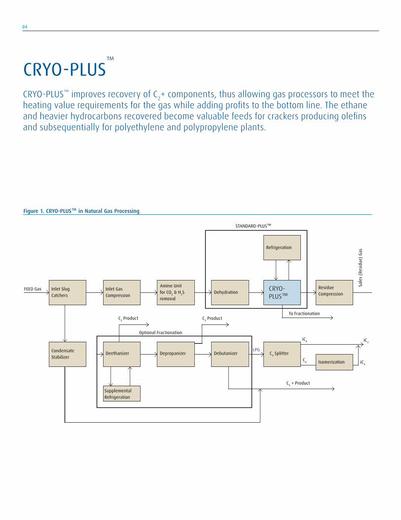
CRYO-PLUS™ improves recovery of C2+ components, thus allowing gas processors to meet the heating value requirements for the gas while adding profits to the bottom line. The ethane and heavier hydrocarbons recovered become valuable feeds for crackers producing olefins and subsequentially for polyethylene and polypropylene plants.
Inlet Slug Catchers
Isomerization
CRYO- PLUS™
Debutanizer Depropanizer
Supplemental Refrigeration
C4 Splitter
Dehydration
Deethanizer
Condensate
Stabilizer
Refrigeration
Residue Compression
Amine Unit for CO2 & H2S removal
Inlet Gas Compression
C5 + Product
C4 iC4
iC4iC4
LPG
Optional Fractionation
C3 ProductC2 ProductTo Fractionation
FEED Gas
STANDARD-PLUS™
Sale
s (Re
sidue
) Gas
Figure 1. CRYO-PLUS™ in Natural Gas Processing

CRYO-PLUS™
To date, LENA has installed several CRYO-PLUS™ Recovery Systems in Natural Gas Processing Plants. The economic payout of these systems can be as low as one year. All of these systems were designed for recovery or rejection of ethane depending on the required mode of operation
Where is CRYO-PLUS™ Used CRYO-PLUSTM is used for processing any type of gas containing hydrocarbon liquids. Traditionally, the gas processing industry have been using Dew Point Control or other technology plants to purify the natural gas to meet pipeline requirements, i.e. prevent liquids formation in pipeline and meet a maximum BTU content. Unfortunately, these systems recover less than 80% of the C2 and some of the C3+ can slip through into the gas. These C2+ liquids may provide for a higher sales value than the pipeline gas by itself. Figure 1 shows a block flow diagram for a typical natural gas processing scheme, and indicates where CRYO-PLUS™ is integrated within the operation.
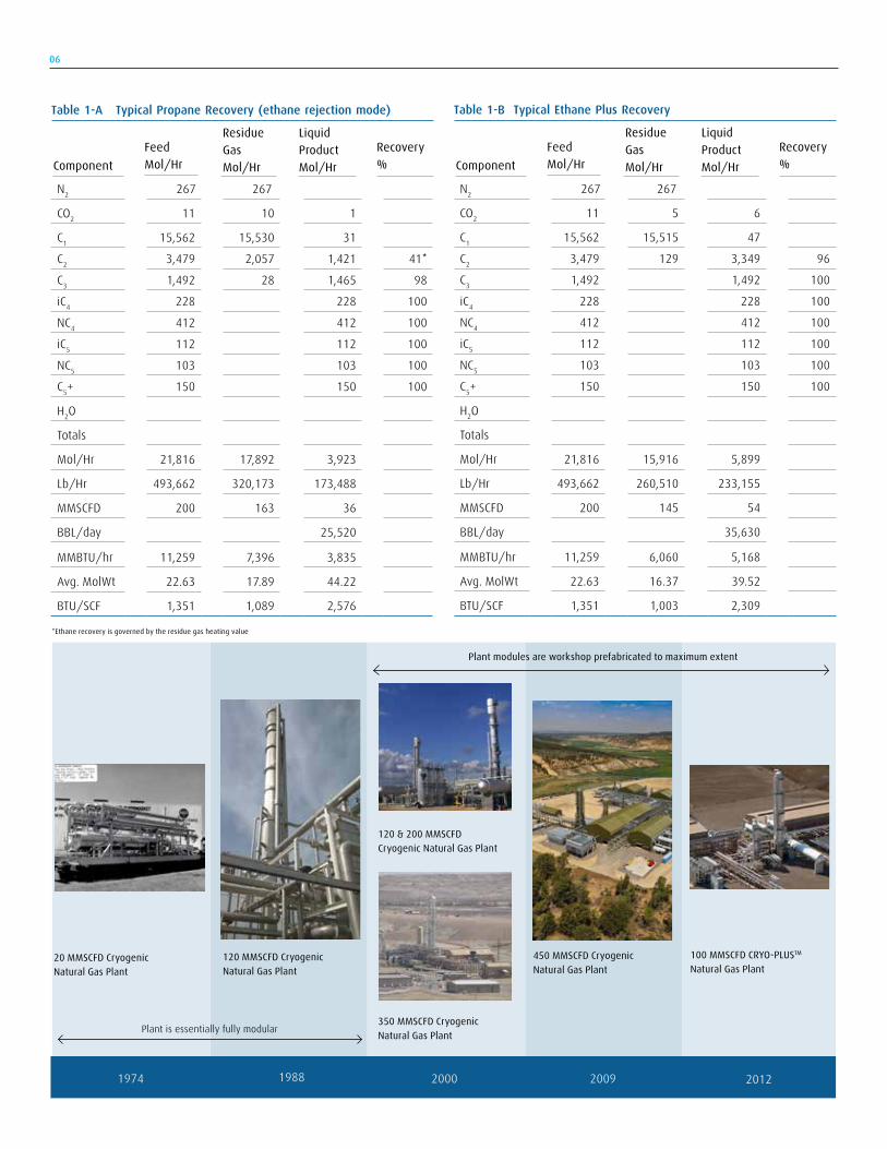
CRYO-PLUS™ Benefits The optimum C2 and C3 recoveries are a function of the relative values of the recovered components, the fuel gas, utilities, fit to available compression, and the required economic payout. CRYO-PLUS™ recovery for C2 is typically 96%, with essentially 100% recovery of C3 and heavier components when operated in ethane recovery mode. Corresponding recoveries for ethane rejection mode is 98% or greater for C3, and 100% of the heavier components. Typical CRYO-PLUS™ feed and product compositions are indicated in Table 1A and Table 1B for the two modes of operation. The material balances are for a nominal 200 MMSCFD feed gas from a shale gas well. For example, assuming a natural gas fuel value of $3.75/MMBTU, this gas as fuel has a value of approximately $1,013,325/Day. When operating in ethane rejection mode as shown in Table 1A, the CRYO-PLUS™ technology recovers approximately 25,520 BBL/Day of mixed C2+ liquids. If the average value of the C2+ liquids is $0.57/gallon, then the combined value of the C2+ liquids plus the residue gas as fuel is $1,276,317/Day.
This differential results in a gross margin between the two operations of over $92,000,000 per year. These simplified calculations assume that the plant can sell the higher BTU natural gas stream without any treatment. This is normally not possible due to pipeline requirements, but it may be possible to do minimum treatment and disposing the liquids. When disposing the liquids or flaring this high BTU gas, these already impressive economics improve dramatically. (Substitute your own product values and see your impact.) The recovered liquid stream’s composition is a reflection of the fuel gas streams that comprise the CRYO-PLUS™ feeds. Alterna-tively, the C2, C3 and C4’s can be split by fractionation and each can be fed to a separate process for further upgrading or simply sold as chemical feedstock.
The same economic calculations can be done for operation in ethane recovery mode as is shown in Table 1B. In this case, the CRYO-PLUS™ technology recovers approximately 35,630 BBL/Day of mixed C2+ liquids. Due to a higher ethane content, the average value of this mix may be lower so if $0.44/gallon is used instead, then the combined value of the C2+ liquids plus the residue gas as fuel is $1,210,029/Day. The differential this time results in a gross margin between the two operations of over $68,800,000 per year, which is still an attractive return.
A subtle, but very real additional benefit of CRYO-PLUS™ derives from the change in the fuel gas composition after removing the C3 and C4 components. The higher heating value of the C3 and C4’s results in a higher flame temperature within the furnace or boiler; this may result in higher NOx emissions. Removal of C3 and C4 components from the fuel gas therefore achieves a measurable reduction in NOx emissions. This incremental reduction may be enough to keep the end-user of the gas in compliance and avoid expensive NOx reduction modifications for the combustion processes.
05
06
1974 1988 2000 2009 2012
20 MMSCFD Cryogenic Natural Gas Plant
120 MMSCFD Cryogenic Natural Gas Plant
120 & 200 MMSCFD Cryogenic Natural Gas Plant
350 MMSCFD Cryogenic Natural Gas Plant
450 MMSCFD Cryogenic Natural Gas Plant
100 MMSCFD CRYO-PLUSTM
Natural Gas Plant
Plant is essentially fully modular
Plant modules are workshop prefabricated to maximum extent
*Ethane recovery is governed by the residue gas heating value
Table 1-A Typical Propane Recovery (ethane rejection mode)
N2 267 267
CO2 11 10 1
C1 15,562 15,530 31
C2 3,479 2,057 1,421 41*
C3 1,492 28 1,465 98
iC4 228 228 100
NC4 412 412 100
iC5 112 112 100
NC5 103 103 100
C5+ 150 150 100
H2O
Totals
Mol/Hr 21,816 17,892 3,923
Lb/Hr 493,662 320,173 173,488
MMSCFD 200 163 36
BBL/day 25,520
MMBTU/hr 11,259 7,396 3,835
Avg. MolWt 22.63 17.89 44.22
BTU/SCF 1,351 1,089 2,576
ComponentFeedMol/Hr
ResidueGasMol/Hr
LiquidProductMol/Hr
Recovery%
Table 1-B Typical Ethane Plus Recovery
N2 267 267
CO2 11 5 6
C1 15,562 15,515 47
C2 3,479 129 3,349 96
C3 1,492 1,492 100
iC4 228 228 100
NC4 412 412 100
iC5 112 112 100
NC5 103 103 100
C5+ 150 150 100
H2O
Totals
Mol/Hr 21,816 15,916 5,899
Lb/Hr 493,662 260,510 233,155
MMSCFD 200 145 54
BBL/day 35,630
MMBTU/hr 11,259 6,060 5,168
Avg. MolWt 22.63 16.37 39.52
BTU/SCF 1,351 1,003 2,309
ComponentFeedMol/Hr
ResidueGasMol/Hr
LiquidProductMol/Hr
Recovery%
07
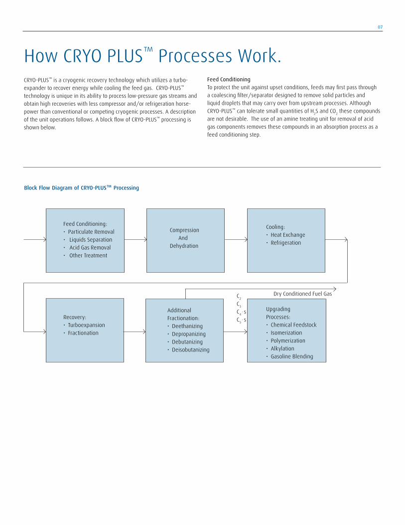
CRYO-PLUS™ is a cryogenic recovery technology which utilizes a turbo-expander to recover energy while cooling the feed gas. CRYO-PLUS™ technology is unique in its ability to process low-pressure gas streams and obtain high recoveries with less compressor and/or refrigeration horse-power than conventional or competing cryogenic processes. A description of the unit operations follows. A block flow of CRYO-PLUS™ processing is shown below.
Feed Conditioning To protect the unit against upset conditions, feeds may first pass through a coalescing filter/separator designed to remove solid particles and liquid droplets that may carry over from upstream processes. Although CRYO-PLUS™ can tolerate small quantities of H2S and CO2 these compounds are not desirable. The use of an amine treating unit for removal of acid gas components removes these compounds in an absorption process as a feed conditioning step.
Cooling: • Heat Exchange • Refrigeration
Additional Fractionation: • Deethanizing • Depropanizing • Debutanizing • Deisobutanizing
Compression And Dehydration
Recovery: • Turboexpansion • Fractionation
Block Flow Diagram of CRYO-PLUS™ Processing
Feed Conditioning: • Particulate Removal • Liquids Separation • Acid Gas Removal • Other Treatment
C2
C3
C4 , sC5 , s
Upgrading Processes: • Chemical Feedstock • Isomerization • Polymerization • Alkylation • Gasoline Blending
Dry Conditioned Fuel Gas
How CRYO PLUS™ Processes Work.
08
Liquid Product
Heavy ends fractionation columnLight
ends fractionation
column
ColdSeparator
Expander
C3
Inlet HeatExchange
Inlet Gas from Dehydration
ResidueGas
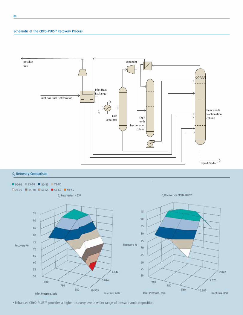
Schematic of the CRYO-PLUSTM Recovery Process

09
Feed Compression The next step is to compress the feed stream unless it is already at elevated pressures. An air cooler or cooling water, cools the gas downstream of the compressor to remove the heat of compression. (Heat of compression can also be used as a heat source for fractionation as permitted by the process heat balance and temperature driving force.)
Dehydration To avoid ice and hydrate formation in the cryogenic section of the process, the water content of the gas is reduced to an acceptable level through adsorption in molecular sieve desiccant beds. This is a batch process, where multiple (two or more) adsorption beds are used. One or more of the adsorption beds are being regenerated to restore their capacity while the other bed(s) are on-line and drying the feed gas. A recycle portion of the dry gas can be heated and used for regeneration of the beds to drive off the adsorbed water. Cooling of this stream condenses the removed water, before it recycles and combines with the feed gas. A portion of the residue gas may also be used for the regeneration on a once through basis. Downstream of the adsorption beds, the gas passes through a dust filter to remove any particulate carryover before subsequent processing.
Feed Cooling After dehydration, the feed gas flows into the cold section of the process, where cooling by exchange of heat with the residue gas and cold separator liquids takes place using a brazed aluminum plate-fin heat exchanger. Although not always a requirement, the gas may be further cooled using external refrigeration before it goes to the cryogenic portion of the process.
Cold Separation Following cooling, the feed gas is partially condensed and delivered to a vapor/liquid separator. The liquid then flows through the inlet exchanger to cool the feed gas before entering the deethanizer for fractionation. The vapor flows to the inlet of the expander/compressor. As the gas expands, it provides the work/energy for the compression. The expansion and removal of energy cools the gas further and causes additional condensa-tion. The expander discharges into the first tower of a two-stage fraction-ation process. The configuration and the combination of fractionation and heat transfer between these two columns is the proprietary, patented technology that gives CRYO-PLUS™ its advantages (higher recovery at reduced horsepower) over competing technologies.
A residue gas and a demethanized liquid product are produced from this two tower scheme. The residue gas is produced at pressures comparable to other competing technologies. Following exchange with the feed gas in the inlet cooling step, it arrives at the residue gas compression system as a dry, stable heating value fuel. The liquid product from the fraction-ation system is the recovered C2 or C3 liquid hydrocarbons. The liquid often undergoes additional processing, such as additional fractionation in downstream columns. For C3 recovery, the liquid stream is normally debutanized. The C3 and C4’s may then be fed to an alkylation process, or split with the C3 going to isomerization/polymerization and only the C4’s going to isomerization/alkylation feed. For C3 recovery, a depropanizer normally precedes the debutanizer.

10
Modular design and fabrication. Linde designs modules with an optimized layout accommodating maintenance access with minimized footprint and road transportation. In addition, a high degree of fabrication and testing of modules reduces on-site construction, and pre-commissioning activities.
A growing number of gas processing companies recognize the benefits of modular design and fabrication over conventional stick built design and construction. A modular approach provides, greater schedule predictability, and high quality. In addition, it minimizes risk and potential downtime associated with construction in an operating plant.
Schedule and Quality Adverse climate conditions can leave on-site activities at the mercy of the environment often jeopardizing schedule and quality. Module fabrication in the controlled environment of LENA’s facilities ensures the required quality, including cleanliness independent from outdoor conditions. On-site construction activities, including pre-commissioning, are minimized allowing for a more predictable schedule, and thereby the overall project cost and duration are reduced.
Downtime and Construction Risk High quality, prefabricated, and pressure tested modules minimize not only the overall construction activities on-site, but also the associated risk. Furthermore, in an operating plant, the installation and hook-up of these modules reduces downtime, potentially saving significant cost, and increasing work safety by minimizing time working alongside equipment containing hazardous high pressure material .
11
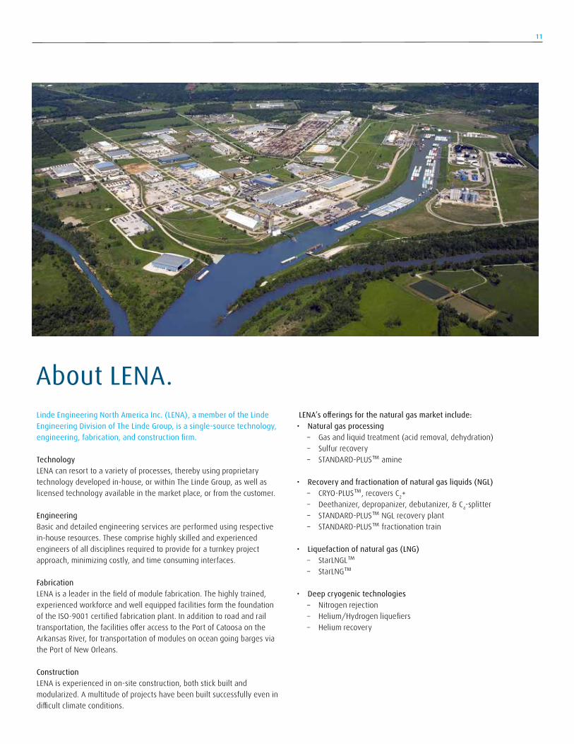
About LENA. Linde Engineering North America Inc. (LENA), a member of the Linde Engineering Division of The Linde Group, is a single-source technology, engineering, fabrication, and construction firm.
TechnologyLENA can resort to a variety of processes, thereby using proprietary technology developed in-house, or within The Linde Group, as well as licensed technology available in the market place, or from the customer.
EngineeringBasic and detailed engineering services are performed using respective in-house resources. These comprise highly skilled and experienced engineers of all disciplines required to provide for a turnkey project approach, minimizing costly, and time consuming interfaces.
FabricationLENA is a leader in the field of module fabrication. The highly trained, experienced workforce and well equipped facilities form the foundation of the ISO-9001 certified fabrication plant. In addition to road and rail transportation, the facilities offer access to the Port of Catoosa on the Arkansas River, for transportation of modules on ocean going barges via the Port of New Orleans.
ConstructionLENA is experienced in on-site construction, both stick built and modularized. A multitude of projects have been built successfully even in difficult climate conditions.
LENA’s offerings for the natural gas market include: • Natural gas processing – Gas and liquid treatment (acid removal, dehydration) – Sulfur recovery – STANDARD-PLUS™ amine
• Recovery and fractionation of natural gas liquids (NGL) – CRYO-PLUS™, recovers C2+ – Deethanizer, depropanizer, debutanizer, & C4-splitter – STANDARD-PLUS™ NGL recovery plant – STANDARD-PLUS™ fractionation train • Liquefaction of natural gas (LNG) – StarLNGL™ – StarLNG™
• Deep cryogenic technologies – Nitrogen rejection – Helium/Hydrogen liquefiers – Helium recovery

Linde Engineering North America Inc.6100 South Yale Avenue, Suite 1200, Tulsa, Oklahoma 74136 USAPhone +1.918.477.1200, Fax +1.918.477.1100, [email protected], www.leamericas.com
Engineering excellence – every step of the way.
Get in touch – find the best solution.
Linde Engineering North America Inc., a member of the Linde Engineering Division of the Linde Group, is a leading player in the international plant engineering business, covering every step in the design, project management, and construction of turnkey industrial plants. Drawing on our proven process know-how, we set the standards for innovation, flexibility with ground-breaking concepts and a dedication to engineering excellence.
The success of our customers and partners around the globe is of primary importance. With a clear focus on efficiency, sustainability and growth we develop solutions for projects of all sizes and degrees of complexity. We have already delivered more than 4,000 plants worldwide and always aim to find the best technical and economic solution for our customers.
The range of products comprises: → Petrochemical plants → LNG and natural gas processing plants → Air separation plants → Synthesis gas plants → Hydrogen plants → Gas processing plants → Adsorption plants → Cryogenic plants → Biotechnological plants → Furnaces for petrochemical plants and refineries
Linde and its subsidiaries manufacture: → Packaged units, cold boxes → Coil wound heat exchangers → Plate fin heat exchangers → Cryogenic standard tanks → Air heated vaporizers → Spiral-welded aluminum pipes → Cryogenic turboexpander/compressors → Cryogenic pumps