NATSPEC BIM Scheduling guidelines€¦ · Tony Avsec AIB David Eynon AMCA ... repository for...
41
Prepared by NATSPEC www.natspec.com.au PROJECTreport December 2010 NATSPEC BIM Scheduling guidelines Standardised Australian Practice for the Exchange of Digital Building Information Part A of this report sets out working principles for allocating properties to objects in Building Information Models (BIM) for scheduling purposes. The aim of these principles is to facilitate a consistent approach to scheduling and thereby improve information exchange in the construction industry. Part B outlines general concepts associated with schedules that form the basis of the working principles set out in Part A.
Transcript of NATSPEC BIM Scheduling guidelines€¦ · Tony Avsec AIB David Eynon AMCA ... repository for...

Prepared by
NATSPEC www.natspec.com.au
PROJECTreport
December 2010
NATSPEC BIM Scheduling guidelines Standardised Australian Practice for the Exchange of Digital Building Information
Part A of this report sets out working principles for allocating properties to objects in Building Information Models (BIM) for scheduling purposes. The aim of these principles is to facilitate a consistent approach to scheduling and thereby improve information exchange in the construction industry. Part B outlines general concepts associated with schedules that form the basis of the working principles set out in Part A.

NATSPEC Project Report December 2010
ACKNOWLEDGEMENTS
ACKNOWLEDGEMENTS
NATSPEC would like to thank the following individuals and organisations for their contribution to the project – it would not have been possible without them:
Lachlan McEwen DesignInc Project Chairman
Neil Greenstreet NATSPEC Project Manager
Tony Avsec AIB
David Eynon AMCA
Sumit Oberoi AMCA
Antony McPhee Antony McPhee Architects
Michael Carlotto Arkhefield
Andrew Maher ARUP
Fergus Dunn Bentley Systems
Gary Young BNgroup
Peter Clarke BVN
Dominik Holzer BVN
Royce Lee BVN
Bilal Succar ChangeAgents AEC
Russell Obst Conrad Gargett
John Mitchell CQR
Ceilidh Higgins GHD
David Pearce GHD
Tony Krepler Graphisoft
Paul Pearson KABA
Ross Daddo Lend Lease design
Richard Choy NATSPEC
Robin Drogemuller SBE-NRC
Laurent Deleu Simpson Kotzman
Dermot Small Simpson Kotzman
Colin Blair Standards Australia
Chris Linning Sydney Opera House
Scott Beazley TAFE
Cornelis (Kees) Wegman Wegman Architects
Gianni Zandel Woodhead
Fergus Hohnen Woods Bagot
David Marchant Woods Bagot
NATSPEC BIM Scheduling guidelines © i December 2010

NATSPEC Project Report December 2010
PREAMBLE
PREAMBLE
Earlier NATSPEC BIM-related activities
In 2008 NATSPEC hosted an informal discussion group in Melbourne on classification systems and their relationship to BIM with representatives from architectural and engineering practices. The purpose was to assess the current state of development in this area and to discuss likely trends and ways of responding to them. This led to the publication of the NATSPEC TECHreport Information classification systems and the Australian construction industry and NATSPEC concluding that the NATSPEC classification system sat within the Work results and Work processes Tables of ISO 12006:2001 – Building construction – Organisation of information about construction works – Part 2; Framework for classification of information.
Project background
Early in 2010 a number of NATSPEC subscribers expressed interest in developing some guidelines which would facilitate the exchange of information associated with BIM in response to a lack of a uniform approach to this issue by creators of digital models.
An online survey was conducted to gather opinions about the type of guidelines required and identify priorities. The survey results guided the formulation of an agenda for a meeting held in Melbourne in June, 2010. In the interests of producing a tangible outcome within a reasonable period, the attendees agreed to focus on a specific topic. After discussing a number of options, it was agreed to make schedules the subject of the project.
Goal
The project goal adopted by the meeting was to recommend a consistent, systematic approach to allocating properties to Building Information Model (BIM) objects to facilitate the generation of useful schedules.
This entailed standardising:
• Semantics: Formalising the meaning of terms used in schedules to eliminate ambiguity; e.g. making it clear if ‘width’ in a door schedule refers the width of the door leaf, the door leaf with frame, or the wall opening.
• Syntax: Formalising which characteristics associated with scheduled items should be included in the schedule, and their ordering.
Schedules
Schedules are probably one of the most common non-graphic outputs generated from BIM. They are used for presenting the information content of models in a concise and familiar format that can be understood by most people, even those with no working knowledge of BIM. A consistent approach to their creation and use increases their effectiveness as a means of information exchange.
Project values
- Emphasis: The project focussed on the ‘i’ (information) in BIM, and less on 3D modelling aspects. It was concerned with broad organisational principles and procedures rather than detailed instructions for the use of modelling applications. The focus was on guidelines and standards beneficial to the construction industry as a whole.
- Non proprietary: The intention was to produce results that could be applied as widely as possible, regardless of the modelling software being used.
- Generic terminology: With an open standard, non proprietary result in mind, an attempt was made to formulate generic terms to describe otherwise proprietary application features, commands, procedures or outputs.
- Inclusive: Participation by NATSPEC subscribers and non-subscribers was invited and welcomed alike.
- Collaborative approach: As standards rely on broad acceptance by their user group for their adoption and use, a collaborative approach to their development was encouraged. The project relied on voluntary efforts and a willingness by participants to provide relevant information. The commercial confidence of any material not publicly posted by its author/s was protected, and participants' contributions' acknowledged.
- Outcome focussed: The thrust of the project was to consciously direct dialogue towards an identifiable outcome within a finite timeframe.
Working method
The intention of the project was not to create a comprehensive set of schedules typically associated with construction documentation but to formulate working principles that could be applied by anyone for a variety of requirements. The scope of study was also confined to scheduling for design and documentation purposes, and did not extend to their use for facility management purposes.
Initially, a large number of schedules for a variety of items were submitted for study to NATSPEC by architects and engineers. Principles around the two broad areas identified in the project goals (standardising schedule semantics
NATSPEC BIM Scheduling guidelines © ii December 2010
NATSPEC Project report December 2010
PREAMBLE
and syntax) were formulated and described in a number of working documents which were posted on the project website for comment. Proposals for standardising practices were deliberately kept broad initially in order to establish consensus, with the plan to make them progressively more specific over the project period.
The working principles and guidelines identified were then applied to a small number of schedules to test their robustness.
Implementation
A website bim.natspec.org was launched on 30th July, 2010 to provide information about the project, as a repository for working documents and to host a forum for the discussion of issues. Resources for participants such as Background papers, links to relevant websites and a Glossary were also provided on the website. Those at the Melbourne meeting and others interested were invited to comment on the working documents, join forum discussions or participate in the project by a variety of means.
All documents cited and links provided below are from the project website.
Aspects of schedules examined
Semantics
Consistent, unambiguous terminology for describing items being scheduled and their properties is essential for accurate, error-free exchange of information between models and their users. The literal way in which computer applications handle text necessitates much greater precision than traditional written communications where the interpretative abilities of the human correspondents compensate for ambiguities. A number of aspects of this topic were examined in the following working documents on the website:
• Schedule semantics recommends sources of terminology and definitions and offers guidance about the precedence each should take.
• Schedule heading glossaries illustrates the application of the recommendations made in Schedule semantics using a door and door hardware schedule as an example. As schedule headings represent the properties of the items being scheduled, the document is essentially about selecting and defining object properties. The concept of compiling a parent list of properties for an object type, and selecting subsets of them for different purposes, is introduced. Defining what is meant by terms used to describe the dimensions of objects is identified as a crucial task.
• Describing the dimensions of BIM objects proposes a set of conventions for written descriptions of an object's dimensions that can be applied in a digital modelling environment. Conventions are necessary to make the orientation of dimensions clear when they are not accompanied by a reference image, i.e. in text-only documents. Adoption of the proposed conventions would allow dimensions from different sources to be scheduled in a consistent way.
Syntax
Arranging information in a consistent manner assists its retrieval when required. Predictable patterns and familiar formats also facilitate communications between parties. A number of aspects of this topic were examined in the following working documents:
• Schedule syntax suggests an order in which properties should be displayed in a schedule, based on some principles outlined in a Background paper Information ordering.
• Schedule heading glossaries illustrates the application of Schedule syntax using a door and door hardware schedule as an example. The properties in the schedule are listed in the order suggested in Schedule syntax.
Protocol
Multi-stage scheduling illustrates the principles outlined in a Background paper Using schedules for data exchange. It examines how their information content and format changes to suit the needs of different users at various stages of a project. A series of schedules for two types of items - fans and door hardware - are used to illustrate this process.
Response
Attendees of the Melbourne meeting and others were notified of the launch of the website and when new content was added. This included a number of people who had responded to an earlier online survey about BIM conducted by buildingSMART Australia and had indicated their interest in participating in the scheduling project.
As at 1st November, 2010 there were:
NATSPEC BIM Scheduling guidelines © iii December 2010
NATSPEC Project report December 2010
PREAMBLE
• Over 1,000 hits on website articles with a greater total number of hits on the website as a whole.
• Over 50 interested parties registered with the BIM Forum.
• Over 400 viewings of forum posts and 15 replies to the 3 topics listed.
In addition, a small number of people offered comments by email and telephone. The Australian Mechanical Contractor's Association (AMCA) showed particular interest in the Multi-stage scheduling paper and then initiated their own project on a similar subject - standards for the exchange of information on mechanical equipment objects in digital models at different stages of projects. AMCA continues to develop some of the concepts covered by the project.
No one challenged the approaches proposed in the website articles, and a number of individuals expressed their support for them. Most respondents were seeking clarification of the proposals and the project's scope, or raising other issues for consideration.
This project report will be distributed more widely throughout Australia and internationally to seek more feedback.
Conclusion
Papers on the website examined issues of standardised practice for the exchange of digital building information with regard to schedules. Examples of the application of working principles formulated in the papers demonstrated their viability.
The way forward
The schedules included in NATSPEC specifications will be reviewed to determine where they might benefit from the application of working principles formulated during this project. This would also provide an opportunity to elicit additional feedback from those who expressed an interest in the subject.
Options for implementing the practice standards for information exchange identified during the project include:
• Placing excel files of the amended NATSPEC schedules on the BIM website for download.
• Developing a glossary of abbreviations used in schedules to improve consistency of use.
• Developing a system of keynoting codes based on the NATSPEC classification system to facilitate the coordination of digital models, drawings, schedules and specifications
For updates on these initiatives, visit bim.natspec.org.
NATSPEC BIM Scheduling guidelines © iv December 2010
NATSPEC Project Report December 2010
CONTENTS
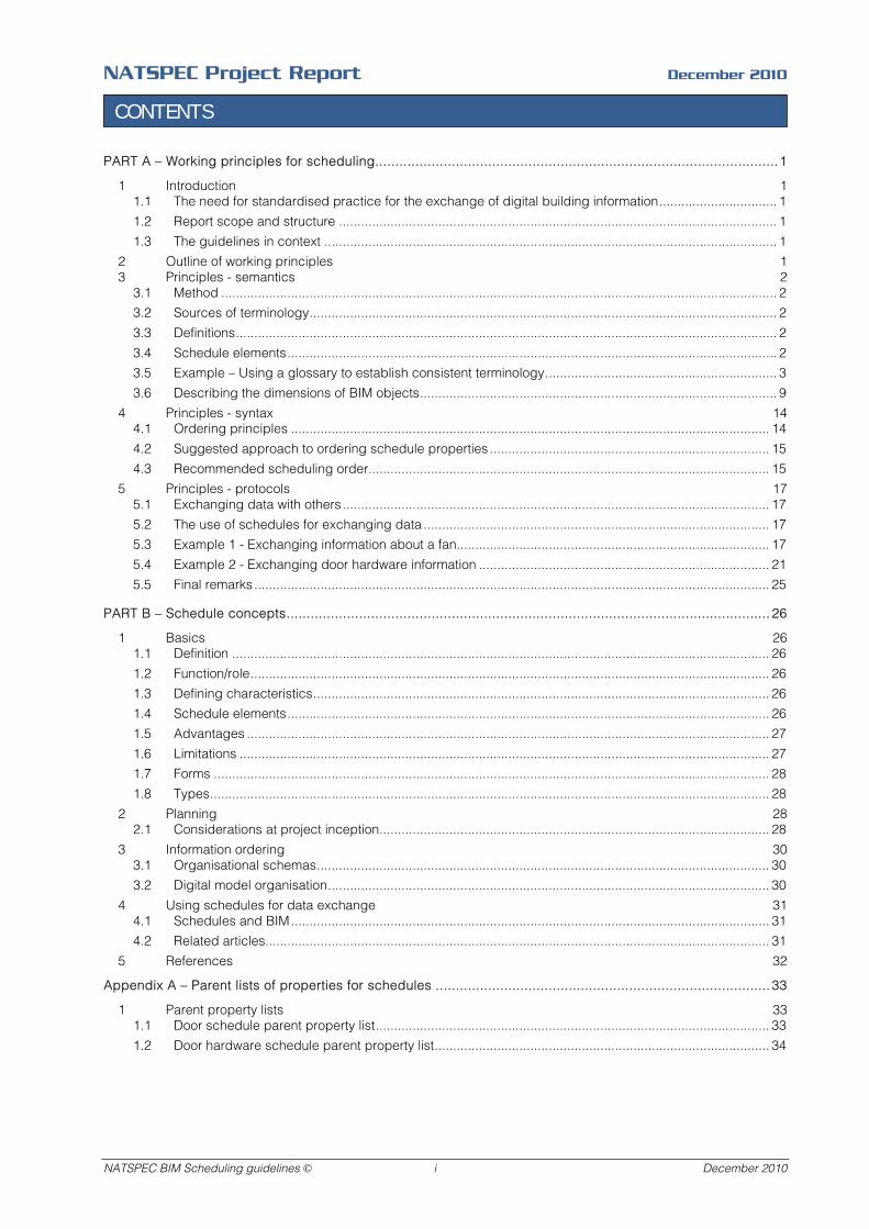
PART A – Working principles for scheduling....................................................................................................1
1 Introduction 1 1.1 The need for standardised practice for the exchange of digital building information................................ 1 1.2 Report scope and structure ....................................................................................................................... 1 1.3 The guidelines in context ........................................................................................................................... 1
2 Outline of working principles 1 3 Principles - semantics 2
3.1 Method ....................................................................................................................................................... 2 3.2 Sources of terminology............................................................................................................................... 2 3.3 Definitions................................................................................................................................................... 2 3.4 Schedule elements..................................................................................................................................... 2 3.5 Example – Using a glossary to establish consistent terminology............................................................... 3 3.6 Describing the dimensions of BIM objects................................................................................................. 9
4 Principles - syntax 14 4.1 Ordering principles .................................................................................................................................. 14 4.2 Suggested approach to ordering schedule properties ............................................................................ 15 4.3 Recommended scheduling order............................................................................................................. 15
5 Principles - protocols 17 5.1 Exchanging data with others.................................................................................................................... 17 5.2 The use of schedules for exchanging data .............................................................................................. 17 5.3 Example 1 - Exchanging information about a fan..................................................................................... 17 5.4 Example 2 - Exchanging door hardware information ............................................................................... 21 5.5 Final remarks............................................................................................................................................ 25
PART B – Schedule concepts........................................................................................................................ 26
1 Basics 26 1.1 Definition .................................................................................................................................................. 26 1.2 Function/role............................................................................................................................................. 26 1.3 Defining characteristics............................................................................................................................ 26 1.4 Schedule elements................................................................................................................................... 26 1.5 Advantages .............................................................................................................................................. 27 1.6 Limitations ................................................................................................................................................ 27 1.7 Forms ....................................................................................................................................................... 28 1.8 Types........................................................................................................................................................ 28
2 Planning 28 2.1 Considerations at project inception.......................................................................................................... 28
3 Information ordering 30 3.1 Organisational schemas........................................................................................................................... 30 3.2 Digital model organisation........................................................................................................................ 30
4 Using schedules for data exchange 31 4.1 Schedules and BIM.................................................................................................................................. 31 4.2 Related articles......................................................................................................................................... 31
5 References 32
Appendix A – Parent lists of properties for schedules ................................................................................... 33
1 Parent property lists 33 1.1 Door schedule parent property list........................................................................................................... 33 1.2 Door hardware schedule parent property list........................................................................................... 34
NATSPEC BIM Scheduling guidelines © i December 2010

NATSPEC Project Report December 2010
PART A – WORKING PRINCIPLES FOR SCHEDULING
PART A – WORKING PRINCIPLES FOR SCHEDULING
1 INTRODUCTION
1.1 The need for standardised practice for the exchange of digital building information
Working with Building Information Models is very different to working with traditional paper-based and 2D CAD based systems – they rely on highly structured data and protocols. As BIM is increasingly used for collaborative working methods (Integrated Practice) a much more formalised and standardised approach to exchanging data is demanded.
Schedules, the subject of this report, were selected as an area for standardising practice by a group of NATSPEC subscribers and construction industry representatives. Schedules represent the most commonly used method for representing and exchanging the (non graphical) information content of digital models.
1.2 Report scope and structure
This report is based on excerpts from the NATSPEC BIM Scheduling website (http://bim.natspec.org). It documents principles that can be applied when allocating properties to BIM to facilitate the generation of effective schedules. The principles outlined are not exhaustive – the domain of building information is vast and the report represents but a sample of some parts of that domain.
The report is divided into two main parts:
• Part A summarises the working principles developed during the NATSPEC BIM Scheduling project. Most of the material is derived from the Working documents found on the website. Examples or demonstrations of how some principles can be applied in practice are also provided.
• Part B contains some of the theory that forms the basis of the principles found in Part A. Most of the material is derived from the Background papers found on the website. Cross-references that link related content in each part are provided throughout the document.
1.3 The guidelines in context
The guidelines are part of the development of industry-wide formal standards for the exchange of digital building information. This development process could be characterised by the following stages:
1. Analysis of existing practices.
2. Formulation of the abstract principles (theory) underlying existing good practice.
3. Formulation of working principles.
4. Drafting of formal standards of practice.
The initial stages of the NATSPEC BIM Scheduling project included the type of analysis described in Item 1. A large number of schedules were submitted by practitioners for study by NATSPEC.
Part B of the report outlines the theory described in Item 2.
Part A of the report documents the working principles described in Item 3. They represent the formalisation of principles that many people use regularly and effectively without ever enunciating them.
The drafting of formal standards is assisted by the contents of Part A. The working principles found in Part A can be viewed as precursors to detailed formal standards of the type one might expect to find in a documentation manual.
2 OUTLINE OF WORKING PRINCIPLES
The working principles set out in this part of the report have been subdivided into three facets:
• Semantics “Relating to meaning in language and the connotations of words”. Formalising the meaning of terms used in schedules is necessary to eliminate ambiguity and potential errors, e.g. making it clear if ‘width’ in a door schedule refers to the width of the door leaf, the door leaf with frame, or the wall opening.
• Syntax “The grammatical arrangement of words in speech or writing to show their connection and relation.” Used more broadly in this document to include rules or principles applied to the arrangement of all schedule content. Formalising the properties of scheduled items and how they are ordered assists the retrieval of information.
• Protocol: “A set of standardised procedures for transmitting or storing data, especially those used in regulating data transmission between computers or peripherals”. Formalising the data content of a digital model – as expressed in schedules – and the processes for exchanging it between members of the project team is necessary for the smooth running of the project and to minimise duplication of effort
NATSPEC BIM Scheduling guidelines © 1 December 2010

NATSPEC Project Report December 2010
PART A – WORKING PRINCIPLES FOR SCHEDULING
and reduce errors. This entails deciding who will be responsible for providing the required information, in what form and level of detail, and who will be responsible for acting on it at each stage of the project.
3 PRINCIPLES - SEMANTICS
3.1 Method
The method for formalising the use and meaning of terms used in schedules can be summarised as follows:
- Select appropriate sources of terminology
- Where similar terms exist for the same item or concept, select the clearest, least ambiguous one.
- Where different definitions are found for the same term, select the one from the most authoritative source.
- Where a definition for a term does not exist, carefully draft one. Seek consensus on the definition where possible before finalising it.
- Examine selected terms and definitions for potential ambiguities, and adjust as necessary to minimise them.
- Document and disseminate glossaries of defined terms to users.
3.2 Sources of terminology
When formalising the meaning of terms used in a schedule give preference to defined terms from sources with regulatory and legal standing. It is important that terms selected do not contradict or blur the meaning of terms used in documents like the Building Code of Australia (BCA) or standards cited in the specification.
If choosing between alternative definitions of a term, give preference to the listed sources in the following order:
1. BCA.
2. Australian Standards and Handbooks.
3. Appropriate international and national standards.
4. Terminology, abbreviations and codes used by major client groups.
5. Publications by professional and government organisations.
6. Publications by trade organisations.
7. Publications by manufacturers’ organisations.
8. Product technical literature.
9. Established and accepted industry usage.
Use terms derived from well established, industry endorsed publications that have been peer-reviewed. Many make a point of defining the terms applicable to their subject matter, so they are a good source of terminology.
Only use proprietary terms or brand names when specifically nominating a proprietary item to be used.
3.3 Definitions
1. Where necessary, provide definitions adjacent to the schedule to eliminate ambiguity, e.g. define ‘width’ so that it is clear whether it refers to a nominal width, an overall width or opening width.
2. Identify the source of definitions. If there are a lot of definitions, or they are of a complex or specialised nature, it may be more appropriate to omit the definitions and refer directly to the source document, e.g. ‘Refer to AS 4145.1 for definitions of terms used in this schedule.’
3. Add qualifying adjectives or pronouns to terms, e.g. panel width, opening width if it will reduce the risk of misinterpretation.
3.4 Schedule elements
1. Title: Follow the naming conventions adopted for the class of objects scheduled.
2. Identifiers: Keep identification codes short – one, two or three letters plus the minimum number of digits that will accommodate the number of items likely to be scheduled. (one digit – 9 items, two digits – 99 items, and so on).
3. Make identification codes as self-evident and intuitive as possible to aid recognition.
4. Provide a legend on any document in which identification codes appear.
NATSPEC BIM Scheduling guidelines © 2 December 2010

NATSPEC Project Report December 2010
PART A – WORKING PRINCIPLES FOR SCHEDULING
3.5 Example – Using a glossary to establish consistent terminology
Glossary of terms for properties
Table 1 on the following pages is an example of the sort of document that can be used to record the names and definitions of headings (i.e. properties) to be included in a schedule – in this instance a door schedule. It is an example of one of many that could be created for this purpose. In addition to acting as a glossary, it also prescribes the format of values associated with each property. The list of properties is not exhaustive – they have been extracted from a parent list of door and door hardware properties. See Appendix A for the parent lists. The subset of properties chosen from the parent list would vary with each project. For example, a door schedule for a house will require a simpler set of properties than one for a hospital.
Document purpose
This sort of document is intended to be used as a template for anyone creating or using model content - in this instance, doors. As a common reference it would facilitate a consistent approach by all modellers.
Some of its content might appear self-evident and unremarkable. 'Frame material', for example, would not appear to require a definition. The most significant thing about it is the principles it embodies, which are:
- Derivation of terms and definitions from established, credible sources such as the BCA and Australian Standards. This approach does not have to be applied rigidly - there can be instances where alternatives are more appropriate. A table like this is the ideal place to document any divergences and explain the reasons, if required.
- Identification of the preferred term to be adopted from among a number of options. In everyday conversation the terms 'door', 'door panel' and 'door leaf' might all be used interchangeably and still be understood to be referring to the same thing, but the use of terms in a BIM context demands less ambiguity.
- Definition of how an item is to be measured for the purpose of describing its size in a consistent manner. Again, 'door width' could easily be interpreted as referring to the width of the door leaf, the clear door opening width of the door frame, the overall dimension of the door frame, or the rough opening width. The document acts to say: "of all these alternatives, we will adopt 'leaf width' as the primary measure of door width." This does not preclude the use of other measures such as rough opening width, if required - they just need to be defined clearly as well and used consistently.
- A statement of the required values for properties and/or the provision of examples of acceptable value formats. Even if the meaning of a property description is likely to be readily understood without much explanation, the potential always exists that different people will enter values for them in a variety of formats or units.
- The order properties are listed. That is: (1) Identification/Doorset (properties of the assembly as a whole), then (2) Door leaf (primary component), then (3) Door frame (secondary component), then (4) Door hardware (ancillary components).
- Definition of the scope and level of detail of information that is expected. The table can be used to clarify, for example, whether the information required for a particular schedule entry is either 'yes' (present) or 'no' (not present), a brief description of type, a product code, or a detailed description of type, material, finish, colour, etc.
Sources of terms and definitions used in Table 1
AS 4145.1-2008 Locksets and hardware for doors and windows – Part 1: Glossary of terms and rating system.
Building Code of Australia.
SAA HB 50-2004 Glossary of Building Terms.
NATSPEC BIM Scheduling guidelines © 3 December 2010
NATSPEC Project Report December 2010
PART A – WORKING PRINCIPLES FOR SCHEDULING
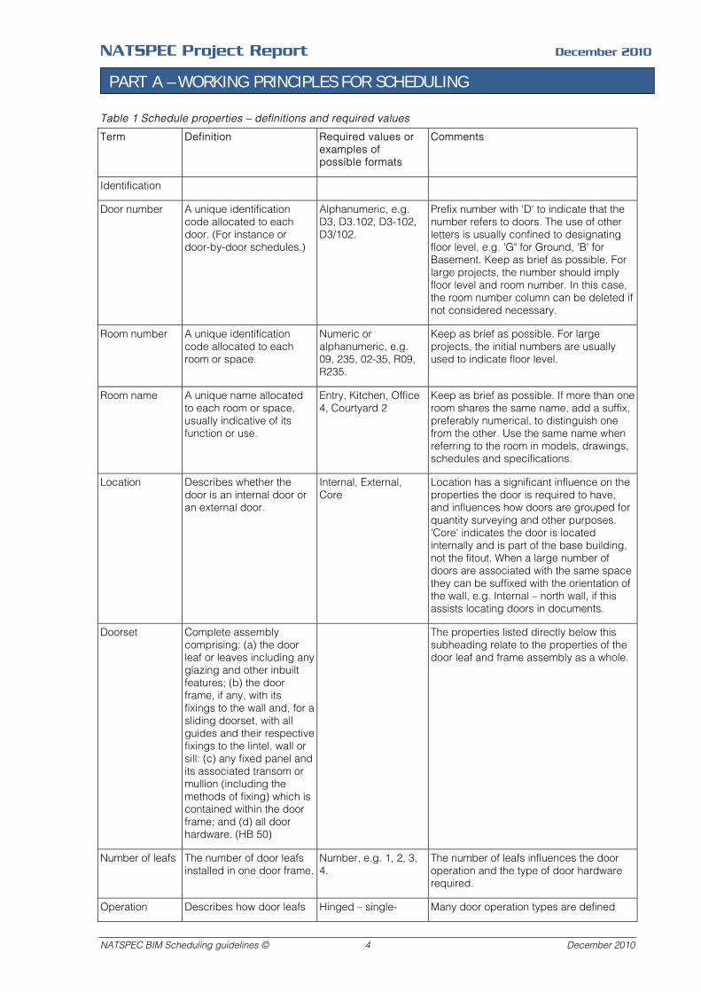
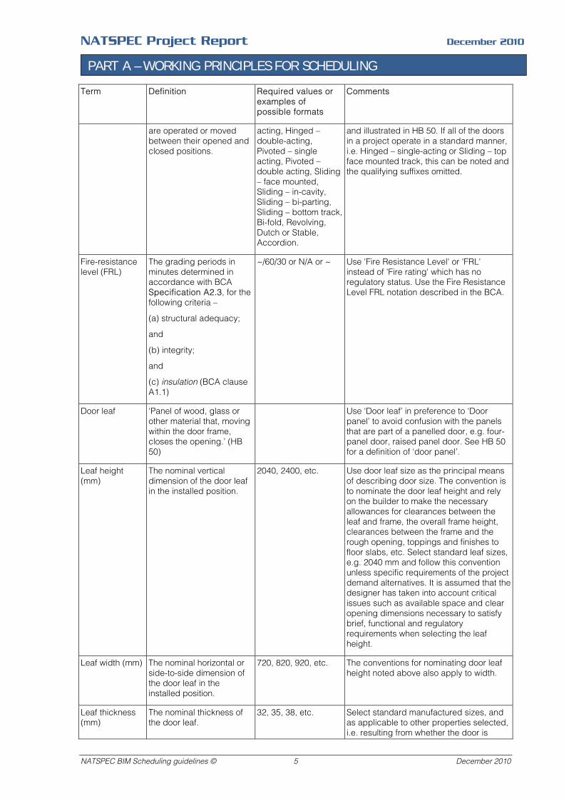
Table 1 Schedule properties – definitions and required values
Term
Definition
Required values or examples of possible formats
Comments
Identification
Door number A unique identification code allocated to each door. (For instance or door-by-door schedules.)
Alphanumeric, e.g. D3, D3.102, D3-102, D3/102.
Prefix number with 'D' to indicate that the number refers to doors. The use of other letters is usually confined to designating floor level, e.g. 'G" for Ground, 'B' for Basement. Keep as brief as possible. For large projects, the number should imply floor level and room number. In this case, the room number column can be deleted if not considered necessary.
Room number A unique identification code allocated to each room or space.
Numeric or alphanumeric, e.g. 09, 235, 02-35, R09, R235.
Keep as brief as possible. For large projects, the initial numbers are usually used to indicate floor level.
Room name A unique name allocated to each room or space, usually indicative of its function or use.
Entry, Kitchen, Office 4, Courtyard 2
Keep as brief as possible. If more than one room shares the same name, add a suffix, preferably numerical, to distinguish one from the other. Use the same name when referring to the room in models, drawings, schedules and specifications.
Location Describes whether the door is an internal door or an external door.
Internal, External, Core
Location has a significant influence on the properties the door is required to have, and influences how doors are grouped for quantity surveying and other purposes. 'Core' indicates the door is located internally and is part of the base building, not the fitout. When a large number of doors are associated with the same space they can be suffixed with the orientation of the wall, e.g. Internal – north wall, if this assists locating doors in documents.
Doorset Complete assembly comprising: (a) the door leaf or leaves including any glazing and other inbuilt features; (b) the door frame, if any, with its fixings to the wall and, for a sliding doorset, with all guides and their respective fixings to the lintel, wall or sill: (c) any fixed panel and its associated transom or mullion (including the methods of fixing) which is contained within the door frame; and (d) all door hardware. (HB 50)
The properties listed directly below this subheading relate to the properties of the door leaf and frame assembly as a whole.
Number of leafs The number of door leafs installed in one door frame.
Number, e.g. 1, 2, 3, 4.
The number of leafs influences the door operation and the type of door hardware required.
Operation Describes how door leafs Hinged – single- Many door operation types are defined
NATSPEC BIM Scheduling guidelines © 4 December 2010
NATSPEC Project Report December 2010
PART A – WORKING PRINCIPLES FOR SCHEDULING
Term
Definition
Required values or examples of possible formats
Comments
are operated or moved between their opened and closed positions.
acting, Hinged – double-acting, Pivoted – single acting, Pivoted – double acting, Sliding – face mounted, Sliding – in-cavity, Sliding – bi-parting, Sliding – bottom track, Bi-fold, Revolving, Dutch or Stable, Accordion.
and illustrated in HB 50. If all of the doors in a project operate in a standard manner, i.e. Hinged – single-acting or Sliding – top face mounted track, this can be noted and the qualifying suffixes omitted.
Fire-resistance level (FRL)
The grading periods in minutes determined in accordance with BCA Specification A2.3, for the following criteria –
(a) structural adequacy;
and
(b) integrity;
and
(c) insulation (BCA clause A1.1)
~/60/30 or N/A or ~ Use 'Fire Resistance Level' or 'FRL' instead of 'Fire rating' which has no regulatory status. Use the Fire Resistance Level FRL notation described in the BCA.
Door leaf ‘Panel of wood, glass or other material that, moving within the door frame, closes the opening.’ (HB 50)
Use ‘Door leaf’ in preference to ‘Door panel’ to avoid confusion with the panels that are part of a panelled door, e.g. four-panel door, raised panel door. See HB 50 for a definition of ‘door panel’.
Leaf height (mm)
The nominal vertical dimension of the door leaf in the installed position.
2040, 2400, etc. Use door leaf size as the principal means of describing door size. The convention is to nominate the door leaf height and rely on the builder to make the necessary allowances for clearances between the leaf and frame, the overall frame height, clearances between the frame and the rough opening, toppings and finishes to floor slabs, etc. Select standard leaf sizes, e.g. 2040 mm and follow this convention unless specific requirements of the project demand alternatives. It is assumed that the designer has taken into account critical issues such as available space and clear opening dimensions necessary to satisfy brief, functional and regulatory requirements when selecting the leaf height.
Leaf width (mm) The nominal horizontal or side-to-side dimension of the door leaf in the installed position.
720, 820, 920, etc. The conventions for nominating door leaf height noted above also apply to width.
Leaf thickness (mm)
The nominal thickness of the door leaf.
32, 35, 38, etc. Select standard manufactured sizes, and as applicable to other properties selected, i.e. resulting from whether the door is
NATSPEC BIM Scheduling guidelines © 5 December 2010
NATSPEC Project Report December 2010
PART A – WORKING PRINCIPLES FOR SCHEDULING
Term
Definition
Required values or examples of possible formats
Comments
internal, external, a fire door, etc.
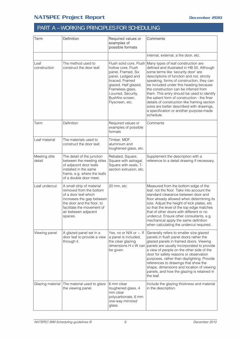
Leaf construction
The method used to construct the door leaf.
Flush solid core, Flush hollow core, Flush panel, Framed, Six panel, Ledged and braced, Framed glazed, Half glazed, Frameless glass, Louvred, Security, Bushfire screen, Flyscreen, etc.
Many types of leaf construction are defined and illustrated in HB 50. Although some terms like 'security door' are descriptions of function and not, strictly speaking, forms of construction, they can be included under this heading because the construction can be inferred from them. This entry should be used to identify the salient form of construction - the finer details of construction like framing section sizes are better described with drawings, a specification or another purpose-made schedule.
Term
Definition
Required values or examples of possible formats
Comments
Leaf material
The materials used to construct the door leaf.
Timber, MDF, aluminium and toughened glass, etc.
Meeting stile detail
The detail of the junction between the meeting stiles of adjacent door leafs installed in the same frame, e.g. where the leafs of a double door meet.
Rebated, Square, Square with astragal, Square with seals, T-section extrusion, etc.
Supplement the description with a reference to a detail drawing if necessary.
Leaf undercut A small strip of material removed from the bottom of a door leaf which increases the gap between the door and the floor, to facilitate the movement of air between adjacent spaces.
20 mm, etc Measured from the bottom edge of the leaf, not the floor. Take into account the standard clearance between door and floor already allowed when determining its size. Adjust the height of kick plates, etc so that the level of the top edge matches that of other doors with different or no undercut. Ensure other consultants, e.g. mechanical apply the same definition when calculating the undercut required.
Viewing panel A glazed panel set in a door leaf to provide a view through it.
Yes, no or N/A or ~. If a panel is included, the clear glazing dimensions H x W can be given.
Generally refers to smaller size glazed panels in flush panel doors rather the glazed panels in framed doors. Viewing panels are usually incorporated to provide a view of people on the other side of the door for safety reasons or observation purposes, rather than daylighting. Provide references to drawings that show the shape, dimensions and location of viewing panels, and how the glazing is retained in the leaf.
Glazing material The material used to glaze the viewing panel.
6 mm clear toughened glass, 4 mm clear polycarbonate, 6 mm one-way mirrored glass.
Include the glazing thickness and material in the description.
NATSPEC BIM Scheduling guidelines © 6 December 2010

NATSPEC Project Report December 2010
PART A – WORKING PRINCIPLES FOR SCHEDULING
Term
Definition
Required values or examples of possible formats
Comments
Ventilation grille A grille incorporated into the door leaf to allow the passage of air through it.
Yes, no or N/A or ~. If a grille is included, the dimensions H x W internal clear opening size of the frame can be given.
If a number of types are included in the schedule, differentiate them by their material and/or form, e.g. aluminium louvred. Provide references to drawings that show the shape, dimensions and location of grilles, and how they are retained in the leaf.
Door frame Frame in which the door moves. (HB 50)
Overall frame depth (mm)
The overall door frame dimension measured perpendicular to the door leaf faces when in the closed position. Generally measured in the same direction as the wall thickness.
64, 90, etc The overall frame depth should be selected by the designer to take into account the rough wall thickness, the finished overall wall thickness, the door frame type and the junction detail required. For example, if a built-in steel door frame is used, the rough wall thickness will determine the minimum size of the door frame throat, and the thickness of applied wall finishes will then influence the overall frame depth.
Frame material The primary material or materials used to fabricate the door frame.
Aluminium, Timber, Steel
The choice of frame material will influence, among other things, the detail of how the door frame is installed in the wall opening.
Frame section The cross sectional profile of the door frame.
Single rebated, Double rebated, Planted stop, Flush, Frameless, etc
If a frame profile is part of a standard manufacturing range, an alternative to describing it is to nominate the manufacturer and section or profile number.
Door hardware Door furniture:
Fittings for a door required for operation and security, including hinges, handles, locks, bolts, latches, escutcheons, push plates, etc.
Also called: door hardware (US). (HB 50)
Although door hardware has been noted as a US term in HB 50, it has been adopted here because it is considered more generic, and now probably more widely used and understood. Also, the definition of door furniture differs between HB 50 and AS 4145.1. Descriptions of door hardware items can be generic or specific proprietary items identified by manufacturer, item number, etc, depending on the application of the schedule and the degree of detail required.
Hinge type A description of a hinge's operation, construction or method of installation for identification purposes.
Butt, Rising butt, Non-rebated, Parliament, Offset, etc.
Principal types of hinges are defined in AS 4145.1. HB 50 also defines and illustrates them. General descriptors can be supplemented by more details if required to differentiate hinges of similar type, e.g. dimensions, material, finish.
Sliding or bi-fold door track
A track mounted at the top or bottom of a door used to support and guide sliding or bi-folding door leafs.
Sliding – top hung, Sliding – bottom mounted, BI-fold – top hung, etc.
Describe by mode of operation, mounting position and material. Only relevant to sliding or bi-fold doors – delete if neither are included in the schedule.
Lockset or latchset type
The type of:
Lockset: A lock, complete
Rim lock, Tubular latch, mortise lock,
Describe lock and latch types by reference to their form and/or method of
NATSPEC BIM Scheduling guidelines © 7 December 2010
NATSPEC Project Report December 2010
PART A – WORKING PRINCIPLES FOR SCHEDULING
Term
Definition
Required values or examples of possible formats
Comments
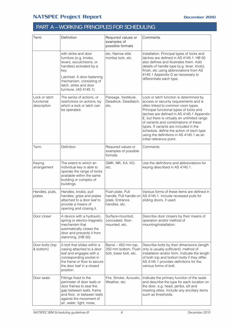
with strike and door furniture (e.g. knobs, levers, escutcheons, or handles) activated by a key.
Latchset: A door-fastening mechanism, consisting of latch, strike and door furniture. (AS 4145.1)
etc, Narrow stile mortise lock, etc.
installation. Principal types of locks and latches are defined in AS 4145.1. HB 50 also defines and illustrates them. Add details of handle type (e.g. lever, knob), finish, etc using abbreviations from AS 4145.1 Appendix D as necessary to differentiate each type.
Lock or latch functional description
The series of actions, or restrictions on actions, by which a lock or latch can be operated.
Passage, Vestibule, Deadlock, Deadlatch, etc.
Lock or latch function is determined by access or security requirements and is often linked to common room types. Principal functional types of locks and latches are defined in AS 4145.1 Appendix E, but there is virtually an unlimited range of variants and combinations of these types. If variants are included in the schedule, define the action of each type using the definitions in AS 4145.1 as an initial reference point.
Term
Definition
Required values or examples of possible formats
Comments
Keying arrangement
The extent to which an individual key is able to operate the range of locks available within the same building or complex of buildings.
GMK, MK, KA, KD, etc.
Use the definitions and abbreviations for keying described in AS 4145.1.
Handles, pulls, plates
Handles, knobs, pull handles, grips and plates attached to a door leaf to provide a means of opening and closing it.
Push plate, Pull handle, Pull handle on plate, Entrance handles, etc.
Various forms of these items are defined in AS 4145.1. Include recessed pulls for sliding doors, if used.
Door closer A device with a hydraulic, spring or electro-magnetic mechanism that automatically closes the door and prevents it from slamming. (HB 50)
Surface-mounted, concealed, floor-mounted, etc.
Describe door closers by their means of operation and/or method of mounting/installation.
Door bolts (top & bottom)
A bolt that slides within a casing attached to a door leaf and engages with a corresponding socket in the frame or floor to secure the door leaf in a closed position.
Barrel – 450 mm top, 250 mm bottom, Flush bolt, tower bolt, etc.
Describe bolts by their dimensions (length only is usually sufficient), method of installation and/or form. Indicate the length of both top and bottom bolts if they differ. AS 4145.1 provides definitions for the various forms of bolt.
Door seals Fittings fixed to the perimeter of door leafs or door frames to seal the gap between leafs, frame and floor, or between leafs against the movement of air, water, light, noise,
Fire, Smoke, Acoustic, Weather, etc.
Indicate the primary function of the seals and describe the type for each location on the door, e.g. head, jambs, sill and meeting stiles. Include any ancillary items such as thresholds.
NATSPEC BIM Scheduling guidelines © 8 December 2010
NATSPEC Project Report December 2010
PART A – WORKING PRINCIPLES FOR SCHEDULING
Term
Definition
Required values or examples of possible formats
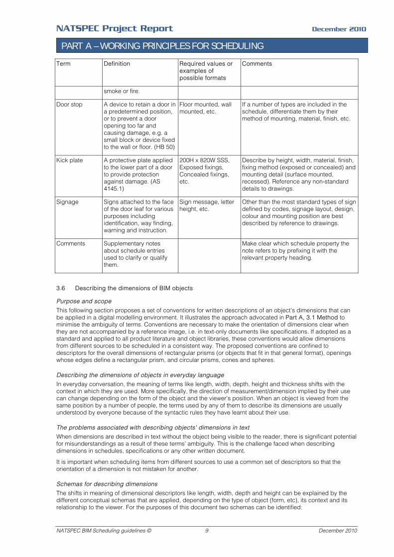
Comments
smoke or fire.
Door stop A device to retain a door in a predetermined position, or to prevent a door opening too far and causing damage, e.g. a small block or device fixed to the wall or floor. (HB 50)
Floor mounted, wall mounted, etc.
If a number of types are included in the schedule, differentiate them by their method of mounting, material, finish, etc.
Kick plate A protective plate applied to the lower part of a door to provide protection against damage. (AS 4145.1)
200H x 820W SSS, Exposed fixings, Concealed fixings, etc.
Describe by height, width, material, finish, fixing method (exposed or concealed) and mounting detail (surface mounted, recessed). Reference any non-standard details to drawings.
Signage Signs attached to the face of the door leaf for various purposes including identification, way finding, warning and instruction.
Sign message, letter height, etc.
Other than the most standard types of sign defined by codes, signage layout, design, colour and mounting position are best described by reference to drawings.
Comments Supplementary notes about schedule entries used to clarify or qualify them.
Make clear which schedule property the note refers to by prefixing it with the relevant property heading.
3.6 Describing the dimensions of BIM objects
Purpose and scope
This following section proposes a set of conventions for written descriptions of an object’s dimensions that can be applied in a digital modelling environment. It illustrates the approach advocated in Part A, 3.1 Method to minimise the ambiguity of terms. Conventions are necessary to make the orientation of dimensions clear when they are not accompanied by a reference image, i.e. in text-only documents like specifications. If adopted as a standard and applied to all product literature and object libraries, these conventions would allow dimensions from different sources to be scheduled in a consistent way. The proposed conventions are confined to descriptors for the overall dimensions of rectangular prisms (or objects that fit in that general format), openings whose edges define a rectangular prism, and circular prisms, cones and spheres.
Describing the dimensions of objects in everyday language
In everyday conversation, the meaning of terms like length, width, depth, height and thickness shifts with the context in which they are used. More specifically, the direction of measurement/dimension implied by their use can change depending on the form of the object and the viewer's position. When an object is viewed from the same position by a number of people, the terms used by any of them to describe its dimensions are usually understood by everyone because of the syntactic rules they have learnt about their use.
The problems associated with describing objects' dimensions in text
When dimensions are described in text without the object being visible to the reader, there is significant potential for misunderstandings as a result of these terms’ ambiguity. This is the challenge faced when describing dimensions in schedules, specifications or any other written document.
It is important when scheduling items from different sources to use a common set of descriptors so that the orientation of a dimension is not mistaken for another.
Schemas for describing dimensions
The shifts in meaning of dimensional descriptors like length, width, depth and height can be explained by the different conceptual schemas that are applied, depending on the type of object (form, etc), its context and its relationship to the viewer. For the purposes of this document two schemas can be identified:
NATSPEC BIM Scheduling guidelines © 9 December 2010
NATSPEC Project Report December 2010
PART A – WORKING PRINCIPLES FOR SCHEDULING
- Proportion-based
- Orientation-based
Proportion based schemas
In the proportion-based schema, descriptors are assigned according to the aspect ratio of the form. The aspect ratio or proportions of a two-dimensional shape is the ratio of its longer dimension to its shorter dimension. It can also be applied to any pair of dimensions of a three-dimensional shape. Length is usually assigned to the largest dimension, and width and depth to the two intermediate dimensions. The ambiguity of width and depth is higher than other terms because of the numerous ways in which they can be applied. Thickness is generally the distance between two parallel faces of an object, when that distance is smallest relative to the object’s other dimensions. It is usually applied to linear and planar forms regardless of orientation.
Orientation based schemas
In the orientation-based schema descriptors are assigned according to the orientation of an object relative to a notional reference plane. Usually this plane is taken as nominally horizontal, corresponding to a level piece of ground or floor. However, in some instances, the descriptors can be applied by reference to a vertical plane, like a wall, or the underside of a horizontal plane, like a ceiling. Height describes the perpendicular distance above the reference plane. Width is generally assigned to the lateral (side-to-side) dimension of an object. Depth is more ambiguous because it can be assigned to either the vertical or front-to-rear dimension of an object.
Note: Breadth is considered equivalent to width for the purposes of this document, and is not used.
Frames of reference for an orientation based schema
A number of frames of reference could be used for defining orientation in an orientation-based schema:
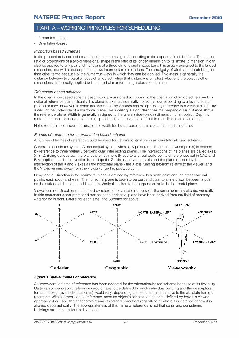
Cartesian coordinate system. A conceptual system where any point (and distances between points) is defined by reference to three mutually perpendicular intersecting planes. The intersections of the planes are called axes: X, Y, Z. Being conceptual, the planes are not implicitly tied to any real world points of reference, but in CAD and BIM applications the convention is to adopt the Z axis as the vertical axis and the plane defined by the intersection of the X and Y axes as the horizontal plane - the X axis running left-right relative to the viewer, and the Y axis running away from the viewer (or up the page/screen).
Geographic. Direction in the horizontal plane is defined by reference to a north point and the other cardinal points: east, south and west. The horizontal plane is taken to be perpendicular to a line drawn between a point on the surface of the earth and its centre. Vertical is taken to be perpendicular to the horizontal plane.
Viewer-centric. Direction is described by reference to a standing person - the spine nominally aligned vertically. In this document descriptors for direction in the horizontal plane have been derived from the field of anatomy: Anterior for in front, Lateral for each side, and Superior for above.
Figure 1 Spatial frames of reference
A viewer-centric frame of reference has been adopted for the orientation-based schema because of its flexibility. Cartesian or geographic references would have to be defined for each individual building and the descriptors for each object (even identical ones) would vary, depending on their orientation relative to the absolute frame of reference. With a viewer-centric reference, once an object's orientation has been defined by how it is viewed, approached or used, the descriptors remain fixed and consistent regardless of where it is installed or how it is aligned geographically. The appropriateness of this frame of reference is not that surprising considering buildings are primarily for use by people.
NATSPEC BIM Scheduling guidelines © 10 December 2010
NATSPEC Project Report December 2010
PART A – WORKING PRINCIPLES FOR SCHEDULING
Possible approaches to formulating a set of conventions
Possible approaches include:
- Single schema: Adopting one schema as the basis for a set of descriptor conventions and applying it rigidly with few exceptions would seem to offer the advantage of consistency. Applying it to all types of objects, however, has its problems. An orientation-based schema would be difficult to apply to unfixed materials because their final installed orientation cannot be known. Applying an orientation-based schema to all installed elements could result in some counter-intuitive results - for example, if Depth is assigned to front-to rear dimensions relative to the viewer it would then be used to describe the thickness of a wall or door leaf.
- Notation system: Adding a qualifying notation to common descriptors would remove any ambiguity from terms like width and depth. For example, DI for Depth (Inferior) indicating depth in a vertical downwards direction, and DA for Depth (Anterior) indicating depth in a horizontal front-to-rear direction (relative to the user or viewer. While this seems to eliminate a significant amount of ambiguity, problems could be anticipated having it widely accepted, implemented and understood by everyone in the construction industry.
- A hybrid proportion-based/orientation-based schema in which both schema, and associated descriptors, are applied, depending on context.
Proposed conventions
Conventions based on a single schema or a notation system have been discarded because of their limitations. The proposed conventions are based on a hybrid schema. This accommodates the large variety of objects found in buildings and their surrounds. The principles proposed can be summarised as follows:
For unfixed materials, use a proportion-based schema:
1. Use length, width and depth for cuboidal forms.
2. Use length, width and thickness for linear or planar forms.
For installed (or ready to install) elements, use a mixed orientation-based/proportion-based schema:
1. Use height, width and depth for cuboidal forms.
2. Use height, length and thickness for vertical planar forms.
3. Use width, length and thickness for horizontal planar forms.
Note: The difference between cuboidal forms and planar forms would need to be defined by an agreed aspect ratio.
While the hybrid schema proposed might initially appear complicated, it would probably be easy to use in practice because it formalises many of the syntactic rules already internalised by the general population.
Descriptor listing order in text (schedules, etc): As a general rule, list the descriptor for the smallest dimension first and that for largest or vertical dimension last.
The following tables (with corresponding illustrations below) show four common classes of building objects, and explains the conventions applicable to each in detail.
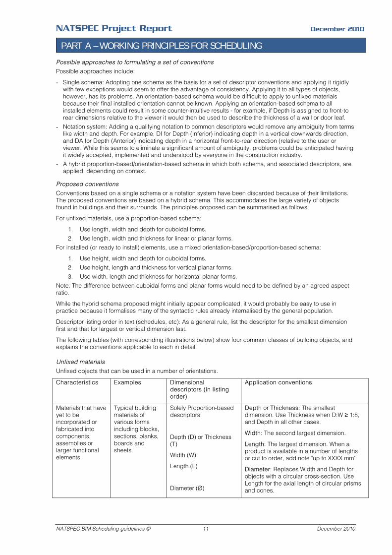
Unfixed materials
Unfixed objects that can be used in a number of orientations.
Characteristics Examples Dimensional descriptors (in listing order)
Application conventions
Materials that have yet to be incorporated or fabricated into components, assemblies or larger functional elements.
Typical building materials of various forms including blocks, sections, planks, boards and sheets.
Solely Proportion-based descriptors:
Depth (D) or Thickness (T)
Width (W)
Length (L)
Diameter (Ø)
Depth or Thickness: The smallest dimension. Use Thickness when D:W ≥ 1:8, and Depth in all other cases.
Width: The second largest dimension.
Length: The largest dimension. When a product is available in a number of lengths or cut to order, add note "up to XXXX mm"
Diameter: Replaces Width and Depth for objects with a circular cross-section. Use Length for the axial length of circular prisms and cones.
NATSPEC BIM Scheduling guidelines © 11 December 2010
NATSPEC Project Report December 2010
PART A – WORKING PRINCIPLES FOR SCHEDULING
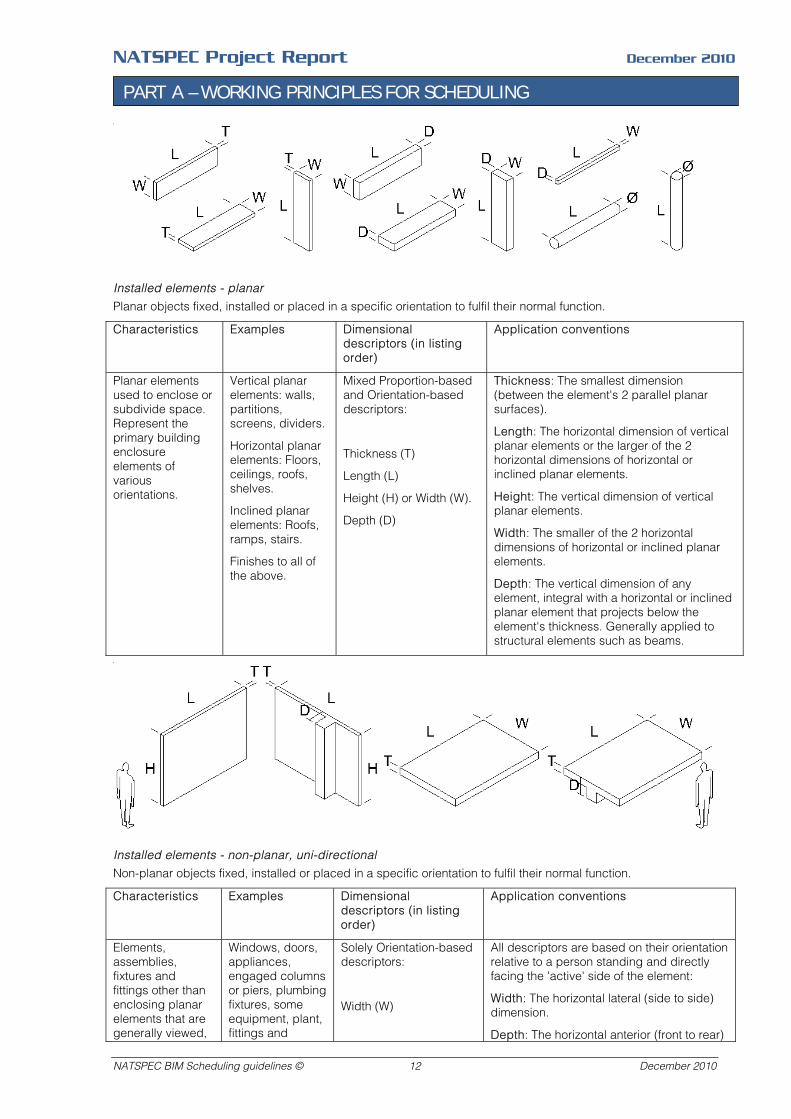
Installed elements - planar
Planar objects fixed, installed or placed in a specific orientation to fulfil their normal function.
Characteristics Examples Dimensional descriptors (in listing order)
Application conventions
Planar elements used to enclose or subdivide space. Represent the primary building enclosure elements of various orientations.
Vertical planar elements: walls, partitions, screens, dividers.
Horizontal planar elements: Floors, ceilings, roofs, shelves.
Inclined planar elements: Roofs, ramps, stairs.
Finishes to all of the above.
Mixed Proportion-based and Orientation-based descriptors:
Thickness (T)
Length (L)
Height (H) or Width (W).
Depth (D)
Thickness: The smallest dimension (between the element's 2 parallel planar surfaces).
Length: The horizontal dimension of vertical planar elements or the larger of the 2 horizontal dimensions of horizontal or inclined planar elements.
Height: The vertical dimension of vertical planar elements.
Width: The smaller of the 2 horizontal dimensions of horizontal or inclined planar elements.
Depth: The vertical dimension of any element, integral with a horizontal or inclined planar element that projects below the element's thickness. Generally applied to structural elements such as beams.
Installed elements - non-planar, uni-directional
Non-planar objects fixed, installed or placed in a specific orientation to fulfil their normal function.
Characteristics Examples Dimensional descriptors (in listing order)
Application conventions
Elements, assemblies, fixtures and fittings other than enclosing planar elements that are generally viewed,
Windows, doors, appliances, engaged columns or piers, plumbing fixtures, some equipment, plant, fittings and
Solely Orientation-based descriptors:
Width (W)
All descriptors are based on their orientation relative to a person standing and directly facing the 'active' side of the element:
Width: The horizontal lateral (side to side) dimension.
Depth: The horizontal anterior (front to rear)
NATSPEC BIM Scheduling guidelines © 12 December 2010
NATSPEC Project Report December 2010
PART A – WORKING PRINCIPLES FOR SCHEDULING
Characteristics Examples Dimensional descriptors (in listing order)
Application conventions
approached, used or serviced from one, or two opposite, directions. Generally items located on, in or against a vertical surface.
furniture including chairs, single sided desks, workstations, etc.
Depth (D)
Height (H)
Diameter (Ø)
Length (L) (circular section objects only)
dimension.
Note: Use Depth to describe overall depth of door and window frames, but use Thickness to describe leaf or glazing thickness as per the convention for planar elements.
Height: The vertical dimension from top to bottom.
Diameter: For objects with a circular cross-section. For the axial length of circular prisms and cones, when the axis is horizontal, use Width and Depth, depending on orientation, as above. Use Height when vertical.
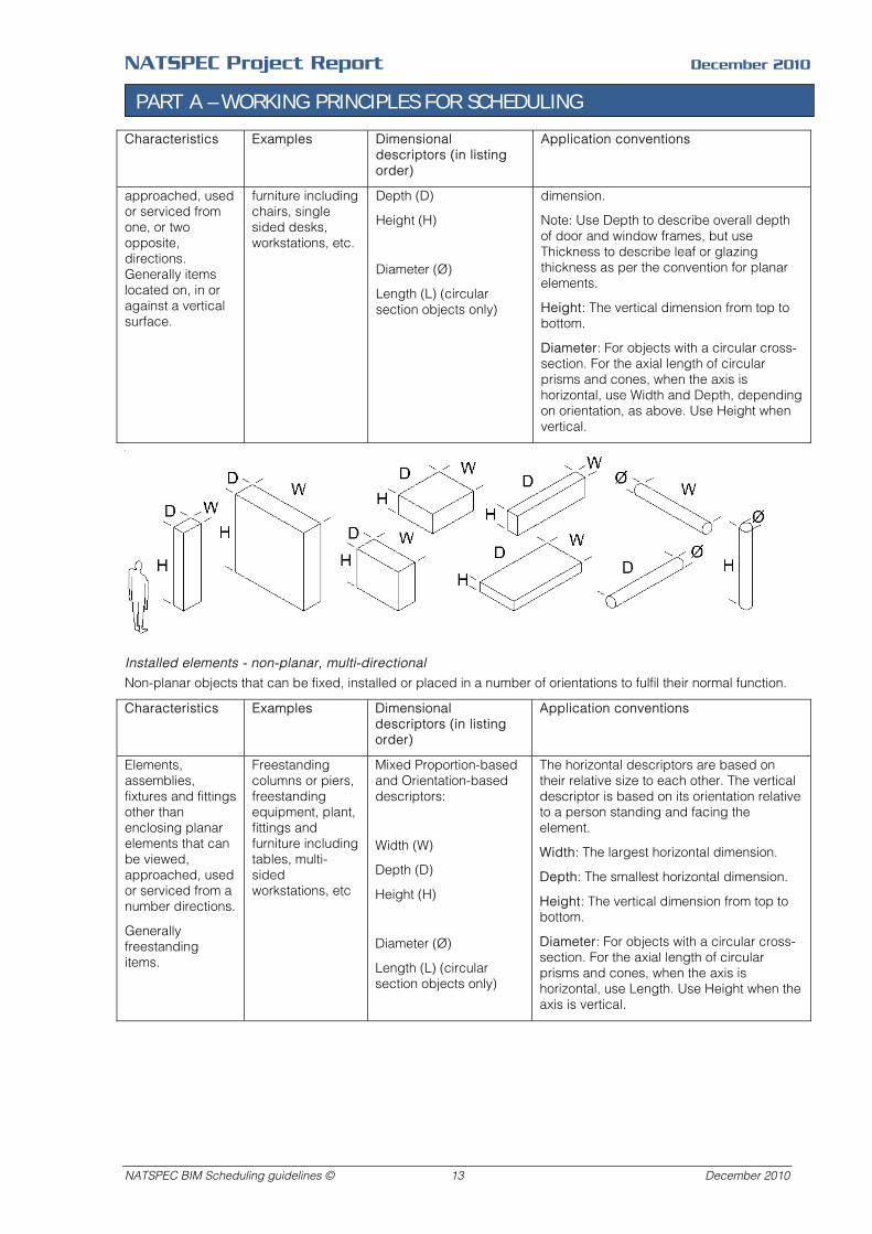
Installed elements - non-planar, multi-directional
Non-planar objects that can be fixed, installed or placed in a number of orientations to fulfil their normal function.
Characteristics Examples Dimensional descriptors (in listing order)
Application conventions
Elements, assemblies, fixtures and fittings other than enclosing planar elements that can be viewed, approached, used or serviced from a number directions.
Generally freestanding items.
Freestanding columns or piers, freestanding equipment, plant, fittings and furniture including tables, multi-sided workstations, etc
Mixed Proportion-based and Orientation-based descriptors:
Width (W)
Depth (D)
Height (H)
Diameter (Ø)
Length (L) (circular section objects only)
The horizontal descriptors are based on their relative size to each other. The vertical descriptor is based on its orientation relative to a person standing and facing the element.
Width: The largest horizontal dimension.
Depth: The smallest horizontal dimension.
Height: The vertical dimension from top to bottom.
Diameter: For objects with a circular cross-section. For the axial length of circular prisms and cones, when the axis is horizontal, use Length. Use Height when the axis is vertical.
NATSPEC BIM Scheduling guidelines © 13 December 2010
NATSPEC Project Report December 2010
PART A – WORKING PRINCIPLES FOR SCHEDULING
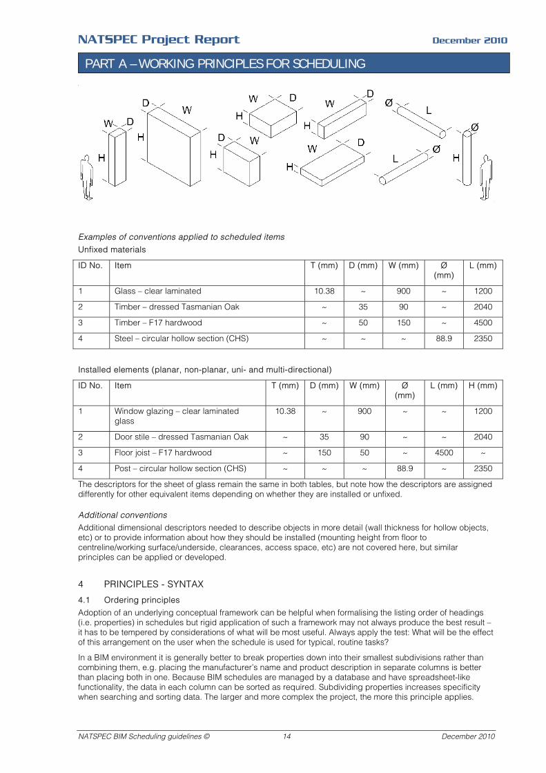
Examples of conventions applied to scheduled items
Unfixed materials
ID No. Item T (mm) D (mm) W (mm) Ø (mm)
L (mm)
1 Glass – clear laminated 10.38 ~ 900 ~ 1200
2 Timber – dressed Tasmanian Oak ~ 35 90 ~ 2040
3 Timber – F17 hardwood ~ 50 150 ~ 4500
4 Steel – circular hollow section (CHS) ~ ~ ~ 88.9 2350
Installed elements (planar, non-planar, uni- and multi-directional)
ID No. Item T (mm) D (mm) W (mm) Ø (mm)
L (mm) H (mm)
1 Window glazing – clear laminated glass
10.38 ~ 900 ~ ~ 1200
2 Door stile – dressed Tasmanian Oak ~ 35 90 ~ ~ 2040
3 Floor joist – F17 hardwood ~ 150 50 ~ 4500 ~
4 Post – circular hollow section (CHS) ~ ~ ~ 88.9 ~ 2350
The descriptors for the sheet of glass remain the same in both tables, but note how the descriptors are assigned differently for other equivalent items depending on whether they are installed or unfixed.
Additional conventions
Additional dimensional descriptors needed to describe objects in more detail (wall thickness for hollow objects, etc) or to provide information about how they should be installed (mounting height from floor to centreline/working surface/underside, clearances, access space, etc) are not covered here, but similar principles can be applied or developed.
4 PRINCIPLES - SYNTAX
4.1 Ordering principles
Adoption of an underlying conceptual framework can be helpful when formalising the listing order of headings (i.e. properties) in schedules but rigid application of such a framework may not always produce the best result – it has to be tempered by considerations of what will be most useful. Always apply the test: What will be the effect of this arrangement on the user when the schedule is used for typical, routine tasks?
In a BIM environment it is generally better to break properties down into their smallest subdivisions rather than combining them, e.g. placing the manufacturer’s name and product description in separate columns is better than placing both in one. Because BIM schedules are managed by a database and have spreadsheet-like functionality, the data in each column can be sorted as required. Subdividing properties increases specificity when searching and sorting data. The larger and more complex the project, the more this principle applies.
NATSPEC BIM Scheduling guidelines © 14 December 2010
NATSPEC Project Report December 2010
PART A – WORKING PRINCIPLES FOR SCHEDULING
4.2 Suggested approach to ordering schedule properties
1. Place identifiers before subclass descriptions, and subclass descriptions before properties.
2. Place alphanumeric codes or tags before the item's title to assist sorting and referencing.
3. Place subclass or subtype descriptions of the class of items being scheduled before properties. The subtype can be defined by a number of criteria including form, function, operation and power source, e.g. sliding, casement, awning, double-hung windows. The subtype directly influences the following property set. Placing the subtype early in the order allows the properties to be tailored to the subtype instead of having to provide a more universal set of properties to accommodate a wider range of possibilities. This usually requires some consideration of the range of possible subtypes that may be needed and establishing naming conventions for them prior to implementing them. This consideration is likely to be required at some stage anyhow, regardless of where the subtype description is placed in the schedule order.
4. Place properties that are usually decided earlier in the design process before properties that are decided later, e.g. door handing before panel type and finishes.
5. Place general properties before special properties.
6. Place salient properties before detailed properties.
7. Place more common or frequently used class properties before less common or infrequently used class properties. This means that when items are compiled in the schedule, entries appear more homogenous on the left, and become increasingly varied as they move to the right. This gradation makes locating similarities and differences between items an easier task.
8. Place properties associated with an assembly as a whole before properties of its components.
9. Place properties associated with the primary or essential components of an assembly before ancillary or optional components. Order the properties for each component in turn.
10. Schedule the components of an assembly in general order of assembly or placement, e.g. framing before lining, substrate before finish, or consistently apply another principle noted in Part B, 3 Information ordering. Then list the properties associated with each component in the order recommended above.
4.3 Recommended scheduling order
The general principles above have been applied in the formulation of following recommendations for ordering properties:
Identifiers
1. ID code – instance. A code for identifying an individual item, e.g. each window.
2. ID code – type. A code for identifying a particular type of item, e.g. each partition type.
3. Name. A brief identifying label or short description, e.g. room name.
4. Location. This function may be filled by location-based names like room names. If the location is identified by a room name, for example, use the location field to identify a more specific location within the room, e.g. north wall, ceiling, floor, above ceiling.
Descriptors - generic
5. Description. A brief statement that gives the reader a clear picture of an item. Its main function is explanatory. For example, to describe a product identified by product number only that would otherwise be meaningless to the reader. Beware of duplicating the individual properties following. If its content is fully described by other properties and does not add value (by reducing ambiguity, etc), omit it. The name (Item 3), which is often a short description of an item, may be adequate.
6. Type. A significant subtype of the class of items being scheduled, e.g. for a window schedule: sliding, casement, awning, double-hung. See the notes under Part B, 3 Information ordering. It can take the form of a written description or a code that can be interpreted by means of an associated legend.
Manufacturer: Insert the manufacturer’s name. If it is not known, or the project is being documented on a non-proprietary, performance basis, insert ‘Generic”.
Descriptors - proprietary
Insert the following fields if a proprietary method of specifying items is being used:
7. Manufacturer
8. Product name.
NATSPEC BIM Scheduling guidelines © 15 December 2010

NATSPEC Project Report December 2010
PART A – WORKING PRINCIPLES FOR SCHEDULING
9. Product range or series.
10. Product reference number.
11. Product supplier name and contact details.
12 Product image.
13. Product data sheet. Incorporate a pdf file or hyperlink. Other options include a pdf file or hyperlink to material safety data sheets (MSDS) and installation, operation, cleaning and maintenance instructions. The inclusion of these items will depend on the intended recipients of the schedule, the capabilities of the modelling application and considerations such as the size of the resulting file. Depending on the approach to documentation for the project, detailed product data is generally better located in the specification.
Properties
14. Properties – dimensional. Width, Height, Depth. Define the basis of measurement if it is unclear how these should be measured. Include the unit of measurement in the heading within brackets, e.g. (mm).
15. Properties – physical and/or visual. Material, finish, colour, pattern. Can also include physical configuration: hinged, sliding, etc.
16. Properties – rated performance. E.g. fire rating, acoustic rating, IP rating, slip resistance, durability class. Although related to 'Properties - physical performance', rated performance is based on a prescribed regime of measurements and/or tests rather than direct simple measurement. They have been placed before 'Properties - physical performance' because they often provide a better overall indicator of performance in practice and/or as installed. For example, place a WERS rating for a window before individual R-values for its glazing and frame. Likewise, the total R-value of the window frame gives a broader indicator of performance than the thermal conductivity properties of its constituent materials. Note: Precedence does not imply importance. The thermal conductivity properties of the constituent materials may be necessary for thermal analysis. Make sure that values entered for rated performance do not contradict those entered for physical performance. Omitting one or the other may be necessary to eliminate this possibility. Include the rating criteria in the heading.
17. Properties – physical performance. Intrinsically associated with, and relevant to the material properties of the item being scheduled, e.g. voltage, flow rate, cooling capacity, light output. These properties can be directly measured or tested and expressed as simple relationships between units of measurement, e.g. kg/m2. Include the unit of measurement in the heading within brackets, e.g. (kW/hr).
18. Properties - rating scheme score. The item's performance expressed as a dimensionless figure, point score or performance category based on a rating scheme, and representing an assessment based on wide range of criteria, e.g. Green Star. They have parallels to 'Properties - rated performance' but differ in that they are more global and relate to an assessment of the project as a whole, rather than properties of individual items. In projects subject to a rating scheme it might be more appropriate to link some items using 'Sorting references'. Include the rating scheme and rating category in the heading.
Referencing
19. Sorting references codes. These are notations or codes used to sort or filter scheduled items for some purpose – sometimes called assembly codes. They can be from an established classification system for sorting the scheduled items into that system’s order, e.g. NATSPEC codes for sorting items into specification worksection groups or Australian Cost Management Manual (ACMM) notations for grouping building elements and sub-elements in cost plans. Include the name of the classification scheme in the heading. Other types of codes used to sort items in a global manner include provision codes for identifying who is responsible for the supply and installation of items in a project. For example, Group numbers used by health authorities: Group 1: Provided and installed by the builder, Group 2: Provided by the client and installed by the builder, Group 3: Provided and installed by the client. Similar codes can be used to identify which items are to be relocated, reused, recycled or disposed of. Provide a legend for interpreting codes unique to the project. Sorting codes can also be used for administration or display purposes. One code can be used to indicate/sort items that are to be displayed in documents, and another to indicate items that have to be checked before their display is authorised. See notes on Administrative notes.
20. Documentation cross references. These are used to indicate locations where the scheduled item is referred to elsewhere in the documents. They are navigation aids to help users find the information they need, e.g. drawing numbers, detail drawing numbers, specification worksection numbers.
Quantities and costing
21. Quantities. Can be a single field to show the total quantity of an item or a series of fields for calculation purposes, e.g. unit, quantity, rate, amount. Set up sum (totalling) fields to calculate quantities in the desired format, e.g. for all items, or for subsets of items. The format of the schedule (e.g. ‘every instance itemised’) will
NATSPEC BIM Scheduling guidelines © 16 December 2010
NATSPEC Project Report December 2010
PART A – WORKING PRINCIPLES FOR SCHEDULING
often determine this. Append any conditions, qualifications or assumptions associated with measurement, as appropriate.
22. Costing. Can be a single field to show the total cost of an item or a series of fields for calculation purposes, e.g. unit, quantity, rate, amount. Incorporate the currency symbol adjacent each total amount or in the heading within brackets, e.g. ($A). Append any conditions, qualifications or assumptions associated with costing, as appropriate. Include notes about when costing is to be displayed or hidden. Quantity and costing fields can be combined if preferred.
Comments
23. Comments, remarks. Notes on any issue relevant to the item, e.g. any variation to an otherwise standard property, special requirements, installation details. This field can act as a ‘catch all’ for any matter deemed significant. It should be made clear which notes are intended for general distribution, e.g. the client and other consultants, and those which are intended for reference by the authors of the schedule only (for reminders, quality control, etc). See Administrative notes below. The distinction can be made clear by means of notes or graphic devices like heavier dividing lines between cells or applied tones.
Administrative notes
Use the following fields to indicate the status of a schedule item with regard to approvals, authorisations or program. They are generally applied to the schedule as a whole – in which case they appear outside schedule in the title block, footer, etc, but are sometimes applied to each scheduled item when this degree of tracking is required. Amendments to the previous issue of the schedule should be clearly indicated by devices such as revision clouds, coloured text or applied tones – they are easily missed if this is not done.
24. Revision number. To office numbering system.
25. Issue date. Nominate format used by office: DD/MM/YYYY, DD.MM.YYYY, YYYYMMDD, etc,
26. Notes (administrative). e.g. schedule items are to be displayed or hidden such as costings and approvals.
27. Status. Preliminary, for tender, for construction, etc
28. Approved by. Name or initials with legend.
29. Checked by. Name or initials with legend.
5 PRINCIPLES - PROTOCOLS
5.1 Exchanging data with others
Information flows over the duration of the project must be analysed before protocols for exchanging data between members of the project team can be formalised. The information requirements of each party at each stage need to be analysed and agreed. Guidance on formulating frameworks for data exchange throughout a project is beyond the scope of this report – it is more concerned with the principles applied to finer scale exchanges within such a framework. Documents that provide guidance on such frameworks - often referred to as Model Progression Specifications (MPS) - include Integrated Project delivery: A Guide published by the Californian division of AIA. Contractual documents used to formalise the responsibilities of project team members regarding data exchange have been developed for this purpose and include the AIA Document E202 BIM Protocol Exhibit – 2008.
5.2 The use of schedules for exchanging data
The following schedules and commentaries illustrate the principles outlined in Part B 4 Using schedules for data exchange. Schedules for two different types of items are featured – fans and door hardware.
5.3 Example 1 - Exchanging information about a fan
Three schedules have been included to illustrate how schedules can be used as a vehicle for the exchange of information about a fan by a mechanical services consultant and a contractor. The following commentary describes the process by reference to each schedule:
Consultant’s requirements
The mechanical consultant fills in the performance requirements for a fan (Supply Fan SF1) using a schedule from the NATSPEC 0731 Fans worksection (Schedule 1 on the next page) The completed schedule is sent to the mechanical contractor with supporting information such as a list of fan manufacturers acceptable to the consultant.
NATSPEC BIM Scheduling guidelines © 17 December 2010
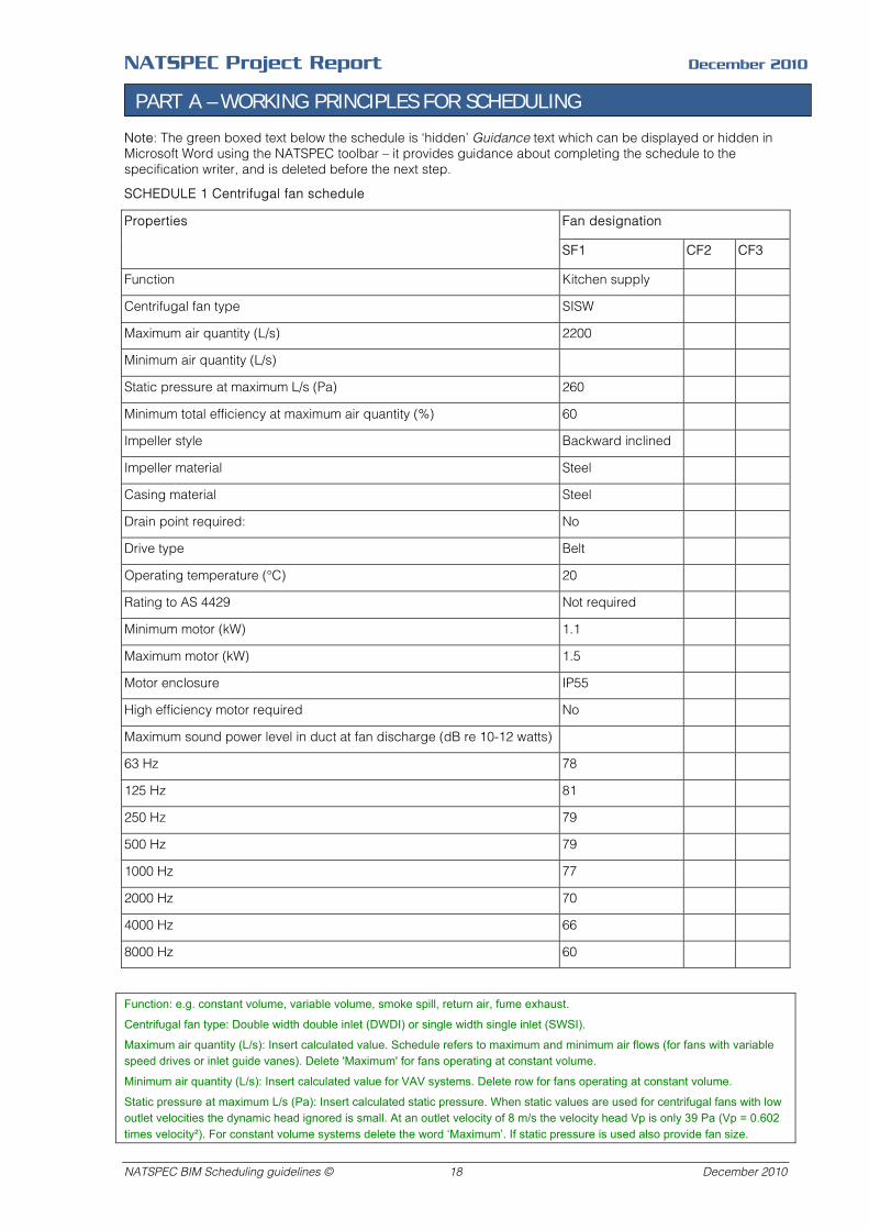
NATSPEC Project Report December 2010
PART A – WORKING PRINCIPLES FOR SCHEDULING
Note: The green boxed text below the schedule is ‘hidden’ Guidance text which can be displayed or hidden in Microsoft Word using the NATSPEC toolbar – it provides guidance about completing the schedule to the specification writer, and is deleted before the next step.
SCHEDULE 1 Centrifugal fan schedule
Fan designation Properties
SF1 CF2 CF3
Function Kitchen supply
Centrifugal fan type SISW
Maximum air quantity (L/s) 2200
Minimum air quantity (L/s)
Static pressure at maximum L/s (Pa) 260
Minimum total efficiency at maximum air quantity (%) 60
Impeller style Backward inclined
Impeller material Steel
Casing material Steel
Drain point required: No
Drive type Belt
Operating temperature (°C) 20
Rating to AS 4429 Not required
Minimum motor (kW) 1.1
Maximum motor (kW) 1.5
Motor enclosure IP55
High efficiency motor required No
Maximum sound power level in duct at fan discharge (dB re 10-12 watts)
63 Hz 78
125 Hz 81
250 Hz 79
500 Hz 79
1000 Hz 77
2000 Hz 70
4000 Hz 66
8000 Hz 60
Function: e.g. constant volume, variable volume, smoke spill, return air, fume exhaust.
Centrifugal fan type: Double width double inlet (DWDI) or single width single inlet (SWSI).
Maximum air quantity (L/s): Insert calculated value. Schedule refers to maximum and minimum air flows (for fans with variable speed drives or inlet guide vanes). Delete 'Maximum' for fans operating at constant volume.
Minimum air quantity (L/s): Insert calculated value for VAV systems. Delete row for fans operating at constant volume.
Static pressure at maximum L/s (Pa): Insert calculated static pressure. When static values are used for centrifugal fans with low outlet velocities the dynamic head ignored is small. At an outlet velocity of 8 m/s the velocity head Vp is only 39 Pa (Vp = 0.602 times velocity²). For constant volume systems delete the word ‘Maximum’. If static pressure is used also provide fan size.
NATSPEC BIM Scheduling guidelines © 18 December 2010
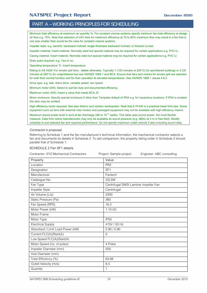
NATSPEC Project Report December 2010
PART A – WORKING PRINCIPLES FOR SCHEDULING
Minimum total efficiency at maximum air quantity %: For constant volume systems specify minimum fan total efficiency at design air flow e.g. 75%. Note that selection of VAV fans for maximum efficiency at 70 to 80% maximum flow may result in a fan that is one size smaller than would be the case for constant volume systems.
Impeller style: e.g. aerofoil, backward inclined; single thickness backward inclined; or forward curved.
Impeller material: Insert material. Normally steel but special material may be required for certain applications e.g. PVC-U.
Casing material: Insert material. Normally steel but special material may be required for certain applications e.g. PVC-U.
Drain point required: e.g. Yes or no.
Operating temperature ℃: Insert temperature.
Rating to AS 4429: For smoke spill fans - delete otherwise. Typically 1 (120 minutes at 200°C) for sprinklered buildings or 2 (30 minutes at 300°C) for unsprinklered but see AS/NZS 1668.1 and BCA. Ensure that fans and motors for smoke spill are selected for both their normal function and for their operation at elevated temperatures. See AS/NZS 1668.1 clause 4.8.2.
Drive type: e.g. belt, direct drive, variable speed, two speed.
Minimum motor (kW): Select to suit fan duty and documented efficiency.
Maximum motor (kW): Insert a value that meets BCA J5.
Motor enclosure: Specify special enclosure if other than Template default of IP54 e.g. for hazardous locations. If IP54 is suitable this item may be omitted.
High efficiency motor required: See also Motors and starters worksection. Note that 0.75 kW is a practical lower limit size. Some equipment such as fans with external rotor motors and packaged equipment may not be available with high efficiency motors.
Maximum sound power level in duct at fan discharge (dB re 10-12 watts): This table uses sound power, the most flexible measure. Data from some manufacturers may only be available as sound pressure (e.g. dB(A) at 3 m in free field). Modify schedule to suit selected fan and required performance. Do not specify maximum outlet velocity if also including sound data.
Contractor’s proposal
Referring to Schedule 1 and the fan manufacturer’s technical information, the mechanical contractor selects a fan and documents its details in Schedule 2. To aid comparison, the property listing order in Schedule 2 should parallel that of Schedule 1.
SCHEDULE 2 Fan SF1 details
Contractor: XYZ Mechanical Contractors Project: Sample project Engineer: ABC consulting
Property Value
Location PR2
Designation SF1
Manufacturer Fantech
Catalogue No. 22LSW
Fan Type Centrifugal SWSI Laminar Impeller Fan
Impeller Style Centrifugal
Air Volume (L/s) 2200
Static Pressure (Pa) 260
Fan Speed (RPS) 16.2
Motor Power (kW) 1.10 (0)
Motor Frame Motor Type IP55
Electrical Supply 415V / 50 Hz
Absorbed / Limit Load Power (kW) 0.90 / 0.90
Current FLC(A)/Start(A) 0
Low Speed FLC(A)/Start(A) Motor Speed (no. of poles) 4 Poles
Impeller Diameter (mm) 559
Hub Diameter (mm)
Total Efficiency (%) 63.68
Outlet Velocity (m/s) 8.4
Quantity 1
NATSPEC BIM Scheduling guidelines © 19 December 2010

NATSPEC Project Report December 2010
PART A – WORKING PRINCIPLES FOR SCHEDULING
Sound Pressure Level dB(A) 59 @ 3m
dBW inlet side - 63 HZ 74
dBW inlet side - 125 HZ 79
dBW inlet side - 250 HZ 77
dBW inlet side - 500 HZ 78
dBW inlet side - 1000 HZ 76
dBW inlet side - 2000 HZ 68
dBW inlet side - 4000 HZ 63
dBW inlet side - 8000 HZ 57
Fan Weight (kg) n/a
Manufacturer’s supporting information
This schedule is an excerpt from the fan manufacturer’s technical information with the relevant points on the product’s performance curves marked.
Finally, the mechanical contractor sends Schedules 2 and 3 to the consultant. They should include sufficient product details and key performance details to clearly demonstrate that the proposed fan meets the consultant’s requirements.
SCHEDULE 3 Manufacturer’s product data
NATSPEC BIM Scheduling guidelines © 20 December 2010
NATSPEC Project Report December 2010
PART A – WORKING PRINCIPLES FOR SCHEDULING
5.4 Example 2 - Exchanging door hardware information
Few architects have the time and inclination to produce an accurate door-by-door hardware schedule for anything other than the simplest project – this task is best left to a hardware specialist, usually associated with the supplier or manufacturer.
For them to schedule the door hardware, they need to be briefed about the specific requirements of the project and the architect’s preferences.
One way of doing this is to identify typical door types found in the building and outline the hardware requirements for each in a door hardware selection schedule. Door types are often determined by the function of the space they serve, so the sample schedule included with this article has been organised on this basis.
The following commentary describes how a series of schedules can be used in the door hardware procurement process:
Schedule 1 – Door hardware selection schedule
This selection schedule is an example of the type that can be given to door hardware specialists, together with a set of general arrangement drawings, for them to prepare a door-by-door hardware schedule. The ideal format for a selection schedule is an Excel or similar spreadsheet.
Key elements of the sample schedule include:
Project details
- Project name: Identifies the project.
- Project location: The project's environment determines corrosivity categories, security risk, etc - factors influencing hardware selection.
- Building description: The building type, class, use and market sector will suggest the appropriate durability, standard of finish and style of hardware required.
- Drawing references: Drawing issue numbers and dates provide a reference point for any amendments made after the preparation of the initial door-by-door schedule and reduce the risk of disputes over the accuracy of the door schedule.
Door hardware requirements
- Outlines the architect's preferences for the hardware range (embodying style, quality standard, etc) and finishes of salient hardware items.
Door and door hardware details
- Describes the properties of doors (leaf and frame type, FRL, etc) proposed for each room type and the required properties of door hardware. It also describes performance requirements for a number of criteria described in AS 4145.1. If the architect is unsure of the appropriate level of performance for each criterion, or how these relate to the hardware products selected, this can be clarified through discussions with the hardware supplier or manufacturer.
Schedule abbreviations
- These legends provide information for interpretation of abbreviations used in the main schedule.
Notes
- Provide information about the interpretation or use of the selection schedule, general information relevant to the project, or instructions to the person preparing the door hardware schedule. For example, the task of designating door handing is assigned to the hardware supplier. This saves duplication of effort and places the responsibility for correct designation on the supplier.
References
- Identifies the source of terminology used in the schedule and the reference standard for performance criteria.
NATSPEC BIM Scheduling guidelines © 21 December 2010
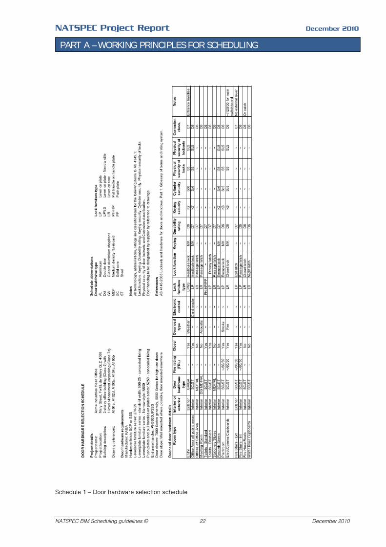
NATSPEC Project Report December 2010
PART A – WORKING PRINCIPLES FOR SCHEDULING
Schedule 1 – Door hardware selection schedule
NATSPEC BIM Scheduling guidelines © 22 December 2010
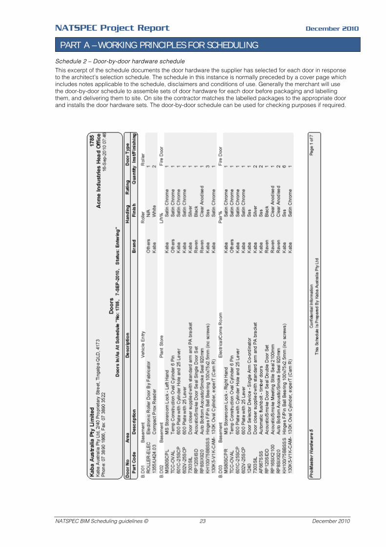
NATSPEC Project Report December 2010
PART A – WORKING PRINCIPLES FOR SCHEDULING
Schedule 2 – Door-by-door hardware schedule
This excerpt of the schedule documents the door hardware the supplier has selected for each door in response to the architect’s selection schedule. The schedule in this instance is normally preceded by a cover page which includes notes applicable to the schedule, disclaimers and conditions of use. Generally the merchant will use the door-by-door schedule to assemble sets of door hardware for each door before packaging and labelling them, and delivering them to site. On site the contractor matches the labelled packages to the appropriate door and installs the door hardware sets. The door-by-door schedule can be used for checking purposes if required.
NATSPEC BIM Scheduling guidelines © 23 December 2010
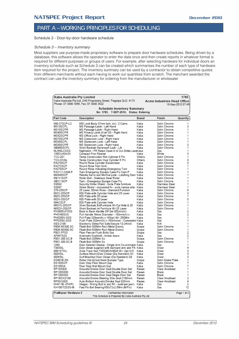
NATSPEC Project Report December 2010
PART A – WORKING PRINCIPLES FOR SCHEDULING
Schedule 2 - Door-by-door hardware schedule
Schedule 3 – Inventory summary
Most suppliers use purpose-made proprietary software to prepare door hardware schedules. Being driven by a database, this software allows the operator to enter the data once and then create reports in whatever format is required for different purposes or groups of users. For example, after selecting hardware for individual doors an inventory schedule such as Schedule 3 can be created which summarises the number of each type of hardware item required for the project. The inventory summary can be used by a contractor to obtain competitive quotes from different merchants without each having to work out quantities from scratch. The merchant awarded the contract can use the inventory summary for ordering from the manufacturer or wholesaler.
NATSPEC BIM Scheduling guidelines © 24 December 2010
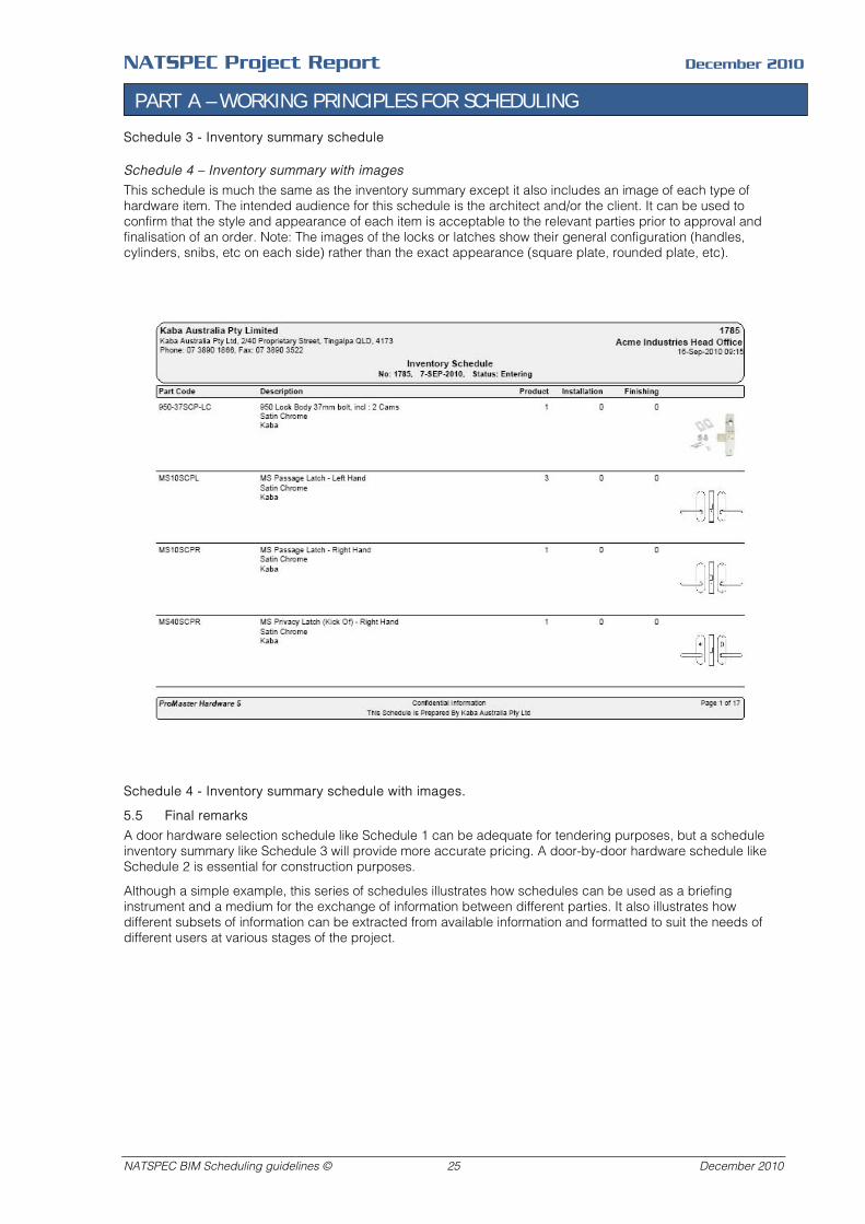
NATSPEC Project Report December 2010
PART A – WORKING PRINCIPLES FOR SCHEDULING
Schedule 3 - Inventory summary schedule
Schedule 4 – Inventory summary with images
This schedule is much the same as the inventory summary except it also includes an image of each type of hardware item. The intended audience for this schedule is the architect and/or the client. It can be used to confirm that the style and appearance of each item is acceptable to the relevant parties prior to approval and finalisation of an order. Note: The images of the locks or latches show their general configuration (handles, cylinders, snibs, etc on each side) rather than the exact appearance (square plate, rounded plate, etc).
Schedule 4 - Inventory summary schedule with images.
5.5 Final remarks
A door hardware selection schedule like Schedule 1 can be adequate for tendering purposes, but a schedule inventory summary like Schedule 3 will provide more accurate pricing. A door-by-door hardware schedule like Schedule 2 is essential for construction purposes.
Although a simple example, this series of schedules illustrates how schedules can be used as a briefing instrument and a medium for the exchange of information between different parties. It also illustrates how different subsets of information can be extracted from available information and formatted to suit the needs of different users at various stages of the project.
NATSPEC BIM Scheduling guidelines © 25 December 2010

NATSPEC Project Report December 2010
PART B – SCHEDULE CONCEPTS
PART B – SCHEDULE CONCEPTS
1 BASICS
1.1 Definition
HB 50 defines Schedule (items) as:
- ‘Tabulated information on a range of similar items in a project which differ in detail, such as door schedule, window schedule, etc.’
This is the meaning ascribed to the term for this project, as distinct from a timetable or program.
1.2 Function/role
Schedules usually function to collect detailed – usually written – information about multiple instances of similar items in a compact format. They often provide an extract of detailed information useful to a specific group of users. For example, a door schedule provides a consolidated summary of the details of all doors in a project that can be used by a door manufacturer to assemble an order.
Schedules can also be used to gather together information that is scattered throughout a set of documents to provide a co-ordinating overview of that information, e.g. Finishes, Fixtures and Equipment schedules that summarise these items on a room-by-room basis. Sometimes schedules are used as a tool to co-ordinate documents themselves rather than the items documented.
1.3 Defining characteristics
Property-value pairs
The fundamental relationship embodied in a schedule for a class of items is:
Item – Property – Value
That is, an item can be characterised by a class to which it belongs and a set of property-value pairs.
A synonymous term for item is object – particularly when used in the context of BIM – where many of the items being scheduled are model ‘objects’.
A schedule, by definition, includes more than one item. Most schedules include more than one property for each item.
Properties and attributes
The terms property, characteristic, attribute and parameter are often used interchangeably and rather loosely. They can be strictly defined, particularly in the domain of computer programming, but the definitions vary with programming language and methodology.
In the interests of consistency this document has adopted the definitions for attribute and property given in ISO/IEC Guide 77-1:2008. This Guide covers topics such as data exchange for product/object libraries, and references standards associated with IFC and IFD, and the EXPRESS modelling language used for both.
Definitions from ISO/IEC Guide 77:2008
Attribute: Data element for the computer-sensible description of a property, a relation or a class.
Note: An attribute describes only one single detail of a property, of a class or of a relation.
Example: The name of a property, the code of a class, the measure unit in which values of a property are provided are examples of an attribute.
Property: A defined parameter suitable for the description and differentiation of products.
Note 1: A property describes one aspect of a given object.
Note 2: A property is defined by the totality of its associated attributes.
1.4 Schedule elements
Title
The schedule title identifies the class of item that is scheduled, e.g. door. Schedules can be used to describe one type of item, e.g. door, fan, pump, or multiple types, e.g. finishes. What is scheduled and the format this scheduling takes is best determined by what will be most useful to the intended users. For BIM derived schedules the name and content will be derived from the objects scheduled.
NATSPEC BIM Scheduling guidelines © 26 December 2010
NATSPEC Project Report December 2010
PART B – SCHEDULE CONCEPTS
Identifiers
Items in schedules are identified by name and/or abbreviated notations (usually alphanumeric). Even though an item may have properties identical to other items, the identifier delineates it as a unique instance of that item type, separate and distinct from all others. An abbreviated identifier, or ‘tag’, has the advantage of not requiring the item’s name to be written in full each time it is referred to, and a short tag can be attached to individual items on a drawing without taking up much drawing space or obscuring other drawn elements. Including an item’s tag in a schedule and on drawings facilitates the co-ordination of both.
Grid
Schedules are laid out in a tabular, or gridded, format with items listed along one axis and properties along the other. (For the purposes of describing schedules in this guide the arrangement of listing items vertically in the left hand column and properties horizontally along the top row has been assumed, although in practice this format can be reversed as required.) The value for each property of an item is placed in the cell located at the intersection of the ‘item’ row with the ‘property’ column. The gridded format makes it very easy to cross-reference information and to compare the differences and similarities between each item. The grid is not always drawn – it is sometimes implied by the layout of text or images.
Ancillaries
Useful ancillary elements – placed outside the schedule – include:
- A set of definitions for the terms used in the schedule. The source of terminology or formatting used for the schedule, i.e. reference documents, can also be identified here.
- A legend or explanatory table to assist the interpretation of abbreviations, codes, tags or other conventions used in the schedule.
- Notes on generalities which describe properties common to all items scheduled, e.g. all items are by the same manufacturer, or have the same finish. This saves having to repeat the same information for every item. The convention of writing ‘UNO.’ (unless noted otherwise) is an expression of this concept. (By identifying the similarity of all items in one place, the differences between items are highlighted in the body of the schedule.
- Cross-references to the specification worksections or drawings relevant to the content of the schedule, or on which the schedule relies.
- A comments or remarks column or row which allows qualifying notes to be made about a particular item, special arrangements applicable to an item, or to describe another property not shared with other items.
1.5 Advantages
Compactness
Schedules allow similar information about a chosen class of items to be displayed in a condensed form that facilitates locating and comparing that information. It makes it easier to locate and check information when creating, editing or using a schedule. The convention of relating a column or row heading to each cell in the same column or row produces a very compact format. It is the framework provided by a gridded format that makes it easier to compare the differences and similarities between each item than if the same information was provided in a single body of text.
Co-ordination
By identifying each item with a unique code in a schedule and on the drawings (and/or the model) information in both documents can be accurately co-ordinated. This device is particularly useful for maintaining the integrity of information during the inevitable amendments that occur during the design development and construction processes.
Data exchange
Because information attached to objects in a digital model can be exported as a spreadsheet or database file, and information in a spreadsheet or database file can be imported into a model to update it, schedules, which follow the same tabulated format of these files, offer a unique means of data exchange. This means information in the model can be extracted in a format readily accessible to users without them having to operate or understand a BIM application. A spreadsheet/ database/ schedule can be used for data entry or revision by non modellers and imported back into the model to update it.
1.6 Limitations
Not all information is appropriate for display in a schedule. Significant amounts of specification text such as statements on quality, workmanship and procedures are not readily accommodated in schedules. They are general statements that apply to the project or sections of work as a whole, so the value of a schedule – the display of a range of similar items – is lost for this purpose.
NATSPEC BIM Scheduling guidelines © 27 December 2010
NATSPEC Project Report December 2010
PART B – SCHEDULE CONCEPTS
1.7 Forms
Tabular
Comprised of largely written information contained within the cells of a rectangular grid. Headings in the top row and side column of the table assist the identification and comparison of information about each item scheduled.
Drawn
Comprised of a graphic representation (plan, elevation, etc) of a group of similar items. For example, an elevation of each type of window in a project is drawn as a group. They are generally shown as stand-alone components without adjacent wall finishes. A drawn window schedule represents a visual inventory of each type and number of window to be included in the project. A window number for each window in the drawn schedule and a corresponding number tag on the general arrangement drawings allows of each window to be located in the project. The inclusion of reference symbols at head, sill and jambs allows the construction details at each of these locations to be cross-referenced to the relevant detail drawing.
Hybrid
A combination of tabular and drawn. Images and graphics can be included within the cells of tabular schedules or tabular information following a consistent format can be associated with drawn schedules. Room data sheets often combine tabulated and drawn information.
This document is concerned with forms that are predominantly tabular.
1.8 Types
Instance schedules
Schedule every instance of a specific class of item. The are generally used for scheduling clearly defined, discrete components or proprietary products that are brought to site as pre-manufactured items and installed, e,g, windows, luminaires, sanitary fixtures, chillers. The total number of individual items is included in the schedule. Each scheduled item has a corresponding tagged item displayed in the model and shown on the drawings.
Type schedules
Schedule every type or subtype included in a class of item, but not every instance of that type. The are generally used for scheduling major elements of composite construction that is usually constructed on site, e,g, roofs, walls, partitions, ceilings, floors, finishes. Because they form larger scale, continuous elements, it is often difficult to subdivide them into separate meaningful parts for the purpose of scheduling. This type of schedule often functions as a legend that shows the details of an item type tagged in the model or on the drawings.
Single class (or category) schedules
Schedule a single class of item. Examples of these include window and sanitary fixture schedules. They are useful if a large number of items from a given class have to be scheduled. Because all items belong to the same class they usually share a smaller property set than multi-class schedules which have to accommodate the range of properties spanning different classes of items.
Multi-class (or category) schedules
Schedule a number of classes of item. Examples of these include fixture, furniture and equipment schedules and finishes schedules that show the different finishes used on every surface of a project. They consolidate information that might otherwise be scattered throughout a number of documents and are useful for providing a comprehensive and co-ordinated overviews of a project. Because of their wide scope, they often make extensive use of coding which needs to be interpreted via associated legends. In this sense, the large bulk of information is handled by breaking it into a series of nested schedules.
2 PLANNING
2.1 Considerations at project inception
Schedules need to be considered as part of the initial information and documentation planning of a project. Planning considerations can be summarised under the following headings:
Appropriateness
Is a schedule the most appropriate means of describing a group of items? If most items in the group are the same except for a small number of variations, it may be simpler and clearer to specify the group by common properties and note individual differences, rather than creating a schedule. If this approach is taken, information
NATSPEC BIM Scheduling guidelines © 28 December 2010
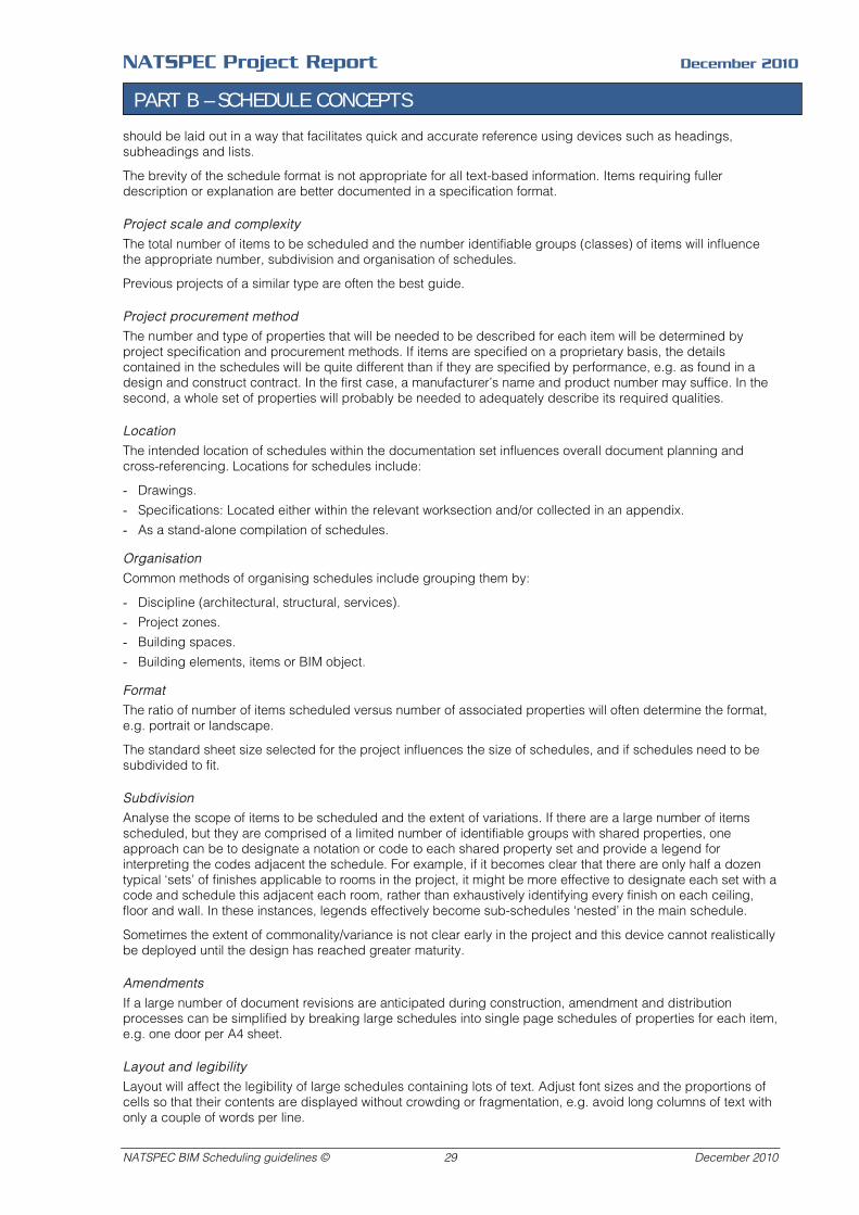
NATSPEC Project Report December 2010
PART B – SCHEDULE CONCEPTS
should be laid out in a way that facilitates quick and accurate reference using devices such as headings, subheadings and lists.
The brevity of the schedule format is not appropriate for all text-based information. Items requiring fuller description or explanation are better documented in a specification format.
Project scale and complexity
The total number of items to be scheduled and the number identifiable groups (classes) of items will influence the appropriate number, subdivision and organisation of schedules.
Previous projects of a similar type are often the best guide.
Project procurement method
The number and type of properties that will be needed to be described for each item will be determined by project specification and procurement methods. If items are specified on a proprietary basis, the details contained in the schedules will be quite different than if they are specified by performance, e.g. as found in a design and construct contract. In the first case, a manufacturer’s name and product number may suffice. In the second, a whole set of properties will probably be needed to adequately describe its required qualities.
Location
The intended location of schedules within the documentation set influences overall document planning and cross-referencing. Locations for schedules include:
- Drawings.
- Specifications: Located either within the relevant worksection and/or collected in an appendix.
- As a stand-alone compilation of schedules.
Organisation
Common methods of organising schedules include grouping them by:
- Discipline (architectural, structural, services).
- Project zones.
- Building spaces.
- Building elements, items or BIM object.
Format
The ratio of number of items scheduled versus number of associated properties will often determine the format, e.g. portrait or landscape.
The standard sheet size selected for the project influences the size of schedules, and if schedules need to be subdivided to fit.
Subdivision
Analyse the scope of items to be scheduled and the extent of variations. If there are a large number of items scheduled, but they are comprised of a limited number of identifiable groups with shared properties, one approach can be to designate a notation or code to each shared property set and provide a legend for interpreting the codes adjacent the schedule. For example, if it becomes clear that there are only half a dozen typical ‘sets’ of finishes applicable to rooms in the project, it might be more effective to designate each set with a code and schedule this adjacent each room, rather than exhaustively identifying every finish on each ceiling, floor and wall. In these instances, legends effectively become sub-schedules ‘nested’ in the main schedule.
Sometimes the extent of commonality/variance is not clear early in the project and this device cannot realistically be deployed until the design has reached greater maturity.
Amendments
If a large number of document revisions are anticipated during construction, amendment and distribution processes can be simplified by breaking large schedules into single page schedules of properties for each item, e.g. one door per A4 sheet.
Layout and legibility
Layout will affect the legibility of large schedules containing lots of text. Adjust font sizes and the proportions of cells so that their contents are displayed without crowding or fragmentation, e.g. avoid long columns of text with only a couple of words per line.
NATSPEC BIM Scheduling guidelines © 29 December 2010
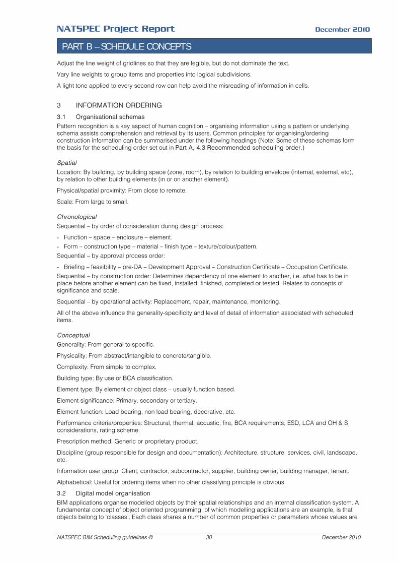
NATSPEC Project Report December 2010
PART B – SCHEDULE CONCEPTS
Adjust the line weight of gridlines so that they are legible, but do not dominate the text.
Vary line weights to group items and properties into logical subdivisions.
A light tone applied to every second row can help avoid the misreading of information in cells.
3 INFORMATION ORDERING
3.1 Organisational schemas
Pattern recognition is a key aspect of human cognition – organising information using a pattern or underlying schema assists comprehension and retrieval by its users. Common principles for organising/ordering construction information can be summarised under the following headings (Note: Some of these schemas form the basis for the scheduling order set out in Part A, 4.3 Recommended scheduling order.)
Spatial
Location: By building, by building space (zone, room), by relation to building envelope (internal, external, etc), by relation to other building elements (in or on another element).
Physical/spatial proximity: From close to remote.
Scale: From large to small.
Chronological
Sequential – by order of consideration during design process:
- Function – space – enclosure – element.
- Form – construction type – material – finish type – texture/colour/pattern.
Sequential – by approval process order:
- Briefing – feasibility – pre-DA – Development Approval – Construction Certificate – Occupation Certificate.
Sequential – by construction order: Determines dependency of one element to another, i.e. what has to be in place before another element can be fixed, installed, finished, completed or tested. Relates to concepts of significance and scale.
Sequential – by operational activity: Replacement, repair, maintenance, monitoring.
All of the above influence the generality-specificity and level of detail of information associated with scheduled items.
Conceptual
Generality: From general to specific.
Physicality: From abstract/intangible to concrete/tangible.
Complexity: From simple to complex.
Building type: By use or BCA classification.
Element type: By element or object class – usually function based.
Element significance: Primary, secondary or tertiary.
Element function: Load bearing, non load bearing, decorative, etc.
Performance criteria/properties: Structural, thermal, acoustic, fire, BCA requirements, ESD, LCA and OH & S considerations, rating scheme.
Prescription method: Generic or proprietary product.
Discipline (group responsible for design and documentation): Architecture, structure, services, civil, landscape, etc.
Information user group: Client, contractor, subcontractor, supplier, building owner, building manager, tenant.
Alphabetical: Useful for ordering items when no other classifying principle is obvious.
3.2 Digital model organisation
BIM applications organise modelled objects by their spatial relationships and an internal classification system. A fundamental concept of object oriented programming, of which modelling applications are an example, is that objects belong to ‘classes’. Each class shares a number of common properties or parameters whose values are
NATSPEC BIM Scheduling guidelines © 30 December 2010

NATSPEC Project Report December 2010
PART B – SCHEDULE CONCEPTS
varied to create a wide range of subtypes – producing ‘families’ or ‘libraries’ of parametric objects. This has the advantage that many common building elements can be modelled as variants of a few archetypes, instead of modelled every element from scratch.
This means BIM objects are already organised spatially and by a predefined classification system when a schedule is created from a modelling application – a door schedule is a report on all objects from the class ‘door’ located in the model. Ordering schedule properties by classification ordering principles fits well with the way modelling applications are organised.
4 USING SCHEDULES FOR DATA EXCHANGE
4.1 Schedules and BIM
Traditionally schedules have been reports or static summaries of information used largely for contract documentation purposes. Digital modelling applications allow schedules to be used in a much more dynamic way – for viewing the data content of a model in a format tailored to the needs of the user, and as a medium for two-way data exchange – data entered into them can be used to update the model.
If schedules are seen as windows into the information content of models, and as data entry interfaces, it opens up a whole range of potential uses not available to traditional paper-based schedules including:
- Briefing instruments to ensure requirements (client brief, BCA, GBCA rating schemes, etc) are incorporated in the design. Schedules can be used to report on the design’s compliance with these requirements – conditional formatting can alert the designer to non-compliant items. This use is not confined to passing briefing information from client to team or from one discipline to another. For example, someone can create a schedule that describes performance requirements for different building elements and pass it on to someone else in their office to insert specific proprietary products that satisfy these requirements. See examples of this approach in Part A, 5 Principles - protocols.
- Quality assurance documents such as project documentation templates, checklists and data entry control forms. The next two items are subclasses of these.
- Workflow management tools for project teams to co-ordinate the input and exchange of data, e.g. Model Progression Specifications which form the basis of contractual agreements such as the AIA Document E202-2008 BIM Protocol Exhibit. This document establishes the protocols for the development of the digital model over the duration of the project. It provides a means of documenting how authority and responsibility for the development of each model element is to be assigned to team members at each stage of the project.
- Templates for manufacturers creating digital objects of their products for downloading and incorporating in digital models. The template would include standardised parameters/properties, naming conventions, etc representing best practice as agreed by the construction industry.
4.2 Related articles
Bednick, J. (2008) Organising the Development of a Building Information Model.
Sidawi, R. (2010) BIM schedules: Information-rich resources.
NATSPEC BIM Scheduling guidelines © 31 December 2010

NATSPEC Project Report December 2010
REFERENCES
5 REFERENCES
AIA (Californian division) (2008) Integrated Project delivery.
AIA (2008) E202 BIM Protocol Exhibit – 2008.
AIQS (2003) Australian Cost Management Manual
Bednick, J. (2008) Organising the Development of a Building Information Model.
Sidawi, R. (2010) BIM schedules: Information-rich resources.
AS/NZS 1668.1:1998 The use of ventilation and airconditioning in buildings – Part 1: Fire and smoke control in multi-compartment buildings.
AS 4145.1-2008 Locksets and hardware for doors and windows – Part 1: Glossary of terms and rating system.
AS 4429-1999 Methods of test and rating requirements for smoke-spill fans.
SAA HB 50-2004 Glossary of Building Terms.
Building Code of Australia
ISO/IEC Guide 77-1:2008 Guide for specification of product properties and classes – Part 1: Technical principles and guidance.
ISO 12006-2: 2001 Organization of information about Construction Works – Part 2: Framework for Classification of Information.
NATSPEC BIM Scheduling guidelines © 32 December 2010

NATSPEC Project Report December 2010
APPENDIX A - PARENT LISTS OF PROPERTIES FOR SCHEDUES
APPENDIX A – PARENT LISTS OF PROPERTIES FOR SCHEDULES
1 PARENT PROPERTY LISTS
These lists were compiled from a number of existing door and door hardware schedules from a number of different sources. Where similar terms were used to describe the same property, the term aligned with the BCA or Australian standards, or the most representative of common industry usage, or the clearest was adopted. Terms have been grouped by item to assist reference. These lists are not exhaustive - there are endless types and variants of door hardware, for example.
1.1 Door schedule parent property list
Identification Viewing panels
Door number VP per leaf
Level VP size - rectangular: H x W
Room number VP size - circular: Diameter
Room name VP glazing bead type (HS or SP)
Location VP glazing bead material
VP glazing type
Structural opening VP glazing material
Structural opening height
Structural opening width Ventilation grilles
Wall thickness VG size H X W
Frame clearance - head VG type
Frame clearance - jambs VG model number
Head detail VG material
Jamb detail VG finish
Sill detail VG colour
Doorset details Door frame
Internal/external Overall door frame height
Single/pair/multiple Overall door frame width
Number of leafs Overall door frame depth
Functional description Door frame reveal width
Operation Door frame reveal height
Handing and swing Frame thickness
Leaf opens first Frame type
Door type Frame material
Fire resistance level Frame section
Acoustic rating Frame rebate depth
Radiation shielding Planted stop size H x W
Radio Frequency (RF) shielding Frame wall thickness
Escape width Transom section
Security rating Sill section
NATSPEC reference Frame detail
Frame finish
NATSPEC BIM Scheduling guidelines © 33 December 2010
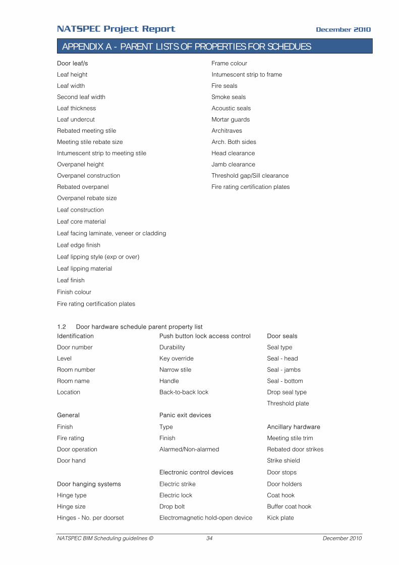
NATSPEC Project Report December 2010
APPENDIX A - PARENT LISTS OF PROPERTIES FOR SCHEDUES
Door leaf/s Frame colour
Leaf height Intumescent strip to frame
Leaf width Fire seals
Second leaf width Smoke seals
Leaf thickness Acoustic seals
Leaf undercut Mortar guards
Rebated meeting stile Architraves
Meeting stile rebate size Arch. Both sides
Intumescent strip to meeting stile Head clearance
Overpanel height Jamb clearance
Overpanel construction Threshold gap/Sill clearance
Rebated overpanel Fire rating certification plates
Overpanel rebate size
Leaf construction
Leaf core material
Leaf facing laminate, veneer or cladding
Leaf edge finish
Leaf lipping style (exp or over)
Leaf lipping material
Leaf finish
Finish colour
Fire rating certification plates
1.2 Door hardware schedule parent property list
Identification Push button lock access control Door seals
Door number Durability Seal type
Level Key override Seal - head
Room number Narrow stile Seal - jambs
Room name Handle Seal - bottom
Location Back-to-back lock Drop seal type
Threshold plate
General Panic exit devices
Finish Type Ancillary hardware
Fire rating Finish Meeting stile trim
Door operation Alarmed/Non-alarmed Rebated door strikes
Door hand Strike shield
Electronic control devices Door stops
Door hanging systems Electric strike Door holders
Hinge type Electric lock Coat hook
Hinge size Drop bolt Buffer coat hook
Hinges - No. per doorset Electromagnetic hold-open device Kick plate
NATSPEC BIM Scheduling guidelines © 34 December 2010
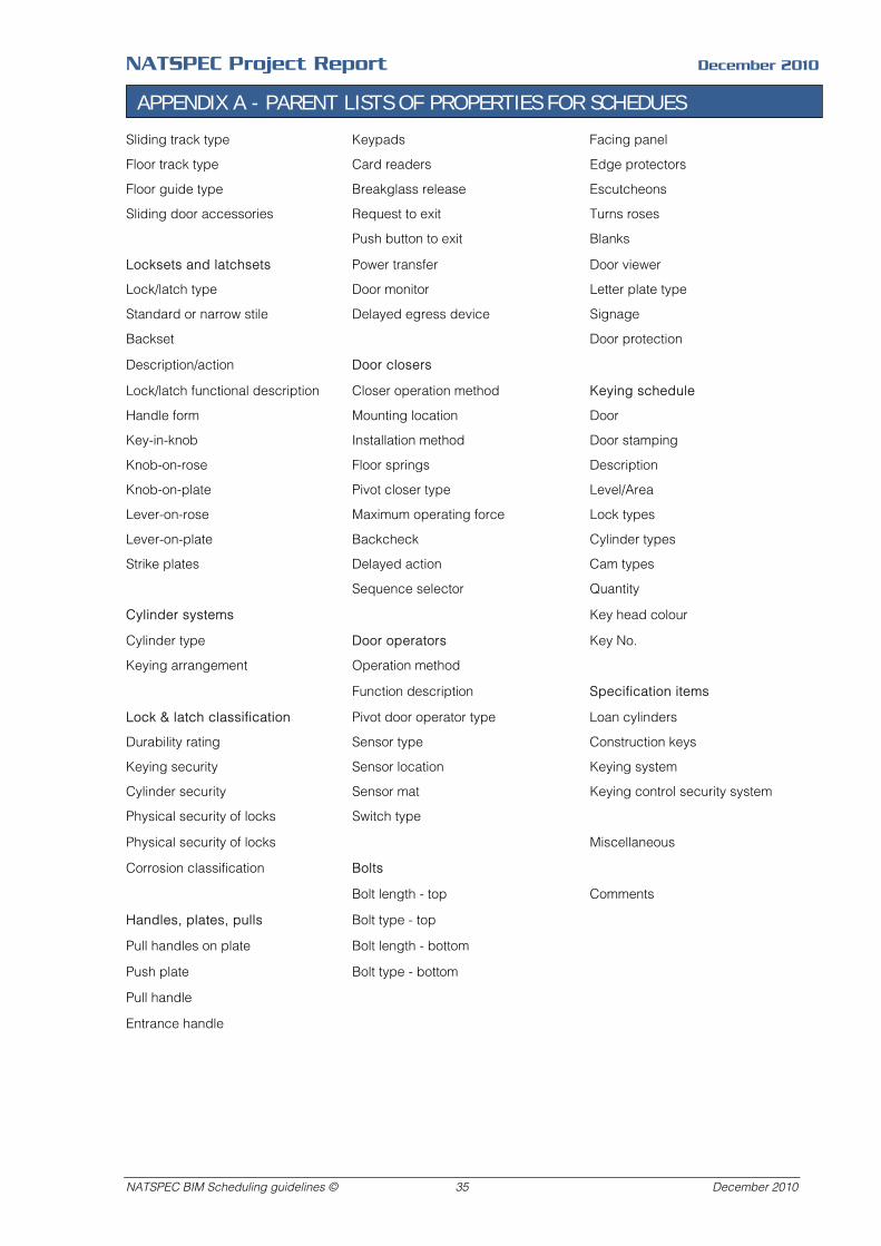
NATSPEC Project Report December 2010
APPENDIX A - PARENT LISTS OF PROPERTIES FOR SCHEDUES
Sliding track type Keypads Facing panel
Floor track type Card readers Edge protectors
Floor guide type Breakglass release Escutcheons
Sliding door accessories Request to exit Turns roses
Push button to exit Blanks
Locksets and latchsets Power transfer Door viewer
Lock/latch type Door monitor Letter plate type
Standard or narrow stile Delayed egress device Signage
Backset Door protection
Description/action Door closers
Lock/latch functional description Closer operation method Keying schedule
Handle form Mounting location Door
Key-in-knob Installation method Door stamping
Knob-on-rose Floor springs Description
Knob-on-plate Pivot closer type Level/Area
Lever-on-rose Maximum operating force Lock types
Lever-on-plate Backcheck Cylinder types
Strike plates Delayed action Cam types
Sequence selector Quantity
Cylinder systems Key head colour
Cylinder type Door operators Key No.
Keying arrangement Operation method
Function description Specification items
Lock & latch classification Pivot door operator type Loan cylinders
Durability rating Sensor type Construction keys
Keying security Sensor location Keying system
Cylinder security Sensor mat Keying control security system
Physical security of locks Switch type
Physical security of locks Miscellaneous
Corrosion classification Bolts
Bolt length - top Comments
Handles, plates, pulls Bolt type - top
Pull handles on plate Bolt length - bottom
Push plate Bolt type - bottom
Pull handle
Entrance handle
NATSPEC BIM Scheduling guidelines © 35 December 2010