Nationals Park - Pennsylvania State University · Final Architectural Engineering Senior Thesis...
67
Nationals Park 24 Potomac Ave SE, Washington DC 2003 Architectural Engineering Senior Thesis Matthew T. Moore Construction Management Spring 2008
Transcript of Nationals Park - Pennsylvania State University · Final Architectural Engineering Senior Thesis...
Nationals Park 24 Potomac Ave SE, Washington DC 2003
Architectural Engineering Senior Thesis
Matthew T. Moore Construction Management
Spring 2008

Final Architectural Engineering Senior Thesis Page 3
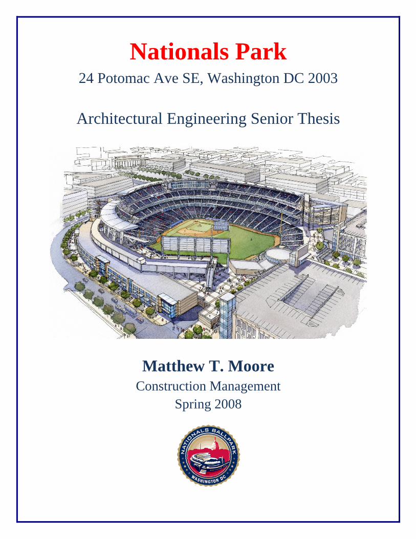
Architectural Engineer Senior Thesis Construction Management
Spring 2008
Table of Contents Page
Abstract................................................................................................................................2
Table of Contents.................................................................................................................3
Acknowledgements..............................................................................................................6
Executive Summary.............................................................................................................7
Project Overview.................................................................................................................8
Project Team........................................................................................................................9
Client Information..............................................................................................................10
Project Delivery System....................................................................................................11
Site Plan.............................................................................................................................12
Local Conditions................................................................................................................14 Waste Removal......................................................................................................14 Site Conditions – Geotechnical Report..................................................................14
Buildings System Summary...............................................................................................15 Demolition.............................................................................................................15 Support of Excavations..........................................................................................15
Structural Steel Framing........................................................................................16 Cast in Place Concrete...........................................................................................16 Precast Concrete....................................................................................................16 Masonry and Curtain Wall.....................................................................................16 Mechanical System................................................................................................17 Electrical System...................................................................................................17

Final Architectural Engineering Senior Thesis Page 4
Table of Contents Page
Project Schedule.................................................................................................................18 Key Project Dates..................................................................................................18 Foundation Sequence.............................................................................................19 Structural Steel Sequence......................................................................................20 Finishing Sequence................................................................................................21
Project Cost Evaluation......................................................................................................22 Overall Project Costs.............................................................................................22 D4 Cost..................................................................................................................22 R.S. Means.............................................................................................................22 Historical Comparison...........................................................................................22
Compare Estimates................................................................................................24
Short Interval Production Schedule – Research.................................................................25 Background............................................................................................................25 Problem Statement.................................................................................................26 Proposal..................................................................................................................26 Methodology..........................................................................................................26 Step 1 – Break the operation into specific activities..............................................27 Step 2 – Assign production rates to each activity..................................................28 Step 3 – Calculate extensions and set goals...........................................................29 Step 4 – Develop a time-scaled, resource loaded bar chart...................................29 Conclusion and Recommendation.........................................................................30
Structural Column Alternate Selection – Breadth Topic...................................................31
Background............................................................................................................31 Problem Statement.................................................................................................31 Proposal..................................................................................................................31 Applicable Design Codes.......................................................................................31 Structural Steel Design Codes...............................................................................32 Concrete Design Codes..........................................................................................32 Structural Steel Materials.......................................................................................32 Concrete Materials.................................................................................................32 Methodology .........................................................................................................33 Concrete to Steel Column Redesign......................................................................34 Cost Analysis.........................................................................................................35 Schedule Analysis..................................................................................................36 Conclusion and Recommendation.........................................................................37

Final Architectural Engineering Senior Thesis Page 5
Lighting Design – Breadth Topic......................................................................................38 Background............................................................................................................38 Problem Statement.................................................................................................38 Proposal..................................................................................................................38 Goal........................................................................................................................38 Old Lighting Fixture..............................................................................................38 Technical Information............................................................................................39 Current Lighting Design Images............................................................................40 New Lighting Fixture.............................................................................................41 Technical Information............................................................................................41 New Lighting Design Images................................................................................43 Cost Analysis.........................................................................................................44 Conclusion and Recommendation.........................................................................45
Appendix A – Site Plan......................................................................................................46
Appendix B – Project Schedule.........................................................................................48
Appendix C – Detailed Short Interval Production Schedule.............................................55
Appendix D – Concrete vs. Steel Cost Data......................................................................57
Appendix E – All Steel Structural Construction Schedule................................................63
Appendix F – Lighting Design Sheets...............................................................................65

Final Architectural Engineering Senior Thesis Page 6
Acknowledgements I would like to thank all of my family and friends who supported me in this year long
endeavor.
I would like to thank ISEC, Inc for all of their help and support.
I would like to thank the project team from Clark, Hunt, and Smoot.
I would also like to thank all of the Architectural Engineering Faculty.

Final Architectural Engineering Senior Thesis Page 7
Executive Summary Nationals Park is home to the Major League Baseball Team, The Washington Nationals.
The ballpark is a fast-tracked design build project located in the SE of Washington, DC.
The ballpark was completed by opening day for on March 30th, 2008. There are three
major general contractors that formed “A Joint Venture” and became Clark / Hunt /
Smoot, to oversee the ballparks construction. The ballpark was designed by another joint
venture, HOK Sport and Devrouax and Purnell. They were the architects that came
together to create the beautiful, and unique ballpark. The project has the largest
construction cost ever to date for a Major League Baseball stadium with an overall
project cost of $611 million.
The research that was done for this thesis is on Short Interval Production Scheduling,
(SIPS). Within this document you will find background on SIPS and well as the
methodology about how to develop a successful schedule. It describes that step by step
process which will guide you to developing a SIPS:
1. Break the operation into specific activities
2. Assign production rates to each activity
3. Calculate extensions and set goals
4. Develop a time-scaled, resource loaded bar chart
The first breadth area is on structural column redesign and how it can affect the project
schedule and the project budget. It shows how much a little change in the structural
redesign can change the project cost and project schedule.
The second breadth area is a lighting redesign of the indoor batting cages. It demonstrates
how by changing the lighting design you can save the owner building operation costs and
make the building more environmentally friendly.
Final Architectural Engineering Senior Thesis Page 8
Project Overview The Washington Nationals Ballpark is a fast-tracked design build baseball ballpark
located in the SE of Washington, DC. The ballpark is set to be completed by opening day
for Major League Baseballs Washington Nationals in April of 2008. Three major general
contractors in the DC area formed “A Joint Venture” to become Clark / Hunt / Smoot, to
oversee the ballparks erection. The ballpark is the creation of another joint venture in
HOK Sport and Devrouax and Purnell, the architects who came together to create the
beautiful, and unique ballpark. The project has the largest construction cost ever to date
for a Major League Baseball stadium with an overall project cost of $611 million.
Final Architectural Engineering Senior Thesis Page 9
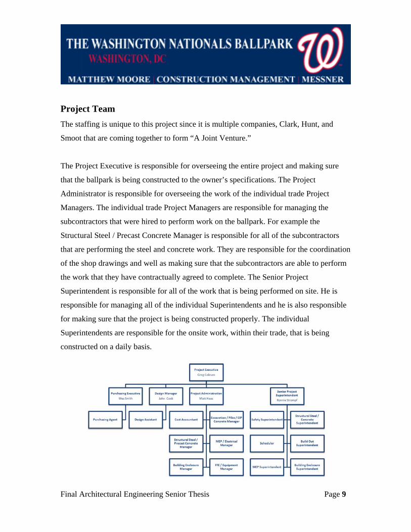
Project Team The staffing is unique to this project since it is multiple companies, Clark, Hunt, and
Smoot that are coming together to form “A Joint Venture.”
The Project Executive is responsible for overseeing the entire project and making sure
that the ballpark is being constructed to the owner’s specifications. The Project
Administrator is responsible for overseeing the work of the individual trade Project
Managers. The individual trade Project Managers are responsible for managing the
subcontractors that were hired to perform work on the ballpark. For example the
Structural Steel / Precast Concrete Manager is responsible for all of the subcontractors
that are performing the steel and concrete work. They are responsible for the coordination
of the shop drawings and well as making sure that the subcontractors are able to perform
the work that they have contractually agreed to complete. The Senior Project
Superintendent is responsible for all of the work that is being performed on site. He is
responsible for managing all of the individual Superintendents and he is also responsible
for making sure that the project is being constructed properly. The individual
Superintendents are responsible for the onsite work, within their trade, that is being
constructed on a daily basis.
Final Architectural Engineering Senior Thesis Page 10
Client Information The owner of the ballpark is the DC Sports and Entertainment Commission. They are
independent agency of the District of Columbia government. The DCSEC is active in the
planning and revitalization of the Anacostia water front. They are building the new
ballpark to help redevelop the area as well as to provide a new home for the Washington
Nationals, A Major League Baseball team. They will be responsible for the management
and operation of the new home to the Washington Nationals. The DCSEC wanted to
provide a spectacular venue for the Washington Nationals that will combine the best parts
of other MLB ballparks and well as provide its own unique style. As owners of the RFK
stadium, where the Nationals currently play, the DCSEC wanted to make sure that they
created a new ballpark that was above and beyond the old stadium, which can be seen
below in the stadium comparisons. They wanted the design of the playing field to have an
asymmetrical outfield to create exciting plays. They also wanted the make sure it had
great views from any seat in the house. One concern was how many seats it will hold
which it will have 41,222 outside seats and 76 suites, which includes 8 founder’s suites, 1
team owner double suite, 1 DCSEC double suite, 8 party double suites, and 58 regular
suites. The owner’s major concern with the project is that will it be ready for the start of
the 2008 baseball season, with the first pitch thrown on Sunday, March 30, 2008.
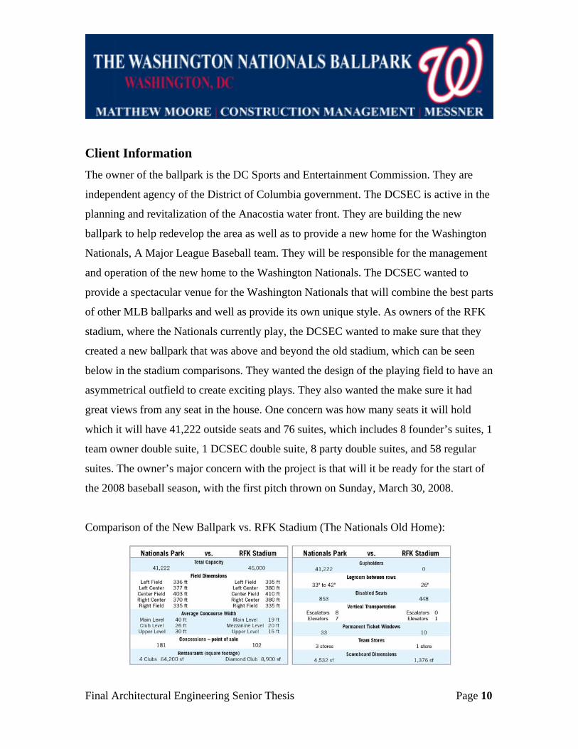
Comparison of the New Ballpark vs. RFK Stadium (The Nationals Old Home):

Final Architectural Engineering Senior Thesis Page 11
Project Delivery System The ballpark is an extremely unique project that has many different companies coming
together to form a joint venture to make the ballpark come to life. The project is a
combination of multiple companies coming together to deliver the fast-tracked design-
build project. The design team of HOK Sport, and Devrouax and Purnell, formed a joint
venture to act as the architects of the project. When they were 50% complete with the
design process, the Guaranteed Maximum Price (GMP) contract was accepted by the
District of Columbia. After the GMP contract was accepted, major local general
contractors, Clark, Hunt, and Smoot formed a joint venture to work together as one
construction company and perform the work as the construction managers on the
ballpark. They assumed the design team contract with the owner creating a large design
build firm. The major benefits of the design-build construction method are that it allows
for great coordination between the designers and the contractors. Coordination is a major
concern for making sure that project is completed on time for the 2008 baseball season.
Clark, Hunt, and Smoot, are in charge of holding the contracts between the GC and the
subcontractors.

Final Architectural Engineering Senior Thesis Page 12
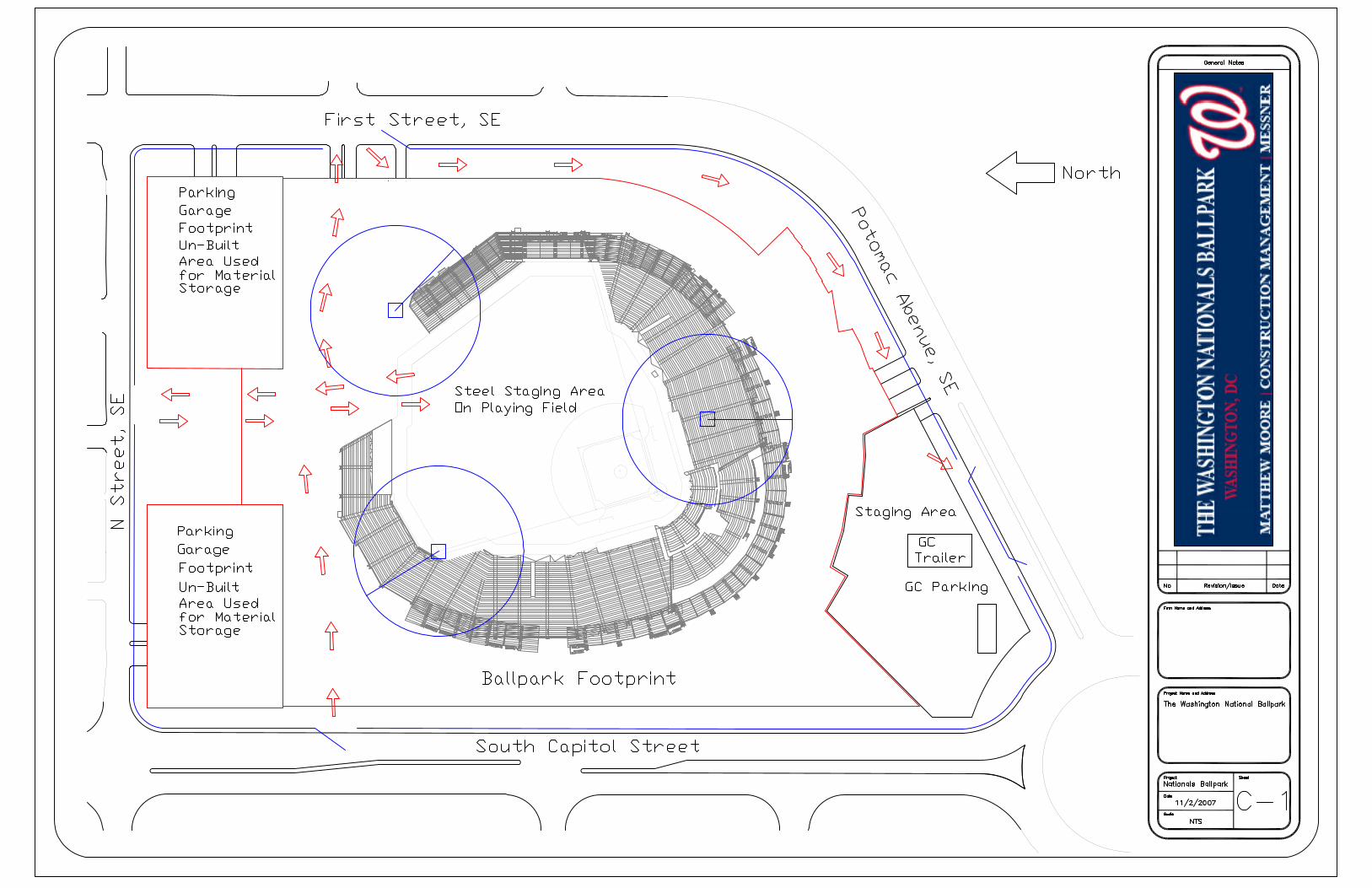
Site Plan The site is located in the middle of the revitalization of the “New Ballpark District.” The
ballpark is facing north and is on a direct line with The United States Capital. The
ballpark will have 2 parking garages and metro stop at the Navy Yard green line that is
one block from the ballpark. Below is a map of Washington, DC showing the close
proximity of the ballpark to the National Mall.
Map of Washington, DC:
National Mall
Ballpark Site

Final Architectural Engineering Senior Thesis Page 13
The ballpark has a very unique site layout due to the constraints on being located in the
heart of the “New Ballpark District” in Washington, D.C. The site layout which is located
in Appendix A is for the initial stage of steel erection before the construction of the 2
parking garages, which will be located on the site right next to the ballpark. The position
of parking garages were initially used for material lay down, until their construction is to
commence. The center of the playing field was the location for all of the steel lay down
area. The steel will need to be fully erected before the construction of the playing field’s
surface can begin. A major concern with the site plan is that once the stadium is fully
erected there will be very few spaces that can be used as material lay down areas. With
the limited space that will be created, it will in then in turn create major scheduling issues
that dictate when materials can be delivered. It will only allow the material that is
absolutely necessary for that weeks work to be able to be delivered to the site so it can be
installed right away and not take up any room on the already congested site. There are
also 3 cranes operating at the same time to help shorten the time for the building
superstructure to go up.

Final Architectural Engineering Senior Thesis Page 14
Local Conditions
Waste Removal
The overall goal of the waste removal program is that by the end of the project there will
be a minimum of 75% salvage and recycling ratio vs. the total wasted generated by the
work. There will be separate containers for recyclable materials and every worker is
required to be trained on proper waste management.
Site Conditions - Geotechnical Report
The proposed ballpark structure will have concrete framing which will then support a
steel frame. The design loads are from approximately 200 kips to 3600 kips. There were
19 test boring taken in 2 different phases. In phase 1, 6 test borings were initially taken
and then in Phase 2, 13 test borings were taken. The site is underlain with loose/soft fill
consisting of silt, fat clay and silty sand, with asphalt, concrete and brick fragments down
to 25 feet below the surface. The next level of soils consist of alluvium and terrace
deposits containing inter-bedded deposits of medium stiff to hard fat clay, very soft to
hard lean clay and sandy silt, and dense to very dense clayey sand to poorly graded gravel
down to 72 feet. They are then followed by stiff to hard sandy lean clay to fat clay and
dense to very dense poorly graded sand with clay to clayey sand down to 100 feet. The
allowable bearing capacity of 3000 psf is to be located on natural soils and on the sand
filters they can carry a capacity up to 2000 psf. The recommendation for the foundations
is that it is to be a deep foundation system with the use of 14 inch steel H-piles. The
backfill is to consist of SM, SP, SW, GM, GC, GP or GW soils per ASTM D-2487 with a
liquid limit of 45 and plasticity index of 15. The fill that is placed behind a retaining wall
should be compacted to 95% of the max dry density as per ASTM D-698.

Final Architectural Engineering Senior Thesis Page 15
Building Systems Summary
Work Scope Yes No
Demolition Required X
Support of Excavation X
Structural Steel Frame X
Cast in Place Concrete X
Precast Concrete X
Masonry and Curtain Wall X
Mechanical System X
Electrical System X
Demolition
It was necessary for the demolition of buildings located on site before the construction
could begin. The ballpark is located in the South East of Washington, DC, where they are
trying to revitalize the area around the ballpark. The entire surrounding areas are all
going to be demolished and rebuilt in hopes that it will renew the area. It is effectively
named “The Ballpark District” which is going to be a mixed use community that features
shops, restaurants, entertainment venues, offices, hotels, and apartments.
Support of Excavation
A free draining sheeting systems, which consists of H Beams, wood lagging and bracing,
was used for excavation support. All excavations were within code from the
Occupational Safety and Health Administration (OSHA) and in accordance with the
District of Columbia and Federals regulations for supporting the excavation.

Final Architectural Engineering Senior Thesis Page 16
Structural Steel Framing
The structural steel is unique because it is only located in the structures above the Club
Level as well as in the scoreboard in the right field. All of the rolled shapes excluding
angles and channels shall conform to ASTM A992 or A572, Grade 50 steel. The
connection materials are conformed to ASTM A36 steel. The metal decking is composed
of 3” 18 gage type VL.
Cast in Place Concrete
Cast in place concrete is used for the foundation and SOG. The SOG is 6” thick with
reinforced WWF which is on top of a drainage layer made of washed gravel and crushed
stone. There are also foundation walls on the services level that are cast in place concrete,
which are to be 18” thick min. The retaining walls on the service level are 24” min to
support the backfill pressure. They are all vertically formed by formwork and are
required to have a design strength of 5000 psi after 28 days.
Precast Concrete
Precast concrete is mainly used for the seating bowl of the stadium. They are precast, pre-
stressed with 6” thick risers and 4” thick treads that are formed offsite. The precast
seating will have an average thickness of 5.5” and are reinforced to 1.5 psf.
Masonry and Curtain Wall
The ballpark consists of pre-cast concrete with masonry back-up curtain wall and
storefront glazing systems, as well as metal panels with masonry back-up. There are
single wythe running bond CMU with rebar that are filled cell for support. The roofing
systems are made up of a combination of many types including a parapeted built-up roof
with scupper and leader drainage, and some sheet metal decking with scupper and leader
drainage.

Final Architectural Engineering Senior Thesis Page 17
Mechanical System
The mechanical system is designed for a peak cooling load of 2000 tons. It has (2) 800
ton water cooled chillers for the on peak loads and (1) 400 ton water cooled chiller for the
off peak loads. The cooling loads were designed with an outside temperature of 95o F dB
and 76 o F Wb, and with an inside temperature of 72 o F +/- 3 o F. Humidity will not be
added to any of the enclosed spaces and it will be kept under 60% at all times. The
premium spaces will have variable air volume air handling units with VAV Boxes for
control. For the heating loads there will be (2) 12500 AMBH output, natural gas fired,
forced draft hot water boilers.
Electrical System
The electrical system has (3) 13.2 kV circuit feeders that are provided from the Potomac
Electric Power Company (PEPCO) that will supply the ballpark. The main switchgear
feeds the step-down transformers that support a 4160 volt network bus switchgear that
are distributed throughout the ballpark. There are unit substations have dry type
transformers rated for 28500/3330 kVA, 4, 160 volt, 3-phase delta primary and a 480/277
volt wye secondary. The transformers feed a 400 amp switch board rated for 277/480
volt, 3 phase, 4-wire. There is also an emergency power system that has generators that
will provide 1000 kW and 1250kW in the case of a power failure. The generators will
provide back up for the building egress lighting, seating bowl emergency lighting, fire
alarm systems, security systems, fire department communication, emergency sound
system and fire pump systems.

Final Architectural Engineering Senior Thesis Page 18
Project Schedule The detailed project schedule that highlights the major phases of construction, with an
emphasis on the foundation and structure for the ballpark can be found in Appendix B.
The ballpark is being created with the most intensive schedule ever created for a Major
League Ballpark. It is schedule to only take 2 years to complete, which has never been
done before. Because of the hard deadline of opening day the schedule for the ballpark
schedule was developed with very little margin for error in construction.
There is a fee of $1,000,000 per day in liquated damages if the ballpark is not completed
by opening day for The Washington Nationals.
Key Project Dates
• Schematic Design Begins September 6, 2005
• Notice to Proceed March 22, 2006
• Foundations Started May 22, 2006
• CIP Concrete Begins June 14, 2006
• Structural Steel Started October 5, 2006
• Topping Out July 11, 2007
• Playing Field Begins October 1, 2007
• Substantial Completion March 21, 2008
• First Pitch March 30, 2008

Final Architectural Engineering Senior Thesis Page 19
Foundation Sequence
The ballpark consists of a deep foundation system. They are using 14” concrete H-piles
which were driven down 45 feet to gain the allowable bearing capacity of 100 tons per
pile. They were left 2’6” above the slab-on-grade so that the structure can tie into the
foundation system. The foundation system was selected due to the site containing very
hard clays and silty sands, which is typical since it is located right along the Anacostia
River. The foundation was sequenced by breaking the ballpark into 10 different areas,
which can be seen in the plan below. There were 3 different rigs which drilled an average
of 12 piles per day. The first rig started in Area 1 and continued to Area 2. (See
Construction Area Breakdown to note the location of the different areas) The second rig
started in Area 4 and moved to Area 3 and then Area 5. The third rig was started in Area
7 and moved to Area 8 and then to Area 10. This was sequenced by making sure the main
concourse area was completed first because that is where the majority of the ballparks
structure is. The rigs worked their way around to meet in between Area 2 and Area 3,
which is the center of the main concourse area.

Final Architectural Engineering Senior Thesis Page 20
Construction Area Breakdown:
Structural Sequence
The structural sequence is unique because half way through construction it was changed
from a concrete structural system to a steel structural system, due to fact that steel was a
long lead time item and concrete would allow them to fast-track the project and begin
while the steel was being fabricated. The concrete framed areas, the 1st and 2nd level, are
cast in place beams and girders. The 3rd level and above will be steel construction. The
structural steel is sequenced the same way that the foundation was. They first starting
erecting in Area 1 and continued to Area 2. They then started in Area 4 which was
followed by Area 3 and then Area 5. They then erected the steel in Area 7, and then Area
8.

Final Architectural Engineering Senior Thesis Page 21
Finishing Sequence The finishing work that must be completed is located inside premium spaces in the
ballpark, which includes rooms like the Players Locker Rooms, the Founders Bar and the
many Suites. The interior build out sequence is broken down by:
• GWB Framing
• Tie-in Conduit/Pull Wire
• Hang GWB Walls
• Paint Walls
• Acoustic Ceiling Grid
• GWB Ceiling Framing
• GWB Ceilings
• Light Fixtures and MEP Drops
• Millwork
• Plumbing Fixtures
• Flooring
• Doors and Architectural Trim
• Toilet Accessories
• Finish Painting and Wall Covering
• Ceiling Pads
• MEP Devices
• FF & E

Final Architectural Engineering Senior Thesis Page 22
Project Cost Evaluation
Overall Project Costs
The overall project cost for the ballpark is $611 million.
The cost per square foot (611 million / 1.2 million square feet) is $509.16 per square foot.
D4Cost
D4Cost was used to try to create a schematic estimate of the ballpark. D4Cost uses actual
cost data from existing building projects to help develop a schematic estimate of a new
construction project. Unfortunately there is only 1 related project which the ballpark can
be compared to, the Southwestern Bell Bricktown Ballpark, a minor league (AAA)
stadium with an overall project cost of $21,835,787. With the location modifier of
Washington, DC and an updated time modifier, D4Cost came up with an overall
construction cost of $177,191,520. It is well below the ballparks overall project cost.
R.S. Means
There is no way to estimate a baseball stadium by a square foot estimate in R.S. Means.
Historical data on ballpark construction costs were compared instead.
Historical Data Comparison
Typically ballpark estimates are based off of cost per seat, therefore project cost and
seating capacity was collected from the 10 the most recent major league ballparks that
have been constructed.

Final Architectural Engineering Senior Thesis Page 23
Cost Comparisons of Recent Ballpark Construction:
Team Ballpark Name Year Project Cost
(millions) Capacity Cost / Seat
Washington
Nationals
Washington National
Ballpark 2008 $611 41222 $14,822.18
St. Louis
Cardinals Busch Stadium 2006 $346 43975 $7,868.11
Philadelphia
Phillies Citizens Bank Park 2004 $346 43647 $7,927.23
San Diego
Padres PETCO Park 2004 $411 42445 $9,683.12
Cincinnati
Reds
Great American
Ballpark 2003 $297 42059 $7,061.51
Milwaukee
Brewers Miller Park 2001 $322 42200 $7,630.33
Pittsburgh
Pirates PNC Park 2001 $230 38496 $5,974.65
Detroit
Tigers Comerica Park 2000 $300 41070 $7,304.60
Houston
Astros Minute Maid Park 2000 $266 40950 $6,495.73
San Francisco
Giants AT&T Park 2000 $306 41503 $7,372.96
Seattle
Mariners Safeco Field 1999 $517 47116 $10,972.92

Final Architectural Engineering Senior Thesis Page 24
Compare Estimates The Washington National Ballpark has the largest project cost in the history of
construction of Major League Baseball stadiums. This can be contributed to the excessive
amount of luxury boxes, 78 in total, as well as the fast-tracked schedule. The ballpark is
trying to become the first LEED rated stadium. There are also major cost impacts from
the extreme fast paced schedule that they needed to create to make sure the ballpark
opened on time. It is also extremely expensive in trying to achieve the LEED rating. The
D4Cost estimate can not even compare to the overall budget of the project because it is
based off of historical data from a Minor League ballpark which will not have any of the
same amenities that a Major League ballpark has.

Final Architectural Engineering Senior Thesis Page 25
Short Interval Production Schedule – Research
Background
Nationals Park has multiple highly repeatable tasks that can be scheduled as efficiently as
possible by the development of a Short Interval Production Schedule (SIPS). SIPS is a
highly detailed way to schedule a repetitive construction project. Many construction
projects go over budget and over schedule due to poor detailed scheduling and with the
use of a SIPS it can make sure the project gets completed on time and on budget.
A SIPS is developed to detail the necessary day-to-day production or task-to-task
production during any repeatable construction project. It details scheduling at the crew
level and must rely on exact information that is vital to the successful completion of any
construction task. The most usefully cases where a SIPS can be beneficial is for a project
that has many highly repeatable activities, such as apartments, hotels, office buildings
and even schools. Typically, these projects will have a standardized interior floor or wing
layout that makes the use of a SIPS desirable. The ballpark has just that with 58 of the
same exact luxury suite. The interior build out of the suites will gain a great deal of
scheduling time if SIPS was used to construct the luxury suites.
There are 3 main ideas that differentiate SIPS from any other standard scheduling
methods:
• Only one major specific operation is detailed
• A higher level of detail is developed then typically seen
• There must be personnel involvement and commitment from everyone
contributing to the operation

Final Architectural Engineering Senior Thesis Page 26
There are 5 steps that need to be taken to develop a SIPS:
1. Break the operation into specific activities
2. Assign production rates to each activity
3. Calculate extensions and set goals
4. Develop a time-scaled, resource loaded bar chart
The major benefits that will be seen throughout the project will only be achieved if every
participant involved had at least a general understanding of the SIPS that will be utilized.
The superintendents and the subcontractors must have firsthand knowledge of the minor
details that will go into the construction of the building. The crew members must be
given a very detailed schedule of the general building sequencing and time period the
tasks needs to be completed before the job can even begin.
Burkhart, A. (1989). "The use of SIPS as a productivity improvement tool." Construction
Congress 1989, Concrete Construction Publications, Inc. 381-386.
Problem Statement
Due to the repeatability of the 58 luxury suites, how can the use of a Short Interval
Production Schedule benefit the completion of the ballpark?
Proposal
The development of a SIPS will have major time implications if it is properly designed
and executed for the interior build out for the 58 luxury suites.
Methodology
There are 5 steps that need to be taken to develop a SIPS (Burkhart):
1. Break the operation into specific activities
2. Assign production rates to each activity

Final Architectural Engineering Senior Thesis Page 27
3. Calculate extensions and set goals
4. Develop a time-scaled, resource loaded bar chart
Step 1 – Break the operation into specific activities
The first step is to break the selected tasks into a list of activities that will be necessary to
complete all of the work at hand. One great way to come up with activities is by sitting
down with the all of the supervisors and have a brainstorming session about the order of
tasks. This is the finishing sequence of the 58 luxury suites that was developed.
• Subroof
• GWB Framing
• Tie-in Conduit/Pull Wire
• Hang GWB Walls
• Paint Walls
• Acoustic Ceiling Grid
• GWB Ceiling Framing
• GWB Ceilings
• Light Fixtures and MEP Drops
• Millwork
• Plumbing Fixtures
• Flooring
• Doors and Architectural Trim
• Toilet Accessories
• Finish Painting and Wall Covering
• Ceiling Pads
• MEP Devices
• FF & E

Final Architectural Engineering Senior Thesis Page 28
Step 2 – Assign production rates to each activity
Assigning the right production rate to each activity is the most important and difficult
step to complete properly. As seen on the this page, each task is broken into manageable
groups and each production rate is assigned to each individual activity. Grouping of the
activities was necessary to make sure each task would fit well into allotted time constraint
of a 2 day activity group.
Production Rates
ID Interior Buildout
# days to complete
10 Suites
# of days to
complete 1 suite
# of suites completed
per day
Subroof 5 0.5 2 1 GWB Framing 15 1.5 0.666667
Suite Exterior Slider System 15 1.5 0.666667 2 Tie-in Conduit/Pull Wire 5 0.5 2
Hang GWB Walls 10 1 1 Paint Walls 5 0.5 2 3
Acoustic Ceiling Grid 5 0.5 2 GWB Ceiling Framing 5 0.5 2
GWB Ceilings 5 0.5 2 4 Light Fixtures and MEP Drops 10 1 1
Millwork 15 1.5 0.666667 5 Plumbing Fixtures 5 0.5 2
Flooring 10 1 1 Doors and Architectural Trim 5 0.5 2 6
Toilet Accessories 5 0.5 2 Finish Painting and Wall Covering 5 0.5 2
Ceiling Pads 5 0.5 2 MEP Devices 5 0.5 2
7
FF & E 5 0.5 2

Final Architectural Engineering Senior Thesis Page 29
Step 3 – Calculate extensions and set goals
This is the step were you try to figure out any setbacks that might occur throughout the
construction of the suites. Because this is being done in the beginning of the suites
scheduling process there are no unforeseen setbacks currently. It is important however to
brainstorm any unanticipated incidents because it can help serve as a guideline giving
you ideas about what to look out for during the installation process.
Step 5 – Develop a time-scaled, resource loaded bar chart
This is the last step in the development of a SIPS. This is where you take all of the
information that you have gathered in the previous steps and combine it to create your
Short Interval Production Schedule. Below is a sample of the SIPS that was developed
for the interior suites build out. The more detail and complete schedule can be found in
appendix C.

Final Architectural Engineering Senior Thesis Page 30
Conclusion and Recommendation
After the development of the SIPS for the interior suites it was discovered that it will only
take the suites a total of 123 days to complete the interior build out. The project schedule
gave the suites 157 days to complete the entire suites. That is a saving of 34 important
days that can be saved due to the repeatability of the suites as well as the very detailed
scheduling that occurred. Since many construction projects go over budget and over
schedule due to poor detailed scheduling and SIPS will not only help keep it on schedule
it can also help reduce the overall time that a activity can take due to the high level of
detail and repetition that can occur.

Final Architectural Engineering Senior Thesis Page 31
Structural Column Alternate Selection – Breadth Topic
Background
The ballpark is a combination of steel and cast in place concrete. The structural steel is
unique because it is only located in the structures above the Club Level as well as in the
scoreboard in the right field. Cast in place concrete was used for the load bearing
columns for the Service Level (1st level only). Washington DC is known for there CIP
concrete structural systems but steel is starting to take over.
Problem Statement
A cast-in-place (CIP) concrete structural system takes much more construction time to
erect then a steel structural system. Would it save valuable schedule time and be more
cost effective if the ballpark was designed using only one type of structural system,
specifically an all steel system?
Proposal
Changing all of the structural CIP concrete columns to steel equivalent would help save
valuable construction time and help shorten the overall project schedule. The goal is to
get the ballpark built as quickly as possible without any extreme added cost. This will
look at the benefits and trade offs that will deal with the use of all one structural system.
It will specifically look at the cost impact and the project schedule impact that the one
structural system will effect.
Applicable Design Codes
All structural elements shall be designed in accordance with the requirements of the
International Building Code 2000, as amended by the District of Columbia Register, 2003

Final Architectural Engineering Senior Thesis Page 32
Structural Steel Design Codes
All structural steel shall be designed in accordance with the IBC 2000. In general, details
and design of structural steel shall be in accordance with the American Institute of Steel
Construction, “Manual of Steel Construction, Load and Resistance Factor Design”, 3rd
edition.
Concrete Design Codes
All concrete structures shall be designed in accordance with the IBC 2000. Ultimate
strength design shall be used in accordance with ACI-318-02, “American Concrete
Institute, Building Code for Structural Concrete.” In general, details shall be in
accordance with ACI 315, “Manual of Standard Practice for Detailing Reinforced
Concrete Structures,” latest edition.
Structural Steel Materials
• All rolled shapes excluding angles and channels shall conform of ASTM A992 or
A572, Grade 50
• All connection material and base plates shall conform to ASTM A36
• All angles and channels shall conform to ASTM A36
• All anchor bolts shall conform to ASTM F1554, unless otherwise noted on
drawings
• All bolts other than anchor bolts shall conform to A325 or A490
Concrete Materials
• All concrete shall have the indicated design strength after 28 days
o Footings and Slab On Grade 4000 psi N.W.
o Foundation 4000 psi N.W.

Final Architectural Engineering Senior Thesis Page 33
o Slab on Metal Deck 4000 psi N.W.
o Cast In Place Reinforced Slabs 5000 psi N.W.
o Cast In Place Reinforced Columns 5000 psi N.W. min
o Topping slabs 3000 psi N.W.
• All reinforcing bars shall be ASTM A615, Grade 60 deformed bars
o Yield strength may not exceed 78 ksi
o Ratio of actual ultimate tensile strength to the actual tensile yield strength
may not be less than 1.25
• All stirrups and column ties shall be deformed bars with 60,000 psi minimum
yield strength, ASTM A615, Grade 60
• All reinforcing to be welded shall be ASTM A706, Grade 60
Methodology
The existing structural system was reviewed and it was discovered that only the 1st level
was selected to be cast-in-place concrete. This was found to be unusual because
everything else was designed using an all steel framing system.
A typical bay was selected for the redesign of the structural columns and it was located
between the column line 33 and the column line 38, which can be seen on the next page.
There are 5 other similar typical bays that were extrapolated to get the overall steel cost.

Final Architectural Engineering Senior Thesis Page 34
Service Area structural floor plan from column line 33 to 38 highlighted in red:
Concrete to Steel Column Redesign
The goal is to determine the least weight column that can handle the already factored
load. The design is done by using LRFD.
The typical column that was selected is on line 36 and is a 36” x 48” concrete column,
12#11 rebar with an effective height of 20 ft. The applied load is 1000 kips and is already
factored (done by structural designer). The cost for that concrete column is $6,422.22
The effective length for each axis was assumed to be the same in both directions
KLy = 20 ft
KLx = 20 ft

Final Architectural Engineering Senior Thesis Page 35
Since the column has the same effective length about the x-axes and y-axes it was
concluded that KL=20 ft.
The Steel Construction Manual was used to find the least weight W member that can
carry the applied already factor load of 1000 kips.
The member that can carry the applied load is a W12 x 120 which can carry a applied
load of 1030 kips.
The cost was then analyzed and it was found that the cost of the new steel column is
$4,560.00 which is based off the member size and weight.
Cost Analysis
The cost data was taken from RS Means Building Construction Cost Data 2008 and it
included all material and labor for the steel and for the concrete estimate the rebar was
included, as well. A more detailed breakdown of the individual estimates can be found in
Appendix D.
The comparison of overall cost differences can be found on the next page in the Concrete
vs. Steel Column Summary table. The overall cost of using all steel structural columns
instead of a combined system showed an increase in the construction cost of over
$1,659,392.64. That is a major increase in the overall project cost just by selecting the
alternate columns.

Final Architectural Engineering Senior Thesis Page 36
CONCRETE vs. STEEL COLUMNS SUMMARY
SUBTOTAL STEEL TYPICAL SECTION ESTIMATE: $532,976.60 LOCATION MULTIPLIER 99% FOR DC: $527,646.83
TOTAL STEEL TYPICAL SECTION COST: $527,646.83 SUBTOTAL CONCRETE TYPICAL SECTION ESTIMATE: $253,617.57
LOCATION MULTIPLIER 99% FOR DC: $251,081.39 TOTAL CONCRETE TYPICAL SECTION COST: $251,081.39
INCREASE IN COST DUE TO ALL STEEL TYPICAL
SECTION: $276,565.44
SUBTOTAL COMPLETE STEEL ESTIMATE: $3,197,859.60
LOCATION MULTIPLIER 99% FOR DC: $3,165,881.00TOTAL STEEL COST: $3,165,881.00
SUBTOTAL CONCRETE ESTIMATE: $1,521,705.42
LOCATION MULTIPLIER 99% FOR DC: $1,506,488.36TOTAL CONCRETE COST: $1,506,488.36
INCREASE IN COST DUE TO ALL STEEL: $1,659,392.64
Schedule Analysis
The new construction schedule for the column redesign can be found in Appendix E. In
the dual system that the design team selected it was expected to take 140 days to
construct the 1st level concrete columns. It was found that it would only take 60 days to
construct the same amount of columns for the structural steel system. By switching the
concrete columns to steel columns it would save the construction team almost 80 days as
long as there are no major setbacks.
Final Architectural Engineering Senior Thesis Page 37
Conclusion and Recommendation
Overall there are two major conclusions that can be made from this analysis of an
alternate column system. The 1st conclusion to be made is that it is not beneficial to the
overall project budget if it was designed using only steel columns. An increase in over $1
million can not be an acceptable outcome to the owner of the building. The 2nd
conclusion is that it does help shorten project schedule time and could very well impact
the overall project schedule. It could help the project team gain 80 days as long as there
are no major setbacks.
It comes down to what is driving the project more, cost or schedule. Since schedule is the
most important factor in driving the ballpark project it is acceptable to use an all steel
structural system. With $1 million per day in liquated damages for every day that The
Washington Nationals can’t occupy the ballpark it would make it seem like the schedule
is what is driving this project.

Final Architectural Engineering Senior Thesis Page 38
Lighting Design for Indoor Batting Cage - Breadth
Background
The current lighting design for indoor batting cage located within the ballpark is currently
based off of gym criteria. The room is expected to have an illumance of 50 fc. which can
be done with a multiple of different options for lamp types, like metal halide lamps and
fluorescent lamps. Lighting designers are still using Metal Halide lamps in there lighting
design even when there are better products out there. Metal halide lamps have to warm up
before they light up and other options such as a 4100K fluorescent lamps light up
instantly when the light switch is flipped.
Problem Statement
Is there an alternative lighting solution that can activate instantly without have to warm
up and help reduce the electricity cost?
Proposal
By selecting an alternate lighting system for the indoor batting cage there will be a way to
reduce the overall power use and help reduce the total building electricity load.
Goal
The goal is to find a better choice for a lighting system that will not only provide
adequate lighting conditions but will also help reduce the load on the power system.
Old Lighting Fixture
The old lighting fixture was a TX A26: Premium Enclosed Aluminum Optical made by
Lithuania. The lamp is a 400-Watt Clear BT-37 Metal Halide.

Final Architectural Engineering Senior Thesis Page 39
Technical Information
Intended Use
• Areas that require good vertical illumination
• Excellent glare control at low mounting heights
• Ideal for general open areas, retail spaces, aisles and manufacturing areas
Ballast
• High power factor ballast with a minimum of class H insulation.
Optics
• Injection-molded virgin acrylic lens, fully fluted anodized aluminum reflector
• Hinge and lens retainer latches facilitate tool-less removal for maintenance and
cleaning
• Totally enclosed, gasketed refractor and reflector inhibit the entrance of ambient
contaminants.
Socket
• Glazed porcelain, vertically oriented, mogul-base socket with copper alloy,
nickel-plated screw shell and center contact
• UL Listed 1500W, 600V
• 4KV pulse-rated

Final Architectural Engineering Senior Thesis Page 40
Current Lighting Design Images

Final Architectural Engineering Senior Thesis Page 41
New Lighting Fixture
The new lighting fixture that was selected for the indoor batting cages is a Schelde Sports
Light 54 with 4 high output T5 4100K fluorescent lamps.
.
Technical Information
SportLight 54
IFT5 Four-Lamp
Product Features
• Ideal solution for high mounting applications
• Excellent alternative to costly HID fixtures
• T5 high output 4100K fluorescent lamps
• Energy efficient high power factor electronic ballasts
• Reduced energy cost by 50%
• 96% specular reflector
• Proprietary modular reflector
• Lightweight corrosion resistant aluminum alloy housing

Final Architectural Engineering Senior Thesis Page 42
• Shipped fully assembled
• Easy to install
Electrical Information
• Thermally protected, Class "P", HPF, sound rated, electronic ballast
Rotary lock lampholders
• Total system wattage 246
• Universal voltage for 120V through 480V UL/CUL listed
Lamp
• Four high output T5 4100K fluorescent lamps
• Color rendering index 85
• Mean lumen output (fixture) 16,734
• Lamp lumen maintenance up to 94%
Construction
• .040" aluminum die formed housing and end plates
• End plates are fastened to frame with screws
• Quick release access covers allow accessibility to ballast while fixture is still
hanging
• Fixture weight 10 pounds

Final Architectural Engineering Senior Thesis Page 43
New Lighting Design Images

Final Architectural Engineering Senior Thesis Page 44
Cost Analysis
The SportLight 54’s T5 4100K fluorescent lamps cost half as much as the Metal Halide
Lamp. Overall the owner, The DCSEC could save up to $1,458.72 per year in operational
costs.
Lighting Comparison
400/U Metal Halide vs. SportLight 54
Lighting Type Initial Lumens Mean Lumens
Lamp Life
(Hours)
Total Wattage/ Fixture
Enegry Cost / Fixture / Year
@ $0.11/KWH
400/U Metal Halide 36,000 23,500 20,000 458 $440.12
SportLight 54 17,800 16,734 24,000 246 $236.40 (6) Metal Halide Yearly Cost $2,640.72 (5) SportLight 54 $1,182.00 Savings by using SportLight 54 $1,458.72

Final Architectural Engineering Senior Thesis Page 45
Conclusion and Recommendation
There are many benefits from the redesign of the indoor batting cage lighting system. By
switching to a florescent lamp from a metal halide lamp you not only saved the owner,
The DCSEC up to $1,458.72 per year in operational cost, it improved the overall lighting
situation for the Nationals. The will not have to wait for the lights to warm up and have a
slow start up. They will also benefit from the better lighting conditions while taking
batting practice. It was demonstrated that by changing the lighting design you can save
the owner building operation costs and make the building more environmentally friendly.
Final Architectural Engineering Senior Thesis Page 46
Appendix A Site Plan

Final Architectural Engineering Senior Thesis Page 48
Appendix B Project Schedule

Activity ID Activity Name Start Finish OriginalDuration
The WashiThe Washington Nationals Ballpark 06-Sep-05 A 14-Apr-08 672
Pre-ConsPre-Construction Phase 06-Sep-05 20-Jun-07 456
A1000 Schematic Design Documents 06-Sep-05 25-May-07 438A1010 Precurement of Subcontractors 06-Sep-05 25-May-07 438A1020 Design Assist 20-Mar-06 25-Apr-07 281A1280 Submittals 10-Apr-06 25-May-07 288A1290 Bid and Purchase 27-Jun-06 20-Jun-07 251
ConstrucConstruction Phase 22-Mar-06 A 14-Apr-08 535
MobilizatMobilization and Site Work 22-Mar-06 05-Sep-06 117A1030 Notice To Proceed 22-Mar-06 0A1040 Demolition 17-Apr-06 19-Jun-06 45A1050 Mobilizaiton on Site 01-May-06 26-May-06 20A1060 Excavation 02-May-06 05-Sep-06 88
FoundatioFoundations 22-May-06 06-Oct-06 97A1380 Piles Area 1 22-May-06 19-Jun-06 20A1390 Piles Area 2 16-Jun-06 14-Jul-06 20A1400 Piles Area 4 05-Jul-06 29-Aug-06 40A1410 Piles Area 3 10-Jul-06 18-Aug-06 30A1420 Piles Area 5 25-Jul-06 05-Sep-06 30A1430 Piles Area 7 07-Aug-06 02-Oct-06 40A1440 Piles Area 8 18-Aug-06 06-Oct-06 35A1450 Piles Area 10 18-Aug-06 29-Sep-06 30
CIP ConcCIP Concrete 14-Jun-06 31-Aug-07 312A1080 Pile Caps Area 1 14-Jun-06 26-Jul-06 30A1320 Grade Beams Area 1 14-Jun-06 26-Jul-06 30A1530 Area 1 - CIP Walls 21-Jun-06 09-Aug-06 35A1750 Main Concourse Supported Slab Area 1 26-Jul-06 29-Sep-06 47A1460 Pile Caps Area 2 31-Jul-06 25-Aug-06 20A1680 Grade Beams Area 2 31-Jul-06 25-Aug-06 20A1540 Area 2 - CIP Walls 14-Aug-06 11-Sep-06 20A1470 Pile Caps Area 3 25-Aug-06 29-Sep-06 25A1690 Grade Beams Area 3 25-Aug-06 22-Sep-06 20A1550 Area 3 - CIP Walls 28-Aug-06 16-Oct-06 35A1760 Main Concourse Supported Slab Area 2 28-Aug-06 19-Oct-06 38
Q3 Q4 Q1 Q2 Q3 Q4 Q1 Q2 Q3 Q4 Q1 Q2 Q3 Q4 Q1 Q25 2006 2007 2008 2009
14-Apr-08, The Washing
20-Jun-07, Pre-Construction Phase
Schematic Design DocumentsPrecurement of Subcontractors
Design AssistSubmittals
Bid and Purchase14-Apr-08, Construction
05-Sep-06, Mobilization and Site WorkNotice To Proceed
DemolitionMobilizaiton on Site
Excavation06-Oct-06, Foundations
Piles Area 1Piles Area 2
Piles Area 4Piles Area 3Piles Area 5
Piles Area 7Piles Area 8Piles Area 10
31-Aug-07, CIP ConcretePile Caps Area 1Grade Beams Area 1Area 1 - CIP Walls
Main Concourse Supported Slab Area 1Pile Caps Area 2Grade Beams Area 2Area 2 - CIP WallsPile Caps Area 3Grade Beams Area 3
Area 3 - CIP WallsMain Concourse Supported Slab Area 2
Actual WorkRemaining Work
Critical Remaining WorkMilestone
Summary Page 1 of 6
© Primavera Systems, Inc.

Activity ID Activity Name Start Finish OriginalDuration
A1480 Pile Caps Area 4 25-Sep-06 27-Dec-06 65A1700 Grade Beams Area 4 25-Sep-06 27-Dec-06 65A1770 Main Concourse Supported Slab Area 3 27-Sep-06 07-Dec-06 50A1490 Pile Caps Area 7 12-Oct-06 22-Dec-06 50A1710 Grade Beams Area 7 12-Oct-06 22-Dec-06 50A1560 Area 4 - CIP Walls 23-Oct-06 04-Jan-07 50A1610 SOG Area 1 24-Oct-06 29-Nov-06 25A1570 Area 7 - CIP Walls 01-Nov-06 22-Jan-07 55A1780 Main Concourse Supported Slab Area 4 15-Nov-06 12-Jan-07 39A1500 Pile Caps Area 8 18-Dec-06 13-Feb-07 40A1720 Grade Beams Area 8 18-Dec-06 13-Feb-07 40A1580 Area 8 - CIP Walls 20-Dec-06 08-Mar-07 55A1620 SOG Area 2 22-Dec-06 15-Jan-07 15A1510 Pile Caps Area 5 28-Dec-06 22-Feb-07 40A1730 Grade Beams Area 5 28-Dec-06 22-Feb-07 40A1790 Main Concourse Supported Slab Area 7 08-Jan-07 19-Mar-07 51A1630 SOG Area 3 19-Jan-07 08-Mar-07 35A1520 Pile Caps Area 10 26-Jan-07 01-Mar-07 25A1740 Grade Beams Area 10 26-Jan-07 01-Mar-07 25A1590 Area 5 - CIP Walls 22-Feb-07 14-Mar-07 15A1800 Main Concourse Supported Slab Area 8 23-Feb-07 25-May-07 66A1600 Area 10 - CIP Walls 07-Mar-07 17-Apr-07 30A1640 SOG Area 4 14-Mar-07 08-May-07 40A1810 Main Concourse Supported Slab Area 10 29-May-07 10-Jul-07 31A1650 SOG Area 7 14-Jun-07 11-Jul-07 20A1660 SOG Area 8 28-Jun-07 18-Jul-07 15A1670 SOG Area 10 01-Aug-07 21-Aug-07 15A1820 SOG Area 5 14-Aug-07 31-Aug-07 14
StructuraStructural Steel 05-Oct-06 A 11-Jul-07 269A1830 Zone A - Club Level 05-Oct-06 01-Nov-06 20A1870 Zone A - Suite Level 02-Nov-06 08-Dec-06 25A1840 Zone B - Club Level 09-Nov-06 08-Dec-06 20A1880 Zone B - Suite Level 11-Dec-06 16-Jan-07 25A1860 Zone C - Club Level 18-Dec-06 16-Jan-07 20A2690 Zone A - Upper Deck 08-Jan-07 16-Feb-07 30
Q3 Q4 Q1 Q2 Q3 Q4 Q1 Q2 Q3 Q4 Q1 Q2 Q3 Q4 Q1 Q25 2006 2007 2008 2009
Pile Caps Area 4Grade Beams Area 4
Main Concourse Supported Slab Area 3Pile Caps Area 7Grade Beams Area 7Area 4 - CIP Walls
SOG Area 1Area 7 - CIP WallsMain Concourse Supported Slab Area 4
Pile Caps Area 8Grade Beams Area 8
Area 8 - CIP WallsSOG Area 2
Pile Caps Area 5Grade Beams Area 5
Main Concourse Supported Slab Area 7SOG Area 3Pile Caps Area 10Grade Beams Area 10Area 5 - CIP Walls
Main Concourse Supported Slab Area 8Area 10 - CIP WallsSOG Area 4
Main Concourse Supported Slab Area 10SOG Area 7SOG Area 8
SOG Area 10SOG Area 5
11-Jul-07, Structural SteelZone A - Club Level
Zone A - Suite LevelZone B - Club Level
Zone B - Suite LevelZone C - Club Level
Zone A - Upper Deck
Actual WorkRemaining Work
Critical Remaining WorkMilestone
Summary Page 2 of 6
© Primavera Systems, Inc.

Activity ID Activity Name Start Finish OriginalDuration
A1890 Zone C - Suite Level 17-Jan-07 20-Feb-07 25A1850 Zone D - Club Level 26-Jan-07 22-Feb-07 20A2700 Zone B - Upper Deck 19-Feb-07 30-Mar-07 30A1900 Zone D - Suite Level 23-Feb-07 29-Mar-07 25A2710 Zone C - Upper Deck 02-Apr-07 11-May-07 30A2720 Zone D - Upper Deck 24-May-07 11-Jul-07 35A1110 Topping Out 11-Jul-07 A 0
StructuraStructural Precast 25-Sep-06 18-Jul-07 209A1910 Area 1 Precast Seating Main Concourse 25-Sep-06 06-Oct-06 10A1920 Area 2 Precast Seating Main Concourse 16-Oct-06 20-Oct-06 5A1960 Area 1 Precast Seating Club Level 31-Oct-06 20-Nov-06 15A1930 Area 3 Precast Seating Main Concourse 27-Nov-06 16-Jan-07 35A1970 Area 2 Precast Seating Club Level 04-Dec-06 15-Dec-06 10A2020 Area 1 Precast Seating Suite Level 26-Dec-06 30-Jan-07 25A1940 Area 4 Precast Seating Main Concourse 09-Jan-07 12-Feb-07 25A1980 Area 3 Precast Seating Club Level 12-Jan-07 01-Feb-07 15A1950 Area 7 Precast Seating Main Concourse 12-Feb-07 23-Feb-07 10A2030 Area 2 Precast Seating Suite Level 15-Feb-07 28-Feb-07 10A2070 Area 2 Precast Seating Upper Concourse 20-Feb-07 26-Feb-07 5A2040 Area 3 Precast Seating Suite Level 06-Mar-07 26-Mar-07 15A2050 Area 4 Precast Seating Suite Level 26-Mar-07 06-Apr-07 10A2080 Area 3 Precast Seating Upper Concourse 05-Apr-07 11-Apr-07 5A2110 Area 2 Precast Seating Press Box 09-Apr-07 13-Apr-07 5A2060 Area 5 Precast Seating Suite Level 10-Apr-07 23-Apr-07 10A1990 Area 7/8 Precast Seating Club Level 31-May-07 13-Jun-07 10A2000 Area 4 Precast Seating Club Level 31-May-07 13-Jun-07 10A2010 Area 5 Precast Seating Club Level 13-Jun-07 26-Jun-07 10A2090 Area 4 Precast Seating Upper Concourse 14-Jun-07 20-Jun-07 5A2120 Area 3 Precast Seating Press Box 21-Jun-07 27-Jun-07 5A2100 Area 5 Precast Seating Upper Concourse 27-Jun-07 03-Jul-07 5A2130 Area 4 Precast Seating Press Box 12-Jul-07 18-Jul-07 5
MEPMEP 05-Feb-07 11-Apr-08 310A2830 Plumbing Rough-In 05-Feb-07 18-Feb-08 271A2820 Electrical Rough-In 12-Mar-07 18-Feb-08 246A2520 Mechanical Rough-In 19-Mar-07 18-Feb-08 241
Q3 Q4 Q1 Q2 Q3 Q4 Q1 Q2 Q3 Q4 Q1 Q2 Q3 Q4 Q1 Q25 2006 2007 2008 2009
Zone C - Suite LevelZone D - Club Level
Zone B - Upper DeckZone D - Suite Level
Zone C - Upper DeckZone D - Upper DeckTopping Out18-Jul-07, Structural Precast
Area 1 Precast Seating Main ConcourseArea 2 Precast Seating Main Concourse
Area 1 Precast Seating Club LevelArea 3 Precast Seating Main Concourse
Area 2 Precast Seating Club LevelArea 1 Precast Seating Suite LevelArea 4 Precast Seating Main ConcourseArea 3 Precast Seating Club LevelArea 7 Precast Seating Main ConcourseArea 2 Precast Seating Suite LevelArea 2 Precast Seating Upper Concourse
Area 3 Precast Seating Suite LevelArea 4 Precast Seating Suite LevelArea 3 Precast Seating Upper ConcourseArea 2 Precast Seating Press BoxArea 5 Precast Seating Suite Level
Area 7/8 Precast Seating Club LevelArea 4 Precast Seating Club LevelArea 5 Precast Seating Club LevelArea 4 Precast Seating Upper ConcourseArea 3 Precast Seating Press BoxArea 5 Precast Seating Upper ConcourseArea 4 Precast Seating Press Box
11-Apr-08, MEPPlumbing Rough-InElectrical Rough-InMechanical Rough-In
Actual WorkRemaining Work
Critical Remaining WorkMilestone
Summary Page 3 of 6
© Primavera Systems, Inc.

Activity ID Activity Name Start Finish OriginalDuration
A2850 Telecommunications 14-May-07 11-Apr-08 240
Building Building Envelope 23-Apr-07 08-Jan-08 187A2140 Architectural Precast Building Envelope 23-Apr-07 25-May-07 25A2150 Curtain Wall 14-May-07 28-Sep-07 100A2170 Metal Panels 23-May-07 08-Jan-08 165A2190 Roofing 31-May-07 02-Jan-08 155A2160 Exterior Storefront 03-Jul-07 08-Oct-07 70A2180 EIFS 13-Jul-07 13-Dec-07 110
Ballpark UBallpark Unique Features 14-May-07 17-Mar-08 221A1300 Area 1 Sports Lighting 14-May-07 12-Oct-07 110A2730 Area 2 Sports Lighting 04-Jun-07 02-Nov-07 110A2410 Area 8 Escalator 21-Jun-07 05-Dec-07 120A2740 Area 3 Sports Lighting 25-Jun-07 23-Nov-07 110A2750 Area 4 Sports Lighting 09-Jul-07 07-Dec-07 110A2790 Main Scoreboard 09-Jul-07 17-Aug-07 30A2420 Area 5 Escalator 1 13-Jul-07 24-Jan-08 140A2590 Area 1 Seating - Suite Level 23-Jul-07 03-Aug-07 10A2760 Area 5 Sports Lighting 23-Jul-07 21-Dec-07 110A2430 Area 5 Escalator 2 31-Jul-07 07-Jan-08 115A2770 Area 7 Sports Lighting 06-Aug-07 04-Jan-08 110A2530 Area 1 Seating - Club Level 13-Aug-07 24-Aug-07 10A2540 Area 2 Seating - Club Level 13-Aug-07 24-Aug-07 10A2440 Area 2 Escalator 16-Aug-07 30-Jan-08 120A2780 Area 10 Sports Lighting 20-Aug-07 18-Jan-08 110A2550 Area 3 Seating - Club Level 04-Sep-07 17-Sep-07 10A2560 Area 4 Seating - Club Level 04-Sep-07 17-Sep-07 10A2600 Area 2 Seating - Suite Level 11-Sep-07 24-Sep-07 10A2640 Area 1 Seating - Upper Level 13-Sep-07 26-Sep-07 10A2570 Area 5 Seating - Club Level 18-Sep-07 01-Oct-07 10A2580 Area 7/8 Seating - Club Level 24-Sep-07 05-Oct-07 10A2800 Out of Town Scoreboard 01-Oct-07 09-Nov-07 30A2840 Playing Field 01-Oct-07 17-Mar-08 121A2450 Area 1 Seating - Main Concourse 11-Oct-07 24-Oct-07 10A2460 Area 2 Seating - Main Concourse 11-Oct-07 24-Oct-07 10A2500 Area 7 Seating - Main Concourse 11-Oct-07 24-Oct-07 10
Q3 Q4 Q1 Q2 Q3 Q4 Q1 Q2 Q3 Q4 Q1 Q2 Q3 Q4 Q1 Q25 2006 2007 2008 2009
Telecommunications08-Jan-08, Building Envelope
Architectural Precast Building EnvelopeCurtain Wall
Metal PanelsRoofing
Exterior StorefrontEIFS
17-Mar-08, Ballpark UniquArea 1 Sports LightingArea 2 Sports Lighting
Area 8 EscalatorArea 3 Sports LightingArea 4 Sports Lighting
Main ScoreboardArea 5 Escalator 1
Area 1 Seating - Suite LevelArea 5 Sports LightingArea 5 Escalator 2Area 7 Sports Lighting
Area 1 Seating - Club LevelArea 2 Seating - Club Level
Area 2 EscalatorArea 10 Sports Lighting
Area 3 Seating - Club LevelArea 4 Seating - Club LevelArea 2 Seating - Suite LevelArea 1 Seating - Upper LevelArea 5 Seating - Club LevelArea 7/8 Seating - Club Level
Out of Town ScoreboardPlaying Field
Area 1 Seating - Main ConcourseArea 2 Seating - Main ConcourseArea 7 Seating - Main Concourse
Actual WorkRemaining Work
Critical Remaining WorkMilestone
Summary Page 4 of 6
© Primavera Systems, Inc.

Activity ID Activity Name Start Finish OriginalDuration
A2650 Area 2 Seating - Upper Level 11-Oct-07 24-Oct-07 10A2470 Area 3 Seating - Main Concourse 29-Oct-07 09-Nov-07 10A2810 Bullpen Scoreboard 01-Nov-07 14-Nov-07 10A2480 Area 4 Seating - Main Concourse 05-Nov-07 16-Nov-07 10A2510 Area 10 Seating - Main Concourse 05-Nov-07 16-Nov-07 10A2610 Area 3 Seating - Suite Level 19-Nov-07 30-Nov-07 10A2660 Area 3 Seating - Upper Level 19-Nov-07 30-Nov-07 10A2490 Area 5 Seating - Main Concourse 05-Dec-07 18-Dec-07 10A2620 Area 4 Seating - Suite Level 12-Dec-07 25-Dec-07 10A2670 Area 4 Seating - Upper Level 12-Dec-07 25-Dec-07 10A2630 Area 5 Seating - Suite Level 17-Dec-07 28-Dec-07 10A2680 Area 5 Seating - Upper Level 17-Dec-07 28-Dec-07 10
Interior BInterior Build Out 02-Jul-07 17-Mar-08 186A2200 Subroof 02-Jul-07 19-Oct-07 80A2210 GWB Framing 11-Jul-07 01-Jan-08 125A2220 Tie-in Conduit 30-Jul-07 09-Nov-07 75A2230 Insulate and hang GWB Walls 10-Aug-07 06-Dec-07 85A2240 Paint Walls 15-Aug-07 20-Nov-07 70A2250 GWB Ceiling Framing 27-Aug-07 15-Feb-08 125A2260 Acoustical Ceiling Grid 30-Aug-07 09-Jan-08 95A2270 Light Fixtures/MEP Drops 03-Sep-07 18-Jan-08 100A2280 Millwork 03-Sep-07 14-Mar-08 140A2290 GWB Ceilings 24-Sep-07 18-Jan-08 85A2300 Finish Paint/Wall Coverings 15-Oct-07 21-Dec-07 50A2310 Ceramic Tile Flooring 30-Nov-07 13-Mar-08 75A2320 MEP Devices and Trim 03-Dec-07 07-Mar-08 70A2330 Special System Devices 10-Dec-07 07-Mar-08 65A2340 Plumbing Fixtures 17-Dec-07 22-Feb-08 50A2350 Acoustical Celing Tiles 02-Jan-08 19-Feb-08 35A2360 Test and Balance Airside 04-Feb-08 03-Mar-08 21A2370 Carpet and Flooring 04-Feb-08 14-Mar-08 30A2380 Toilet Partitions and Accessories 18-Feb-08 14-Mar-08 20A2390 Doors, Hardware and Architectural Trim 18-Feb-08 14-Mar-08 20A2400 FF and E 25-Feb-08 17-Mar-08 16
Ballpark CBallpark Completion 17-Mar-08 A 14-Apr-08 128
Q3 Q4 Q1 Q2 Q3 Q4 Q1 Q2 Q3 Q4 Q1 Q2 Q3 Q4 Q1 Q25 2006 2007 2008 2009
Area 2 Seating - Upper LevelArea 3 Seating - Main ConcourseBullpen ScoreboardArea 4 Seating - Main ConcourseArea 10 Seating - Main ConcourseArea 3 Seating - Suite LevelArea 3 Seating - Upper LevelArea 5 Seating - Main ConcoursArea 4 Seating - Suite LevelArea 4 Seating - Upper LevelArea 5 Seating - Suite LevelArea 5 Seating - Upper Level
17-Mar-08, Interior Build OSubroof
GWB FramingTie-in Conduit
Insulate and hang GWB WallsPaint Walls
GWB Ceiling FramingAcoustical Ceiling GridLight Fixtures/MEP Drops
MillworkGWB Ceilings
Finish Paint/Wall CoveringsCeramic Tile FlooringMEP Devices and TrimSpecial System Devices
Plumbing FixturesAcoustical Celing TilesTest and Balance AirsideCarpet and FlooringToilet Partitions and AccesDoors, Hardware and ArchFF and E
14-Apr-08, Ballpark Com
Actual WorkRemaining Work
Critical Remaining WorkMilestone
Summary Page 5 of 6
© Primavera Systems, Inc.

Activity ID Activity Name Start Finish OriginalDuration
A1260 Substantial Completion 17-Mar-08 A 0A1250 Punch List - Close Out 18-Mar-08 A 11-Apr-08 A 23A1270 Opening Day 14-Apr-08 0
Q3 Q4 Q1 Q2 Q3 Q4 Q1 Q2 Q3 Q4 Q1 Q2 Q3 Q4 Q1 Q25 2006 2007 2008 2009
Substantial CompletionPunch List - Close OutOpening Day
Actual WorkRemaining Work
Critical Remaining WorkMilestone
Summary Page 6 of 6
© Primavera Systems, Inc.

Final Architectural Engineering Senior Thesis Page 55
Appendix C Detailed Short Interval Production Schedule

1 2 3 4 5 6 7 8 9 10 11 12 13 14 15 16 17 18 19 20 21 22 23 24 25 26 27 28 29 30 31 32 33 34 35 36 37 38 39 40 41 42 43 44 45 46 47 48 49 50 51 52 53 54 55 56 57 58 59 60 61 62 63 64 65 66 67 68 69 70 71 72 73 74 75 76 77 78 79 80 81 82 83 84 85 86 87 88 89 90 91 92 93 94 95 96 97 98 99 100 101 102 103 104 105 106 107 108 109 110 111 112 113 114 115 116 117 118 119 120 121 122 123 124 125 126 127 128 129 1303 B 2 3.22.04 Suite 13 B 2 3.24.01 Suite 23 B 2 3.24.04 Suite 33 B 2 3.26.01 Suite 43 B 2 3.26.04 Suite 53 B 3 3.28.01 Suite 63 C 3 3.31.02 Suite 73 C 3 3.33.01 Suite 83 C 3 3.33.04 Suite 93 C 3 3.34.01 Suite 103 C 3 3.35.01 Suite 113 C 3 3.36.01 Suite 123 C 3 3.36.04 Suite 133 C 3 3.37.01 Suite 143 C 3 3.37.03 Suite 153 C 4 3.38.01 Suite 163 C 4 3.38.04 Suite 173 C 4 3.40.01 Suite 183 C 4 3.43.01 Suite 193 C 4 3.45.01 Suite 203 C 4 3.45.04 Suite 213 C 4 3.47.01 Suite 224 B 2 4.22.01 Suite 234 B 2 4.22.03 Suite 244 B 2 4.22.05 Suite 254 B 2 4.24.01 Suite 264 B 2 4.24.03 Suite 274 B 2 4.24.05 Suite 284 B 2 4.26.01 Suite 294 B 2 4.26.03 Suite 304 B 2 4.26.05 Suite 314 B 3 4.28.01 Suite 324 B 3 4.28.03 Suite 334 C 3 4.28.05 Suite 344 C 3 4.31.01 Suite 354 C 3 4.31.03 Suite 364 C 3 4.31.05 Suite 374 C 3 4.33.01 Suite 384 C 3 4.33.03 Suite 394 C 3 4.34.01 Suite 404 C 3 4.34.03 Suite 414 C 3 4.36.01 Suite 424 C 3 4.36.03 Suite 434 C 4 4.38.01 Suite 444 C 4 4.38.03 Suite 454 C 4 4.38.05 Suite 464 C 4 4.40.01 Suite 474 C 4 4.40.03 Suite 484 C 4 4.40.05 Suite 494 C 4 4.43.01 Suite 504 C 4 4.43.03 Suite 514 C 4 4.43.05 Suite 524 C 4 4.45.01 Suite 534 C 4 4.45.03 Suite 544 C 4 4.45.05 Suite 554 C 4 4.47.01 Suite 564 C 4 4.47.03 Suite 574 C 4 4.47.05 Suite 58
Month 7Month 4 Month 5Month 3 Month 6Room Name
Month 1 Month 2Level Zone Area Room Number
1 2 3
3
71 2 3 4 5 6
71 2 3 4 5 6
71 2 3 4 5 6
71 2 3 4 5 6
71 2 3 4 5 6
71 2 3 4 5 6
71 2 3 4 5 6
71 2 3 4 5 6
71 2 3 4 5 6
71 2 3 4 5 6
71 2 3 4 5 6
71 2 3 4 5 6
71 2 3 4 5 6
71 2 3 4 5 6
71 2 3 4 5 6
71 2 3 4 5 6
71 2 3 4 5 6
71 2 3 4 5 6
71 2 3 4 5 6
71 2 3 4 5 6
71 2 3 4 5 6
71 2 3 4 5 6
71 2 3 4 5 6
71 2 3 4 5 6
71 2 3 4 5 6
71 2 3 4 5 6
71 2 3 4 5 6
71 2 3 4 5 6
71 2 3 4 5 6
71 2 3 4 5 6
71 2 3 4 5 6
71 2 3 4 5 6
71 2 3 4 5 6
71 2 3 4 5 6
71 2 3 4 5 6
71 2 3 4 5 6
71 2 3 4 5 6
71 2 3 4 5 6
71 2 3 4 5 6
71 2 3 4 5 6
71 2 3 4 5 6
71 2 3 4 5 6
71 2 3 4 5 6
71 2 3 4 5 6
71 2 3 4 5 6
71 2 3 4 5 6
71 2 3 4 5 6
4 55 6 7
1 2 61 2 3 4
4 5 6 7
71 2 3 4 5 6 7
1 2 3 4 5 6 71 2 3 4 5 6 7
1 2 3 4 5 6 71 2 3 4 5 6 7
1 2 3 4 5 6 71 2 3 4 5 6
77
1 2 3 4 5 6
Week 9 Week 10Week 1 Week 2 Week 3 Week 4 Week 5 Week 6 Week 7 Week 8 Week 21 Week 22Week 11 Week 12 Week 13 Week 14 Week 15 Week 16 Week 17 Week 18 Week 19 Week 20 Week 23 Week 24 Week 25 Week 26

Final Architectural Engineering Senior Thesis Page 57
Appendix D Concrete vs. Steel Cost Data

Line Pile Concrete Column Rebar Height Factored
Load (k)Steel
ColumnColumn Load (k)
Column Load >
Factored Load
Concrete Cost Steel Cost
33 P-2 24x18 8#11 5 200 W8x31 374 acceptable $401.39 $294.5033 P-4 36x24 20#11 10 400 W12x45 448 acceptable $1,605.56 $855.0033 P-7 36x48 16#11 20 1000 W12x120 1030 acceptable $6,422.22 $5,836.8033 P-6 36x48 22#11 32 400 W12x96 412 acceptable $10,275.56 $4,560.0033 P-14 36x48 12#11 32 2100 W14x311 2230 acceptable $10,275.56 $18,908.8033 P-15 36x48 12#11 32 2800 W14x398 2950 acceptable $10,275.56 $24,198.4033 P-17 36x48 24#11 32 3600 W14x500 3820 acceptable $10,275.56 $30,400.0034 P-2 24x18 10#11 5 200 W8x31 374 acceptable $401.39 $294.5034 P-4 36x18 16#11 10 300 W8x31 374 acceptable $1,204.17 $589.0034 P-7 36x48 12#11 20 1000 W12x120 1030 acceptable $6,422.22 $4,560.0034 P-14 36x48 12#11 32 2100 W14x311 2230 acceptable $10,275.56 $18,908.8034 P-15 36x48 12#11 32 2900 W14x398 2950 acceptable $10,275.56 $24,198.4034 P-17 36x48 24#11 32 3700 W14x500 3820 acceptable $10,275.56 $30,400.0035 P-2 24x18 8#11 5 200 W8x31 374 acceptable $401.39 $294.5035 P-2 24x18 8#11 10 200 W8x31 374 acceptable $802.78 $589.0035 P-4 36x18 16#11 20 300 W8x67 347 acceptable $2,408.33 $2,546.0035 P-8 36x48 12#11 32 1000 W14x159 1070 acceptable $10,275.56 $9,667.2035 P-14 36x48 12#11 32 2300 W14x342 2500 acceptable $10,275.56 $20,793.6035 P-15 36x48 12#11 32 2900 W14x398 2950 acceptable $10,275.56 $24,198.4035 P-17 36x48 28#11 32 4000 W14x550 4270 acceptable $10,275.56 $33,440.0036 P-2 24x18 8#11 5 200 W8x31 374 acceptable $401.39 $294.5036 P-4 36x18 16#11 10 400 W12x45 448 acceptable $1,204.17 $3,952.0036 P-8 36x48 12#11 20 1000 W12x120 1030 acceptable $6,422.22 $855.0036 P-2 24x18 8#11 32 200 W12x65 362 acceptable $2,568.89 $4,560.0036 P-17 36x48 20#11 32 2800 W14x398 2950 acceptable $10,275.56 $24,198.4036 P-17 36x48 16#11 32 3200 W14x455 3440 acceptable $10,275.56 $27,664.0036 P-17 36x48 28#11 32 4000 W14x550 4270 acceptable $10,275.56 $33,440.0037 P-1 24x18 8#11 5 200 W8x31 374 acceptable $401.39 $471.2037 P-2 24x18 8#11 8 200 W8x31 374 acceptable $642.22 $294.5037 P-4 36x18 16#11 10 400 W12x45 448 acceptable $1,204.17 $855.0037 P-8 36x48 12#11 20 1000 W12x120 1030 acceptable $6,422.22 $4,560.0037 P-20 36x48 28#11 32 3500 W14x500 3820 acceptable $10,275.56 $30,400.0037 P-18 36x48 32#11 32 4100 W14x550 4270 acceptable $10,275.56 $33,440.0037 P-18 36x48 32#11 32 4100 W14x550 4270 acceptable $10,275.56 $33,440.0038 P-2 30x18 8#11 5 200 W8x31 374 acceptable $501.74 $471.2038 P-2 24x18 8#11 8 200 W8x31 374 acceptable $642.22 $294.5038 P-4 36x18 16#11 10 300 W8x31 374 acceptable $1,204.17 $589.0038 P-10 36x48 12#11 20 700 W12x87 736 acceptable $6,422.22 $3,306.0038 P-20 36x48 40#11 32 2500 W14x342 2500 acceptable $10,275.56 $20,793.6038 P-20 36x48 20#11 32 3000 W14x426 3170 acceptable $10,275.56 $25,900.8038 P-20 36x48 20#11 32 3400 W14x455 3440 acceptable $10,275.56 $27,664.00
$253,617.57 $532,976.60Totals:
Concrete vs. Steel Columns Estimate Typical SectionCONCRETE vs. STEEL COLUMNS

Line Beam Length (ft)
Beam Weight (Tons) Cost per Ton Individual Cost
33 W 14 x 311 56 8.708 $3,800.00 $33,090.4033 W 36 x 170 8 0.68 $3,800.00 $2,584.0033 W 33 x 330 46 7.59 $3,800.00 $28,842.0033 W 36 x 43 26 0.559 $3,800.00 $2,124.2033 W 36 x 395 56 11.06 $3,800.00 $42,028.0034 W 14 x 68 16 0.544 $3,800.00 $2,067.2034 W 14 x 311 56 8.708 $3,800.00 $33,090.4034 W 14 x 109 28 1.526 $3,800.00 $5,798.8034 W 14 x 109 48 2.616 $3,800.00 $9,940.8034 W 36 x 361 56 10.108 $3,800.00 $38,410.4034 W 36 x 247 40 4.94 $3,800.00 $18,772.0034 W 36 x 330 56 9.24 $3,800.00 $35,112.0035 W 14 x 68 16 0.544 $3,800.00 $2,067.2035 W 14 x 311 56 8.708 $3,800.00 $33,090.4035 W 14 x 109 28 1.526 $3,800.00 $5,798.8035 W 14 x 109 48 2.616 $3,800.00 $9,940.8035 W 36 x 361 56 10.108 $3,800.00 $38,410.4035 W 36 x 247 40 4.94 $3,800.00 $18,772.0035 W 36 x 330 56 9.24 $3,800.00 $35,112.0036 W 14 x 68 16 0.544 $3,800.00 $2,067.2036 W 14 x 311 56 8.708 $3,800.00 $33,090.4036 W 14 x 109 28 1.526 $3,800.00 $5,798.8036 W 14 x 109 48 2.616 $3,800.00 $9,940.8036 W 36 x 361 56 10.108 $3,800.00 $38,410.4036 W 36 x 247 40 4.94 $3,800.00 $18,772.0036 W 36 x 330 56 9.24 $3,800.00 $35,112.0037 W 14 x 68 16 0.544 $3,800.00 $2,067.2037 W 14 x 311 56 8.708 $3,800.00 $33,090.4037 W 14 x 109 28 1.526 $3,800.00 $5,798.8037 W 14 x 109 48 2.616 $3,800.00 $9,940.8037 W 36 x 361 56 10.108 $3,800.00 $38,410.4037 W 36 x 247 40 4.94 $3,800.00 $18,772.0037 W 36 x 330 56 9.24 $3,800.00 $35,112.0038 W 14 x 311 56 8.708 $3,800.00 $33,090.4038 W 36 x 170 8 0.68 $3,800.00 $2,584.0038 W 33 x 330 46 7.59 $3,800.00 $28,842.0038 W 36 x 43 26 0.559 $3,800.00 $2,124.2038 W 36 x 395 56 11.06 $3,800.00 $42,028.00
$790,103.60
Beam Type
Steel Columns
STEEL COLUMNS
Steel Estimate
Total:

Line Beam Length (ft)
Beam Weight (Tons) Cost per Ton Individual Cost
33 W 8 x 31 5 0.0775 $3,800.00 $294.5033 W 12 x 45 10 0.225 $3,800.00 $855.0033 W 12 x 96 32 1.536 $3,800.00 $5,836.8033 W 12 x 120 20 1.2 $3,800.00 $4,560.0033 W 14 x 311 32 4.976 $3,800.00 $18,908.8033 W 14 x 398 32 6.368 $3,800.00 $24,198.4033 W 14 x 500 32 8 $3,800.00 $30,400.0034 W 8 x 31 5 0.0775 $3,800.00 $294.5034 W 8 x 31 10 0.155 $3,800.00 $589.0034 W 12 x 120 20 1.2 $3,800.00 $4,560.0034 W 14 x 311 32 4.976 $3,800.00 $18,908.8034 W 14 x 398 32 6.368 $3,800.00 $24,198.4034 W 14 x 500 32 8 $3,800.00 $30,400.0035 W 8 x 31 5 0.0775 $3,800.00 $294.5035 W 8 x 31 10 0.155 $3,800.00 $589.0035 W 8 x 67 20 0.67 $3,800.00 $2,546.0035 W 14 x 159 32 2.544 $3,800.00 $9,667.2035 W 14 x 342 32 5.472 $3,800.00 $20,793.6035 W 14 x 398 32 6.368 $3,800.00 $24,198.4035 W 14 x 550 32 8.8 $3,800.00 $33,440.0036 W 8 x 31 5 0.0775 $3,800.00 $294.5036 W 12 x 65 32 1.04 $3,800.00 $3,952.0036 W 12 x 45 10 0.225 $3,800.00 $855.0036 W 12 x 120 20 1.2 $3,800.00 $4,560.0036 W 14 x 398 32 6.368 $3,800.00 $24,198.4036 W 14 x 455 32 7.28 $3,800.00 $27,664.0036 W 14 x 550 32 8.8 $3,800.00 $33,440.0037 W 8 x 31 8 0.124 $3,800.00 $471.2037 W 8 x 31 5 0.0775 $3,800.00 $294.5037 W 12 x 45 10 0.225 $3,800.00 $855.0037 W 12 x 120 20 1.2 $3,800.00 $4,560.0037 W 14 x 500 32 8 $3,800.00 $30,400.0037 W 14 x 550 32 8.8 $3,800.00 $33,440.0037 W 14 x 550 32 8.8 $3,800.00 $33,440.0038 W 8 x 31 8 0.124 $3,800.00 $471.2038 W 8 x 31 5 0.0775 $3,800.00 $294.5038 W 8 x 31 10 0.155 $3,800.00 $589.0038 W 12 x 87 20 0.87 $3,800.00 $3,306.0038 W 14 x 342 32 5.472 $3,800.00 $20,793.6038 W 14 x 426 32 6.816 $3,800.00 $25,900.8038 W 14 x 455 32 7.28 $3,800.00 $27,664.00
$532,976.60
$1,309,849.40
STEEL SUMMARY
SUBTOTAL STEEL ESTIMATE: $1,323,080.20LOCATION MULTIPLIER 99% FOR DC: $1,309,849.40
TOTAL STEEL COST:
Total:
New Steel Columns from Concrete Comparison
Beam Type

Column On Pile Rebar Factored
Load Pile Length Width HeightCY of
Concrete Column
Cost per CY Individual Cost
24x18 8#11 200 P-2 24 18 5 0.56 $722.50 $401.3936x24 20#11 400 P-4 36 24 10 2.22 $722.50 $1,605.5636x48 16#11 1000 P-7 36 48 20 8.89 $722.50 $6,422.2236x48 24#11 3600 P-17 36 48 32 14.22 $722.50 $10,275.5636x48 12#11 2800 P-15 36 48 32 14.22 $722.50 $10,275.5636x48 12#11 2100 P-14 36 48 32 14.22 $722.50 $10,275.5636x48 22#11 400 P-6 36 48 32 14.22 $722.50 $10,275.56
$49,531.39
Column On Pile Rebar Factored
Load Piles Length Width HeightCY of
Concrete Column
Cost per CY Individual Cost
24x18 10#11 200 P-2 24 18 5 0.56 $722.50 $401.3936x18 16#11 300 P-4 36 18 10 1.67 $722.50 $1,204.1736x48 12#11 1000 P-7 36 48 20 8.89 $722.50 $6,422.2236x48 24#11 3700 P-17 36 48 32 14.22 $722.50 $10,275.5636x48 12#11 2900 P-15 36 48 32 14.22 $722.50 $10,275.5636x48 12#11 2100 P-14 36 48 32 14.22 $722.50 $10,275.56
$38,854.44
Column On Pile Rebar Factored
Load Piles Length Width HeightCY of
Concrete Column
Cost per CY Individual Cost
24x18 8#11 200 P-2 24 18 5 0.56 $722.50 $401.3924x18 8#11 200 P-2 24 18 10 1.11 $722.50 $802.7836x18 16#11 300 P-4 36 18 20 3.33 $722.50 $2,408.3336x48 12#11 1000 P-8 36 48 32 14.22 $722.50 $10,275.5636x48 28#11 4000 P-17 36 48 32 14.22 $722.50 $10,275.5636x48 12#11 2900 P-15 36 48 32 14.22 $722.50 $10,275.5636x48 12#11 2300 P-14 36 48 32 14.22 $722.50 $10,275.56
$44,714.72
Column On Pile Rebar Factored
Load Piles Length Width HeightCY of
Concrete Column
Cost per CY Individual Cost
24x18 8#11 200 P-2 24 18 5 0.56 $722.50 $401.3936x18 16#11 400 P-4 36 18 10 1.67 $722.50 $1,204.1736x48 12#11 1000 P-8 36 48 20 8.89 $722.50 $6,422.2236x48 28#11 4000 P-17 36 48 32 14.22 $722.50 $10,275.5636x48 16#11 3200 P-17 36 48 32 14.22 $722.50 $10,275.5636x48 20#11 2800 P-17 36 48 32 14.22 $722.50 $10,275.5624x18 8#11 200 P-2 24 18 32 3.56 $722.50 $2,568.89
$41,423.33
Concrete Estimate
Total:
Total:
Total:
CONCRETE COLUMNS
Line 33
Line 34
Line 35
100 Level
Line 36
Total:

Column On Pile Rebar Factored
Load Piles Length Width HeightCY of
Concrete Column
Cost per CY Individual Cost
24x18 8#11 100 P-1 24 18 5 0.56 $722.50 $401.3924x18 8#11 200 P-2 24 18 8 0.89 $722.50 $642.2236x18 16#11 400 P-4 36 18 10 1.67 $722.50 $1,204.1736x48 12#11 1000 P-8 36 48 20 8.89 $722.50 $6,422.2236x48 32#11 4100 P-18 36 48 32 14.22 $722.50 $10,275.5636x48 32#11 4100 P-18 36 48 32 14.22 $722.50 $10,275.5636x48 28#11 3500 P-20 36 48 32 14.22 $722.50 $10,275.56
$39,496.67
Column On Pile Rebar Factored
Load Piles Length Width HeightCY of
Concrete Column
Cost per CY Individual Cost
30x18 8#11 100 P-2 30 18 5 0.69 $722.50 $501.7424x18 8#11 200 P-2 24 18 8 0.89 $722.50 $642.2236x18 16#11 300 P-4 36 18 10 1.67 $722.50 $1,204.1736x48 12#11 700 P-10 36 48 20 8.89 $722.50 $6,422.2236x48 20#11 3400 P-20 36 48 32 14.22 $722.50 $10,275.5636x48 20#11 3000 P-20 36 48 32 14.22 $722.50 $10,275.5636x48 40#11 2500 P-20 36 48 32 14.22 $722.50 $10,275.56
$39,597.01
CONCRETE ESTIMATE SUMMARY
SUBTOTAL CONCRETE COLUMN ESTIMATE: $253,617.57
Total:
Total:
Line 38
Line 37
LOCATION MULTIPLIER 99% FOR DC: $251,081.39TOTAL CONCRETE COLUMN COST: $251,081.39

Final Architectural Engineering Senior Thesis Page 63
Appendix E All Steel Structural Construction Schedule

Activity ID Activity Name OriginalDuration
Remaining Duration
Schedule % Complete
Start Finish
The WashThe Washington Nationals Ballpark 668 668 0% 06-Sep-05 A 11-Apr-08
Pre-ConsPre-Construction Phase 456 456 0% 06-Sep-05 20-Jun-07
ConstrucConstruction Phase 531 531 0% 22-Mar-06 A 11-Apr-08
MobilizatMobilization and Site Work 117 117 0% 22-Mar-06 05-Sep-06
FoundatiFoundations 97 97 0% 22-May-06 06-Oct-06
CIP ConcCIP Concrete 312 312 0% 14-Jun-06 31-Aug-07
StructuraStructural Steel 343 231 0% 21-Jun-06 A 17-May-07A2860 Zone A - 100 Level 20 20 100% 21-Jun-06 19-Jul-06A1830 Zone A - Club Level 20 20 100% 20-Jul-06 16-Aug-06A2870 Zone B - 100 Level 20 20 100% 20-Jul-06 16-Aug-06A1840 Zone B - Club Level 20 20 100% 16-Aug-06 13-Sep-06A1870 Zone A - Suite Level 25 25 100% 17-Aug-06 21-Sep-06A1880 Zone B - Suite Level 25 25 100% 14-Sep-06 18-Oct-06A2690 Zone A - Upper Deck 30 30 100% 22-Sep-06 02-Nov-06A2700 Zone B - Upper Deck 30 30 100% 19-Oct-06 01-Dec-06A2880 Zone C - 100 Level 20 20 100% 23-Oct-06 17-Nov-06A1860 Zone C - Club Level 20 20 100% 20-Nov-06 19-Dec-06A1890 Zone C - Suite Level 25 25 100% 20-Dec-06 25-Jan-07A1850 Zone D - Club Level 20 20 100% 26-Jan-07 22-Feb-07A2710 Zone C - Upper Deck 30 30 100% 26-Jan-07 08-Mar-07A1900 Zone D - Suite Level 25 25 100% 23-Feb-07 29-Mar-07A2720 Zone D - Upper Deck 35 35 100% 30-Mar-07 17-May-07A1110 Topping Out 0 0 100% 17-May-07 A
StructuraStructural Precast 209 209 0% 25-Sep-06 18-Jul-07
MEPMEP 310 310 0% 05-Feb-07 11-Apr-08
Building Building Envelope 165 165 0% 23-Jan-07 10-Sep-07
Ballpark Ballpark Unique Features 220 220 0% 15-Jan-07 16-Nov-07
Interior BInterior Build Out 185 185 0% 02-Mar-07 15-Nov-07
Ballpark Ballpark Completion 42 23 0% 17-Nov-07 A 19-Dec-07
Q4 Q1 Q2 Q3 Q4 Q1 Q2 Q3 Q4 Q1 Q2 Q3 Q4 Q12006 2007 2008 009
11-Apr-08, The W
20-Jun-07, Pre-Construction Ph
11-Apr-08, Cons
05-Sep-06, Mobilization and Site Work06-Oct-06, Foundations
31-Aug-07, CIP Concrete17-May-07, Structural Steel
Zone A - 100 LevelZone A - Club LevelZone B - 100 Level
Zone B - Club LevelZone A - Suite Level
Zone B - Suite LevelZone A - Upper Deck
Zone B - Upper DeckZone C - 100 Level
Zone C - Club LevelZone C - Suite Level
Zone D - Club LevelZone C - Upper DeckZone D - Suite Level
Zone D - Upper DeckTopping Out
18-Jul-07, Structural Precast11-Apr-08, MEP
10-Sep-07, Building Envelo16-Nov-07, Ballpark Uni15-Nov-07, Interior Build
19-Dec-07, Ballpark C
Actual WorkRemaining Work
Critical Remaining WorkMilestone
Summary Page 1 of 1 TASK filter: All Activities
© Primavera Systems, Inc.

Final Architectural Engineering Senior Thesis Page 65
Appendix F – Lighting Design Sheets

Results (Layout 1)Average Illuminance Obtained: 44.39 fc(avg) # of Rows: 5Unit Power Density (UPD): 0.96 W/sq. ft. Row Spacing: 15.33Spacing Criteria: Exceeded # of Cols: 1
Col. Spacing 0.00
5 luminaires provide 44.39 fc (avg). 0.96 W/sq. ft. meets target UPD of 1.2 W/sq. ft.
16.00'
76.67'
8.00'
7.67'
15.33'
Room CharacteristicsDimensions: X: 16.00 ft Reflectances: Ceiling: 0.8 Work Plane Height:2.50 ft
Y: 76.67 ft Walls: 0.5 Target UPD: 0.96 W/sq. ft.Z: 12.00 ft Floor: 0.2 Target Illuminance:0.00 fc(avg)
Luminaire CharacteristicsLuminaire Description: T:\final\lighting\battingtunnels\mydesign\okHighBayT5_4L_IES_Report.IES
Suspension Length 0.00 ft CU: 0.68Light Loss Factor: 0.80
Lamp DescriptionLamps/Luminaire 4 Lamp Lumens: 5000 lmsLamp Life: 0
Ballast:Ballast Factor: 1

Results (Layout 1)Average Illuminance Obtained: 94.83 fc(avg) # of Rows: 7Unit Power Density (UPD): 2.61 W/sq. ft. Row Spacing: 10.95Spacing Criteria: Acceptable # of Cols: 1
Col. Spacing 0.00
7 luminaires provide 94.83 fc (avg). 2.61 W/sq. ft. exceeds target UPD of 1.2 W/sq. ft.
16.00'
76.67'
8.00'
5.48'
10.95'
Room CharacteristicsDimensions: X: 16.00 ft Reflectances: Ceiling: 0.8 Work Plane Height:2.50 ft
Y: 76.67 ft Walls: 0.5 Target UPD: 2.61 W/sq. ft.Z: 12.00 ft Floor: 0.2 Target Illuminance:100.00 fc(avg)
Luminaire CharacteristicsLuminaire Description: TX 400M A30
Suspension Length 0.00 ft CU: 0.58Light Loss Factor: 0.80
Lamp Description ONE 400-WATT CLEAR BT-37 METAL HALIDE VERTICAL BASE-UP POSITION.Lamps/Luminaire 1 Lamp Lumens: 36000 lmsLamp Life: 0
Ballast:Ballast Factor: 1