Gerard mccann the_legacy_of_colonialism_and_the_european_union

“1i
1“
“
,L
.“
f
-i
1
.
, “i..1’
I
I
NATIONALADVISORYCOMMllTEEFOR AERONAUTICS
——.- ._._
— —.
TECHNICAL NOTE 3784
HANDBOOK OF STRUCTURAL STAJ311JTY
PART IV - FAILURE OF PLATES AND COMPOSITE ELEMENTS
By George Gerard
New York University
Washington
August 1957
...
I
----- ..----

TECHLIBRARYKM=, NM
u .:,.
L
NACA TN 3784
TAME OF CONTENTS
Page
1
1
2
4
677
991032
titi1719
20222325
2627
%323536
;:
::42
SUMMARY .*..
INTRODUCTION .
mom....
●
●
a
●
●
✎
a
. .
● e
● *
0.
00
●
●
✎
0
0
0
0
.
.
●
0
.
0
.
00
● .
.*
ee
● 8
00
00
.
0
.
e
0
0
0
.
.
●
✎
a
9
a
e
●
✎
●
a
e
e
e
0
0
.
●
.
0
●
.
0
.
0
●
.
0
0
●
0
0
a
.
●
✎
●
✎
0
0
0
●
.
●
●
●
✎
✎
✎
e
m
0
0
.
.
a
●
✎
0
.
0
.
9
e
9
●
●
.
.
●
✎
✎
e
.
e
.
.
0
.
.
e
0
0
.
.
0
.
.
.
.
.
●
●
0
0
9
●
0
.
.
.
.
0
.
0
.
.
.
.
●
0
●
✎
e
9
●
9
●
.
.
0
.
.
.
e
.
.
.
.
●
.
0
.
m
.
.
.
●
.
●
.
.
.
.
0
0
0
●
-0
.
.
.
●
.
●
.
.
.
0
0
.
●
.
●
9
●
0
0
.
●
8
●
BASIC PRINCIPLES
FAILURE QF FLANGESPostbuckling BehaviorFailure of Flanges. .
FAILURE (IFCOMPRESSED FIAT PLATESPostbuckkng Behatior of Flat Plates ● .9
Effective Width . . . . . . . . . . .Failure of Flkt.Plates . . . . . . .
.●
8●
9
e
0
0
.
●
0
0
.
●
●
9
m
e
0
.
.
e
●
0
POE?CBUCKUNG BEHAVIOR AND FAILURE CO?COMPRESSED CURVED PIATESPostbucl+ing Behavior . . . . . . . . . . . . .Effective Width . . . . . . . . . . . . . . . .Failure-of Curved Plates . . . . . . . . . . .
CRmLING (E’EXEWDED Z-, CHANNEL, AND H-SECTIONSSemiempiricalAnalysis of cripJwng o . . . 0 sAnalysis of Z-, Channel-, and H-Extrusion DataDesign ~ta for Z-, Channel, and H-Extrusions .
●
0
e
.
0
m
●
e
.
m
.
.“
a
0
0
●
●
0
●
0
0
0
.
.
.
0
●
0
●
0
.
.
e
.
.
.
●
.
.0
0
.
●
e
.
.
.
9
.
m
e
.
.
.
.
.
.
●
●
●
0
.
a
0
●
0
.
e
.
.
a
●
●
e
.
0
●
m
●
●
.
s
0
.
.
.
e
.
●
0
.
●
0
.
a
e
●
9
0
9
0
.
CRIH?LING CE’FORMED ANGIE, Z-, AND CHANNEL SECTIONSSemiempiricalAnalysis of Angles and Sqpare !hibesCrippling of Square K13ibesand Equal Flange AnglesSemiempiricalAnalysis of Z- and Channel SectionsCrip@ing ,@ Z- and Channel Sections . . . . .Cladding Correction .o. o .OO. O.....Increased Corner Properties of Formed Sections
.0
0
e
●
.
.
0
CR13?I?IXNG(II?SECTIONS OF GENERAL SHAPEOne-Corner Elements . . . . . . . . .Two-Corner Elements . . . . . . . . .MuJ.ticornerElements . . . . . . . .Lips and Bulbs . . . .. m.. . . .
0.
● .
me
O*
. .
.
.0
0
0
.
I
i’
.
.— _- .. _.- _.. ______ —-—— . - - -— — —— —...- . .
-- —. ——-.J
APPENDIX A - APP13CMl!IONSECTIONFlat and Curved PlatesEffective width . . .FailWe. . . . . . .
Crippling . . . . . . .One-corner elements .Two-corner elements .Multicorner elements
ImmENcEs
TABLES 0 .
FIGURES . .
●
●
●
0
●
●
.9
.0
● m
●
e
0
.
●
0
●
●
✎
✎
●
●
✎
✎
●
9
●
●
✎
●
9
●
0
0
●
e
●
0
●
●
●
●
●
.
●
m
.9
0
0
●
.
0
9
0
a
●
●
●
✎
●
0
s
●
s
0
●
●
●
0
●
●
●
●
a
.
0
●
●
●
●
●
●
●
●
●
●
●
●
●
✎
✎
m
●
●
.
●
.
0
.
e
.
.
●
.
.
.
m
.
.
0
●
e
.
.
0
s
.
.
●
0
0
.●
●
●
✎
✎
●
●
✎
0
9
●
●
●
9
●
●
9
.
●
0
0
●
✎
✎
✎
✎
●
9
●
●
e
9
●
●
0
9
●
m
.
n
0
●
●
9
●
.
.
.
●
0
●
●
0
.
●
●
●
m
●
0
.
●
●
●
s
9
.
b
.
w
●
0
●
●
●
.
●
●
9
9
●
m
9
●
●
●
0
.
*ii
●
●
9
0
●
●
m
.
m
.
m
— ..—— .
●
●
●
●
●
●
●
●
✎
m
●
Page
434343
$k54647
40
51
.61
.
.
.

NATIONAL ADVISORY COMMITTEE FOR~ONAUTICS.
u+
.. a.--’
TEcENIcALJm!m 3784. .
HAND600K OF STRUCTURAL STABILL’J?X
PART IV - FAILURE OF PIATES AND COMPOSITE
Available theoriesterms of the results of
By George Gerard
SUMMARY
ExEMENTs
on failure of flat plates are reviewed. Inthese theories, available test data on the post-
buckling behavior, effective width, and failure of flat and curved platesare correlated.
Test data on the crippling strength of various formed and extrudedshapes are reviewed, from which a generalized method of crippling analysisis formikted. The effects upon the crippling strength of alclad coathgsand the increased properties in the corners of formed sections are inves-tigated by use of this analysis.
The generalized crippling analysis was applied to a variety of sec-tions and materials in common use. It was found that the cripplingstrength of all the sections is governed in a s~leoped length-thiclmessratio and mniber of corners of
INTRODUCTION
manner by thethe section.
devel-
The present report is concerned with the failure of flat and curvedplates an~ composit= elements which are subject to buckling under compres-sive loads. For composite elements such as 2- or channel sections, thefailure mode considered is that commonly referred to as crippling. Thus,the effective slenderness ratio of the composite elements is in the neigh-borhood of 20, a region in which variations in length result in negligiblechmges in the crippling strength.
In the section entitled “Basic Principles,! the postbuckling behavim -of columus, plates, and cylinders is briefly reviewed in order to deter-mine those elements for which the failure lead may considerably exceedthe buckling load. Because of the mathematical ccuuplexitiesinherent inany theoretical treatment of the failure phenomenon, the available theoriesconstitute an important contribution to the understanding of the factorsoperative at failure. Therefore, a comprehensive review of resultsobtained for hinged ilanges is presented in the next section. This anal-ysis serves as a reference frme frum yhich semiempiricalmethods can bedevised to treat failure of elements not amenable to theoretical solution.
.-— _ ...—. —.— _. _. — — —--- —

2 NAcAl?N 3784 ,
In the next two sections, the postbuckling behavior, effective width, .’}<
and failure of flat and curved plates are considered. Particular atten- ~tion is devoted to the influence of the unloaded-edge boundary conditions ~‘.upon failure of flat plates. The crippling strength of extruded andformed composite elements such as angle, Z-, channel, H-, and square-tubesections is treated in the following two sections. various Semiempiricalmethods are used to correlate the large mass of available test data. Inparticular, a genera33zed crippling analysis is presented which is buthsimple and nondimensional in form. By use of this analysis, the effectof the increased properties in the corners of formed sections has been
.
investigated. Further, a method was studied for correcting for the alcladcoating which may be present on formed sections.
b the section “Cripp13ng of Sections of General Shape,” the gener-alized crippling analysis was applied to uneqpal-flange, Z-, and channelsections, J-sections, lipped Z- and chsnnel sections, hat sections, andother formed shapes. It was found that all ayailable test data reportedin the literature on various shspes and materials could be correlatedaccording to the developed length-thicknessratio and the number of cor-ners of the section.
In the appendix at the end of this report, the various results of ‘importance in analysis and design are compiled for convenience. It isto be noted that failure of stdffened panels,is treated in Part V of this
.
Handbook (ref. 1). A discussion of failure of f1st and curved tension-field mdbers has been presented previously by Kuhn, Peterson, and Levin(ref. 2).
This survey was conducted under the sponsorship and with the finan-cial assistar.iceof the National Advisory Ccmunitteefor Aeronautics.
SYMBOIS
A area, sq in.
Ar area of rib cross section, sq in.
a length of plate, in.; also coefficient in equation (29)
b width of plate, in.; also coefficient fi equation (30)
6 developed width or length of cross section, in.
be effective width per edge, in.
bf width of flange, in.
—.

NACA .!CN37a4,. 3
width of web, in.
coefficients
number of corners. .
elastic modulus, psi or ksi
secant modulus, psi
nmiber of flanges; also ratio of total cladding thickness tototal plate thickness
modified buckling coefficient, #k/12(1 - VP)
buclilingcoefficients of curved plate, K& = 3&k#2(l - VP)
buckling coefficient
effective length of column, in.
exponents in stress equations
load, lb
radius, in.
thickness, in.
displacements, in.
coordinates
curved plate parameter, (b2/Rt)(~ - v2)1/2
coefficients
crippling coefficient for multicorner sections
axial strain
cladding reduction factor
Poisson’s ratio
radius of gyration, in.
.- -... —-. — .—— — —-———.-—— ——.. .—

,4 NACA !CN3784 ..
a axial stress, ksi
‘clcldding yield stress, ksi
-,
~cy compressive yield stress, ksi .
Zcy average compressive yield stress in corner of formed section, ksi
iif failure or crippling stress, ksi
UX} Uy>Tw membrane stresses
Subscripts:
av average
cr critical
e edge
f fIange
o. initial
P flit plate
r reduced value
w web
EASIC PRINCIPLES .
InP@ I of this Handbook (ref. 3), the elastic and plastic bucklingof flat plates was considered, in Part II (ref. 4) bucli13ngof compositeelements was summarized, and in Part III (ref. 5) buckling of curvedplates and shelh was treated. In certain cases, buckling terminates theability of the element to carry additional loads and, therefore, bucklingand failure are essentially coincident. In uther cases, primarily in flatand slightly curved plates which buckle elastically, failure occurs atloads considerably in excess of the buckling load. It is the purpose hereto delineate the physical principles involved in the postbuckling behavior -of various elements in order to examine in detail those elements for whichthe failure load may considerably exceed the buckling load.
—. —..-. ..—.

I!llcllm 3784 5
Except for those cases in which the buckle form itself is unstable●. as discussed in reference 5} failure is generally a combination of large-
../ deflection effects initiated at buckling and plasticity effects. Becauseof the non13nearities associated with bath large deflections and plastic-ity, the problem of determining the theoretical failing load of anybuckled element is mathematically complex, if not intractable. However,since buckling initiates the processes leading to eventual failure, itis of utmost importance that analyses should exist for accurately pre-dicting buckling stresses. _ses presented in references 3t05 pro-vide a key role in constructing a theory of failure, which, because ofmathematical complexities, is ofien semiempirical in nature.
Failure in individual cases is coincident with, or occurs consider-ably after, buckling. Hence, it is important to.examine the postbucklingbehavior of various elements to determine the conditions under which thefailure load can exceed.the buckling load. For this purpose, figure 1has been prepared. In figure l(a) the schematic postbuckling behaviorof flat plates, columns, and cylinders under axial compression is shownwhen elastic buckling occurs. Figure l(b) indicates, schematically,thebehavior of flat plates and columus after plastic buclding.
It canbe observed from figure”l(a) that, for flat plates and columns,failure occurs at values of w/t’ well remuved from the region Wherebuckling initiates. Thus, small initial imperfections are unimportant.After buckling, the lateral deflection of the column is nti restrained inany manner. Therefore, no transverse membrane stresses exist and the post-buckling behavior is representedby a horizontal line. aeyond a certain+alue of w/t, plasticity effects become important and the ~/ucr Mne
decreases. Thus, fdlure occurs at the onset of significant plasticityeffects.
For flat plates, the boundary constraints at the unloaded edges per-mit significant tension menibranestresses to develap after bucli13ngwhichact to restrain lateral deflection. Thus, flat plates can support loadsconsiderably in excess of the ebstic buckling load. As for columns,failure occurs at the onset of significant plasticity effects.
.
By contrast with flat plates and columus, axially compressed cylin-ders develop transverse compressive menibranestresses ef%er buckling andthus the buckle form itself is unstable. As discussed in some detail inreference 5, small initial imperfections are imp&tant in this case withthe rasult that failure and buclilingare essentially coincident. It isimportant to note that failure is due primsrily to the instability of thebuckle form rather than to the initiation of plasticity effects, whichoccurs at considerably larger values of w/t.
The postbuckling behaviw of flat plates and columns which bubkleplastically is shown schematically in figure l(b). The general effect of
— . . ... .... ..-—l— ---—.—.—.—— ------—

6 NACA TN 37’04 -
plasticity is to displace the large deflection curvescase downward. The nature of the transverse menibrane
,.of the elastic
.c,
stresses is rela- stivelyto the
A
UJX@ortti tith the result that the failing load is very closebucld.ingload in both cases.
FAILURE OF FIAMGES.
hinged flange is the simplest element, from the standpoint of-is, W* cm CSJ%Y bade considerab~- in excess of t= elasticbuckling load. As ccuuparedwith a column which is unsupported along theuuloaded edges and thus deflects appreciably at buckling, the flahge issupported along one unloaded edge. This boundary constraint tends tostiffen the flange during postbuckldng rotation and permits supercriticalloads to be carried.
Although “thepostcritical (nonlinear,large-deflection)behavior ofvarious types of plates and shells has been investigated in considerabledetail, such studies have been based on the assumption that the element “followed Hooke’s law. As such, the failure phenmenon cannot be observed,stice failure is intimately associated with plasticity effects. Becauseof the nonlinearity of the postcritical behavior and the additional non-l.inearitiesof plasticity, failure analyses of buckled elements arecomplex.
Fortunately, Stcmell succeeded in conducting a failure analysis of
. a-flange with a sh@y s~orted, straight, unloaded edge (ref. 6). !l?heresults of this investigation are of considerable importance because theysupply quantitative data as to the failure mechanism. Furthermore, theanalYsis provides a reference frame from which semiemPtiicalmethods canbe d&ise~ to treat other cases of failure for whichdo not exist.
The methd of analysis used by !3hwell (ref. 6)excellent agreemeti with test data (shown in fig. 2)
&mplete analyses
which results inis as f03X3ws:
(a) The strain distribution across the flange at any angle of twistis determined by means of a nonlinear finite-deflection analysis.
(b) This ebsti~ strdn distribution is assumed to persist into theplastic region. (Test data shown in fig. 3 tend to substantiate.thisassumption.)
(c) By use of deformation-typeplasticity theory, the strain dis-tribution is transformed into a stress distribution across the width ofthe flange.
.
—. .——-— — -. .—. -——

uNACA TN 3784
.
(d) Thew by graphical
7
lcaa csrried at successive increments of twist is obtainedintegration to determine when a maxhum load is reached.
Certain of the.results of this analysis are presented in some detail inthe following discussion.
Postbuckling Behavior
The large-clefl.ection behavior of buckled elements is ofien conven-iently represented by a relationship among the average 6 and critical
acr stresses and the stress at the unloaded su~orted edge ae. For
the hinged flange with the supported edge constrained to remain straightin the plane of the flange, such a relation is
For a material which follows Hooke3s law,ten in terms of the strain ratios =le~ and
given by
(1)
equation (1) can be writ-Ge/ecr. SIXW&LL (ref. 6)
assumed that equation (1) in terms of strain ratios could be extended toplastic strains. This assumption is justified by the data shown infigure 3.
After the flange has buckled, there are shear strains in the flangedue to twisting in addition to the axial strains. By suitable connat-ion of these strains, the pertinent value of the secant modulus Es can
be determined for a particular material. The compressive stress in theflange is then simply Es times the ccnnpressivestrain at that point.
The average stress acting on the flange is finaUy obtained by integra-tion of the stresses across the flange width.
Failure of Flanges.
Failure occur”swhen the average stress reaches a maximum and beginsto decrease with a further increase in strain. This is graphicallydepicted in figure 4. Up to the critical stress and strain, the distri-butions are uniform. Beyond critical, the distributionsbecome succes-sively less uniform as the twisting increases. Although the edge strainis continually increasing, the edge stress increases more slowly becauseof plasticity effects. Eventua13.y,the edge stress ceases to increaseand decreases with further straining. l!hemaximum load, or failure, occursjust as the edge stress reaches a maximum.
“The very signMicant physical fact which is brought out by thisanalysis is that the edge stress is intbstely associated with failure.Apparently, failure occurs when the stress intensity at the edge reachesa value approximately eqti to the compressive yield strength. This is
-.. .-— . .._ ... ___ ..—— .— -.. _ — — -.. .——-

8 NACA TN 3784 .
indicated by Stowell’s analysis (ref. 6) where it is shown that for.I
eight widely different hinged flanges the edge stress intensity is aconstant within 1 percent and apprmdmately egyal to the compressive -.yield strength.
The results of the analysis which are important from a design stand-point are shown in figure 2. It can be observed that Stowell’s theoreti-cal curve is in good agreement with test data on XX?4-T4 aluminum-alloycruciform extrusions. In such sections, the opposed flanges constrainthe simply supported unloaded edge to remain straight. For egyal f-e-s, hmm, the s@l-Y supported uuloaded edges warp in the planeof the fLange after buckling. Consequently, the test data of Needham on2024-T3 formed angles (ref. 7) He somewhat below Stowell~s theoreticalline which pertains to an undistorted edge. ‘me significance of warpingis discussed at some length in the section entitled “Failure of CompressedFlat Plates.“
In order to have a convenient analytical representation of the theo-retical and experimental data, the following semiempirical relationshipis shown in figure 2. For simply supported flanges with straight unloadededges, such as cruciform ~
?if ()0.80
=Cy— = 0.81 —‘cr acr
1
(af s o.77UCY)
(2)
J(Gf> 0.77UCY)
The second equation is used to represent the fact that beyond approxi-mately (3/4)acy failure and bucklAng are essentially coincident.
For the formed’equal flange angles,
i?f 0.58
()
*cy—=o. %—acr ~cr
(Zf s o ● 92UCY)
1
(3)
3f = am (~f > 0.926CY)
The fact that the second ecymationapplies at a higher fraction of Ucy
for formed angles as compared with that for extruded cruciform isattributed to the increased stress-strain characteristics in the corner
.
of the formed angle. This factor is discussed further in the sectionentitled “Crippling of Formed Angle, 2-, and Channel Sections.” J
.
. ___—-—.. ...—- .

9
FAILURE OF COMPRESSED FIAT PIATES.
,.
.
.
.
It is well lmown that flat plates subject to compression (as wellas to other types of loading) can carry lcds considerably in excess ofthe elastic buckling lead. A relatively large nuuiberof theoretical.analyses, therefore, have been concerned with the postbuckling load-carrying abiMty of such plstes. Such analyses, with one recent exception,are based on purely elastic considerationsand while they yield valuableinformation on a -ted range of postbuckling behavior, the Importantproblem of failure requires the incorporation of plasticity theory intothe large-deflectionanalysis. .
As indicated previously, large-deflectionanalysis of buckled platesis mathematically complex because of nonlinearities in the strain-displacement relationships. The introduction of plasticity effects intro-duces anuther nonlinearity in the stress-strainrelationships. By use ofvariational principles in conjunction with calculationsperformed on anelectronic emptier, Mayers and Budiansky were able to attack this dif-ficult problem and obtained results related to failure of buckled plates(ref. 8).
Because of their importance in certain problems,.the results ofelastic analyses of postcritical behavior are reviewed. Certain of theresults are considered in terms of effective width. The termination ofload-carrying ability, or failure, is then discussed in terms of theoryand avdlable test data.
Postbuckling Behavior of Flat Plates
A biblio~aphy of significant large-deflectionanalyses of %uclsledelastic plates under compressive loads is given by Mayers and Budiansky(ref. 8). The ~ortant results of these analyses have been summerizedby hgyriS and k (ref. 9).
As discussed in the section “Fail&e of Flanges,” the large-deflectionbehavior of buckled elements is conveniently represented by a relationshipamong the average 6, critical Ucr, and edge Ue stresses. The various
factors influencing this relationship include:
1a) Iength of plateb) Edge rotational restraintsc) Restraint of lateral expansion of plate(d) Restraint of warping of unloaded edges in the plane of the plate
The first three of these factors effect the buckling stress as discussedin reference 3. The fourth factor becomes operative after buckling hasoccurred.
------ -.. — .-—. _—— -’.- ———. —
10
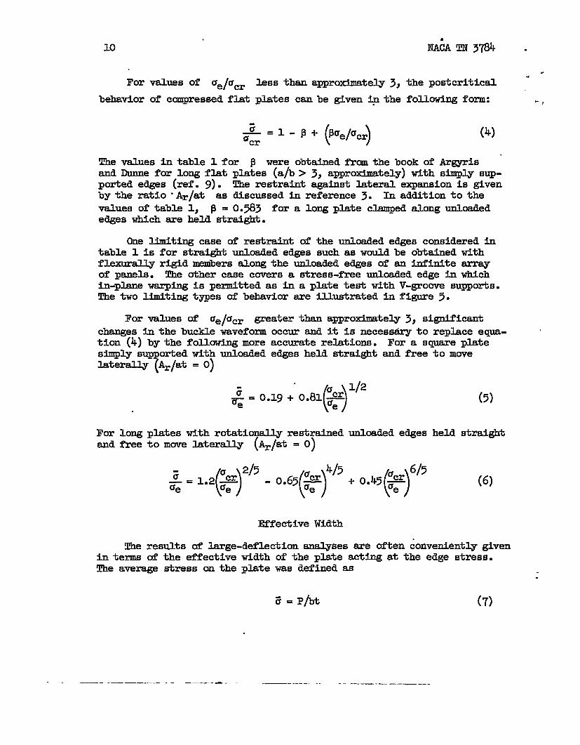
For values of se/au
behavior of compressed flat
less than apprmdmatel.y 3,
plates can be given ~ the
NA6A TN 3784 .
.the postcritical “
fOllowing fOrm: -,
(4)–= ‘ - ‘+ (’”J+iJ
~cr
The values in table 1 for f3 were obtained frcm the book of Armrisand Dunne for long flat plates (ah > 3j approximately)with s@$ly sup-ported edges (ref. 9). The restraint against lateral expansion is givenby the ratio -Ar/at as discussed in reference 3. In addition to the
values of table 1, 13= 0.583 for a long plate clamped along unloadededges which sre held straight.
One limiting case & restraint of the unloaded edges considered intable 1 is for straight unloaded edges such as would be obtained withflexurdly rigid menibersalong the unloaded edges of an infinite arrayof panels. The other case covers a stress-free unloaded edge in whichin-plane warping is permitted as in a plate test with V-groove supports.The two limiting types of behavior are illustrated in figure 5.
For V8hES of Ue/dcr greater than a~roximately 3, significantchanges in the buckle waveform occur and it is necesmiry to replace eaya- ‘tion (4) by the following more accurate relations.simply s
7
orted with unloaded edges held straightlaterally Ar/at = O)
; ()u1/2
~ = 0.19 + 0.81 ~ae
For a square plate—and free”
For long plates with rtiationally restrainedand free to move laterally (Ar/at = O)
unloaded edges
:= ’”2(%Y’-0”’5(*r’’+0”45(*r
to move
(5)
held straight
(6)
Effective Width
The results of large-deflection analyses are often conveniently givenin terms of the effectiw width of the plate acting at the edge stress.The average stress on the plate was defined as
.
3= P/bt (7)
.
. —. ——— .—-. —.—. . . . .— - ------ .- ..-.. -— .=__

IiACATN 3784 u
.’ .
For the same load P, it is desired to find an effective width at each. edge be acting at the edge stress:~,
P = Ue2bet (8)
By substituting equation (8) into equation (7),
:. ae
~e ~ (9)
By rearranging eqyation (4) and by use of equation (9) the followingeffective width rehtion can be obtained for values of ae/Ucr less t~3:
(10)
For vdlES Of ue/Ccr greater than 3} equations (~) and (6) may be used
directly in conjunction with equation (9).
The effective width discussed in the foregoing ccmments is concernedwith the load-carrying ability of the plate after buckling. A secondtvne of effective width is associated with the stiffness of the plate
.
.
“...against further compression. The reduced effective width is
From equation
For values of
be found fromsquare plate:
()2be = ddTr ~
(4), therefore
()
~br=P
‘e/Ucr greater than 3, the
eqpations (5) and (6) in the
reduced effective
fo12mwing forms:
and for the long plate:
()2becm 1/2
T. ()=0.19+ o.405q-
def-=d as
(U)
.
(12)
width C=
For the
(13)
(+)r:oe7+#5-o.13 (&y5-o.09(&f’5 (,4]
.-. — . . .. —.. —— .— .—— ——. .—-— .—-—--—--- -— —-

12
.
arefor
NACATN 3784 =..
As indicated in figure 1, the effects of small initial imperfections “.
confined primarily to the region of the theoretical buckling stress ‘fI.atplates. Thus, small initial hnperfections lower’somewhat the -,0
values of effective width as compared with those for a perfect plate upto approximately ~e/~~ = 2. Beyond this, the effects are negligible.
Since the reduced effective width depends upon the derivative asindicated by equation (U), the effect of small initial imperfections isto lower significantlythe values of reduced effective width as ccmparedwith those of perfect plates below the theor~ical buckling stress.Beyond this, the effects are negligible and the values for a perfectplate may be safely used.
All the foregoing results on effective width are based on analyseswhich assume the plate to be elastic in behstior after buckling. Mayersand Budiansky introduced plasticity effects in the postbuckling saalysisand computed the effective width of flat plates of 2024-T3 aluminum alloythat buckled at 0.3} 0.4, O.~} and O.6 of the compressive @eld strength(ref. 8).
The results of this analysis indicate that the effect of plasticityis to reduce the effective width as compmed with that derived from elastictheory for values of ~e/em (edge s$rain/critical strain) up to approxi- ,
mately 3. Beyond this, elastic theory yields smewhat consemativevalues●
Failure of Flat Plates
The termination of load-carrybg ability of flat plates appears tobe dependent upon the boundary conditions along the unloaded edges. Asdiscussed in the section “Failure of Flanges,” failure of a flange isintimately associated with the highest attainable value of edge stresswhich in turn is a function of the edge-stress intensity. Thus, varia-tions in edge-stress intensities due to cliffering boundary conditionsmay be expected to result in variations in the failure behavim.
ti discussing the failure of flat plates, it is necessary, there-fore, to identify carefully small dHferences in boundary conditionswhich by themselves may not cause a difference h buckling stress. Forthis purpose, the discussion will be concerned with the failure of flatplates for which:
(a)
(b)
The unloaded edges do not warp and thus remain strai@t in theplane & the plate (v = Constant) (fig. 5(a)).
The unloaded edges are free to warp in the -plane of the plate(ay = O)(fig. s(b)).
...-

NACA TN 3784 13
. . .
.
.
.
(c) The unloaded edges are supported by columns of solid cross. section.
The load-carrying capacities of flat plates with straight edges con-strained to remain straight have been ccmputed by Mayers and Budianskyfor 202&T3 plates that buckle elastically at 0.3, 0.4, 0.5} and 0.6 ofthe compressive yield strength (ref. 8). Although the average compressivestress did not have a maximum value in the range of -end shortening con-sidered (up to O.010) the curves were very flat from a strain of approxi-mately 0.006 on. Thus, the average compressive stress at a strain of0.010 was taken as an tidication of failure. .
The results of this analysis, together with experimental data onfailure of flat plates with various boundary conditions of Andersonand Anderson (ref. 10), Botman (ref. 11), and Besseling (ref. 12), areshown by the lower curve and test points in figure 6.c A very significantfact brought uut by the theoretical analysis is that the load-carryingability of plates with straight unloaded edges may be sigdi’icantlyhigher than that of plates with umloaded edges which are free to warp.
Plates tested in V-groove supporting fixlmres are free to warp.In addition, out-of-plane disp~cements at the unloaded edges are notentirely prevented after buckling because of lateral-shorteningin thecentral region of the plates as shomi in figure 5. Similarly, the post-buckling behavior of compressed square tties closely follows that ofplates tested in Y-grouve supports. For the tubes, both warping andout-of-plane displacements of the corners are evident after failure.
The hportance of the boundary conditions in relation to failureis further supported by ~erimental data of Botman (ref. 11) and Besseling(ref. 12) on wide plates divided into three bays by a series of opposedknife edges running longitudinally. It can be observed in figure 6 thatthese data Me between experimental data on plates with warped edges andtheoretical results on plates with straight edges. Since the outsidee~s in the three-bay tests are free to warp, it is yossible that higherstrengths would be achieved in tests of plates with a greater number ofbays.
It is convenient to use a semieqirical relationship in order tounify the theoretical results of Mayers and Budians@ (ref. 8) and theexperimental data. For this purpose, the following egyations are assumedto apply:
1%=&j (’c-(J’nucY)
(’(15)
Gf = u- u= > (a)l/nacy)
. . .. . .—— _. . .-— ————... ..__ .—

NACA TN 3784 .14
This is the same eqpation used tithe section “Failure of Flanges” to fit ~ ‘-the dqta for hinged flanges.
From the logarithmic plots shown in figure 6, the values of a-.
and n were determined and sre given in table 2. It is to be noted thatthe theoretical results cover a small although sufficient range to permita reasonably precise esttite of the a and n values. The data forsqusxe tubes presented in figure 6 cluster for the most part in a narrowregion. However, the line drawn for the V-groove test data fits thesquare-tube dhta well. The square-tube data are discussed at sane lengthin the section ‘!Cripplingof Formed Angle, Z-, and Channel Sections.”
It is interesting to ntie that the slope of the lines drawn throughall of the test data has a value of 0.58 as compared with the theoreticalvalue of 0.80. Apparently, in the three-bay plate tests, the effects ofthe outside edges, which are free to warp, are stild.sufficientlypro-nounced to cause the plate to act more in the manner of the V-groove platethan in that of the theoretical straight-edgeplate.
These results serve to indicate that although V-groove and squaxe-ttie tests may be representative of complex wing structures as far asbuckling is concerned, they may or may not yield conservative data onfailure depending upon the compression cover-supporting structure. Forexample, in a multiweb wing design, the continuity of adjacent panels .
tends to prevent warping af the unloaded panel edges. In such cases, itis possible that the failure relation wi~ Me between the theoreticalrelationship as an upper bound and the three-bay plate data as a lowerbound.
The test data for V-groove plates end square tubes are also shownin an alternate form in the u~er curve of figure 6. This form of pre-sentation is used extensively throughout the remainder of this reportand therefore it is convenient to have the flat-plate failure data inthis form. !J!hebuckling stress of a long, flat, simply supported plateis given by
aCr = KE(t/b)2 (16)
By substituting eq-tion (16) into equation (15) and rearranging terms,
In a simplified form
~f =
[()]
~t E l/2mTCy b acy
(17)
.
(18) ,

u
.“
-,
. NACA TN 3784 15
.
The test data in the upper curve of figure 6 are pltited accordingo to the parameters of equation (18) and it can be observed that for
??f/acy< 0.9
of~andmobtained frmn
From the
the data correlate within *1O percent limits. The values
in equation (18) were computed from the a and n valtistable 2
sectionload of the flange is
as follows:
p = a(3.12)‘*425s 1.421
J (19)m= 2(1 - n) = 0.85
“Failure of F-s” it is lamwn that the failuredirectly related to the stress intensity at the—
supported uuloaded edge. It is reasonable to assume, therefo~e, thatfailure of the flat plate is related to the edge stress tite~ity.
A qualitative esthete of the edge stress intensity in the post-buck.1.edphte can be obtained from figure 5. For the plate with straightunloaded edges, the value of the membrane stress ax at the edge is
approximately the same at the center as at the ends, with the value ofthe mcnibranestress cry varying along the length. For the plate with
distorted unloaded edges, however, the value of ax at the edge increases
appreciably toward the center as compared Wiih that at the ends.
The value of the edge stress intensity depends primarily upon thevalue of Ux and only secondarily upon ~ and T= which arise afber
buckling has occurred.,,Therefore, it appears that the edge stress inten-sity at the center of the plate with distorted unloaded edges may be-appreciabl.yhigher for a given value of average compressive stress ax
than in the correspondingplate with straight edges. In conjunction withthe fact that in the V-groove and square-tube tests some lateral bendingof the edges may occur, the dtiferences in e6ge stress intensities betweenthe two types of plates could account for the data presented in figure 6.
If the unloaded edges of the phtes are suppofied by columuE whichfail at a value of edge stress below that associated with failure of theplate in a V-groove or three-bay test, for example, then the data pre-sented in figure 6 cannotbe used. In its place, the lead-carrying abili-ty of the plate may be estimated by use of equtions (4) to (6)in whichUe now represents the strength of the column.
The probla of failure of stiffened panels under compressive loadsis treated at length in reference 1. The failure of stiffened panelsunder shear loads has been thoroughly presented by Kuhn, Peterson,and Lain in their development of tension-field theory (ref. 2).
—-—.. —-...—-.—. — . — .—— — . . ——.. .

16 NACA TN 3784 .
“.
POSTSUC~G BEHAVIOR AND FAILURE
compressed CURVED PIATES
OF
.
As discussed in reference 5, the buckling behavior of curved platesunder axial compressive loads is governed by the curvature parameter ~.
At values of Zb less than 10, approximately,the buckling stress of
curved plates is essentially the same as that of flat plates with ccan-parable boundary conditions. In the region at ~ between 10 and
roughly 1,000, the transition between flat-plate and ccmplete-cylinderbehavior occurs. In this region, the boundary conditions along boththe loaded and unloaded edges exert significant influences upon thebuckling stresses. Beyond values of ~ of roughly 1,000, long-cylinder
behawior predominates, in which boundary conditions are insignificant.
Curved plates which are characterizedby ~ values beyond the
flat-plate region exhibit discontizmities after buckling such as shownin figure l(a) for cylinders. This behavior is typical of curved ele-ments under compressive loadings. At values of Zb in the neighbor-
hood of 10, this discontinuityy is relatively small and such plates cancarry loads considerably in excess of the buckling load. As ~
increases, the discontinuitybecomes so large that the postbuckling loadsare always below the buckling load. In such cases, buckling and failureare coincident. Experimental evidence indicates this to be true for com-pressed cylinders and curved plates of large values of ~.
In this section, the postbuclding behavior of curved plates whichfall in the transition region is reviewed. Experimental data on effec-tive width and failure are presented from which generalized empiricalformulas
Coxclamped,Based on
are derived.
Postbuckling Behavior
and Pribram have considered the postbuckling behavior of long,curved plates with negligible lateral restraint (ref. 13).a semiempirical approach, the data shown in figure T(a) were
presented for cur%d plates-(~ <-60) with relatively small initial
imperfections. Somewhat larger initial imperfections alter the shapesof the curves in the region of buclding although they cause insignif-icant changes in the postbuckling behavior.
In figure T(a), the dashed lines =e used to indicate schematically .the behavior of the curved plate at buckling in an ideal controlled-deformation-typetesting machine. This region is most sensitive toinitial hperfections as .welJ-as to the elasticity of the testing machine. “’

.
NACAm 3784 17
Furthermore, various interpretations can be used to define the bucklingload under different loading systems. As a consequence, the dashed linesare to be viewed as an indication of the behawior of the curved plate atbuckling and not as an attempt to define the buckling load itself.
Since it is somewhat difficult to define the buckling load precisely,
the data displayed in figure 7 are in terms of E(t/b)2 instead of Ucr
as used for flat plates.the buckling coefficient
directly in terms of EThus,
A further advantage
This has the advantage of avoiding the use of~ and permits presentation of the resultsand the geometric parameters of the curved plate.
c7c#2(l=v2)=Et2
Yc?lsc ()F
of this method of presentation lies in the
(20)
experimental fact that the buckling load tends to decrease significantlyunder successive loadings. Test data of Cox and Clenshaw (ref. 14) andof Jackson and Hall (r&. 15) indicate that the buckling region is sig-nificantly affected won reloading although the postbuckling regionappears to undergo negligible change.
The ssme data also indicate that in the postbuckling region plas-ticity effects become important soon after buckling with the result thatthe postbuck~ng curves generally have concave-downward characteristics.
.In
culated
Effective Width
figure y(b), the effective width of curved plates has been cal-from the data of figure y(a). These curves are intended to indi-
cate schematicallythat the effective-widthbehavior of slightly curvedplates is not significantly different from that of flat plates. The onlyimportant difference is that a discontinuity may appear in the effective-width data for curved plates at values of Zb greater than 30, a~r~-mately. The magnitude of the discontinuity is associated with the jumpwhich occurs at buckling and is significantly affected by the magnitudeof the initial imperfections.
A theoretical analysis of the effective width of long, simply sup-ported plates of slight curvature (~ less than 10) has been conductedby Levy (ref. 16). It was concluded that when the bucliledepth beccmescomparable with the sheet thickness, the effect of initial curvature onthe load carried in adal compression becomes negligible. The resultsindicate that when the edge stress is approximately twice the bucklingstress of the corresponding flat plate, the effective widths are sti-stantieXly the sane. These results are in agreement with figure y(b)for values of ~ less than 10.
. .. .— —.. ___ _ _ .—. —— — ——— —. —..

18 NACA TN 3784
Because of the limited range of this theoretical investigationboth - -from the standpoint of the low values of Zb (O, 5, and 10) and the
relatively smdll range of 2be/b considered (1 to O.5),it is necessary --to adopt-an empirical apprcach to this probla.
The available test data are for long, clamped, curved plates.Ramberg, Ievy, and Fienup (ref. 17) tested multiple-bay curved panels of2024-T3 aluminum alloy stiffened by sturdy limed Z-extrusions which pro-vided clamped boundary conditions along the unloaded edges of the plates.The data for which the edge strain was below the proportional limit fallinto two Zb groups of O to 8 and 24 to 31 and are shown in figure 8.
Additional test data on 2017-T3 aluminum-alloy plates clamped alongthe unloaded edges were presented by Jackson and Hall.(ref. 15). Thedata shown in figure 8 zme from the qecond series of tests and includefkt pktes (Zb = O) =d curved plates with ~ values ranging from 4to 125.
A study of the data presented in f@ure 8 reveals that an apparentdiscontinuity occurs in the region of ~/Ue (= 2be/b) between O.5
and 0.4. The data of RaMberg, Levy, and Fienup (ref. 17) indicate that,for the ~ ranges of O to 10 and 24 to 32, the effective-width rangefrom 1 to 0.45 can be represented by the following equation within “
*1O percent lJmits:
for 2be/b >0.45. The buckling coefficient
plate and may be determined from reference 5:
Yc~%=
12(1 - V2)
Equation (21) also represents the Jackson andflat and curved plates.
(a)
& is that of the curved .
(22)
Hall data (ref. 15) on
Below effective-widthvalues of approximately 0.45, the test dataof Jackson and Hall (ref. 15) appear to follow the trend of the failurelines for flat and curved plates. The failure lines me obtained fromfigure 9 as discussed in the next midsection. The equation for the linepassing through the effective-widthtest data for both flat and curvedplates (O ~ Zb ~ ~) as shown in figure 8 is
.
(23).

NACA TN 3784 193
,r ,“
for ~e/b<ook5. The buckling coefficient ~ is for the flat plate.u In this case, for a long clamped flat plate, ~ = 6.3 as indicated in
r figure 8.
Since equations (21) and (23) are based on test data which cover arather limited range of Zb values, they should be used with some
caution beyond ~ values of a~roximately 30. It does appear, however,that the,effective width of flat plates tends to act as a lower limitfor curved plates. ‘l?hisis substantiated not only by the experimentaldata for figure 8 but also by figure 7(b) and the failure data offigure 9.
Beyond ~ values of n, figure 7(b) @dicates that large discon-
tinuities may appear in the effective width curves immediately afterbuckling. For values of ~ large enough for the curved plate to actas a ccnnpletecylinder, the discontinuity can be expected to drop directlyto the failure line, since in this case buckling and failure are coincident.
Failure of Curved Plates
The only reliable data on failure of curved plates with well-definedboundary conditions are from Jackson and Hall’s second series of tests(ref. 15). The jigs used for these tests not only clamped the unloadededges but also tended to restrain any in-plane warping of the curvedplates after buckling.
As mentioned previously in this section, it is nti advantageous topresent test results for curved plates in terms of the buckling stress,as used in the sections “Failure of Flanges” and “Failure of CompressedFlat Plates” for flat plates. !lhisis due to the difficulty of preciselydefining the buckling stress because of sensitivity to initial imperfec-tions. Furthermore, ~ is not constant but is a function of ~ and
may change appreciably upon successive loadings. Thus, it is desirableto use the alternate form of presentation given in the section““Failureof Compressed Flat Plates” and used for the V-groove-plate test data.
As shown in the preceding sections, the failure strength of flatplates which buckle elastically can be expressed in the following form:
.
.
~f .a~
n
‘cr-() Ccr
Multiplying both sides of equation (24) by
Zfl-n
()
Ccr—=a —uCy uCy
%l=cy
.
(24)
(25)
- .—. - .-. . — . . . .. —— -- — — — -.— —.. - .. .

20
The buckling stress of a curved panel is given by
NACA TN 3784 .
..
(26) -
By substituting equation (26) into equation (25)
Ina
more
~ = %’-”&#~2(1-n)(27)simplified form this becomes equation (18).
Equation (18) is equivalent to equatian (24), although it is in aconvenient form for correlating Jackson and Hall’s test data on
failure of curved plates (ref. 15). These test data are shown in fig-ure 9 according to the parameters of equation (18). It is to be nutedthat the values of Ucy were taken as 85 percent of the tension yield
strengths since only the latter were given. The data were divided into.several ~ ranges and are shown in figure 9.
Within approxhnately t10-percent limits, eqyation (18) fits thetest data in
The range ofdf/ucy less
test data on
the fOlhiig form:
‘ [()]0.85
zf— = 2.01:* 1’2
Zf
—<;fa acy (28)‘Cy
validity of equation (28) probab3y applies for values ofthan 3/4, a value obtained in the preceding sections. No
curved plates are available to establish this limit.
Equation (28) apparently gives a reasonable fit to all the test datafor values of Zb between 10 and 125. The tits for the Zb range between
O and 10 consiste?rtlyfall on the lower lo-percent Mmit. For this range,it is suggested that a value of
CRITPLING OF EXTRUDED
The failure following localvaxiously referred to as ~
fl= 1;79 be used in eqyation (28).
Z-, CHANNEL, AND H-SECTIONS
bucltLingof stiffening elements isaverage strength, ultimate strength,
crushing-strength, or crip@ing stre&h. The last term is in commonuse in the aircraft industry and is associated with the short-columu .region (L’/p less than approximately 20) where the strength does notvary significantly with the length of the stiffener. The term cri@lingstrength is used in this sense herein. .
.

NACA TN 3784 21
.
. Fran the standpoint of local buckling (ref. 4), the stiffener crosssection is envisioned as an asseniblageof plate elements. 5e boundaryconditions along the unloaded edges of each of the individual plate ele-ments at a common junction are associated with rotational restrahts pro-vided by adjoining plate elements. The junction may be the filletedcorner of an extrusion or the bend line of a formed section.
Early attempts to determine the crippling strength of stiffeningelements were based upon the buckling behavior of the elements. In suchanalyses, the crippling load was taken as the sum of the buckling loadsof each of the plate elements ccmpri@ng the stiffener cross section.Such analyses are typified by methods presented in the book of .Sechlerand Dunn (ref. 18).
Based on the knowledge that the failure load of a flat plate canappreciably exceed the elastic bucldlingload, later analyses attemptedto refine the method of calculation of stiffener crip@Lng strengths.Such methods are in wide use in the aircrti indmtry for sections ofgeneral shape and differ possibly only in minor details from that pre-sented by Crockett (ref. 19).
For equal flange stiffeners such as Z- or H-extrusions, extensivetest data are available for sevez%@ materials. The s-harpcorners andre@tively uniform stress-strain characteristics in the cross sectionsof extrusions has permitted a synthesis d these data in a simple form.A relationship invohing the buckling stress of the section and thecompressive yield strength of the material is related directly to thecrippling strength.
For formed Z- and channel sections, the relationship smong bucklingstress, compressive @eld strength, and crippling strength appears to beinfluenced by additional factors. These include the finite radius ofthe rounded corner and the increase in compressive yield properties inthe corner due to the forming process!
These effects have recently led Needham to propose a revised methodof analysis for formed sections of general shape (ref. 7). In thismethod, the .crippl.ingload of the stiffener is obtained by sunuuingthefailure loads of each of the corner elements comprising the stiffenercross section.
In this section of the report, a semiempirical analysis is presentedbased upon the knowledge gained from the preceding sections on failure offlanges and flet plates. This analysis serves to unify test results onvarious types of stiffening elements and also provides some physicalinsight as to the factors operative at failure. Available crip@ing testdata on Z-, H-, and channel extrusions are reviewed in this section.Formed angle, channel, and Z-sections are reviewed in the following
. —----- ...-. _—. .._. ._ —.= .. .. —— —-... . . .

22 NACATN 3784 -
.section and methods of analysis for sections of general shape are pre-
.
sented in section after next.
SemiempiricalAnalysis of
From the flat-plate analysis presentedCompressed Flat Plates,” it can be ~ectedwill influence the phstbuckling behavior of
.
crippling
in the section “Failure ofthat the following factorsstiffened elements:
(a) The de~ee of rotational restraints at the unloaded edges(b) The degree of warping and lateral bending of the unloaded
In addition, it can be anticipated that the following factors willence
such
crippl&g d the stiffener:—
[
c) The corner Configwxrbiond) The stress-strain characteristics of the material.nonuniformity of stress-strain characteristics in theas occurs in formed sections
Theoretical postbucm analyses of flanges and flat
edges
influ-
and in partic-cross section
plates indicate—a definite relationship among the average stress~ the-critical stress,and the stress at the unloaded edge of the element. The principal effectof small initial hperfections is to replace the discorrtinuitybetweenprebuckling and postbuckling behavior, which occurs at the critical stress,with a continuous relation. In such cases, the theoretical relationshipsbetween average, critical, and edge stresses cam be gpite accuratelyfitted by an equation of the following type:
(29)
wh-e a and n reflect the large-cleflection behavior of the elementas given by conditions (a) and (b) above for postbuckling behavior.
From the theoretical analysis of failure of fhnges given in thesection “Failure d Flanges,” it was observed that the maximum averagestress ~f is attained when the edge stress reaches a relatively &ge
fraction of the compressive yield strength of the material. Thus, itappears plausible to assume that failure occurs when
‘e = bucy (3Q)
where b is a function of the stress-strain characteristics of the .
material and the edge stress intensity in the element. The coefficient bpresumably reflects the influence of items (b), (c), and (d).
.- —

.
NACA TN 3784 23
By substituting equation (30) into equation (29),
Zf n
()
n UCy—=ab —‘cr ‘cr (31)
Letting a = abn, eqpation (31) becomes equation (24).
Equation (24) has been used in the precedi~ sections to fit thetheoretical data on failure of flanges and flat plates with undistotiedunloaded edges. In both cases, a value of n = 4/5 gave a good fit tothe theory and available test data.
The usefulness of eqmtion (24) has been demonstratedto some extentin the preceding sections where theoretical data ere available. In sub-se~ent sections, it will be shown to be of considerable value as a meansof correlating test data on elements of complex cross section for whichtheoretical failure analyses do not exist.
The usefulness of equation (24) was demonstratedby Schuette incorrelating an extensive amount of test data on formed and extruded equalflange stiffeners (ref. ~). The analysis in this section follows inbroad outline that of Schuette in an interpretation of the test data.The recent publication of theoretical analyses of the failure of flangesand flat plates, as reviewed herein, has provided data which substantiatescme of the assumptions and lend confidence in the approach.
-sis of z-, ~1-, and H-Extrusion Data
An extensive smount of test data on equal-flange Z-, ch+nel, andH-extrusions of various aluminum and magnesium alloys has been correlatedon the basi$ of eqyation (24) by Heimerl (ref. 21) and Schuette (ref. 20).The extrusions tested were characterizedby sharp fi21eted corners withrelatively uniform stress-strain characteristics over the cross section.
Test data for H-, Z-, and channel extrusions are shown in figure 10for four aluminum alloys and one magnesium alloy. The data were takenfrom the references listed in the reports of Heimerl and Schuette. Thesedata were fitted according to equation (24) with the values of a and ngiven in table 3 for values of ‘crl”cy less than 3/4, approximately.
It is to be noted that, for all extrusions, values of ~/t ranged from18 to 23.
In prepering the specimens for these tests, the Z- and channel sec-tions were obtained by removing flanges from the H-extrusions. Conse-quently these data are from specimens of very similar properties and canbe used to obtain a reliable esthate of the various factors influencing
___ ..-. —.. ..— —. — ——. —. .—-. --..-——— —-..— . - ---

24 NACA TN 3784.
failure as discussed under items (a) to (d) in the subsection “Semi- .empirical halysis of Crippling.”
The degree of rotational restraint at the unloaded edge of the flange -(the element in the cross section which buckled first in these tests) isinfluenced by the ccmner configuration and the relative dimensions of theflange and web. The corner configurationwas substantiallythe same forall specimens and, therefore, no estimate of this effect can be obtainedfrcanthese tests.
The degree of rotational restraint at the unloaded edge, item (a),varied between simple support and clamped as influenced by the relativeflange and web dbensions bf/t+ A range of values of bf~ between
0.55 and 0.83 was covered in the H-ex&usion tests. An analysis of thedata did not reveal any systematic variation in the a values with thisparameter. Apparently, the influence of the rtiational edge restraintsis accounted for in determinhg the critical stress of the section anddoes not have any further effect upon the crippling strength.
The stress-strain characteristics of the material, item (d), doappear to have a slight effect upon the value of a. This can beascribed to the influence af the value of b as given in eqxkion (30).From the value of a listed in table 3, it can be observed that thereis a consistent trend for all three sections. Aluminum alloy 2014-T4 hasthe highest values of u, alloys 7075-T6 and O-lHTA have the lowest, andalloys 2024-T4 and R303-T have a~rmdmately the ssme values which are Fintermediateto the other values.
The influence of warping and lateral bending of the unloaded edges,item (b), is clearly evident from the clifference in n values betweenthe H-sections and the Z- and channel sections. Theval.ueof n=O.8obtained for the H-sections is the ssme as that for flanges and flatplates with undistorted unloaded edges. Evidently, the opposed flangesof the H-section prevent any wa&ping of the flanges at the corner. Infact, the values of a for the H-section and hinged flange agree closely.
For the Z- and channel sections, the absence of an opposing flangeat the junction to the web permits some warping and possibly some lateralbending to occur. Thus, the value of n = 0.72 for Z- and channel sec-tions is less than that for H-sections. This is in agreement with thetrend observed for flat plates in which the value of n for plates withwarped edges was less than for those with undistorted edges. For extrudedZ- and channel sections, apparently the web and fi~eted corner act so asto prevent scauewarping of the s~orted unloaded edge of the flange. Thiscan be judged by the value & n = 0.72 for the z- and channel sectionswhich is intermediate to n = 0.80 for undistorted edges and n = 0.65obtained for fIat plates with edges free to warp.
.
—. —.

.
,-
,-
NACA TN 3784
Design Data for Z-j
For design purposes, it maycise values of n and a givenfollowing formulas for values of
(a) For H-sections:
Channel, and H-Extrusions
not be necessary to use the
25
rather pri-ntable 3. He-~rl has suggested theUcr leSS than (3/4)acy (ref. 20:
0.20 0.80tif= O.80LTcr *cy (3U
(b) For Z- and channel sections:
zf0.80
= o.7’7um%cy (32)
In an analysis of the ssme test data, Schuette has recommended for Z-,channel, and H-sections (ref. 20)
iff = o.80ucr0.25 0.T3
~cy (33)
The differences among these formulas is considerably less numericallythan the scatter of all the test data when variations.due to materialproperties and section configuration are not considered.
All of the formulas considered thus far, (eqs. (24) and (31) to (33))apply for values of acr less than a~roximately (3/4)ucy. This gener-
ally corresponds to cases where buckling is elastic. For cases where
‘cr exceeds (3/4)acy2buc~ generally occurs in the plastic range
and failure occurs slightly beyond buckling as shown in figure 11.
From an analysis of test data, Schuette has proposed for values of
‘crlccy greaterthan3/k (ref. 20)
af = l.o+acr (34)
where U= is computed according to methods given in reference 4 using
the appropriate plasticity-reductionfacto?.
From the same test data, Heimerl (ref. 21) suggested an extensionof the secant-modulusmethod of Gerard (ref. 22). In this case, forvalues of Ucr/ucy greaterthan3/4,
[)Ir,#%’s tv2ijf = —
12(1 - F) bw(35)
. —. ... . .. -—. . ..— .Z _ —.-...——. — .--_.-—_ —___ .. ..-

26 NACATN 3784 - “
-.
Hetierl and Roberts (ref. 23) investigated the short-time behavior.
of aluminum-alloyH-sections at elevated temperatures up to 6000 F. Thetest data are shown in figure 12, frcm which it can be observed that the
.
relationships established at room temperature are satisfactory for short-time loading at elevated temperatures.
CRETYJ3YG OF FORMED ANGIE, Z-, AND CHANNEL SECTIONS
The various factors influencing crippling of extruded sections, asdiscussed in the preceding section, also pertain to formed sections.Several additional factors such as the rounded corner,and increased stress-strain characteristics in the corner region as a result of forming indicatethe desirability of discussing formed sections separately from extrusionsin this presentation. Furthermore, stiffening elements are often formedof alclad sheet and it is necessary to consider the effect of the claddingupon the crippling strength.
A mass of test data on Z- and channel sections formed of 2017-T3and 2024-T3 aluminum alloys was analyzed by Schuette (ref. 20) on thebasis aP eqyation (24). It was found that a value of n = 3/4 fittedthe test data well but that there was a systematic variation of the coef-ficient a with the parameter ~/t which ranged between 18 and 43.
Since a appeared to be constant for extruded Z- and channel sections,the variation in a for formed sections was attributed to the increasedstress-strainproperties in the corners.
In an analysis of the same test data used by Schuette plus data onFS-lh formed Z-sectionszGallaher (ref. 24) found that a simple correh-
tion of the form ~f = f(A/t2), where A is the cross-sectionalarea
of the stiffener, gave a good fit with the test data. Recently, Needhsm(ref. 7) presented test data on formed angles and channels of alclad 2024-T3,2024-T3, and alclad 70~-T6 aluminum alloys and obtained good correlationon the basis of
Gf = C(t2/A)m (36)
A valuefact, am = 3/4
of m = 3/4 gave a good fit with all of Needhamts test data. Inreplot of Gallaher’s data on the basis of equatibn (36) withresulted in excellent agreement with the test data.
.

. .
NACA m 3784
SemiempiricalAnalysis of Angles and Sgyare Tubes
27
The interesting fact evident frcm the foregoing discussion is thatthere are apparently two different correlative schemes which are each ingood agreement with test data. The GalJaher-Needhsmmethod is the shplestsince, for a given material, the crippling strength is a simple function-of the gecmetric properties of the cross section t2/A, or tfi where bis the developed length of the cross section.. However, it is not directlyevident how to generalize equation (36) in terms of The physical propertiessuch as E and uCy of the material. Furthermore, equation (36) is valid
/only for values of df Ucy less than a~roximately 3/4 as in the case of
extrusions. This fact is often disregarded when the data are presentedaccordingto eqyation (~).
The Schuette form of correlation involves computation of the bucklingstress, and, therefore, is not so s~le as the above method. Primarily,the simplicity ts lost for Z- and channel sections because a in equa-tion (24) is not a constant but is a function of ~/t. The advantages of
the Schuette method, however, include the fact that the results are in ageneralized form for various materials since the values of E (in ucr)
and acy appear in the semiempirical relationship. Furthermore, the
range of validity of the relationship in terms of 6f/ucy “isreadilyevident.
,
In preparing t~s review, it became evident that certain relationsmust exist between the two correlative schemes ~hich would permit a gen-eralized approach. It is desirable to retain the simplicity of theGallaher-Nee- method, although in a non-nsionalized form, with therange of validity of the formula readily evident. The bst two featuresare contained in the Schuette method of correlation.
The following analysis presupposes that the available test data fora particular stiffener shape which buckles elastically have been corre-lated on the basis of the two methods discussed above. From the Gal.laher-Needham method eqyation (36)holds and from the Sqhuette method for
~ ~1/n6f = acy, there is equation (24) or
l-n n . .Uf =cmcr u -Cy (37)
It is assumed that the values of C, a,from test data.
At this point, the e~ression am
tion (37). Although this can be done in
m, and n can be established
is to be introduced into eqya-
a generalized manner, it is
..— ....—-— ——... ..— —— _ ....__.--— -.—— .—— --—----

—
28 .
convenient to consider those cases inis constant (such as for equal flangefrom cases where k is a function ofcross section:
where fi issubstituting
NACA TN 3784 -
“-.whichthe buckling coefficient kangles and scj..e tubes) separatelythe geometric parameters of-the - --
t)
2=~KEG (38)“Cr=i i#%j(a2
the claddiw reduction factor discussed in reference 3. Byequation (3~) into equation (37)
.a(~~l-nt 2(1-n)k)
n??f Ucy (39)
Also, for equal flange angles and sqme tties> the parameter %2/A Can
be replaced by t/b with the resultant change in equation (36):
af= E(t/b)m
By equating equations (39) and (40)
l-nt 2(1-n) n
()a(K-~) ~ c1 =
()&
Cy
(40)
(41)
By rearranging terms and defining a new parameter ~, the following rela-tionship exists:
2(1-n)-m$ = d-n~) I= ~ (#nacyn . (42)
By virtue of e@ation (40) and since t/b is proportional.to
()
1/2acr >
m/2~fa~
cr(43)
From equation (37), however,
l-n~f=u
cr(44)
Therefore, for equal flange angles and sqme tubes the exponents of Ucr
must be related in one of the following ways:.
.

NACA ‘IN3784 29
.
1 -n=~2
1 -n 1—= —m 2
1
J2(1-n) -m=O
By use of equations (45), equation (42) simplifies to
13=d”n=u
(~E)m/2acyl-(m/2)
Finally, equations (39) and (40) become
The range of validity of
(45)
(46)
(47)
eqyation (24) is valid forequation (47) follows from equation (24). Since
ii?f~ s wn
it follows from equation (46) that in terms of ~
6f<0 l/n
~cy -–() +n
For Val.ueSof ~f/Ucy greater than those given by equation (49)
iff=ucr .
(48)
(49)
(50)
The application of this method of generalized analysis will be demon-strated by correlating data on squsxe tubes and e@ flange angles.
Crippling of Square Tubes and Equal Flange Angles
A sufficient, although not extensive, amount of available test dataon crippling of extruded square tties of several aluminum alloys has beensumarized by Needham (ref. 7). .The data for tubes for which 5f/ucy
was less than approximately 3/4 were correlated according to the Gallaher.Needham methd, Schuette method, and the generaJAzed method presentedherein.
-—.______ -—— . -— —-- —-— ______ _ . _

30 NACA TN 3784
From test data shown in figure 13, it can be observed that m = 0.85 . -fits the data according to the Gallaher-Needhsmmethod and n = 0.575 fitsthe data according to the Schuette methd. According to eqyation (45), therelation between m and n is satisfied without any adjustment in these ‘-values. In terms of the generalized correlation for the sqpare tubes
(51)
dffor —~C).7. Also included in figure 13 are some data on rectangular
~cytubes of 2024-T3. It canbe observed that the data are in agreement witheqpation (51) which is the same eqyation obtained for V-grouve plates inthe section “Failure of Compressed Flat Plates.”
Needhsm has conducted tests on crippling of equal flange anglesformed of 2024-T3, alclad 2021t-T3,and alclad 7075-T6 aluminum alloys inthe -T condition toan inside radius approximately eqyalto 3t (ref. 6).The test data for each material.were correlated by Needham accordingto
rff= m/b)3/4 (52)
As pointed out by Needham, an exponent of m = 3/4 gave a satisfactoryfit,-although not necessarily the best fit, to the test data. !J?hevaluesof C! as well as the physical properties of the materials are tabulatedin table 4.
Although alcald angles were tested by Needham (ref. 6), the bucklingstresses for a large majority of the test points were well below the pro-portional limit of the cladding. In such cases, no correction for thecladding, as discussed in reference 3, is required. The few test pointswhich theoretically do reqplre a correction were not revised because ofthe minor nature of the correction in this case.
In order to provide additional data for use with the generalizedcrippling formula, Needhsm’s test data for the 2024-T3 equal angles wereplotted according to the Schuette method in figure 2. Although there issane scatter in this plot, which also exists in Needham’s data plottedaccading to equation (52), the following relation fits reasonably wellas sh~ in figure 2 and by equation (3):
0.575Gf
()= 0.95 - for %s o.g2 (53) -
acr acr ~cy
Thus, avalueof m= 3/4 was used by Needham and a value ofn = 0.575 was obtained from equation (53). According to equation (45), -

5UNACA TN 3784
.however, 2(1 -The discrepancy
.
31
n) = m, a relationship which is not satisfied in this case.is apparently due to the fact that the scatter of the data
permitted some latitude impersonal. jud~nt in fitting the data accordingto equations (30) and (40).
To resolve this discrepancy, all.of Needhamts test data for angleswere plotted as shown in figure 14, according to equation (k7). The aver-age generalized crippling formula for formed angles which fits the datawithin fro-percent limits is ..
[()(” ) ]
0.85df 1/2~Lo.665 ~ ~
b Ucy (54)Cy
for &f/acyS0.92. This formula is valdd for materials with strain-
hardening characteristics similar to thope of 2024-T3 alloy end with abend radius of approximately 3t formed in the -T condition. For mate-rials such as 7075-T6 alloy which have lower strain-hardening character-istics than 2024-T3 alloy, the test data appear to be consistently lowerthan the average curve in figure 14. ~refore, a.value of P = 0.630should be used in equation (54) for such materials.
Needham has also conducted tests on elclad 2024-T3 unequal flangeangles (ref. 7). By defining the term t/b as ~/(bl + b2) Were bland b2 represent the flange widths, Needham obtaihed satisfactory cor-—relation with equation (52) using the value of ~ given in table 4 foralclad 2024-T3 eq@L flange angles. These data are also shown in fig- “ure 14. Apparently, equation (54) is in reasonably good agreement withthese data.
SemiemptiicalAnalysis of Z- and Channel Sections
As & the cases of angles and square tubes, the analysis for Z-and channel sections presupposes that the available test data for sec-tions which buckle elastically have been correlated on the basis of thetwo methods. For the Gallaher-Needhammethod equation (36)holds trueand for the Schuette method there is equation (37).
For equal flange, Z-, and channel sections, the buckling stress maybe determined from the following equtionsented in reference 4:
and buckling coefficients pre-
(55)

32
By substituting equation
‘f =
NACA TN 3784 .
“...(55) into equation (37)
For Z- and channel sections of constant thicknass,
A= (%)[.+ (y)] “t2
(56) . -”
(57)
where ~ and ~ are the web and flange widths, respectively. By
sutmtittiing equation (57) into equation (36)
(58)
By eqwting equations (56) and (58), rearranging terms, and definingthe parameter ~ in a manner similar to that used for angles and squaretubes,
‘ ‘~1-n[+5)7?rn)-mFinally, by substituting equation (59) intocrippling formula is obtained
c
(ijE)%cyneqyation (36),
(59)
the generalized
(60)
which is valid if eqpstion (48) is satisfied.
Note that, in this case, a direct relation between the exponents mand n cannot be established theoretically as in the case of equal-element sections such as angles and square tub-es. For the latter, thebuckling coefficient is a constant and t2/A can be replaced directlyby t/b. For the Z- and channel sections, the buckling coefficient andthe t2/A parameters are different functions Of bf/bw.
Crippling of Z- and Channel Sections
Schuette has analyzed test data on 2017-T3 and 2024-T3 channel andZ-sections formed in the -T condition to an inside bend radius of 3t(ref. 20). In all cases the flange buckled elastically. It was quite
.
..

NACA TN 3784 33
.conclusively established that a value of n = 3/4 in equation (37) gavethe best fit to the test data. This value is practically the same astha~ obtained for extruded Z- and channel sections; The test data for.the extrusions covered the mow ~/t range from 18 to 23 and there-
fore a fixed value of a = 0.80” (eq. (33)) was used to correlate thedata. The formed sections, however, cuvered a ~/t range between 18
and 43 and, consequently, a variation of a with the parsmeter ~/t
was obtained.
The test data for the 2Q17-T4sections are shown in figure 15(a).In figures 15(b) and 15(c), the test data for the 2024-T4 sections aregiven. Additional test data of Gallaher (ref. 24) on FS-~ magnesium-alloy Z-sections formed in the -h condition to an inside bend radius of4.3t are shown @ figure 15(d). M all these cases, n = 3/4 and thevalues of a listed in table 5 provided a good fit to the test data.
The same test data w&e correlated according to equation (36)andare presented in figure 15(e) in terms of ~f and A/t2. It can be
observed that all data for each material Me along a single line of slapem= 0.75. There is no systematic variation of the data with the param-eter ~/t as occurs in figures 15(a) to 15(d). Thus, correlation
according to equation (36) is evidently simpler and more direct thanaccording to equation (37).
Now that the values of the exponents n = 0.75 and m = Q.n havebeen estab~shed from figure 15, generalized crippling formula (6o)becomes
df [()()]tp& 1/3 ‘“m “
—=$ r acy=Cy (61) “
All available test data for formed Z- and channel sections of 2017-T3,2024-T3, snd FS-lh alloys are plotted in nondimensional form accordingto equation (61) in figure 16. It canbe observed that a value ~fj3= 4.00 in equation (61) fits the 2017-T3 and2024-T3 data withinaU-percent scatter band. The FS-lh data appear te be smewhat lowerwith a value of j3= 3.78. The lower value of J3 is attributedto thelower strain-hardeningcharacteristics ofFS-lh alloy, which result ina smaller increase in yield properties in the corners as compared withthose of the two aluminum alJoys. This effect”is considered in detailin a later portion of this section.
For values of m and n equal to 0.75,a, and C become, from equation (59),
the relations among f3,
.
, :%CL25&+i+f$00m($)0*25 = ,,EIO.; 075 (62)
Ucy “ .
.— .. . ....—..—_ ..._ — -— — ——
.
—. — —.. —.. .

34 NACA TN 3784
An interesting sidelight on the variation of a with the parameter ~/t 4 “-
can be obtained f?xxrthe calculation presented in table 6. ‘RX?values of~ as a function of bf~ were obtai~d frcm reference 4. It cm be -
seen that the parameter listed in table 6 is reasonably constant over thebf~ raage of the majority of the test data. By use of the values
listed in table 6, eqpation (62) simplifies to:
(“90.25
P = 2.14a~ (63)
h order to confirm eqyation (63) bytuse of the values of a listedin table 5, it is convenient to rearrange equation (63) in the form
a= (&)(!Y)-o”= (64)
In figure 17, the data of table 5 are platted and shown in relation toequation (@). A value of ~ = 4.05 fits the data reasonably wellwithin a scatter band of +3 percent. 5s value of ~ was determinedindependently of that obtained from figure 16. Both values of ~ arein close agreement.
Also shown in figure 17 is the value of a = 0.80. which was obtainedfrom egyation (33) for extruded Z- and channel sections. since theextruded sections tested covered only a ~/t rahge from 18 to 23, no
experimental variation of a was observed. However, from the relationbetween ~ and a as given by equation (59), it is reasonable to expectan a variation for extrusions as well as for formed sections. Thedashed line in figure 17 appears to be a reasonable esthate ti thisvariation.
It is interesting to nute that the extrusion line falls below thatfor formed sections. This is ascribed to the increased stress-straincharacteristics in the corners of the formed sections. Apparently, thestrain-hardening due to forming has little, if any, influence upon thevalue of n. Its only effect is to increase the value of a, presumablyby increasing the edge stress at failure as reflected in eqqation (30).
As indicated by eqpation (~), equation (61) is valid below values
of al/n. ~ use of equation (6k), the values of the cutoffs shown infigure 16 can be readily established. Beyond these cutoffs, extensivetest data correlated by Heherl (ref. 21) Indicate that
fi2%#s t 2Sf =12(1 ()-.~2) z
where ~ can be determined from reference 4.
“(65)
.
...
.
. -.

NACA TN 3784 35
.r
Cladding CorrectionL
. The cladding which may be present on formedthe value of the buckling stress as indicated inbuckling load-carrying ability of the section is
sections acts to reduceequation (55). The post-adeqwtely accounted for
by use of the pertknt stress-strain data for the CM materials. Theprincipal effects of the cladding, therefore, include a decrease in thebuckling stress as reflected in the cladding reduction factor ij and aslight decrease in E and Ucy as compared with those of the core
material.
Needham has presented a considerable amount of test data on channelsections of alclad 2024-T3 and alclad 7075-T6 formed in the -T conditionwith an inside bend radius of 3t. The data of figure 16 on 2024-T3 Z-and channel sections can thus be used as a standard of cmnnrisonwiththe alclad 2024-T3 data of Needham (ref. 7) toof correcting for the cladding.
The cladding correction factor ij can beformula given in reference 3
1+ 3(CC1/UCr)f:= l+zf
substantiat~ the method
computed from the followlng
(66)
where f %s the ratio of total cladding th$ckness to total thickness(f =0.10 foralclad2024-T3 and f = 0.08 for aIclad 7075-!r6soys).Since data for the”individual test points were not given by Needham(ref. 7), anuverall correction based on a value of acl/acr =1/2 was
used for the alc@d 2024-T3 data and Ccl/acr = 1/3 for the alclad
7075-T6 data. The values of Ucllucr selected were based on an esti-
mated average value of Ca for the range of test data
values of ~ tend to undercorrect at the higher values
correct at the lower values of ~f. However, since the
a minor nature, this approach appears to be acceptable.
Needham’s test data are presented in a generalized
presented. These
of af and wer-
correction is of
form in figure 18.Equation (54) is compared with the alclad 2024-T3 data by using the valueof ~ = 4.~ obtained from the 2024-T3 data of figure 16. It can beseen that the data fall within the f10-percent scatter b-and.“Such scatterwas previously obsened also for the data on formed angles, figure 14.Inasmuch as Needham’s data scattered within *lO-percent llmits when cor-related according to equation (36), the scatter in figure 18 cannot beattributed to the generalized correlationmethod in this case. Therefore,the method of correcting for the alclad coating appears to be satisfactory.
.
... . . . .._— —_ .. . -—.. .— .—.. -—— -.—--

36 NACA TN 3784
The alclad 7075-T6 data in figure 18 fa31 consistentlybelow the -.
alclad 202h-T3 data.
.
These data are fitted within *lO-percent limits byeqyation (61) with a value of j3= 3.42. The lower strain-hardening-acterifiics of alclad 7075-T6 appear to be responsible for the lower ‘ “value of J3e
Increased Corner Properties of Formed Sections
The increased stress-strainproperties of sections which are formedin the -T condition have been discussed briefly at various points in thissection? Now that the values of ~ h equation (61) have been establishedfor formed Z- and channel sections of several different materials, it ispossible to examine quantitativelythe effects of the increased cornerproperties on crippling.
The average compressive yield strength 6CY of the corners of Z-
and channel sections as compared with that of the unformed sheet hasbeen investig@ed by Heim.erland Roy for 2017-T3 (ref. ~), Heimerl andWoods for 2024-T3 (ref. 26), Woods and Heimerl for alclad 7073-T6 aluminumalloy (ref. 27), and Gallaher for FS-lh alloy (ref. 24). The ratios ofthe average compressive yield strengths of the corner 6CY to the yield
strengths of the unformed sheet Ucy for these materials are presented
in table 7. The data are for sheets formed in the -T condition with thebend line parallel to the grain direction. .
In order to correlate the crippling strengths with the increasedcorne~ properties of formed sections, the pertinent values of ~and u
ICy ‘Cy are presented in table 8.
The values of B as a function of 6cy/ucy are plotted in fig-
ure 19 from Which a fairly consistent trend is evident. The values Inthe last column of table 8 are based on the fact that the crippling stress
o.~for Z- and channel sections is proportional to ~ and acy . Thus,
in attempting to estimate the value of ~ for sections which do not haveincreased corner properties (sections formed in the annealed conditionand subsequentlyheat-treated, e.g.) the values calculated in the last.columu were averaged and are showp in figure 19. This aver,agevalue iswithin &j percent of the computed values of table 8 and is based uponthe assumption that the crippling strength depends primarily upon thecompressive yield strength of the corner. The data except for the2024-T3 material appear to substmtiate this assumption.
Figure 19 also includes the value of P = 3.64 for extruded Z-,
and channel sections. When cmpared with the estimated value of ~ = 3.30.

NACA TN 3784 37
at i5c#7cy= 1.00, it appears that the filleted corner of the extrusion
is responsible for approximatel.ya 10-percent increase in cripplingstrength. .
CRII?PLINGW SECTIONS (l?GENERAL SHAPE
In the section entitled “Crippling of Extruded Z-, Channel, andH-Sections” crippling strength data for extruded Z-, channel, and H-sectionswere analyzed and in the next section extruded tubes and formed angle, Z-,and channel sections were considered. Although such sections are in com-mon use, many other sections such as J-, hat, lipped Z-, and channel sec-tions are widely used. Furthermore, the included angle between variouselements in the cross section maybe considerably different from 90° andthe flanges of a Z- or channel section, for example, maybe of unequaldimensions. Thus, it is necessaryto review available test data on sec-tions not treated previously in order to consider exbension of the semi-empirical methods of the two preceding sections to more general shapes.
EMPirical methods are in wide use in the aircraft industry for csl-culating the crippling strength of sections of general shape. Typicalof these methods is that presented by Crockett (re”f.’19)in which thefailing strengths of the various flat and curved plate elements comprisingthe cross section are suuunedto determine the crippling load of a sectionof general shape. Curves for various materials in which the failingstrength is given as a function of b/t or R/t have been presented forplates ,withone edge free and those with no edge free.
Recently, Needham proposed’a method of calculating crippling strengthsof formed sections in which the cross section is divided into a series ofequivalent angles with one-edge-free and no-edge-free conditions (ref. 7).Data for the failing strength as a function of A/t2 of the equivalentangles were obtained from tests on channel and sqyare-tube sections such .as discussed in the preceding eection. The crippling load of sections ofge~ral shape is obtained by summing the failing loads of the variousequivalent-angle elements of the croak section.
Needham stated tkat an advantage of this method is its inclusion ofthe influence upon crippling of the increased yield properties in thecorners of sections formed in the heat-treated condition (ref. 7). Fur-ther, the division of the cross section into angle rather than plate ele-ments places the “cut” in the least sensitive region of the plate.
Although the last argument appears to be rather abstract, focussingattention on the corner by considering the equivalent angle does appearto be of conside=ble significance. As discussed -inthe section “Failureof Compressed Flat Plates,” failure of an element which buckles elastically
. . ..— .._— —. — —.. . —. ——— . ..—

38 NACA TN 3784
is intimately associated with the stress intensity at the unloaded edge. --.
Since the corner provides the suppoti for the unloaded edge, the nuniberof corners h a section of general shape should have a significant influ- -.ence upon the crippling strength.
Indeed, the analysis of availsble test data tobe presented in thissection suggests that only two gecauetricparameters are required to deter-mine the crippling strength of many sections of general shape for a partic-ular Msterial. One parameter is A/t2, which, for a section of constantthickness, is the developed length-thicknessratio. The other parameteris the number of corners c which subdivide the developed length into aseries of plate elements.
In order to indicate the influence of the nmiber of corners uponcrippling strength, the gene- shapes to be considered in this sectionare treated according to this parameter. Thqs, one-corner elementsinclude equal- and unequal-flange-angle,T-, and cruciform sections.Two-corner elements include eqti- and unequal-flange, Z-, channel, andJ-sections. Sections with a number of cornqrs greater than two includelipped engles, lipped Z- and channel sections, sndhat and limed hatsections.
A generalized formula
w
One-Corner Elements
for determining the crippling strength ofequal and unequal fhnge formed angles was obtained in the preceding sec-tion based on the analysis of a mass of test data. From equation (54),
‘ ~=$f[(%)(#2~8’(67)
where f is the nuuiberof flanges and the parau&er f%2/A has beensubstituted for t/b. Needham first demonstrated that for equal anduneqpal angles with the same value of the paremeter A/ft2, the cripplingstrengths were the same within experimental error (ref. 7).
For alclad 202k-T3 angles formed in the -T condition j3f = 0.665 ~d ‘for alclad 7075-T6 angles ~f = 0.630. These val~s were established froma considerable amount of test data and are probably quite reliable. In an‘attempt to estimate the value of ~f for extruded angles, the data of
Crockett (ref. 19) and of Ramberg and Levy (ref. 28) listed in table 9were used ad are shown in figure 20. Equation (67) with a value of$f = 0.565 was used to fit the data. Because of the meager amount of
data, this value of $f can be regarded as only a first apprmimat ion.
In the sections “Failure of Flanges” and “Failure of Compressed FlatPlates,” it was shown that the degree of warping of the unloaded edge, or -
— ———. —.._._. _

6U
.
. .
.
NACATN 378k
corner in this case, has a strongwhich are relatively free to warpcruciform which have straightflanges.
The crippling strength of—tion (2) is
Multiplying both SideS of
39
influence on failure. Thus, angleshave -lowercripp~ stre&hs t~ .
~oaded
extruded
edges by virtue of their opposed
cruciform accoiding to equa-
\o.80
equation (68)by
(68)
acrlccy~
i?f 0.20
()
acr= 0.81 —acy ~cy
(69)
The buckling stress of a long simply supported f- for v = 0.3 is
()2
()
2(Ycr = 0.388E ~ = o.388E e
A“ (70)
By substituting equation (70) into equation (69).,the generalizedcrippling formula of,extruded cruciform sections becomes
(m
Equation (71.)is shown in comparison with equation (67) in figure 20.
An extruded T-section is a comon shape in the category of one-cornerfMnged elements. It has a pair of opposed flanges such as in a cruciformand can be considered as one-halP of an H-section. Some of the test data.of Crockett (ref. 19) and Ranibergand Levy (ref. 28) for T-sections listedin table 9 are shown in figure 20. (For Crockett’s data in table 9, thevalue acy = 43 ksi was obtained from ref. 28.) It can.be observed that
equation (71) is in reasonable agreement with the few available testpoints.
. .
Two-Corner Elements
A genezxLld.zedcrippling-strengthformula for equal-flange, Z- andchannel sections was obtained in the.preceding section based on a largemass of test data. FYOm equation (61~
o.~
(72)
-.. ..— ..——— - . —. ———. — .

40 NACA TN 37@+ .
Values of j3‘for extruded and formed sections of several different---
. aluminum and magnesium alloys are shown in figure 19.
For sections of general shape, the angle between adjacent plate ele- “ments is often clifferent from w“. Since all of the sections consideredthus far wer-ecomposed of.right-angle elements, it is pertinent to con-sider available test data of Roy and Schuette on equal-flange Z-sections.where the bend angle was the only systematicallyvaried parameter (ref. 30).
Test data for a typical Z-section are shown in figure 21 as a functionof the bend angle. It may be concluded that the buckling and cripplingstresses are independent of the bend angle provided that the radius ofgyration of the section is not reduced sufficiently to result in primaryinstabilityy.
In equal-flange Z- and channel sections, the stress conditions ateach corner are identical because of certain symmetrical.properties ofthe sections. For unequal-fIange Z- or channel sections, the bucklingstresses of the flanges are different and consegyently the stress condi-tier.isat each corner may be different.
In figure 22, two-corner elements tested by Needham (ref. 7) andCrockett (ref. 19) are shown. The crippl~ data of the unequal-flangechannel and Z-sections and the J-sections which axe considered as two- .
corner elements are given in table 10. The sections were formed in theheat-treated condition of alclad 202h-’I!3and alclad 2024-T36 aluminumalloys.
!l?he.testdata for these sections are presented in nondimensional.form according to equation (72) in figure 23. The cladding-correctionaccording to equation (66) was based on the estimated buckling stress ofthe section. Shuwn for comparison is equation (~) with a value of~ = 4.00 obtained for 2024-T3 and alclad 2024-T3 equal-flange Z- andchannel sections. The data for the various two-corner sections presentedin figure 23 lie within a ~0-percent scatter band.
Alth@ this relatively simple method of analysis requires sub-stantiation by considerably more test data than were presented here, theavailable test data indicate that two-corner elements tend to behave inthe same manner regardless of their shape. Should the proposed methodbe confirmed by additional tests, a considerable simplification in deter-mirdng the crippling strength of two-corner elements will be achievedover methods in current use.
.As a possible explanation for the behavior of two-corner elements
it is suggested that for uneqyal-flange elements the following averagingprocess may be operative. Under a uniform-end-shorteningtype of test,the corner of the wider fhnge reaches a value of edge stress corresponding -
.

NACA TN 3784
Jto failure of the corner
1 load under the catinued
41
first. This corner does not ca&y any additional “end shortening required to fail the second corner.
-- The cripp~ng stress is therefore a weighted average of the failure stressof each corner. For equal-flange sections, the crippling stress is thefailing stress of each corner. Therefore, unequal-flange sections tend tohave an averhge crippling strength equal to the crippling strength of anequal-flange section having the same value of A/t2.
In accordance with observations of data on equal-flange 2- and chan-nel sections, equation (72) applies when buckling of the first element”inthe cross section is elastic. The cutoffs given in figure 16 pertain tofigure 23 also. Beyond the cutoffs,
df = acr - (73)
where am can be determined
coefficients for equal-flange
with sufficient’accuracy by use of buckling
Z- and channel sections given in reference 4.
Multicorner Elements
For convenience, all sections with more than two corners are desig-nated as multicorner elements. Typical sections are shown in figure 24.For the three-corner elements shown,.calculations indicated that theflange generally buckled first. For those sections with four or more cor-ners, a web element in the cross section was always responsible for buck-ling. Since the behavior of the latter closely resembles that of squareand rectangular tubes, an attempt.was made to correlate available testdata on multicorner elements according to the generalized crippling for-mula for tubes, equation (51):
(74)
Ifbeto
this method of correlation were not successful, the yalue of m woulddifferent from 0.~5 and the exponent of the acy/$ term would tenddiffer from 1/2.
Available test data of Needhsm on multicorner sections of alclad202h-T3 formed in the -T condition (refb 7) and of Crockett on formedalclad 2024-T3 and alcl.adE024-T36 (ref. 19) were correlated accordingto the parameters of equation (74). The shapes of the various sectionsare shown in figure 24 and the dimensions and cripplingdata are &venin tables 11 and 12. The cladding correction according to equation (66)was based on the estimated buckling stress of the section.
. The available test data are shown in figure 25. Iines of slope,m= 0.85,fit the data well according to equation “(74),even for the.
,
.—. -...—— .—. — — — —— - — .. .. ..- .

42 NACA TN 3784 A
..three-corner elements in which the flange buckled first. The values of~ appear to depend only upon the number of cornery c and are shown infigure 26. It is a remarkable coincidence that the value of ~ is almost ‘-equal to the nuniberof corners.
This dependence of 13 upon the nuxiberof corners led to the furthergeneralization of equation. in the following fgrm:
(75)
The test data are shown in the formof equdion (~) in figure 27. Avalue of ~ = 1.X fits all the data within ~-percent limits. It isinteresting to note that these limits are one-half those previously usedwhen correlating I?eedhem’sdata on formed angle and channel sections.
z, as for the two-corner elemetis, a considerable amount of addi-tional test data are required before.theproposed method of crippling~is CaU be used with ccmmlete confidence. In the form of equation (75),the ~thod of analysis
In estimating thewhich are stiffened by
for ~ticorner elements is remarkably s@le. ‘--‘-
Lips and Bulbs
nuniberof corners for qectionsformed lips or extruded bulbs,
containing flangescertain anibiguities
may arise. There is little, if any,,test data available on the specificinfluence of the Mp and buIb dimensions on failure of a flange. There-fore, it is advantageous.to consider the influence of such stiffeningelements upon buckling of a fhnge since such data were presented inreference 4.
From the charts presented in reference 4, it is relatively simpleto determine the necessary lip or flange dimensions Which will cause theflange to act as a web from the standpoint of buckling. If the stiffenedflange acts as a web, then the lip-flange or bulb-flange junction acts asan additional corner. If the,lip or bulb are insufficient to stiffen theflange so that it acts as a web, then the lip flange or bulb flange actsas a stiffened flange without the addition of a corner.
Although these criteria have theoretical justification from thestandpoint of the buckling behavior of the stiffened flange, test dataon failure of stiffened flanges are required to substantiate the suggestedapproach.
Research Division, CollegeNew York University,
New York, N. Y.,
of Engineering
April 7, “1955..

NACA TN 3784 43
,-
.
IWENDIX A
APPLICATION SECTION
In this application section, the results which may be of importanceto ~he failure of plates and composite elements from the standpoint ofanalysis and design are summarized.
Flat and Curved Plates
Effective width.- For values of ae/ua less than 3, the effective
width of flat plates maybe determined by use of equation (10) in con-junction with the values listed in table 1. These values were theoreti-cally derived and are for long, simply supported flat plates with thefollowing boundary conditions:
(1)
(2)
(3)
For
Unloaded edges held straight
Unloaded edges free to warp in plane of plate
Various degrees of restraint upon the lateral motionof the plate
values of Ue/U~ greater than 3, the effective width of long
flat plates with rotationally restrained unloaded edges held straightand free to move laterally maybe determined from eqyation (5).
The effective-width formulas of long curved plates are based ontest data and are, therefore, semiempirical in nature. For effective-width values greater than 0.45, test data on long, clamped curved platesfor the range of availsble test data, OS ~~ 31, are representedbyequation (21)
(a)
where Kc is the buckling coefficient of the curved plate as determined
from reference 5.
s
.
\
... ..- .—-. ___ . — --- —---
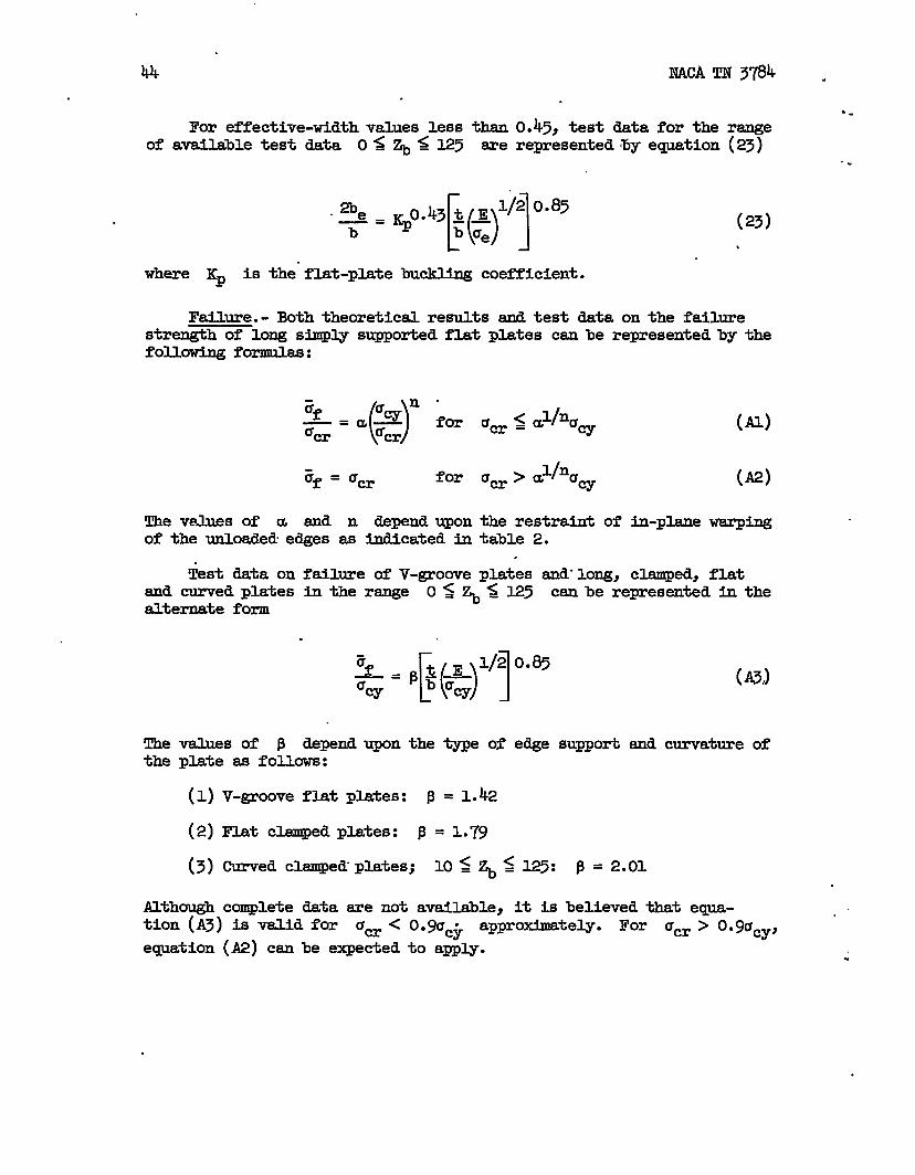
44 NACA TN 3784 .
For effective-widthvalues less than 0.45, test data for the range● .
of available test data OS ~ ~ 125 are represented by eqpation (23).
. 2be [()]43 t * l/20.85—= Kpo.b K<
(23)
,
where Kp is the”flat-plate buckling coefficient.
Failure.- Both theoretical results smd test data on the failurestrength of long simply supported flat plates can be represented by thefouawing formulas:
?if ()n-
‘%—=u#— for u= ~ ~l/nU% % w
l/nafor um>a ~
The vehes of a and n depend upon the restraint ofof the unloaded edges as indicated in table 2.
,
&st data on failure of V-grome plates and-long,and curved platesalternate form
Thethe
values of P
(Al)
(A2)
b-plane wsrping
clamped, flatin the range ‘OS ~S 125 can be-repres-ated in the
.
‘f [013./20.85—= $g~
‘w(5)
depend upon the type of edge support and curvature ofplate aa fol.lows:
(1)
(2)
(3)
Although
V-groove flat plates: P = 1.42
Flat clamped plates: ~ = 1.79
Curved clamped platesj loa@25: p=2.ol.
complete data me not avai~ble, it is believed that equa-tion (A3) is-valid for am < 0.9Uc~ approximately. For am ~ O.9ucy, “
eqyation (A2) can be expected to apply. .

NACA TN 3784 45.
,.
crippling
The generalized crippling analyses of test data indicate that, fora given material, the”crippling strength depends upon the developedlength-thicknessratio and the number of corners of the section:
(A4)
(45)
For formed sections, the additional.effects of the al.cladcoating andthe increased properties in the corners require consideration.
As shown in the section entitled “Crippling of Formed Angle, Z-,and Channel Sections,” the effects of the alclad coating canbe ade-gpately accounted for by use of the cladding reduction factor, as givenin equation (66): J
~ -1+ 3~C1/”cr)fl+sf
(66) .
This factor was derived in reference 3 and is bas~d on the bucklingstress of the section Ucr. Since the value of q affects equation (A4)in a relatively ndnor manner, only a rough estimate of am msybe
required in most applications.
The value of B in equation (A4) depends upon the increased yieldproperties 5CY in the corners of formed sections. As discussed in
the above-mentioned section and shown h figure 19, . ~ appears to be
proportional to (6cy,acy)[1-(m/2)J or (5cy,acy)[1-(m/3)]. This fOl-
10WS from equation (A4). Therefore, all values of ~ determined forone, two, and multicorner ekments are shown in figure 28 as a functionof 5
/Cy =Cy”
One-corner elements.- The available test data on formed angles andextruded-angle, T-, and cruciform sections are adequately representedby the following generalized cripplhg formula:
.
. . —-—. —--- —.— . —.—— - . —— .- .

46.
NACA TN 378h.
(A6)
Sections with opposed flanges appear to have greater cripplingstrengths than those with supported unloaded edges subjected to in-pl=e-m. This effect is discussed in the sections “Failure of Flanges,”“F&~e of Compressed FlatChsmnel, and H-Sections.”
Values of m and Bftable 13 and figure 28.
Equation (A6) is valid
angles for which ?icy/Cw >
that equation (A6) is valid
Plates,” and “Crippling of Ec&uded Z-,-
for use with equation (A6) are given in,
f‘r ‘-s ‘f ~f/ucy < 0“92 f‘r f‘-d1.25. Test data on cruciform indicate
f‘r ~f/%y < 3/4” ~ the absence of other
test data, this cutoff should be used for all other cases listed intable 13. Beyond the cutoff, equation (73) can be expected to apply:
(73)
Two-corner elements.- The availAble test data on formed and extrudedZ-, J-, and channel sections are represented by the following generalizedcripp~ formula (61):
(61)
Values of B are given in table 14 and figure 28. The rsmge of valldityof equation (61) fo~ows from equations (48) and (64):
(A7)
For an average value of P = 3.6, equation (A7) reduces to
~f <22
()
1/3—_ (A8)=Cy %
Beyond this cutoff value, equation (~) applies.
— .— --

7U NACA TN 3784 47
An H-extrusion is afor H-extrusions for the
\,
special type of two-corner element. Test datarange 18= ~/t ~ 23 are ti good agreement..
. with equation (31) for 6f/Ucr g 3/4:
.af = omoucro”%cyo”~
Beyond the cutoff, equation (~) [email protected].
Multicorner elements.- The available testtubes and formed sections of various shapes asall representedby
(30
data on extruded sqpareshown in figure 24 are
$=4!w1’70”8’Values of Pc are given in table l’jand figure 28. ~
The range of validity of equation (31) for square tubes is<0.7, as shown in figure 13.~f/ucy = FYomfigure 27, it appesrs that
a suitable cutoff for B= = 1.3 wwuldbe 6f/ucyS 0.9. There ace
insufficient test data to establish cutoff values for other values of
PC* However, for < 3/4, equation (~) probably is of sufficient3f/uw =
accuracy for most cases.
.
. .
-.. ..—-— -. —-- -- ———.. --— —-

.
48 NACA TN 3784.
REmmmEs---
1.
2.
4..
6.
7.
8.
99
10.
Il.
12.
Gerard, George: Handbook of Structural Stability. Part V - Compres-sive Strength of Flat Stiffened Panels. NACATN 3785, 1957.
.
Khbn, Paul, Peterson, James P., and Levin, L. Ross: A Summery ofDiagonal Tension. Part I - Methods of Analysis. NACA TN 2661,1952.
Gerard, George, and Becker, Herbert: Haudboak of Structural Sta-bility. Part I - Buckling of Flat Plates. NACA TN 3781, 1957.
Becker,Herbert: Handbook of Structural Stability. Part II -Buckling of Composite Elements. NACA TN 3782, 1957.
Gersrd, George, and Becker, Herbert: Handbook of Structural.Sta-bility. Part III - Buckling of Curved Plates and Shells. NACATN 3783, 1957.
Stowell, Elbridge Z.: Compressive Strength of Flanges. NM!ATN 2020, 1950.
Needhsm, Robert A.: The Ultimate Strength of Aluminum-Al@y FormedStructural Shapes h Compressio~. i@ur. Aero. Sci., vol. 21,no. 4, Apr. 1954, pp. 217-229.
Mevers,J., and Budians4, Bernerd: -is of Behavior of SimplySupported Flat Plates Compressed Beyond the Buckling bad into thePlastic Range. NACA TN 3368, 1955.
Argyris, J. H., and Dunne, P. C.: Structural Principles and Data.Pert 2, structural Analysis● Handbook of Aero., no. 1, fourtlied.,Sir Isaac Pitman & Sons, Ltd. (Iondon), 1952.
Anderson, Roger A., and Anderson, Melvin S.: Correlation of CripplingStrength of Plate”Structures with Material Properties. NACA
‘ TN 3600, 1956.
Botman, M.: De ~erimentele bepaling van de meedragende breedtevan vlakke platen h het elastische en het pl.astischegebied(deel II). (The lh@rimental Determination of the IYfective Widthof Flat Plates in the Elastic and Plastic Range (part 11).)Rep. S.438, Nationaal Iuchtvaartlaboratorium,.Jan. 1954.
Besseling, J. F.: De experimentele bepaling van de meedzagendebreedte van vlskke platen ti het elastische en het plastischegebied. (The I@erimental Determination of the Effective Widthof Flat Plates in the Elastic end Plastic Range.) Rep. S.414,Nationaal Lucht_laboratorium, Fyb..1953.
.

NACA TN 3784 49
b’
13.
.
14.
15.
16.
17.
18.
19.
20.
a.
22.
23.
24.
25*
26.
Cox, H. L., and Pribram, E.: The Elements of the Buckling of CurvedPlates. Jour. R.A.S., vol. 52, no. 453, Sept. 1948, ~. 551-565.
Cox, H. L., and Clenshaw, W. J.: Compression Tests on Curved Pauelsof Thin Sheet Duralumin. R. &M. No. 1894, British A.R.C., 1941.
Jackson, K. B., and Hall, A. H.: Curved Plates in Compression.Rep. AR-1, Nat. Res. Council, 1947.
Ievy, Samuel: Lsrge-Deflection Theory of Curved Sheet. NACATN 895, 1943.
Rauiberg,’Walter,Ievy, S~el, and Fienup, Kenneth L.: Effect ofCurvature on StrengthNACATN*944, 1944.
Sechler, Ernest E., and-is S@ Design.
of Axially Imded Sheet-Stringer Panels..
Dunn, Iouis G.: Airplane StructuralJohn Wiley & Sons, Inc., 1942.
Crockett, Harold B.: Predicting Stiffener and Stiffened PanelCrippling Stresses. Jour. Aero. Sci., vol. 9, no. 13, Nov. 1942,pp. 501-509.
Schuette, E. H.: Observations of the Maximm Average Stress ofFlat Plates Buckled in Edge Compression. WA w 1625, 194-9.
Heimerl, George J.: Deteriuinationof Plate Compressive Strengths.NACATN 1480, 1947.
Gerard, George: Secant Modulus Method for Determining Plate hsta-bility Above the Proportional Limit. Join,.Aero. Sci., vol. 13,no. 1, Jan. 1946, ~. 38-U, 48.
Heimerl, George J., and Roberts, William M.: Determination ofPlate Compressive Strengths at Elevated Temperatures. NACARep. 960, 1950. (Supersedes NACATN l&)6.)
Gallaher, George L.: Plate Compressive Strength of FS-lh Magnesium-Alloy Sheet and a Msximum-Strength Formula for Magnesium-Alloyand Aluminum-Alloy Formed Sections. NACATN 1714,1948.
Heimerl, George J., smdStren@hs of AircraftSheet. NACAWR L-20,
Heimerl, George J., andthe Strength of 24-S-T—
Roy, J. Albert: Column and Plate CompressiveStructural Materials. 17S-T Aluminum-Alloy1945. (Formerly NACAARR @08.)
Woods, Walter: Effect of Brake Forming onAluminum-AUoy Sheet. NACATN 1072, lg46.
—.— .— — —.. __ -- .. .. —.— — —. .—.

50 NACA TN 3784 -
-.
27. Woods, Walter, and Heimerl, George J.: Effect of Brske Forming inVarious Tempers on the Strength of Alclad 75S-T Aluminum-AlloySheet. WA~ u62, 1947.
.
28. Rauiberg,Walter, and kwy, Samuel: ~tability of Extrusions UnderCompressive Loads. Jour. Aero. Sci., vol. 12, no. 4, Oct. 1945,pp. 485-498.
29. Templin, R. L., Hartmam, E. C.j and Paul,,D. A.: Typical Tensileand ContpressiveStress-Strain Curves for Aluminum Alloy 24S-T,Alclad 24S-T, 24S-RT, end Alclad 24S-RT Products. Tech. PaperNo. 6, AluminumRes. Lab., Aluminum co. of Am., 1942.
30. Roy, J. Albert, and Schuette, EvanH.: The Effect of Angle of BendI!etweenPlate Elements on the Local ~tability o? FormedZ-Sections. NACAWR L-268, 194-4. (FormerlyNACARB L4126.)
31. Coan, J. M.: Large-Deflection Theory for Plates With Small InitialCurvature Ioaded in Edge Compression. Jour. Anl. Mech., vol. 18,no. 2, June 1951, pp. 143-151.
.
. . -.

51
●
!l?AxLEl.- VALUES OF~FQR
SIMPLY SUPPORTEDf-
mATPLATEs1
Unloaded edges Uhloaded edges “blat held straight, free lx?inovein plane
v= constant of plate, Uy=o
o 0.500 0.408
.25 .548 .458
●5 .580 .494.
1 .621 .540
2 .665 .590
4 .696 .613
w .746 .684
TABLE 2.- VALUESOF a AND n FOR FLAT PLATES
Element a n
Theory for straight unloaded edges 0.78 0.80
V-groove test data .80 .58
Three-bay plate test data .80 .65
.
..-— —— —.. — -— ——..-———- .. -—

52 NACA TN 3784 -
-.TAmE 3.- VALUESOF a AND n FOR VWOUS
EXTRUDED SECTIOMS AND WWERIUS .
.
Material
2014-T4
202h-Tk
R303-T
7075-~
o-1 HTA
I Values of a for -
H-section,n= 0.80 “
0.83
.80
.80
Z-section,n= 0.72
0.85
.81
.83
.80
.82
a.82
Channel section,n= 0.72
0.85
.81
.81
.79
●79
aAverage.
TABLE4.- CRIPEUNG OF FQRMED EQUAL FLANGE AMGIES
Material. c, Issi acy, ksi E, ksi
2024-T3 225.0 45.1 10,500
Alclad 2024-T3 200.1 “ 42.0 10,000
Alclad 7075-T6 259.0 66.2 10,000

NACATN 3784 53
TAELE 5.- VALUES OF a FOR CKEPLING
FoRMEDz—m~ SECTIONS
.
.
Material.
2017-T3
2024-T3
2024-T3
Fs-lh
Section
Z, channel
z
channel
z
(bw/t) ~v
25.531.7
18.823.126.731.938.7
24.529.534.243.2
2935
OF
a
0.85.82
.89
.87
.85●77.74
.87
.84
.80
.74
.81
.77
T4BLE6.- VALUES OF ~ M A FUNCTION (M’ bf~
FOR Z- AND CHANNEL SECTIONS
bf/% % %0”25 ~ + @f/%)]o”75
0.4 3.37 2.13.
.6 2.00 2.14
.8 1.25 2.17
.
.
.
-.. — ___ ___ .— —. — — —. ..-

54 NACA TN 3784.
.
-7.- INCREASEDCORNERl?ROl?ERTIES
lKIRIURMED SICTIONS
Sheet material i, in./
R/t 5CY acy
. 2017-v 0.I.25 3 1.23
2024-T3 .125 3 1.35
Alclad 7075-T6 .102 6. 1.06
Fs-lh - .102 4.3 1.15
TABLE8.- VARIATIONOF p WITH 6cy/acy ~R
Z- AND CHANNELSECTIONS
Material R[t/
3CY Ucy BI
P (zcypcy)314
2017-T3 3“ 1.23 4.00 3.42
2024-T3 3 1.35 4.00 3.19
Alclad 2024-T3 3 1.35 4.00 3.19
Alclad 7075-k 3 al.09 3.42 3.14
FS-lh 4.3 1.15 3.78 3.42
b3.30
AlleXkrusioIls (fi~eted) - l“m
3.64.
●aEsthtid Vd.lE .
bAverage value..
,.-
.

I
I
I
!r#!aLE9.- TEST DATA ON ~ mwm m T-sEcTIom
LIs shape. em from bt. of Cr.ckett (ref. 19); Ehapes 6 and Y are “from data of -rg ena L=V (ref. 28).]
()
1/2 “
~pe t, ml. bl, in. bz, in. Alti2 ~~ 3f, ksi/,
acy, ksi Zf Ucy
(a) , (b)
Chgle sectioris
L9208 0.125 “ 0.875 1.75 21 0.67 32.4 .43 0.754
Ls 209 .051 .~ .625 22 .70 30.7 43 .737
m 210 .125 l.co “ 1.75 22 ●P 32.8 43 .764
6 .064 l.cm 2.00 46.1 1.44 - ---- 42:4 ‘.43
cT-sectione
Ia 236 0.065 1.00 1.50. 38.5 0.82 . 31.0 43
‘LS 247 .040 .75 1.25 p 1.06 29.2 43
% 248 .Om 1.00 1.30 9 1.06 28.0 43
‘M 2@ .064 1,00 l.p s .83 32.2 43
7 .lm . 3.00 2.09 49.6 l..w ---- 40.4
aFor T_~eCtiO~, ~ iS total width d mw=d flues’. .
0.721
.W
.652
.750
‘.65
%br Crockett‘Sdata (ref. 19), Ucy = 43 k.eiae obtahd ~ [email protected], “Hdmann, ad Paul (ref. 2!3).
C= ~wion fimts for ~g~es ~O <R/t < 1/2; for T-sections,
1/2 < R/t <1.‘Values of ~ ~- /. correspond to L’/p = 20.
‘eThe bl flange had B l/16-in. -radius bulb at free edge.
I

56 NACA TN 3784 .
---
.
Shape
(a)
ElE2
:
X785-C
xIs-165
Is-160
Is-1a
. .
TABIE 10. - TEST nM!A ON‘IWO-CORNERImMEm!s.
t, in.
0.0252.0253.o~.0255
.025
.040
.064
.025
.040
.064
.025
.040
.025
.040
.025
.040
.025
.040
.025
.040:025.040
J&2
136.787.267.695.5
10364.540.310364.540.3
99.462.199A62.1
80.8509580.8!m.5
93.658.593.658.5
1/3
()
A ‘CY.—t2 *
22.10Ih.lo10.92~5.45
G.5210.686.93ti.671.1.477.45
15.9410.2817.U21.L02
;.;$
V1928.98
“15.039.6816.1510.40
iff, ksi
15.822.624.721.0
19;626.237.722.0
g:;
20.726.625.634.7
23.732.425.935*9
.21.5@*323.230.4
Crq, ksi
(b)
42424242
:;
415L
;:
41415151
41415151
41. 41
5151
Zf/cfcy
0.376.538.588.500
.478
.639
.920&n●X3.853
.505
.648
.502
.680
.578
.~o
.507
.704
.222
.715
.455
.596
%ee figure 22 for dimensions of sections.
bFor Crockett’s data (ref. 19), values of UW were obtained from
Tem-@in, Hartmam, and Paul (ref. 29).
.
.

NACA TN 3784 .
.
TABLE11.- D-IONS OF MUILl?ICORNERSECTIONS
[ 1See figure 24 for explanation of notation
57
.
-------------
Shape a, in. b, in. c, in. d, in. e, in. t, in. A/~2
!@ee-corner elements
Al i.000 1.000 0.434 0.434 ----- 0.0250 107.6A2 1.568 I.568 .437 .437 ----- .0315 u9.8.m 1.788 9953 .443 .438 ----- .o~o 67.2G1 ●977 1.561 .881 .422 ----- .0318 111.2G2 .936 2.457. .863 .425 ----- .0255 175.7
Four-corner elements .
c1 2.457 0.980 0.980 0:$++ 0.449 0.0200 247.0C2 2.487 .987 .987 .414 .0315 158.4C3 2.4I.2 .892 .892 .408 .408 .0382 W*7C4 2.236 1.262 I.262 .428 .428 .0505 1o4.1C5 I.813 .862 .862 .425 .425- .0258 157.0F1 2.331 .856 1.241 .424 .424 .0318 155.5F2 2.118 .976 I.266 .732 .442 .0318 163.7D1 1.231 2.260 .853 JA3 .443 .0203 239.0D2 1.255 2.195 .875 .429 .429 .0382 128.1D3 .847 1.887 .847 Ag 431 .0258 160.8D4 1.244 1.950 1.244 .423 .0252 198.5
I.250 1.904 1.250 .415 .415 .0383 1.27.1X7;;-D .625 I.250 ●7% -.--- ----- .025 167.5x785-D .625 1.250 “750 ----- ----- .040 1o4.7
Five-corner elements
H 3.668 1.528 0.393 0*943 ----- 0.0318 191.7B-152 2.500 1.312 .250 .562 ----- .040 126.5IS-153 3.250 1.437 .187 .562 ----- .051 101.6
Six-corner elements
B1 1.205 1.340 1.236 0.447‘- ----- 0.0255 282.0B2 L 198 1.610 1.001 .445 ----- .0320 199.5
.,
.-— -... —— . —- -—---- .-—

58 NACA TN 3784 .
..
.
TABLE 12.- TESTDAT/lON MULTICORNERSECTIDNS
1/2Shape ~
()
~ @cy ??f.,ksitscy,ksi
—— %lacy(a)
~2 ~(b)
. Al 3 7.30 26.2 42 0.624k 3 8.21 22.9 42 .545In 4.91 -35.0 .839G1 ? 7.32 26.2 & .624G2 3 u.56 17.8 42 .424
c1 6.25 17.3 .412C2 ; 10.42 24.1 & .574C3 8.46 27.5 42 .655C4 ! 7-% 31.4 42 .748C5 10.32 24.o .571F1 : 10.35 23.9 E .569F2 10.78 23.8 ●567D1 : 15.70 17.4 !: .41kD2 4 8.78 28.2 42 .671D3 10.58 23.3 “555D4 : 13.07 19.0 - & .452
4 “ 8.72 27”7 .659X7~-D “ 4 10,72 22.0” EX785-D :
●5377.03 31.1
X785-D.760
11.97 24.3 E .477x785-D 4 7.83 . 36.2 51 .710
H 5 13.00 25.0 42 3!3;“E-152 5 9*!X 39.5IS-153 5 7“75 44.1 ;: .864~
B1 6 19.15“ 20.8 42’ .495B2 6 13.70 27.1 42 .645
%ee figure 24 end tsble 11 for shapes and dimensions.
-..
-.
.
%or Crockett’s data (X78~D, IS-152, IS-153) (ref. 19), valuesof uCy were obta$ned from Templin, Hartmnn, and Paul (ref. 29)...
.
-. —.

NACA TN 3784
.
.
59
TABLE13.- OME-CORNERELIMENTS
Elanent “● m %yl~cy ~f Remarks
Formed sngles o.8~ 1.0 0.59L 1 s .621.2 .65 Estimated
. >1.25 .66
Extruded angles .85 ----- ..57 R/t = l/2 “----- “ .60 Estimated for
R/t = 1
T-extrusions .40 ----- .67 Based on 13mited’test data -
CrucifOlmlexlnllsions .40 ----- .67
TABIJI14.- TWO-CORNERELEMENTS
Element ~cy/%y.
P Remsrks
Formed angles 1.0 3.3 Estimated1.1 3.51.2 3.8
>1.25 4.0
Extruded sngles 3.6. R/t = 1
.
*.— — —.. .--

60
.
.
.
TABLE15.- MULTICORNEREIEMENIS
Elements %#cy Pc Regwks
Formed angles 1.0 1.1 Estimsted1.1 1.2 Estimated
>1.25 1.3
Extruded angles ----- 1.2 Estimsted forR/t = 1
EXruded squsre tubes ----- 1.4
.
.
. .
.

NACA TN 3784
.“
●
PLATES
Lo COLUMNS
%6&\
SONEM?YO FOINT OF FAILURE. ——— FLAS7MTY EEEECTS
- INITIAL IMWRFECTION ~ ‘W,
61
. .
WAVE DEPTH , ETh7CKNESS t
(a) Elastic buckling.
Lo
FLAT PLATES
.
- --WTIAL lMmcrloN = W?
o.
~AVE DEPTH , &m!!cmsss t
(b) Plastic buckling.
Figure 1.- Schematic postbuclilingbehavior of various axially compressedelements.
,
.
-— -.. . -..— ——— - —.—— —— —-—— ———. — —— -- -— —

\
●
✼
7EST DATA ●
%
.
k\.(
Figure 2.- Cmperlscm of theoretical failure analysis with test data on 2(324-9A aluurl.num-al.kwcruoiform sections and 2024-Tj fcmmed angles.
.
.
,
.
;

)U NACATN 3784 63
.
3
G
TEST DATA
F o ELASTIC
● PLAS TIC— THEORY
/ z 3
Figure 3.-
.
Cmparison of experimental data with theory forbehatior of hinged flsnge.
.
i
.
.-. .— .—..-. _ — —.— . ----

64 NACA TN 3704
. . .
.
/5
/0
5
Gx
ccr
o
.
-5 ~.5 /’42
suPPau7zo2X45
fREEEME EDSE
(a) Stradn distribution.
WPPORrEO FREEE@6E z/b E08&
(b) Stress distribution.
Figure 4.- Theoretical strain and stress distribution across a hingedf-e of ~24-T% ~uminuma~oy (~taframstowell, ref. 6).

.
NACA TN 3784 65.
.Q
u-V =constont
13
I1
/-Y
=0d.
(a) Straight unloaded edges.
Figure5.-
(b) Stress-freefree to warp
unloaded edgesin plane of
plate.
Stresses smd displacements of flat platesconditions of uniform end shortening (see
.
after buckling underref. 31).
. -.— -. . ______ __ —-- ..— . .. ..

66 NACA TN 3784
..
(Wt&.#E)%
2 3 4. 56 78910
“iii?. SOW m=O.85
■ 2W4- 76● 70Z?5-T6
-~%
\
A
‘1 THREE MY FLAZES-B07M4N
~ M4XERS-fW.MWVW T~
h , *
. V-GROOVE
RAZES 8 SQUARE7ZJ’BES
a b
—J 2 .3 .4 .6 .6 .7 &8 69W
97%..
. .
.
Figure 6.-Results of theoretical failure analysis of compressed flatplates with straight unloaded edges and test data on v=ious plateelements.
.

NACA TN 3784 67
20
, ff+b)’
/0
o
10
C8
.2
(a)Elasticpostbuckling behavior.
1 I 1 1
/0 20 30 40 t
Figure 7.- Data for long,
w~E(f/b)g(b) Hfective width.
,
clamped, curved plates. Nmibers indicate
of : = %(1 - ,2)-1’2.
values
.- . . ..— .— — — - .— _—. ..-. —— -—-. -...—.

f,,
.$
.6
.s
,.4
.3
2
J2 S 4 66789A7 m 40 mm 4?W 400 ~d
,

?.,
, 69
.4
.7
4
a.U
.4 I
\
\
-/0%
“P0s5 479
S25 ml
—
—
\
—
3%
Figure9.-
.
.
data on failure of lopg, clemped, flat and curvedplates.
.— .-— .— ..-— ——..—. —.- .—. —

-10
I
C& m~
(a) H-extrusions.
Figure M. - Crippllng data for varioue extrwlons.
9
!?“s

Ou NACA
.
*,
TN 3784
●
❉
71
(c) Channel extrusions.
Figure 10.- Concluded.
. . . .. . ... . . . ----- .—. —-— ,-- .—-- —.- — —— ——- -—---- —-

72 WA TM 3784 .
3/4cgw
STRESS
log(g)10 cr
CRIPPLING
PLASTIC BUCKLING
WPPMVG
CRR=LNG FVR CRIWMVS ~EtiSTIC SWKLIN6 PLASTIC
BUCKLfN6
N
‘A,CVTOFF
<
a/9
Figure 11. - Relation between buckling crippling of
.
extruded sections.
--
-..

I
i
I
}tI
Figure 12. - Ehort-tl.me crippling data on Eextru6iont3 at elevated
Data * reference ~.
temperatures.
)
I

NACA TM 3784
76
5
4
2
●OI
-.
.,
20
7060
50
F
40 “
Gs so
ksl
20
10,0
G@zz
90
Figure 13.- Crippling data on extruded tubes accofiing to various corre-lation methtis. b/h = 0.583; b/t = (b + h)/2t for rectangular tubes.

75
Figure 14.- Generalized crippling analysis of formed angles.
.43
7
.6
.5
2
./
\ .
k .
WTOFF
I %
-/0%
ALCLAD 7075-t6
T 2024-W EQLW AWES 451 ksl 085 0.6650 ALGLAD2024-Z3 @ It 420 0.85 0.6658 ALGLAD7075V!! JJ It 662 0.85 0.630● ALGLAD2U24.T3u~~~ n 420 0&5 0.665
.— --—-—— . . ... . . .-

:*
i
?4..
(a) Pomed 2- and channel sections of X)17-93 aluminum alloy.
Figure 15. - Crippling data on fonued sections.
:

7’7
,-
30
2.5
q/~
20
18
16
.-./ .2 .3 4 .5 6 .7 .8 .9 i
M
I
(’%/m n23/ a75
/2 : 3L9 .75
=/Icy
1A I I I I I I I I~
(h) Formed Z-sections of
Figure 15.-
2024-m sltmd.mmsJJ-oy.
Continued.
. . . .. . .. ——___ _ . — .——. —. —— —-— . . . .

78
-.
30
25
Z@W
2 .3 # .5 .67 .8.940
M I
.9 i
(c) Formed channel sections
Figure 15. -
%iiy
of 202k-m aluminum alloy.
Continued.
v

:.
— o
0
./
4’.AW n a 1“28 W 081
3S .n5 .77
I
.? -i
!2
(d) Fmmed Z-sections of l%lh magnesium ~. ,
l?lgure15.- Continued.
is

A/t=
4Ji5— w
(e) Formed Z- sad channel sections. Each circle representa three tests; size of circle indicates lascatter of data in each group. slope, m = 0.75:
-
Fltyre 15.- Ccmcl.uded. 8
;
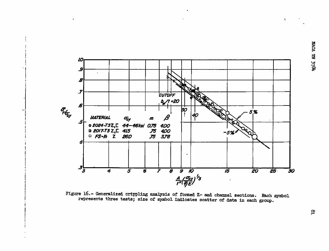
I
i
xl I I I I
40
.9\
.8 ‘1 N
.7
CU7VFF
.5, ff/t=20 ( ,=
Im
MA?ERIAL% mP- ‘ TY
s 0 Po#-r3z,E 44-48M am WO I❑ 4?OI%T3 Z,c 415 J15400Om-#)z aso
N233X8
-5%
d
33 4 5s7 89D 15 20 2’5 i
Figure 16.- Generdked crippling analysis of folmed Z- and chmnel sections. Each synibol
represeds three teats; size of symbol Indicates scatter of data in each group.
I
I

%’
\
. =
++
.8 \
=7\_
AU Z,K EXZRUSIOAfS
.6I1
M4ZERI!4L P
2024-T3 Z FVt?MED I
20iWT3 E u
2017-T3 Z , C “
I
4.05
fWh Z “
A// ~XtWShtiS Z ,C 3.64
-to 20 30 40 50 60 ?V8090D0
byY
i!
R@ure 17. - Variation of crippling coefficient with parameter ~/t. =
3
:

II
I
I
IiII
!I
i
d
I,
+@%)%Figure 18.. Generalized crippling enalysh of formed elclad channel eectiom.
\.
1?!a
HP
I

qI I
fo /./ /2 /.3 M
%y
Figure 19. - Variation Of generalized cripp~n,g coefficient with increaaed
corner properties.
,

i
.6
.2
k
● .
0
\
EXT)?~ED ANGLES FVRMED ANGLES
f
E o EXTRUDED ANGLES 065 CW65
~ ❑ -j- - sfJy/o~s .40 ●67V
Jru~- a%nom .40 .670
-— -
3
.5 .6 7.8.940 /!5 20 30 40 50
$@+Figure 20. - Generalized crippling analysis of fklgea
f, number of fknges.
8?
one-corner extruded 6ection9.

86NACA TN 3784
Ho I // I 1
y
?20° 40” 60e 8oe 100°
8/20°
AA@L~ OF BEND,
Figure 21. - Effect of bend sngles on buckling andZ-sections. L, length; material, 2024-!Fj
crippling of formedalundnum alloy.

2U ‘ NACA TN 3784
,
.87
,.
illb
to
R=3t
c
.
“1-+--lSOURCE’ AEHWAM WAPEE SOURCE’ CROCKETT X785-C
SWIPE ~in. o,h bin. c,h sin.
E“ 00252 L991 0653 0961 t?025m .0253 J032 492 AW4 .040E3 .0504 2Y41 .418 4228 .064E4 .(2?55 1213 .408 .935
t-w
t$in.
0D25.040
CROCKETTLS460
tyh.
0D25.040
l++
bin.
m2!5.040
Figure 22. - Dimensions of two-corner formed sections used for analysis.Nee-, reference 7; Crockett, reference 19.
,
. ..—. —-.— .— —. —. ——.. .— - ---- .

LoI
.9> .x \
\ m m mm-73 Z,c sEcnoNs”
.8\
10%h
*
MQZiFRIAL
ALCLAD 2024- T3
ALCLAD 2024-T3ALCLAD 2024- TWIAL&do 20M- T3ALcMD 2@4-T36
“ALtuo 2a?4-r3ALCLAD 2024- T36
AL&40 2t224-T3
ALCLAD 2G24- T36
t
EX?t?s-d
x=-o
ms”m
ta?M-MO
L$f61
M-w
]1
C&
4&oksi
41.0a o
4A o
61.0\
4L05L0
4/.0
W.o
2;I I I I I I I I I
456 789/0 /5 m 30
+(’*)k
Figure 23. - Generalhad crippling analysis of two-corner formed sectione.
.’ ;

89NACA TN 3784
$.
.
TG ~. ‘-~/VEWHAIW’ A4A2,F3 AEEVHAM’ 6/,62 “
4 CORNER EL~
NEEDHAM: NEEOHAM:CI-C5, FI,K2 DI-D5 X~-D
c
NEEOHAMt H Cmmrt’ Ls-/52
6 COWER EWHV%9 .Ls-i’63
~b~
Fa k+c’
●
Figure2h.- Multicornerformedsectionsused for analysis. Bendradius, R = 3t except as noted. Needhsm, reference 7; Crockett,reference 19. .
.
,.
. . . .. . .—-—. — ——. .— —. ——. .“” -— . . . . — ——. - .— --—

Esc$2-9
I I I I I I I I
l\ k
\ ,
\
6 \\
.3 — c.\
. .K!\}= —
I w 1> I I
~-CS FI I?2a-mxm-o P
\l \4
C53 I
16b B1 6s 60s
J23
1 1 t t I 1 I I I
+56 78910 E 20.
‘8
Figure 2S. - Ckmerallzed crippling emlysis of multicorner formed sections according to number of F
cornem. @en symbols, slclad 2024-T3 alloy; solid dynibols,alclad 2024-T36 alloy; F Indicates ~ .flange buckled first.
3
.

NACA TN 3784
<)
91
.
Figure26.-
.,
7
6
3
5
3
Variation of
74 5“
A/a of C’ornersz c
.
.
.
6
generalized crippling coefficient with numberof corners.
.---- _-. ——— ——— . —- .—-- .-—- ——- - - --—

.
Lol . I I I I
kc,
3Ah of Crews
3PP40 a&s
::d
.3 # .6 ,
)8
allal.YeisOfmul.ticornerfonlleaFigure 27.- Generalized crippling sections. open symbols, dcl~
wk-qs alloy;so-iid S@IOIE, alclad m24-!c36el.loy.3
. . ‘.

NAC!ATN 3784
.
93
,
.
w Kw?nE.R ELEb’&iv7s
(ANGLES)kOPE=060
1111x’7ws/o/vs-R!t=//2
+’HiWORMER ELEMENZS
bc3J~~~ra75
1111Ex7ws/oN’s-R/t=/
0 FVRMED SECTIONS— —.. — . .- —- --- —---- -, EX7??UOED
@l ESTIMATESEC7WWS
SECTIONSFOR EXTRUDEDOF R/t= I
I I I ~3-h6-WNER ELEMEN?l$—
WLWE=OS75
Figure 28.- Estimated variations ofvarious
NACA - Lmgleg Field, m.
. ..._ _.. ..— . .
generalized crippling coefficient forsections.
—- —— - —--—- —---.—- --