
National Remediation Framework · 2018-11-26 · ISCO In-Situ Chemical Oxidation MNA Monitored...
43
CRC for Contamination Assessment and Remediation of the Environment National Remediation Framework Technology guide: In-situ chemical oxidation Version 0.1: August 2018
Transcript of National Remediation Framework · 2018-11-26 · ISCO In-Situ Chemical Oxidation MNA Monitored...

CRC for Contamination Assessment and Remediation of the Environment
National Remediation Framework
Technology guide: In-situ chemical oxidation
Version 0.1: August 2018

CRC CARE National Remediation Framework Technology guide: In-situ chemical oxidation
Information correct at time of publication i Version 0.1: August 2018
National Remediation Framework
The following guideline is one component of the National Remediation Framework (NRF). The NRF was developed by the Cooperative Research Centre for Contamination Assessment and Remediation of the Environment (CRC CARE) to enable a nationally consistent approach to the remediation and management of contaminated sites. The NRF is compatible with the National Environment Protection (Assessment of Site Contamination) Measure (ASC NEPM).
The NRF has been designed to assist the contaminated land practitioner undertaking a remediation project, and assumes the reader has a basic understanding of site contamination assessment and remediation principles. The NRF provides the underlying context, philosophy and principles for the remediation and management of contaminated sites in Australia. Importantly it provides general guidance based on best practice, as well as links to further information to assist with remediation planning, implementation, review, and long-term management.
This guidance is intended to be utilised by stakeholders within the contaminated sites industry, including site owners, proponents of works, contaminated land professionals, local councils, regulators, and the community.
The NRF is intended to be consistent with local jurisdictional requirements, including State, Territory and Commonwealth legislation and existing guidance. To this end, the NRF is not prescriptive. It is important that practitioners are familiar with local legislation and regulations and note that the NRF does not supersede regulatory requirements.
The NRF has three main components that represent the general stages of a remediation project, noting that the remediation steps may often require an iterative approach. The stages are:
• Define; • Design and implement; and • Finalise.
The flowchart overleaf provides an indication of how the various NRF guidelines fit within the stages outlined above, and also indicates that some guidelines are relevant throughout the remediation and management process.
It is assumed that the reader is familiar with the ASC NEPM and will consult other CRC CARE guidelines included within the NRF. This guideline is not intended to provide the sole or primary source of information.

CRC CARE National Remediation Framework Technology guide: In-situ chemical oxidation
Information correct at time of publication ii Version 0.1: August 2018

CRC CARE National Remediation Framework Technology guide: In-situ chemical oxidation
Information correct at time of publication iii Version 0.1: August 2018
Executive summary
ISCO involves the injection of a chemical oxidant into the ground for the purpose of transforming groundwater or soil contaminants into less harmful chemical products, such as carbon dioxide, water and inorganic chloride. There may be many chemical reaction steps required to complete this transformation, and the design of the oxidant delivery system (ensuring the contaminants enter the aqueous phase) and optimisation of the dose (for the oxidant and activator/solvent/surfactant where relevant) is important in facilitating the necessary reactions and in achieving the remediation objectives.
The most commonly used oxidants for ISCO include:
• Potassium permanganate
• Hydrogen peroxide (including Fentons reagent)
• Ozone
• Sodium Persulphate
Treatability studies can be undertaken to determine the most efficient oxidants to remediate the contaminants in the soil or groundwater.
The breadth of groundwater contaminants amenable to transformation via various oxidants is large, with a wide range of contaminant classes amenable to chemical oxidative treatment. These include:
• Highly amenable contaminants:
- Chloroethenes
- Chlorobenzenes
- Benzene, toluene, ethylbenzene and xylene (BTEX)
- Petroleum hydrocarbons
- Polycyclic Aromatic Hydrocarbons (PAHs)
- Phenols (cresols, chlorophenols, nitrophenols)
- Fuel oxygenates (methyl tertiary butyl ether (MTBE))
- Alcohols
- 1-4-dioxane
• Potentially amenable contaminants:
- Chloroethanes
- Chlorinated or brominated methanes
- Explosives
- Herbicides and pesticides
- N-Nitrosodimethylamine (NDMA)
- Ketones
- Polychlorinated biphenyls (PCBs)
- Dioxins/furans

CRC CARE National Remediation Framework Technology guide: In-situ chemical oxidation
Information correct at time of publication iv Version 0.1: August 2018
Three critical success factors in all ISCO projects are:
• The effective mobilisation of contaminants from the soil into the aqueous phase.
• The effective distribution of the reagents in the treatment zone.
• The reactivity of an oxidant with the contamination present.
ISCO is becoming an important component of many remediation strategies where it is used to rapidly reduce contaminant concentrations in soil and groundwater, or to reduce the mass of contaminant.
ISCO has traditionally been viewed as a stand-alone treatment technology for achieving remediation objectives at many sites where the time factor and the nature of contamination require an aggressive, rapid approach over that which can be achieved through natural degradation. However, ISCO technologies can also prove useful as part of a sequential or more complex remedial approach. ISCO can be enhanced using surfactants and co-solvents; this is known as surfactant-enhanced ISCO, or S-ISCO®.

CRC CARE National Remediation Framework Technology guide: In-situ chemical oxidation
Information correct at time of publication v Version 0.1: August 2018
Abbreviations
BTEX Benzene, Toluene, Ethylbenzene and Xylene
CB Chlorinated Benzenes
CHP Catalysed Hydrogen Peroxide
COCs Contaminant of Concern
CRC CARE Cooperative Research Centre for Contamination Assessment and Remediation of the Environment
CVOCs Chlorinated Volatile Organic Compound
DCA Dichloroethane
DCE Dichloroethene
DO Dissolved Oxygen
FOC Fraction of Organic Carbon
HASP Health and Safety Plan
ISCO In-Situ Chemical Oxidation
MNA Monitored Natural Attenuation
MPE Multi-Phase Extraction
MTBE Methyl Tertiary Butyl Ether
NAPL Non-Aqueous Phase Liquid
NDMA N-Nitrosodimethylamine
NOD Natural Oxidant Demand
NRF National Remediation Framework
OHS Occupational Health and Safety
PAHs Polycyclic Aromatic Hydrocarbons
PCB Polychlorinated Biphenyl
PCE Tetrachloroethylene
PPE Personal Protective Equipment
RAP Remediation Action Plan
SEAR Surfactant Enhanced Aquifer Remediation
SEPRTM Surfactant Enhanced Product Recovery
S-ISCO® Surfactant Enhanced In-Situ Chemical Oxidation
SVE Soil Vapour Extraction
TCA 1,1,1-Trichloroethane
TCE Trichloroethylene

CRC CARE National Remediation Framework Technology guide: In-situ chemical oxidation
Information correct at time of publication vi Version 0.1: August 2018
VC Vinyl Chloride

CRC CARE National Remediation Framework Technology guide: In-situ chemical oxidation
Information correct at time of publication vii Version 0.1: August 2018
Glossary
Activator A chemical that is used to initiate or speed up a chemical process, as a catalyst does, but that is consumed by the chemical reaction.
Aquifer
An underground layer comprising bedrock, unconsolidated natural material, or fill, that is capable of being permeated permanently or intermittently with groundwater, and that allows the free passage of groundwater through its pore spaces.
Catalyst A substance that speeds up a chemical reaction, but is not consumed by the reaction.
Concentration The amount of material or agent dissolved or contained in unit quantity in a given medium or system.
Conceptual site model
A representation of site-related information including the environmental setting, geological, hydrogeological and soil characteristics together with the nature and distribution of contaminants. Contamination sources, exposure pathways and potentially affected receptors are identified. Presentation is usually graphical or tabular with accompanying explanatory text.
Contaminant Any chemical existing in the environment above background levels and representing, or potentially representing, an adverse health or environment risk.
Contaminated site
A site that is affected by substances that occur at concentrations above background or local levels and which are likely to pose an immediate or long-term risk to human health and/or the environment. It is not necessary for the boundaries of the contaminated site to correspond to the legal ownership boundaries.
Contamination
The presence of a substance at a concentration above background or local levels that represents, or potentially represents, a risk to human health and/or the environment.
Co-solvent A chemical added to increase the solubility and mobility of the contaminant solvent, in order to increase the efficiency of remediation.
Daylighting Transport of fluids, ordinarily contaminants or contaminated groundwater, to the ground surface
Dosing The volume of treatment chemicals required to remediate a certain volume of groundwater
Environment(al) protection authority / agency
The government agency in each state or territory that has responsibility for the enforcement of various
CRC CARE National Remediation Framework Technology guide: In-situ chemical oxidation
Information correct at time of publication viii Version 0.1: August 2018
jurisdictional environmental legislation, including some regulation of contaminated land.
Groundwater Water stored in the pores and crevices of the material below the land surface, including soil, rock and fill material.
In-situ chemical oxidation
The injection of a chemical oxidant into the ground for the purpose of transforming groundwater or soil contaminants into less harmful chemical products, such as carbon dioxide, water and inorganic chloride
Kinetics The branch of physics that explains motion, force and torque
Oxidant A chemical that oxidises other substances, causing them to loose electrons.
Practitioner Those in the private sector professionally engaged in the assessment, remediation or management of site contamination.
Proponent A person who is legally authorised to make decisions about a site. The proponent may be a site owner or occupier or their representative.
Reagent A substance that takes part in and undergoes change during a chemical reaction.
Redox This is short for reduction / oxidation, and describes a chemical reaction in which electrons are transferred between chemicals.
Remediation
An action designed to deliberately break the source-pathway-receptor linkage in order to reduce the risk to human health and/or the environment to an acceptable level.
Risk
The probability that in a certain timeframe an adverse outcome will occur in a person, a group of people, plants, animals and/or the ecology of a specified area that is exposed to a particular dose or concentration of a specified substance, i.e. it depends on both the level of toxicity of the substance and the level of exposure. ‘Risk’ differs from ‘hazard’ primarily because risk considers probability.
Site
A parcel of land (including ground and surface water) being assessed for contamination, as identified on a map by parameters including Lot and Plan number(s) and street address. It is not necessary for the site boundary to correspond to the Lot and Plan boundary, however it commonly does.

CRC CARE National Remediation Framework Technology guide: In-situ chemical oxidation
Information correct at time of publication ix Version 0.1: August 2018
Smear zone The area where hydrocarbons in the soil have been smeared across the soil as the water table has fluctuated between historic high and low elevations.
Solvent
A chemical that is able to dissolve other substances. Solvent contaminants include a range of hydrocarbons used in industrial processes due to their dissolving properties.
Sorbed The process by which one substance becomes attached to another substance. This may occur through adsorption or absorption.
Surfactant A substance that chemically bonds to both oils and water, and transfers oils into the aqueous phase where they are more readily remediated.
Thermodynamics The branch of physics concerned with the relationship between heat, temperature, energy and work
Treatability studies A series of tests designed to ascertain the suitability of the treatment for the contaminants under the site conditions

CRC CARE National Remediation Framework Technology guide: In-situ chemical oxidation
Information correct at time of publication x Version 0.1: August 2018
Measurements
Unit or symbol Expansion
mg/L milligram per litre
Chemical symbols, formulae and abbreviations
Symbol or abbreviation Meaning or expansion
CaO2 Calcium peroxide
CH2Cl2 Dichloromethane
(also known as methylene chloride)
CHCl3 Chloroform
CO2 Carbon dioxide
Fe(II) Ferrous oxide, FeO
Fe(III) Ferric oxide, Fe2O3
H2O2 Hydrogen peroxide
KMnO4 Potassium permanganate
MgO2 Magnesium peroxide
MnO2 Manganese dioxide
MnO4- Permanganate ion
Na2CO3•3H2O2 Sodium percarbonate
NaMnO4 Sodium permanganate
O- Superoxide ion
O2 Oxygen
OH- Hydroxyl ion
SO42- Sulfate ion

CRC CARE National Remediation Framework Technology guide: In-situ chemical oxidation
Information correct at time of publication xi Version 0.1: August 2018
Table of contents
National remediation framework i
Executive summary iii
Abbreviations v
Glossary vii
Measurements x
Chemical symbols, formulae and abbreviations x
1. Introduction 1
2. Technology description and application 1
3. Feasibility assessment 4
3.1 Data requirements 7
3.2 Treatable contaminants 9
4. Treatability studies 14
4.1 Bench tests 14
4.2 Pilot trials 15
5. Design 18
5.1 Integration of ISCO with other technologies 18
6. Validation 22
7. Health and safety 23
Appendix A – Oxidants 26
Appendix B – Case studies 30
Appendix C – References 31

CRC CARE National Remediation Framework Technology guide: In-situ chemical oxidation
Information correct at time of publication 1 Version 0.1: August 2018
1. Introduction
The purpose of this guideline is to provide information on in-situ chemical oxidation (ISCO) as a treatment technology for the remediation of contaminated sites to assist with selection of remediation options. The document contains information to inform remediation planning and aid compilation of a remediation action plan (RAP).
This guidance is primarily intended to be utilised by remediation practitioners and those reviewing practitioner’s work, however it can be utilised by other stakeholders within the contaminated sites industry, including site owners, proponents of works, and the community.
ISCO is one of many technologies available for contamination remediation, and other technologies may be more appropriate. It is assumed that the information presented within will be used in a remediation options assessment to identify and select the preferred technologies for more detailed evaluation. This guideline provides information for both initial options screening and more detailed technology evaluation. This guideline does not provide detailed information on the design of ISCO systems as this is a complex undertaking and should be carried out by appropriately qualified and experienced practitioners. In addition, the application of surfactant-enhanced ISCO (S-ISCO®) is proprietary and is covered by an international patent.
Readers are directed to the NRF Guideline on performing remediation options assessment for detailed advice on assessing remediation options. In addition, the remediation objectives, particularly the required quality of the soil after treatment, are a critical matter and it is assumed that these have been determined and considered in the remediation options assessment and selection process. Readers are directed to the NRF Guideline on establishing remediation objectives for more detailed advice.
References to case studies are provided in Appendix A.
A number of sources of information were reviewed during the formulation of this document to compile information on potential technologies. These are listed in references, and provide an important resource to readers.

CRC CARE National Remediation Framework Technology guide: In-situ chemical oxidation
Information correct at time of publication 2 Version 0.1: August 2018
2. Technology description and application
ISCO involves the introduction of a chemical oxidant into the subsurface to transform groundwater and/or soil contaminants into less harmful chemical substances, such as carbon dioxide, water and inorganic chloride. There may be many chemical reaction steps required to complete this transformation; however, with suitable characterisation, design and implementation, the reactions may proceed rapidly to completion.
ISCO relies on kinetics, thermodynamics and stoichiometry in determining whether an oxidant will react with site contaminants. These are dependent on many variables including:
• Temperature;
• pH;
• Concentration of the reagents;
• Catalysts;
• Mobilisation of the contaminants;
• Reaction by-products; and
• System impurities.
An additional factor is the delivery of the oxidant – for effective degradation of the contaminated material the oxidant must encounter the contaminant. Ideally, the oxidant will be dispersed evenly across the entire area requiring remediation. However, strong oxidants, which are required to treat more stable contaminants, can be consumed quickly in the subsurface, limiting the distance they can travel.
The implementation of ISCO requires careful site characterisation, screening and feasibility testing. Failure to mobilise and treat contaminants can result in a continuing source of groundwater contamination, and multiple ISCO injection events can be required. Subsurface heterogeneities or preferential flow paths can cause an uneven distribution of the oxidant, resulting in pockets of untreated contaminants. The remediation design must account for the residual, adsorbed and dissolved phase contamination to achieve effective site remediation.
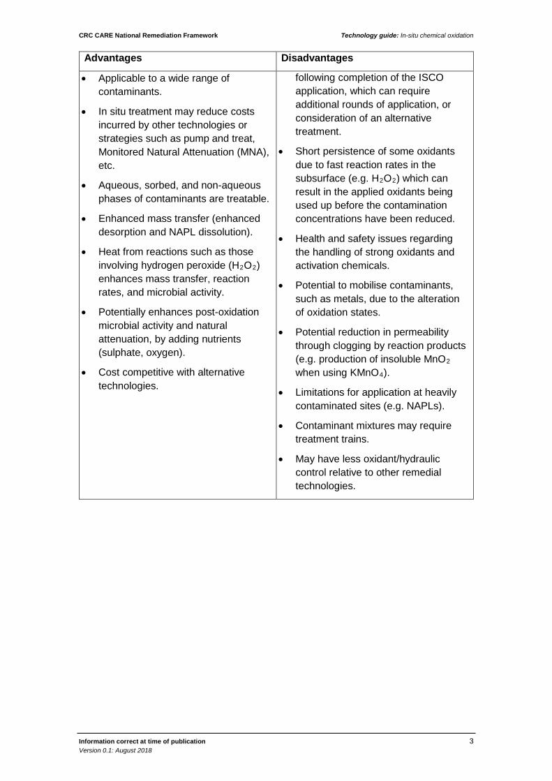
The advantages and disadvantages of ISCO are summarised in Table 1 below.
Table 1: Advantages and disadvantages of ISCO
Advantages Disadvantages
• Large volumes of waste material are not usually produced.
• Treatment can occur over a shorter timeframe due to the fast destruction of contaminants.
• Destroys contaminants in situ, without having to excavate material or pump out groundwater for aboveground treatment.
• Potential difficulty in delivering oxidant to all areas of contamination due to reactive transport and aquifer heterogeneities.
• Natural oxidant demand (NOD) may be high in some soil/aquifers.
• Contaminant concentrations can rebound (return to original or unacceptable concentrations)
CRC CARE National Remediation Framework Technology guide: In-situ chemical oxidation
Information correct at time of publication 3 Version 0.1: August 2018
Advantages Disadvantages
• Applicable to a wide range of contaminants.
• In situ treatment may reduce costs incurred by other technologies or strategies such as pump and treat, Monitored Natural Attenuation (MNA), etc.
• Aqueous, sorbed, and non-aqueous phases of contaminants are treatable.
• Enhanced mass transfer (enhanced desorption and NAPL dissolution).
• Heat from reactions such as those involving hydrogen peroxide (H2O2) enhances mass transfer, reaction rates, and microbial activity.
• Potentially enhances post-oxidation microbial activity and natural attenuation, by adding nutrients (sulphate, oxygen).
• Cost competitive with alternative technologies.
following completion of the ISCO application, which can require additional rounds of application, or consideration of an alternative treatment.
• Short persistence of some oxidants due to fast reaction rates in the subsurface (e.g. H2O2) which can result in the applied oxidants being used up before the contamination concentrations have been reduced.
• Health and safety issues regarding the handling of strong oxidants and activation chemicals.
• Potential to mobilise contaminants, such as metals, due to the alteration of oxidation states.
• Potential reduction in permeability through clogging by reaction products (e.g. production of insoluble MnO2 when using KMnO4).
• Limitations for application at heavily contaminated sites (e.g. NAPLs).
• Contaminant mixtures may require treatment trains.
• May have less oxidant/hydraulic control relative to other remedial technologies.

CRC CARE National Remediation Framework Technology guide: In-situ chemical oxidation
Information correct at time of publication 4 Version 0.1: August 2018
3. Feasibility assessment
Key site-specific considerations that will often determine the feasibility of ISCO as a potential remediation option include whether the:
• Physical form and concentration of the contaminant is such that it can be effectively degraded;
• Residual (including residual contamination, reagent, byproducts including volatile gases, and mobilised metals) will meet the requirements for future use of the groundwater and land;
• Contaminant concentrations will rebound and, if so, the response that will be required;
• Extent and distribution of contamination is sufficiently well known to effectively target the treatment;
• Uniformity and permeability of the geology allows delivery of the reagent to the entire mass of contaminant;
• Area affected by the treatment can be contained and the area of adverse effect is not expanded.
This section provides general information on carrying out a more detailed assessment of the application of ISCO. There are a number of published documents that are useful in providing more detail on the assessment process and undertaking treatability studies, and the reader is encouraged to refer to the literature provided in the reference section at the end of this guide. Two key reference documents are USEPA (2004) and ITRC (2005).
The ISCO remediation evaluation process can be divided into four steps as described in Table 2.
Table 2: ISCO evaluation process
Step Description
Step 1 An initial screening of chemical oxidation effectiveness to provide a quick determination of whether chemical oxidation should be considered as a remedial approach for the site
Step 2 A detailed evaluation of chemical oxidation effectiveness to provide further screening criteria to confirm whether chemical oxidation is likely to be effective. This detailed evaluation includes site-specific data on the nature/extent of contamination, potential risk to human health/the environment, subsurface geology and hydrogeology, and other relevant site characteristics
Step 3 An evaluation of the chemical oxidation system design in the corrective action plan to determine whether basic design information has been defined, necessary design components have been specified, the construction process flow designs are consistent with standard practice, and adequate feasibility testing has been performed.

CRC CARE National Remediation Framework Technology guide: In-situ chemical oxidation
Information correct at time of publication 5 Version 0.1: August 2018
Step Description
Step 4 An evaluation of the operation and monitoring plans to determine whether baseline, start-up and long-term system operation and monitoring are of sufficient scope and frequency and whether remedial progress monitoring and contingency plans are appropriate.
Figure 3 is a flowchart showing the decision steps involved with an initial screening of ISCO, which is based on:
• The presence of excessive oxidant demand;
• Soil permeability; and
• Proximity to buried structures which may be damaged by strong oxidants

CRC CARE National Remediation Framework Technology guide: In-situ chemical oxidation
Information correct at time of publication 6 Version 0.1: August 2018
Figure 1: Initial screening for potential effectiveness of ISCO, from US EPA (2004)

CRC CARE National Remediation Framework Technology guide: In-situ chemical oxidation
Information correct at time of publication 7 Version 0.1: August 2018
3.1 Data requirements If the initial screening is successful, then a detailed screening should be carried out. A recent and comprehensive ISCO screening tool was developed by SERDP (2010), which considers the site-specific factors outlined in Table 3.
Table 3: ISCO screening tool considering site-specific factors, from SERDP (2010).
Factor Detail to consider
Oxidant type • Amenability of primary contaminants of concern (COCs) to oxidation
• Amenability of co-contaminants to oxidation
• Overall Oxidant Amenability
• Ability of approach to work with site fraction organic carbon (FOC)
• Ability of approach to work with site pH
• Ability of approach to work with site alkalinity
• Ability of approach to work with site chloride
• Ability of approach to work with site COC mass distribution
Implementation (injection) methods
• Amenability to site media type
• Amenability of delivery technique to site hydraulic conductivity
• Amenability to site heterogeneity
• Ability to reach depth of contamination
• Ability to treat contaminant density
• Disruption of site surface activities
• Disruption of subsurface activities
The oxidants and activators considered
• Permanganate
• Ozone (including ozone only, and ozone activated with peroxide)
• Hydrogen peroxide (including Iron/acid activation, chelated iron activation, no activation (mineral catalysis))
• Percarbonate
• Persulphate (including alkaline activation, thermal activation, iron / acid activation, chelated activation, peroxide activation, no activation (mineral catalysis))

CRC CARE National Remediation Framework Technology guide: In-situ chemical oxidation
Information correct at time of publication 8 Version 0.1: August 2018
Factor Detail to consider
The injection methods considered
• Direct-push probe injection
• Vertical injection wells
• Horizontal wells
• Vertical wells – recirculation
• Soil mixing
• Hydraulic fracture emplaced ISCO amendment
• Pneumatic fracture emplaced ISCO amendment
• Trench or curtain injection
• Surface application / infiltration gallery
The SERDP ISCO Screening Tool is an MS Excel-based spreadsheet and available on CD upon request from SERDP website.

CRC CARE National Remediation Framework Technology guide: In-situ chemical oxidation
Information correct at time of publication 9 Version 0.1: August 2018
Figure 2 is based on the USEPA (2004) decision tree for detailed screening of ISCO:
Figure 2 Detailed Screening of ISCO effectiveness
3.2 Treatable contaminants A wide range of contaminants can be amenable to transformation by oxidants. Three critical success factors in ISCO projects are the:
• Effective mobilisation of contaminants from the soil into the aqueous phase;
REVIEW KEY SITE INFORMATION- Permeability- Heterogeneity- Carbonate Geology (eg limestone)- Natural organic material / soil oxidant demand
Treatment zone permeability > 10-4 cm/s?
Homogenoustreatment zone?
Non-carbonategeology?
SOD not >> contaminant
oxidant demand?
Trial Successful ?
Trial Successful?
Trial Successful?
Economicevaluation OK?
Conduct pilot permeability enhancement trial (eg fracturing, mixing or others) to improve potential for oxidant delivery
and contact with contaminants
Conduct pilot trial to demostrate oxidant can be delivered to and is effective on contaminant in low K layers and lenses
Peroxide and Ozone Oxidants OnlyConduct pilot trial to demonstrate
effective contaminant destruction under elevated pH conditions
Complete economic evaluation and verify cost effectiveness of ISCO solution
ISCO IS LIKELY TO BE EFFECTIVE AT THE SITE.
PROCEED TO EVALUATE THE SYSTEM DESIGN
STOPISCO IS UNLIKELY TO BEEFFECTIVE AT THE SITE
AND / OR MAY BE UNSAFE TO IMPLEMENT
NO
NO
NO
NO
NO
NO
NO
NO
YES
YES
YES
YESYES
YES
YES
YES

CRC CARE National Remediation Framework Technology guide: In-situ chemical oxidation
Information correct at time of publication 10 Version 0.1: August 2018
• Effective distribution of the reagents in the treatment zone; and
• Reactivity of the selected oxidant with the contamination present.
Table 4 summarises the general applicability of ISCO in relation to different contamination phases.
Table 4: General applicability of ISCO, from ITRC (2005).
Nature of contaminant ISCO Applicable? Considerations
Mobile NAPL:
Continuous NAPL pools
Possible, but challenging Co-solvent/surfactant or very high oxidant dose required
Residual NAPL:
Discontinuous NAPL globules
Yes, but challenging Co-solvent/surfactant or high oxidant dose
High groundwater concentrations:
>10 mg/L
Yes, a good fit Standard
Low groundwater concentrations:
<1 mg/L
Yes, but may not be cost effective
Cost driven by matrix oxidant demand and size of plume
The presence of residual phase NAPL and high dissolved concentrations in the source area can present a challenge, however, ISCO can be generally applicable if it recognised that a co-solvent/surfactant substrate or high oxidant dose will be required, or that other ISCO variants may be required such as S-ISCO® (a combination of co-solvents and surfactants with ISCO). With the latter technology, the co-solvent and surfactants are able to mobilise NAPL by partitioning into the solvent allowing greater contact of NAPL and subsequently better contact with the oxidant. Multiple injections may be required due to rebound.
The performance of oxidants is often poor when there is:
• Poor characterisation that underestimates/misses the amount or does not identify the location of contamination, resulting in an inadequate volume of substrate;
• Poor uniformity of oxidant delivery caused by site heterogeneity and low-permeability zones; or
• Excessive oxidant depletion by natural organic materials (NOM) or by the presence of high concentrations of contaminant.
Figure 2 illustrates the influence of contaminant phase and mass transfer limitations on the mass and number of oxidant applications likely to be required for ISCO.

CRC CARE National Remediation Framework Technology guide: In-situ chemical oxidation
Information correct at time of publication 11 Version 0.1: August 2018
Figure 3: Impact of contaminant phases, mass transfer, and mass transport limitations on the mass of oxidant and/or the number of oxidant applications needed for ISCO.
Contaminants amenable to treatment by ISCO include the following:
• Highly amenable contaminants:
- Chloroethenes
- Chlorobenzenes
- Benzene, toluene, ethylbenzene and xylene (BTEX)
- Petroleum hydrocarbons
- Polycyclic aromatic hydrocarbons (PAHs)
- Phenols (cresols, chlorophenols, nitrophenols)
- Fuel oxygenates (methyl tertiary butyl ether (MTBE))
- Alcohols
- 1-4-dioxane
• Potentially amenable contaminants:
- Chloroethanes
- Chlorinated or brominated methanes
- Explosives
- Herbicides and pesticides
- N-Nitrosodimethylamine (NDMA)
- Ketones
- Polychlorinated biphenyls (PCBs)

CRC CARE National Remediation Framework Technology guide: In-situ chemical oxidation
Information correct at time of publication 12 Version 0.1: August 2018
- Dioxins/furans
Table 5 summarises the reactivity of different types of oxidants with commonly encountered contaminants.
As all oxidants are nonselective, they also oxidise natural organic matter which is present in soil. Since organic contaminants can sorb to organic matter in the soil matrix, they can be released once the organic matter is oxidised.
Table 5: Reactivity of oxidants with common contaminants, from ITRC (2005).
Oxidant High Moderate Low
Ozone
• PCE,
• TCE,
• DCE,
• VC,
• MTBE,
• CB,
• PAHs,
• Phenols,
• PCBs,
• Pesticides
• BTEX,
• Dichloromethane (CH2Cl2)
• Chloroform (CHCl3)
Hydrogen Peroxide1
• PCE,
• TCE,
• DCE,
• VC,
• BTEX,
• MTBE,
• Phenols
• DCA,
• Dichloromethane (CH2Cl2)
• PAHs,
• TCA,
• Chloroform (CHCl3),
• PCBs,
• Pesticides
Calcium Peroxide
• PCE,
• TCE,
• DCE,
• VC,
• CB
• DCA,
• Dichloromethane (CH2Cl2)
• Chloroform (CHCl3)

CRC CARE National Remediation Framework Technology guide: In-situ chemical oxidation
Information correct at time of publication 13 Version 0.1: August 2018
Oxidant High Moderate Low
Fenton’s Reagent
• PCE,
• TCE,
• DCE,
• VC,
• CB,
• BTEX,
• MTBE,
• Phenols
• DCA,
• Dichloromethane (CH2Cl2)
• PAHs,
• TCA,
• Chloroform (CHCl3),
• PCBs,
• Pesticides
Potassium/Sodium Permanganate
• PCE,
• TCE,
• DCE,
• VC,
• TEX,
• PAHs,
• Phenols,
• Pesticides
• DCA,
• Dichloromethane (CH2Cl2)
• TCA,
• CB,
• Chloroform (CHCl3)
• PCBs
Sodium persulphate (Iron)
• PCE,
• TCE,
• DCE,
• VC,
• BTEX,
• Phenols
• DCA,
• Dichloromethane (CH2Cl2)
• Chloroform (CHCl3),
• PAHs,
• Explosives,
• Pesticides
• TCA,
• PCBs
Sodium persulphate (Heat, Peroxides and High pH)
• All CVOCs,
• BTEX,
• MTBE,
• PAHs,
• Phenols,
• PCBs,
• Pesticides,
• TPH
1. Peroxide without a catalyst must be applied at higher concentrations, which are inherently hazardous, and the reactions are more difficult to predict and control

CRC CARE National Remediation Framework Technology guide: In-situ chemical oxidation
Information correct at time of publication 14 Version 0.1: August 2018
4. Treatability studies
While ISCO screening assists with identifying viable oxidants and appropriate oxidant activation approaches, determining effectiveness is a site-specific undertaking. It may be necessary to compare or optimise approaches using soil or groundwater from the specific site in tests to improve design certainty and treatment effectiveness. If the detailed screening outcome is favourable, the next step is to conduct treatability studies, which generally are based on:
• Laboratory trials, using contaminated media (soil, groundwater)
• Pilot field trials
4.1 Bench tests For most ISCO applications, laboratory-scale testing is performed to optimise substrate dosing to improve the chances of success for full-scale implementation. Laboratory-scale testing is used to quantify treatment efficiencies of chemical oxidants with specific contaminants in both saturated soil and the dissolved phase. It can also be used to evaluate the oxidant demand of the soil matrix and the potential for mobilisation of metals in cases where soil metals concentrations are high. Laboratory trials also enable assessment of additional reaction processes which can occur for sites with NAPL or sorbed phase contaminant, co-contaminants, or potential for reaction by-products or intermediates that may be of concern. These processes affect contaminant destruction efficiency and effectiveness, and include:
• Oxidant activation optimisation (critical to CHP and persulphate oxidants).
• NAPL dissolution.
• Contaminant desorption.
• Impact of co-contaminants on contaminant dissolution, desorption, and destruction and the associated reaction rates.
The results of laboratory-scale testing of an ISCO technology may or may not be directly applied to the design of a pilot field trial. Laboratory scale results are often based on very small volumes of disturbed soil and/or groundwater relative to the actual volume that requires treatment. The test apparatus often does not adequately recreate the geometric nature or flow characteristics of the physical system observed in the field.
For example, one-dimensional columns and two-dimensional batch reactors are often used as convenient means to simulate the three-dimensional environment. Test boundary conditions that are not present in the field can become important in the laboratory test. Also, laboratory-scale tests often are based on well-mixed static systems, while the field implementation involves more heterogeneous flow. At the site scale, lithological heterogeneity implies a similar degree of heterogeneity of the oxidant demands, since oxidant demand is primarily a function of geochemical properties of the soil, including organic carbon content and the presence of reduced mineral phases (ITRC, 2005).
Treatability studies also allow remedial costs and technology efficiency to be better determined. Designing the treatability study may require input from a number of technical specialists including environmental specialists, chemical engineers,

CRC CARE National Remediation Framework Technology guide: In-situ chemical oxidation
Information correct at time of publication 15 Version 0.1: August 2018
mechanical engineers and air quality specialists to ensure that the study is targeted to obtain the data required to enable the most appropriate implementation strategy to be developed. The key objectives of an ISCO laboratory trial should include the following (SERDP, 2010):
• Optimisation of oxidation chemistry (this may involve testing of at least three different oxidant doses on the site-specific contaminants).
• Testing the contaminant destruction (and other) effects of different oxidant / activation chemicals, such as caustic soda, iron, temperature etc.
• Testing for oxidant / activator persistence.
• Comparison of results and selection of optimised oxidant / activator combination.
The SERDP ICSO Screening Tool contains detailed discussions and procedures for conducting laboratory trials.
4.2 Pilot trials Pilot studies provide the necessary information to perform a full-scale design, including determining appropriate injection well/point spacing and determining appropriate injection flow rates for liquid and/or gas delivery and to compare various oxidation approaches. Pilot test objectives should be developed based site-specific conditions and the need to reduce uncertainty. Possible objectives of a pilot test include:
• Evaluation of possible treatment effectiveness (i.e. mass removal or achievable concentration reductions) to reduce the uncertainty in the full-scale performance.
• Evaluation of reagent distribution and the zone of influence.
• Refinement of input parameters for the design tool (i.e. design parameters) to help reduce the uncertainty in the design and cost.
• Identification/troubleshooting of challenges on a smaller scale at lower cost.
• Evaluation of the potential for fatal flaws that would make ISCO impractical for full-scale application.
• Achievement of some initial mass removal.
• Characterisation of the resulting groundwater quality, and whether it is likely to meet relevant criteria.
Pilot testing is also performed to determine injection parameters required for system design, such as injection rates, temperature, pressures, and injection volumes.
The pilot field trials involve full-scale remediation performed on a small area of the site. Before performing any pilot-scale testing, it is important that all stakeholders have a realistic expectation of how the pilot-scale test results will be used to support full-scale remediation design. General technical considerations that should be addressed in planning for pilot scale testing of ISCO technologies are:
• Perform the on-site pilot test in a location that is most representative of site conditions. This is normally a smaller contaminated portion of the site in an area that will allow for uninterrupted operation. If the entire plume will not be treated in the pilot test, it is important to choose a cross hydraulic gradient

CRC CARE National Remediation Framework Technology guide: In-situ chemical oxidation
Information correct at time of publication 16 Version 0.1: August 2018
portion of the contaminant plume, if practical, to ensure that treated areas will not be re-contaminated and to enable observation of unaffected down hydraulic gradient areas.
• Design an oxidant injection program using existing wells, new injection wells, direct-push injection points, or a combination thereof. Appropriate spacing and alignment of injection points (i.e. grid formation) is important. To ensure uniform oxidant delivery throughout the contaminated zone, the zones of influence of all injection points should overlap. The amount of oxidant delivery should be determined by analysing the amount of contaminant mass and soil oxidant demand.
• Design a groundwater monitoring network with wells in the vicinity of each injection point. Monitoring wells must be located near and down hydraulic gradient of each injection point, so additional temporary monitoring wells may need to be installed. The monitoring wells should be located at differing distances from the injection points so that dispersion of the oxidant can be tracked and adequate monitoring data can be collected. At a minimum the perimeter of the contaminant plume must be monitored to ensure no off-site migration of oxidant and/or contamination.
• If there is a risk that oxidant and/or contamination might migrate off-site, consideration should be given to providing for hydraulic containment (e.g. downgradient interception wells).
• Establish a field monitoring and sampling program that will adequately monitor both the dispersion of the oxidant and the effectiveness of the treatment in three dimensions (refer Figure 5). Usually field measurements concerning oxidant dispersion (e.g. water table mounding, dissolved oxygen (DO), redox, pH, temperature) are conducted more frequently than contaminant analysis.
• For gas injection systems, pilot testing should be performed to substantiate the gas-phase influence area around an injection point. This can be performed by evaluating pressure influence, DO increases, helium tracing, water table mounding, and concentration dispersion of the injected gas.
• For liquid-injection systems, the pilot test should substantiate the dispersion of the solution into groundwater (and should be performed separate from any gas-injection testing) to ensure that there is an appropriate influence area at varying injection flow rates. As mentioned above, this can be done by measuring for pressure influence, DO increases, water table mounding, or concentration of the injected fluid.
Both laboratory tests and pilot studies are valuable tools for determining the mass of oxidant necessary to adequately remediate a site. In most cases (except for fractured rock), the oxidant demand of the soil matrix will exceed the stoichiometric demand of the contamination present and therefore it is essential to include this variable in the design process.

CRC CARE National Remediation Framework Technology guide: In-situ chemical oxidation
Information correct at time of publication 17 Version 0.1: August 2018
Figure 4: Possible pilot trial monitoring network layout, from SERDP (2010).
There are several potential pitfalls to be aware of when conducting ISCO field trials. These can include:
• The potential for contaminants to flow into the treatment area from untreated up gradient areas. This potential may be significant in highly permeable sites with significant contamination up gradient. This potential may be managed by locating the trial across gradient from the up-gradient source.
• The potential for the oxidant to persist in the formation beyond the time available for the pilot test, so that true endpoint concentrations cannot be obtained. The true end-point concentrations should be obtained after time is allowed for the oxidant to dissipate, the subsurface to re-equilibrate and return to ambient geochemical conditions, and for rebound (if any) to occur.
• The potential for the water added as part of the oxidant injected to dilute the in-situ contaminant concentrations temporarily. This dilution is especially challenging when most of the contaminant mass is in a dissolved state.
• Some oxidants cause significant desorption and dissolution of sorbed or residual NAPL. This desorption and dissolution may cause a temporary increase in the aqueous phase concentration observed in groundwater samples and may mask mass removal that is occurring.
• The potential for the resulting groundwater quality to not meet relevant criteria, such as may occur with solubilised metals, pH, reagent constituents (manganese, sodium, sulphate), and the need to be able to confirm that such excursions are temporary, and the final quality will be acceptable.

CRC CARE National Remediation Framework Technology guide: In-situ chemical oxidation
Information correct at time of publication 18 Version 0.1: August 2018
5. Design
There are many different variations of ISCO systems, depending on the delivery method and selected oxidant / activator combination. The following is an example listing of specifications and drawings that may be included for detailed design of an ISCO treatment system using a direct injection approach for potassium permanganate (SERDP, 2010).
• Civil
- Layout Plan (site boundary, access routes, locations of wells, equipment, storage areas, construction lay-down areas)
- Well construction diagrams
- Miscellaneous civil details (well vaults, trenches, concrete pads, fencing, bollards)
• Process & instrumentation
- Process flow diagram (oxidant and activator mixing, conveyance, and delivery equipment)
- Piping and instrumentation diagram (oxidant and activator mixing, conveyance, and delivery equipment)
• Mechanical
- General arrangement plans (control building; mixing, conveyance, and delivery equipment)
- Well vault layouts and sections
- Storage tank details
- Miscellaneous mechanical details (pipes, supports, spill containment)
• Electrical
- Single line diagram
- Power plan and schedules
5.1 Integration of ISCO with other technologies Historically, ISCO has been viewed as a stand-alone treatment technology for achieving remediation objectives at many sites where the time factor and the nature of contamination require a more aggressive, rapid approach.
ISCO technologies however can also prove useful as integral parts of sequential or more complex remedial approaches. This trend is being driven by a variety of site-specific concerns involving one or more of the following:
• Complex mixtures of contaminants and/or intermingled plumes;
• The presence of NAPL;
• Geological, hydrogeological and geochemical limitations; and
• Facility constraints such as ease of access and wellhead protection concerns.

CRC CARE National Remediation Framework Technology guide: In-situ chemical oxidation
Information correct at time of publication 19 Version 0.1: August 2018
ISCO is becoming increasingly used as a component of many remediation strategies to reduce high concentrations of contaminants in soil and groundwater or to destroy remnant NAPL (by for example, by applying surfactant-enhanced ISCO, or S-ISCO®).
The combination of technologies potentially allows ISCO to be targeted to areas with high concentration, and other longer term and generally less costly technologies to treat zones of lower concentration outside the area treated by ISCO or the contamination resulting after ISCO treatment. Under some circumstances ISCO has been found to enhance mass transfer from soil to groundwater by breaking down natural organic matter (and sorption sites) or increasing temperature, which can result in a more complete remediation of a site because both soil sources and groundwater contamination are removed or destroyed.
The major improvements in the overall effectiveness of remedial designs when integrating ISCO involve supplementing traditional mass transfer (pump and treat, air sparging/soil vapour extraction (SVE), dual-phase extraction) and/or monitored natural attenuation (MNA) technology applications.
ISCO is often coupled with these other remediation technologies as part of the overall treatment approach. Considerations for enhancing the coupling approach and/or cautions to consider in ISCO design and implementation are provided in Table 6.

CRC CARE National Remediation Framework Technology guide: In-situ chemical oxidation
Information correct at time of publication 20 Version 0.1: August 2018
Table 6 Considerations relating to the application of mass reduction processes before ISCO treatment, from SERDP (2010)
Pre-ISCO Mass Reduction Technology
Advantages Disadvantages
Excavation • Rapid implementation
• Easy to apply oxidant at the infiltration surface
• Soil mixing approaches may be more easily implemented
• Hotspots may remain
• Preferential flow may occur through backfill
• Contaminated or highly organic backfill may cause excessive oxidant demand
• Oxidant treatment of clean backfill represents inefficient oxidant use
Enhanced NAPL recovery / multiphase extraction (MPE)
• Removal of pooled or high NAPL saturation zones improves advective oxidant transport and likelihood of the success of ISCO
• Smear zone thicknesses may be increased
• Residual NAPL will likely remain
Surfactant-enhanced product recovery (SEPRTM)
• Surfactants and co-solvent substrates may improve the mobilisation of NAPL and residual mass
• Enhanced solubilisation and desorption may occur improving overall effectiveness by reducing the mass that requires oxidation
• Incompatible surfactants may cause excessive oxidant decomposition and can polymerise contaminant mass
• Some NAPL mass is likely to remain after SEPR and additional solvent will require oxidation
• Potential lack of control of mobilised contaminants
Surfactant-enhanced aquifer remediation (SEAR)
• Surfactants and co-solvent substrates may improve the reactivity of some oxidants
• Enhanced solubilisation and desorption may occur improving oxidation efficiency in the aqueous phase
• Incompatible surfactants may cause excessive oxidant decomposition and can polymerise contaminant mass
• Gas evolution may cause foaming and permeability loss
• Some NAPL mass is likely to remain after SEAR
• Potential lack of control of mobilised contaminants

CRC CARE National Remediation Framework Technology guide: In-situ chemical oxidation
Information correct at time of publication 21 Version 0.1: August 2018
Pre-ISCO Mass Reduction Technology
Advantages Disadvantages
Soil vapour extraction / air sparging
• Infrastructure may already be in place for in situ ozonation
• Contaminated vapours may be captured when using oxidants that evolve significant amounts of gas
• May oxidise some reduced minerals, lowering the soil's natural oxidant demand for ISCO
• Desaturated groundwater zones may have lower relative permeability, challenging uniform delivery of aqueous oxidants
Thermal remediation • Elevated temperature may effectively activate some oxidants
• For some oxidants and resistant contaminants, rates of degradation may be greatly improved at elevated temperature
• Elevated temperatures may pose health and safety concerns for some oxidants and contaminants with exothermic reactions
• Solidification of silt and clay materials may occur challenging subsequent oxidant delivery
• At elevated temperature, excessive oxidant decomposition may challenge effective delivery
Intrinsic or enhanced bioremediation
• Biological degradation processes (if any) may be anticipated to return to baseline (e.g., unamended natural levels) after ISCO, and these may be used as a polishing step
•
• Reducing conditions associated with anaerobic conditions may require excessive oxidant dosing
• Elevated biomass and/or organic substrate concentrations in the treatment zone may cause excessive competition for oxidant

CRC CARE National Remediation Framework Technology guide: In-situ chemical oxidation
Information correct at time of publication 22 Version 0.1: August 2018
6. Validation
The following information describes the specific validation appropriate for ISCO, to assist validation planning within the RAP. Readers are directed to the NRF Guideline on validation and closure, which among other things, provides further information on each of the lines of evidence.
The primary lines of evidence for in-situ chemical treatment are:
• A reduction in contaminant concentration over time or with distance through the reactive zone;
• An assessment of the mass discharge from treated materials; and
• The analysis of geochemical and biochemical parameters,
For more details on validating in-situ chemical approaches readers are directed to ITRC (2004).
As chemical treatment introduces chemicals and their reaction products into the subsurface (e.g. permanganate to MnO2), these should be monitored, including any potentially toxic and/or mobile transformation products. It is noted that where chemicals are injected into the ground for the purposes of remediation, regulatory approval may be required from the relevant jurisdictional agency. Some oxidative and reductive processes can have additional desired (and often intended) and undesired biodegradative and subsidiary chemical side processes, e.g. mobilising chromium when treating arsenic in groundwater, or oxidation and the production of perfluorinated alkylated substances such as perfluorooctanesulfonic acid (PFOS) from precursor substances. Monitoring should also consider clogging of the aquifer by precipitation of inorganic by-products (eg following injection of oils).
In the chemical treatment of soils, spatial variation in soil permeability will typically result in the flushing solution not contacting all the contaminated media. Validation of this technique should therefore comprise groundwater sampling to determine whether sufficient contaminant mass has been destroyed or recovered to meet remedial objectives. Core sampling of soil in areas with lower permeability can be an effective validation technique for this remedial method. This is because it can assess residual concentrations in areas where the technique may not have been successful in recovering impacted groundwater or free product from the subsurface (ITRC 2004).

CRC CARE National Remediation Framework Technology guide: In-situ chemical oxidation
Information correct at time of publication 23 Version 0.1: August 2018
7. Health and safety
ISCO remediation projects can expose site workers to health and safety hazards Common health and safety hazards associated with ISCO are highlighted in Table 7, along with possible control methods. The identified hazards are intended to serve as a general list, with variations from site to site. A detailed hazard assessment should be undertaken at every site where ISCO is intended to be implemented, which should be documented in the RAP. Many of these matters will be subject to regulatory control measures, and relevant national and state regulations should be referred to.
Readers are directed to the NRF Guideline on health and safety for further information on health and safety on remediation sites, including risk assessment, the hierarchy of controls and suggested documentation

CRC CARE National Remediation Framework Technology guide: In-situ chemical oxidation
Information correct at time of publication 24 Version 0.1: August 2018
Table 7 Common ISCO hazards and controls
Hazard Sources of exposure Suggested controls
Exposure to chemicals (oxidants)
• Dermal contact, vapour or dust inhalation.
• Use of appropriate personal protective equipment (PPE) including gloves, glasses and protective clothing.
• Chemicals should be stored appropriately and safely
• Readily available eyewash / shower (in case of dermal or eye contact).
• Read & understand material safety datasheets (MSDS) prior to materials handling.
Storage of hydrogen peroxide
• Hydrogen peroxide in concentrated form is explosive and can result in fire
• The design of systems needs to follow accepted codes of practice.
The presence and generation of ozone
• Increases in the flammability of many materials.
• The generation of ozone can involve high-voltage-equipment concerns.
• Potential for uncontrolled exothermic reactions
• Ensure oxidants compatibility with equipment and materials.
• Store and protect oxidants away from heat/cold & sun/rain as appropriate and in compliance with relevant dangerous goods regulations).
Ergonomic Risks • Lifting or performing any other movement with too much force and/or in an awkward position or repeating the lift/movement too often.
• Provide conveniently located equipment for the job, like correctly sized tools.
• Train workers on ergonomic risks and prevention.

CRC CARE National Remediation Framework Technology guide: In-situ chemical oxidation
Information correct at time of publication 25 Version 0.1: August 2018
Hazard Sources of exposure Suggested controls
Slips, Trips and Falls
• Storing construction materials or other unnecessary items on walkways and in work areas.
• Creating and/or using wet, muddy, sloping, or otherwise irregular walkways and work surfaces.
• Constructing and/or using improper walkways, stairs, or landings or damaging these surfaces.
• Creating and/or using uneven terrain in and around work areas.
• Working from elevated work surfaces and ladders.
• Using damaged steps into vehicles.
• Keep walking and working areas free of debris, tools, etc.
• Keep walking and working areas as clean and dry as possible.
• Perform a Job Hazard Analysis.
• Ensure use of PPE, including fall arrest systems.
• Train workers on fall hazards and use of ladders.
• Use an observer (spotter or signal person) when visibility is limited.

CRC CARE National Remediation Framework Technology guide: In-situ chemical oxidation
Information correct at time of publication 26 Version 0.1: August 2018
Appendix A – Oxidants
The most commonly used oxidants for ISCO include:
• Potassium permanganate
• Hydrogen peroxide (including catalysed hydrogen peroxide (CHP))
• Ozone
• Sodium Persulphate
The following sections provide brief descriptions of each of the above oxidants.
Types of oxidants Permanganate
Permanganate is available either as potassium permanganate (KMnO4) or sodium permanganate (NaMnO4). Both have similar reactivity; however, the potassium form is used more often as it is more soluble. KMnO4 is a crystalline solid from which aqueous solutions of varying concentrations can be made using groundwater or reticulated water supply. NaMnO4 is usually in the form of a concentrated liquid which is then diluted on-site.
Considerations in the application of potassium permanganate include:
• The oxidation potential (see table 3) of potassium permanganate (1.7 volts) is too low to oxidise benzene (2.00 volts), and hence may not be applicable to petroleum sites.
• Depending on the pH and whether the aquifer conditions are oxidising, the reaction of permanganate can lead to the formation of insoluble manganese dioxide (MnO2), which can reduce aquifer permeability. Excess permanganate creates oxidising conditions and this can result in the formation of MnO2 and, because of this, excess permanganate should be avoided and the quantity introduced should be well balanced with subsurface oxidisable material.
• Permanganate is persistent, and able to maintain reactivity in the subsurface for months.
• Soluble manganese in groundwater can be a toxicant, and it should be confirmed that the resulting groundwater quality will be acceptable.
Hydrogen peroxide (including catalysed hydrogen peroxide)
At low concentrations, hydrogen peroxide is not a sufficiently strong oxidant to degrade many hazardous organic contaminants. A large increase in the oxidative strength can occur in the presence of a transition metal such as iron or copper – iron catalysed hydrogen peroxide (CHP) is called Fenton’s reagent. The catalysis generates hydroxyl radicals which are very reactive.
Concentrated solutions of hydrogen peroxide and iron in an acid solution are usually injected using separate injection strings or nozzles. In some cases, however, iron may be present in the subsurface in sufficient concentration that eliminates the need for

CRC CARE National Remediation Framework Technology guide: In-situ chemical oxidation
Information correct at time of publication 27 Version 0.1: August 2018
further iron injection. The reaction can generate considerable heat and gas in the form of O2 and CO2.
Fe(II) and Fe(III) are consumed in a side reaction with hydroxide ions under alkaline oxidising conditions, forming ferric hydroxide. Because of this, it is necessary to either lower the pH or use chelating agents to maximise the available Fe(II). The hydroxyl radical is unstable and decomposes very quickly in the subsurface. Thus it can only be transported over short distances and has a radius of influence limited to only a few metres.
Rapid decomposition of hydrogen peroxide should be avoided during ISCO applications when using it as an oxidant, solvent or activator. Rapid decomposition results in the formation of oxygen, and can waste chemicals but, more importantly, has the potential to lead to daylighting (transport of fluids to the surface), lifting of concrete or asphalt, and the creation of an explosive atmosphere.
Ozone
There are two different forms of ozone application:
• Injection of ozone gas into the unsaturated zone and ozone sparging below the water table.
• Injection of ozone dissolved in water.
Ozone is highly reactive but it has a very short half-life and needs to be generated close to the treatment site. Unlike other oxidants, ozone injection requires a semi-permanent remediation system, including corrosion resistant piping and injection points.
Direct oxidation involves the oxidation of the target contaminant by ozone. This process has been widely used in water treatment to treat very low concentrations of contaminants. Indirect oxidation involves the creation of hydroxyl radicals from the parent oxidiser, ozone. This form of oxidation is a faster reaction than direct oxidation by ozone itself.
When ozone is applied to groundwater sources, it is commonly delivered via sparging screens with very small orifices which maximises mass transfer. Due to its gaseous nature, ozone can easily be used to remediate unsaturated zone contamination. As an added benefit, upon decomposition, ozone provides an additional source of oxygen which can enhance aerobic biodegradation processes. Longer injection times may be involved compared to other oxidants.
Ozone has the advantage of reducing to non-toxic end products (oxygen and water) and will not result in groundwater contamination. However, it is relatively costly and is unlikely to be applicable to contaminants that are present in high concentration (such as NAPL).
Persulphate
Persulphate oxidises most contaminants (particularly when activated) and is relatively persistent in the subsurface. The most commonly used version is sodium persulphate which is much more soluble than other forms. Persulphate salts dissociate in water to persulphate anions which are strong oxidants and react slowly to destroy many organic contaminants.

CRC CARE National Remediation Framework Technology guide: In-situ chemical oxidation
Information correct at time of publication 28 Version 0.1: August 2018
Persulphate is activated by one of four methods: transition metals (typically iron), high pH, heat or peroxides (often hydrogen peroxide) to produce sulphate radicals which are highly reactive with a rapid reaction rate. Iron is also involved in terminating reactions and is thus important in controlling reaction rates.
Applying temperatures above 40oC will also generate sulphate radicals. This has the added benefit of thermally degrading volatile organic compounds (VOCs) which reduces the amount of persulphate required and decreases the added cost of heating.
As sodium persulphate dissociates in water, persulfuric acid is generated and a temporary pH decrease occurs. The pH decrease can cause dissolved metal concentrations to increase in the groundwater, though this can be alleviated by the natural soil buffering capacity, or by adding high pH chemicals (e.g. caustic soda).
Activating persulphate with hydrogen peroxide, in addition to producing sulphate radicals, has the added advantage of invoking the solvent-like properties of hydrogen peroxide to assist with mobilisation. The decrease in pH by the activation of sodium persulfate can catalyse the hydrogen peroxide to further oxidise contaminant mass.
The application of persulphate as the sodium salt can lead to an increase in the concentration of sodium sulphate in the groundwater; this may exceed the criteria for use of groundwater and needs to be considered.
Oxygen-supplying peroxides (solids)
These include calcium peroxide (CaO2), magnesium peroxide (MgO2), and sodium percarbonate (Na2CO3•3H2O2). In general, they are used to supply oxygen to the subsurface to enhance aerobic biodegradation and so are not classified as oxidants per se, except for sodium percarbonate that releases hydrogen peroxide.
Oxidant strength Chemical oxidation technology is based on the oxidative power of specific chemicals. Some oxidants are stronger than others and it is common to calculate a relative strength for all oxidants using chlorine as a reference. Table 8 summarises the strength of oxidants commonly used for ISCO.
Table 8 Oxidant strengths
Chemical species Standard oxidation potential (volts)
Relative strength (chlorine = 1)
Hydroxyl radical (OH-)* 2.8 2.0
Sulphate radical (SO42-)* 2.5 1.8
Ozone 2.1 1.5
Sodium persulphate 2.0 1.5
Hydrogen peroxide 1.8 1.3
Permanganate (Na/K) 1.7 1.2
Chlorine 1.4 1.0
Oxygen 1.2 0.9
Superoxide ion (O-)* -2.4 -1.8
* these radicals can be formed when ozone and peroxide decompose

CRC CARE National Remediation Framework Technology guide: In-situ chemical oxidation
Information correct at time of publication 29 Version 0.1: August 2018
The radical species have the highest oxidative strengths and for this reason oxidants are often activated or catalysed with other substances such as iron or bases, or are heat activated, to form these radicals.
Table 4 identifies some additional considerations for in situ chemical oxidation treatment. Site-specific information is always needed for effective field application.
Table 9: Additional considerations for in-situ treatment with different oxidants, from ITRC (2005).
Consideration Peroxide Ozone Permanganate Persulphate
Unsaturated Zone Treatment
Successful Successful Successful Successful
Potential Detrimental Effects
Gas evolution, heat generation, by-products, resolubilisation of metals
Gas evolution, heat generation, by-products, resolubilisation of metals
By-products, resolubilisation of metals, concentrations of manganese that are detrimental to groundwater use
By-products, resolubilisation of metals, concentrations of salts (eg sodium and sulphate) that are detrimental to groundwater use
pH/Alkalinity Effective over wide range of pH, but carbonate alkalinity must be accounted for
Effective over wide range of pH, but carbonate alkalinity must be accounted for
Effective over a wide range of pH
Effective over wide range of pH, but carbonate alkalinity must be accounted for
Persistence Easily degraded in contact with soil/groundwater unless inhibitors are used
Easily degraded in contact with soil/groundwater
Oxidant is very stable
Oxidant is very stable
Oxidant Demand
Total oxidant demand (TOD) varies with soil. Contaminant oxidant demand is based on total mass and mass distribution (sorbed, dissolved, free-phase)
Soil permeability and heterogeneity
Low permeability soils and subsurface heterogeneity present challenges for oxidant injection and extraction

CRC CARE National Remediation Framework Technology guide: In-situ chemical oxidation
Information correct at time of publication 30 Version 0.1: August 2018
Appendix B – Case studies
Several remediation projects involving ISCO have been completed in Australia. Presentations on the following projects have been completed at Ecoforum Conferences and should be available from the Australasian Land and Groundwater Associated (ALGA):
• Croydon Park, SA – treated LNAPL and dissolved phase petroleum in soil and groundwater using hydrogen peroxide activated sodium persulfate ISCO (Ecoforum, 2012 presentation)
• Kilsyth, Vic – treated dissolved phase petroleum hydrocarbons in soil and groundwater using surfactant enhanced (mixed in place) ISCO (Ecoforum, 2012 presentation)
• Tweed Heads, NSW - Treated dissolved phase petroleum in soil and groundwater using surfactant enhanced, alkaline activated sodium persulfate ISCO (Ecoforum, 2012 presentation)
Additional Australian case studies include:
• Mann, B (2013): In Situ Chemical Oxidation (ISCO) and Enhanced in Situ Biodegradation (EISB) of Dissolved Benzene Plume Using High pH Activated Persulphate. Paper presented at Cleanup 2013 Conference, Melbourne Australia
• http://www.barangaroo.nsw.gov.au/media/72748/revised_work_plan_sept_2011_brrp46.pdf
The following international case study documents can be found at:
http://www.clu-in.org/techfocus/default.focus/sec/In_Situ_Oxidation/cat/Application/
Critical Analysis of the Field-Scale Application of In Situ Chemical Oxidation for the Remediation of Contaminated Groundwater (Krembs, Friedrich J.), Master's thesis, Colorado School of Mines, 226 pp, 2008 [supported by SERDP/ESTCP]. This thesis creates a database from 242 ISCO sites. The thesis analyses trends for the sites and allows for interactive activity with the user.
• Federal Remediation Technologies In Situ Treatment at Three Dry Cleaner Sites, Various Locations (2004) [ozone (1) and modified Fenton's reagent (2)].
• In Situ Chemical Oxidation at Two Drycleaner Sites, Hutchinson, Kansas and Jacksonville, Florida (2003) [ozone (1) and hydrogen peroxide (1)].
• In Situ Chemical Oxidation at Six Drycleaner Sites, Various Locations (2001, 2002) [permanganate (3), peroxide (2), ozone (1)].
Roundtable Cost and Performance Case Studies:
• Field Applications of In Situ Remediation Technologies: Chemical Oxidation. EPA 542-R-98-008, 1998. Describes pilot demonstrations and full-scale applications that either treat soil and ground water in place or increase the solubility and mobility of contaminants to improve their removal by other remediation technologies.

CRC CARE National Remediation Framework Technology guide: In-situ chemical oxidation
Information correct at time of publication 31 Version 0.1: August 2018
Appendix C – References
ITRC, 2001, Technical and regulatory guidance for in situ chemical oxidation of contaminated soil and groundwater, 1st ed. ISCO-1, Interstate Technology and Regulatory Council, In Situ Chemical Oxidation Team, Washington, D.C.
ITRC, 2005, Technical and regulatory guidance for in situ chemical oxidation of contaminated soil and groundwater, 2nd ed. ISCO-2, Interstate Technical and Regulatory Council, In Situ Chemical Oxidation Team, Washington, D.C.
NAVFAC, 2015, Design considerations for in situ chemical oxidation, Technical Report no TM-NAVFAC-EXWC-EV-1502, United States Naval Facilities Engineering Service Centre, Port Hueneme, CA.
SERDP, 2010, In situ chemical oxidation for groundwater remediation: Site-specific engineering and technology application, ESTCP Project ES-0623, Strategic Environmental Research and Development Program, USA.
US EPA, 1998, Field applications of in situ remediation technologies: Chemical oxidation, EPA 542-R-98-008, United States Environmental Protection Agency, Cincinnati, OH.
US EPA, 2004, How to evaluate alternative cleanup technologies for underground storage tank sites: A guide for corrective action plan reviewers, EPA 510-R-04-002, United States Environmental Protection Agency, Cincinnati, OH.
US EPA, 2006, Engineering issue: In-situ chemical oxidation, EPA 600/R-06/072, United States Environmental Protection Agency, Cincinnati, OH.