NAtIONAl. - klabs.orgklabs.org/history/ntrs_docs/manned/apollo/... · MSC-O15_O ANALYSIS OF APOLLO...
94
i_ I_ rv_ _ \/ " .. d ! ? _'" / /_'_' i .... / NATIONAL AERONAUTICS AND SPACE ADMINISTRATION (NASA-TM-X-628_a) LTGUINING INCIDENT (NASA) feD, 197 ANALYSIS OF APOLLO 12 N72-73_78 R. Godfrey, et al 87 p Unclas '_- ,# 'r - / ANALYSIS OF APOLLO 12 LIGHTNING INCIDENT _,_, ._e-W_ PREPARED BY MARSHALL SPACE FLIGHT CENTER KENNEDY SPACE CENTER I MANNED SPACECRAFT CENTER _ y.,:..,.:. r :.- • • " _ i FEBRUARY 1970 NAtIONAl. INr-oIIMATION SBIVIC_ J ll, II. lil_Itllillt _i_ I_IIIIB _
-
Upload
nguyennguyet -
Category
Documents
-
view
219 -
download
1
Transcript of NAtIONAl. - klabs.orgklabs.org/history/ntrs_docs/manned/apollo/... · MSC-O15_O ANALYSIS OF APOLLO...

i_ I_rv__
\/ " ..
d ! ? _'" / /_'_' i
.... /
NATIONAL AERONAUTICS AND SPACE ADMINISTRATION
(NASA-TM-X-628_a)LTGUINING INCIDENT
(NASA) feD, 197
ANALYSIS OF APOLLO 12 N72-73_78
R. Godfrey, et al
87 pUnclas
'_- ,#
'r -
/
ANALYSIS OF
APOLLO 12 LIGHTNING INCIDENT
_,_, ._e-W_
PREPARED BY
MARSHALL SPACE FLIGHT CENTER
KENNEDY SPACE CENTER
I
MANNED SPACECRAFT CENTER
_ y.,:..,.:.r
:.- • • " _ i
FEBRUARY 1970
NAtIONAl.INr-oIIMATION SBIVIC_
J ll, II. lil_Itllillt _i_ I_IIIIB _


&
MSC-O15_O
ANALYSIS OF APOLLO 12
LIGHTNING INCIDENT
PREPARED BY
Marshall Space Flight Center
Kennedy Space Center
Manned Spacecraft Center
R. Godfrey
Manager, Saturn Program
Marshall Space Flight Center
E. R. M_hews
Man_er, Apollo Program
Kenned Space Center
_/ James A. McDi_tt
_er, Apollo Spacecra_ Program
Manned Spacecra_ Center
APPROVED BY
Rocco A. Petrone
Apollo Program Director
NATIONAL AERONAUTICS AND SPACE ADMINISTRATION
January 1970

ii
TABLEOF CONTENTS
Section
PREFACE. . • • • • • , • • • • • . • • • • • • • • • • • • • •
SUNMARY .........
LIGHTNING PHOTOGRAPHS .....................
ATMOSPHERIC ENVIRONMENT ....................
EFFECTS ON SPACE VEHICLE ...................
Spacecraft .........................
Launch Vehicle .......................
Launch Complex .......................
CAUSE OF DISCHARGES
Electrostatic Discharge Theory ...............
Vehicle-Triggered Lightning Theory .............
FLORIDA METEOROLOGICAL CONDITIONS ASSOCIATED WITH
ELECTRIFIED CLOUDS .....................
Effects of Atmospheric Con_tions on La_ch Window .....
Criteria
_HICLE DESI_ CONSIDERATIONS .......
Spacecra_ ........... ..............
La_ch _hicle
La_ch Complex ........... -J-t_'_oeoe••ee
CO_L_IO_ ......
CORRECTI_ ACTION .... *
REFE_NCES _D BI_IOGRAP_ .....
Page
iv
1
2
3
12
18
18
23
24
25
25
26
29
30
31
37
37
42
4h
48
50
51

Section
APPENDIX A m LIGHTNING AND RELATED INSTRL_4ENTATION ......
APPENDIX B m EXPLORATION OF SOME HAZARDS TO NAVAL EQUIPMENT
AND OPERATIONS BENEATH ELECTRIFIED CLOUDS . .
APPENDIX C --CIRCUIT ANALYSIS ................
Automatic Abort System Circuit Analysis ..........
Ordnance Circuit Analysis ..................
iii
Page
A-I
B-I
C-i
C-I
C-2

PREFACE
Appreciation is extended to the following personnel for their exper-
tise and help in the understanding of the Apollo 12 lightning incident
at the special December meeting of the American Geophysical Union inSan Francisco, California.
Dr. Louis J. Battan
Institute of Atmospheric PhysicsUniversity of Arizona
Dr. J. D. Robb
Lightning and Transients ResearchInstitute
Dr. S. C. Coroniti
Panametrics, Inc.Dr. J. D. Sartor
Laboratory for Atmospheric Sciences
National Center for AtmosphericResearch
Dr. George A. Dawson
Institute of Atmospheric PhysicsUniversity of Arizona
Dr. E. L. Schuman
Research Laboratories
Environmental Science ServicesAdministration
Dr. Hans Dolezalek
Atmospheric Sciences Program
Office of Naval Research
Department of the Navy
Dr. William Scott
Department of Atmospheric Sciences
University of Washington
Dr. H. W. Kasemir
Research Laboratories
Environmental Science Services
Administration
Dr. Martin A. Uman
Research and Development Center
Westinghouse Electric Corporation
Dr. L. B. Loeb
Department of Physics
University of California, Berkeley
Dr. B. Vonnegut
Department of Atmospheric Science
State University of New York at
Alb any
Dr. Forrest Mozer
Space Sciences Laboratory
University of California,
Berkeley
Dr. William P. Winn
Laboratory for AtmosphericSciences
National Center for AtmosphericResearch
Dr. M. M. Newman
Lightning and Transients
Research Institute
/V
&
To other participants of this meeting, a special thanks is given
for their analytical contributions and consultations which were gracious-
ly offered during the analysis of the phenomena associated with the light-
ning incident.
Dr. Marx Brook
New Mexico Institute of Mining
and Technology
Dr. E. Philip KriderNASA-NRC Resident Research Associate
Manned Spacecraft Center
Dr. Arthur A. Few
Department of Space Science
Rice University
Mr. Charles B. Moore
New Mexico Institute of Mining
and Technology
Dr. Donald R. Fitzgerald
Air Force Cambridge Research
Laboratories
Dr. Richard E. Orville
Department of Atmospheric Science
State University of New York at
Albany
Dr. G. Freier
School of Physics
University of Minnesota
Dr. E. T. Pierce
Staff Scientist
Stanford Research Institute
V

oj
1
SUMMARY
The Apollo 12 space vehicle was launched on November 14, 1969, at
11:22 a.m.e.s.t, from launch complex BgA at Kennedy Space Center, Florida.
At 36.5 seconds and again at 52 seconds, a major electrical disturbance
was caused by lightning. As a result, many temporary effects were noted
in both the launch vehicle and spacecraft. Some permanent effects were
noted in the spacecraft and involved the loss of nine non-essential in-
strumentation sensors. All noted effects were associated with solid-state
circuits, which are the most susceptible to the effects of a discharge.
Analysis shows that lightning can be triggered by the presence of
the long electrical length created by the space vehicle and its exhaust
plume in an electric field which would not otherwise have produced nat-
ural lightning. Electric fields with sufficient charge for triggered
lightning can be expected to contain weather conditions such as the clouds
associated with the cold front through which the Apollo 12 vehicle was
launched. The possibility that the Apollo vehicle might trigger lightning
had not been considered previously.
The Apollo space vehicle design is such that a small risk of trig-
gered lightning is acceptable. In accepting this minimal risk for future
flights, launch rule restrictions have been imposed with respect to opera-
tions in weather conditions associated with potentially hazardous elec-
tric fields.

INTRODUCTION
Before the Apollo 12 flight, the only consideration of the effectsof lightning on the space vehicle was for the period prior to flight.The methods and procedures used to cope with possible lightning prior tolaunch have been in existence since the inception of the launch complex.The possibility of the vehicle becoming involved with lightning afterlift-off was not a launch consideration, unless natural lightning activ-ity was actually present in the launch complex area.
This report discusses the significant elements of the lightning in-cident during the Apollo 12 launch. The report is addressed to what hap-pened and why, and what meteorological conditions could produce lightningwith the presence of the launch vehicle. This report also recommendsaction for minimizing the possibility of creating a similar incident onfuture Apollo flights. An assessment of the spacecraft and launch vehi-cle electrical design to determine the effects of lightning is included.
The investigative results represent the combinedefforts of the ap-propriate personnel at the MannedSpacecraft Center, the Marshall SpaceFlight Center, and the KennedySpace Center. The primary contributionsto the understanding of the physics associated with the incident and ofhowto apply the present knowledge of atmospheric electricity to theApollo Programhave been provided by recognized experts in the field.A number of authorities on atmospheric electricity have enthusiasticallyand voluntarily provided consultation and literature in this area.

LIGHTNINGPHOTOGRAPHS
Twolightning incidents occurred on Apollo 12 as evidenced by theonboard data. The first incident, at 36.5 seconds, was recorded photo-graphically at many locations around the launch complex.
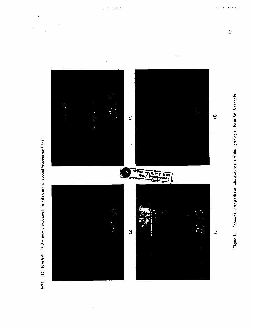
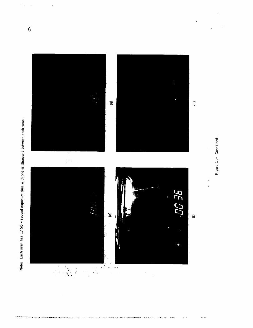
Four motion picture camerasrecorded lightning discharge channelsnear the launch tower. These photographs, together with video-tape rec-ords from the abort advisory television camera (figs. 1 and 2), show two
discharge channels. The duration of each scan in figure 1 is 1/60 second
with 1 millisecond between scans. These photographs were obtained from
video-tape records of the actual event. The bright lightning channel
apparently saturated the vidicon tube in scan b, and the tube remained
saturated for scans c and d. The image began decaying in scan e and re-
quired four scans for total decay. Scan f shows the second lightning
channel, which developed approximately 60 milliseconds after the first.
One of the channels, located about 1500 feet from the launch umbilical
tower, showed pronounced downward branching and appeared to last 50 milli-
seconds in the motion picture photographs. Another channel, partly ob-
scured by steam and clouds and about 100 feet from the launch umbilical
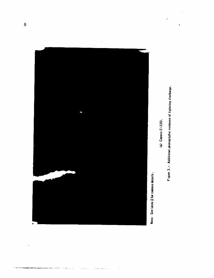
tower, also lasted about 50 milliseconds. One frame from each of the
motion picture cameras that recorded the lightning strike at 36.5 seconds
are shown in figure 3.
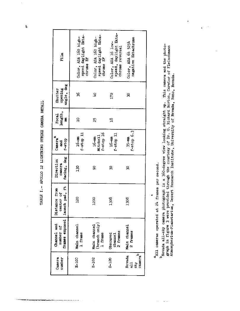
Table I shows the types of cameras used together with films, lens
openings, and shutter opening angles. All cameras were operated at a
speed of 24 frames per second. Figure 4 shows the camera sites and the
approximate locations of where the channels contacted the ground.
I-I
O3
0
I.-I
0,1
I
I-I
f_
f-I
I
o_
I
o_ o_,_ o_ o_
_D 0 0 0
0 _rx oOOJ ,-I
._o_ _
I _r-ll I I
0 0 0 0
0 0 cO0 0 0
C_ 0,1 .0 _1
o o _ _-_"
I0
_ m.1_ oM
,--I
O
m rD
4_
"_
o4._
O .,.-I
% O4._
O ! ._0 0_,._
% ,--t N
_J
_J.o
o
0
E
x
LI
I
,o
t--
-g
o
Z
e,Jv
e-0
e-
0
e-
.o.0
_J
_J
g
!
._
IJ.
6
c.)_n
..Cc.3
GJ
r-,
aJ
t-O
.I
E
c-o
°_
E.I
X
U
!
,,.-I
.,C
U
0o
0
¥ ",
oc.)
I
g,I
I.i_
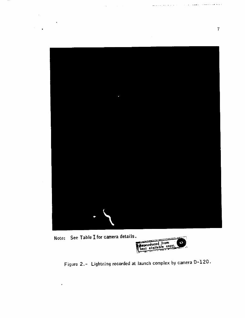
Note:
Figure 2.-
See Table I for camera details. ___..____.__----:
_a .trom " IP.J
Lightning recorded at launch complex by camera D-120.
8
0_
ucJ_
"0
0_
CT_
_J
0 aJ
W aJ
0
L-
_JqJ0
°_
i o
!
c_
cJ
I-I
qJ
0Z

c_0
Q_
mo_t_
I o
Q_c_
_JC_
0Z

i0
Note: See table 1' for camera details.
(c) Nevada all-sky camera.
Figure 3.- Concluded.

11.
North
l_Television
camera
E_IOZcamera
E-IO0
Lightning channel
Launchumbilical
tower
C__i/_ Nevada
camera
D-120
camera
Lightning
Craw lerway
Figure 4.- Camera locations and lightning channels on launch complex 39A.
12
ATMOSPHERIC ENVIRONMENT
On November 13, the d_y before the Apollo 12 launch, an intense low-
pressure trough in the upper atmosphere had evolved over the east central
United States from the Great Lakes down the Mississippi Valley into the
Gulf of Mexico. A surface cold front related to this upper air circula-
tion extended from the Atlantic, Just west of Bermuda, across northern
Florida and westward along the Gulf Coast. A broad band of cloudiness
and precipitation, punctuated by numerous thunderstorms, spanned the cen-
tral part of Florida from the east coast far out into the Gulf of Mexico
and lay over the launch area during the afternoon and evening. A weak
low-pressure wave, traveling eastward along the cold front, traversed the
northern part of Florida during the day and retarded the southward move-
ment of the front.
During the night of November 13, the band of inclement weather pushed
southward into Florida, however, thunderstorms had ended in the launch
area early in the evening. No precipitation or weather of consequence
identified the front, either by visual observation or by radar, and al-though clouds covered all of the state between the band of intense thun-
derstorms and the frontal area, only scattered light showers occurred dur-
ing the early morning hours of November lb. However, soon after daybreak,
a nearly solid line of precipitation echoes appeared on radar displays,
providing positive identification of the cold front activity.
At the time of launch (ii:22 a.m.e.s.t.), the cold front was passing
through the Kennedy Space Center. Radar echoes extended across Florida
from northeast of the Cape Kennedy area and averaged 20 miles in width,
although in places the band of echoes was 30 miles wide. Tops of the
cumulus congestus clouds reached a maximum of 23 000 feet within a range
of 30 miles, according to radar operators' reports. Winds aloft were
southwest or west-southwest from 3000 to 50 000 feet, and speed ranged
from 36 knots at 3000 feet to a maximum of 90 knots at h7 000 feet. The
general weather conditions in the vicinity of the launch complex were
highly variable with clouds reported between 800 and 1500 feet and the
overcast between about 2000 and l0 000 feet. There were light rainshowers
with southwest winds. Detail weather conditions in the area are shown in
table II. Less than an hour after launch, the precipitation had ended in
the launch complex area and the skies were clearing as the cold front
moved southeastwardly during the remainder of the day. The frontal loca-
tion h hours prior to launch is shown in figure 5.
After lift-off, the vehicle was observed until it was obscured by
the low cloud ceiling. An electrical discharge to the launch complex was
observed about 36.5 seconds after lift-off. At that time, and again at
52 seconds, sferics equipment indicated discharges as the space vehicle

13
O!
H
OHE_H
0rj
I
I-..-t
E_
r-t.el
r.3 _
_.o
O _
o_1
_'_mNl
,d m
_ O°_
%
M
I1)
G)M
i1)
rj
I
o%O
.f-t
O.f-I
4-_
4-_
r--t
O
,r..I
_O
ID
O
I
O
ffl
(2)
I1) ©
°_-t O
,CC o
o
o
O
00
OJ
F._
r_
o
oOx
_ ocO
I m '_D.._
m 0
"_ u-,
o
.O
0 0 _)
_o_o 0
OOO
_OOO
_ (2)
£e£ °OOO 0)
ogo_°_..I
I
I
°,-I
tl0.H
I
_g,-t._
cO
o o
M_ ',D
oOO
_ O
.._"0
-_,._0
ot'--
t'--
o
0
__)
°ri
*H O
OO
O
o
O_
cO
OO
°r"l
O0 _'_
CO OJOJ
O_-_
•_ OO
°,-.t _
"_ I
o _
O N _
.- _
_ g-_ 008
o 0
O 113
Ctl_l_-t ,.-4
0 0I I
_ 4_
..e.t,--t m _1
•rt f'¢3el _.D
I1)%
_,_
000
0_OJ
0
000
cO
I;M
°r..t
@4-_
O
@
o.
°,--t _
%a)"_
N._O_

14
was ascending through the clouds. No lightning had been observed prior
to lift-off nor was any lightning visually observed after the 36.5-second
incident. The lightning was recorded on film and is discussed in the
lightning photography section of this report. At 36.5 seconds, the ve-hicle was at about 6400 feet, and at 52 seconds the vehicle was at about14 400 feet.
Traces of the potential gradient measurements taken by eight radio-
active devices (fig. 6) during the final countdown period are shown in
figure 7. The instrumentation description is given in Appendix A. The
traces in figure 7 show a variability in frequency and magnitude of the
potential gradient at the point of measurement and are indicative of
rapidly and highly fluctuating electric fields above the launch complex
area. It should be noted that the devices are calibrated in the labora-
tory. No additional corrections, such as for wind or exposure, have been
applied to the data. The tabulated potential gradient readings were asfollows :
Site Indicated potential gradient Potential gradient range,
no. at lift-off (ll:00 to 11:22 a.m.e.s.t.)
I 0 +3 _ 0
2 +5 +6 _ -15
3 -3 -I _ -5
4 0 0_-3
5 +5 +5 _ -9
6 -1 0
7 0 o_-3
8 +i +6 _ -ll

15
C3J_D
_J
v
C_
C_
0
ID
_n
0
0
0°_
O
0_n
LL
!
Q__B
°_
LL

].6
S ire
Indian river
Site 5
Site 4
3
Site 7
i!iiiiiii!!i!ii!::AtlanticOcean
complex 39
I I
0 1
Mile
I
2
Site 2North _)•
Note:(_) Weather stations
Banana riverSite 1_
Figure 6.- Location sites for lightning instrumentation.

17
-15
15
-15
0"E_D
15
"E
C
0
15
Site 1
Site Z
Site 3
Site 5
7
Site 6
v'--'-
Site 7
-15
1510
Site 4
11 12
Site 8
10 11 12
Time, hr, e.s.t.
Note: These data showtrends ofthe potential gradient during launch day.
_ Time of launch; width of bandindicates time uncertainty of the trace.
Figure 7.- Potential gradient recordings during launch day.
18
EFFECTS ON SPACE VEHICLE
Spacecraft
There were many spacecraft indications of effects from the dischargeat 36.5 seconds. Also, at about 52 seconds, similar types of indications
were noted but to a lesser degree. Most of the effects were temporary
except for the permanent damage sustained by nine data measurements. None
of the conditions, including the loss of measurement parameters, had anyimpact on the overall operation of the mission.
The many temporary conditions included momentary interruption of
communications, disturbances on instrumentation measurements, illumina-
tion of many warning lights and alarms in the crew compartment, discon-
nection of the three fuel cells from the buses, loss of attitude reference
(tumbling) by the inertial platform, and disturbances to the timing system
and clocks. Some of the more significant spacecraft effects will be dis-
cussed to permit an understanding of the mechanism which enabled the elec-
trical discharge to affect the systems.
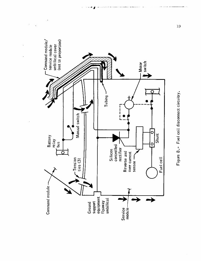
Fuel cells.- At about 36.5 seconds, the fuel cells were abruptly and
automatically disconnected from the spacecraft power buses, with the re-
sultant alarms normally associated with total fuel cell disconnection.
The basic elements that are typical for each of the three fuel cells asso-
ciated with the automatic fuel cell disconnection circuitry and switches
are shown in figure 8. Automatic disconnection of the fuel cells takes
place when sufficient current flows through the shunt. If the current
exceeds a certain value, the integrating circuit within the disconnect
circuitry will gate ON the silicon controlled rectifier. For example, if
300 amperes were applied through the shunt, the integrating circuit would
require between 1 and 3 seconds to reach the threshold of the circuit and
gate ON the silicon controlled rectifier. Once the rectifier is gated ON,
current will flow from the bus to the motor-driven switch, which requires
0.i second to disconnect the fuel cells from the bus. The likelihood of
a high current flow through the shunt causing the disconnect can be ruled
out for several reasons but primarily because the fuel cells simply cannot
supply the energy levels required by the integrating circuit to gate ONthe silicon controlled rectifier in a time frame of milliseconds.
A silicon controlled rectifier has the characteristic of being sen-
sitive to the rate of voltage change (dV/dt) on the anode (power side).
The rectifiers in the disconnect circuit will gate ON without a gating
signal if 500 V/microsecond is imposed on the anode or if the anode volt-
age exceeds 200 volts. The rate of voltage rise for a lightning dischargeis consistent with the 500 V/microsecond value. If the turn on mechanism
was due to exceeding 200 volts (breakover voltage) on the rectifier anode,
19
co
G__.-t.-0
u')._
LI..
I
CO
°_

2O
it is likely that the rectifier would have been damaged. However, the
rectifiers were not damaged as verified by the successful reconnection of
fuel cells to the buses. This characteristic provides the suspected mech-
anism (as dV/dt) for initiating the fuel cell disconnects. Figure 8 shows
two methods in which a high rate of potential change could have been im-
posed on the power line to the rectifier. The most likely method would
be induction as a result of the discharge transient through the conducting
path of the structure in the area of the umbilical cover. The other is a
direct input through a wire connected to an exterior umbilical.
There was no indication of any damage to the disconnect system or to
the fuel cells. The fuel cells were manually reconnected to the buses
and operated properly for the remainder of the mission.
As a result of the fuel cell disconnection, the main bus load of
75 amperes was being supplied only by entry batteries A and B, and the
main-bus voltage dropped momentarily to approximately 18 or 19 volts but
recovered to 23 or 24 volts within a few milliseconds. The low dc voltage
on the main buses resulted in the illumination of the undervoltage warning
lights, dropout of the signal conditioning equipment, and a lower voltage
input to the inverters. The momentary low voltage input to the inverters
tripped the ac undervoltage sensor and caused the ac bus 1 fail light toilluminate. The transient that affected the silicon controlled rectifiers
in the fuel cell disconnect circuitry also affected the silicon controlled
rectifiers in the ac overload circuits in the same manner. This further
substantiates the method by which the lightning affected the systems.
Instrumentation.- The nine sensors which failed consisted of five
thermocouples and four pressure/temperature transducers. These devices
are all located in the same general plane of the service module. Four of
the thermocouples which failed were mounted on the exterior skin of the
service module and were to be used to determine the relative sun angle ;
however, these are not required for mission success as alternate methods
of determining sun angle are available. The diodes and resistors in the
bridge circuits within these thermocouples can be overstressed by poten-
tials as low as 100 volts. The thermocouple locations expose the circuit
directly to the discharge, and the lack of shielding makes the system
highly susceptible to inductioa. The fifth failure was a thermal measure-
ment located on the nuclear particle analyzer, which is of the same de-
sign as the four thermocouples discussed previously.
The remaining four sensors which failed were used to measure propel-
lant quantities in the service module reaction control system. These sen-
sors detect pressure and temperature through a semiconductor strain gage
mounted on a pressure-sensing diaphragm on each of the four propellant
tanks. In addition to the diodes and resistors which can be affected by
potentials, the gage itself is very sensitive to current, particularly
21
because of the l-mil wire attached to the semiconductors. Alternate meansof determining propellant quantity were available; therefore, these fail-ures had no effect on the mission.
After the discharge at 36.5 seconds the computer data showedthatthe computer register containing the coupling display unit X-axis and
Y-axis readouts changed. The coupling display unit provides the computer
with the inertial measurement unit gimbal angles, in digital form. Since
the gimbal angles did not change, the most likely cause was the coupling
display unit circuitry, which is inherently sensitive to low-voltage tran-
sients between chassis and signal ground. These conditions have been ex-
perienced previously in ground tests. The computer data also indicated
that five computer restarts had taken place. These were most probably
caused by the voltage drop when the fuel cells disconnected from the bus.
Fail alarms noted in the fail register were caused by the coupling dis-
play unit activity.
Guidance system.- The 52-second discharge also affected the guidance
system. When data were recovered several seconds after the discharge, the
inertial measurement unit gimbals were driving at approximately 35 deg/see,
indicating the platform had tumbled. Also, a number of bits in the computer
channels had been set, and all were associated with gimbal lock, coarse
align, loss of attitude, etc.
The most likely cause of the tumbling condition was the setting of
high-order bits in the coupling display unit as a result of the voltage
transients introduced into the circuits. At 52 seconds, however, the
Z-axis coupling display unit (middle gimbal) was also affected such that
the readout exceeded 85 degrees. At 85 degrees the computer, sensing im-
pending gimbal lock, will automatically change the platform to the coarse
align mode. Under these conditions, the inertial measurement unit/coupling
display unit servo loop becomes unstable and continuously drives the gim-
b als.
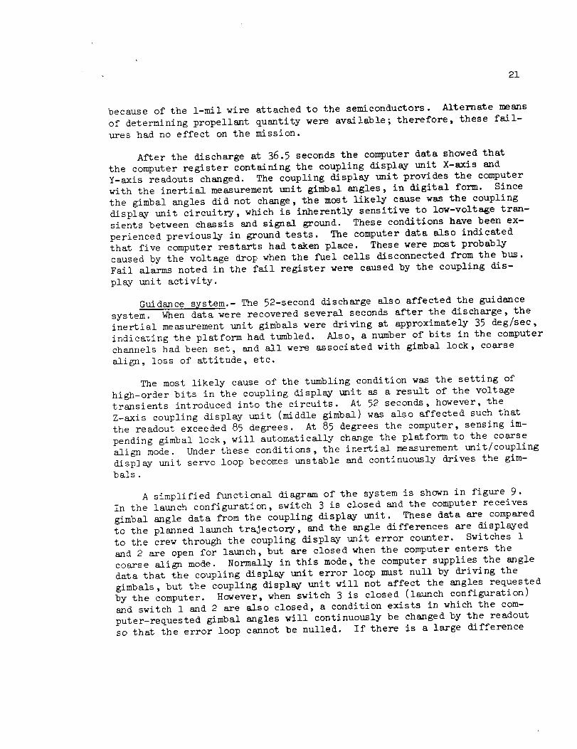
A simplified functional diagram of the system is shown in figure 9.
In the launch configuration, switch 3 is closed and the computer receives
gimbal angle data from the coupling display unit. These data are compared
to the planned launch trajectory, and the angle differences are displayed
to the crew through the coupling display unit error counter. Switches 1
and 2 are open for launch, but are closed when the computer enters the
coarse align mode. Normally in this mode, the computer supplies the angle
data that the coupling display unit error loop must null by driving the
gimbals, but the coupling display unit will not affect the angles requested
by the computer. However, when switch 3 is closed (launch configuration)
and switch 1 and 2 are also closed, a condition exists in which the com-
puter-requested gimbal angles will continuously be changed by the readout
so that the error loop cannot be nulled. If there is a large difference

22
Analoggimbal
angles
! Inertial 1"-_
Imeasurement.L-- ___
I J
torquing /signal
Digitalgimbal
angles --_
Coupling display ] _
unit readout |
counter
Coupling display _
unit error I_
counter I =
To attitude
error display
3
A --
v v
Desired
ang le
--Gimbal
alignmentangle
Figure 9.- Simplified functional diagram of the computer/inertial measurement unit interface.

23
between the coupling display unit and platform angle when entering coarse
align, regardless of the computer output, the platform will become un-stable. This condition has been demonstrated in a bench test of the sys-
tem simulating the observed conditions.
The lunar module instrumentation system does not operate during
launch, consequently any transient effects on that vehicle would be un-
known. Permanent effects may be detectable when the instrumentation sys-
tem is activated later in the flight. However, because of the lunar
module location inside the adapter, no effects would have been expected.
In any event, the checkout of the lunar module enroute to the moon, as
well as the normal operation of all systems during the mission indicated
no systems had been affected.
Launch Vehicle
From initial quick-look data, the only effects on the launch vehicle
were minor disturbances on three continuous channel piezoelectric vibra-
tion measurements at about 36.5 seconds. A detailed investigation of the
data, conducted until 21 days after launch, showed 109 of 1477 measure-
ments indicating transient disturbances during the 36.5-second discharge
period. No measurements were lost in the launch vehicle as a result of
the lightning strike.
Launch vehicle data system indications.- Launch vehicle telemetered
data were examined in detail in the 36.5-second and 52-second time periods
to determine the effects that could be attributed to lightning or a static
discharge. Forty-five measurements in the instrument unit experienced a
disturbance in the 36.5-second time period. S-IVB data systems experienced
disturbances at this time on all 15 single sideband telemetry channels and
on 45 pulse code modulated data samples. Three piezoelectric vibration
measurements on the S-II stage were also affected at this time with one
disturbance noted on the S-IC. At 52 seconds, a disturbance was noted
on one S-II piezoelectric vibration measurement. All of the disturbances
noted were transients of variable amplitudes. No pattern was apparent
either in geometrical location or in the magnitude of the disturbance
other than most measurements affected were located on the upper two stages
of the vehicle. There was no damage or subsequent data degradation noted.
The nature and randomness of the transients are characteristic of effects
caused by a massive external electrical disturbance.
The telemetered Q-ball output appeared normal throughout the entire
active period of flight; however, the telemetered measurements of the
Q-ball did not agree with launch wind profile information. A simple
laboratory test is being considered to determine whether a high electric
field could contribute to an error in the output from the Q-ball trans-
duce rs.

24
Launch vehicle data adapter/digital computer indications.- Two devi-
ations were observed by the launch vehicle digital computer during the
initial boost phase of flight at approximately 36 seconds. The Z (down-
range) accelerometer A and B counters disagreed and the Y (pitch) gimbalreading failed a reasonableness test at this time.
At 36.6 seconds, the pitch gimbal crossover detection counter read-
ing changed 2.8 degrees over one minor loop computation cycle time
(40 milliseconds). This value exceeded the reasonableness test value of
0.h degree and was properly rejected by the computer. The computer uti-
lized the previous gimbal angle reading, and returned to normal gimbal
angle processing. Subsequent readings were reasonable.
At 37.01 seconds, the A and B counters of the Z (downrange) acceler-
ometer differed by nine counts (0.45 meters per second). Both counters
were reasonable, but the B counter was closer to the established force to
mass ratio profile. The launch vehicle digital computer flight program
accelerometer error processing properly selected the B reading.
The computer operated normally by going into the alternate mode of
operation when the deviations were noted in the signals from the platform.
The redundant signals were within the required tolerances and the computer
transferred back into its normal mode of operation with no change in the
operation of the flight program. The guidance errors which were observed
Just prior to the vehicle orbiting the earth do not appear to be corre-
lated _-ith the pitch gimbal reasonableness test failure or the downrange
accelerometer counter disagreement which occurred at the time of the light-ning phenomena.
These deviations have been closely correlated with an electrical im-
pulse that passed from the top of the vehicle through all stages, 36.5 sec-onds after lift-off.
Launch Complex
A complete investigation showed no ground support equipment abnor-
malities which could be attributed to the lightning discharge.

............ L
25
CAUSE OF DISCHARGES
There is general agreement in the scientific community involved with
atmospheric electricity that the Apollo 12 lightning discharges at 36.5
and 52 seconds were triggered by the presence of the Apollo 12 vehicle.
One other suggestion which has been discounted, is worthy of discussion
and that is, as the vehicle ascended, it generated sufficient static elec-
tricity to produce a discharge.
The discussion that follows has been extracted from analyses per-
formed by several authorities in atmospheric electricity. A specific de-
tailed analysis is contained in Appendix B.
Electrostatic Discharge Theory
An estimate of the amount of energy expended in the discharge channels
observed at 36.5 seconds can be compared with that which might be produced
by static electrification of the space vehicle. Photographs show that the
channels to the ground at 36.5 seconds have the appearance of normal light-
ning. The intensity of light from the channels is comparable to that of
natural lightning. A lightning detector 8 miles from the launch complex
and an electric field detector Ii miles from the complex both recorded sig-
nals similar to those of natural lightning. The assumption can then be
made that the energy of the discharge must have been characteristic of nat-
ural lightning, which is in the range 105 to 106 joules per meter of chan-
nel length and corresponds to a total energy of at least 108 joules. If
this energy was supplied by static electrical charge accumulated on the ve-
hicle, the energy would be 0.5 Q2/C, where C is the capacitance and Q is
the charge on the vehicle. At 6400 feet, the capacitance of the vehicle
depends on the electrical length and diameter assumed for the exhaust plume.
The length of the vehicle is 364 feet. If it is assumed that the electri-
cally conducting exhaust plume broadens to 50 feet and is up to 5 times the
length of the vehicle, the vehicle will behave electrically like an ellip-
soid with a 50-foot minor axis and a 1900-foot major axis. The capaci-
tance of this object for this exhaust plume length is about 104 picofarads.
Corona discharge limits the field strength at the vehicle surface
to about 2 x 10⁶ V/m. Then, the maximum charge which can accumulate on
the vehicle is about 10 -2 coulombs. The corresponding electrostatic en-
ergy is no more than 104 joules, which is 4 orders of magnitude less than
the energy observed. For this reason, static electrification cannot be
considered the source of the discharge at 36.5 seconds.
26
Vehicle-Triggered Lightning Theory
In order for the vehicle to trigger a lightning discharge, electrified
clouds are required. Just prior to the launch of Apollo 12, the available
instruments did not show any lightning activity in the area; however, the
electric field meters showed the existence of electric charges in the
clouds overhead (fig. 7). These clouds extended from about 1000 feet to
above 20 000 feet, and rain was falling from them. The zero-degree iso-
therm was at an altitude of about 12 400 feet, so that ice was forming
in the clouds. Rain and ice formation are nearly always associated with
strong electrification of clouds. Thus, while the space vehicle was not
launched into an active thunderstorm, it was launched into clouds which
contained significant amounts of electric charge. The electric field
meters showed (fig. 7) an oscillatory pattern, indicating that electric
charges in the clouds were distributed in a complex way.
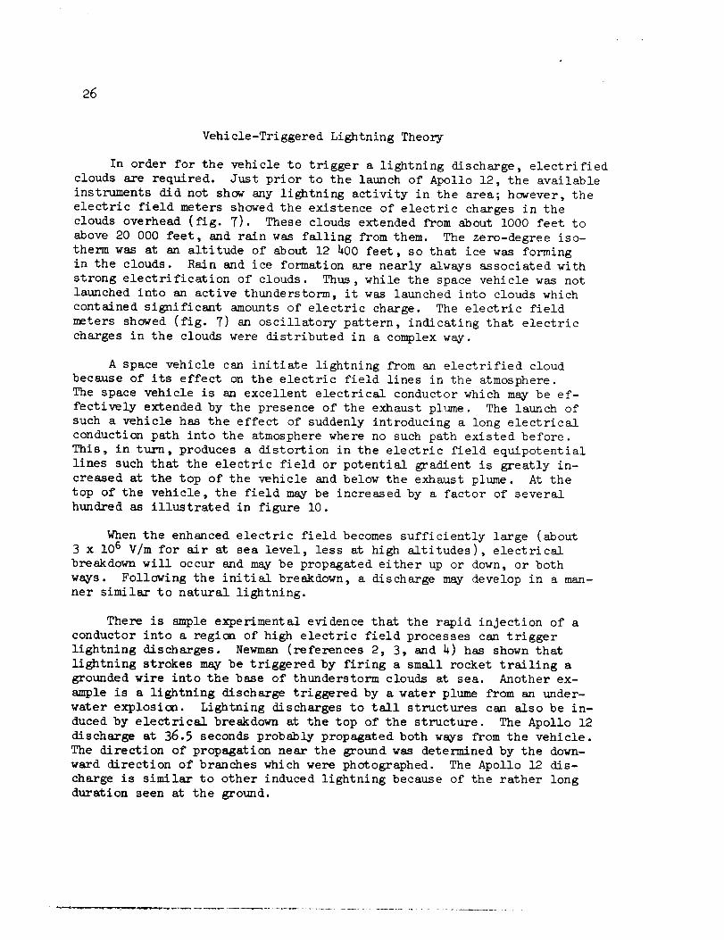
A space vehicle can initiate lightning from an electrified cloud
because of its effect on the electric field lines in the atmosphere.
The space vehicle is an excellent electrical conductor which may be ef-
fectively extended by the presence of the exhaust plume. The launch of
such a vehicle has the effect of suddenly introducing a long electrical
conduction path into the atmosphere where no such path existed before.
This, in turn, produces a distortion in the electric field equipotential
lines such that the electric field or potential gradient is greatly in-
creased at the top of the vehicle and below the exhaust plume. At the
top of the vehicle, the field may be increased by a factor of several
hundred as illustrated in figure i0.
When the enhanced electric field becomes sufficiently large (about
3 x lO 6 V/m for air at sea level, less at high altitudes), electrical
breakdown will occur and may be propagated either up or down, or both
ways. Following the initial breakdown, a discharge may develop in a man-
ner similar to natural lightning.
There is ample experimental evidence that the rapid injection of a
conductor into a region of high electric field processes can trigger
lightning discharges. Newman (references 2, 3, and 4) has shown that
lightning strokes m_y be triggered by firing a small rocket trailing a
grounded wire into the base of thunderstorm clouds at sea. Another ex-
ample is a lightning discharge triggered by a water plume from an under-
water explosion. Lightning discharges to tall structures can also be in-
duced by electrical breakdown at the top of the structure. The Apollo 12
discharge at 36.5 seconds probably propagated both ws_vs from the vehicle.
The direction of propagation near the ground was determined by the down-
ward direction of branches which were photographed. The Apollo 12 dis-
charge is similar to other induced lightning because of the rather long
duration seen at the ground.

27
f f t"- _,_lncreased field
/ / \ \ --..\ \\ \\ \
\\
\\
\\
,' //
/ // /f
I /I
II
11F
Electric field
equipotential lines-_
\ /
\ /\ \ I I
\ \ / /\ \ / I
--._ \ \ I I _---
_\ \ \ I I I f
\\ \\ \\ iii I i I
_" _""_ _ _lncreased field
Figure 10.- Enhancement of electric fields at each end of the space vehicle.

28
An indication of what might have been the discharge current at thevehicle is shown in figure ll. This estimate is based on the nature of
the lightning recorded on film and on currents measured during othertriggered discharges and natural lightning.
16 x 103
12 -
8
4
_..,,__A , I I i- - I '
0 _20 40 60 80 100 120
_. 1_ Time, millisecondsi' 16 X 103 ......
r
12
8
4
I I I I I
0 20 40 60 80 100 120
Time, microseconds
Figure 11.-" Probable current chara.cteristics of the dischargea_/56.5 seconds seen at the space vehicle.

29
FLORIDA METEOROLOGICAL CONDITIONS ASSOCIATED
WITH ELECTRIFIED CLOUDS
Because of the high frequency of thunderstorm occurrence in the
Cape Kennedy area, a comprehensive review has been performed of typical
conditions associated with potentially dangerous electric fields. This
basic information was required prior to definition and evaluation of
realistic launch rules. The frequency of thunderstorm conditions in the
Eastern Test Range area is shown in figure 12 (see reference 5.)
Jan
Mar
May
_Jul
Sept
Nov
Jan
Note: All values shown are in percent.
I I I I ! I I I I I I I
O1 03 05 07 09 11 13 15 17 19 21 23
Hour, e.s.t.
Figure 12.- Probability of thunderstorm occurrence by months plotted
against time of day in the Cape Kennedy area.
Any thunderstorm, regardless of the associated atmospheric condi-
tions, creates natural lightning situations. Even when thunderstorms
(either fully developed or decaying) are located outside the launch com-
plex area, the associated cloud anvil may create a hazard. On occasion,
lightning from such anvils has been observed traveling to ground outside
the cloud.

30
There are three other cloud conditions that may produce high elec-
tric fields. The first system of concern relates to the movement of cold
fronts, or squall lines, without thunderstorms but producing rain or rain
showers and extending vertically above i0 000 feet. As indicated by the
Apollo 12 incident, such conditions can cause high potential gradients of
such a magnitude that cloud discharges may take place when a man-made dis-
charge path is introduced (reference 6). Such situations develop even when
natural lightning phenomena would not normally occur nor be 'anticipated.
While fronts through the Cape Kennedy area are often not active with re-
spect to thunderstorms, during the period of November through March, about
4 to 6 fronts per month can be expected (about 80 percent cold fronts. )
Deep middle cloud layers, 6000 feet or more in thickness and with
or without rain falling to the ground, is the second condition of concern.
Such clouds would normally be based at least 8000 feet above ground. They
are usually associated with large-scale cyclonic circulations and may ex-
tend outward several hundred miles from the circulation center. These
conditions may or may not produce thunderstorms. Although the potential
gradients may be quite high, natural lightning rarely occurs. However,
cloud discharge may take place when a man-created discharge path is intro-duced.
The third system is quite common to the Cape Kennedy area and is
associated with showers falling from cumulus clouds moving in from the
ocean. Such clouds may have vertical developments of l0 000 to 25 000
feet with high electric fields.
In summary, several meteorological situations common to the Cape
Kennedy area can create electrical hazards even though natural lightningmay not exist.
Effects of Atmospheric Conditions on Launch Window
Certain meteorological phenomena are indicative of environmental
conditions related to increased atmospheric electrical activity. To eval-
uate the occurrence of these conditions at Cape Kennedy, the past weather
records were analyzed and the frequencies of occurrence of specific phe-
nomena were determined. The results of this analysis are applied here to
obtain an insight to the probability at each hour of conditions which are
indicative of increased electrical activity in the atmosphere.
The analysis also includes determinations of conditions at hours
subsequent to each unfavorable hour to determine the improved chancesgained with the passage of time in a launch window.

31
Criteria
The criteria selected for this analysis which might be consideredin establishing an unfavorable launch situation at CapeKennedyare:
LI = wind >--28knots at 60-foot reference level
L2 = thunderstorm with both a ceiling and precipitation
The criteria which also might be considered indicative of increasedatmospheric electrical activity are:
LB = precipitation without a thunderstorm
L4 = cumuliform type cloud ceiling_<4000 feet except any ceiling_<4000feet is unfavorable if precipitation is reported.
Designation of the criteria as L is arbitrary. (See figure 13.)
A wind of>-28 knots is designated for Ll since it is approximatelythe samelimitation used for previous Apollo launches.
Criterion L2 is specified as shownbased on the consideration thata thunderstorm not close enough to produce a ceiling or precipitation atthe station is not indicative of a launch through a cumulonimbusclouds.
Criterion LB is established based on the premise that any precipita-tion must be considered indicative of increased electrical activity. Thecriterion excludes thunderstorm precipitation since this is included incriterion L2.
The basis for criterion L4 is that the occurrence of cumuliform(vertical motion) type clouds in sufficient quantity to produce a ceilingat the reporting point is indicative of increased electrical activitywhether or not precipitation is occurring. A previous analysis, notincluded here, showedthat the base of cumuliform clouds at CapeKennedywas almost never above 4000 feet, hence 4000 feet was selected as theceiling limitation. Criterion L4 includes cases of ceiling 4000 feetwith precipitation when cumuliform clouds are not reported since, asnoted above, any reported precipitation is considered indicative of in-creased atmospheric electrical activity.
The intent of this analysis is to illustrate the degree of degrada-tion in launch probability with the addition of further atmospheric con-straints. The constraint of no flight through a thunderstorm when addedto the current Apollo launch ground wind constraint does not significantlyinfluence the fall, winter, and spring launch probabilities. The primaryinfluence of thunderstorms on launches occurs during the summermonths.
32
However, a constraint for no launch during rain (which is a strong indi-cator of high potential gradients in the clouds) adds two to four percentto the delay probability. This maynot be critical depending upon launchwindow. Whenconsideration is given to the launch window, the launchdelay probabilities are reduced as the length of the launch window in-creases; for example, the delay probability becomesabout one-half thatshownin figure 13 for a 3-hour launch window.

}3
(%1
\
IIII
,q. I/
_J
I
\
I I\ ",a I
\\ I
\ I'"\ /1 iI LI
I \ _ -
v I _ vI I _| /
/
I i/ If
0
Z
o
," \I I //-__\\
_.-" \ i ._ ._ ._ _ \ \ I
" / /_J/\' '-\_/
x ,'-,,\
Io
('M _1" ,q. l_1 "-J
I I I I ICO _ .,,0 0 '_"
('l"S'a) ,Iq'aw!I
.E0
"_ _ co . .o_
"0
e- e_
_ e
_j _
u.

34.
(':l'S'a) JLI 'am!J.
Z
0
v_ "_-
o 00 -o E __
-_ ._ _ __E
.Q
' _a
2

3_
IQ
CO GO
I I IGO C_I
('l's'a) J4 'atu!j.
I,,0
O0 O0
I0
Od
O0
I
Z
0
_ 0Jt/5
_ i_ _ .__"_ _ _ _ ._-_ _. -_
_ o
_ _._. _ _._' _'_-_ o o .
-.1
e-
E
I'-
LL
e-
36
I I I I
u
m oZ
c-
.w
__ '_ _ ° .-
e,.
,<
e,.
E
LI.
_1
e-

37
VEHICLE DESIGN CONSIDERATIONS
There are two basic effects of lightning on the launch vehicle and
spacecraft systems. The first is the induction of electric current into
the circuitry and is produced by the flow of current through the basic
vehicle structure with the induced potential proportional to the rate of
change of current. This condition may cause an inadvertent function or
even permanent damage. This leads to the second basic effect of light-
ning: the damage that may result from the energy dissipation along the
current flow path (I2R). The damage along the conducting path can vary
from discoloration to explosive destruction of the material depending
on the current level and duration in relation to the physical dimensions
of the material. This damage may result whether the current is induced
or introduced directly into the system by the discharge.
The launch vehicle was designed for operation in hazardous electric
fields. The spacecraft design, on the other hand, incorporated good de-
sign practices to guard against electrical discharges; however, the spec-
ific design did not in all areas, consider operations in hazardous elec-
tric fields. The question is, how immune is the present design of the
spacecraft systems to the effects of electrical discharges of the type
experienced on Apollo 12? Moreover, are there any systems or componentswhich could be affected such that an unsafe condition would be created?
To this end, the systems of the spacecraft and launch vehicle were reas-
sessed for operation under the influence of triggered electrical discharges
associated with clouds.
The Crew Safety Panel reassessed the ordnance system and the automatic
abort system of the vehicles. The findings of the panel are reflected in
the discussions which follow.
Spacecraft
Structural bonding.- The current associated with an electrical dis-
charge of a cloud will seek the easiest path to discharge the potential.
For an Apollo launch vehicle directly involved with the discharge, the
path of current flow would be on the vehicle outer metallic skin, which
provides a continuous low resistance conductive path from bow to stern.
Bonding between basic structure and structural ties to metal components
insures a continuous low resistance path. The bonding is measured and
verified to meet requirements of 0.01 ohm between major assemblies of the
spacecraft systems. Two flyaway umbilicals do not have covers. The main
bus power during ground checkout for both the lunar module and commandand service modules are provided through these umbilicals and this cir-
cuitry has an interrupt function. However, all of the other functions onthese umbilicals are not protected and therefore, do provide a possible
path for induced voltages.

38
Emergency detection system.- The emergency detection system has been
assessed previously from the safety standpoint. A discharge in flight
would not be expected to have a direct effect on the system such that an
automatically initiated abort would inadvertently occur or such that a
required automatic abort would be prevented from taking place. Calcula-
tions given in Appendix C are based on conservative assumptions and indi-
cate that induction into the system would probably not cause any change.
A secondary effect that was also considered occurred on Apollo 12 when
the inadvertent disconnection of the fuel cells caused the battery bus
to momentarily drop (see fig. 14). Note that the voltage level did not
drop below the required level for the time delay relays in the system.
The operational configuration of the battery system supporting the emer-"
gency detection system on Apollo 12 is considered to be safe for futureflights.
Ordnance circuits.- The circuit designs employ safety features for
protection against induced voltages, inadvertent operation, and static
discharges. These ordnance systems are considered safe from initiation
and reasonably secure from dudding as a result of electrical discharges.
All spacecraft ordnance functions are initiated by a single stand-
ardized initiator of the hot-wire type --Single Bridge Wire Apollo Stand-
ard Initiator. The pyrotechnic charge in this device is initiated by pas-
sing a current through the bridge wire; the resulting heat ignites the
charge which is in intimate contact with the wire. The resultant heat
and pressure output of the initiator in turn ignites the booster charge
in the cartridge to perform the desired function. Firing current _s sup-
plied by special batteries used only for ordnance systems. Figure 15 shows
a simplified schematic of the initiator and firing circuit; shielding is
not shown. Two switch closures in series are necessary to fire the initi-ator.
There are three ways that induction from lightning may cause aninitiator to fire:
a. Induced voltage across wires A and B
b. Induced voltage from wire A or B to the initiator case
c. Induced voltage to pull in the firing relays.
In the first item, wires A and B are shorted by the normally closed
contacts on the firing relay. If both wires are subjected to the same
induced voltage, however large (ignoring any shielding), no current will
flow through the bridge wire. In considering a differential induction
on wire A and B, the canard deploy circuit was analyzed because of its
close proximity to the skin over a long distance and the current density

39
0
rm
36
27
/t
- Battery bus voltage ,_j-_
A _ '_attery voltages based ___w
on ground test data
18
• . • ° .
I0 0 8 16 24 32___ 0
l Time, milliseconds
Ligntning strikeat 36.5 seconds
Figure 14.- Battery bus voltage and emergency detection systemrelay and timer voltage limits.

4o
0
._ Xo tJ.J
' N--.-......:'X'%"
ooool
e,,-o
0.--_
¢j
e-e-
0
toeoe4eooo4pooeeeoooeoJooeoeooeoe
_:_:{ooeoo_ooeee
ooooo
m
b
B i
.m
"ooD
Jl,
J!u
0
q
0
O
O
o
-4J
c-.
O
o
E
ut;3
"O_J
0_
,w
E
I
u_r-_
C3_
LL
41
is probably greatest on the tower due to the relatively small cross sec-
tional area. The details of the analysis are given in Appendix C. The
very conservative assumptions show a pulse energy of about 25 watts for
l0 microseconds. Based on the steady-state ignition characteristics, the
initiators should not fire. The initiators were tested to 1225 watts with-
out firing.
The second item requires a potential between the initiator case and
wire A or B. Again taking very conservative assumptions, a potential of
420 volts could exist from wire to case. Note in Figure 15 a spark gap
is provided and is the lowest resistance path in the circuit. A potential
of 1200 volts is necessary to cause a spark Jump at this point. Each ini-
tiator is subjected to 25 000 volts to insure that the spark Jump does not
cause ignition.
The possibility listed in the third item can be ruled out as very un-
likely since power for milliseconds is required to pull in these relays;
induction from lightning can last for microseconds.
Solid-state components.- From two standpoints, the most susceptible
areas in electrical circuits to lightning-type discharges are solid-state
devices. First, the lightning-induced effects which occur for time dura-
tions of microseconds are well within the response time of these compo-
nents; consequently, induction might initiate functions. Secondly, per-
manent damage might also result if the induced voltage exceeds a relati-
vely low value. Examples of these conditions happened on Apollo 12.
Initiation of functions through solid-state devices was believed to be the
basic cause of the fuel cell disconnect, most caution and warning alarms,
and the tumbling of the platform. Damage to solid-state devices in the
measurements which failed are believed to be the effects of induced volt-
age in the circuit.
The experience with ground testing on the spacecraft has shown that
induced effects into certain solid-state circuits, such as those associ-
ated with the caution and warning alarms, the coupling display unit read-
outs, pulse code modulation, etc., have occurred in the electromagnetic
environment associated with normal activation and operation of systems.
It is not surprising to experience similar situations with the electro-
magnetic environment associated with lightning. At this time, no practical
changes can be made to the spacecraft to further protect these components.
Spacecraft guidance computer.- There is no practical procedure to
eliminate the mechanism which led to the platform tumbling. However, be-
cause there is no requirement to align during launch, and the coarse-align
mode inhibits the manual takeover of the S-IVB guidance, a software change
is planned for Apollo 13 to prevent activation of the coarse-align mode
during launch. A gimbal-lock indication, either real or caused by coupling

42
display unit transients, will still be displayed to the crew but will beignored when the spacecraft digital autopilot is in the launch-vehicleconfiguration. Further software changes to provide protection againsttransients are being considered for Apollo 14.
LaunchVehicle
Even though there were no definite lightning protection requirementsin the design specification of the vehicle, high voltage discharge protec-tion was considered throughout the vehicle design. For example, a lowresistance bonding requirement according to specification MIL-B-5087Bbetween stages, covers on umbilicals after umbilical disconnect, not al-lowing the use of non-conductive surfaces in the vehicle, and suitablegrounding on the vehicle protuberances such as cable tunnels were usedin the design and construction of the vehicle.
Bonding.- The electrical bonding between stages causes the outer skinof the vehicle to act as the carrier of the discharge from the lightningphenomena. This aids in the protection of the internal equipment andelectrical networks. Total compliance to MIL-B-5087B or better impliesthe ability to withstand skin currents up to 200 000 ampereswithout phys-ical damage,but rigorous" determination of the upper limit by tests oranalyses is not practicable. The lack of direct data would cause the ve-hicle integrity (particularly with respect to digital systems) to bequestionable to a sufficient degree to warrant a complete systems test inthe event of any visible lightning strike whenthe vehicle is on the pad.The vehicle incorporates a two-wire direct current electrical system de-sign which reduces the possibility of an induced transient voltage in theelectrical networks. With the aid of these two design features, no elec-trical equipment was critically damagedin the launch vehicle.
Abort system.- The original concept utilized in the design of auto
abort system was to prevent an erroneous abort. The system has no single
point failures within the emergency detection system which would cause an
inadvertent abort nor prevent an abort when an actual emergency arises.
This is insured by the use of triple redundant circuitry, two out of three
voting in auto-abort sensing circuits and automatic abort initiation cir-
cuits.
All the auto abort system located in the launch vehicle is shielded
by the vehicle skin. This acts as a large metal can which provides a path
for the discharge from the lightning phenomena. The relay circuitry is
located in the emergency detection system distributor which is a metal
box, within the large metal can, that is grounded to the vehicle struc-
ture. The relay coils are mounted in metal cans which are structurally
grounded to the emergency detection system distributor. This system util-
izes relay logic having 30-millisecond timers that provide a delay in the
spacecraft to prevent any transient voltage from activating the auto abort
system.
_3
This system has three hot wires routed through separate cables fromthe instrument unit to the spacecraft to maintain six relays in the en-ergized position until either the auto abort bus is energized or space-craft separation occurs.
Ordnance.- The exploding bridge wire ordnance is designed specifi-
cally to prevent any response to random fields and electrostatic dis-
charges. Operation of the exploding bridge wire ignitors requires a unique
set of high energy parameters with a special "trigger" to assure predict-
able operation. The energy is derived from a capacitor which is normally
uncharged and requires 1.5 seconds to achieve operating levels. Lightning
discharges normally persist through time periods one to two orders of mag-
nitude less than one second. Compliance with MIL-I-6181D and MIL-B-5087B
(ASG) causes the units to be shielded through 360 spherical degrees and
prevents the system from being ground driven in addition to the protection
afforded by the vehicle structure.
All of the ordnance in this portion of the vehicle utilizes the ex-
ploding bridge wire method of ignition except the ordnance to start the
F-I engines. The F-I engine start ordnance uses a hot wire ignition;
however, it utilizes the same protective circuits to prevent erroneous
ignition as does the exploding bridge wire. The requirements to ignite
the exploding bridge wire detonators are 600 to 1200 volts dc with approx-
imately i000 amperes at a fast rise time of 0.i microsecond. Two input
signals are required for the exploding bridge wire firing unit to produce
the ignition conditions for the exploding bridge wire detonators. The
first signal applies power to the charging circuitry which charges a
capacitor to 2300 volts dc. Charging time is 1.5 seconds. The second
signal triggers an electronic switch causing the storage capacitor to
discharge through a discharge tube in series with the detonator wire
creating a high current to explode the wire. The charged capacitor will
bleed off the charge to a safe 300 volts within 15 seconds if the input
power is removed. If the trigger signal is received before the capacitor
is fully charged, the charging circuit is cut off, thereby preventing det-
onation from the firing unit. The detonator does not contain heat-
sensitive explosives and is not sensitive to static discharges, RF energy,
or inadvertent application of ground or vehicle power.
If a stray current from lightning did get into the networks that
command the exploding bridge wire firing unit, it is believed the solid
state components would no doubt be destroyed before the capacitor could
charge up, preventing a firing of the detonators. The cable from ex-
ploding bridge wire firing unit to the detonator is a maximum of forty-
eight inches in length, and is covered with six to eight interwoven wire
shieldings to eliminate any induced voltage to the detonators.
Launch vehicle design capability summary.- The probability of light-
ning damage to the vehicle hardware is deemed negligible. The computer
44
influence due to a lightning strike may be subtle and varied in flight.
The built-in programming checks and computer system redundancies are such
that no degrading first order effects due to lightning are known. The
auto abort system has been designed to provide an adequate safety margin
and no changes are considered necessary.
The probability of initiating launch vehicle ordnance by means of a
lightning strike is virtually nonexistent while the probability of dud-
ing is deemed negligible.
Launch Complex
This section assesses the physical structures and associated equip-
ment which make up the launch complex and determines the safety of the
complex while a vehicle is undergoing checkout prior to lift-off.
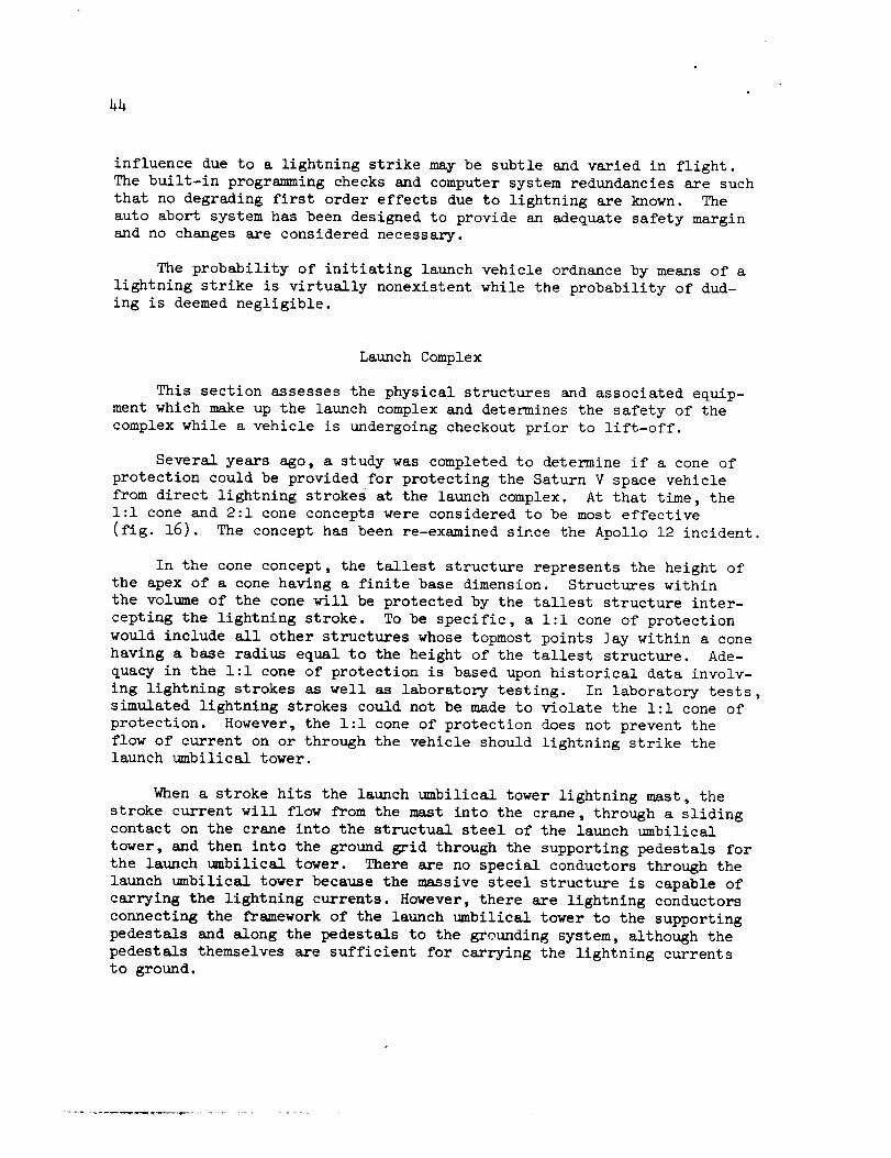
Several years ago, a study was completed to determine if a cone of
protection could be provided for protecting the Saturn V space vehicle
from direct lightning strokes at the launch complex. At that time, the
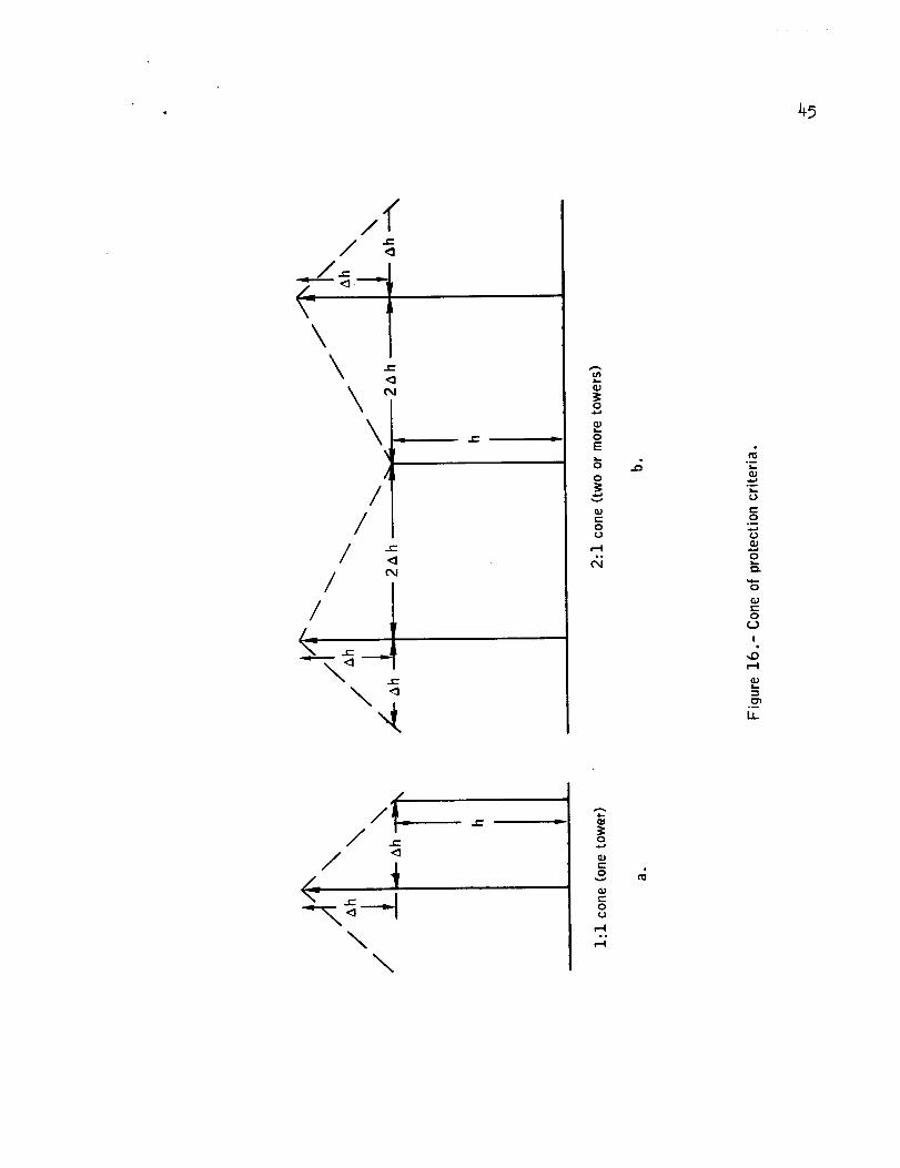
i:i cone and 2:1 cone concepts were considered to be most effective
(fig. 16). The concept has been re-examined since the Apollo 12 incident.
In the cone concept, the tallest structure represents the height ofthe apex of a cone having a finite base dimension. Structures within
the volume of the cone will be protected by the tallest structure inter-
cepting the lightning stroke. To be specific, a l:l cone of protection
would include all other structures whose topmost points ]ay within a cone
having a base radius equal to the height of the tallest structure. Ade-
quacy in the l:l cone of protection is based upon historical data involv-
ing lightning strokes as well as laboratory testing. In laboratory tests,
simulated lightning strokes could not be made to violate the l:l cone of
protection. However, the l:l cone of protection does not prevent the
flow of current on or through the vehicle should lightning strike thelaunch umbilical tower.
When a stroke hits the launch umbilical tower lightning mast, the
stroke current will flow from the mast into the crane, through a slidingcontact on the crane into the structual steel of the launch umbilical
tower, and then into the ground grid through the supporting pedestals for
the launch umbilical tower. There are no special conductors through the
launch umbilical tower because the massive steel structure is capable of
carrying the lightning currents. However, there are lightning conductors
connecting the framework of the launch umbilical tower to the supporting
pedestals and along the pedestals to the grounding system, although the
pedestals themselves are sufficient for carrying the lightning currents
to ground.
_5
/_
//
('%1/
/_
0
E
0
v
t-Oc.)
c-O
0
c-
O
I
\\
e-,
t-,,
o
0U

46 •
When the launch umbilical tower and vehicle are in transit to the
complex, there is a path to ground from the launch umbilical tower through
the crawler which drags a chain on the ground over a buried counterpoise.
In addition to passing through the legs of the tower, currents would
be flowing in metallic materials that extend up and down the launch umbil-
ical tower and also in the loop created by the launch umbilical tower/swing
arms/vehicle. These currents would be mainly due to magnetic coupling
from the main stroke path. To minimize the effects of induced currents
on electrical equipment on the launch umbilical tower and in the vehicle,
cables running up and down the tower have overall shields and are enclo-
sed in metal trays with covers and the trays are bonded to structure.
External cables on the various launch umbilical tower levels are
provided with overall shields which are grounded to the launch umbilical
tower structure. Also the cables that extend across the swing arms to
the vehicle have overall shields. To minimize personnel and equipment
hazard created by potential differences (caused by high-resistance pathsand different levels of magnetic flux), metallic structures have been
bonded together and grounded to the structure.
In recognition of the various current paths available, a re-evaluation
was performed relative to the present ground network. The results of this
evaluation indicates that some minor changes are desirable.
The analysis of electrical cabling in critical launch support systems
revealed that shielding to the control cables was not grounded. This will
be corrected by providing a grounding to cable shields. The affected
systems include the egress elevator, fly-away swing arms, damper arms, etc.
In addition, a study is being made on the possibility of grounding
arms 3, 9 and the damper arm. There is no "classical" grounding between
these arms and the launch umbilical tower, and there is no contact between
the arms and the skin of the vehicle. It is likely that the results of
this analysis will be the installation of grounding straps from the armsto the launch umbilical tower.
Historical data of lightning strokes on the launch umbilical tower
indicate that only two strokes have ever occurred. On May 27, 1966, atapproximately 1550 hours, a lightning stroke terminated on launch umbili-
cal tower 1 at pad A at launch complex 39. Vehicle 500F was on the pad
at the time. Analysis of magnetic link instrumentation indicated a peak
current of 50 000 amperes. Damage was limited to the anemometer which
was mounted on the same mast as the lightning terminal. During the pe-
riod from May 28 to June 21, 1966, a smaller stroke occurred. Apeak cur-rent of 6000 amperes was experienced. No damage was detected.

47
Re-examination of the space vehicle systems with Marshall Space Flight
Center and Manned Spacecraft Center verifies that if a strike should occur
to the launch umbilical tower, no significant hazard to the crew would be
initiated by the space vehicle or its associated ground support equipment.
Therefore, upon completion of ingress, the crew should remain on board,
should lightning conditions develop. However, the mission rule essenti-
ally states that the Launch Director will give consideration to flight
egress should thunderstorms occur in the immediate area. This present
mission rule is considered adequate.
A discussion of the instrumentation used for monitoring lightning
strikes is contained in Appendix A. No new instrumentation is planned
at this time for indicating a hazardous electrical environment for flight;
however, an evaluation of the lightning warning system at Kennedy Space
Center is being conducted. To improve the Launch Director's real time
information regarding actual strikes, the following four changes are being
made:
a. The present remote launch umbilical tower strike counter indi-
cations for display in the Launch Control Center to provide real time
readout capability
b. The launch umbilical tower corona current detection readout avail-
able for display in the Launch Control Center
c. New instrumentation to indicate stroke current, in real time,
for display in the Launch Control Center
d. A differential voltage measurement system will be added to the
launch umbilical tower pedestal to detect high current density distri-
bution points on the launch umbilical tower. The data will be displayed
at the Launch Control Center.
Retest requirements to determine launch readiness should lightning
strike the launch umbilical tower have also been studied. Present infor-
mation dictates that a confirmed strike on the launch umbilical tower
would necessitate reverification on a component and systems level. The
time line for accomplishing such retests are the objective of further
study and will not be addressed in this report.
_8
CONCLUSIONS
As a result of the analysis of the Apollo 12 lightning incident,the following conclusions are made:
i. The Apollo 12 lightning incident pointed out that atmospheric
electrical hazards must be considered in greater depth for future Apolloflights.
2. The multiple effects observed in the spacecraft and launch vehi-
cle at about 36.5 seconds and 52 seconds were caused by cloud-to-ground
and intracloud lightning discharges, respectively.
3. The lightning was most probably triggered by the presence of
the effective electrical conduction path created by the space vehicle and
its exhaust plume in an electric field which would not otherwise dis-charged.
4. The available data show the discharge had most characteristics
of an average natural lightning discharge. Typical natural discharges
to ground produce peak currents on the order of I0 000 amperes and trans-
fer about 20 coulombs of charge to ground.
5. Analysis of the spacecraft design to withstand triggered light-
ning effects indicates the following:
a. The designs of the ordnance systems are reasonably safe.
b. The normal bonding practices followed provide the requiredfirst-order protection to all systems.
c. The automatic abort system is considered reasonably safefrom improper operation.
d. Solid-state devices are most susceptible, and some effects
may be expected which m_y Jeopardize mission success should a dischargeOCCUr.
6. Analysis of the launch vehicle design to withstand triggered
lightning effects indicates the following:
a. The probability of lightning damage to the vehicle hardwareis deemed negligible.

_9
b. The computer influence from a lightning strike may be subtle
and varied in flight. The built-in programing checks and the computer
system redundancies are such that no degrading first-order effects will
result from the lightning.
c. The automatic abort system has been designed to provide an
adequate safety margin and no changes are necessary.
d. The probability of initiating launch vehicle ordnance by
means of a lightning strike is virtually nonexistent while the probability
of dudding is deemed negligible.
7. Review of the present launch complex design and past analyses
relative to lightning protection shows that the design concept is adequate.
5O
CORRECTIVEACTION
The corrective action is based on the previous conclusions and anal-ysis within the report.
1. The problem of launching the Apollo spacecraft into electricfields which could be discharged by the presence of the spacecraft hasbeen evaluated and the solution which will be followed is to minimizethe probability of a lightning discharge by avoiding flight operationsinto conditions which may contain high electric fields. The Apollospacecraft design has an inherent degree of protection from the effectsof lightning. This protection is considered sufficient without hardwaremodifications to accept a low risk which can be provided by certain addi-tional launch restrictions. The probability of meeting a launch windowis estimated to be reduced a few percent by the launch restrictions foravoiding potentially hazardous electric fields. These launch restric-tions are based upon meteorological conditions at KennedySpace Center.
2. No changes are necessary to the launch vehicle for triggeredlightning discharge. As a result of the tendency of a space vehicle toencourage electrical discharges where a natural lightning discharge wouldnot exist, and because of the possible danger to the mission that resultsfrom this tendency, someadditions will be madeto the present launchvehicle system background data for Apollo mission rules to minimize thetriggered lightning risks.
3. The launch restrictions which will satisfy the low risk require-ment of the spacecraft and the lesser restrictions of the luanch vehicleare delineated in the following launch rules which shall apply.
a. No launch when flight will go through cumulonimbus (thunder-storm) cloud formation. In addition, no launch if flight will be within5 miles of thunderstorms cloud or 3 miles of associated anvil.
b. Do not launch through cold-front or squall-line clouds whichextend above l0 000 feet.
c. Donot launch through middle cloud layers 6000 feet or greaterin depth where the freeze level is in the clouds.
d. Do not launch through cumulus clouds with tops at i0 000 feetor higher.

51
REFERENCESANDBIBLIOGRAPHY
lo
.
.
.
Brook, M. ; Holmes, C. R. ; and Moore, C. B. : Technical Note on Explo-
ration of Some Hazards to Naval Equipment and Operations beneath Elec-
trified Clouds. Prepared under Project Themis Contract N 000 lh-68-A-
0157, New Mexico Institute of Mining and Technology, revised January 22,
1970
Newman, M. M.: Use of Triggered Lightning to Study the Discharge
Processes in the Channel, Problems of Atmospheric and Space Electricity.Edited by S. C. Coroniti, Elsevier, Amsterdam, 482-490 (1965)
Newman, M. M. : Triggered Lightning Channel Photographic and Oscillo-
graphic Measurements, presented at IUGG-IAGA "Symposium on the Nature
of Lightning," October 3, 1967, at Lucerne, Switzerland
Newman, M. M.; Stahmann, J. R.; and Robb, J. D.: Final Report on
Experimental Study of Triggered Natural Lightning Discharges_ FAA
sponsored report No. DS-67-3, Lightning and Transients Research Inst.,
Minneapolis, Minnesota, March 1967
5. Daniels, G.: Terrestr{al Environment (Climatic) Criteria Guidelinestor
Use in Space Vehicle Development. NASA TM X-53872, 1969 Revision
6. Simpson, G. C.: Atmospheric Electricity During Disturbed Weather.
Geophysical Memoirs, London, 84, 1-51 (1949)
7. Chalmers, J. Alan,: Atmospheric Electricity. Pergamon Press, Oxford,1967
8. Uman, Martin A.: Lightning. McGraw-Hill, New York, 1969


A-1
APPENDIXA
LIGHTNINGANDRELATEDINSTRUMENTATION
Six types of ground instrumentation at eight locations (fig. 3 inbasic report) are available in the KennedySpace Center area for monitoringlightning and weather conditions, and these were used during' the Apollo 12launch operations. A composite schematic of the overall system is shownin figure A-1.
Eight radioactive device stations provide the primary instrumentationused for the determination of electric field intensity. The basic prin-ciple of operation of the radioactive device assumesthat the ionizationof the air close to the conductor (see fig. A-2) is partly carried awayby the field or is returned to the sensor, depending upon polarity, untilan equilibrium current flow is established by the atmospheric field. Theoutput is used to calculate the potential gradient and is recorded.
Eight corona current detection system stations are used for indicat-ing high atmospheric potential gradients and are located in conjunctionwith the radioactive devices (see fig. A-3). The corona current detectorconsists basically of a h-foot whip antenna connected to a micromicroam-meter. This detector measuresthe corona current leakage caused by largefields present at the detector. This information is available in realtime.
Two sferic (atmospheric) monitoring stations are used to locate theposition of lightning activity (see fig. A-h). Storm location, as afunction of time, is used for forecasting movement. The sferic monitoringsystems use directional loop antennas to receive the RF signals generatedby lightning. Two fixed-loop antennas oriented at right angles to eachother are used to determine compassdirection of lightning strokes. Itis necessary to use a two-station solution to determine location of thelightning activity. The sferic monitoring system is primarily suited forlocating and tracking storm activity 20 to 50 miles aw_y. This systemcan not accurately locate nearby strokes, since a single stroke can beover a mile long.
The lightning discharge counters count the number of times eacharrester has received a lightning stroke. These counters are used inconjunction with a lightning rod at the top of the launch umbilical towerand require no external power for operation. The stroke counter consistsof a resistor with a shunting airgap, a capacitor, and a five-digit cyclom-eter dial and associated counter. The information obtained by this in-strumentation is recorded manually to provide historical data.
A-2 •
The magnetic link lightning detectors also are used in conjunction
with the lightning rod located atop the launch umbilical tower to pro-
vide historical data. Through the use of cobalt alloy slugs, the peak
lightning currents can be calculated by measuring the change in residual
magnetism contained in these slugs. There are three slugs located at 5,i0, and 24 inches from the lightning arrestor. If only one stroke is
received, the current of that stroke can be determined.
The FPS-77 weather radar system located at Cape Kennedy Air Force
Station is used to locate and track cloud buildup. This radar operates
at 5500 megacycles and has a maximum range of 200 miles. The plan posi-tion indicator data are available.

A-3
E
El--
.l,.s
M
_o
i
,"T'
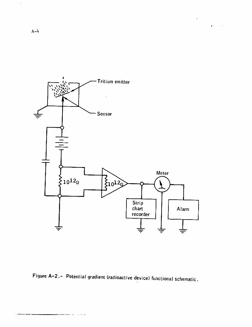
f
mQ
,,,,_ Trit,umemitter
_ Sensor
m
-g
m
Stripchart
recorder
±
Meter
Alarm
-____ __[__.- _.---
Figure A-2.- Potential gradient (radioactive device) functional schematic.

A-5
R 1
Whip antenna
\
___]___Recorderandalarm
l
_L
Direct current
operational
amplifier
Figure A-3.- Corona current detection system functional schematic.

A-6
Vertical whip antenna
East-west
loop antenna
Scopehorizontal
deflection
c i rcu its -._
North-south
loop antenna
circuit
(blanking circuitremoves 180 °
ambiguity)
Oscilloscope
\
\\ lloscopevertical
deflection
c ircu its
Figure A-4.- Sferic receiver functional schematic.

B-1
APPENDIX B
TECHNICAL NOTE*
EXPLORATION OF SOME HAZARDS TO NAVAL EQUIPMENT AND
OPERATIONS BENEATH ELECTRIFIED CLOUDS
by
M. Brook, C. R. Holmes, and C. B. Moore
New Mexico Institute of Mining and Technology
December 9, 1969
Revised
January 22, 1970
INTRODUCTION
The Apollo 12 launch at Cape Kennedy will probably be remembered as
one of the most exciting interactions of weather with a public event in
recent times. Thirty-six and one-half seconds after launch, at an alti-
tude of 6400 feet, the Saturn V vehicle was struck by lightning. At the
same time, no less than four cameras photographed a stroke to ground which
hit near the launch pad. The astronauts reported seeing a bright flash,
and later told of "feeling" the stroke. The fuel cells were disconnected
from the main power bus, an undervoltage condition prevailed, and numerous
alarms and warning lights were activated in the command module. Signal
conditioning equipment dropped out for a period of about 60 seconds.
About nine temperature and pressure sensors were permanently damaged.
At 52 seconds after launch a second major disturbance occurred. The
space craft was now at an altitude of 14,400 feet, 2,000 feet above the
freezing level. This time no visible evidence of lightning was photo-
graphed, but a spherics receiver at the ground was saturated. Equipment
malfunctions were again noted (battery power was in use at this time),
most noteworthy of which was the tumbling of the inertial measurement
unit in the spacecraft. Fortunately, the inertial unit was not providing
guidance at this time.
It is important to note that the Apollo 12 was not launched into a
thunderstorm, or cumulonimbus cloud. For six hours prior to launch, and
for a similar period afterward, no lightning strokes were observed or
recorded, and no thunder was heard. Electric field meters in the area
Prepared under Project Themis, Contract N 0001_-68-A-0157.

B-2
registered electric field magnitudes which are indicative of disturbedweather, but the Arthur D. Little lightning flash counter at nearbyPatrick AFBshowedno strokes except the one associated with the light-ning at 36.5 seconds after launch. It is most probable, therefore, thatthe passage of the vehicle through an electrified cloud incapable ofproducing lightning on its own, triggered the lightning flashes at 36.5seconds and 52 seconds after launch.
There is additional evidence, from an analysis of the telemetrysignals, that several other electrical disturbances of smaller magnitudeoccurred both before and after the two major events.
The Apollo 12 event brings to mind a similar occurrence involvingthe testing of depth charges by the Navy in ChesapeakeBay (Young, 1961).In this instance, a plume of water thrown up by the explosion to a heightof about 2h0 feet triggered a lightning discharge from the cloud above.Additional triggered lightning events have been reported associated withunderwater explosions during offshore seismic explorations. A more com-plete description of the ChesapeakeBay event, along with a descriptionof laboratory experiments of simulated triggered lightning has been pub-lished (Brook et al, 1961).
The Apollo 12 and ChesapeakeBay events cover the two most importantsituations which may be encountered in Naval Operations under electrifiedclouds. The similarity of the rapid emergenceof a water plume after anunderwater explosion to the launching of a Polaris missile is obvious.An aircraft flying through an electrified cloud would be expected tointeract with the cloud in a manner similar to the Apollo 12 event. [Anexcellent analysis entitled "Electrical Behavior of an Airplane in aThunderstorm" has been prepared for the FAAby Bernard Vonnegut (1965)I.Whether or not the triggered lightning reaches ground, and thereby ex-poses the rocket or aircraft to the destructive current and rate of riseof current observed in return strokes, is not a function of the vehicle,but of electrical conditions existing in the cloud. Weshall discusssomeof these considerations in what follows.
SOMEPROPERTIESOFLIGHTNING
For purposes of this report, and in the interests of brevity, weshall classify lightning discharges into three types.
i. Intracloud lightning. Lightning which does not connect to
ground, although dissipating amounts of electric charge and energy similar
to those that do, does not generally involve currents greater than
1,000 to 2,000 amperes with maximum rates of rise probably not exceeding100-500 amperes per microsecond. The average total duration of these
currents does not exceed 3 milliseconds.
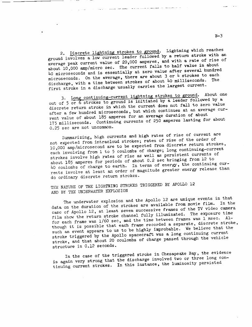
B-3
2. Discrete li6htning strokes to ground. Lightning which reaches
ground involves a low current leader followed by a return stroke with an
average peak current value of 20,000 amperes, and with a rate of rise of
about 10,000 amp/micro sec. 9he current falls to half value in about
h0 microseconds and is essentially at zero value after several hundred
microseconds. On the average, there are about 3 or h strokes to each
discharge, with a time between strokes of about 20 milliseconds. The
first stroke in a discharge usually carries the largest current.
3. Long continuing-current lightning strokes to ground. About one
out of 5 or 6 strokes to ground is initiated by a leader followed by a
discrete return stroke in which the current does not fall to zero value
after a few hundred microseconds, but which continues at an average cur-
rent value of about 185 amperes for an average duration of about
175 milliseconds. Continuing currents of 250 amperes lasting for about
0.25 sec are not uncommon.
Summarizing, high currents and high rates of rise of current are
not expected from intracloud strokes; rates of rise of the order of
10,000 amp/microsecond are to be expected from discrete return strokes,
each involving from 1 to 5 coulombs of charge; long continuing-current
strokes involve high rates of rise as well as persistent currents of
about 185 amperes for periods of about 0.2 sec bringing from 12 to
h0 coulombs of charge to earth. In terms of energy, the continuing cur-
rents involve at least an order of magnitude greater energy release than
do ordinary discrete return strokes.
THE NATURE OF THE LIGHTNING STROKES TRIGGERED BY APOLLO 12
AND BY THE UNDERWATER EXPLOSION
The underwater explosion and the Apollo 12 are unique events in that
data on the duration of the strokes are available from movie film. In the
case of Apollo 12, at least seven successive frames of the TV video camera
film show the return stroke channel fully illuminated. The exposure time
for each frame was 1/60 sec, and the time between frames was 1 msec. Al-
though it is possible that each frame recorded a separate, discrete stroke,such an event appears to us to be highly improbable. We believe that the
stroke triggered by the Apollo spacecraft was a long continuing current
stroke, and that about 20 coulombs of charge passed through the vehicle
structure in 0.12 seconds.
In the case of the triggered stroke in Chesapeake Bay, the evidence
is again very strong that the discharge involved two or three long con-
tinuing current strokes. In this instance, the luminosity persisted

B-4
throughout 65 frames taken at a rate of 64 frames per second. The dura-tion of this current was somewhatgreater than 1 sec, and probably in-volved a total charge of 100 coulombs or more.
It would be folly to conclude on the basis of only two events thattriggered lightning discharges to ground tend to be continuing currentdischarges. But other considerations also favor this view. Withoutgoing into too muchdetail, we point out that discrete lightning dis-charges must originate from regions of relatively high charge density,for the linear dimension of the charged volume appears to "be of theorder of 300 to 500 meters. Similar measurementson continuing currentdischarges give values for the linear dimension about 3 times greater.Since the volume is proportional to the cube of the linear dimension,cloud volumes associated with continuing currents are about 27 timesgreater than volumes storing charge for discrete strokes. On the otherhand, the ratio of the charges in continuing currents to discrete strokesis measuredto be from 2:1 to 6:1. Assuming that the charged volumes areat approximately the samepotential, the capacity of the volume drainedby the continuing current is approximately 3 times as large, consistentwith the 2 to 6 times greater charge stored. But the currents are roughlyin the ratio of 50 to 1. It is therefore apparent that the effective im-pedance of the current source is approximately proportional to the volumein which it is stored. It is this consideration which leads us to believethat triggered lightning probably involves volumes of charge whose densityis considerably below that which would lead to a natural discharge, andwould therefore exhibit a current consistent with the notion of a high in-ternal impedance.
There is obviously muchabout long continuing-current lightning, andthe disposition of charge in clouds which we do not understand. But onefact regarding the effective destructive potential of the long continuingcurrents is known. It has recently been shown, through correlated photo-graphic and electric field measurements, that the long continuing currentstrokes are the prime cause of lightning-associated forest fires. Notonly do they exhibit high rates of current rise in their initial phase,
but they persist long enough to cause considerable I_ heating damage.
ONTHEMECHANISMOFTRIGGERINGLIGHTNINGDISCHARGES
There is no doubt that considerable ionization is present in the hightemperature gases; the important question is how long do free electronspersist in sufficient numbersto render the exhaust gases conducting inthe appropriate sense. In lightning return strokes, where the temperaturemay reach 30,000OK, the air is almost fully ionized, and electron densi-
ties decay to values of approximately l02 cm-3 in about 50 milliseconds.The reason they persist for so long a time is that recombination is slowuntil the channel cools to about 3000°K. The temperature in a rocket

B-5
exhaust is about a factor of 5 or 6 less than in the lightning channel,and one expects therefore that free electron densities are initially verymuchless, and that their lifetime will also be muchless. At any rate,one can estimate with confidence that electron densities will effectivelybe zero after a time of the order of ten milliseconds following combus-tion. Certainly, in this sense, the absence of luminosity should be agood sign of the absence of free electrons.
On the other hand, there is no doubt that the rocket exhaust leavesbehind a trail of small and large ions, and that the net charge in thistrail is probably not zero. But these ions, which are elementary chargesattached to particulate matter, cannot be thought of as constituting aconductor in the samesense as free electrons, since the mobility of theions is more than an order of magnitude less than that of free electrons.
The presence of tons of particulate matter in the exhaust trail mayinfluence the path of a lightning stroke in other ways: The net spacecharge left behind on combustion products mayinfluence the course ofthe leader by providing an attractive or repulsive electric field. Also,the presence of materials in the exhaust may lower the ionization poten-tial of the air by acting as a "sensitizer". For example, sodium hasan ionization potential of 5.12 eV as comparedto nitrogen or oxygenatomic or molecular species which ionize at from 12 to 15 eV. If themechanismof progression of the leader involves photoelectric ionizationahead of it, then the lightning leader maybe "led" downthe exhausttrail in this way.
In general, one need not look for exotic mechanismsby which totrigger a lightning discharge if even moderate electric fields arepresent, such as are found in manyelectrified clouds not producinglightning. Consider a rocket such as the Saturn V, which is itself morethan lO0 meters long, and the luminous exhaust tail which at low alti-tudes appears to be at least _ or 5 times the length of the vehicle.About 600 meters is probably a good estimate for the total effectivelength of this conductor. If a thin conductor of this length is injectedrapidly into a region of electric field, it will tend to concentrate thefield lines at its extremities, and if the concentration factor is largeenough, the electric field at these points will exceed the breakdown fieldof air. The conductor will then go into corona, and if the electric fieldis strong enough, the corona streamers will continue to propagate outalong the field lines.
To estimate the concentration factor of a long conductor in a uniformelectric field, we can approximate its shape by a prolate spheroid. Theproblem is then one of finding the electric field distribution at thesurface of the conductor extremities in terms of the ambient electric

B-6
field Eo. For a vehicle such as the Apollo 12 plus its luminous tail,
we calculate that the electric field at the tip of the rocket head isgiven approximately by
n + 1 1
E = E° no in -- - ,
1
where n = (1 - b2/c 2) 2o , and b and c are the semiminor and semimaJor
axes, respectively. Setting E equal to the breakdown field Ebr, the
ambient field E becomes the critical field E at which breakdown ensues0 C "
Thus KEc = Ebr' where the enhancement factor K is given by
I IIK = no)(no2-1) 2 in + _ 1
In Table l, we have listed the critical field values corresponding to di-
mensions of rocket vehicles such as Apollo 12, and to other smaller vehi-
cles which may be deployed in various naval operations.

B-7
Table i. Concentration factor E/E ° = K, critical field Ec, for
equivalent semimaJor axis c, and semiminor axis b, at a pressure alti-
tude of 6,000 feet, where the breakdown field is assumed to be 24000 V/cm.
c(Meters) b(Meters) E/E o = K Ecrit(Volts/cm)
ll 1 57 420
27 0.5 790 30
i00" 5* 320* 75*
3O0 5 95O 25
*The Apollo 12 was capped with a hemisphere of radius I0 cm. This
curvature is greater than the maximum curvature for the ellipsoid as-sumed. Both the concentration factor K and the critical field Ecrit
were calculated in this instance using the higher value for the curvature.
The maximum curvature at the tip of a prolate spheroid is related to the
c/b ratio by c/r = c2/b 2, where r is the radius at the tip.
Field values larger than 20 V/cm have been reported for clouds only sev-
eral thousand feet thick. We see clearly that a long conductor injected
into an electric field of only moderate intensity (25 V/cm) will con-
centrate the lines of force sufficient to produce breakdown. Magnitudes
of electric fields observed in clouds are discussed in another section
of this report.
For the benefit of the reader who may want to calculate enhancement
factors for c/b ratios other than those given in Table l, we have plotted
in Figure 1 a curve of enhancement factor K vs the ratios c/r = c2/b 2.
Here r is the radius of curvature at the ends of the prolate spheroid.
When an exposed conductor at rest emits corona, a space charge which
acts to reduce the field, is formed around the emitting point. This ac-
tion serves to limit the flow of current and exhibit further breakdown.
In the presence of wind the space charge is carried off, and higher cur-
rents can flow that again tend to reduce the field below breakdown. When
the wind speed gets hig_h enough, or when the conductor is a rocket moving
at more than about 100 m/sec, the air motion relative to the point can be
greater than the electron drift velocities. Consequently, the exposed
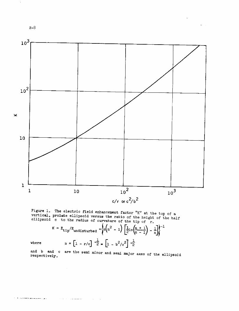
B-8
10 3
2i0
I0
I0 10 2 10 3
c/r or c2/b 2
Figure i. The electric field enhancement factor "K" at the top of a
vertical, prolate ellipsoid versus the ratio of the height of the half
ellipsoid c to the radius of curvature of the tip of r.
K = Etip/Eundisturbed =In(n2 - I) llln(___I - lll-1
where
and b
1 1
n = El-r/c] -_= El-b2/c 2] -_
and c are the semi minor and semi major axes of the ellipsoidrespectively.

B-9
point is no longer shielded from the high field by the emitted charges,
and a lightning discharge may be initiated.
Whether or not a vehicle such as Saturn V will become involved in a
lightning discharge depends also upon the amount of charge stored in the
neighboring cloud volume. We have seen that the initiation of corona is
highly probable in moderate electric fields; once corona occurs the dis-
charge will continue if the charge density at the tip of the streamer can
be maintained at a high enough value. Once a streamer forms and propagates
into the charged volume, another streamer will also propagate from the otherend of the vehicle. The formation of a streamer and the maintainance of a
breakdown field at the streamer tip requires that charge be continually fed
into the growing streamer to charge its increasing capacity. If the cloud
capacity is large enough, the flow of charge from it necessary to maintain
the breakdown field at the streamer tip will not lower appreciably the po-
tential of the region, and the developing streamer will be led along the
lines of force to either another charged volume of opposite sign in the
cloud, or to ground. On the other hand, if the amount of charge availableor remaining in the cloud is not sufficient to maintain the streamer tips
at breakdown, the discharge will cease.
Numerous investigations have been made on the amount of electrical
energy which various types of structures can withstand without damage.
The energies shown in Table 2 have been calculated as available from a
volume of cloud for various electric field values at its surface. For
simplicity, a volume of uniform charge density in the form of a sphere
of radius a has been assumed.

B-IO
Table 2. Available Energy W, in Joules, from space charge storedin a spherical volume of cloud of radius a, with electric field, Eat its surface.* a'
Ea (V m-1) a (Meters) W (JOULES)
102 102 0.67
102 3 × 10² 18
102 103 6.7 × 10²
102 3 x 10³ 1.8 × 10⁴
104 102 6.7 x 10³
104 3 x 10² 1.8 x 10⁵
104 103 6.7 x 10⁶
104 3 x 10³ 1.8 x 10⁷
106 3 x 10² 1.8 x 10⁹
106 5 x 10² 8.1 x 10⁹
3 × 10⁶ 3 x 10² 1.6 × i0 I0
3 × 10⁶ 5 x 10² 7.5 x i0 I0
*Natural lightning stroke energies are in the range of 10 8
to l0 l0 Joules

B-II
THEEFFECTOFCHARGEONTHEROCKETIN THEABSENCE
OFANEXTERNALELECTRICFIELD
A rocket maybecomecharged in the absenceof external fields byvarious mechanisms. The maximumcharge will be acquired whenthe electricfield at the point of largest curvature exceeds the breakdown field.
Wecan estimate the total energy available under these conditionsfrom an estimate of the capacity of the vehicle, using a value of
2.4 x l06 V/M for the breakdown field.
The capacity of a rocket can be estimated by again approximatingits shapewith a prolate spheroid. The capacity is given approximatelyby
C = 4_E c _arc tanh (1 - b2/c2)1/2_ -1o
To find the maximumcharge which can be acquired by the rocket wecalculate the maximumvalue of the field at its surface; this value occursat the ends of the prolate spheroid:
= l0 -10 b2.Qmax 1.1 x Emax
6
Since E will be the breakdown field, we can set EBr 2.4 x l0 V/M,max
corresponding to breakdown at a pressure height of 6,000 feet. Thus,
Qmax = 2.64 x l0-h b 2. The maximum energy which can be stored on the1
rocket is then given by W = _ Q2/C.
In Table 3 we give the values calculated for capacity, maximum
charge, and maximum energy for the four rocket dimensions calculated
previously.

B-12 •
Table 3. Maximumcharge Q, capacity C, and maximumenergy W, foreffective rocket dimensions c (semimaJor axis) and b (semiminor axis).
c (Meters) b (Meters) C (Farads) Qmax(COulombs) W (Joules)max
ii i 4 x i0 -i0 2.7 x 10⁻⁴ 91
27 0.5 6.4 x I0 -I0 6.7 x 10⁻⁵ 3.5
i00 5 3 x 10⁻⁹ 6.7 x 10-3750O
300 5 7 x 10 -9 6.7 x 10 -3 3200
It is obvious that the maximum charge which can be carried by a
rocket is trivial compared with the charge transferred by lightning which
varies from 3 to hO coulombs. In addition, the amount of electrical
energy stored on a rocket is at least 5 orders of magnitude less than isinvolved in lightning flashes.
On the other hand, charge stored on a rocket entering a region of
electric field will lower th9 threshold for breakdown and the triggering
of lightning. Unfortunately, there are no available measurements of the
charge carried by rockets to estimate this effect. Similarly, there are
no values available for the atmospheric electric perturbations caused bythe firing of a rocket and its passage through the atmosphere.
METHODS OF SENSING HIGH ELECTRIC FIELDS IN CLOUDS
For several reasons, the electric field intensities seen at the
earth's surface are generally smaller than those encountered within
clouds: The charge within and around clouds usually occurs in both
polarities so that the electric field seen at the surface of the earth
is the superposition of opposing fields. The observed field intensity
therefore usually has an appreciably lower magnitude than that pro-
duced by either polarity of charge alone. Furthermore, each charge in
the atmosphere and its image within the earth comprise an electric di-
pole; the intensity of the electric field decreases with the cube ofthe distance from the observer to the dipole.
Another field reducing effect is the formation of a screening layerof charge at the edge of clouds caused by capture of ions moving from
the clear air under the influence of the electric fields produced bycharges within the cloud.

B-13
For these reasons the electric fields seen at the surface of the-i
solid earth are rarely much in excess of i00 V cm even at the time
just before lightning occurs nearby. On the other hand, immediately
after a discharge, the field may be reversed and exhibit values of a
thousand volts/cm -I decaying in a few seconds to the value observed
before lightning occurred.
From various measurements it appears that electric field inten-
sities within electrified clouds may often be as great as several
-ithousand volts cm With data from sparks produced in the laboratory,
10 4 -ione would expect that fields as great as V cm may be necessary
to initiate lightning naturally within such clouds.
To sense the intensity of electric fields within clouds several
techniques may be used:
1. Penetrations with instrumented rockets.
Dr. W. P. Winn of the National Center for Atmospheric Research
has devised and used successfully electric-field sensitive instruments
which are carried on spinning rockets to altitudes of about 20,000 feet
above sea level. The radial components of any electric field vector
produce a displacement current in the rockets. As the rocket rotates
a sinusoidal signal is generated which is proportional to the external
electric field and essentially is unaffected by charge on the rocket.
The signal is telemetered back to earth with a low-power FM transmitter
using the rocket itself as the antenna. In preliminary measurements,-1
electric field intensities of up to 700 V cm have been observed in
electrified clouds. The maximum electric fields measured during the
same period at the surface of the earth Just below these clouds did not
-1exceed lO0 V cm
2. Measurement from instrumented aircraft.
Airplanes may be equipped with devices to measure the intensity and
direction of the atmospheric electric field, but this is a difficult
problem inside thunderstorm clouds. A large part of the difficulty
arises from charge that the aircraft acquires in flight by the action of
the engines, collisions with particulate matter (aerosol particles, cloud
droplets, rain and snow) and by point discharge under high electric fields.
The presence of an airplane distorts and concentrates the atmospheric
electric field so that extensive adjustments and calibrations are neces-
sary to use the instruments in clear air. Within electrified clouds the
difficulties of interpreting the measurements are even more formidable
due to the charge transfers between the moving plane and cloud particles,
and, if point discharge occurs from propellors, wing tips, or jet ex-
hausts, the calibrations made in clear air may no longer be valid.

B-I4
To measure the atmospheric electric fields with an airplane one mustprovide in essence two field sensing devices for each componentof theelectric field and then subtract their adjusted outputs. This processrequires the installation and operation of 6 field sensing devices formeasurementof the 3 field components, although somerecent ingeniousdevices designed by Dr. H. Kasemir of ESSA,Boulder, haye reduced thisnumber to three.
Indications of high electric fields within clouds have been obtained
with aircraft by Gunn and Fitzgerald who report values as great as
3,000 V cm -I.
3. Balloon-borne sensors.
Many of the difficulties encountered in determination of the elec-
tric field intensities within clouds arise from the motion of the ve-
hicle transporting the instruments. These difficulties can be minimized
by the use of balloons, free or captive, to carry field measuring devices
into electrified clouds. Measurements made in this manner are limited
to one region or one penetration of a cloud but this limitation may beacceptable for research purposes.
During the summer of 1969, in an effort to determine the range of
maximum electric fields within clouds, C. B. Moore mounted an electric
field mill inside a spherical electrode from a Van de Graaff high-
voltage supply. The mill was recessed, facing downward, in the re-
entrant portion of the electrode so that no sharp points protruded to
produce corona at low fields. Signals from the field mill were pre-
served on a small portable tape recorder also mounted within the sphere,
thus eliminating the telemetry antenna which is usually a good source
of corona. This instrument was carried into electrified clouds be-
neath a captive balloon and obtained indications of electric field
intensities at the surface of the sphere in excess of 12,000 V cm -1
The conducting sphere concentrates external fields by a factor of 31
the field intensity indicated also varies with the angle e that the
external field E makes with the suspension axis of the sphere Theo
resultant of these two factors is to produce an indicated intensity
Eindicate d = 3E° Cos e.
If we assume a vertical external field and correct for the concen-
trating effects of the housing, the measurements made during the summer

B-15
of 1969 indicate undisturbed electric field intensities in the cloudsin excess of 4,000 V/cm.
These measurementswith a single mill could not discriminate be-tween the field indication produced by external electric fields andthose arising from charge trapped on the spherical electrode. The meas-urements will be repeated with a new system that uses two improved fieldmills in a similar spherical housing from which one mill will look ver-tically, as at present, while the other will look horizontally. Thewhole system will be caused to rotate slowly so that a modulation on thehorizontally looking mill will be produced that is proportional to thehorizontal componentof the external field multiplied by the cosine ofthe azimuth angle. The horizontal componentof the electric field willthen be given by a sinusoidally varying function superimposed on a D.C.component, the D.C. componentresulting from any net charge collectedon the surface of the sphere. The measuredvalues of the vertical andhorizontal electric field componentsand the self-charge-induced D.C.-offset will permit both correction of the magnitudes of the field com-ponents and a determination of the charge collected on the instrument.
This instrument is not suitable for use in naval operations but canbe invaluable in the collection of information about cloud electrification.
4. Radar sensin_ of electric fields in rain clouds.
The introduction of measuring instruments into electrified clouds
distorts the natural electric fields; often the field intensity measured
is limited by the presence of the instrument which itself causes dielectric
breakdown of the air and the release of charge resulting in spurious
readings. To measure the maximum fields that exist in clouds one needs
to sense -- remotely and without the introduction of instruments
the presence of the electric field within clouds.
One method now under investigation for accomplishing this is the
measurement of the distortion of raindrops in clouds. Raindrops are
deformed in the direction of the electric field. Water drops are
essentially good conductors containing sufficient charge carriers, even
when neutral, to polarize in the presence of a field. The action of
the field is to cause positive charge to move in one direction and
negative charge to move in the opposite direction. When the field is
sufficiently intense these forces cause physical deformation of the
drop along the field direction such that an elongated drop is pro-
duced. If the intensity of the field is increased sufficiently, the
drop can actually be disrupted by the action of the electric forces.
The drop distortion in a volume of cloud can be sensed with a
radar. A raindrop illuminated by a microwave pulse of electromagnetic
B-16
radiation reflects or "back-scatters" radiation that is roughly pro-portional to the drop dimension in the direction of the incidentelectric vector. If the incident electric vector is rotated througha complete turn about the line of sight, the back scattered radiationwill vary in intensity as the direction of the electric vector is firstalong the maximumdrop dimension and then along the minimumdimension.Frommeasurementsof the cloud reflectivity and the amplitude of the"cross-polarized" back scatter it appears that the magnitudes and di-rections of the electric fields in clouds maybe inferred by remotemeans. This procedure has promise, and a radar with polarization di-versity is now under construction at New Mexico Tech.
Another radar technique for remote sensing of electric fields is
also presently under development. Raindrops are excited into oscil-
lation as they fall, and the changing cross section of a vibrating dropappears as a true amplitude modulation of the back scattered radar
signal. This effect has been demonstrated in the laboratory with drops
freely suspended in a vertical wind tunnel. The natural frequency of
vibration is related to the drop size, surface tension, and also to the
electric field, since the electric field produces a stress on the drop
surface in opposition to surface tension forces, thus altering the
effective spring constant. Studies of how the presence of an electric
field alters the drop vibrational frequency are underway. The shift in
the drop vibrational spectrum, for example, before and after a light-ning stroke, may be used to infer electric field values.
COMPARISON OF CONTINENTAL AND MARITIME ATMOSPHERIC ELECTRIC FIELDS.
The energy that can be released by a lightning discharge from an
electrified cloud increases with the cloud volume and with the square of
the maximum electric field. Over the land the atmospheric electric field
measured at the surface is limited by discharge currents arising from
grounded points. Under high electric fields, exposed conducting points
such as grass, trees, and structures concentrate the electric field to
such an extent that air around the points becomes ionized. This permits
electric currents to flow from the earth and acts to reduce the electric
-1stress. When the electric field intensity exceeds about l0 or 15 V cm ,
currents in excess of one microamphere can flow from each point. As a
result, electric field intensities in the air near the earth beneath
thunderstorms are limited and rarely exceed values in excess of 100 V cm -1
Perhaps for this reason repeated attempts at New Mexico Tech to trigger
lightning by injecting wire-trailing rockets into thunderstorms over land
have been unsuccessful. The Apollo 12 vehicle is the only rocket of which
we are aware that has triggered lightning at low altitudes over landsurfaces.
B-17
In contrast to this are the successful initiations of lightning byDr. M. M. Newmanof the Lightning and Transients Institute who fired wire-trailing rockets from a small vessel off the Florida coast. The resultinglightning was often initiated when the rocket was no higher than i00 metersabove the water; this suggests to us the existence of a high electric stressover the water surface.
It is perhaps worth noting that evidence is also available from an-tiquity that indicates the presence of especially high electric fieldsover water surfaces during disturbed weather: St. Elmo's fire is one re-sult of intense point discharge. It is true that point discharge can occurwithout muchvisible luminosity, but noticeable St. Elmo's fire is indic-ative of intense point discharge and very high electric fields.
Our meBsurementsof the point discharge currents from the mast of anLSMoperating on the Atlantic Missile Rangeindicate values that are tentimes those flowing from a similar installation on the beach of GrandBahamaIsland. From these observations we may infer that the electricfield intensities under thunderstorms over water surfaces are similarly
enhanced. To investigate this effect further, we have attempted the
direct measurement of electric fields beneath thunderstorms over the ocean
with instrumented aircraft. The field intensities encountered were much
higher than those over land, but the data were confused by saturation of
the measuring instruments in the very high fields and by the effects of
splashing raindrops which charged the aircraft.
Better measurements are needed, but we know enough to state that the
potential for the triggering of lightning and for the release of stored
charge is much higher over the oceans than it is over land. For this
reason, a large rocket injected from beneath a water surface into a region
of high electric field has a high probability of initiating lightning and
becoming part of the conducting channel.
The apparent absence of corona points over the ocean surface probably
accounts for the existence of high fields, but there is no adequate de-
scription of the atmospheric electric processes over the ocean duringdisturbed weather. In general, little is known about thunderstorms over
oceans: we know nothing about the distribution of charge or the polarity.
In addition, we don't know whether such thunderstorms are electrically
more vigorous because of the low point discharge emission, or whether they
are less vigorous because of it.
The atmospheric electric state produced by convective clouds over the
water and its possible effects on ocean launching sites can at best be a
subject of speculation at the present time. Definitive studies in elec-
trified clouds and in the air above the oceans are sorely needed. Such
studies should include instrumented aircraft flights over, through, and
B-18
under clouds, instrumented rocket penetrations, and studies of the sequenceof electrical events as seen from the surface beneath oceanic thunderstorms.Measurementsof the visual and radar thickness of clouds should be correlatedwith the electric field and other measurementsto help develop criteria use-ful for establishing minimumhazard situations.
SUGGESTIONSFORMINIMIZINGHAZARDSIN OPERATIONALPROCEDURESUNDERELECTRIFIEDCLOUDS
i. On the basis of the Apollo 12 experience, it is mandatory that theelectronic sensing and computing elements of guidance systems be madeimmuneto lightning transients.
2. Although no lower limit to cloud thickness can presently be given,
we might guess that vehicle penetration into clouds less than 6,000 to8,000 feet thick constitutes a minimal hazard situation.
3. Whenever possible, probing by aircraft or small sensing rocket
penetration into clouds thicker than 5,000 feet should precede vehiclelaunches.
4. Whenever possible, radar evaluation of rate of echo growth as a
measure of potential convective and electrical activity should be made.
5. Short range sferics detectors and lightning flash counters should
be employed to warn of the occurrence of nearby lightning. Lightningtransients may be detectable even from below the ocean surface.
6. The measurement of point discharge current at the surface (as a
simple means of detecting high electric fields before lightning has oc-
curred) should be made in all cases when clouds are present.
SUGGESTION FOR DESIRABLE STUDIES
1. Development of remote sensing techniques for the study of elec-
tric fields in clouds over the ocean must be implemented. The technique
of cross polarization analysis of radar returns is promising. Similarly,
optical polarization measurements of cloud surface reflected light may beindicative of electric fields strong enough to orient crystals near the
surface. Such a technique could be utilized both from surface measure-
ments as well as from aircraft. Other means of remote measurements of
fields in clouds should be explored. Particular attention should be given
to the exploration of new methods suitable to ocean vessel utilization.
2. Further development of small rocket probing techniques is needed.
This method may well be the only simple technique available for measuringelectric fields in clouds in times of emergency. In addition to the de-
velopment of instrumentation, a program using these rockets to uncover
electric field intensity versus cloud thickness relationships should beundertaken.

B-19
3. Lightning triggering experiments over the ocean should be madewith the intent of exploring the possibility of relieving the electricstress in clouds prior to a launch. A trailing wire on a rocket mightbe used. Again, cloud thickness and electric field measurementsshouldbe madesimultaneously. The nature of the triggered, lightning strokeand continuing currents over the ocean should be studied using high-resolution field-change instruments and high-speed cameras.
4. The charge carried on operational vehicles should be measuredduring test firings, along with the space charge left behind and the con-ductivity in the rocket exhaust.
5. A determination of the maximumelectric fields existing over theocean surface should be madefor all weather conditions. Wesuggest that,since surface vehicles distort the electric field and often produce coronaby their presence, a submarine would be ideal for such measurements. Greatcare should be taken to eliminate point discharge from the measuring in-strument and its support.
6. Laboratory studies, using modeling tanks with water surfaces invarious stages of agitation, should be initiated to study the electricalbehavior of water surfaces under high electric stress.
7. A very general study of thunderstorm properties over the oceanand how they differ from storms over land is needed. Such information isessential in projecting what we now know about storms over land to oceansituations.
REFERENCES
Brook, M., G. Armstrong, R. P. H. Winder, B. Vonnegut, and C. B. Moore
(1961) Artificial Initiation of Lightning Discharges, J. Geophys.
Res., V-66, pp 3967- 39699.
Vonnegut, B. (1965) Electrical Behavior of an Airplane in a Thunderstorm,Technical report FAA -ADS_3_, prepared for the Feder_--Aviation
Agency, Aircraft Development Service under Contract FA64WA-5151 with
Arthur D. Little, Inc., Cambridge, Mass.
Young, G. A. (1961) Lightning strike to an underwater explosion plume,
U. S. Naval Ord. Lab. Report 61-h3.

_r

C-I
APPENDIX C
CIRCUIT ANALYSIS
This appendix is an analysis of spacecraft circuitry.
Automatic Abort System Circuit Analysis
The emergency detection system wire routing in both the service
module and spacecraft adapter is in close proximity to the skin (see
fig. C-I), and therefore could be considered susceptible to induced
voltage and current in the emergency detection system voting circuit.
The analysis assumes a lightning current of I0 000 amperes with a i _sec
rise time with a duration of i0 _sec. A further assumption is that
i0 percent of the total current is concentrated under the emergency de-
tection system wiring in the spacecraft adapter. With these conservative
assumptions, the model for the emergency detection system voting logic
power circuit inductive coupling is as follows:
_'---Skin
----_I00_
The induced electromotive force c in the circuit is determined by
R2 di-E._- x in2w RI dt
-7where Po = 4w x i0
I = 30 feet = 9.15 meters
R2 = 3 centimeters
RI = 0.3 centimeters
By applying the limiting factor
di i x i0 4 amperes x 0,i
_-- i x 10 -6 sec
= i x 109 _-_sec

C-2 °
then
4_ × 10-7(9 15) 3 =2w " X in _ x lO 9 42 x i0 2 volts
therefore
42 x 102
i x 102= 42 amperes for i0 usec
This voltage level may result in insulation breakdown, however, because
of the short duration, the operation of the emergency detection system
should not be affected. The closed relay contacts in the instrumentunit would not be affected by the 42 amperes for i0 usec.
Ordnance Circuit Analysis
The effect that an electrical discharge would have on the pyrotechnic
system was evaluated in the following areas: voltages induced on the
single bridgewire Apollo standard initiator (pin to pin or pin to case)
and voltages induced on the pyrotechnic initiating circuitry itself caus-
ing inadvertent operation. The design characteristics of the system areshown in table C-I.
The following analysis indicates the probable magnitude of the in-
duced voltage and currents in the initiator circuitry. The canard deploy
system was selected the most susceptible circuit because the initiator
wiring is in close proximity to the skin for a long length (see fig. C-2)
and the current density is greatest on the tower since the skin cross sec-tional area is the least of the complete stack.
The following compensating factors were used to provide a more real-istic analysis.
a. The current will not be concentrated under the initiator circuit(lO to 1 reduction)
b. Shielding will provide attenuation at the frequency assumed forthe electrical discharge (lO to 1 reduction)
c. The initiator circuitry has twisted wires which provide a cancel-ling effect (i0 to i reduction).

C-B
The model for the canard deploy initiator circuit inductive coupling
is as follows:
Analysis (pin to pin):
--g[---
The induced electromotive force _ in the circuit is determined by
R2 di
2_ RI dt
where _o = 4w x 10 -7
= 26 feet = 7.8 meters
R2 = 0.6 centimeters
RI = 0.3 centimeters
By applying the limiting factors
di _ i 10 4 amperes x i0 -3x _= i x i0 7 sec
d-_- -- i x 10 -6 sec
t h en
o.6_ × 1o-7(V'8°) x In 5q_.B
e = -- 2_
x i0 7 = i0.8 yolts
If the line resistance and inductance are neglected, the voltage
will divide equally between the fuse resistor and the initiator or approx-
imately 5 volts. This represents a power of approximately 25 watts for
i0 _sec.
The pulse energY non_susceptibility of the initiators has been demon-
strated to 1225 watts for i0 _sec.

c-4
The probability of inadvertent operation of the pyro initiating cir-
cuits is remote since all wiring is within the command module and is not
in close proximity with the external skin. Even if the induced voltage
was of sufficient magnitude, the duration of electrical discharge (micro-
seconds) and induced voltage is not sufficient to pull in relays (milli-seconds).
TABLE C-I.- SINGLE BRIDGEWIRE APOLLO STANDARD
INITIATOR CHARACTERISTICS
Max no-fire current _ i amp for 5 minutes
Max no-fire power - 1 watt for 5 minutesMax all-fire current _ 3.5 or greater
Continuity current _ 25 applications of 50 ma for 1 min eachThermal _ h00 o F for 1 hour
Insulation resistance _ 2 megohms at 250 volts dcDielectric strength _ 200 vac for 1 minute
Electrostatic sensitivity _ 25 000 v discharge from 500 mmfcapacitor
Duddin_ characteristic
Ignition m_x precludes dudding. No dud experienced in all teststo date.


c-6
Canard
Pitch control motor
Jettison motor
Launch escapemotor
I II I
Figure C-2.-Tower pyrotechnic wire routing.
NASA _ MSC
MS(; 44 )'4 "70
k

ew,.4 _ ov-_
¢+.,
Reproduced by NTISNational Technical Information Service
U.S. Department of CommerceSpringfield, VA 22161
This report was printed specifically for yourorder from our collection of more than 1.5
million technical reports.
For economy and efficiency, NTIS does not maintain stock of its vast
collection of technical reports. Rather, most documents are printed for
each order. Your copy is the best possible reproduction available from
our master archive. If you have any questions concerning this document
or any order you placed with NTIS, please call our Customer Services
Department at (703)487-4660.
Always think of NTIS when you want:
• Access to the technical, scientific, and engineering results generated
by the ongoing multibillion dollar R&D program of the U.S. Government.
• R&D results from Japan, West Germany, Great Britain, and some ZO
other countries, most of it reported in English.
NTIS also operates two centers that can provide you with valuableinformation:
• The Federal Computer Products Center - offers software and
datafiles produced by Federal agencies.
• The Center for the Utilization of Federal Technology - gives you
access to the best of Federal technologies and laboratory resources.
For more information about NTIS, send for our FREE NTIS Products
and Services Catalog which describes how you can access this U.S. and
foreign Government technology. Call (703)487-4650 or send this
sheet to NTIS, U.S. Department of Commerce, Springfield, VA 22161.
Ask for catalog, PR-827.
Name
Address
Telephone
=_ - Your Source to U.S. and Foreign GovernmentResearch and Technology.