National Instruments Labview Software Fire Alarm ... · Course that uses LabVIEW and is taken by...
14
Fire Alarm Laboratory Class using LabVIEW Software taken by Students from Two-Year Colleges Prof. Harry Franz, P.E. 1 University of Houston- Downtown Member ASEE, IEEE, ISA. NSPE, TAP Abstract The purpose of this paper is to discuss the creation of a Safety and Fire Alarm Laboratory Course that uses LabVIEW and is taken by students that originate from two-year colleges. The University of Houston – Downtown in Houston, Texas has recently instituted a Safety and Fire BSET program. One of the courses in the program is the “Fire Alarm” course. The challenge has been to create a laboratory that is within both budget and academic constraints, and which could be taken by a diverse mix of students from a variety of two-year colleges. The “Fire Alarm” course laboratory requires the use of both software and hardware. The class students mostly work in a profession that is related to fire and safety. They are fire personnel, safety designers, and are of other related technical backgrounds. The students in the Fire Alarm course, however, have a greatly mixed level and background in math, computer science, and other academics. The lab equipment and software must be readily useable to allow coverage of all material in the course in the time allocated. The LabVIEW software creates a laboratory that is within budget constraints and that is readily available and usable by students from two-year colleges that have differing academics. The software is used to both create standalone projects, and to design and interact with course hardware projects. Innovative laboratory exercises to acquaint the safety and fire students with LabVIEW are used in the “Fire Alarm” course. The exercises both familiarize the students with the use of LabVIEW and the subject area of alarm systems. The alarm systems software exercises incorporate the detection of fire signatures that include smoke, heat, and other changes in ambient conditions. The exercises also include the logic to activate alarms and fire suppression. Use of both digital logic and analog functions and systems are included in the exercises. The exercises for the alarm systems laboratory start with very basic electrical and logic concepts that use fundamental LabVIEW features. The exercises quickly progress to more advanced concepts and advanced LabVIEW features. The students enjoy the software use and create colorful practical designs of panels and systems. The final course project design requires a working knowledge of both LabVIEW and alarm systems concepts. Details of the innovative lab exercises that were created to help the Alarm System course students of mixed academic levels and backgrounds, to become proficient in the LabVIEW software, will be given and discussed. In addition, the outcome of the final courses projects the students designed and implemented are given in the addendum at the end of this paper. --------------------------------------------------------------------------------------------------------------- 1 Associate Professor Control & Instrumentation Electronics Design and Safety & Fire Engineering Technology, UH-Downtown, Houston, Texas, 77002 Page 9.939.1
Transcript of National Instruments Labview Software Fire Alarm ... · Course that uses LabVIEW and is taken by...

Fire Alarm Laboratory Class using LabVIEW Software
taken by Students from Two-Year Colleges
Prof. Harry Franz, P.E.1
University of Houston- Downtown
Member ASEE, IEEE, ISA. NSPE, TAP
Abstract
The purpose of this paper is to discuss the creation of a Safety and Fire Alarm Laboratory
Course that uses LabVIEW and is taken by students that originate from two-year colleges.
The University of Houston – Downtown in Houston, Texas has recently instituted a Safety
and Fire BSET program. One of the courses in the program is the “Fire Alarm” course. The
challenge has been to create a laboratory that is within both budget and academic constraints,
and which could be taken by a diverse mix of students from a variety of two-year colleges.
The “Fire Alarm” course laboratory requires the use of both software and hardware.
The class students mostly work in a profession that is related to fire and safety. They are
fire personnel, safety designers, and are of other related technical backgrounds. The students
in the Fire Alarm course, however, have a greatly mixed level and background in math,
computer science, and other academics.
The lab equipment and software must be readily useable to allow coverage of all material
in the course in the time allocated. The LabVIEW software creates a laboratory that is within
budget constraints and that is readily available and usable by students from two-year colleges
that have differing academics. The software is used to both create standalone projects, and to
design and interact with course hardware projects.
Innovative laboratory exercises to acquaint the safety and fire students with LabVIEW are
used in the “Fire Alarm” course. The exercises both familiarize the students with the use of
LabVIEW and the subject area of alarm systems.
The alarm systems software exercises incorporate the detection of fire signatures that include
smoke, heat, and other changes in ambient conditions. The exercises also include the
logic to activate alarms and fire suppression. Use of both digital logic and analog functions
and systems are included in the exercises.
The exercises for the alarm systems laboratory start with very basic electrical and logic
concepts that use fundamental LabVIEW features. The exercises quickly progress to more
advanced concepts and advanced LabVIEW features. The students enjoy the software use
and create colorful practical designs of panels and systems. The final course project design
requires a working knowledge of both LabVIEW and alarm systems concepts.
Details of the innovative lab exercises that were created to help the Alarm System course
students of mixed academic levels and backgrounds, to become proficient in the LabVIEW
software, will be given and discussed. In addition, the outcome of the final courses projects
the students designed and implemented are given in the addendum at the end of this paper.
--------------------------------------------------------------------------------------------------------------- 1
Associate Professor Control & Instrumentation Electronics Design and Safety & Fire
Engineering Technology, UH-Downtown, Houston, Texas, 77002
Page 9.939.1

sheet two
The University of Houston–Downtown (UHD) in Houston, Texas, Safety and
Fire BSET program is about three years old. An important course that is part
of the UHD Safety and Fire program is the “Fire Alarm” course. The course
formal catalog name is “Fire Suppression and Detection Systems”. The
formal catalog description includes operational capabilities and utilization
requirements of fire detection and signaling systems, fire detection and
suppression applied in practical problems, and experimental demonstrations
and computer simulations. The purpose of the “Fire Alarm” course is to
acquaint each student with the detection, logic, alarm, and suppression
systems used for fire protection.
The course with materials at the junior level is taken by a diverse mix of
students that originate from two-year schools with a variety of levels of
math, electrical theory, logic, and software use. The students are also from
within the University of Houston-Downtown itself and often are taking a
double major.
It has been a challenge to create a laboratory for the alarm course that is
within budget and that includes proper software and hardware. The projects
have been built and developed by the students through the use of National
Instruments LabVIEW software and respective hardware. The completed
projects are used as training devices.
It also has been a major challenge to create course projects for the fire alarm
laboratory because the level of academics of the students is quite varied, even
though most of them work in a profession that relates to fire and safety. The
majority of the students are fire personnel and safety designers, and the others
have an assortment of technical backgrounds.
The basics of electrical, digital logic and analog design are first covered
in the “fire alarm” course to either to form a solid basic understanding or
to reinforce prior knowledge. Understanding of the basics is accomplished by
using circuit simulation software exercises and LabVIEW exercises.
The exercises are readily completed by the students, even though the student
body is greatly diverse, through numerous classroom detailed instruction and
classroom examples. The exercise assignments are to an extent self-paced
and vary from the very basic to advanced levels.
Page 9.939.2

sheet three
The alarm course circuit simulation software instruction starts with the
students becoming acquainted the elements and symbols by using the software
menus. An advantage of the menus is that each symbol when touched, gives
the name of the symbol. The symbols are quickly learned and when used
in conjunction with classroom circuit examples, students are readily able to
complete the related circuit software exercises.
The use of basic circuit simulation software exercises includes resistors, and
series, parallel, and combination circuits. Digital logic basic exercises include
logic gates and combinations. Analog functions are introduced. Relays and
ladder logic are given. The uses of retentive and non-retentive circuits are
explained. Types of alarm circuit latches are covered.
The LabVIEW software instruction starts with an introduction to the front
view or panel view. Elements for the panel are obtained from the control
menu. It is noted to the students that this view is for the layout of devices.
The menus are used to learn the name and use of each item. It is emphasized
to the students that each device can be designated for use as an input or
output. Uses of tools of the tool menu for the panel view are then given.
The back view or connection diagram is covered next. Use of the tool menu
as it is used for the connection diagram is given. The wiring of the devices on
the diagram is then demonstrated to the students.
A tie-in between front panel view and back connection diagram is made.
Instructions and examples are given in the use of the menus for device
designation as either an input control or output indicator, and for use of color
choice, connection wiring, and other tools. The LabVIEW software quickly
and clearly points out any errors and suggests how to correct them. Because
the LabVIEW software is very user-friendly, most students are enthusiastic
and have only minor difficulty.
Page 9.939.3

sheet four
Instruction is furthermore given in more advanced software exercises that
include the combination of digital and analog. The LabVIEW software
easily allows the combining of digital and analog data.
An example of the use of LabVIEW software given to the students that
combines digital logic and analog functions is the switching of the flow of
continuous analog data. The analog data trains are controlled by a switch
device that is liken to the switching of a railroad trains that are switched either
from the left track or from the right track. The switch position, which is either
one way or the other, is controlled by digital logic. The switch position
depends on either the digital logic “high” or “low” Boolean value. It is
strongly noted to the students that the continuous data flow from the chosen
path is indeed an analog data function.
Students are cautioned in the pitfalls of the improper use digital, analog, or the
combination of both. Again, the use of the user-friendly LabVIEW software
greatly helps to overcome the fact that the class student body has a diverse
academic level background.
The LabVIEW color-coding of the different data types is an example of how
the software helps to guide the students. The color green is for digital, orange
is for analog, blue is for numerical values and so on. The LabVIEW software
also alerts the user when improper connections of the devices are made. It also
gives suggestions on possible corrections.
Another major challenge of the course is to cover all the required material
in the time allotted even though much time at the beginning of the course
must be spent on the basics of electrical, digital, analog theory and the basics
of the circuit simulation software and LabVIEW. Software exercises have
been created to bring each student to the proper level in the allotted time.
In addition to using the software to help students of diverse academics to
obtain the required competency level of the course, the software also allows
the on-time creation of both standalone projects and designs of course
hardware projects.
Page 9.939.4

sheet five
Yet, another “alarm course” major challenge is that the alarm lab must be
readily accessible in addition to being user-friendly, to allow students with
varying academics to become proficient in the course software and hardware.
The LabVIEW software has allowed creation of a laboratory that is within
budget constraints and that is readily available and usable by students from
two-year colleges that have differing academics.
Innovative laboratory hardware exercises designed through LabVIEW
software allow students to become acquainted with the various types of
alarm systems. The single-station systems, the multiple-station system, and
the zone-alarm system are typical alarm system examples. The addendum
of this paper shows these projects.
These alarm hardware systems incorporate the detection of fire signatures that
include smoke, heat, and other changes in ambient conditions. Also included
is the logic to activate alarms and fire suppression. Both digital logic and
analog functions are used as part of the systems.
Course projects boards for the alarm class include: a relay logic board with
primary and secondary power supplies, and latches; a household alarm
system; a warehouse project; and a general system with various inputs and
output that can be programmed in various configurations. Again, the
addendum of this paper shows theses projects.
To create colorful practical designs of panels and systems for the final course
project requires a working knowledge of both LabVIEW and alarm system
concepts.
The innovative lab exercises that have been created help the students from
mixed academic levels and backgrounds become proficient in both the
LabVIEW software and fire protection alarm systems. This in turn has
facilitated the creation of the alarm course laboratory.
-------------------------------------------------------------------------------------------
Please refer to the addendum following the bibliography of this paper to view
a variety of project designs.
Page 9.939.5
sheet six
Bibliography:
1. Fire Alarm Signaling Systems
2nd
edition, NFPA / SFPE
by Bukowski and Laughlin
2. UHD Catalog
2003 /2004
University of Houston- Downtown
3. LabVIEW Student Edition
Prentice Hall
National Instruments
4. Learning with LabVIEW
Prentice Hall
by Robert Bishop
Page 9.939.6

ADDENDUM - I -A
PROJECT SAFETY & FIRE
WAREHOUSE BUILDING
FIRE & SECURITY ZONE ALARM SYSTEM ======================================================================
with MASTER ALARM ANNUNCIATOR PANEL
Typical
Heat
Detector
ZONE ALARM
HEAT DETECTOR SMOKE DETECTOR
ZONE AREA
WAREHOUSE BUILDING ELEVATION VIEWWAREHOUSE BUILDING ELEVATION VIEWWAREHOUSE BUILDING ELEVATION VIEWWAREHOUSE BUILDING ELEVATION VIEW
Design the system using LabVIEW software and use hardware to build and
implement the Zone Detection and Alarm System. Note that Zones are
designated areas within a building. Commonly the Zones are annunciated to
rapidly locate the fire. Zones are designated by building features and cannot
cover more than one floor. The detection and alarm system includes the
following features. Detectors are connected in a MULTIUNIT system within
the zone only. Detectors are connected to the MASTER ALARM PANEL
1-A 1-B
3-A 3-B 3-C 3-D
2-A 2-B 2-C 2-D
Page 9.939.7

ADDENDUM – I- B
PROJECT SAFETY & FIRE
WAREHOUSE BUILDING
FIRE & SECURITY ZONE ALARM SYSTEM ======================================================================
with MASTER ALARM ANNUNCIATOR PANEL
Page 9.939.8
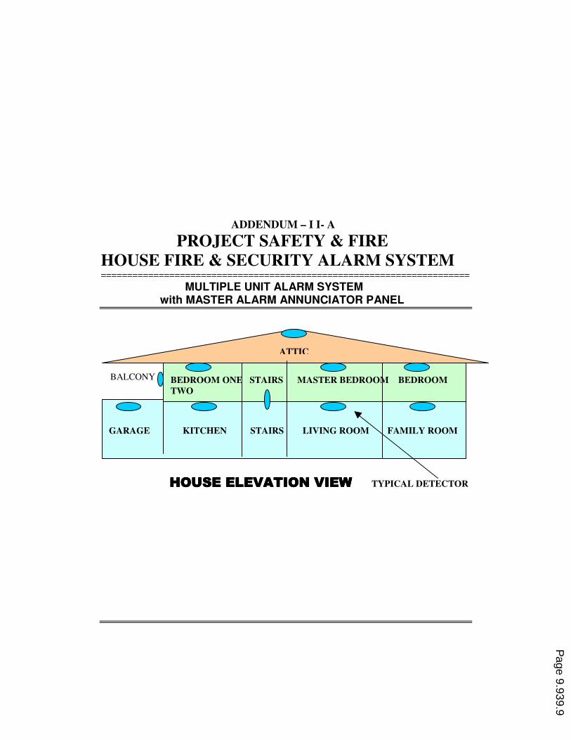
ADDENDUM – I I- A PROJECT SAFETY & FIRE
HOUSE FIRE & SECURITY ALARM SYSTEM ======================================================================
MULTIPLE UNIT ALARM SYSTEM
with MASTER ALARM ANNUNCIATOR PANEL
BALCONY
Typical
Detector
HOUSE ELEVATION VIEW HOUSE ELEVATION VIEW HOUSE ELEVATION VIEW HOUSE ELEVATION VIEW TYPICAL DETECTOR
GARAGE KITCHEN STAIRS LIVING ROOM FAMILY ROOM
BEDROOM ONE STAIRS MASTER BEDROOM BEDROOM
TWO
ATTIC
Page 9.939.9

ADDENDUM – I I- B
PROJECT SAFETY & FIRE
HOUSE FIRE & SECURITY ALARM SYSTEM
Page 9.939.10
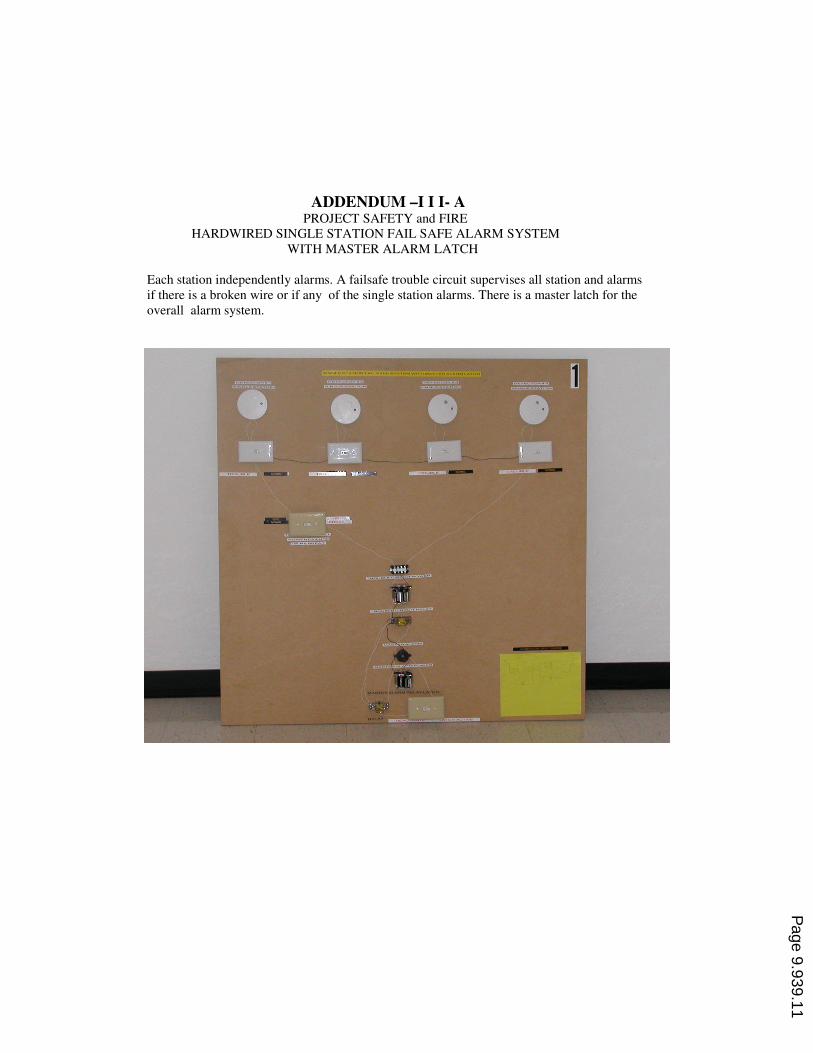
ADDENDUM –I I I- A PROJECT SAFETY and FIRE
HARDWIRED SINGLE STATION FAIL SAFE ALARM SYSTEM
WITH MASTER ALARM LATCH
Each station independently alarms. A failsafe trouble circuit supervises all station and alarms
if there is a broken wire or if any of the single station alarms. There is a master latch for the
overall alarm system.
Page 9.939.11

ADDENDUM – I I I - B PROJECT SAFETY and FIRE
HARDWIRED MULTIPLE STATION ALARM SYSTEM
WITH REMOTE ANNUNCIATOR
If any of the stations alarms, all the others also alarm.
An annunciator indicates which stations have alarmed and which station has alarmed first.
Page 9.939.12

ADDENDUM –I I I- C PROJECT SAFETY and FIRE
PROGRAMMABLE CONTROLLED ALARM SYSTEM
WITH VARIOUS HARDWARE
Various detectors are connected as inputs and various alarms & other devices are connected as
outputs to the programmable control unit. The control logic is programmed into the control unit to
create a variety of alarm systems. An annuciator panel also works in conjunction with the system.
Page 9.939.13

Page 9.939.14