Toggle Switches | NTE Electronics, Inc. · Toggle Switches NTE NTE
NATIONAL
INFOTECH A way to Power
Electronics And
Embedded System
Solutions …
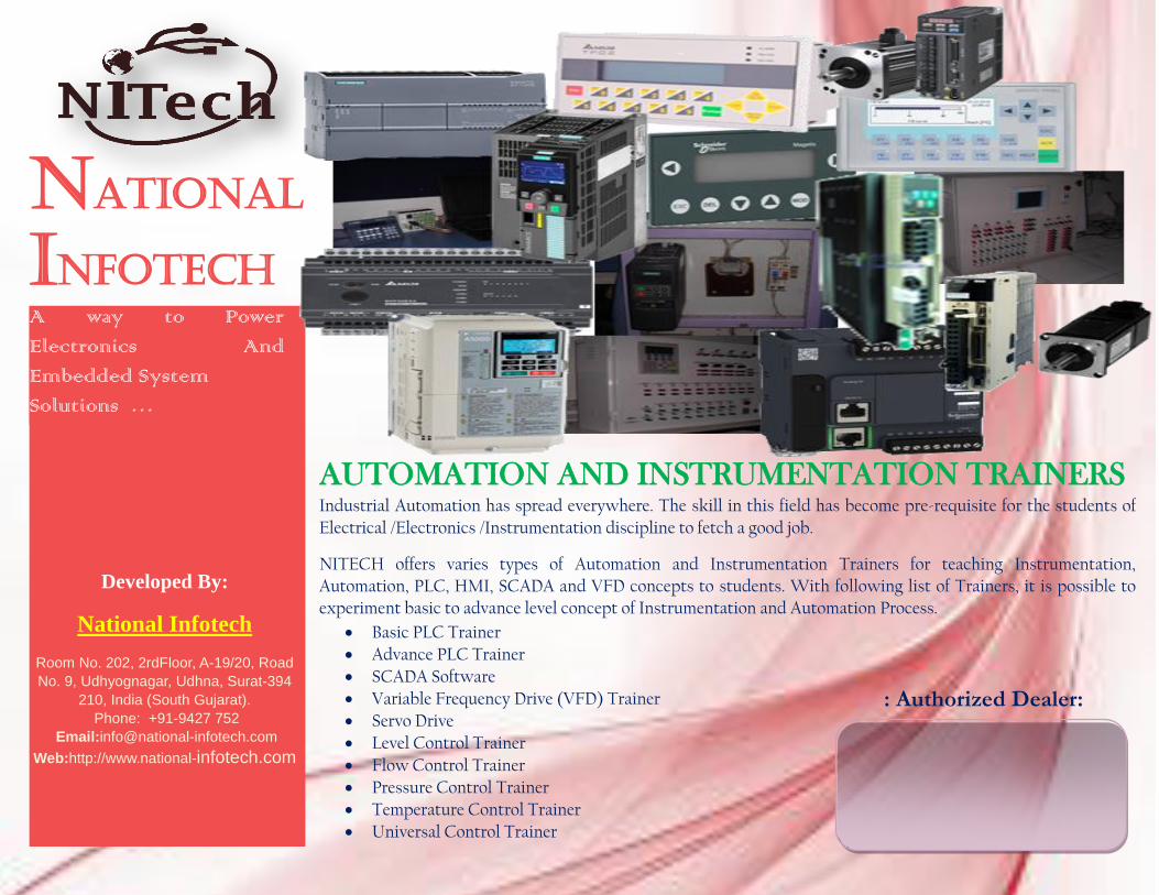
AUTOMATION AND INSTRUMENTATION TRAINERS Industrial Automation has spread everywhere. The skill in this field has become pre-requisite for the students of
Electrical /Electronics /Instrumentation discipline to fetch a good job.
NITECH offers varies types of Automation and Instrumentation Trainers for teaching Instrumentation, Automation, PLC, HMI, SCADA and VFD concepts to students. With following list of Trainers, it is possible to experiment basic to advance level concept of Instrumentation and Automation Process.
Basic PLC Trainer
Advance PLC Trainer
SCADA Software
Variable Frequency Drive (VFD) Trainer
Servo Drive
Level Control Trainer
Flow Control Trainer
Pressure Control Trainer
Temperature Control Trainer
Universal Control Trainer
Developed By:
National Infotech
Room No. 202, 2rdFloor, A-19/20, Road
No. 9, Udhyognagar, Udhna, Surat-394
210, India (South Gujarat).
Phone: +91-9427 752
Email:[email protected]
Web:http://www.national-infotech.com
: Authorized Dealer:
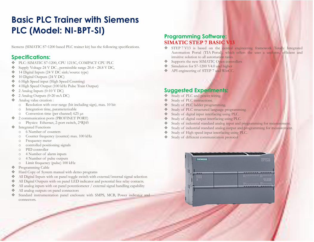
Basic PLC Trainer with Siemens
PLC (Model: NI-BPT-SI)
Siemens (SIMATIC S7‐1200 based PLC trainer kit) has the following specifications.
Specifications: PLC: SIMATIC S7‐1200, CPU 1215C, COMPACT CPU PLC
Supply Voltage 24 V DC , permissible range 20.4 ‐ 28.8 V DC,
14 Digital Inputs (24 V DC sink/source type)
10 Digital Outputs (24 V DC)
6 High Speed input (High Speed Counting)
4 High Speed Output (100 kHz Pulse Train Output)
2 Analog Inputs (0‐10 V DC)
2 Analog Outputs (0‐20 mA DC)
Analog value creation : o Resolution with over range (bit including sign), max. 10 bit o Integration time, parameterizable o Conversion time (per channel) 625 μs
2 communication ports (PROFINET PORT) o Physics: Ethernet, 2-port switch, 2*RJ45
Integrated Functions o 6 Number of counters o Counter frequency (counter) max. 100 kHz o Frequency meter o controlled positioning signals o PID controller o 4 Number of alarm inputs o 4 Number of pulse outputs o Limit frequency (pulse) 100 kHz
Programming Cable
Hard Copy of System manual with demo programs
All Digital Inputs with on panel toggle switch with external/internal signal selection
All Digital Outputs with on panel LED indicator and potential free relay contacts.
All analog inputs with on panel potentiometer / external signal handling capability
All analog outputs on panel connectors
Standard instrumentation panel enclosure with SMPS, MCB, Power indicator and connectors.
Programming Software: SIMATIC STEP 7 BASIC V13 STEP 7 V13 is based on the central engineering framework Totally Integrated
Automation Portal (TIA Portal), which offers the user a uniform, efficient and intuitive solution to all automation tasks.
Supports the new SIMATIC Open controllers
Simulation for S7-1200 V4.0 and higher
API engineering of STEP 7 and WinCC.
Suggested Experiments: Study of PLC and power wiring.
Study of PLC instructions.
Study of PLC ladder programming.
Study of PLC structured language programming.
Study of digital input interfacing using PLC.
Study of digital output interfacing using PLC.
Study of industrial standard analog input and programming for measurement.
Study of industrial standard analog output and programming for measurement.
Study of High speed input interfacing using PLC.
Study of different communication protocol
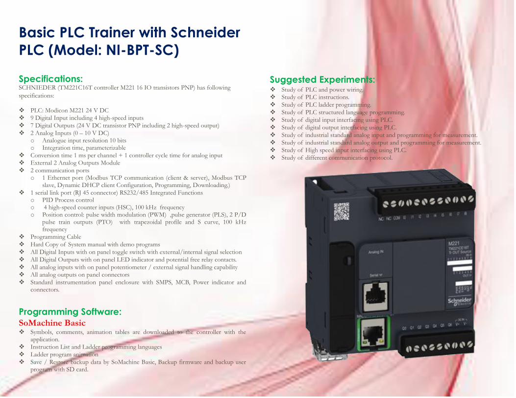
Basic PLC Trainer with Schneider
PLC (Model: NI-BPT-SC)
Specifications: SCHNIEDER (TM221C16T controller M221 16 IO transistors PNP) has following
specifications:
PLC: Modicon M221 24 V DC
9 Digital Input including 4 high-speed inputs
7 Digital Outputs (24 V DC transistor PNP including 2 high-speed output)
2 Analog Inputs (0 – 10 V DC) o Analogue input resolution 10 bits o Integration time, parameterizable
Conversion time 1 ms per channel + 1 controller cycle time for analog input
External 2 Analog Outputs Module
2 communication ports o 1 Ethernet port (Modbus TCP communication (client & server), Modbus TCP
slave, Dynamic DHCP client Configuration, Programming, Downloading.)
1 serial link port (RJ 45 connector) RS232/485 Integrated Functions o PID Process control o 4 high-speed counter inputs (HSC), 100 kHz frequency o Position control: pulse width modulation (PWM) ,pulse generator (PLS), 2 P/D
pulse train outputs (PTO) with trapezoidal profile and S curve, 100 kHz frequency
Programming Cable
Hard Copy of System manual with demo programs
All Digital Inputs with on panel toggle switch with external/internal signal selection
All Digital Outputs with on panel LED indicator and potential free relay contacts.
All analog inputs with on panel potentiometer / external signal handling capability
All analog outputs on panel connectors
Standard instrumentation panel enclosure with SMPS, MCB, Power indicator and connectors.
Programming Software: SoMachine Basic Symbols, comments, animation tables are downloaded to the controller with the
application.
Instruction List and Ladder programming languages
Ladder program animation
Save / Restore backup data by SoMachine Basic, Backup firmware and backup user program with SD card.
Suggested Experiments: Study of PLC and power wiring.
Study of PLC instructions.
Study of PLC ladder programming.
Study of PLC structured language programming.
Study of digital input interfacing using PLC.
Study of digital output interfacing using PLC.
Study of industrial standard analog input and programming for measurement.
Study of industrial standard analog output and programming for measurement.
Study of High speed input interfacing using PLC.
Study of different communication protocol.
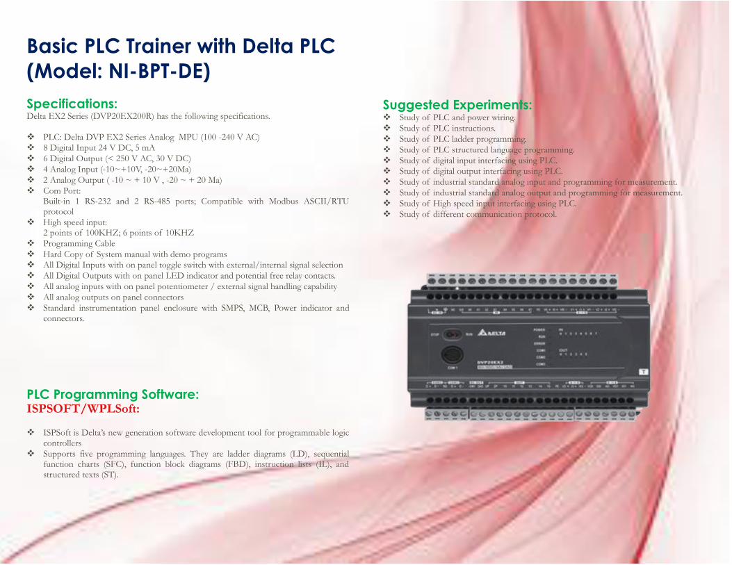
Basic PLC Trainer with Delta PLC
(Model: NI-BPT-DE)
Specifications: Delta EX2 Series (DVP20EX200R) has the following specifications.
PLC: Delta DVP EX2 Series Analog MPU (100 -240 V AC)
8 Digital Input 24 V DC, 5 mA
6 Digital Output (< 250 V AC, 30 V DC)
4 Analog Input (-10~+10V, -20~+20Ma)
2 Analog Output ( -10 ~ + 10 V , -20 ~ + 20 Ma)
Com Port: Built-in 1 RS-232 and 2 RS-485 ports; Compatible with Modbus ASCII/RTU protocol
High speed input: 2 points of 100KHZ; 6 points of 10KHZ
Programming Cable
Hard Copy of System manual with demo programs
All Digital Inputs with on panel toggle switch with external/internal signal selection
All Digital Outputs with on panel LED indicator and potential free relay contacts.
All analog inputs with on panel potentiometer / external signal handling capability
All analog outputs on panel connectors
Standard instrumentation panel enclosure with SMPS, MCB, Power indicator and connectors.
PLC Programming Software: ISPSOFT/WPLSoft:
ISPSoft is Delta’s new generation software development tool for programmable logic controllers
Supports five programming languages. They are ladder diagrams (LD), sequential function charts (SFC), function block diagrams (FBD), instruction lists (IL), and structured texts (ST).
Suggested Experiments: Study of PLC and power wiring.
Study of PLC instructions.
Study of PLC ladder programming.
Study of PLC structured language programming.
Study of digital input interfacing using PLC.
Study of digital output interfacing using PLC.
Study of industrial standard analog input and programming for measurement.
Study of industrial standard analog output and programming for measurement.
Study of High speed input interfacing using PLC.
Study of different communication protocol.
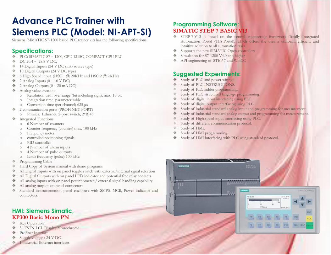
Advance PLC Trainer with
Siemens PLC (Model: NI-APT-SI) Siemens (SIMATIC S7‐1200 based PLC trainer kit) has the following specifications.
Specifications: PLC: SIMATIC S7 ‐ 1200, CPU 1215C, COMPACT CPU PLC
DC 20.4 ‐ 28.8 V DC,
14 Digital Inputs (24 V DC sink/source type)
10 Digital Outputs (24 V DC type)
6 High Speed input. (HSC 1 @ 20KHz and HSC 2 @ 2KHz)
2 Analog Inputs (0 ‐ 10 V DC)
2 Analog Outputs (0 ‐ 20 mA DC)
Analog value creation : o Resolution with over range (bit including sign), max. 10 bit o Integration time, parameterizable o Conversion time (per channel) 625 μs
2 communication ports (PROFINET PORT) o Physics: Ethernet, 2-port switch, 2*RJ45
Integrated Functions o 6 Number of counters o Counter frequency (counter) max. 100 kHz o Frequency meter o controlled positioning signals o PID controller o 4 Number of alarm inputs o 4 Number of pulse outputs o Limit frequency (pulse) 100 kHz
Programming Cable
Hard Copy of System manual with demo programs
All Digital Inputs with on panel toggle switch with external/internal signal selection
All Digital Outputs with on panel LED indicator and potential free relay contacts.
All analog inputs with on panel potentiometer / external signal handling capability
All analog outputs on panel connectors
Standard instrumentation panel enclosure with SMPS, MCB, Power indicator and connectors.
HMI: Siemens Simatic, KP300 Basic Mono PN Key Operation
3” FSTN LCL Display Monochrome
Profinet Interface
Supply voltage : 24 V DC
1 industrial Ethernet interfaces
Programming Software: SIMATIC STEP 7 BASIC V13 STEP 7 V13 is based on the central engineering framework Totally Integrated
Automation Portal (TIA Portal), which offers the user a uniform, efficient and intuitive solution to all automation tasks.
Supports the new SIMATIC Open controllers
Simulation for S7-1200 V4.0 and higher
API engineering of STEP 7 and WinCC
Suggested Experiments:
Study of PLC and power wiring.
Study of PLC INSTRUCTIONS.
Study of PLC ladder programming.
Study of PLC structured language programming.
Study of digital input interfacing using PLC.
Study of digital output interfacing using PLC.
Study of industrial standard analog input and programming for measurement.
Study of industrial standard analog output and programming for measurement.
Study of High speed input interfacing using PLC.
Study of different communication protocol.
Study of HMI.
Study of HMI programming.
Study of HMI interfacing with PLC using standard protocol.
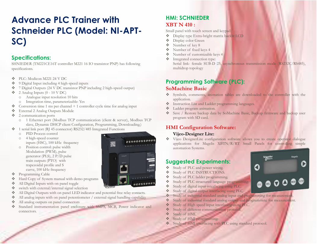
Advance PLC Trainer with
Schneider PLC (Model: NI-APT-
SC)
Specifications: SHNIEDER (TM221CE16T controller M221 16 IO transistor PNP) has following
specifications.
PLC: Modicon M221 24 V DC
9 Digital Input including 4 high-speed inputs
7 Digital Outputs (24 V DC transistor PNP including 2 high-speed output)
2 Analog Inputs (0 - 10 V DC) o Analogue input resolution 10 bits o Integration time, parameterizable: Yes
Conversion time 1 ms per channel + 1 controller cycle time for analog input
External 2 Analog Outputs Module
2 communication ports o 1 Ethernet port (Modbus TCP communication (client & server), Modbus TCP
slave, Dynamic DHCP client Configuration, Programming, Downloading.)
1 serial link port (RJ 45 connector) RS232/485 Integrated Functions o PID Process control o 4 high-speed counter
inputs (HSC), 100 kHz frequency o Position control: pulse width
Modulation (PWM), pulse generator (PLS), 2 P/D pulse train outputs (PTO) with trapezoidal profile and S curve, 100 kHz frequency
Programming Cable
Hard Copy of System manual with demo programs
All Digital Inputs with on panel toggle
switch with external/internal signal selection
All Digital Outputs with on panel LED indicator and potential free relay contacts.
All analog inputs with on panel potentiometer / external signal handling capability
All analog outputs on panel connectors
Standard instrumentation panel enclosure with SMPS, MCB, Power indicator and connectors.
HMI: SCHNIEDER XBT N 410 : Small panel with touch screen and keypad
Display type Extra-bright matrix backlit LCD
Display color Green
Number of key 8
Number of fixed keys 4
Number of customizable keys 4
Integrated connection type: Serial link- female SUB-D 25, asynchronous transmission mode (RS232C/RS485), multidrop topology
Programming Software (PLC): SoMachine Basic Symbols, comments, animation tables are downloaded to the controller with the
application.
Instruction List and Ladder programming languages.
Ladder program animation.
Save / Restore backup data by SoMachine Basic, Backup firmware and backup user program with SD card.
HMI Configuration Software: Vijeo-Designer Lite:
Vijeo DesignerLite configuration software allows you to create operator dialogue applications for Magelis XBTN/R/RT Small Panels for controlling simple automation Systems.
Suggested Experiments: Study of PLC and power wiring.
Study of PLC INSTRUCTIONS.
Study of PLC ladder programming.
Study of PLC structured language programming.
Study of digital input interfacing using PLC.
Study of digital output interfacing using PLC.
Study of industrial standard analog input and programming for measurement.
Study of industrial standard analog output and programming for measurement.
Study of High speed input interfacing using PLC.
Study of different communication protocol.
Study of HMI.
Study of HMI programming.
Study of HMI interfacing with PLC using standard protocol.
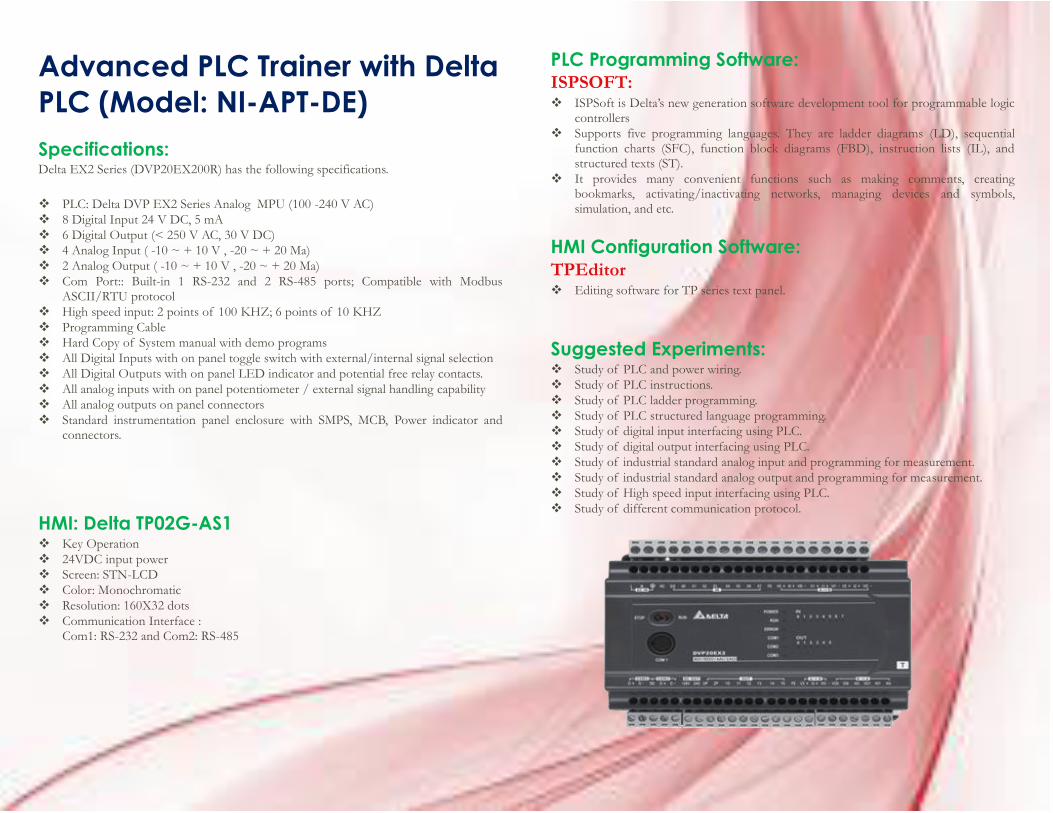
Advanced PLC Trainer with Delta
PLC (Model: NI-APT-DE)
Specifications: Delta EX2 Series (DVP20EX200R) has the following specifications.
PLC: Delta DVP EX2 Series Analog MPU (100 -240 V AC)
8 Digital Input 24 V DC, 5 mA
6 Digital Output (< 250 V AC, 30 V DC)
4 Analog Input ( -10 ~ + 10 V , -20 ~ + 20 Ma)
2 Analog Output ( -10 ~ + 10 V , -20 ~ + 20 Ma)
Com Port:: Built-in 1 RS-232 and 2 RS-485 ports; Compatible with Modbus ASCII/RTU protocol
High speed input: 2 points of 100 KHZ; 6 points of 10 KHZ
Programming Cable
Hard Copy of System manual with demo programs
All Digital Inputs with on panel toggle switch with external/internal signal selection
All Digital Outputs with on panel LED indicator and potential free relay contacts.
All analog inputs with on panel potentiometer / external signal handling capability
All analog outputs on panel connectors
Standard instrumentation panel enclosure with SMPS, MCB, Power indicator and connectors.
HMI: Delta TP02G-AS1 Key Operation
24VDC input power
Screen: STN-LCD
Color: Monochromatic
Resolution: 160X32 dots
Communication Interface : Com1: RS-232 and Com2: RS-485
PLC Programming Software: ISPSOFT: ISPSoft is Delta’s new generation software development tool for programmable logic
controllers
Supports five programming languages. They are ladder diagrams (LD), sequential function charts (SFC), function block diagrams (FBD), instruction lists (IL), and structured texts (ST).
It provides many convenient functions such as making comments, creating bookmarks, activating/inactivating networks, managing devices and symbols, simulation, and etc.
HMI Configuration Software: TPEditor Editing software for TP series text panel.
Suggested Experiments: Study of PLC and power wiring.
Study of PLC instructions.
Study of PLC ladder programming.
Study of PLC structured language programming.
Study of digital input interfacing using PLC.
Study of digital output interfacing using PLC.
Study of industrial standard analog input and programming for measurement.
Study of industrial standard analog output and programming for measurement.
Study of High speed input interfacing using PLC.
Study of different communication protocol.
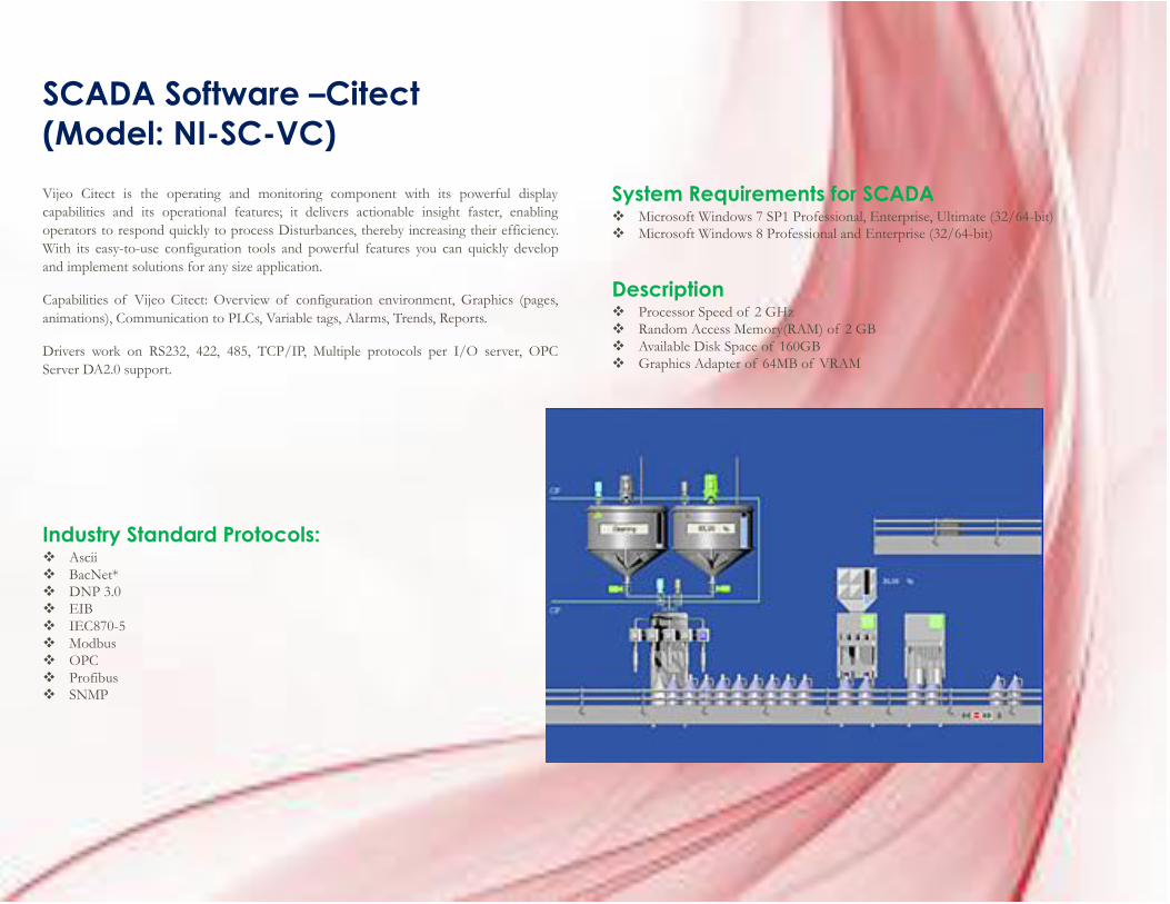
SCADA Software –Citect
(Model: NI-SC-VC)
Vijeo Citect is the operating and monitoring component with its powerful display
capabilities and its operational features; it delivers actionable insight faster, enabling
operators to respond quickly to process Disturbances, thereby increasing their efficiency.
With its easy-to-use configuration tools and powerful features you can quickly develop
and implement solutions for any size application.
Capabilities of Vijeo Citect: Overview of configuration environment, Graphics (pages,
animations), Communication to PLCs, Variable tags, Alarms, Trends, Reports.
Drivers work on RS232, 422, 485, TCP/IP, Multiple protocols per I/O server, OPC
Server DA2.0 support.
Industry Standard Protocols: Ascii
BacNet*
DNP 3.0
EIB
IEC870-5
Modbus
OPC
Profibus
SNMP
System Requirements for SCADA Microsoft Windows 7 SP1 Professional, Enterprise, Ultimate (32/64-bit)
Microsoft Windows 8 Professional and Enterprise (32/64-bit)
Description Processor Speed of 2 GHz
Random Access Memory(RAM) of 2 GB
Available Disk Space of 160GB
Graphics Adapter of 64MB of VRAM
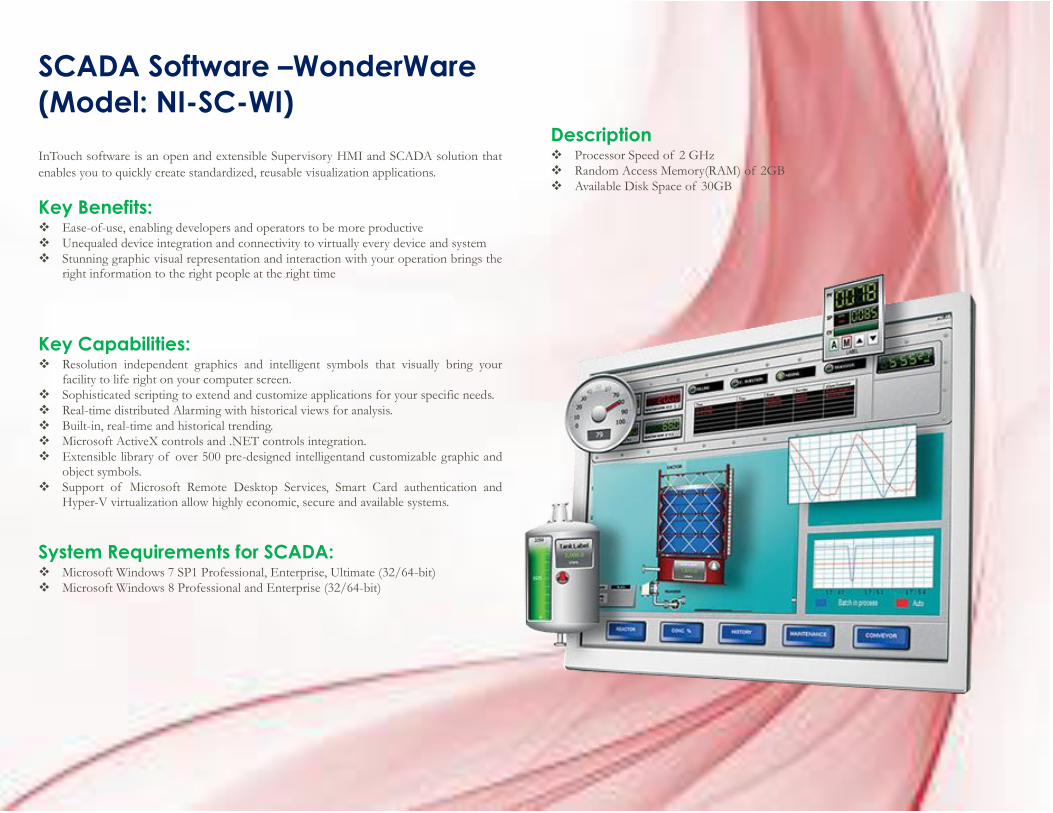
SCADA Software –WonderWare
(Model: NI-SC-WI)
InTouch software is an open and extensible Supervisory HMI and SCADA solution that
enables you to quickly create standardized, reusable visualization applications.
Key Benefits: Ease-of-use, enabling developers and operators to be more productive
Unequaled device integration and connectivity to virtually every device and system
Stunning graphic visual representation and interaction with your operation brings the right information to the right people at the right time
Key Capabilities: Resolution independent graphics and intelligent symbols that visually bring your
facility to life right on your computer screen.
Sophisticated scripting to extend and customize applications for your specific needs.
Real-time distributed Alarming with historical views for analysis.
Built-in, real-time and historical trending.
Microsoft ActiveX controls and .NET controls integration.
Extensible library of over 500 pre-designed intelligentand customizable graphic and object symbols.
Support of Microsoft Remote Desktop Services, Smart Card authentication and Hyper-V virtualization allow highly economic, secure and available systems.
System Requirements for SCADA: Microsoft Windows 7 SP1 Professional, Enterprise, Ultimate (32/64-bit)
Microsoft Windows 8 Professional and Enterprise (32/64-bit)
Description Processor Speed of 2 GHz
Random Access Memory(RAM) of 2GB
Available Disk Space of 30GB
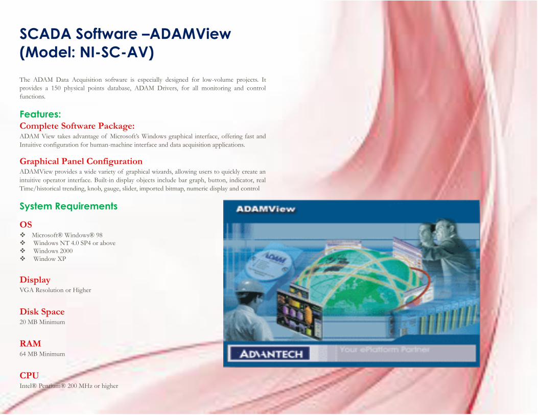
SCADA Software –ADAMView
(Model: NI-SC-AV)
The ADAM Data Acquisition software is especially designed for low-volume projects. It
provides a 150 physical points database, ADAM Drivers, for all monitoring and control
functions.
Features: Complete Software Package: ADAM View takes advantage of Microsoft’s Windows graphical interface, offering fast and
Intuitive configuration for human-machine interface and data acquisition applications.
Graphical Panel Configuration ADAMView provides a wide variety of graphical wizards, allowing users to quickly create an
intuitive operator interface. Built-in display objects include bar graph, button, indicator, real
Time/historical trending, knob, gauge, slider, imported bitmap, numeric display and control
System Requirements
OS Microsoft® Windows® 98
Windows NT 4.0 SP4 or above
Windows 2000
Window XP
Display VGA Resolution or Higher
Disk Space 20 MB Minimum
RAM 64 MB Minimum
CPU Intel® Pentium® 200 MHz or higher
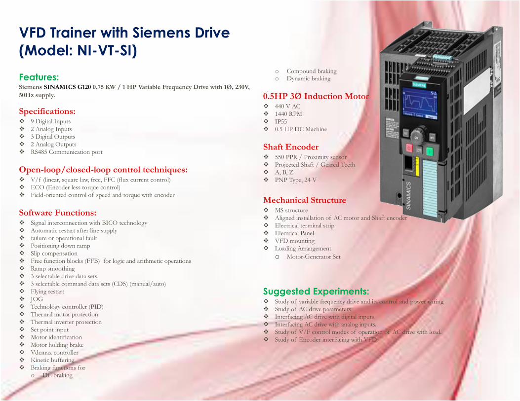
VFD Trainer with Siemens Drive
(Model: NI-VT-SI)
Features: Siemens SINAMICS G120 0.75 KW / 1 HP Variable Frequency Drive with 1Ø, 230V,
50Hz supply.
Specifications: 9 Digital Inputs
2 Analog Inputs
3 Digital Outputs
2 Analog Outputs
RS485 Communication port
Open-loop/closed-loop control techniques: V/f (linear, square law, free, FFC (flux current control)
ECO (Encoder less torque control)
Field-oriented control of speed and torque with encoder
Software Functions: Signal interconnection with BICO technology
Automatic restart after line supply
failure or operational fault
Positioning down ramp
Slip compensation
Free function blocks (FFB) for logic and arithmetic operations
Ramp smoothing
3 selectable drive data sets
3 selectable command data sets (CDS) (manual/auto)
Flying restart
JOG
Technology controller (PID)
Thermal motor protection
Thermal inverter protection
Set point input
Motor identification
Motor holding brake
Vdcmax controller
Kinetic buffering
Braking functions for o DC braking
o Compound braking o Dynamic braking
0.5HP 3Ø Induction Motor 440 V AC
1440 RPM
IP55
0.5 HP DC Machine
Shaft Encoder 550 PPR / Proximity sensor
Projected Shaft / Geared Teeth
A, B, Z
PNP Type, 24 V
Mechanical Structure MS structure
Aligned installation of AC motor and Shaft encoder
Electrical terminal strip
Electrical Panel
VFD mounting
Loading Arrangement
o Motor-Generator Set
Suggested Experiments: Study of variable frequency drive and its control and power wiring.
Study of AC drive parameters
Interfacing AC drive with digital inputs
Interfacing AC drive with analog inputs.
Study of V/F control modes of operation of AC drive with load.
Study of Encoder interfacing with VFD.
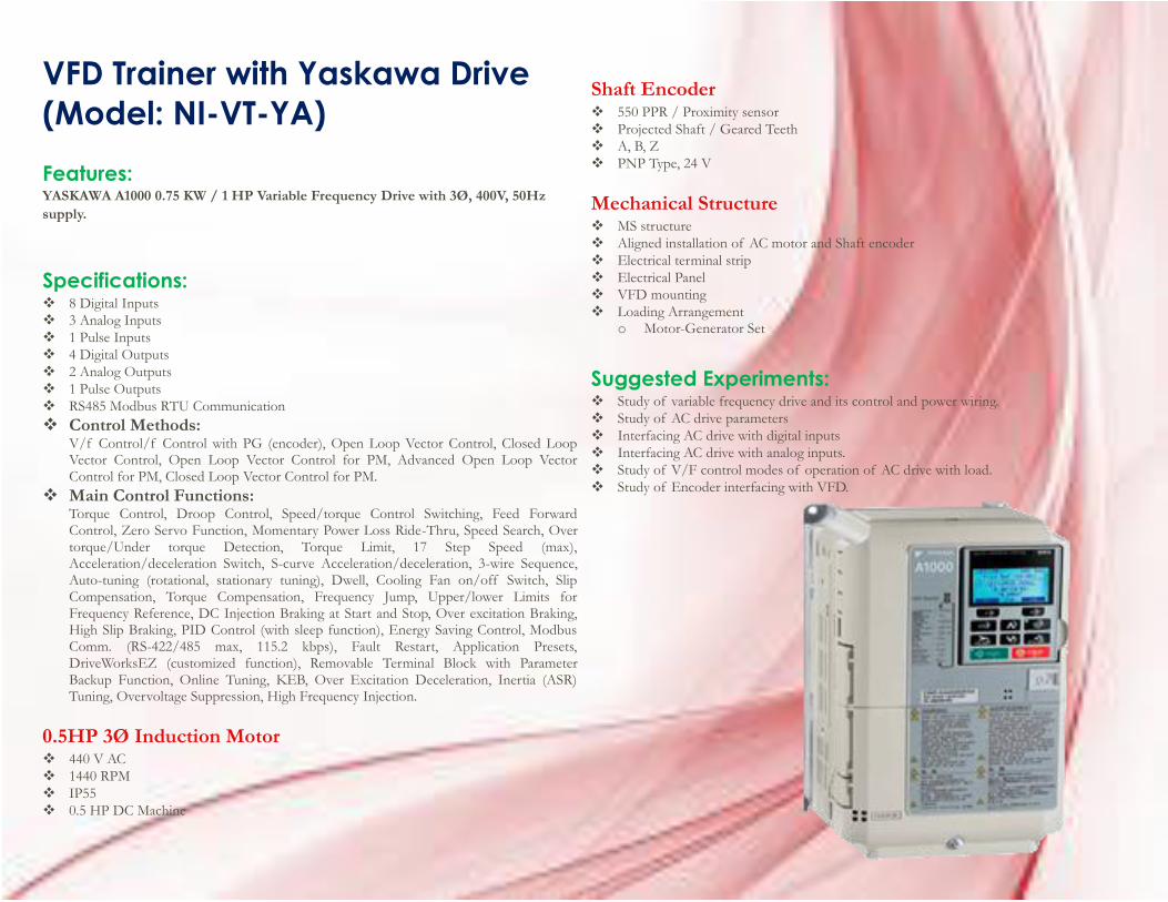
VFD Trainer with Yaskawa Drive
(Model: NI-VT-YA)
Features: YASKAWA A1000 0.75 KW / 1 HP Variable Frequency Drive with 3Ø, 400V, 50Hz
supply.
Specifications: 8 Digital Inputs
3 Analog Inputs
1 Pulse Inputs
4 Digital Outputs
2 Analog Outputs
1 Pulse Outputs
RS485 Modbus RTU Communication
Control Methods: V/f Control/f Control with PG (encoder), Open Loop Vector Control, Closed Loop Vector Control, Open Loop Vector Control for PM, Advanced Open Loop Vector Control for PM, Closed Loop Vector Control for PM.
Main Control Functions: Torque Control, Droop Control, Speed/torque Control Switching, Feed Forward Control, Zero Servo Function, Momentary Power Loss Ride-Thru, Speed Search, Over torque/Under torque Detection, Torque Limit, 17 Step Speed (max), Acceleration/deceleration Switch, S-curve Acceleration/deceleration, 3-wire Sequence, Auto-tuning (rotational, stationary tuning), Dwell, Cooling Fan on/off Switch, Slip Compensation, Torque Compensation, Frequency Jump, Upper/lower Limits for Frequency Reference, DC Injection Braking at Start and Stop, Over excitation Braking, High Slip Braking, PID Control (with sleep function), Energy Saving Control, Modbus Comm. (RS-422/485 max, 115.2 kbps), Fault Restart, Application Presets, DriveWorksEZ (customized function), Removable Terminal Block with Parameter Backup Function, Online Tuning, KEB, Over Excitation Deceleration, Inertia (ASR) Tuning, Overvoltage Suppression, High Frequency Injection.
0.5HP 3Ø Induction Motor 440 V AC
1440 RPM
IP55
0.5 HP DC Machine
Shaft Encoder 550 PPR / Proximity sensor
Projected Shaft / Geared Teeth
A, B, Z
PNP Type, 24 V
Mechanical Structure MS structure
Aligned installation of AC motor and Shaft encoder
Electrical terminal strip
Electrical Panel
VFD mounting
Loading Arrangement o Motor-Generator Set
Suggested Experiments: Study of variable frequency drive and its control and power wiring.
Study of AC drive parameters
Interfacing AC drive with digital inputs
Interfacing AC drive with analog inputs.
Study of V/F control modes of operation of AC drive with load.
Study of Encoder interfacing with VFD.
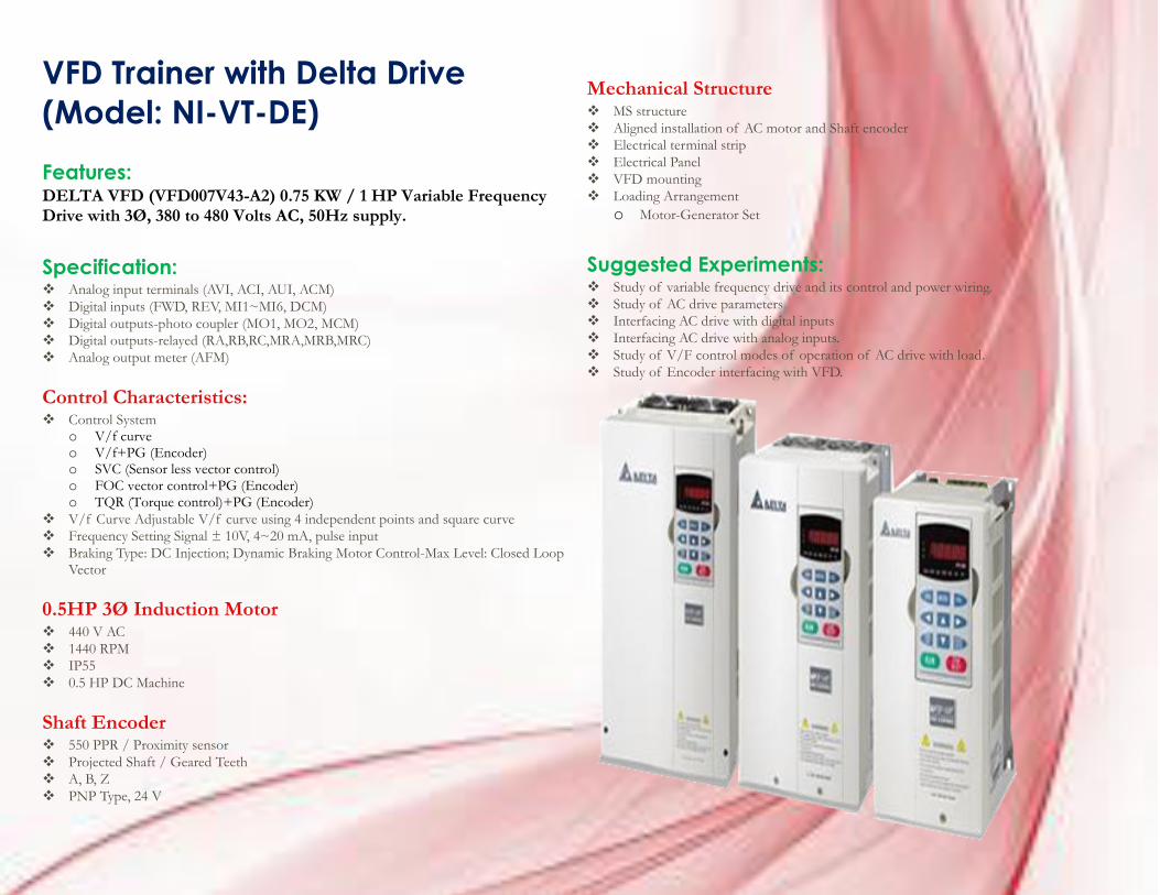
VFD Trainer with Delta Drive
(Model: NI-VT-DE)
Features: DELTA VFD (VFD007V43-A2) 0.75 KW / 1 HP Variable Frequency Drive with 3Ø, 380 to 480 Volts AC, 50Hz supply.
Specification: Analog input terminals (AVI, ACI, AUI, ACM)
Digital inputs (FWD, REV, MI1~MI6, DCM)
Digital outputs-photo coupler (MO1, MO2, MCM)
Digital outputs-relayed (RA,RB,RC,MRA,MRB,MRC)
Analog output meter (AFM)
Control Characteristics: Control System
o V/f curve o V/f+PG (Encoder) o SVC (Sensor less vector control) o FOC vector control+PG (Encoder) o TQR (Torque control)+PG (Encoder)
V/f Curve Adjustable V/f curve using 4 independent points and square curve
Frequency Setting Signal ± 10V, 4~20 mA, pulse input
Braking Type: DC Injection; Dynamic Braking Motor Control-Max Level: Closed Loop Vector
0.5HP 3Ø Induction Motor
440 V AC
1440 RPM
IP55
0.5 HP DC Machine
Shaft Encoder 550 PPR / Proximity sensor
Projected Shaft / Geared Teeth
A, B, Z
PNP Type, 24 V
Mechanical Structure MS structure
Aligned installation of AC motor and Shaft encoder
Electrical terminal strip
Electrical Panel
VFD mounting
Loading Arrangement
o Motor-Generator Set
Suggested Experiments: Study of variable frequency drive and its control and power wiring.
Study of AC drive parameters
Interfacing AC drive with digital inputs
Interfacing AC drive with analog inputs.
Study of V/F control modes of operation of AC drive with load.
Study of Encoder interfacing with VFD.
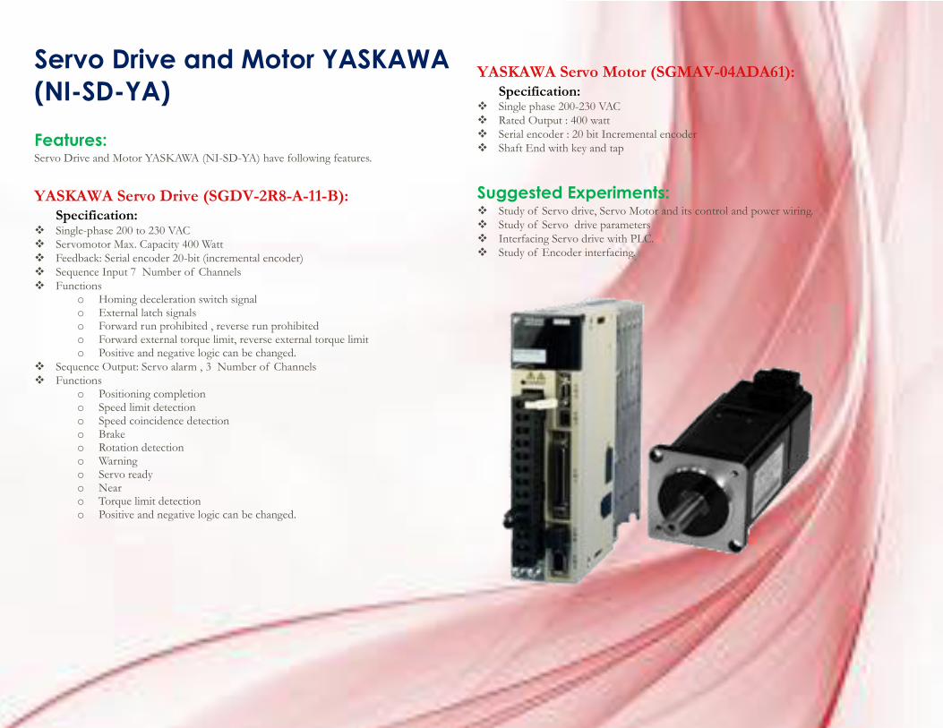
Servo Drive and Motor YASKAWA
(NI-SD-YA)
Features: Servo Drive and Motor YASKAWA (NI-SD-YA) have following features.
YASKAWA Servo Drive (SGDV-2R8-A-11-B): Specification:
Single-phase 200 to 230 VAC
Servomotor Max. Capacity 400 Watt
Feedback: Serial encoder 20-bit (incremental encoder)
Sequence Input 7 Number of Channels
Functions o Homing deceleration switch signal o External latch signals o Forward run prohibited , reverse run prohibited o Forward external torque limit, reverse external torque limit o Positive and negative logic can be changed.
Sequence Output: Servo alarm , 3 Number of Channels
Functions o Positioning completion o Speed limit detection o Speed coincidence detection o Brake o Rotation detection o Warning o Servo ready o Near o Torque limit detection o Positive and negative logic can be changed.
YASKAWA Servo Motor (SGMAV-04ADA61): Specification:
Single phase 200-230 VAC
Rated Output : 400 watt
Serial encoder : 20 bit Incremental encoder
Shaft End with key and tap
Suggested Experiments: Study of Servo drive, Servo Motor and its control and power wiring.
Study of Servo drive parameters
Interfacing Servo drive with PLC.
Study of Encoder interfacing.
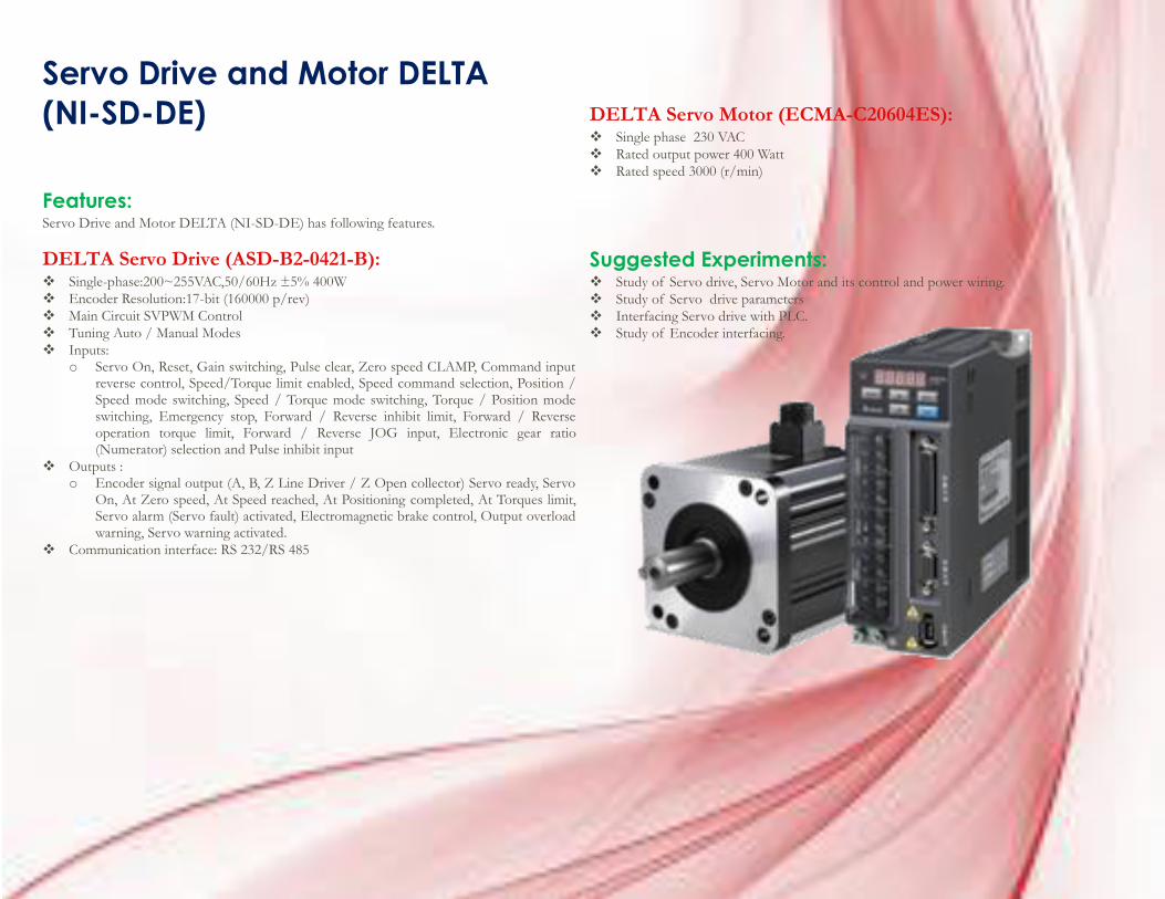
Servo Drive and Motor DELTA
(NI-SD-DE)
Features: Servo Drive and Motor DELTA (NI-SD-DE) has following features.
DELTA Servo Drive (ASD-B2-0421-B): Single-phase:200~255VAC,50/60Hz ±5% 400W
Encoder Resolution:17-bit (160000 p/rev)
Main Circuit SVPWM Control
Tuning Auto / Manual Modes
Inputs: o Servo On, Reset, Gain switching, Pulse clear, Zero speed CLAMP, Command input
reverse control, Speed/Torque limit enabled, Speed command selection, Position / Speed mode switching, Speed / Torque mode switching, Torque / Position mode switching, Emergency stop, Forward / Reverse inhibit limit, Forward / Reverse operation torque limit, Forward / Reverse JOG input, Electronic gear ratio (Numerator) selection and Pulse inhibit input
Outputs : o Encoder signal output (A, B, Z Line Driver / Z Open collector) Servo ready, Servo
On, At Zero speed, At Speed reached, At Positioning completed, At Torques limit, Servo alarm (Servo fault) activated, Electromagnetic brake control, Output overload warning, Servo warning activated.
Communication interface: RS 232/RS 485
DELTA Servo Motor (ECMA-C20604ES): Single phase 230 VAC
Rated output power 400 Watt
Rated speed 3000 (r/min)
Suggested Experiments: Study of Servo drive, Servo Motor and its control and power wiring.
Study of Servo drive parameters
Interfacing Servo drive with PLC.
Study of Encoder interfacing.
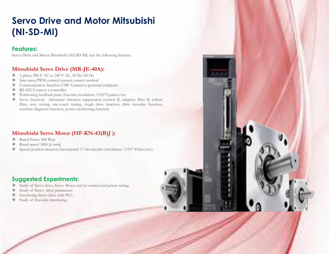
Servo Drive and Motor Mitsubishi
(NI-SD-MI)
Features: Servo Drive and Motor Mitsubishi (NI-SD-MI) has the following features.
Mitsubishi Servo Drive (MR-JE-40A): 1-phase 200 V AC to 240 V AC, 50 Hz/60 Hz
Sine-wave PWM control/current control method
Communication function USB: Connect a personal computer
RS-422: Connect a controller
Positioning feedback pulse Encoder resolution: 131072 pulses/rev
Servo function: Advanced vibration suppression control II, adaptive filter II, robust filter, auto tuning, one-touch tuning, tough drive function, drive recorder function, machine diagnosis function, power monitoring function
Mitsubishi Servo Motor (HF-KN-43(B)J ): Rated Power 400 Watt
Rated speed 3000 [r/min]
Speed/position detector Incremental 17-bit encoder (resolution: 13107 Pulses/rev)
Suggested Experiments: Study of Servo drive, Servo Motor and its control and power wiring.
Study of Servo drive parameters
Interfacing Servo drive with PLC.
Study of Encoder interfacing.
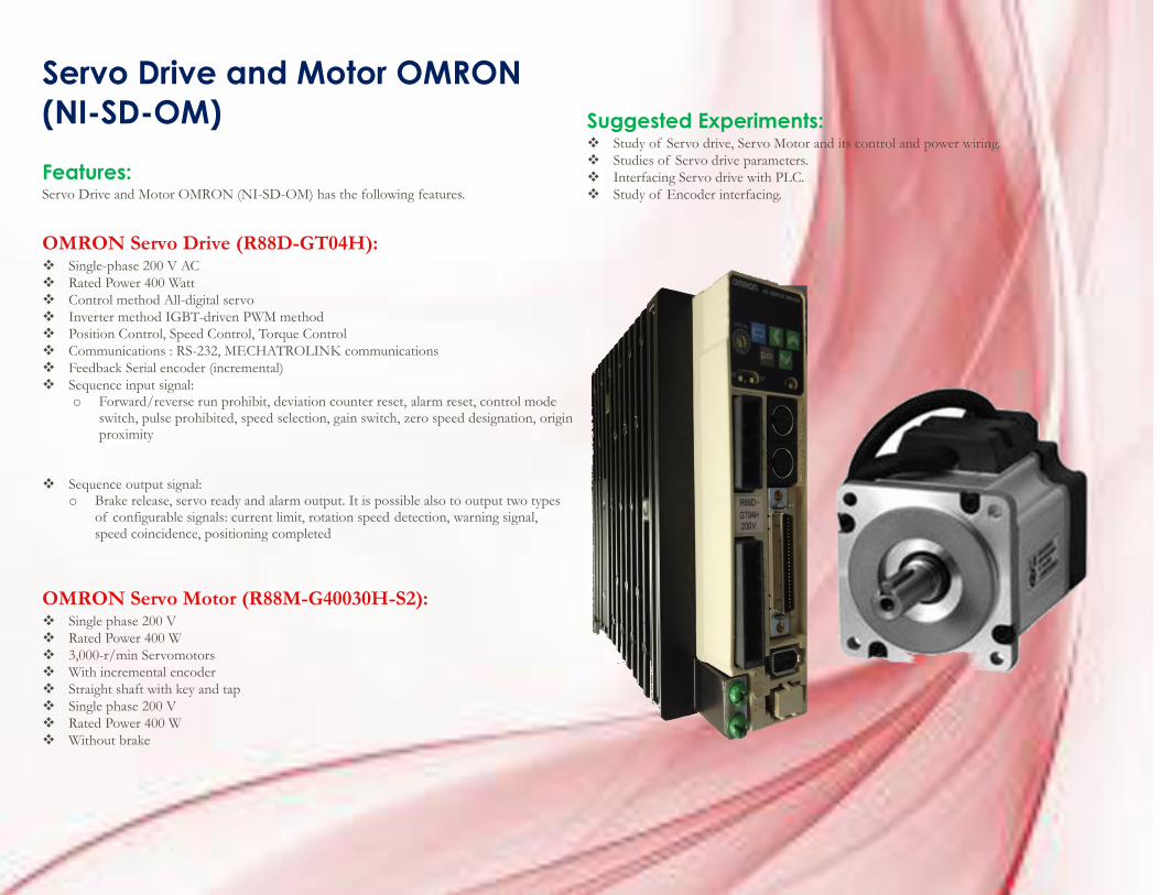
Servo Drive and Motor OMRON
(NI-SD-OM)
Features: Servo Drive and Motor OMRON (NI-SD-OM) has the following features.
OMRON Servo Drive (R88D-GT04H): Single-phase 200 V AC
Rated Power 400 Watt
Control method All-digital servo
Inverter method IGBT-driven PWM method
Position Control, Speed Control, Torque Control
Communications : RS-232, MECHATROLINK communications
Feedback Serial encoder (incremental)
Sequence input signal: o Forward/reverse run prohibit, deviation counter reset, alarm reset, control mode
switch, pulse prohibited, speed selection, gain switch, zero speed designation, origin proximity
Sequence output signal: o Brake release, servo ready and alarm output. It is possible also to output two types
of configurable signals: current limit, rotation speed detection, warning signal, speed coincidence, positioning completed
OMRON Servo Motor (R88M-G40030H-S2): Single phase 200 V
Rated Power 400 W
3,000-r/min Servomotors
With incremental encoder
Straight shaft with key and tap
Single phase 200 V
Rated Power 400 W
Without brake
Suggested Experiments: Study of Servo drive, Servo Motor and its control and power wiring.
Studies of Servo drive parameters.
Interfacing Servo drive with PLC.
Study of Encoder interfacing.
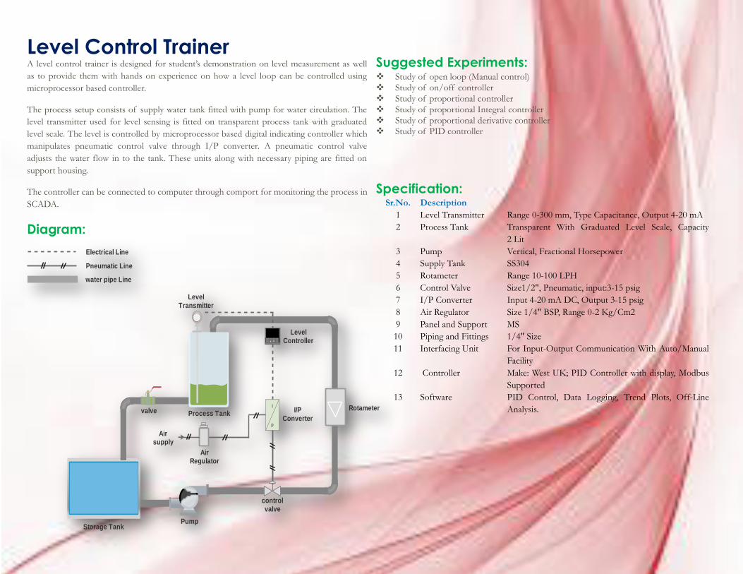
Level Control Trainer A level control trainer is designed for student’s demonstration on level measurement as well
as to provide them with hands on experience on how a level loop can be controlled using
microprocessor based controller.
The process setup consists of supply water tank fitted with pump for water circulation. The
level transmitter used for level sensing is fitted on transparent process tank with graduated
level scale. The level is controlled by microprocessor based digital indicating controller which
manipulates pneumatic control valve through I/P converter. A pneumatic control valve
adjusts the water flow in to the tank. These units along with necessary piping are fitted on
support housing.
The controller can be connected to computer through comport for monitoring the process in
SCADA.
Diagram:
Suggested Experiments: Study of open loop (Manual control)
Study of on/off controller
Study of proportional controller
Study of proportional Integral controller
Study of proportional derivative controller
Study of PID controller
Specification: Sr.No. Description
1 Level Transmitter Range 0-300 mm, Type Capacitance, Output 4-20 mA
2 Process Tank Transparent With Graduated Level Scale, Capacity
2 Lit
3 Pump Vertical, Fractional Horsepower
4 Supply Tank SS304
5 Rotameter Range 10-100 LPH
6 Control Valve Size1/2", Pneumatic, input:3-15 psig
7 I/P Converter Input 4-20 mA DC, Output 3-15 psig
8 Air Regulator Size 1/4" BSP, Range 0-2 Kg/Cm2
9 Panel and Support MS
10 Piping and Fittings 1/4" Size
11 Interfacing Unit For Input-Output Communication With Auto/Manual
Facility
12 Controller Make: West UK; PID Controller with display, Modbus
Supported
13 Software PID Control, Data Logging, Trend Plots, Off-Line
Analysis. I
p
Storage TankPump
control valve
Rotametervalve
Level Transmitter
Level Controller
I/P Converter
Process Tank
Electrical Line
Pneumatic Line
water pipe Line
Air Regulator
Air supply
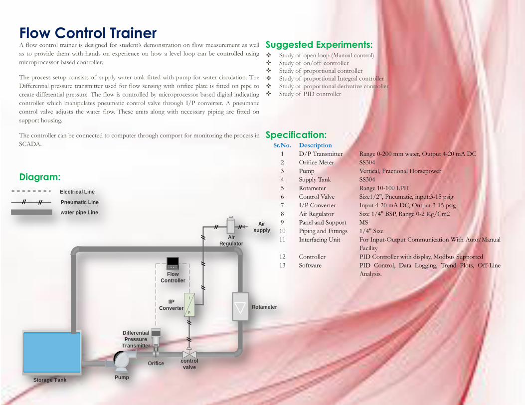
Flow Control Trainer A flow control trainer is designed for student’s demonstration on flow measurement as well
as to provide them with hands on experience on how a level loop can be controlled using
microprocessor based controller.
The process setup consists of supply water tank fitted with pump for water circulation. The
Differential pressure transmitter used for flow sensing with orifice plate is fitted on pipe to
create differential pressure. The flow is controlled by microprocessor based digital indicating
controller which manipulates pneumatic control valve through I/P converter. A pneumatic
control valve adjusts the water flow. These units along with necessary piping are fitted on
support housing.
The controller can be connected to computer through comport for monitoring the process in
SCADA.
Diagram:
Suggested Experiments: Study of open loop (Manual control)
Study of on/off controller
Study of proportional controller
Study of proportional Integral controller
Study of proportional derivative controller
Study of PID controller
Specification: Sr.No. Description
1 D/P Transmitter Range 0-200 mm water, Output 4-20 mA DC
2 Orifice Meter SS304
3 Pump Vertical, Fractional Horsepower
4 Supply Tank SS304
5 Rotameter Range 10-100 LPH
6 Control Valve Size1/2", Pneumatic, input:3-15 psig
7 I/P Converter Input 4-20 mA DC, Output 3-15 psig
8 Air Regulator Size 1/4" BSP, Range 0-2 Kg/Cm2
9 Panel and Support MS
10 Piping and Fittings 1/4" Size
11 Interfacing Unit For Input-Output Communication With Auto/Manual
Facility
12 Controller PID Controller with display, Modbus Supported
13 Software PID Control, Data Logging, Trend Plots, Off-Line
Analysis.
I
p
Storage TankPump
control valve
Rotameter
Orifice
Flow Controller
I/P Converter
Differential Pressure
Transmitter
Electrical Line
Pneumatic Line
water pipe Line
Air Regulator
Air supply
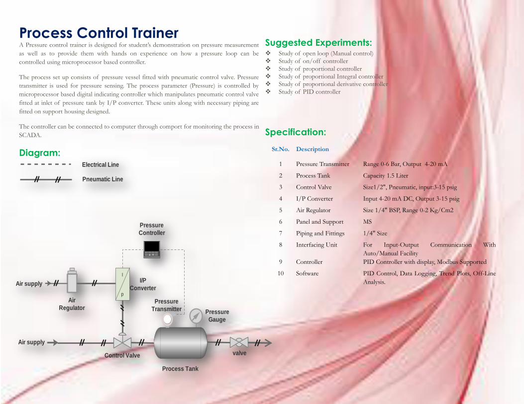
Process Control Trainer A Pressure control trainer is designed for student’s demonstration on pressure measurement
as well as to provide them with hands on experience on how a pressure loop can be
controlled using microprocessor based controller.
The process set up consists of pressure vessel fitted with pneumatic control valve. Pressure
transmitter is used for pressure sensing. The process parameter (Pressure) is controlled by
microprocessor based digital indicating controller which manipulates pneumatic control valve
fitted at inlet of pressure tank by I/P converter. These units along with necessary piping are
fitted on support housing designed.
The controller can be connected to computer through comport for monitoring the process in
SCADA.
Diagram:
Suggested Experiments: Study of open loop (Manual control)
Study of on/off controller
Study of proportional controller
Study of proportional Integral controller
Study of proportional derivative controller
Study of PID controller
Specification:
Sr.No. Description
1 Pressure Transmitter Range 0-6 Bar, Output 4-20 mA
2 Process Tank Capacity 1.5 Liter
3 Control Valve Size1/2", Pneumatic, input:3-15 psig
4 I/P Converter Input 4-20 mA DC, Output 3-15 psig
5 Air Regulator Size 1/4" BSP, Range 0-2 Kg/Cm2
6 Panel and Support MS
7 Piping and Fittings 1/4" Size
8 Interfacing Unit For Input-Output Communication With
Auto/Manual Facility
9 Controller PID Controller with display, Modbus Supported
10 Software PID Control, Data Logging, Trend Plots, Off-Line
Analysis.
I
p
Process Tank
Control Valve valve
Pressure
Controller
I/P
Converter
Pressure
Transmitter
Electrical Line
Pneumatic Line
Air
Regulator
Air supply
Air supply
Pressure
Gauge
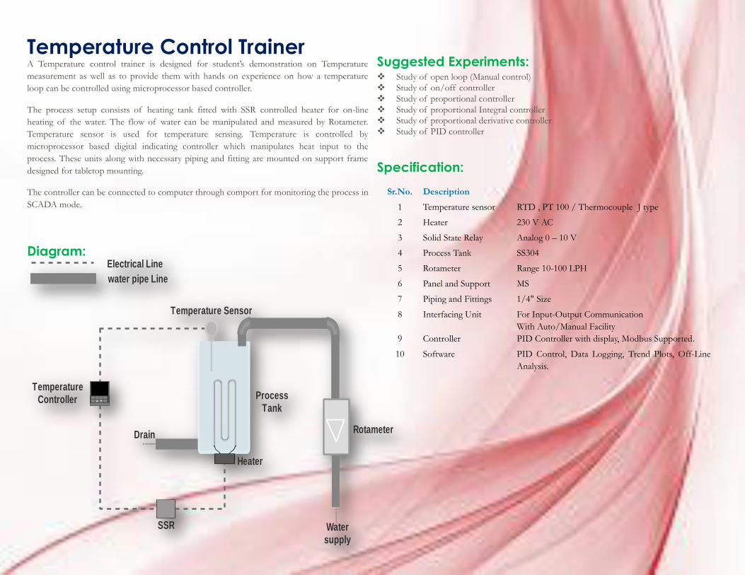
Temperature Control Trainer A Temperature control trainer is designed for student’s demonstration on Temperature
measurement as well as to provide them with hands on experience on how a temperature
loop can be controlled using microprocessor based controller.
The process setup consists of heating tank fitted with SSR controlled heater for on-line
heating of the water. The flow of water can be manipulated and measured by Rotameter.
Temperature sensor is used for temperature sensing. Temperature is controlled by
microprocessor based digital indicating controller which manipulates heat input to the
process. These units along with necessary piping and fitting are mounted on support frame
designed for tabletop mounting.
The controller can be connected to computer through comport for monitoring the process in
SCADA mode.
Diagram:
Suggested Experiments: Study of open loop (Manual control)
Study of on/off controller
Study of proportional controller
Study of proportional Integral controller
Study of proportional derivative controller
Study of PID controller
Specification:
Sr.No. Description
1 Temperature sensor RTD , PT 100 / Thermocouple J type
2 Heater 230 V AC
3 Solid State Relay Analog 0 – 10 V
4 Process Tank SS304
5 Rotameter Range 10-100 LPH
6 Panel and Support MS
7 Piping and Fittings 1/4" Size
8 Interfacing Unit For Input-Output Communication
With Auto/Manual Facility
9 Controller PID Controller with display, Modbus Supported.
10 Software PID Control, Data Logging, Trend Plots, Off-Line
Analysis.
RotameterDrain
Temperature Sensor
Temperature Controller Process
Tank
Electrical Line
water pipe Line
Heater
Water supply
SSR
![DPU2000/1500R/2000R MODBUS / MODBUS PLUS … · DPU2000/1500R/2000R Modbus/Modbus Plus Automation Guide i DPU2000/1500R/2000R MODBUS / MODBUS PLUS ... [Catalog 587XXX00-XXX0 or 587XXXX6-XXX4]](https://static.fdocuments.in/doc/165x107/5acb9eac7f8b9a73128bdc42/dpu20001500r2000r-modbus-modbus-plus-modbusmodbus-plus-automation-guide.jpg)