MURDER ON THE HIGH SPEED RAIL HIGH SPEED RAIL TO ORLANDO, FL.
MAHSR-C6-ADDENDUM NO. 10 Page 1 of 32
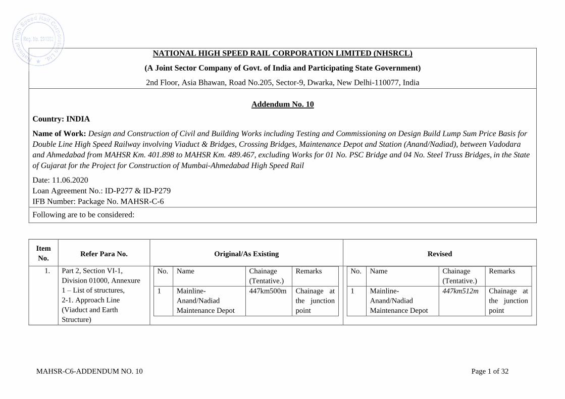
NATIONAL HIGH SPEED RAIL CORPORATION LIMITED (NHSRCL)
(A Joint Sector Company of Govt. of India and Participating State Government)
2nd Floor, Asia Bhawan, Road No.205, Sector-9, Dwarka, New Delhi-110077, India
Addendum No. 10
Country: INDIA
Name of Work: Design and Construction of Civil and Building Works including Testing and Commissioning on Design Build Lump Sum Price Basis for
Double Line High Speed Railway involving Viaduct & Bridges, Crossing Bridges, Maintenance Depot and Station (Anand/Nadiad), between Vadodara
and Ahmedabad from MAHSR Km. 401.898 to MAHSR Km. 489.467, excluding Works for 01 No. PSC Bridge and 04 No. Steel Truss Bridges, in the State
of Gujarat for the Project for Construction of Mumbai-Ahmedabad High Speed Rail
Date: 11.06.2020
Loan Agreement No.: ID-P277 & ID-P279
IFB Number: Package No. MAHSR-C-6
Following are to be considered:
Item
No. Refer Para No. Original/As Existing Revised
1. Part 2, Section VI-1,
Division 01000, Annexure
1 – List of structures,
2-1. Approach Line
(Viaduct and Earth
Structure)
No. Name Chainage
(Tentative.)
Remarks
1 Mainline-
Anand/Nadiad
Maintenance Depot
447km500m Chainage at
the junction
point
No. Name Chainage
(Tentative.)
Remarks
1 Mainline-
Anand/Nadiad
Maintenance Depot
447km512m Chainage at
the junction
point
MAHSR-C6-ADDENDUM NO. 10 Page 2 of 32
Item
No. Refer Para No. Original/As Existing Revised
2. Part 2, Section VI-1,
Division 03000, Sub-
Division 03010, Clause 1,
Definitions, Page 6 of 30.
“HSR Benchmarks” means the benchmarks provided by the
Employer, used to locate, confirm the Right of Way (ROW) &
its co-ordinates including levels.
“Benchmarks” means the benchmarks provided by the
Employer used to locate and confirm the Right of Way (ROW)
and its co-ordinates including levels.
3. Part 2, Section VI-1,
Division 06000, Sub-
Division 06020, Sub-Clause
6.3, Page 16 of 51
The proposed Rail Track Formation Level shall also be also
marked on stakes to indicate embankment height or
excavation depth.
The proposed Rail Level shall also be marked on stakes to
indicate embankment height or excavation depth.
4. Addendum 2, Item 24,
Part 2, Section VI-1,
Sub-Division 06060,
Sub-Clause 2.2.1, item (ii),
Paragraph 1,
Page 36 of 51.
These are various utilities which existed on ground at the time
of acquiring the land by the Employer and may affect the
execution of the work. The Employer takes the responsibility
to dismantle these utilities up to ground level and hand over
the land to the Contractor free of these encumbrances.
Removal of remaining portion below ground level, wherever
required, shall be responsibility of the Contractor. The
Contract Price shall be deemed to include all such works and
risks.
These are various utilities which existed on ground at the time
of acquiring the land by the Employer and may affect the
execution of the work. The Employer takes the responsibility
to dismantle these utilities up to ground level and hand over
the land to the Contractor free of these encumbrances.
Removal of remaining portion below ground level, wherever
required, shall be responsibility of the Contractor. The
Accepted Contract Amount shall be deemed to include all such
works and risks.
5. Part 2, Section VI-2,
Division 02000, Sub-
Division 02020,
Sub-Clause 1.2,
Item b),
Page 08 of 45
b) JGS – Geological Society of Japan
iii. JGS 1816-2002: Method for Rapid Load Test of Single
Piles;
b) JGS – Geological Society of Japan
iii. JGS 1816-2002: Method for Rapid Load Test of Single
Piles; and
iv. JGS 1812-2002: Method for Static Pile-Toe Load Test
of Single Piles
6. Part 2, Section VI-2,
Division 02000, Sub-
Division 02020,
Sub-Clause 1.5.3,
Item (2) iv.,
Page 11 of 45
iv. Pile Load Test: Pile load tests shall be carried as per the
Employer’s Requirements - Technical Specifications. In
addition to initial pile load tests, 1% of the working pile shall
be tested. The Contractor may plan to combine the static and
dynamic/rapid loading tests, if approved by the Engineer.
However, static loading tests shall be carried out on a minimum
iv. Pile Load Test: Pile load tests shall be carried as per the
Employer’s Requirements - Technical Specifications. In
addition to initial pile load tests, 1% of the working piles shall
be tested. The Contractor may plan to combine the static and
dynamic/rapid loading tests, if approved by the Engineer.
However, static loading tests shall be carried out on a minimum

MAHSR-C6-ADDENDUM NO. 10 Page 3 of 32
Item
No. Refer Para No. Original/As Existing Revised
of 25% of the working piles to be tested. Pile load tests shall be
carried as per JGS 1811-2002, JGS 1816-2002; and
of 25% of the working piles to be tested. Pile load tests shall be
carried as per JGS 1811-2002, JGS 1816-2002, unless
otherwise specified in the Employer’s Requirements - Technical
Specifications; and
7. Part 2, Section VI-2,
Division 02000, Sub-
Division 02030, Sub-
Clause 1.1, Page 13 of 45
In principle, the requirements specified in Clause 2 hereof are the common requirements for general viaduct for mainline. For bridge crossings, station rigid frame viaducts, station approach viaducts, ramps, confirmation car base, sub-maintenance depots and feeder structures, other clauses shall be referred to respectively for their particular requirements.
In principle, the requirements specified in Clause 2 are the common requirements. For bridge crossings, station rigid frame viaducts, station approach viaducts, ramps, sub-maintenance depots and feeder structures, other clauses shall be referred to respectively for their particular requirements.
8. Part 2, Section VI-2,
Division 02000, Sub-
Division 02030,
Sub-Clause 2.4.1,
2nd Paragraph,
Page 21 of 45
The bearing stratum shall be either rock or soil. If the bearing
stratum layer is soil, then the foundation embedment depth shall
be more than 0.5m in the bearing stratum layer. In case of rock,
the foundation shall be 0.6m in hard rock or 1.5m in weathered
rock, which shall be confirmed by the Engineer on site in
reference to IRC-78 705.2.2.
The bearing layer shall be either rock or soil. If the bearing
stratum layer is soil, then the foundation embedment depth shall
be more than 0.5m in the bearing stratum layer. In case of rock,
the foundation shall be 0.6m in rock with Unconfined
Compressive Strength (UCS) 12.5MPa or greater, or 1.5m in
rock with UCS 2.5MPa or greater.
9. Part 2, Section VI-2,
Division 02000, Sub-
Division 02030,
Sub-Clause 2.5.1.2,
2nd Paragraph,
Page 22 of 45
If the cast-in-situ pile foundation is planned, pile load tests
(initial and working pile load tests) shall be conducted. The
results of the geotechnical pile design shall be verified by pile
loading tests (refer to the Employer’s Requirements - Technical
Specifications). A test plan shall be submitted to the Engineer
for approval. The test results shall be submitted to the Engineer
immediately after the completion of the test. If the driven pile
foundation is planned, pile driving tests shall be conducted. The
Contractor shall decide the driven pile length according to the
test results and Standard Design drawings and submit the
If the cast-in-situ pile foundation is planned, the Contractor
shall confirm the applicable pile foundation type, the locations
and length of piles at site by carrying out test boring as per
Technical Specifications Division 02000 prior to the
commencement of piling for the Engineer’s consent and
thereafter conduct pile load tests (initial and working pile load
tests). The results of geotechnical pile design shall be verified
by pile loading tests (refer to the Employer’s Requirements -
Technical Specifications). A test plan shall be submitted to the
Engineer for approval. The test results shall be submitted to the

MAHSR-C6-ADDENDUM NO. 10 Page 4 of 32
Item
No. Refer Para No. Original/As Existing Revised
method statements including the criteria for the stopping of
driving to the Engineer for approval.
Engineer immediately after the completion of the test. If the
driven pile foundation is planned, pile driving tests shall be
conducted. The Contractor shall decide the driven pile length
according to the test results and Standard Design drawings and
submit the method statements including the criteria for the
stopping of driving to the Engineer for approval.
10. Part 2, Section VI-2,
Division 02000, Sub-
Division 02030, Sub-
Clause 3.4, Item 2), Page
27 of 45
2. The Standard Design for foundation and sub structure shall
be selected from the Standard Design provided for Viaduct and
Bridges if it is a standing waterbody. For the bridges in flowing
water stream like river, canal etc., other than covered in Para 4
below, Standard Design for foundation and substructure shall
be selected from any of the River Crossing Bridges (based on
similar conditions) covered in Para 4 below. In case a
particular situation is not covered in the Standard Design of
River Crossing Bridges, the suitable available Standard Design
of River Crossing Bridges shall be adopted with the approval
of the Engineer.
2. The Standard Design for foundation and sub structure shall
be selected from the Standard Design provided for Viaduct and
Bridges if it is a standing waterbody. For the bridges in flowing
water stream like river, canal etc., other than covered in Para 4
below, Standard Design for foundation and substructure shall
be selected from any of the Standard Design drawings for
River Crossing Bridges as per DFM. In case a particular
situation is not covered in the Standard Design of River
Crossing Bridges, the suitable available Standard Design of
River Crossing Bridges shall be adopted with the approval of
the Engineer.
11. Part 2, Section VI-2,
Division 02000,
Attachment 5, Sub-
Division 02020, Figure
2.1.11 (Flowchart), Page
85 of 165
Modification of pile length shall be
as per Figure 2.1.13, if required
Modification of pile length shall be
as per Figure 2.1.12, if required
12. Addendum No. 03, Item
No. 61, Attachment No. 09,
Page 18 of 50, Part 2, Sub-
Division 02020, Sub-Clause
(1) Ground Case ①: Scour level up to 5m from the bottom
of the pile cap and N-Value* ≥ 50 below scour level.
(1) Ground Case ①: Scour level up to 5m from the bottom
of the pile cap and N-Value* ≥ 50 below scour level.

MAHSR-C6-ADDENDUM NO. 10 Page 5 of 32
Item
No. Refer Para No. Original/As Existing Revised
2.2.1.3, Item 5), Page 94 of
165 (2) Ground Case ②: Scour level greater than 5m but less
than 10m from the bottom of the pile cap and N-Value* ≥ 50
below scour level.
(3) Ground Case ③: Scour level greater than 10m but less
than 15m from the bottom of the pile cap and N-Value* ≥ 50
below scour level
(4) Ground Case ④: Scour level greater than 15m but less
than 20m from the bottom of the pile cap and N-Value* ≥ 50
below scour level
(5) Ground Case ⑤: Scour level greater than 20m but less than
25m from the bottom of the pile cap and N-Value* ≥ 50 below
scour level
(2) Ground Case ②: Scour level greater than 5m but less
than equal to 10m from the bottom of the pile cap and N-Value*
≥ 50 below scour level.
(3) Ground Case ③: Scour level greater than 10m but less
than equal to 15m from the bottom of the pile cap and N-Value*
≥ 50 below scour level
(4) Ground Case ④: Scour level greater than 15m but less
than equal to 20m from the bottom of the pile cap and N-Value*
≥ 50 below scour level
(5) <Deleted>
13. Part 2, Section VI-2,
Division 02000,
Attachment-5,
1) Sub-Division 02020,
Sub-Clause 1.3.3.4,
Table 2.1.20, Page 88 of
165
2) Sub-Division 02020,
Sub-Clause 1.4.2, Table
2.1.21, Page 89 of 165
3) Addendum No. 03, Item
No. 61, Attachment No.
09, Page 19 of 50, Sub-
Division 02020, Sub-
Clause 2.2.1.3, Figure
2.2.2, Page 95 of 165
1) Table 2.1.20: Matrix for height adjustment pedestal size
2) Table 2.1.21: Installation conditions for maintenance
gallery
3) Figure 2.2.2: Ground case and bearing stratum for cast in-
situ pile foundation
4) Table 2.2.4: Standard Design drawings for pile foundation
(cast in-situ)
Table 2.1.20, Table 2.1.21, Figure 2.2.2 and Table 2.2.4 have
been modified. Refer Attachment No. 1 of this addendum.

MAHSR-C6-ADDENDUM NO. 10 Page 6 of 32
Item
No. Refer Para No. Original/As Existing Revised
4) Addendum No. 03, Item
No. 61, Attachment No.
09, Page 19 of 50, Sub-
Division 02020, Sub-
Clause 2.2.1.3, Figure
2.2.4, Page 95 of 165
14. Part 2, Section VI-2,
Division 02000,
Attachment-5,
Sub-Division 02050, Sub-
Clause 2.4.4.1, Table
5.2.18, Page 146 of 165
Pier height in Standard
Design drawings Applicable range
H=13m 6m < H ≤ 13m
H=20m 13m < H ≤ 20m
H=26m 20m < H ≤ 26m
Pier height in Standard
Design drawings Applicable range
H=13m 9m < H ≤ 13m
H=20m 13m < H ≤ 20m
H=26m 20m < H ≤ 26m
15. Part 2, Section VI-2,
Division 02000,
Attachments 5,
Sub-Division 02050,
Sub-Clause 3.3.2.1, Page
151 of 165
Sub-Clause 3.3.2.1 has been modified. Refer Attachment No.
02 of this Addendum.
16. Part 2, Section VI-2,
Division 02000,
Attachments 5,
Sub-Division 02050,
Sub-Clause 3.3.2.2, Item 3)
c), Paragraph, Page 154 of
165
c) Cast in-situ pile foundation
The tip of cast-in-situ pile foundation shall be placed on a soil
stratum having average N-value of 70 or more in 5m
(minimum) soil layer below the tip, or socketed into rock.
c) Cast in-situ pile foundation
17. Part 2, Section VI-3,
Division 02000,
Sub-Clause 4.8.3, Item c),
Page 38 of 170
c) Minimum grade of concrete shall conform to the
following:
Type of
Section
PCC
levelling
course
Plain
Concrete
(Structural)
Reinforced
Concrete
Prestressed
Concrete
All M-20 M-30 M-35 M-40
c) Minimum grade of concrete shall conform to the
following unless otherwise specified in the Employer’s
Requirements:
Type of
Section
PCC
levelling
course
Plain
Concrete
(Structural)
Reinforced
Concrete
Prestressed
Concrete

MAHSR-C6-ADDENDUM NO. 10 Page 7 of 32
Item
No. Refer Para No. Original/As Existing Revised
sections
All
sections
M-20 M-30 M-35 M-40
18. Part 2, Section VI-3,
Division 02000,
Sub-Clause 8.1.7, Item e),
Page 98 of 170
<Add the following point 3) after point 2) under item e)>
“3) In case of Standard Design drawings for river bridges
indicate lapped splices of longitudinal bars, not permitting
welding, the Contractor shall propose for the Engineer’s
approval reinforcement cage fixing method, such as lapped
splices fixed with U-bolts of suitable materials, which is
sufficiently strong to sustain the operation of lifting and
lowering reinforcement cage into the bored hole without
permanent distortion or displacement of bars. For the purpose,
the Contractor shall demonstrate the adequacy of the proposed
method through the tensile test or as required by the Engineer.”
19. Part 2, Section VI-3,
Division 02000,
1) Sub-Clause 8.1.11.2,
Page 99 of 170
2) Sub-Clause 8.1.11.5,
Page 102 of 170
8.1.11.2 Load Test on Piles
<Add the following Item 21) after existing Item 20) and before
Sub-Clause 8.1.11.3>
21) In case the Static Pile-Toe Load Test is proposed by the
Contractor for initial vertical load tests due to the site conditions
and/or the structural peculiarities of the pile to be tested, the pile
load testing shall conform to JGS: 1812-2002.
8.1.11.5 Number of Tests:
<Add the following Item d) after existing Item c) and before
Sub-Clause 8.1.11.6>
d) Where the Static Pile-Toe Load Test as per JGS: 1812-
2002 is proposed by the Contractor for initial vertical load tests
MAHSR-C6-ADDENDUM NO. 10 Page 8 of 32
Item
No. Refer Para No. Original/As Existing Revised
3) Sub-Clause 8.1.11.7,
Page 103 of 170
4) Sub-Clause 8.1.11,
Page 109 of 170
due to the site conditions and/or the structural peculiarities of
the pile to be tested, the Contractor may propose an alternative
arrangement for routine pile load tests for the Engineer’s
approval.
8.1.11.7 Static Vertical Load Test
<Add the following Item e) after existing Item d) and before
Sub-Clause 8.1.11.8>
e. In case the Static Pile-Toe Load Test is conducted in
accordance with JGS: 1812-2002, equipment & test setup,
loading system and test procedure shall be selected and
implemented accordingly.
<Add the following Sub-Clause 8.1.11.10 after existing Sub-
Clause 8.1.11.9 and before Sub-Clause 8.1.12>
8.1.11.10 Tests on Piles with Permanent Casing for River
Bridges
a. General
For piles with permanent casing for river bridges, the
Contractor shall follow the requirements specified in Sub-
Clause 8.1.11.10 hereinafter. If there are any contradictions
between such requirements and those specified in other parts of
the Technical Specifications, the former shall prevail.
b. Initial pile load tests
At least one initial pile load test shall be conducted for a river
bridge with piles with permanent casing. The Contractor shall
produce the ultimate state (i.e. maximum scour depth) for the

MAHSR-C6-ADDENDUM NO. 10 Page 9 of 32
Item
No. Refer Para No. Original/As Existing Revised
pile considered in the design, which requires skin friction cut
off of the pile/permanent casing up to the maximum scour
depth.
c. Routine pile load tests
At least one routine pile load test shall be conducted for each
pile foundation of a river bridge with piles with permanent
casing.
d. Pile Integrity Test on Working Piles
Cross hole sonic logging tests shall be conducted for all piles
with permanent casing for river bridges as per the requirements
specified in Sub-Clause 8.1.11.9 hereinabove.
20. Addendum No. 08, Item
No. 10, Page 4 of 15,
Part 2, Section VI-2,
Division 07000,
Sub-Division 07030,
Attachment 1 DFM,
Sub-Clause 1.1.1,
Page 4 of 24
<Add the following sentences at the end of sub-clause 1.1.1>
“If the Contractor encounters the ground conditions to which
the Standard Design drawings are not applicable, he shall
immediately report it to the Engineer for direction.
In case the actual Ultimate Bearing Capacity of pile as per
initial pile load test is less than the required Ultimate Bearing
Capacity for whatsoever reason, the length of the pile shall be
increased suitably to achieve the required Ultimate Bearing
Capacity of pile and re-confirmed from the initial pile load test.
Accordingly, the Contractor shall adopt the pile length. No
extra payment shall be admissible on this account whatsoever.”

MAHSR-C6-ADDENDUM NO. 10 Page 10 of 32
Item
No. Refer Para No. Original/As Existing Revised
21. Part 2, Section VI-2,
Division 07000, Sub-
Division 07030, Attachment
1 DFM, Sub-Clause 2.1.4,
Page 8 of 24
2.1.4. Foundation Level Condition
1. Spread Foundation
Ultimate bearing capacity of foundation level is 900kN/m2,
1200kN/m2 and 1500kN/m2.
2. Pile Foundation
Observed N value at pile COL (cut off level) shall be more
than 6.
Average N value below the foundation level shall be more
than 30 minimum up to 5000mm thickness of foundation
strata.
Average N value from COL to the foundation level shall be
more than 7 as shown in Figure 4.
Figure 4 Ground Case I for Standard Design of Pile
Foundation
2.1.4. Foundation Level Condition
1.Spread Foundation
Ultimate bearing capacity of foundation level is 900kN/m2 or
more.
2.Pile Foundation (cast-in-situ)
Observed N value at pile COL (cut off level) shall be more
than 6.
Average N value below the foundation level shall be more
than 30, minimum up to 5m depth below the pile tip.
Average N value from COL to the foundation level shall be
more than 15.
Penetration to foundation strata shall be more than the pile
diameter.
22. Part 1, Section II, BDS, ITB 11.2(g),
Page 4 of 32
“Not Applicable.” “The Bidder is not required to submit any documentary
evidence along with the Bidding Documents in regard to ITB
15 and ITB 16 for Forms CON, FIN-1, FIN-2, FIN-3, FIR-1,
FIR-2, Annexure to Form FIR-2 and ACK. All information
furnished in these Forms shall be certified by a Chartered
MAHSR-C6-ADDENDUM NO. 10 Page 11 of 32
Item
No. Refer Para No. Original/As Existing Revised
Accountant/Company Auditor/Statutory Auditor except for
FORM CON in which certification by a Chartered
Accountant/Company Auditor/Statutory Auditor is not
required.
The Bidder shall submit the documentary evidence for the
information as mentioned in the Forms ELI-1, ELI-2, EXP-1,
EXP-2(a) and EXP-2(b).
However, the Employer reserves the right to demand any
relevant supporting documents as required.”
23. Part 1, Section II, BDS, ITB 11.2(m) (New),
Page 4 of 32
Add new Para 11.2 (m) at the end of 11.2 (l) as follows:
“The Bidder is not required to submit any documentary
evidence along with the Bidding Documents in regard to ITB
15 and ITB 16. All information furnished in the respective
Forms as mentioned in “Clause 4.0 Bidders’ Qualification
Section-IV” shall be certified by a Chartered
Accountant/Company Auditor/Statutory Auditor. However, the
Employer reserves the
right to demand any relevant supporting documents as
required.”
<Deleted>
24. Part 1, Section III, Sub-
Clause 3.2 (b) (iii), 3rd
Column of
Table, Heading-
‘Requirement’, Page 18 of
32
No consistent history of court/arbitral award decisions against
the Bidder (iii) since 1st January 2014.
No consistent history of court/arbitral award decisions against
the Bidder (iii) since 1st January 2015 up to 28 days prior to the
Bid Submission deadline.
25. Part 1, Section III, Sub-
Clause 3.2 (b), Notes to
the Bidder, Item (iii), Page
19 of 32
The Bidder shall provide accurate information on the related
Bidding Form about any litigation or arbitration resulting from
Contracts completed or ongoing under its execution over the
last five (5) years. A consistent history of awards against the
The Bidder shall provide accurate information on the related
Bidding Form about any litigation or arbitration resulting from
Contracts completed or ongoing under its execution since 1st
January 2015 up to 28 days prior to the Bid Submission

MAHSR-C6-ADDENDUM NO. 10 Page 12 of 32
Item
No. Refer Para No. Original/As Existing Revised
Bidder or any member of a joint venture may result in rejection
of the Bid.
deadline. A consistent history of awards against the Bidder or
any member of a joint venture may result in rejection of the
Bid.
26. Part 1, Section IV, Bidding
Forms, FORM ELI-1, ELI-
2, CON, EXP-1, EXP-2(a),
EXP-2(b), Page 64-73 of
115, Page 86-93 of 115
Refer Attachment No. 03 of this addendum for revised Bidding
Forms ELI-1, ELI-2, CON, EXP-1, EXP-2(a) and EXP-2(b).
27. Part 3, Section VIII,
Contract Data, Sub-Clause
8.7, Page 5 of 73
Maximum amount of delay damages
8.7 2% (two percent) of the Accepted Contract Price
Maximum amount of delay damages
8.7 2% (two percent) of the final Contract Price
28. Part 3, Section VIII –
Particular Conditions (PC),
Part B – Specific
Provisions, Sub-Clause
20.2, 1st Para, Page 46 of 73
Disputes shall be referred to a DB for decision in accordance
with Sub-Clause 20.4 [Obtaining Dispute Board’s Decision].
The Parties shall appoint a DB by the date stated in the
Contract Data. The date may be changed if both the Parties
agree, in writing, to change the date, up to one hundred eighty
days after the Commencement Date.
Disputes shall be referred to a DB for decision in accordance
with Sub-Clause 20.4 [Obtaining Dispute Board’s Decision].
The Parties shall appoint a DB by the date stated in the
Contract Data. The date may be changed if both the Parties
agree, in writing, to change the date, up to three hundred and
sixty-five days after the Commencement Date.
29. Entire Bidding Document a) Best workmanship
b) Best industry practice(s)
c) Best engineering practice(s)
d) Best international practice(s)
e) Best current practice(s)
f) Best construction practice(s)
g) Best practice(s) in the trade
h) Best trade practice(s)
i) Best-practice solution(s)
j) Best practice(s)
k) Best international standard(s) and practice(s)
l) Best industrial practice(s)
a) Good workmanship
b) Good industry practice(s)
c) Good engineering practice(s)
d) Proven international practice(s)
e) Good current practice(s)
f) Good construction practice(s)
g) Good practice(s) in the trade
h) Good trade practice(s)
i) Good practice solution(s)
j) Good practice(s)
k) Proven international standard(s) and practice(s)
l) Good industrial practice(s)

MAHSR-C6-ADDENDUM NO. 10 Page 13 of 32
Item
No. Refer Para No. Original/As Existing Revised
30. Part 2, Section VI-4,
Drawings
Refer Attachment No. 04 of this Addendum for revised drawing
list and new/revised drawings.
In these lists, the original drawings which have not been
revised are shown in ‘Black’, drawings which have been
revised are shown in ‘Blue’ and drawings which have been
newly added are shown in ‘Red’.
Note that only those drawings that have been revised or newly
added are enclosed in Attachment.
Attachment may be downloaded by the Bidders, who have
purchased the Bid Document, through the link provided to the
respective Bidders. 31. Addendum 5, Item 7,
Drawing Change Record
Drawing Change Record of the lists of drawings which have
been revised in this addendum have been provided to the
Contractors for reference purpose only. Refer Attachment No.
05 of this Addendum.
32. Addendum No. 04, Item
No. 110, Part-2, Section
VI-4, Drawings, Notes
Note 3: Rebar weight tables given in the Standard Design
Drawings are for reference only. No claim and/or variation in
the Accepted Contract Amount shall be admissible on account
of incorrect rebar weights in the tables. The Contractor shall
verify the weights from the bar arrangement drawings and
provide the same at his own cost.
Note 3: Rebar/PC Cable weight tables given in the Standard
Design Drawings are for reference only. No claim and/or
variation in the Accepted Contract Amount shall be admissible
on account of rebar/PC Cable weights in the tables. The
Contractor shall verify the weights from the bar arrangement
drawings and provide the same at his own cost.
33. Part 2, Section VI-4,
Drawings
<The “DESIGN CONDITION” mentioned below in the
following drawings has been modified.>
Grade of Concrete Column, Pier Cap & Pedestal M-40
<Viaduct: 32 drawings>
<The “DESIGN CONDITION” shall be modified as:>
Grade of Concrete Column M-40
Pier Cap & Pedestal M-50
<Viaduct: 32 drawings>
MAHSR-C6-ADDENDUM NO. 10 Page 14 of 32
Item
No. Refer Para No. Original/As Existing Revised
SD-JIC-C01-DRW-ALL-VDT-SB4-10101
SD-JIC-C01-DRW-ALL-VDT-SB4-10201
SD-JIC-C01-DRW-ALL-VDT-SB4-10301
SD-JIC-C01-DRW-ALL-VDT-SB4-10401
SD-JIC-C01-DRW-ALL-VDT-SB4-20101
SD-JIC-C01-DRW-ALL-VDT-SB4-20201
SD-JIC-C01-DRW-ALL-VDT-SB4-20301
SD-JIC-C01-DRW-ALL-VDT-SB4-20401
SD-JIC-C01-DRW-ALL-VDT-SB4-30101
SD-JIC-C01-DRW-ALL-VDT-SB4-30201
SD-JIC-C01-DRW-ALL-VDT-SB4-30301
SD-JIC-C01-DRW-ALL-VDT-SB4-30401
SD-JIC-C01-DRW-ALL-VDT-SB4-40101
SD-JIC-C01-DRW-ALL-VDT-SB4-40201
SD-JIC-C01-DRW-ALL-VDT-SB4-40301
SD-JIC-C01-DRW-ALL-VDT-SB4-40401
SD-JIC-C01-DRW-ALL-VDT-SB4-50101
SD-JIC-C01-DRW-ALL-VDT-SB4-50201
SD-JIC-C01-DRW-ALL-VDT-SB4-50301
SD-JIC-C01-DRW-ALL-VDT-SB4-50401
SD-JIC-C01-DRW-ALL-VDT-SB4-60101
SD-JIC-C01-DRW-ALL-VDT-SB4-60201
SD-JIC-C01-DRW-ALL-VDT-SB4-60301
SD-JIC-C01-DRW-ALL-VDT-SB4-60401
SD-JIC-C01-DRW-ALL-VDT-SB4-70101
SD-JIC-C01-DRW-ALL-VDT-SB4-70201
SD-JIC-C01-DRW-ALL-VDT-SB4-70301
SD-JIC-C01-DRW-ALL-VDT-SB4-70401

MAHSR-C6-ADDENDUM NO. 10 Page 15 of 32
Item
No. Refer Para No. Original/As Existing Revised
SD-JIC-C01-DRW-ALL-VDT-SB4-80101
SD-JIC-C01-DRW-ALL-VDT-SB4-80201
SD-JIC-C01-DRW-ALL-VDT-SB4-80301
SD-JIC-C01-DRW-ALL-VDT-SB4-80401
<River Bridges: 6 drawings>
SD-JIC-C01-DRW-ALL-BRD-NTU-40501
SD-JIC-C01-DRW-ALL-BRD-NTU-40508
SD-JIC-C01-DRW-ALL-BRD-NTU-40515
SD-JIC-C01-DRW-ALL-BRD-NTU-40522
SD-JIC-C01-DRW-ALL-BRD-NTU-40529
SD-JIC-C01-DRW-ALL-BRD-NTU-40536

MAHSR-C-6-ADDENDUM NO.10-ATTACHMENTS Page 16 of 32
Attachment No. 1, Item No. 13
Table 2.1.20: Matrix for height adjustment pedestal size
Girder 2 PSC Box girder
(H×B×L) (in mm)
Girder 2 PSC I girder
(H×B×L) (in mm)
Girder 1
30m 26/27/28/29/3
0
35m 31/32/33/34/3
5
40m 36/37/38/39/4
0
45m 41/42/43/44/4
5
20m 18/19/20m
25m 21/22/23/24/2
5
30m 26/27/28/29/3
0
35m 31/32/33/34/3
5
PSC
Bo
x gi
rder
30m 26/27/28/29/30m
* 400×1750×
7600 600×1750×
7600 N/A N/A 300×2010×
10000 200×1750×
10000 800×1750×
10000
35m 31/32/33/34/35m
400×1750× 7600 *
200×1750× 7600
600×1750× 7600 N/A
700×2010× 10000
200×2010× 10000
400×1750× 10000
40m 36/37/38/39/40m
600×1750× 7600
200×1750× 7600 *
400×1750× 7600 N/A
900×2010× 10000
400×2010× 10000
200×1750× 10000
45m 41/42/43/44/45m
N/A 600×1750× 7600
400×1750× 7600 * N/ N/A
800×2010× 10000
200×2010× 10000
PSC
I gi
rder
20m 18/19/20m
N/A N/A N/A N/A * 400×1900×
10000 N/A N/A
25m 21/22/23/24/25m
300×2010× 10000
700×2010× 10000
900×2010× 10000 N/A
400×1900× 10000 *
500×1760× 10000 N/A
30m 26/27/28/29/30m
200×1750× 10000
200×2010× 10000
400×2010× 10000
800×2010× 10000 N/A
500×1760× 10000 *
600×1760× 10000
35m 31/32/33/34/35m
800×1750× 10000
400×1750× 10000
200×1750× 10000
200×2010× 10000 N/A N/A
600×1760× 10000 *
Note*: No Height Adjustment Pedestal required.
Table 2.1.21: Installation conditions for maintenance gallery
Girder Type
Pier Height
(m)
Accessibility
for
Maintenance
Vehicles
Type of
Inspection
Gallery
Note Girder-1 Girder-2
Any girders Any girders H≤10 Yes/No None Temporary ladder
from the ground
Simply
supported-I
Simply
supported-I
10<H≤20 Yes Hand rail
Access from
vehicles
No Type-B2
Ladder from the
deck 20<H Yes/No
Simply
supported-Box
Simply
supported-Box
Simply
supported-Box
Simply
supported-I
10<H≤20 Yes Type-A
Access from
vehicles
No Type-B2
Ladder from the
deck 20<H Yes/No
Continuous-Box Continuous-
Box 10<H Yes/No Type-B1
Walking in box
girders
Continuous-Box Simple-Box 10<H Yes/No Type-B3
Walking in
continuous box
girders.
Uneven girder depth
Note1: When adopting "Maintenance Gallery Type A", an inspection ladder shall be provided as required. The
inspection ladder shall be connected to cross beams (diaphragms).
Note2: When adopting "Maintenance Gallery Type B-2", maintenance door shall be provided as per the relevant
Standard Design drawing. In simply supported box girder where no land access is available, "Maintenance gallery

MAHSR-C-6-ADDENDUM NO.10-ATTACHMENTS Page 17 of 32
Type B-2" is provided and the access to the pier cap can be provided from the track level by using the inspection
ladder.
Note3: When there is a combination of continuous box girder on one side and simply supported box girder on
other side of a pier without land access "Maintenance Gallery Type B-3" is provided on the interface pier. Also,
at intermediate piers of continuous box girder, "Maintenance Gallery Type B-2" shall be provided intermittently
with the approval of Engineer.
Note4: Where access from track level is envisaged for Type-B3, an additional ladder shall be provided and its
detail may be taken from Type B-2. In such case maintenance door shall be provided as per the relevant Standard
Design drawing.
Note5: Inspection gallery Type-B2 is required for river bridges of pier height less than or equal to 10m.

MAHSR-C-6-ADDENDUM NO.10-ATTACHMENTS Page 18 of 32
Figure 2.2.2: Ground case and bearing stratum for cast in-situ pile foundation
Table 2.2.4: Standard Design drawings for Pile Foundation (cast in-situ)
*Example legend for Standard Design drawings
1st field: R 2nd field: B3 3rd field: 10 4th field: CP④
Circular Girder type Pier height Cast-in situ pile
Ground case ④
Pier height (m) Pier type Applicable Standard Design drawings
Ground Case ① Ground Case ② Ground Case ③ Ground Case ④
7m < H ≤ 10m R-B3-10 - - R-B3-10-CP③ R-B3-10-CP④
10m < H ≤ 13m R-B3-13 - R-B3-13-CP② R-B3-13-CP③ R-B3-13-CP④
13m < H ≤ 16m R-B3-16 R-B3-16-CP① R-B3-16-CP② R-B3-16-CP③ R-B3-16-CP④
16m < H ≤ 19m R-B3-19 - R-B3-19-CP② R-B3-19-CP③ R-B3-19-CP④
19m < H ≤ 22m R-B3-22 R-B3-22-CP① R-B3-22-CP② R-B3-22-CP③ R-B3-22-CP④
22m < H ≤ 25m R-B3-25 R-B3-25-CP① - R-B3-25-CP③ -
25m < H ≤ 29m R-B3-29 - R-B3-29-CP② - -
MAHSR-C-6-ADDENDUM NO.10-ATTACHMENTS Page 19 of 32
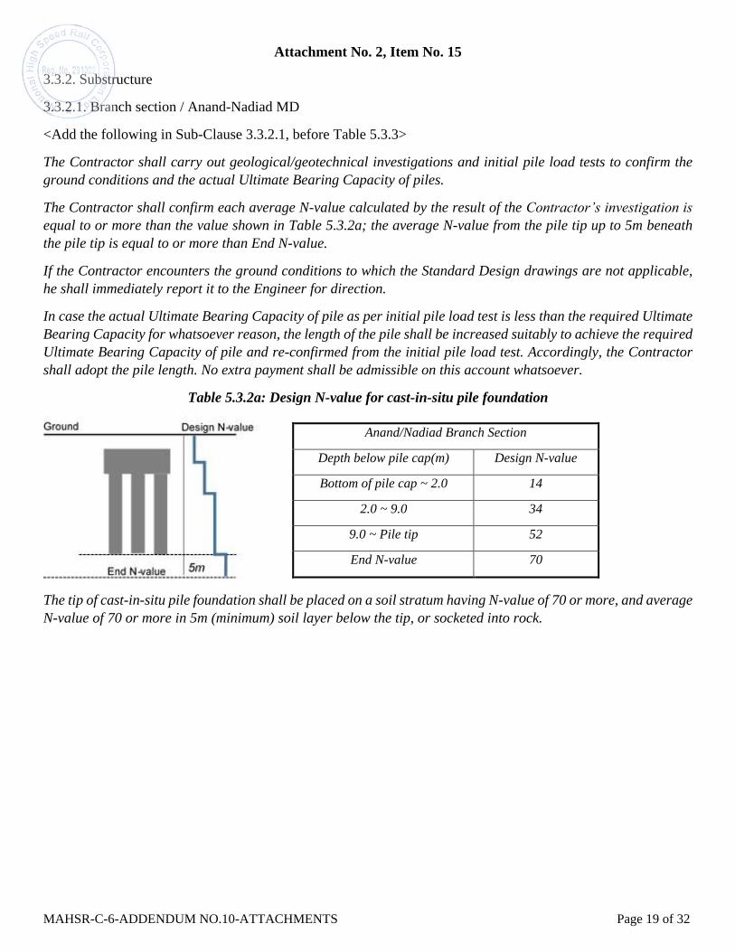
Attachment No. 2, Item No. 15
3.3.2. Substructure
3.3.2.1. Branch section / Anand-Nadiad MD
<Add the following in Sub-Clause 3.3.2.1, before Table 5.3.3>
The Contractor shall carry out geological/geotechnical investigations and initial pile load tests to confirm the
ground conditions and the actual Ultimate Bearing Capacity of piles.
The Contractor shall confirm each average N-value calculated by the result of the Contractor’s investigation is
equal to or more than the value shown in Table 5.3.2a; the average N-value from the pile tip up to 5m beneath
the pile tip is equal to or more than End N-value.
If the Contractor encounters the ground conditions to which the Standard Design drawings are not applicable,
he shall immediately report it to the Engineer for direction.
In case the actual Ultimate Bearing Capacity of pile as per initial pile load test is less than the required Ultimate
Bearing Capacity for whatsoever reason, the length of the pile shall be increased suitably to achieve the required
Ultimate Bearing Capacity of pile and re-confirmed from the initial pile load test. Accordingly, the Contractor
shall adopt the pile length. No extra payment shall be admissible on this account whatsoever.
Table 5.3.2a: Design N-value for cast-in-situ pile foundation
The tip of cast-in-situ pile foundation shall be placed on a soil stratum having N-value of 70 or more, and average
N-value of 70 or more in 5m (minimum) soil layer below the tip, or socketed into rock.
Anand/Nadiad Branch Section
Depth below pile cap(m) Design N-value
Bottom of pile cap ~ 2.0 14
2.0 ~ 9.0 34
9.0 ~ Pile tip 52
End N-value 70

MAHSR-C-6-ADDENDUM NO.10-ATTACHMENTS Page 20 of 32
Attachment No. 3, Item No. 26

MAHSR-C-6-ADDENDUM NO.10-ATTACHMENTS Page 21 of 32
Form ELI -1: Bidder Information Form
Date: [insert day, month, year]
IFB No.: Package No. MAHSR-C-6
Page [insert page number] of [insert total number] pages
[Bidders shall provide the following information.]
Bidder's legal name: [insert full name]
In case of a JV/Consortium, legal name of the representative member and of each member:
[insert full name of each member in the JV/Consortium and specify the representative
member.]
Bidder's actual or intended country of registration:
[insert country of registration]
Bidder's actual or intended year of incorporation:
[insert year of incorporation]
Bidder's legal address in country of registration:
[insert street/ number/ town or city/ country]
Bidder's authorized representative information:
Name: [insert full name]
Address: [inset street/ number/ town or city/ country]
Telephone/Fax numbers: [insert telephone/fax numbers, including country and city codes]
E-mail address: [insert E-mail address]
Attached are copies of original documents of:
Articles of Incorporation (or equivalent documents of constitution or association), and/or
documents of registration of legal entity named above, in accordance with ITB 4.3.
In case of JV, letter of intent to form JV or JV agreement, in accordance with ITB 4.1.
Included are the organizational chart, a list of Board of Directors, and the beneficial
ownership.
Bidder’s Representative:
Signature: ………………….…
Name: ………………….…….
Position: ………………….….
Date: …………………………..
Company: ……………………..
Company stamp: ………………
MAHSR-C-6-ADDENDUM NO.10-ATTACHMENTS Page 22 of 32
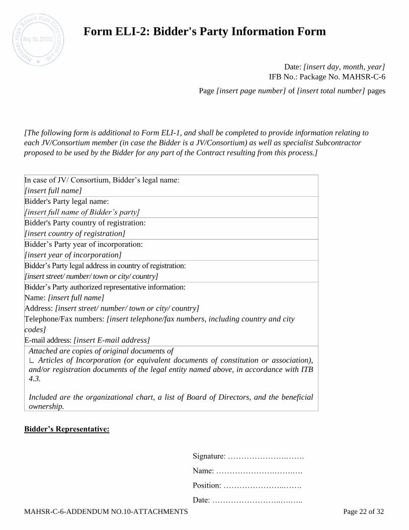
Form ELI-2: Bidder's Party Information Form
Date: [insert day, month, year]
IFB No.: Package No. MAHSR-C-6
Page [insert page number] of [insert total number] pages
[The following form is additional to Form ELI-1, and shall be completed to provide information relating to
each JV/Consortium member (in case the Bidder is a JV/Consortium) as well as specialist Subcontractor
proposed to be used by the Bidder for any part of the Contract resulting from this process.]
In case of JV/ Consortium, Bidder’s legal name:
[insert full name]
Bidder's Party legal name:
[insert full name of Bidder’s party]
Bidder's Party country of registration:
[insert country of registration]
Bidder’s Party year of incorporation:
[insert year of incorporation]
Bidder’s Party legal address in country of registration:
[insert street/ number/ town or city/ country]
Bidder’s Party authorized representative information:
Name: [insert full name]
Address: [insert street/ number/ town or city/ country]
Telephone/Fax numbers: [insert telephone/fax numbers, including country and city
codes]
E-mail address: [insert E-mail address]
Attached are copies of original documents of
Articles of Incorporation (or equivalent documents of constitution or association),
and/or registration documents of the legal entity named above, in accordance with ITB
4.3.
Included are the organizational chart, a list of Board of Directors, and the beneficial
ownership.
Bidder’s Representative:
Signature: ………………….…….
Name: ………………….…….….
Position: …………………..…….
Date: ……………………..….…..
MAHSR-C-6-ADDENDUM NO.10-ATTACHMENTS Page 23 of 32
Company: ………………..….…..
Company stamp: …….………..…
MAHSR-C-6-ADDENDUM NO.10-ATTACHMENTS Page 24 of 32
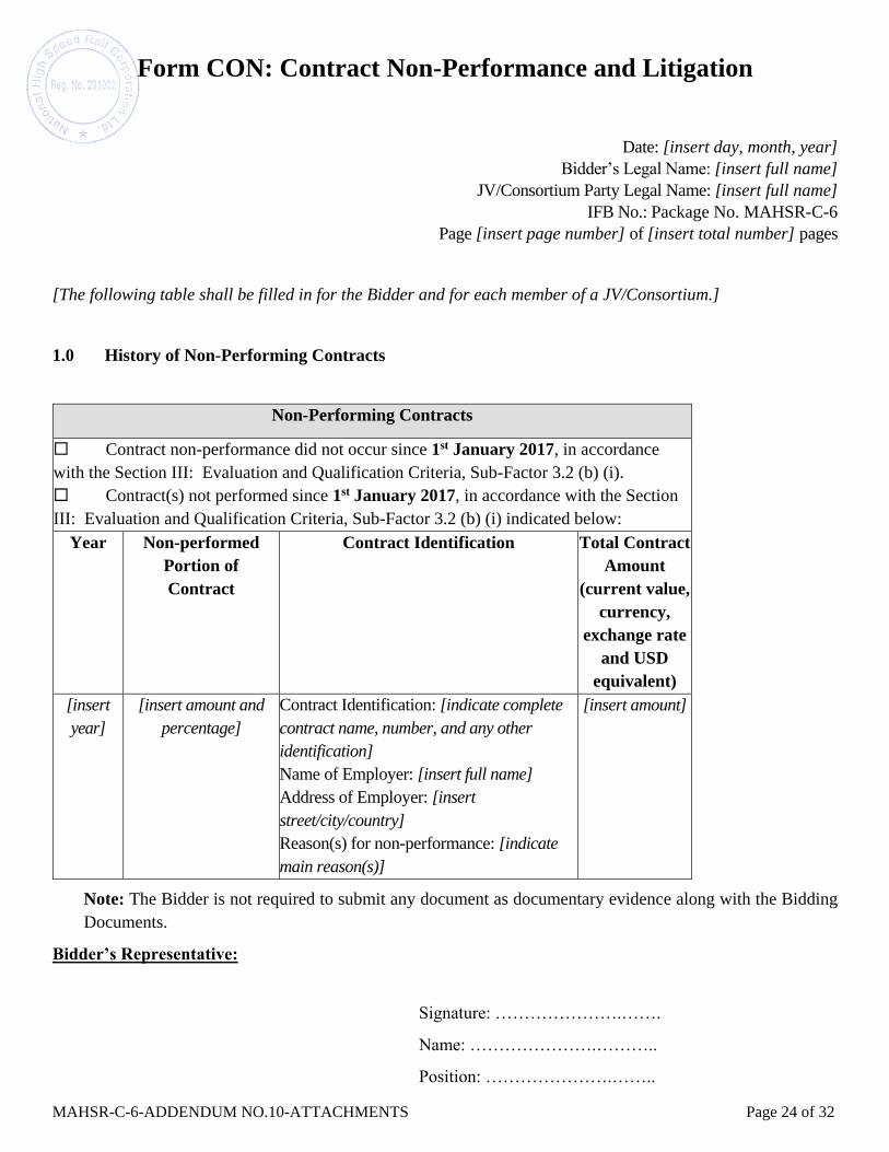
Form CON: Contract Non-Performance and Litigation
Date: [insert day, month, year]
Bidder’s Legal Name: [insert full name]
JV/Consortium Party Legal Name: [insert full name]
IFB No.: Package No. MAHSR-C-6
Page [insert page number] of [insert total number] pages
[The following table shall be filled in for the Bidder and for each member of a JV/Consortium.]
1.0 History of Non-Performing Contracts
Non-Performing Contracts
Contract non-performance did not occur since 1st January 2017, in accordance
with the Section III: Evaluation and Qualification Criteria, Sub-Factor 3.2 (b) (i).
Contract(s) not performed since 1st January 2017, in accordance with the Section
III: Evaluation and Qualification Criteria, Sub-Factor 3.2 (b) (i) indicated below:
Year Non-performed
Portion of
Contract
Contract Identification
Total Contract
Amount
(current value,
currency,
exchange rate
and USD
equivalent)
[insert
year]
[insert amount and
percentage]
Contract Identification: [indicate complete
contract name, number, and any other
identification]
Name of Employer: [insert full name]
Address of Employer: [insert
street/city/country]
Reason(s) for non-performance: [indicate
main reason(s)]
[insert amount]
Note: The Bidder is not required to submit any document as documentary evidence along with the Bidding
Documents.
Bidder’s Representative:
Signature: ………………….…….
Name: ………………….………..
Position: ………………….……..

MAHSR-C-6-ADDENDUM NO.10-ATTACHMENTS Page 25 of 32
Date: …………………………….
Company: ……………………….
Company stamp: …………………
MAHSR-C-6-ADDENDUM NO.10-ATTACHMENTS Page 26 of 32
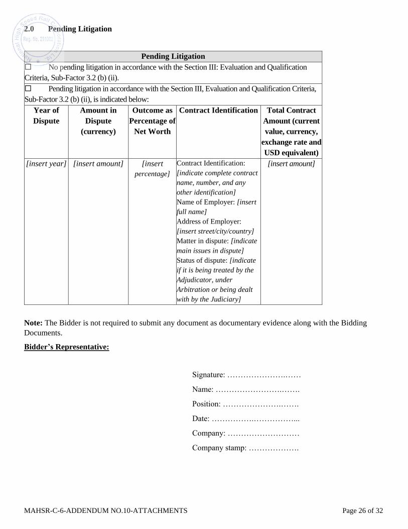
2.0 Pending Litigation
Pending Litigation
No pending litigation in accordance with the Section III: Evaluation and Qualification
Criteria, Sub-Factor 3.2 (b) (ii).
Pending litigation in accordance with the Section III, Evaluation and Qualification Criteria,
Sub-Factor 3.2 (b) (ii), is indicated below:
Year of
Dispute
Amount in
Dispute
(currency)
Outcome as
Percentage of
Net Worth
Contract Identification Total Contract
Amount (current
value, currency,
exchange rate and
USD equivalent)
[insert year] [insert amount] [insert
percentage]
Contract Identification:
[indicate complete contract
name, number, and any
other identification]
Name of Employer: [insert
full name]
Address of Employer:
[insert street/city/country]
Matter in dispute: [indicate
main issues in dispute]
Status of dispute: [indicate
if it is being treated by the
Adjudicator, under
Arbitration or being dealt
with by the Judiciary]
[insert amount]
Note: The Bidder is not required to submit any document as documentary evidence along with the Bidding
Documents.
Bidder’s Representative:
Signature: ………………….……
Name: …………………….…….
Position: ………………….…….
Date: …………….……………...
Company: ………………………
Company stamp: ……………….

MAHSR-C-6-ADDENDUM NO.10-ATTACHMENTS Page 27 of 32
3.0 Litigation History
Litigation History
No court/arbitral award decisions against the Bidder or any member of the
JV/consortium since 1st January 2015 up to 28 days prior to the Bid Submission deadline,
in accordance with the Section III, Evaluation and Qualification Criteria, Sub-Factor 3.2 (b)
(iii).
Court/ arbitral award decisions against the Bidder or any member of the JV/consortium
since 1st January 2015 up to 28 days prior to the Bid Submission deadline, in accordance
with the Section III, Evaluation and Qualification Criteria, Sub-Factor 3.2 (b) (iii), are
indicated below:
Year of
Award
Contract Identification Total Contract
Amount (current
value, currency,
exchange rate and
USD equivalent)
[insert year] Contract Identification: [indicate complete contract
name, number, and any other identification]
Name of Employer: [insert full name]
Address of Employer: [insert street/city/country]
Matter in dispute: [indicate main issues in dispute]
Party who initiated the dispute: [indicate
“Employer” or “Contractor”]
Status of dispute: [Indicate if it is being treated by
the Adjudicator, under Arbitration or being dealt
with by the Judiciary]
[insert amount]
Note: The Bidder is not required to submit any document as documentary evidence along with the Bidding
Documents.
Bidder’s Representative:
Signature: ……………………
Name: ………………………..
Position: ……………………..
Date: ………………….……..
Company: ……………………..
Company stamp: ……………….

MAHSR-C-6-ADDENDUM NO.10-ATTACHMENTS Page 28 of 32
Form EXP -1: General Construction Experience
[The following table shall be filled in for the Bidder and for each member of a JV/Consortium]
Date: [insert day, month, year]
Bidder’s Legal Name: [insert full name]
JV/Consortium Party Legal Name: [insert full name]
IFB No.: Package No. MAHSR-C-6
Page [insert page number] of [insert total number] pages
[Identify contracts that demonstrate continuous construction work over the past five (5) years pursuant to
Section III, Evaluation and Qualification Criteria,
Sub-Factor 3.2 (d) (i). List contracts chronologically, according to their commencement (starting) dates.]
General Construction Experience
Starting
Year
Ending
Year
Contract Identification Role of
Bidder
[indicate
year]
[indicate
year]
Contract name: [insert full name]
Brief description of the works performed by the
Bidder: [describe works performed briefly]
Amount of contract: [insert amount, currency,
exchange rate and USD equivalent]
Name of Employer: [indicate full name]
Address: [indicate street/number/town or
city/country]
[insert “Prime
Contractor” (single
entity or
JV/Consortium
member) or
"Subcontractor” or
“Management
Contractor”]
Note: The Bidder is required to submit the documentary evidence for the information furnished in the form.
Bidder’s Representative:
Signature: …………………….
Name: ………………………..
Position: ……………………..
Date: ………………………….
Company: ……………..……..
Company stamp: ……….……
MAHSR-C-6-ADDENDUM NO.10-ATTACHMENTS Page 29 of 32
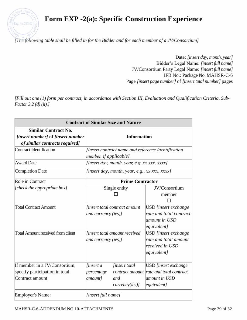
Form EXP -2(a): Specific Construction Experience
[The following table shall be filled in for the Bidder and for each member of a JV/Consortium]
Date: [insert day, month, year]
Bidder’s Legal Name: [insert full name]
JV/Consortium Party Legal Name: [insert full name]
IFB No.: Package No. MAHSR-C-6
Page [insert page number] of [insert total number] pages
[Fill out one (1) form per contract, in accordance with Section III, Evaluation and Qualification Criteria, Sub-
Factor 3.2 (d) (ii).]
Contract of Similar Size and Nature
Similar Contract No.
[insert number] of [insert number
of similar contracts required]
Information
Contract Identification [insert contract name and reference identification
number, if applicable]
Award Date [insert day, month, year, e.g. xx xxx, xxxx]
Completion Date [insert day, month, year, e.g., xx xxx, xxxx]
Role in Contract
[check the appropriate box]
Prime Contractor
Single entity
JV/Consortium
member
Total Contract Amount [insert total contract amount
and currency (ies)]
USD [insert exchange
rate and total contract
amount in USD
equivalent]
Total Amount received from client [insert total amount received
and currency (ies)]
USD [insert exchange
rate and total amount
received in USD
equivalent]
If member in a JV/Consortium,
specify participation in total
Contract amount
[insert a
percentage
amount]
[insert total
contract amount
and
currency(ies)]
USD [insert exchange
rate and total contract
amount in USD
equivalent]
Employer's Name: [insert full name]

MAHSR-C-6-ADDENDUM NO.10-ATTACHMENTS Page 30 of 32
Address:
Telephone/fax number
E-mail:
[indicate street / number / town or city / country]
[insert telephone/fax numbers, including country and
city area codes]
[insert E-mail address, if available]
Similar Contract No.
[insert number] of [insert number of
similar contracts required]
Information
Description of the similarity in
accordance with Sub-Factor 3.2
(d) (ii) of Section III:
1. Physical size of required works
items
Linear length of bridges/viaduct
(superstructure {concrete},
substructure {concrete} and
foundation) for metro
railway/railway
Note: Bridges/Viaduct under
various contracts can be added
to meet the above criteria.
[insert physical size of items]
2. Complexity [insert description of complexity]
3. Methods/Technology [insert specific aspects of the methods/technology
involved in the contract]
4. Other Characteristics [insert other characteristics as described in
Section VI-1. Employer’s Requirements - General
Specifications, Section VI-2. Employer’s
Requirements – Design Requirements and Criteria
and VI-3. Employer’s Requirements-Technical
Specifications].
Note: The Bidder is required to submit the documentary evidence for the information furnished in the form. The
Completion/Substantial Completion Certificates indicating the nature/scope of work, actual completion cost and
actual date of completion for such work shall be submitted duly certified from the Client.
Bidder’s Representative:
Signature: ………………….…….
Name: ………….………….…….
Position: ………………….…….
Date: ………….………………..
Company: ……………………..
Company stamp: …………………

MAHSR-C-6-ADDENDUM NO.10-ATTACHMENTS Page 31 of 32
Form EXP -2(b): Construction Experience in Key Activities
Date: [insert day, month, year]
Bidder’s Legal Name: [insert full name]
JV/Consortium Party Legal Name: [insert full name]
Subcontractor’s Legal Name [insert full name]
IFB No.: Package No. MAHSR-C-6
Page [insert page number] of [insert total number] pages
[Fill out one (1) form per contract, in accordance with Section III, Evaluation and Qualification Criteria, Sub-
Factor 3.2 (d) (iii).]
Key Activities:
Design and construction of following:
a. Three (3) km of bridge/viaduct for metro railway/railway (including length for elevated station).
b. Elevated/underground station for metro railway/railway.
Total Quantity of Activity under the Contract:
Key Activity a. ___________________________________
Key Activity b. ___________________________________
Contract with Similar Key Activities
Item Information
Contract Identification [insert contract name and number, if applicable]
Award Date [insert day, month, year, e.g., xx, xxx, xxxx]
Completion Date [insert day, month, year, e.g., xx, xxx, xxxx]
Role in Contract
[check the appropriate box]
Prime Contractor
Management
Contractor
Subcontractor
Single
entity
JV/Consortium
member
Total Contract Amount [insert total contract amount
in INR]
USD [insert
Exchange rate and total
contract amount in USD
equivalent]
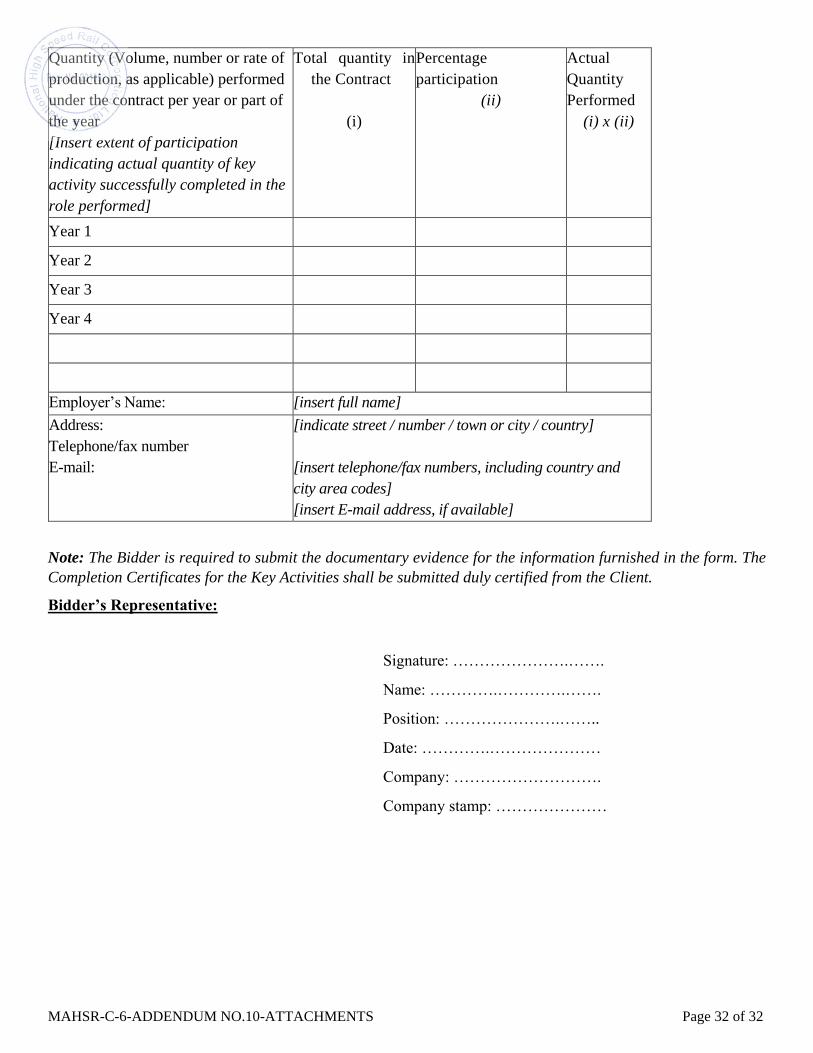
MAHSR-C-6-ADDENDUM NO.10-ATTACHMENTS Page 32 of 32
Quantity (Volume, number or rate of
production, as applicable) performed
under the contract per year or part of
the year
[Insert extent of participation
indicating actual quantity of key
activity successfully completed in the
role performed]
Total quantity in
the Contract
(i)
Percentage
participation
(ii)
Actual
Quantity
Performed
(i) x (ii)
Year 1
Year 2
Year 3
Year 4
Employer’s Name: [insert full name]
Address:
Telephone/fax number
E-mail:
[indicate street / number / town or city / country]
[insert telephone/fax numbers, including country and
city area codes]
[insert E-mail address, if available]
Note: The Bidder is required to submit the documentary evidence for the information furnished in the form. The
Completion Certificates for the Key Activities shall be submitted duly certified from the Client.
Bidder’s Representative:
Signature: ………………….…….
Name: ………….………….…….
Position: ………………….……..
Date: ………….…………………
Company: ……………………….
Company stamp: …………………