National Grid Substations Technical Specification NGTS 2.1 ... · PDF filesubstation including...
27
National Grid Substations Technical Specification NGTS 2.1 Issue 2 May 1995 CONTENTS Page Foreword ....................... 1 Scope ......................... 1 References ..................... 1 General Requirements ............ 2 Performance Requirements ....... 12 Test Requirements .............. 14 Appendix A .................... 17 Appendix B .................... 21 Appendix C .................... 23 Authorised for Issue by: M B Humphries General Manager Technology and Science Division The Electrical Standards for SHE Transmission’s area are non-maintained versions of National Grid Technical Specifications that are applicable to the SHE Transmission System only. These specific versions are not subject to National Grid change control and all queries about their applicability and content should be directed to SHE Transmission in the first instance. (Should Users require the change controlled versions of the GB Transmission System National Grid Technical Specifications please see the National Grid Extranet or Livelink system where applicable).
-
Upload
nguyenkhuong -
Category
Documents
-
view
235 -
download
3
Transcript of National Grid Substations Technical Specification NGTS 2.1 ... · PDF filesubstation including...

National Grid SubstationsTechnicalSpecification
NGTS 2.1Issue 2May 1995
CONTENTS Page
Foreword . . . . . . . . . . . . . . . . . . . . . . . 1Scope . . . . . . . . . . . . . . . . . . . . . . . . . 1References . . . . . . . . . . . . . . . . . . . . . 1General Requirements . . . . . . . . . . . . 2Performance Requirements . . . . . . . 12Test Requirements . . . . . . . . . . . . . . 14Appendix A . . . . . . . . . . . . . . . . . . . . 17Appendix B . . . . . . . . . . . . . . . . . . . . 21Appendix C . . . . . . . . . . . . . . . . . . . . 23
Authorised for Issue by:
M B HumphriesGeneral ManagerTechnology and Science Division
The Electrical Standards for SHETransmission’s area are non-maintainedversions of National Grid TechnicalSpecifications that are applicable to the SHETransmission System only. These specificversions are not subject to National Gridchange control and all queries about theirapplicability and content should be directed toSHE Transmission in the first instance. (ShouldUsers require the change controlled versionsof the GB Transmission System National GridTechnical Specifications please see theNational Grid Extranet or Livelink systemwhere applicable).
© The National Grid Company plc 1995
No part of this publication may be reproduced,stored in a retrieval system, or transmitted inany form or by any means electronic, mechanical,photocopying, recording or otherwise, withoutthe written permission of the NGC obtained fromthe issuing location.
Registered OfficeNational Grid HouseKirby Corner RoadCoventry CV4 8JY
Registered inEngland and WalesNo. 2366977
Published by:
The National Grid Company plcBurymead HousePortsmouth RoadGuildford, Surrey GU2 5BN

NGTS 2.1Page 1 Issue 2
May 1995
SUBSTATIONS
FOREWORD
This Document defines the technical requirements for substations connected to The National Grid Companyplc (NGC) system and with equipment rated at 145, 300 or 420 kV. It is supported by the more specificNGTS documents at Level 3.
This Specification is applicable to new construction and extensions to existing installations. It shouldhowever be noted that where a ‘Central Electricity Generating Board (CEGB) Standard' substation is to beextended the Contract may refer to obsolete Transmission Plant Specifications.
1 SCOPE
This functional Specification covers all types of substation with equipment installed for use on 132, 275 and400 kV 50 Hz systems. It is applicable to both open-terminal air-insulated (AIS) and metal-enclosed gas-insulated (GIS) substation constructions and covers equipment operated at lower voltages on the samesubstation site.
All NGC plant and apparatus wholly within the substation and not covered more specifically by other NGTS'sis within the scope of this document.
2 REFERENCES
The Health and Safety at Work Act 1974.
The Factories Act 1961.
The Electricity at Work Regulations 1989.
IEC 694 (BS 6581) Common Clauses for High-Voltage Switchgear and Controlgear Standards.
IEC 865 Calculation of the Effects of Short-Circuit Currents.
EN 50-052 High-Voltage Switchgear and Controlgear for Industrial Use. Cast Aluminium Alloy Enclosuresfor Gas-Filled High-Voltage Switchgear and Controlgear.
EN 50-064 Wrought Aluminium and Aluminium Alloy Enclosures for Gas-Filled High-Voltage Switchgearand Controlgear.
BS EN 50-068 Wrought Steel Enclosures for Gas-Filled High-Voltage Switchgear and Controlgear.
BS EN 50-069 Welded Composite Enclosures of Cast and Wrought Aluminium Alloys for Gas-Filled High-Voltage Switchgear and Controlgear.
BS EN 50-089 Cast Resin Partitions for Metal Enclosed Gas-Filled High-Voltage Switchgear andControlgear.
BS EN 60-529 Classification of Degrees of Protection Provided by Enclosures.
BS EN 61011 Safety Requirements for Mains Operated Electric Fence Energizers.
BS 1710 Specification for Identification of Pipelines and Services.
BS 5395: Part 3 Code of Practice for the Design of Industrial Type Stairs, Permanent Ladders andWalkways.
NGTS 2.1Page 2 Issue 2May 1995
BS 7354 Code of Practice for Design of High-Voltage Open-Terminal Substations.
NGTS 1 Overview, National Grid System.
NGTS 2.2 Switchgear for the National Grid System.
NGTS 2.13 Electronic Equipment.
NGTS 2.19 Ancillary Light Current Equipment .
NGTS 3.1.1 Substation Interlocking Schemes.
NGTS 3.1.2 Substation Earthing.
NGTS 3.1.3 Substation Auxiliary Supplies (Publication Mid 1995).
NGTS 3.2.2 Disconnectors and Earthing Switches.
3 GENERAL REQUIREMENTS
3.1 Requirements for all Substations
3.1.1 Statutory Requirements
In addition to the requirement specified in Clause 4.1 of NGTS 1, the manner in which plant and equipmentis installed as a system shall allow that system and its components to be operated and maintained withinthe requirements of principally The Health and Safety at Work etc Act 1974, The Factories Act 1961, TheElectricity at Work Regulations 1989, The Provision and Use of Work Equipment Regulations 1992 and TheElectricity Supply Regulations 1988 as amended 1990 and 1994. Particular attention shall be paid to safeaccess/egress from places of work and provision of a safe place of work.
3.1.2 Design Life of Installation
Unless otherwise specified by NGC, the substation installation including busbars, connections, insulatorsand structures shall be designed for a life of 40 years subject to periodic preventive maintenance beingcarried out in accordance with manufacturers or suppliers instructions.
Where part of the installation would require replacement or mid-life refurbishment to achieve the specifieddesign life then this shall be stated at the time of tendering. Tenderers shall declare the life cycle costs ofequipment on request.
3.1.3 Outage Constraints
Unless otherwise specified or agreed by NGC the design of the substation shall permit installation,extension, operation and maintenance (preventive and corrective) with a maximum of one circuit and onebusbar section out of service simultaneously. A busbar section is taken to be a part of either the main orreserve busbars. Associated busbar section and busbar coupler circuits may be considered to be part ofthe busbar section.
NGC shall be advised at the Tender stage of any areas in which the requirements of this clause cannot bemet.
The line conductors of different outgoing circuits shall not be crossed unless otherwise agreed by NGC.
3.1.4 Switchgear Local Control
The installation of switchgear shall comply with the requirements of Clause 3.3 of NGTS 2.2.

NGTS 2.1Page 3 Issue 2
May 1995
3.1.5 Operational Access
Reasonable access shall be provided to the isolation facilities of each disconnector and earthing switch,including the locking device, where fitted. Access shall comply with Clause 3.1.1 and shall be suitable foruse by an unaccompanied person.
Unless otherwise agreed with NGC the isolation facilities or locking devices shall be between 1 m and 1.8m above the floor level or platform provided for access and shall not be further than 750 mm horizontallyfrom the edge of a platform.
Access above ground level shall be from mobile or fixed platforms (though the latter may be accessed byladder). Where movement of equipment within the substation would be restricted by the presence of laddersit is acceptable that these should be removable. Removable ladders and mobile platforms shall be easilyhandled and used on the finished substation surface by one person.
Ladders and permanent platforms shall, where applicable, comply with BS 5395: Part 3. Other Standardsmay be acceptable by agreement with NGC.
3.1.6 Requirements for Maintenance
The substation layout shall make allowance for preventive or corrective maintenance within the outageconstraints specified in Clause 3.1.3 and using procedures compliant with Clause 3.1.1.
Access for maintenance shall be provided as follows:
(i) The substation layout and surfaces shall be adequate to allow the access and use of powered accessequipment, cranes and similar equipment required for any normal maintenance operation (circuit-breakerinterrupter change, disconnector contact change, insulator cleaning etc). Suitable sealed surface roadsshall be provided to substation main buildings and heavy items of plant (eg transformers), other surfacesshould be finished in accordance with NGTS 2.10.
(ii) Fixed platforms need not be provided for preventive or corrective maintenance requirements so long asaccess can be gained by the use of pre-formed scaffolding, portable ladders or, in outdoor substations,powered access equipment.
Arrangements of any fixed platforms provided shall be to the approval of NGC and shall meet therequirements of BS 5395: Part 3. Other Standards may be acceptable by agreement with NGC.
Maintenance shall be taken to include the replacement of any component or sub-component within thesubstation including GIS enclosures.
Suppliers shall, on request, provide a written procedure for carrying out any proposed maintenanceprocedure in accordance with these requirements.
3.1.7 Interlocking
Substations shall be provided with a full interlocking scheme as specified in NGTS 3.1.1.
Requirements of electronic interlocking schemes provided as part of substation control systems arespecified in NGTS 3.7.11.
3.1.8 Cranes & Lifting Equipment
Fixed cranes should not be provided in indoor AIS substations except where specifically required formaintenance or repair purposes. Fixed cranes shall be provided in indoor GIS substations except wherethe supplier can demonstrate specifically that they are not required for dismantling or removing any part ofthe substation for maintenance or repair purposes.

NGTS 2.1Page 4 Issue 2May 1995
Lifting beams or overhead cranes of adequate capacity shall be provided, where necessary, to assist indismantling switchgear. Provision shall be made to inspect beams or cranes for insurance purposes andfit lifting tackle within the outage constraints specified in Clause 3.1.3.
3.1.9 Facilities
The following facilities shall be provided at all new 400 kV and 275 kV substations.
(i) Adequate toilet and washing facilities for NGC operation and maintenance staff.
(ii) A standby control room, this shall have provision to be equipped as a permit office and to be used foron-site drawing/record storage. At indoor GIS substations access to the control room shall not be throughthe switchgear hall and the room shall be designed to prevent ingress of SF6/arc products in the event ofa switchgear fault.
(iii) At sites where SF6 gas-filled equipment is installed, a standing area and suitable water and drainageconnections for a mobile changing/shower facility. Such facilities are required to comply with NGC safetycodes of practice for work on SF6-filled equipment that has been exposed to power arcing.
(iv) A small mess room with sink.
(v) An equipment store/small workshop.
(vi) Vehicle parking.
The size of the mobile changing/shower facility and workshop will be specified by NGC.
The extent to which this Clause shall apply to 132 kV and lower voltage substations and extensions toexisting installations shall be specified by NGC.
3.1.10 Plant and Equipment Identification
Labels shall be provided to allow identification of all plant and equipment and associated operating facilitiesand points of isolation. The following are normally required:
(i) Each circuit-breaker, disconnector and earthing switch mechanism box shall carry a label giving the NGCoperational reference (to be specified by NGC) of the device.
(ii) For GIS equipment each partition between gas zones shall carry labels giving the identifier of the gaszone at each side of the partition.
(iii) Each pressure gauge or pressure readout device shall carry a label identifying the parameter it ismonitoring.
(iv) Each valve (including self-sealing gas filling valves) shall carry a label identifying its function.
(v) Each control handle or switch for plant operation shall carry a label identifying its function.
(vi) Each point of LV isolation associated with plant shall carry a label identifying its function.
(vii) Each cabinet, cubicle or kiosk shall carry a label identifying the equipment contained within it.
The detailed wording of labels shall be to the approval of NGC. The labels shall be sufficiently durable forthe application and environment in which they are to be used. Stencilling of items which may requirerepainting during the life of the substation shall not be acceptable.
3.1.11 Current Transformers
Unless otherwise agreed with NGC, the accommodation of current transformers shall be as specified inAppendix A and their location shall be as specified in Appendix B.
NGTS 2.1Page 5 Issue 2
May 1995
3.1.12 Voltage Transformer Secondary Isolation
Voltage transformer secondary isolation links, or other means of positive isolation to the approval of NGC,shall be provided in a separate isolation box mounted between 1 m and 1.8 m above substation floor oraccess platform level. The door of the isolation box shall be padlockable by means of NGC's standardpadlock type.
3.1.13 Compressed Air Storage Systems
Where required, a central compressed air storage system shall be provided, the technical requirements willbe specified in the Contract.
3.1.14 Substation Auxiliary Cable Routing
Cable trenches shall be used between main substation buildings and dispersed relay rooms or, in the caseof a central relay room, between the relay room and the common marshalling point for each primary circuit.Cables between dispersed relay rooms or circuit marshalling points and local plant may be buried directwhere armoured cables are used; in all other circumstances cable ducts may be used. In relay rooms andcontrol rooms cables shall be run in overhead racks and computer floors shall not be provided. The locationof all buried cables and ducts shall be adequately recorded.
3.1.15 Light Current Equipment
Electronic equipment shall be located in accommodation commensurate with its environmental performancewhich is classified in NGTS 2.13 and NGTS 2.6 as appropriate. Where reasonably practicable, co-locationof protection, control and measurement systems in a common room is preferred.
Heaters and/or dehumidifiers shall be provided in light current accommodation in order to meetthe requirements of NGTS 2.13 Class C (minimum ambient temperature -10bC, relative humidity 10-100%)under all ambient conditions. Where fixed heating is provided it shall be thermostatically controlled.
Where no fixed heating is provided, provision shall be made for raising the air temperature in the vicinity ofall equipment associated with any one circuit to 15bC without causing condensation on the equipment.
All panels housing secondary equipment sited in equipment rooms shall have provision to be padlocked.
3.1.16 Substation Earthing
Substation earthing systems shall be designed and installed in accordance with NGTS 3.1.2.
3.1.17 Substation Auxiliary Supplies
Substation auxiliary supplies shall be designed and installed in accordance with NGTS 3.1.3.
3.1.18 Environmental
The guidelines for substation siting and design given in Appendix C shall be followed, with particularattention paid to Clause C2.2 and Sections C3 and C4.
3.1.19 NGC will specify requirements for site security provisions and equipment on a site by site basis.The use of electric pulse security fences to BS EN 61011 is the preferred option for sites requiring highsecurity. Perimeter fences meeting statutory 2.4 m height requirements, incorporating electric pulse securitysystems on lower security sites, will be considered if it can be demonstrated that there is a cost benefit overthe use of NGC standard fencing over the life of the substation.
3.2 Requirements for AIS Substations
The layout of AIS shall be arranged to ensure the integrity of the air space between live parts and otherconductors (whether earthed or at different potential) for the rated voltage conditions for which the
NGTS 2.1Page 6 Issue 2May 1995
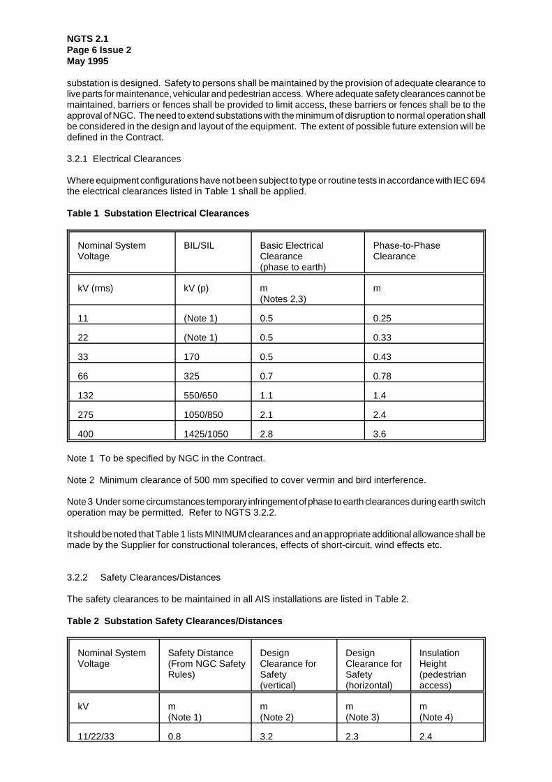
substation is designed. Safety to persons shall be maintained by the provision of adequate clearance tolive parts for maintenance, vehicular and pedestrian access. Where adequate safety clearances cannot bemaintained, barriers or fences shall be provided to limit access, these barriers or fences shall be to theapproval of NGC. The need to extend substations with the minimum of disruption to normal operation shallbe considered in the design and layout of the equipment. The extent of possible future extension will bedefined in the Contract.
3.2.1 Electrical Clearances
Where equipment configurations have not been subject to type or routine tests in accordance with IEC 694the electrical clearances listed in Table 1 shall be applied.
Table 1 Substation Electrical Clearances
Nominal SystemVoltage
BIL/SIL Basic ElectricalClearance(phase to earth)
Phase-to-PhaseClearance
kV (rms) kV (p) m(Notes 2,3)
m
11 (Note 1) 0.5 0.25
22 (Note 1) 0.5 0.33
33 170 0.5 0.43
66 325 0.7 0.78
132 550/650 1.1 1.4
275 1050/850 2.1 2.4
400 1425/1050 2.8 3.6
Note 1 To be specified by NGC in the Contract.
Note 2 Minimum clearance of 500 mm specified to cover vermin and bird interference.
Note 3 Under some circumstances temporary infringement of phase to earth clearances during earth switchoperation may be permitted. Refer to NGTS 3.2.2.
It should be noted that Table 1 lists MINIMUM clearances and an appropriate additional allowance shall bemade by the Supplier for constructional tolerances, effects of short-circuit, wind effects etc.
3.2.2 Safety Clearances/Distances
The safety clearances to be maintained in all AIS installations are listed in Table 2.
Table 2 Substation Safety Clearances/Distances
Nominal SystemVoltage
Safety Distance(From NGC SafetyRules)
DesignClearance forSafety(vertical)
DesignClearance forSafety(horizontal)
InsulationHeight(pedestrianaccess)
kV m(Note 1)
m(Note 2)
m(Note 3)
m(Note 4)
11/22/33 0.8 3.2 2.3 2.4

NGTS 2.1Page 7 Issue 2
May 1995
Nominal SystemVoltage
Safety Distance(From NGC SafetyRules)
DesignClearance forSafety(vertical)
DesignClearance forSafety(horizontal)
InsulationHeight(pedestrianaccess)
66 1.0 3.4 2.5 2.4
132 1.4 3.8 2.9 2.4
275 2.4 4.8 3.9 2.4
400 3.1 5.5 4.6 2.4
It should be noted that Table 2 lists MINIMUM clearances and an appropriate additional allowance shall bemade by the Supplier for constructional tolerances.
Note 1 Persons shall not allow any part of their body or any object to infringe this distance to exposedconductors operated at high voltage.
Note 2 The minimum clearance from a live conductor to a point to which pedestrian access is permitted.
These figures are derived by adding the 'personal reach' (the vertical reach of a person with upstretchedhand), which is taken to be 2.4 m, to the appropriate Safety Clearance.
These figures should be taken as the 'section clearance' when this dimension is considered in the substationdesign.
Note 3 These figures may be used by agreement with NGC. In general the vertical design clearance shouldbe applied in all directions.
Note 4 The minimum clearance from the lowest insulation part of a support insulator to a point to whichpedestrian access is permitted.
3.2.3 Clearance to Roadways
The clearances to roadways to which vehicular access is required shall, unless otherwise agreed by NGC,allow unrestricted movement of a 2.4 m high vehicle. To comply with NGC safety codes of practice andobviate the need to use temporary earthing the clearances from live conductors to a 2.4 m high vehiclespanning the full width of the roadway shall be as listed in Table 2, Design Clearance for Safety (vertical).
Height barriers shall be provided at entrances to the substation and/or within the substation to restrictaccess for vehicles exceeding the maximum height for which unrestricted access is allowable. Thesebarriers shall be designed to be opened and shall have a facility to apply a padlock to secure them in theclosed position.
3.2.4 Substation Profile
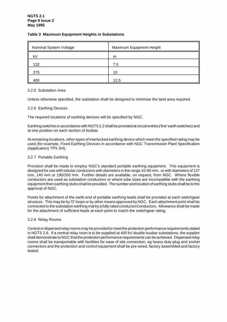
To limit the environmental impact of the substation the height of the highest component of outdoorsubstations should be kept to a practical minimum to achieve a low substation profile. Unless otherwiseagreed by NGC, on new sites maximum heights of equipment shall not exceed the values listed in Table3. At existing sites the height of existing equipment shall not be exceeded.
NGTS 2.1Page 8 Issue 2May 1995
Table 3 Maximum Equipment Heights in Substations
Nominal System Voltage Maximum Equipment Height
kV m
132 7.5
275 10
400 12.5
3.2.5 Substation Area
Unless otherwise specified, the substation shall be designed to minimise the land area required.
3.2.6 Earthing Devices
The required locations of earthing devices will be specified by NGC.
Earthing switches in accordance with NGTS 2.2 shall be provided at circuit entries ('line' earth switches) andat one position on each section of busbar.
At remaining locations, other types of interlocked earthing device which meet the specified rating may beused (for example, Fixed Earthing Devices in accordance with NGC Transmission Plant Specification(Application) TPS 3/4).
3.2.7 Portable Earthing
Provision shall be made to employ NGC's standard portable earthing equipment. This equipment isdesigned for use with tubular conductors with diameters in the range 10-90 mm, or with diameters of 127mm, 140 mm or 190/200 mm. Further details are available, on request, from NGC. Where flexibleconductors are used as substation conductors or where tube sizes are incompatible with the earthingequipment then earthing stubs shall be provided. The number and location of earthing stubs shall be to theapproval of NGC.
Points for attachment of the earth end of portable earthing leads shall be provided at each switchgearstructure. This may be by 'D' loops or by other means approved by NGC. Each attachment point shall beconnected to the substation earthing mat by a fully rated conductor/conductors. Allowance shall be madefor the attachment of sufficient leads at each point to match the switchgear rating.
3.2.8 Relay Rooms
Central or dispersed relay rooms may be provided to meet the protection performance requirements statedin NGTS 2.6. If a central relay room is to be supplied at 400 kV double busbar substations, the suppliershall demonstrate to NGC that the protection performance requirements can be achieved. Dispersed relayrooms shall be transportable with facilities for ease of site connection, eg heavy duty plug and socketconnectors and the protection and control equipment shall be pre-wired, factory assembled and factorytested.

NGTS 2.1Page 9 Issue 2
May 1995
3.3 Requirements for GIS Substations
The following requirements apply to phase-segregated GIS designs with a rated voltage of 300 or 420 kV.They shall also apply, where appropriate, to lower voltage designs, however in this case the extent ofcompliance required shall be subject to agreement with NGC.
3.3.1 Buildings
GIS installations comprising two or more circuit breakers shall be housed in a building so as to minimiseerection and life cycle maintenance costs. The building shall be of minimum cost construction consistentwith environmental and planning requirements.
3.3.2 AIS Connections
Where AIS connections are associated with a GIS substation then the requirements listed under 3.2 shallapply to those connections.
3.3.3 Segregation of Gas Zones
The equipment shall be segregated into sufficient independent gas zones to allow the requirements ofClause 3.1.6 to be met. Unless otherwise agreed with NGC, circuit-breakers shall be accommodated inseparate gas zones from other equipment.
3.3.4 Gas Zone Barriers
Gas zone barriers (partitions) shall be designed to withstand the differential pressures to which they maybe subjected during preventive or corrective maintenance. A reduction of the dielectric properties ofadjacent gas zones containing live high-voltage conductors by lowering gas pressures will not beacceptable.
3.3.5 Portable Maintenance Earthing Devices
Provision shall be made for fitting Portable Maintenance Earthing Devices (PMED's) where these arerequired to permit maintenance/testing. The principal applications of PMED's are to allow an earthing switchthat would normally be the point of earthing, to be itself maintained and to earth cable sealing ends with theisolation link removed.
The PMED's shall be rated in accordance with the requirements of NGTS 2.2.
Proposals for the location of PMED positions shall be submitted to NGC for approval before the substationdesign is finalised.
Positions at which PMED's may be fitted shall be identified by painting the access covers green. ThePMED's shall be identified by painting in a red/white striped pattern externally so that they can be clearlyseen when in position. Other alternative means of identification may be employed to the approval of NGC.
Two three-phase sets of PMED's shall be supplied for each substation or, if the PMED's are of more thanone type, two three-phase sets of each type shall be supplied.
3.3.6 Disconnector Lock-Out If the GIS disconnectors supplied cannot be demonstrated to perform their rated duties when filled with SF6gas at atmospheric pressure then arrangements shall be made to prevent operation when gas density islower than the 'low' alarm setting.
3.3.7 SF6 Gas Service Connections
The gas service connection for each gas zone shall be readily accessible without the use of special accessequipment. Proposed access arrangements shall be to the approval of NGC.
A schematic diagram shall be provided showing the gas zones within a bay and their relationship to the

NGTS 2.1Page 10 Issue 2May 1995
primary plant of that circuit or busbar section. Where gas service connections are grouped together thediagram shall be displayed adjacent to this point, otherwise it shall be displayed at the Local Control Cabinet(LCC).
Filling points shall be fitted with self-sealing valves of a design to the approval of NGC. Gas service valves,lockable by means of NGC's standard padlock type, shall also be provided at each filling point.Alternatively, where self-sealing valves are fitted directly to the enclosures, a lockable cover to preventunauthorised access to the valve shall be provided. This cover shall be lockable by means of NGC'sstandard padlock.
Provision shall be made for the use of an in-line dust filter at each filling point, either by permanentlyinstalling a filter at each point or providing a separate filter that can be fitted between the gas service hoseand the self-sealing valve.
3.3.8 Pressure/Density Indication
Facilities for indicating the gas pressure or density in each gas zone shall be provided. Systems offeringfacilities for remote indication are preferred. Where the indication is of density this shall be displayed as anequivalent pressure at a reference temperature. The equipment shall be permanently installed and alldisplays shall be readable from the substation floor level or from access walkways.
3.3.9 SF6 Gas Alarm Scheme
Each gas zone shall be fitted with a density monitor with two falling alarm settings. These shall be set tothe switchgear manufacturers recommended 'falling' and 'low' alarm densities and shall be connected to thesubstation alarm scheme. The grouping of 'low' alarms at the normal substation control point shall be suchthat the section of equipment which requires isolation from the system can be readily identified.
Where leakage of gas from a high pressure gas zone to an adjacent lower pressure gas zone may resultin the rupture of the pressure relief device of the lower pressure zone before a falling pressure alarm isreceived from the high pressure zone then the lower pressure zone shall be fitted with a high density alarm.
For indoor substations, an audible alarm scheme shall be provided in the substation building to warnoperators of a major loss of SF6 gas. This shall be connected to operate at the low pressure alarm settingof each gas zone. Controls shall be provided at the substation control point to reset and isolate the audiblealarm. Visual indications shall be provided in the switchhouse, to show that the audible alarm is in serviceand outside the main entrances to the switchhouse, to indicate that the alarm has operated. Provision shallbe made to isolate the alarm contact of each gas zone independently so that individual alarms can bedisabled during maintenance, such isolation shall not prevent the receipt of a 'low' pressure alarm at thecontrol points.
Each density monitor shall be provided with a means of checking initiation of the 'falling' and 'low' densityalarms without reducing the pressure in the main compartment. The method of providing this facility shallbe to the approval of NGC.
3.3.10 Bursting Discs & Explosion Vents
Bursting discs and explosion vents shall be installed so as to eject debris away from normally accessibleareas. They shall be set to minimise danger to personnel.
3.3.11 Identification of Pipework
Fixed gas and hydraulic pipework shall be identified in accordance with BS 1710.
3.3.12 Identification of Gas Zone Barriers
The position of each non-breathing gas zone partition shall be clearly identified by painting the flange of theGIS enclosure where the partition is fitted in a distinctive colour.

NGTS 2.1Page 11 Issue 2
May 1995
Labels shall be fixed to the enclosure at each non-breathing gas zone partition showing the identifier of thegas zones at each side of that partition.
3.3.13 Cable Testing
Where high voltage cables are terminated directly in GIS enclosures then provision must be made for D.C.cable testing.
The point of disconnection for cable testing and the connections between it and the cable shall bedemonstrated to meet the requirements of NGTS 2.2 for D.C. withstand voltage.
In all cases a fixed or temporary earthing device shall be provided for applying an earth between the pointof isolation and the cable sealing end. It shall be possible to apply this earthing device using an insulatedtool to the approval of NGC and leave it in place while making or breaking the point of isolation.
Where specified, provision shall be made for installing a D.C. test bushing to allow cables to be tested fromthe substation end. Where a test bushing is not supplied as part of the Contract then the installation shallbe designed to permit the use of one of NGC's existing bushings. Details of available bushings will besupplied on request.
Suppliers shall provide details of proposed cable testing arrangements with Tenders.
3.3.14 Primary Injection Testing of CT's
Provision shall be made for carrying out primary injection tests on all current transformers without requiringinternal access to any chamber.
3.3.15 Partial Discharge Measurement
Capacitive couplers for diagnostic monitoring of the GIS equipment and transient voltage measurementsare required to be located in all phases at the sealing ends of each cable connected circuit, at the SF6 sideof each transformer bushing and adjacent to the SF6/air bushings of each circuit connected to AISequipment. In addition couplers shall be located in all phases at approximately 20 m intervals betweenthese points such that all parts of the GIS equipment are between two couplers and no more than 20 m fromeither of these couplers. Proposals shall be to the approval of NGC.
To facilitate the use of couplers for in-service monitoring, coupler signal connections shall be cabled toground level and suitable test boxes provided at locations agreed with NGC. Signal connections in the testbox shall be N series 50 ohm sockets. To limit interference, cables between the couplers and test boxesshall be double screened co-axial.
3.3.16 Desiccant
All gas zones shall have desiccant material provided in each phase to assist in the absorption of watervapour and gaseous acidic products.
3.3.17 Location of Light Current Equipment
Equipment panels may be located in the switchgear building either adjacent to the switchgear, generallyconforming to bay widths, or in an annexe. Such equipment, together with its accommodation, shall meetthe requirements of Class IP 54 of BS EN 60 529.
3.4 Requirements for Earthing Systems and Earthing of Plant
The requirements for earthing systems and earthing of plant are defined in NGTS 3.1.2.

NGTS 2.1Page 12 Issue 2May 1995
4 PERFORMANCE REQUIREMENTS
4.1 Requirements for all Switchgear
4.1.1 Jointing of Current Carrying Conductors
The method of jointing site-assembled current carrying conductors (except those internal to GIS equipment)shall be such as to avoid electrochemical reactions or the effects of corrosion. Such joints shall be expectedto have a service life of at least 40 years. Jointing methods shall be to the approval of NGC.
4.2 Requirements for AIS
4.2.1 Mechanical Design
Equipment shall be designed to withstand the maximum force to which it may be subjected in its lifetime.In order to establish the total mechanical forces acting on equipment and supporting structures it isnecessary that consideration be given to forces resulting from:
(a) Short-circuit current
(b) Wind loading
(c) Deadweight
(d) Ice covering
(e) Conductor tension
These forces shall be calculated in accordance with Section 3.2 of BS 7354:1990 and factors of safetyapplied in accordance with Section 3.3.
Other internationally recognised Specifications or Standards may be acceptable as an alternative toBS 7354 subject to the agreement of NGC.
Where the design of equipment imposes additional forces to those listed above, then the Supplier shall takeaccount of these forces in his design.
4.2.2 Busbars, Connections & Connectors
These shall be rated for normal current, short time withstand current and maximum radio interferencevoltage in accordance with NGTS 2.2 and IEC 694.
Table 6 of IEC 865: Recommended Highest Temperatures for Mechanically StressedConductors during a Short Circuit
Type of conductor Maximum recommended conductortemperature during a short circuit
Bare conductors, solid or stranded:Cu, Al or Al alloy
200bC
Bare conductors, solid or stranded:steel
300bC

NGTS 2.1Page 13 Issue 2
May 1995
Table 4 Recommended Highest Temperatures for Non-Mechanically Stressed ConductorsDuring a Short Circuit
Type of conductor Maximum recommended conductortemperature during a short circuit
Bare conductors, solid or stranded:Cu
405bC
Bare conductors, solid or stranded:Al or Al alloy
325bC
Bare conductors, solid or stranded:steel
300bC
The maximum conductor temperature after passage of rated short time current shall not exceed therecommended values given in table 6 of IEC 865 for mechanically stressed conductors and Table 4 abovefor non mechanically stressed conductors. The initial conductor temperature shall be taken to be the ratedmaximum ambient temperature for the equipment. Table 6 of IEC 865 is reproduced on the preceding pagefor clarity.
4.3 Requirements for GIS
4.3.1 Pressurised Gas-Filled Enclosures
These shall be designed and manufactured in accordance with the following CENELEC Standards:
EN 50-052EN 50-064BS EN 50-068BS EN 50-069
4.3.2 Cast Resin Partitions
Cast resin partitions (barriers) shall be designed and manufactured in accordance with CENELEC StandardEN 50-089.
4.3.3 Internal Arcing
In principle, the gas zones, when at design pressure, shall show no external effect resulting from an internalarc of rated short-time current for a duration not less than the maximum main protection fault clearance time.On small gas zones, operation of the safety device may occur within main protection fault clearance time.When gas zones are subjected to an internal arc of rated short-time current for a duration not less than theback-up or breaker-fail protection fault clearance time, the resulting effect shall be restricted to operationof the safety pressure relief device(s) or the appearance of a hole, provided there is no ejection offragmented parts.
The fault clearance times to be used in assessing this performance are as follows:
Rated Voltage(kV)
Main Protection(ms)
Back-Up or Breaker FailProtection (ms)
420 140 300
300 160 500
145 180 1000
Compliance with this requirement shall be demonstrated by means of calculations or tests. On equipmenthaving three phases in a common enclosure, or gas zone, allowance shall be made for the possibility of

NGTS 2.1Page 14 Issue 2May 1995
faults evolving to include two or more phases.
4.3.4 Couplers for Partial Discharge Measurement
Partial discharge couplers (the requirement for which is specified in Clause 3.3.15) shall be sensitive to allfrequencies in the range 0.1 - 1.5 GHz and shall give an output signal suitable for a spectrum analyser.
Couplers shall have a linear response in the frequency range 50 Hz - 300 MHZ and a capability to makeD.C. 'trapped charge' measurements.
5 TEST REQUIREMENTS
5.1 Type Tests
5.1.1 Busbars, Connections & Connectors
Electrical type tests shall be performed in accordance with IEC 694.
Tests of mechanical performance shall be subject to agreement between the Supplier and NGC dependanton the application.
5.1.2 Pressurised Gas-Filled Enclosures
These shall be tested, where applicable, in accordance with the following CENELEC Standards:
EN 50-052EN 50-064BS EN 50-068BS EN 50-069
5.1.3 Cast Resin Partitions
Cast resin partitions (barriers) shall be tested in accordance with CENELEC Standard EN 50-089.
5.2 Routine Tests at Manufacturers Works
5.2.1 Pressurised Gas-Filled Enclosures
These shall be tested in accordance with the following CENELEC Standards:
EN 50-052EN 50-064BS EN 50-068BS EN 50-069
5.2.2 Cast Resin Partitions
Cast resin partitions (barriers) shall be tested in accordance with CENELEC Standard EN 50-089.
5.3 Routine Tests at Site
5.3.1 Current Carrying Conductors
Where joints between current carrying conductors are made on site then the joint electrical resistance shallbe measured and recorded.

NGTS 2.1Page 15 Issue 2
May 1995
5.3.2 Partial Discharge Tests (GIS)
Partial discharge activity shall be monitored throughout the site power-frequency high voltage tests of GISequipment.
Suppliers shall state the maximum acceptable partial discharge level during the site test at 1.1 U/B3. Thismeasurement shall be made on reducing voltage following the power frequency withstand test. The partialdischarge level at nominal voltage shall also be recorded.

NGTS 2.1Page 16 Issue 2May 1995

NGTS 2.1Page 17 Issue 2
May 1995
APPENDIX A
CURRENT TRANSFORMER ACCOMMODATION
A1 CURRENT TRANSFORMER MOUNTING AND POLARITY MARKINGS
The following conventions shall be adopted for the physical mounting of current transformers with respectto their terminal markings:
(i) In circuit-breakers, all P1 markings shall be electrically nearer to the circuit-breaker than thecorresponding P2 markings.
(ii) In transformers, reactors or generators, the P1 markings shall be electrically nearer to the windings thanthe corresponding P2 markings.
(iii) For separately mounted current transformers, if they are associated with the circuit-breaker, they shallbe considered as though they were an integral part of the circuit-breaker. If separately mounted currenttransformers are not associated with the circuit-breakers, the P1 markings shall be electrically nearer to thejunction of the primary connections or busbars than the corresponding P2 markings.
(iv) In the run of busbars, and not associated with a circuit-breaker, the current transformers will usually bein the same housing or chamber. In this case the P1 marking should be electrically nearer the section ofbusbars with the higher number. If there are two housings or chambers (per phase), the P1 markings ofeach shall be electrically nearer the adjacent housing or chamber.
The current transformer accommodation normally available for use is as detailed in A2 to A7 below. In eachcase the current transformer cores are listed in the preferred order with the housing, Core 1 being positionednearest to the P1 terminal.
A2 POST TYPE CURRENT TRANSFORMERS AND THROUGH WALL AIR/AIR BUSHINGS
All 420, 300 and 145 kV post type measurement/protection CTs and through wall air/air bushings shall haveaccommodation for a minimum of four current transformer cores using one of the arrangements listed below.Accommodation for CTs for high accuracy metering purposes shall be as detailed in NGTS 3.2.6.
The following 'standard' configurations of CT cores are commonly used by NGC. Alternative configurationsmay be accepted or specified on a contract basis:
A2.1 Five Core Arrangement
A full complement of five secondary windings as follows:
Core 1 Protection Type ACore 2 Protection Type ACore 3 Measurement/ProtectionCore 4 Protection Type BCore 5 Protection Type B
This arrangement will be required where older types of high-burden protection/instrumentation are installed.

NGTS 2.1Page 18 Issue 2May 1995
A2.2 Four Core Arrangement
A complement of four secondary windings as follows:
Core 1 Protection Type ACore 2 Protection Type ACore 3 Protection Type BCore 4 Protection Type B
This is the preferred arrangement for circuit CT's in new substations with digital protection/instrumentationsystems.
A3 AIS DEAD-TANK AND GIS CIRCUIT-BREAKERS
Circuit-breaker bushings, bushing turrets or CT enclosures on the line side of the circuit-breaker shall becapable of accommodating four or five secondary windings in arrangements A2.1 or A2.2, as required bythe application. For busbar coupler and section applications CT accommodation shall be provided on eachside of the circuit-breaker.
A4 GIS BACK PARTS
In switchgear making up a mesh, or single switch substation additional accommodation is required for fouror five current transformers in each feeder circuit connection, the arrangement being as A2.1 or A2.2.
A5 TRANSFORMER AND SHUNT REACTOR BUSHING TURRETS
The accommodation available in the turrets of bushings shall allow for a maximum of four currenttransformer windings, excluding those which may be required for winding temperature indicators, as follows:
Core 1 Protection Type BCore 2 Measurement/ProtectionCore 3 Protection Type ACore 4 Protection Type A
The allocation of current transformer cores to particular transformers will depend upon the protectionrequirements of the local primary systems to which the transformer is connected.
A6 SLIP-OVER, NEUTRAL AND OTHER SEPARATELY MOUNTED CURRENTTRANSFORMERS
Accommodation requirements for such applications are to be examined individually to establish thatsufficient accommodation exists for the current transformer types required.

NGTS 2.1Page 19 Issue 2
May 1995
A7 THE NEUTRAL AND NEUTRAL END CONNECTIONS OF TRANSFORMER AND SHUNTREACTORS
For neutral current transformers associated with double-wound grid transformers and supergrid auto-transformers, and neutral end current transformers associated with supergrid auto-transformers,accommodation shall be provided as follows:
(i) Neutral current transformer housings shall provide accommodation for at least three current transformerwindings as follows:
Core 1 Protection Type BCore 2 Measurement/ProtectionCore 3 Measurement/Protection
(ii) Neutral end current transformer housings shall provide accommodation for one Protection Type Bcurrent transformer winding per phase.
(iii) Combined neutral and neutral-end current transformer housings shall provide accommodation for atleast two neutral current transformer windings as follows:
Core 1 Protection Type B (one current transformer per phase)Core 2 Measurement/Protection (one only - on neutral conductor)Core 3 Measurement/Protection (one only - on neutral conductor)
For neutral and neutral end current transformers associated with supergrid shunt reactors, accommodationshall be provided as follows:
(i) Neutral end current transformer housings shall provide accommodation for one Protection Type B currenttransformer per phase.
(ii) Neutral current transformer housings shall provide accommodation for one Measurement/Protectioncurrent transformer.

NGTS 2.1Page 20 Issue 2May 1995

NGTS 2.1Page 21 Issue 2
May 1995
APPENDIX B
LOCATION OF CURRENT TRANSFORMERS ASSOCIATED WITH 420, 300 AND 145 kVCIRCUIT BREAKERS
B1 GENERAL
In all installations where current transformer housings are associated with circuit-breakers such housingsshall be mounted as close as possible to the circuit-breaker concerned.
B2 BUSBAR STATIONS
B2.1 Circuits Other than Bus Section or Bus Coupler
All current transformers associated with a given circuit-breaker shall be installed on the circuit side of thecircuit-breaker.
B2.2 Bus Section and Bus Coupler Circuits
Current transformers for busbar protection shall be installed on both sides of the circuit-breaker; the currenttransformer for a particular zone of protection being located on the side of the circuit-breaker remote fromthe zone.
Current transformers for commissioning overcurrent and back up earth fault protection shall be installed onthe reserve busbar side of the bus coupler circuit-breaker and on the lower numbered main or reservebusbar side (as appropriate) of the bus section circuit-breaker.
Current transformers for system back-up protection shall be installed in the bushings or housings on thereserve busbar side of the bus-coupler circuit-breaker and on the lower numbered main or reserve busbarside (as appropriate) of the bus-section circuit-breaker. The current transformers shall preferably be of theMeasurement/Protection type but, where there is only one set of such current transformers in the correctlocation, Type A current transformers shall be used instead; this will normally only apply where post-typecurrent transformers are employed.
Current transformers for instrumentation purposes and circuit-breaker fail protection shall be installed onthe main busbar side of the bus-coupler circuit-breaker and on the higher numbered main or reserve busbarside (as appropriate) of the bus-section circuit-breaker.
B3 MESH TYPE STATIONS
Current transformers for feeder protection, feeder instrumentation purposes and for system back-upprotection shall be installed in the line current transformer housing.
Current transformers for bus section instrumentation purposes and circuit-breaker fail protection shall beinstalled in the bushings or housings on the side of the circuit-breaker which connects to the mesh cornerhaving the corresponding number eg mesh corner four side of S40 etc.
Current transformers for mesh-corner protection shall be installed in the line current transformer housing,in the HV bushing turrets of the associated transformer(s) and on both sides of the circuit-breakers, thecurrent transformer for a particular zone of protection being located on the side of the circuit-breaker remotefrom that zone.

NGTS 2.1Page 22 Issue 2May 1995
B4 SINGLE SWITCH STATIONS
Current transformers for feeder protection and for feeder instrumentation purposes shall be installed in theline current transformer housings.
Current transformers for system back-up protection shall be installed in the line current transformer housingsand in the bushings or housings on the higher numbered side of the bus section circuit-breaker; the currenttransformer for system back-up protection shall also be used for circuit-breaker fail protection.
Current transformers for bus section instrumentation purposes shall be installed in the bushing or housingson the lower numbered zone side of the bus section circuit-breaker.
Current transformers for mesh corner protection shall be installed in the line current transformer housings,the HV bushing turrets of the associated transformer(s) and in the bushings or housings on both sides ofthe bus section circuit-breaker, the current transformer for a particular zone or protection being located onthe side of the circuit-breaker remote from that zone.

NGTS 2.1Page 23 Issue 2
May 1995
APPENDIX C
NGC SUBSTATIONS AND THE ENVIRONMENT: EXTRACT FROM GUIDELINES ON SITINGAND DESIGN
C1 OVERALL SYSTEM OPTIONS AND SITE SELECTION
In the development of system options including new substations, consideration must be given toenvironmental issues from the earliest stage to balance the technical benefits and capital cost requirementsfor new developments against the consequential environmental effects in order to keep their adverse impactto a reasonably practicable minimum.
C2 LOCAL CONTEXT, LAND USE AND SITE PLANNING
C2.1 The siting of substations, extensions and associated proposals should take advantage of thescreening provided by land form and existing features and the potential use of site layout and levels to keepintrusion into surrounding areas to a reasonably practicable minimum.
Notes:
1 A preliminary study should be undertaken to identify the extent of land required to meet both operationaland environmental needs.
2 In some instances it may be possible to site a substation partially or fully enclosed by existing woodlands.
3 Topographical information should be obtained at an early stage. In some cases a geotechnical surveymay be required.
C2.2 The proposals should keep the visual, noise and other environmental effects to a reasonablypracticable minimum.
Notes:
1 Allow sufficient space for screening of views by mounding or planting.
2 Consider appropriate noise attention measures where necessary.
3 Use security measures which minimise visual intrusion from lighting.
4 Consider appropriate on site water pollution prevention measures.
5 Consider adjoining uses and the amenity of local inhabitants.
C2.3 The land use effects of the proposal should be considered when planning the siting of substations orextensions.
Notes:
1 Issues for consideration include potential sterilisation of nationally important land, eg Grade 1 agriculturalland and sites of nationally scarce minerals.
2 Effects on land drainage.
NGTS 2.1Page 24 Issue 2May 1995
C3 DESIGN
C3.1 In the design of new substations or line entries, early consideration should be given to the optionsavailable for terminal towers, equipment, buildings and ancillary development appropriate to individuallocations, seeking to keep effects to a reasonably practicable minimum.
Notes:
1 With outdoor equipment, a preference should be given normally to a low profile design with low heightstructures and silhouettes appropriate to the background.
2 Use lightweight narrow section materials for taller structures especially for gantries over 6 metres inheight.
3 Commission exterior design and colours appropriate to the surroundings.
4 Materials and colours for buildings, equipment and fencing should be chosen to harmonise with localsurroundings.
5 Where possible, avoid the use of prominent insulators by consideration of available colours appropriateto the background.
6 Where possible site buildings to act as visual screens for switchgear.
7 Ensure that the design of high voltage and low voltage substations is coordinated by early consultationbetween NGC and its customers.
8 Where there are particular technical or environmental constraints, it may be appropriate to consider theuse of Gas Insulated Switchgear (GIS) equipment which occupies less space and is usually enclosed withinthe building.
9 Early consideration should be given to the routing of utility service connections.
C3.2 Space should be used effectively to limit the area required for development consistent withappropriate mitigation measures and to minimise the adverse effects on existing land use and rights of way,whilst also having regard to the future extension of the substation.
Notes:
1 Assess the benefit of removing redundant substation equipment from existing sites where this wouldimprove their appearance.
C3.3 The design of access roads, perimeter fencing, earthshaping, planting and ancillary developmentshould from an integral part of the site layout and design to fit in with the surroundings.
C4 LINE ENTRIES
C4.1 In open landscape especially, high voltage line entries should be kept, as far as possible, visuallyseparate from low voltage lines and other overhead lines so as to avoid a confusing appearance.
C4.2 The inter-relationship between towers and substation structures and background and foregroundfeatures should be studied to reduce the prominence of structures from main viewpoint. Where practicablethe exposure of terminal towers on prominent ridges should be minimised by siting towers against abackground of trees rather than open skylines.

RECORD OF REVISION
NGTS 2.1
This issue (Issue 2) has been revised and amended as follows:
REV DATE DETAILS OF REVISION AUTHORISATION
May 1995 Numerous Revisions(Identified in documentMargin) as a result ofmajor review