
National Grid Small Business Program Rebate Manual
28
National Grid Small Business Program Rebate Manual
Transcript of National Grid Small Business Program Rebate Manual

National Grid Small Business Program Rebate Manual

Rebate Manual
Munro Distributing has prepared this manual to aid you and your clients in taking advantage of available rebate programs offered by National Grid.
The enclosed product guide includes fixtures that apply to local prescriptive utility rebate programs. Use of products indicated does not guarantee a rebate. Please contact your local utility and/or Munro Distributing for any questions or concerns pertaining to your project. In addition to those listed, other products may be eligible for rebates. Please contact your Munro Distributing representative for assistance.
Please visit our website for updated Energy Services information regarding new products, links to informative sites and beneficial analysis tools. Please visit us at www.munroelectric.com.
Munro Distributing – 800.777.0172
6/27/10
2

Lighting Controls
112

Lighting ControlsDescription Manufacturer Model
Warranty (years)
Page Number
CEILING MNT, LOW VOLT ULTRA SONIC UP TO 500 SQFT Wattstopper W500A 5 114- 115
CEILING MNT, LOW VOLT ULTRA SONIC >500 SQFT Wattstopper W1000A 5 114- 115CEILING MNT, LOW VOLT PASSIVE INFRARED UP TO 500 SQFT Sensor Switch CM 9 5 116- 117CEILING MNT, LOW VOLT PASSIVE INFRARED >500 SQFT Sensor Switch CM 10 5 118- 119CEILING MNT, LOW VOLT DUAL TECH UP TO 500 SQFT Sensor Switch CM PDT 9 5 120- 121
CEILING MNT, LOW VOLT DUAL TECH >500 SQFT Sensor Switch CM PDT 10 5 122- 123POWER PACK FOR LOW VOLT SENSORS, UNV VOLTAGE Sensor Switch/Wattstopper MP20/BZ50 5 124- 127
SWITCH MNT, PASSIVE INFRARED Sensor Switch WSD WH 5 128- 129
SWITCH MNT, PASSIVE INFRARED 2 POLE Sensor Switch WSD 2P WH 5 130- 131
SWITCH MNT, DUAL TECHNOLOGY Sensor Switch WSD PDT WH 5 132- 133
FIXTURE MNT, HIF - LINE VOLTAGE Sensor Switch CMRB 6 5 134- 135
FIXTURE MNT, FLOUR. - LINE VOLTAGE Sensor Switch CMRB 6 5 134- 135
PHOTO CELL Intermatic K4221 5 136
TIME CLOCK Intermatic T101 5 137
113

PROJECT
LOCATION/TYPE
www.wattstopper.com8 0 0 . 8 7 9 . 8 5 8 5
CO
MM
ER
CIA
L O
CC
UP
AN
CY
SE
NS
OR
S &
CO
NT
RO
LS
W Series Ultrasonic Ceiling Sensors
• ASP circuitry helps to eliminate false on
• Utilizes advanced omni-directional, ultrasonic technology for reliable occupancy detection
• Omni-directional transmission provides 360° of coverage
• Time delay adjustable from 15 seconds to 15 minutes
WattStopper’s W Series Ultrasonic Ceiling Sensors are versatile motion detectors that control lighting in a wide variety of applications. W Series Sensors can be used individually or as part of an integrated system of WattStopper lighting control products.
Manual-on Option
Applications
Ultrasonic sensors effectively control offices, restrooms, utility areas, open office spaces and warehouses. The W-500A is perfect for offices, conference rooms, restrooms and other areas up to 500 square feet. The W-1000A fits in larger spaces, such as storage areas. The W-2000A is ideal for open office areas or large warehouses and can control partitioned open office spaces when configured in highly versatile zone patterns. The W-2000H reliably covers hallways with walls.
Operation
The 24 VDC W Series Sensors utilize advanced omni-directional, ultrasonic technology to sense occupancy. When movement is detected in a controlled area, the W Series Sensors will switch lights on via low-voltage wiring through to a WattStopper power or auxiliary pack. Once the area is vacated and the user-adjustable time delay (15 seconds to 15 minutes) has elapsed, lighting systems automatically switch off.
DescriptionProduct Overview
Features • 500, 1000, 2000-square foot and hallway cover-age available to fit needs of specific applications
• Optional on override by installing the Override Pin provided with the sensor
• LED indicates occupancy detection
• Qualifies for ARRA-funded public works projects
Adjustable time delay from 15 seconds to 15 minutes
To comply with code or for additional control options, W Series Sensors can be used with a BZ-150 power pack for manual-on/auto-off control. If this option is selected, occupants utilize a low-voltage momentary wall switch to turn on lights. Lights automatically turn off after the area is vacated and the user-adjustable time delay has elapsed.
Turns lights on and off based on occupancy to reduce energy costs
Hallway and 500, 1000 and 2000 square foot coverage available
Advanced Signal Processing (ASP) circuitry automatically adjusts detection threshold
Ideal for open office areas,conference rooms and restrooms
Automatic or manual-on operation when used with a BZ-150 Power Pack
114

www.wattstopper.com | 8 0 0 . 8 7 9 . 8 5 8 5
CO
MM
ER
CIA
L O
CC
UP
AN
CY
SE
NS
OR
S &
CO
NT
RO
LS
A typical layout for an open office space would be to place W-2000A sensors so they control zones that overlap. For partitioned spaces, a typical zone is about 25’ x 25’ with an overlap on the coverage that senses motion up to 30’ x 30’.
30' x 30'
Wiring
Coverage,Installation
& Placement
Pub. No. 0114 rev. 10/2009
Ordering Information
Specifications • Solid state, crystal-controlled (25 kHz ± 0.005%)• Temperature and humidity-resistant 25 kHz
receivers: W-500A contains one receiver, other models contain two receivers
• Adjustable time delay: 15 seconds to 15 minutes
• Mounting options: ceiling tile, 4” sq. junction box• Max. units per power pack: B = seven; BZ = nine• Dimensions: 4.5” x 4.5” x 1.25” (115mm x 115mm x 32mm) W x L x D• UL listed• Five year warranty
W-500AW-500A-FTAW-500A-UW-1000AW-1000A-FTAW-1000A-UW-2000AW-2000A-FTAW-2000A-UW-2000HW-2000H-FTA W-2000H-U
24 VDC
24 VDC
24 VDC
24 VDC
Catalog No. Voltage Current Coverage
All units are white and use WattStopper power packs. **Coverage for an enclosed hallway is 10’ x 90’ (see pattern above).
16 mA
16 mA
16 mA
16 mA
360°; 500 ft2 (46.5 m2)
360°; 1000 ft2 (92.9 m2)
360°; 2000 ft2 (185.8 m2)
360°; 90 linear ft (27.4 m)**
Standard Wiring Diagram
Installation
Multiple Sensor Wiring Diagram
Coverage Pattern
Open Office Sensor PlacementEnclosed Office Sensor Placement
Neutral
Hot
Switch
Red
Red
White
Black Red
Bla
ckB
lue
PowerPack
LoadLoad
Occupancy Sensor
BLU Control Output
BLK Common
RED +24VDC
Power Pack
Occupancy Sensor
N White
Hot Black
Red (line)
Red (load)
Occupancy Sensor
BLU Control Output
BLK Common
RED +24VDC
LOAD
White (neutral)
5'
10'
12'
20'
20'
12'
5'
10'
5'20'25'45' 25'15' 45'
29'
24' **W-2000H
W-2000A
W-1000A
W-500A
sensor
20'
Coverage shown represent half-step walking motion. Actual coverage can vary for each application depending on the shape and the use of space and the obstacles present. Coverage may be reduced if product is mounted greater than 12 feet high.
The W-2000H drawing is not drawn to scale. Coverage is 10’ x 90’ in a hallway; enclosed spaces enhance coverage.
Receiver
Sensitivity
Time delay
Bypass LED
Attach sensor to a vibration-free surface. Mount the sensors with the receivers facing the area of coverage. Note: Ultrasonic sensors should be placed 4’ away from supply ducts, 6’ from horizontal discharge ducts, and 6” from power packs.
Sens
Fixtures
15' x 20'
Sensor
Fixtures
15' x 20'
Figure A Figure B For enclosed spaces, place sensors as in Figure A. Sensors placed as in Figure B may see out the door and cause false triggers.Correct Incorrect
115

®
SPECIFICATIONS
ORDERING INFO
OPTIONS
LOW VOLTAGE RELAY (R)• Enables sensors to interface with
other systems (e.g., BMS, lighting panels)
• Provides dry contact closure via a SPDT, 1 Amp, 40 Volt relay
• Only one relay needed per zone• Changes state when all connected
sensors register unoccupied• Relay requires sensor power to
function
OCCUPANCY CONTROLLED DIMMING (D)• Provides dimming output to control
0-10 VDC dimmable ballasts• Provides a second occupancy time-
out period that enables the lights to go to a dim setting before turning off
• Adjustable max/min dim setting
PHOTOCELL (P)• Auto set-point calibration• Two selectable modes of operation• On/Off mode: Photocell has full
control during periods of occupancy• Inhibit mode: Photocell can prevent
lights from turning on if adequate daylight is available, but cannot turn lights off
PHOTOCELL W/ DIMMING (ADC)• Photocell within sensor maintains total
room light level by controlling levels of 0-10 VDC dimmable ballasts
• Photocell also has full on/off control during periods of occupancy
• Provides a second occupancy time-out period that enables the lights to go to a dim setting before turning off
LOW TEMP/HIGH HUMIDITY (LT)• Sensor is corrosion resistant to
moisture • Operates down to -40º F/C
The CM 9 Series occupancy sensor offers
amazing performance and sensitivity
to small motions for a standard range
Passive Infrared (PIR) sensor. Ideal for
small rooms with drop ceilings and areas
without obstructions, the CM 9 is a snap
to install. Its light weight allows surface
mounting to drop ceilings or a ceiling
grid. The CM 9 sensor can cover entire
private offices or smaller rooms by itself,
however it is also the ideal lead sensor for
odd shaped rooms. For example, a CM 9
in a restroom vestibule can communicate
with a CM PDT 9 Dual Technology sensor
in a main stall area. Another application
is a CM 9 covering an entrance hall to a
classroom and communicating with a WV PDT 16 sensor covering the main room. In
both cases the lights would be activated
on by the CM 9. For mounting above 15
ft (4.57 m), see the CM 6 Technical Data
Sheet.
SENSOR OPERATIONThe sensor detects changes in the
infrared energy given off by occupants
as they move within the field-of-view.
When occupancy is detected, a DC
output goes high and can drive up to
200 mA of connected load. The sensor
is powered with 12-24 VAC/VDC and
typically operates with a PP20 or MP20
power pack, enabling complete 20 Amp
circuits to be controlled. An internal timer,
factory set at 10 minutes, keeps the lights
on during brief periods of inactivity. This
timer is push-button programmable from
30 seconds to 20 minutes, and is reset
every time occupancy is re-detected. This
state-of-the-art design requires no field
calibration or sensitivity adjustments.
STANDARD RANGE 360º SENSOR ������������ ����������� ������������������������
CM 9
FEATURES PIR Occupancy Detection 360º Coverage Push-Button Programmable Adjustable Time Delay 100 Hr Lamp Burn-in Timer Green LED Indicator
PHYSICAL SPECS SIZE 4.55” Dia. (11.56 cm) 1.55” Deep (3.94 cm) WEIGHT 6 oz MOUNTING Ceiling Tile Surface 3.5” Octagon Box Single Gang Handy Box COLOR White
ELECTRICAL SPECS OPERATING VOLTAGE 12-24 VAC/VDC CURRENT DRAW Standard, 4 mA w/ R option, 16 mA DIMMING LOAD Sinks / Sources < 20mA;
~40 Ballasts @ .5mA each
RECOMMENDED POWER PACK
PP20
ENVIRONMENTAL SPECS OPERATING TEMP 14º to 160º F (-10º to 71º C) STORAGE TEMP -14º to 160º F (-26º to 71º C) RELATIVE HUMIDITY 20 to 90% non-condensing
OTHER UL and CUL Listed Title 24 Compliant 5 Year Warranty Made in the U.S.A.
RELAY TEMP/HUMIDITY
Blank = None Blank = None Blank = Standard R = Low Voltage Relay D = Occupancy Controlled Dimming LT = Low Temp P = Photocell ADC = Photocell w/ Dimming
CM 9 [RELAY] [DIMMING/PHOTOCELL] [TEMP/HUMIDITY]
ONS
DIMMING / PHOTOCELL CHOOSE ONE ONLY
116

900 Northrop Road, Wallingford, CT 06492 • 1.800.PASSIVE • FX 203.269.9621 • www.sensorswitch.com
WARRANTY: Sensor Switch, Inc. warrants these products to be free of defects in manufacture and workmanship for a
period of 60 months. Sensor Switch, Inc., upon prompt notice of such defect, will, at its option, provide a Returned Material
Authorization number and repair or replace returned product.
LIMITATIONS AND EXCLUSIONS: This Warranty is in full lieu of all other representation and expressed and implied
warranties (including the implied warranties of merchantability and fitness for use) and under no circumstances shall
Sensor Switch, Inc. be liable for any incidental or consequential property damages or losses. T002-005
Revised 07.01.09 © 2009 Sensor Switch, Inc.
INSTALLATION
WIRING (DO NOT WIRE HOT)
COVERAGE PATTERN
12 6 0 ft 6 12
3.7 1.8 0 m 1.8 3.7
���������0 ft
9
0 m
2.7
������
12
6
0 ft
6
12
3.7
1.8
0 m
1.8
3.7
9 STANDARD RANGE 360º LENS Note: Screw axis is
aligned with a long
detection segment
STANDARD WIRINGRED - Power Input (12-24 VAC/VDC)
BLACK - Common
WHITE - Output (high VDC for occupancy)
RELAY OPTION (R)GRAY / BROWN - Connected during occupied state
VIOLET / BROWN - Connected during unoccupied state
Note: Relay is energized during unoccupied state
PHOTOCELL OPTIONS (P, ADC)BLUE - Use in place of White ouput wire. Photocell
output is high VDC with occupancy & low light.
For multi-level control, use two power packs and connect
White to primary load and Blue to daylight load.
DIMMING OPTIONS (D, ADC)VIOLET w/ WHITE STRIPE - Connect to Violet control
wire from 0-10 VDC dimmable ballast
GRAY from Ballast - Connect to sensor Black wire
• Best choice for small motion (e.g. hand movements)
detection
• Viewing angle of 56º in a 360º conical shaped pattern
• Provides 12 ft (3.66 m) radial coverage when mounted to
standard 9 ft (2.74 m) ceiling
• 8 to 15 ft (2.44 to 4.57 m) mounting heights provide 10 to
20 ft (3.05 to 6.10 m) radial coverage
[R] Relay Option
[P, ADC] Photocell Options
[ADC, D] Dimming Options
POWER PACK(PP20)RED
WHTBLK
VIO w/ WHT STRIPE (+)( - )
PUSH BUTTON
PROGRAMMINGRefer to included instruction card for default settings and directions on programming the sensor via the push-button.
• Mount sensor directly to a ceiling tile or a metallic grid (two
self-tapping screws provided).
• Sensor’s mounting holes also align with 3.5” octagon or
single gang handy box (screws not provided).
• Sensor will detect motions crossing segments more
effectively than motions parallel to beams.
• For optimal detection, position sensor such that segments
are crossed upon entrance and unable to view outside the
space.
117

®
SPECIFICATIONS
ORDERING INFO
OPTIONS
LOW VOLTAGE RELAY (R)• Enables sensors to interface with
other systems (e.g., BMS, lighting panels)
• Provides dry contact closure via a SPDT, 1 Amp, 40 Volt relay
• Only one relay needed per zone• Changes state when all connected
sensors register unoccupied• Relay requires sensor power to
function
OCCUPANCY CONTROLLED DIMMING (D)• Provides dimming output to control
0-10 VDC dimmable ballasts• Provides a second occupancy time-
out period that enables the lights to go to a dim setting before turning off
• Adjustable max/min dim setting
PHOTOCELL (P)• Auto set-point calibration• Two selectable modes of operation• On/Off mode: Photocell has full
control during periods of occupancy• Inhibit mode: Photocell can prevent
lights from turning on if adequate daylight is available, but cannot turn lights off
PHOTOCELL W/ DIMMING (ADC)• Photocell within sensor maintains total
room light level by controlling levels of 0-10 VDC dimmable ballasts
• Photocell also has full on/off control during periods of occupancy
• Provides a second occupancy time-out period that enables the lights to go to a dim setting before turning off
LOW TEMP/HIGH HUMIDITY (LT)• Sensor is corrosion resistant to
moisture • Operates down to -40º F/C
The CM 10 Series Extended Range
360º occupancy sensor incorporates
Passive Infrared (PIR) technology into
an attractive and economical sensor
to provide maximum viewing from the
ceiling. When mounted at 9 ft (2.74 m),
this sensor views up to 28 ft (8.53 m)
in all directions. Its circular coverage
pattern is designed for walking motions;
making it ideal for T-shaped intersections
in corridors, or other areas where wall
mounting a sensor is not practical. A long
hallway, for example, may require a HW13
Series Hallway sensor at each end, with
CM 10’s mounted in the center to fill in
the distance. Low ceiling heights are also
best covered by the CM 10. For example,
when mounted at only 7 ft (2.13 m), the
height of pick aisles in many distribution
centers, the CM 10 provides a 32 ft
(9.75 m) diameter pattern of coverage.
In applications where detection of minor
motion is also required, use the CM PDT 10 Series Dual Technology sensor.
SENSOR OPERATIONThe sensor detects changes in the
infrared energy given off by occupants
as they move within the field-of-view.
When occupancy is detected, a DC
output goes high and can drive up to
200 mA of connected load. The sensor
is powered with 12-24 VAC/VDC and
typically operates with a PP20 or MP20
power pack, enabling complete 20 Amp
circuits to be controlled. An internal timer,
factory set at 10 minutes, keeps the lights
on during brief periods of inactivity. This
timer is push-button programmable from
30 seconds to 20 minutes, and is reset
every time occupancy is re-detected. This
state-of-the-art design requires no field
calibration or sensitivity adjustments.
EXTENDED RANGE 360º SENSOR ������������ ����������� �����������������������
CM 10
FEATURES PIR Occupancy Detection 360º Coverage Push-Button Programmable Adjustable Time Delay 100 Hr Lamp Burn-in Timer Green LED Indicator
PHYSICAL SPECS SIZE 4.55” Dia. (11.56 cm) 1.55” Deep (3.94 cm) WEIGHT 6 oz MOUNTING Ceiling Tile Surface 3.5” Octagon Box Single Gang Handy Box COLOR White
ELECTRICAL SPECS OPERATING VOLTAGE 12-24 VAC/VDC CURRENT DRAW Standard, 4 mA w/ -R option, 16 mA DIMMING LOAD Sinks / Sources < 20mA;
~40 Ballasts @ .5mA each
RECOMMENDED POWER PACK
PP20
ENVIRONMENTAL SPECS OPERATING TEMP 14º to 160º F (-10º to 71º C) STORAGE TEMP -14º to 160º F (-26º to 71º C) RELATIVE HUMIDITY 20 to 90% non-condensing
OTHER UL and CUL Listed Title 24 Compliant 5 Year Warranty Made in the U.S.A.
RELAY TEMP/HUMIDITY
Blank = None Blank = None Blank = Standard R = Low Voltage Relay D = Occupancy Controlled Dimming LT = Low Temp P = Photocell ADC = Photocell w/ Dimming
CM 10 [RELAY] [DIMMING/PHOTOCELL] [TEMP/HUMIDITY]
ONS
DIMMING / PHOTOCELL CHOOSE ONE ONLY
118

900 Northrop Road, Wallingford, CT 06492 • 1.800.PASSIVE • FX 203.269.9621 • www.sensorswitch.com
WARRANTY: Sensor Switch, Inc. warrants these products to be free of defects in manufacture and workmanship for a
period of 60 months. Sensor Switch, Inc., upon prompt notice of such defect, will, at its option, provide a Returned Material
Authorization number and repair or replace returned product.
LIMITATIONS AND EXCLUSIONS: This Warranty is in full lieu of all other representation and expressed and implied
warranties (including the implied warranties of merchantability and fitness for use) and under no circumstances shall
Sensor Switch, Inc. be liable for any incidental or consequential property damages or losses. T003-004-P
Revised 08.03.09 © 2009 Sensor Switch, Inc.
INSTALLATION
WIRING (DO NOT WIRE HOT)
COVERAGE PATTERN
10 EXTENDED RANGE LENS
STANDARD WIRINGRED - Power Input (12-24 VAC/VDC)
BLACK - Common
WHITE - Output (high VDC for occupancy)
RELAY OPTION (R)GRAY / BROWN - Connected during occupied state
VIOLET / BROWN - Connected during unoccupied state
Note: Relay is energized during unoccupied state
PHOTOCELL OPTIONS (P, ADC)BLUE - Use in place of White ouput wire. Photocell
output is high VDC with occupancy & low light.
For multi-level control, use two power packs and connect
White to primary load and Blue to daylight load.
DIMMING OPTIONS (D, ADC)VIOLET w/ WHITE STRIPE - Connect to Violet control
wire from 0-10 VDC dimmable ballast
GRAY from Ballast - Connect to sensor Black wire
• Best choice for large motion (e.g. walking) detection
• Viewing angle of 67º in a 360º conical shaped pattern
• Provides 28 ft (8.53 m) radial coverage when mounted to
standard 9 ft (2.74 m) ceiling
• 7 to 15 ft (2.13 to 4.57 m) mounting heights provide 16 to
36 ft (4.88 to 10.97 m) radial coverage
[R] Relay Option
[P, ADC] Photocell Options
[ADC, D] Dimming Options
POWER PACK(PP20)RED
WHTBLK
VIO w/ WHT STRIPE (+)( - )
PUSH BUTTON
PROGRAMMINGRefer to included instruction card for default settings and directions on programming the sensor via the push-button.
• Mount sensor directly to a ceiling tile or a metallic grid (two
self-tapping screws provided).
• Sensor’s mounting holes also align with 3.5” octagon or
single gang handy box (screws not provided).
• Sensor will detect motions crossing segments more
effectively than motions parallel to beams.
• For optimal detection, position sensor such that segments
are crossed upon entrance and unable to view outside the
space.
Note: Sensor’s screw
axis is offset 7.5º from a
long detection segment
0 ft
9
0 m
2.7
28 21 14 7 0 ft 7 14 21 28
8.5 6.4 4.3 2.1 0 m 2.1 4.3 6.4 8.5
��������� ������
28
14
0 ft
14
28
8.5
4.3
0 m
4.3
8.5
*At 9ft Mtg.
A: When walking across beam,
detection will occur at approximately 28 feet.
(8.53 m)
B: When walking into beam, detection will
occur at approximately 24 feet. (7.32 m)
119

®
SPECIFICATIONS
ORDERING INFO
OPTIONS
LOW VOLTAGE RELAY (R)• Enables sensors to interface with
other systems (e.g., BMS, lighting panels)
• Provides dry contact closure via a SPDT, 1 Amp, 40 Volt relay
• Only one relay needed per zone• Changes state when all connected
sensors register unoccupied• Relay requires sensor power to
function
OCCUPANCY CONTROLLED DIMMING (D)• Provides dimming output to control
0-10 VDC dimmable ballasts• Provides a second occupancy time-
out period that enables the lights to go to a dim setting before turning off
• Adjustable max/min dim setting
PHOTOCELL (P)• Auto set-point calibration• Two selectable modes of operation• On/Off mode: Photocell has full
control during periods of occupancy• Inhibit mode: Photocell can prevent
lights from turning on if adequate daylight is available, but cannot turn lights off
PHOTOCELL W/ DIMMING (ADC)• Photocell within sensor maintains total
room light level by controlling levels of 0-10 VDC dimmable ballasts
• Photocell also has full on/off control during periods of occupancy
• Provides a second occupancy time-out period that enables the lights to go to a dim setting before turning off
LOW TEMP/HIGH HUMIDITY (LT)• Sensor is corrosion resistant to
moisture • Operates down to -4º F/ 20º C
Open area office lighting control is made
cost-effective with the use of the CM PDT 9 Series Standard Range 360° occupancy
sensor. This small yet powerful sensor
provides line-of-sight PIR detection of
small motion in a circular pattern, and
combines overlapping Microphonics™
coverage for detection of occupants
working in their cubical space. By installing
multiple CM PDT 9s on 30 ft (9.14 m)
centers, large control zones are created
(typically one per circuit of lighting). The
lighting is then controlled in blocks similar
to manual switching. Restrooms with
stalls, large storage areas with shelving,
and libraries with study carrels are also
easily and cost- effectively controlled by
the CM PDT 9.
SENSOR OPERATIONThe sensor has Passive Dual Technology
(PDT), which first sees motion using
Passive Infrared (PIR), and then engages
Microphonics™ to hear sounds that
indicate continued occupancy. This
patented technology uses Automatic Gain
Control (AGC) to dynamically self-adapt
the sensor to its environment by filtering
out constant background noise and
detecting only noises typical of human
activity. When occupancy is detected, a
DC output goes high and can drive up to
200 mA of connected load. The sensor
is powered with 12-24 VAC/VDC and
typically operates with a PP20 or MP20
power pack, enabling complete 20 Amp
circuits to be controlled. An internal timer,
factory set at 10 minutes, keeps the lights
on during brief periods of inactivity. This
timer is push-button programmable from
30 seconds to 20 minutes, and is reset
every time occupancy is re-detected. This
state-of-the-art sensor requires no field
calibration or adjustment.
STANDARD RANGE 360º SENSOR ������������ ����������� ���������������������
CM PDT 9
FEATURES Patented Dual Technology with PIR / Microphonics Detection 360º Coverage Push-Button Programmable Adjustable Time Delay 100 Hr Lamp Burn-in Timer Green LED Indicator
PHYSICAL SPECS SIZE 4.55” Dia. (11.56 cm) 1.55” Deep (3.94 cm) WEIGHT 6 oz MOUNTING Ceiling Tile Surface 3.5” Octagon Box Single Gang Handy Box COLOR White
ELECTRICAL SPECS OPERATING VOLTAGE 12-24 VAC/VDC CURRENT DRAW Standard, 4 mA w/ R option, 16 mA DIMMING LOAD Sinks / Sources < 20mA;
~40 Ballasts @ .5mA each
RECOMMENDED POWER PACK
PP20
ENVIRONMENTAL SPECS OPERATING TEMP 14º to 160º F (-10º to 71º C) STORAGE TEMP -14º to 160º F (-26º to 71º C) RELATIVE HUMIDITY 20 to 90% non-condensing
OTHER UL and CUL Listed Title 24 Compliant 5 Year Warranty Made in the U.S.A.
RELAY TEMP/HUMIDITY
Blank = None Blank = None Blank = Standard R = Low Voltage Relay D = Occupancy Controlled Dimming LT = Low Temp P = Photocell ADC = Photocell w/ Dimming
CM PDT 9 [RELAY] [DIMMING/PHOTOCELL] [TEMP/HUMIDITY]
ONS
DIMMING / PHOTOCELL CHOOSE ONE ONLY
120

900 Northrop Road, Wallingford, CT 06492 • 1.800.PASSIVE • FX 203.269.9621 • www.sensorswitch.com
WARRANTY: Sensor Switch, Inc. warrants these products to be free of defects in manufacture and workmanship for a
period of 60 months. Sensor Switch, Inc., upon prompt notice of such defect, will, at its option, provide a Returned Material
Authorization number and repair or replace returned product.
LIMITATIONS AND EXCLUSIONS: This Warranty is in full lieu of all other representation and expressed and implied
warranties (including the implied warranties of merchantability and fitness for use) and under no circumstances shall
Sensor Switch, Inc. be liable for any incidental or consequential property damages or losses. T010-004-P
Revised 08.10.09 © 2009 Sensor Switch, Inc.
INSTALLATION
WIRING (DO NOT WIRE HOT)
COVERAGE PATTERN
0 ft
9
0 m
2.7
���������
12 6 0 ft 6 12
3.7 1.8 0 m 1.8 3.7
9 STANDARD RANGE 360º LENS WITH MICROPHONICS™ Note: Screw axis is
aligned with a long
detection segment
STANDARD WIRINGRED - Power Input (12-24 VAC/VDC)
BLACK - Common
WHITE - Output (high VDC for occupancy)
RELAY OPTION (R)GRAY / BROWN - Connected during occupied state
VIOLET / BROWN - Connected during unoccupied state
Note: Relay is energized during unoccupied state
PHOTOCELL OPTIONS (P, ADC)BLUE - Use in place of White ouput wire. Photocell
output is high VDC with occupancy & low light.
For multi-level control, use two power packs and connect
White to primary load and Blue to daylight load.
DIMMING OPTIONS (D, ADC)VIOLET w/ WHITE STRIPE - Connect to Violet control
wire from 0-10 VDC dimmable ballast
GRAY from Ballast - Connect to sensor Black wire
������12
6
0 ft
6
12
3.7
1.8
0 m
1.8
3.7
• Best choice for small motion (e.g. hand movements) detection
• Viewing angle of 56º in a 360º conical shaped pattern
• Provides 12 ft (3.66 m) radial coverage when mounted to
standard 9 ft (2.74 m) ceiling
• 8 to 15 ft (2.44 to 4.57 m) mounting heights provide 10 to 20 ft
(3.05 to 6.10 m) radial coverage
• Microphonics™ provides overlapping detection of human
activity over the complete PIR coverage area. Advanced
filtering is also utilized to prevent non-occupant noises from
keeping the lights on.
[R] Relay Option
[P, ADC] Photocell Options
[ADC, D] Dimming Options
POWER PACK(PP20)RED
WHTBLK
VIO w/ WHT STRIPE (+)( - )
PUSH BUTTON
PROGRAMMINGRefer to included instruction card for default settings and directions on programming the sensor via the push-button.
• Mount sensor directly to a ceiling tile or a metallic grid (two
self-tapping screws provided)
• Sensor’s mounting holes also align with 3.5” octagon or
single gang handy box (screws not provided)
• Sensor will detect motions crossing segments more
effectively than motions parallel to beams
• For optimal detection, position sensor such that segments
are crossed upon entrance and unable to view outside
the space
• For maximum Microphonics™ sensitivity avoid locating
sensor near HVAC air diffusers.
121

®
SPECIFICATIONS
ORDERING INFO
OPTIONS
LOW VOLTAGE RELAY (R)• Enables sensors to interface with
other systems (e.g., BMS, lighting panels)
• Provides dry contact closure via a SPDT, 1 Amp, 40 Volt relay
• Only one relay needed per zone• Changes state when all connected
sensors register unoccupied• Relay requires sensor power to
function
OCCUPANCY CONTROLLED DIMMING (D)• Provides dimming output to control
0-10 VDC dimmable ballasts• Provides a second occupancy time-
out period that enables the lights to go to a dim setting before turning off
• Adjustable max/min dim setting
PHOTOCELL (P)• Auto set-point calibration• Two selectable modes of operation• On/Off mode: Photocell has full
control during periods of occupancy• Inhibit mode: Photocell can prevent
lights from turning on if adequate daylight is available, but cannot turn lights off
PHOTOCELL W/ DIMMING (ADC)• Photocell within sensor maintains total
room light level by controlling levels of 0-10 VDC dimmable ballasts
• Photocell also has full on/off control during periods of occupancy
• Provides a second occupancy time-out period that enables the lights to go to a dim setting before turning off
LOW TEMP/HIGH HUMIDITY (LT)• Sensor is corrosion resistant to
moisture • Operates down to -4º F/ 20º C
Classrooms are ideal applications for the
CM PDT 10 Series Extended Range 360º
occupancy sensor. When mounted at 9
ft (2.74 m), this sensor provides line of
sight Passive Infrared (PIR) detection of
walking type motions up to 28 ft (8.53 m)
in all directions. Additionally, the CM PDT 10 provides overlapping Microphonics™
technology to detect smaller motions and
occupant movements that occur behind
obstructions. This is important for classrooms
filled with obstructions like shelving, hanging
projects, or lab benches. When comparing
small motion detection, the CM PDT 10 far
out performs dual technology sensors on
the market that are specified with 2,000 ft2
of coverage. Spaces with low ceiling heights
are also best covered by the CM PDT 10.
For example, when mounted at the 7 ft (2.13
m) ceiling height of many distribution center
pick aisles, the CM PDT 10 provides a 32
ft (9.75 m) diameter pattern of coverage.
Additionally, the CM PDT 10 may be used in
combination with other sensors to customize
coverage for very large or irregularly shaped
spaces.
SENSOR OPERATIONThe sensor has Passive Dual Technology
(PDT), which first sees motion using
Passive Infrared (PIR), and then engages
Microphonics™ to hear sounds that indicate
continued occupancy. This patented
technology uses Automatic Gain Control
(AGC) to dynamically self-adapt the sensor
to its environment by filtering out constant
background noise and detecting only noises
typical of human activity. When occupancy
is detected, a DC output goes high and can
drive up to 200 mA of connected load. The
sensor is powered with 12-24 VAC/VDC
and typically operates with a PP20 or MP20
power pack, enabling complete 20 Amp
circuits to be controlled. An internal timer,
factory set at 10 minutes, keeps the lights
on during brief periods of inactivity. This
timer is push-button programmable from 30
seconds to 20 minutes, and is reset every
time occupancy is re-detected. This state-of-
the-art sensor requires no field calibration or
adjustment.
EXTENDED RANGE 360º SENSOR ������������ ����������� ���������������������
CM PDT 10
FEATURES Patented Dual Technology with PIR / Microphonics Detection 360º Coverage Push-Button Programmable Adjustable Time Delay 100 Hr Lamp Burn-in Timer Green LED Indicator
PHYSICAL SPECS SIZE 4.55” Dia. (11.56 cm) 1.55” Deep (3.94 cm) WEIGHT 6 oz MOUNTING Ceiling Tile Surface 3.5” Octagon Box Single Gang Handy Box COLOR White
ELECTRICAL SPECS OPERATING VOLTAGE 12-24 VAC/VDC CURRENT DRAW Standard, 4 mA w/ -R option, 16 mA DIMMING LOAD Sinks / Sources < 20mA;
~40 Ballasts @ .5mA each
RECOMMENDED POWER PACK
PP20
ENVIRONMENTAL SPECS OPERATING TEMP 14º to 160º F (-10º to 71º C) STORAGE TEMP -14º to 160º F (-26º to 71º C) RELATIVE HUMIDITY 20 to 90% non-condensing
OTHER UL and CUL Listed Title 24 Compliant 5 Year Warranty Made in the U.S.A.
RELAY TEMP/HUMIDITY
Blank = None Blank = None Blank = Standard R = Low Voltage Relay D = Occupancy Controlled Dimming LT = Low Temp P = Photocell ADC = Photocell w/ Dimming
CM PDT 10 [RELAY] [DIMMING/PHOTOCELL] [TEMP/HUMIDITY]
ONS
DIMMING / PHOTOCELL CHOOSE ONE ONLY
122

900 Northrop Road, Wallingford, CT 06492 • 1.800.PASSIVE • FX 203.269.9621 • www.sensorswitch.com
WARRANTY: Sensor Switch, Inc. warrants these products to be free of defects in manufacture and workmanship for
a period of 60 months. Sensor Switch, Inc., upon prompt notice of such defect, will, at its option, provide a Returned
Material Authorization number and repair or replace returned product.
LIMITATIONS AND EXCLUSIONS: This Warranty is in full lieu of all other representation and expressed and
implied warranties (including the implied warranties of merchantability and fitness for use) and under no circumstances
shall Sensor Switch, Inc. be liable for any incidental or consequential property damages or losses.
T011-004-P
Revised 08.10.09 © 2009 Sensor Switch, Inc.
INSTALLATION
WIRING (DO NOT WIRE HOT)
COVERAGE PATTERN
������28
14
0 ft
14
28
8.5
4.3
0 m
4.3
8.5
0 ft
9
0 m
2.7
28 21 14 7 0 ft 7 14 21 28
8.5 6.4 4.3 2.1 0 m 2.1 4.3 6.4 8.5
���������
• Best choice for large motion (e.g. walking) detection
• Viewing angle of 67º in a 360º conical shaped pattern
• Provides 28 ft (8.53 m) radial coverage when mounted to standard 9 ft
(2.74 m) ceiling
• 7 to 15 ft (2.13 to 4.57 m) mounting heights provide 16 to 36 ft (4.88 to
10.97 m) radial coverage
• Microphonics™ provides overlapping detection of human activity over
the complete PIR coverage area. Advanced filtering is also utilized to
prevent non-occupant noises from keeping the lights on.
10 EXTENDED RANGE 360º LENS WITH MICROPHONICS™
STANDARD WIRINGRED - Power Input (12-24 VAC/VDC)
BLACK - Common
WHITE - Output (high VDC for occupancy)
RELAY OPTION (R)GRAY / BROWN - Connected during occupied state
VIOLET / BROWN - Connected during unoccupied state
Note: Relay is energized during unoccupied state
PHOTOCELL OPTIONS (P, ADC)BLUE - Use in place of White ouput wire. Photocell
output is high VDC with occupancy & low light.
For multi-level control, use two power packs and connect
White to primary load and Blue to daylight load.
DIMMING OPTIONS (D, ADC)VIOLET w/ WHITE STRIPE - Connect to Violet control
wire from 0-10 VDC dimmable ballast
GRAY from Ballast - Connect to sensor Black wire
[R] Relay Option
[P, ADC] Photocell Options
[ADC, D] Dimming Options
POWER PACK(PP20)RED
WHTBLK
VIO w/ WHT STRIPE (+)( - )
• Mount sensor directly to a ceiling tile or a metallic grid (two
self-tapping screws provided).
• Sensor’s mounting holes also align with 3.5” octagon or
single gang handy box (screws not provided).
• Sensor will detect motions crossing segments more
effectively than motions parallel to beams.
• For optimal detection, position sensor such that segments
are crossed upon entrance and unable to view outside the
space.
• For maximum Microphonics™ sensitivity, avoid locating
sensor near HVAC air diffusers.
PUSH BUTTON
PROGRAMMINGRefer to included instruction card for default settings and directions on programming the sensor via the push-button.
N o t e : S e n s o r ’ s
screw axis is offset
7.5º from a long
detection segment
*At 9ft Mtg.
A: When walking across beam, detection
will occur at approximately 28 ft (8.53 m)
B: When walking into beam, detection will
occur at approximately 24 ft (7. 32 m)
123

CATALOG INFORMATION
Mini Power Packs are the heart of the Low Voltage Sensor System. The MP-20 transforms 120, 240 or 277 Volts to class II 15 VDC to power the remote
sensors. Although Plenum Rated, the elongated mounting nipple allows for the
MP-20 to be mounted either directly thru a 1/2” inch knockout in a junction box, or
to be located inside an adjacent box for specific local code requirements. Up to 14
sensors may be connected to one MP-20. Multi-circuit control can be handled by
multiple MP-20's and Slave Packs (MSP-20) may be configured. MP-20's can be
wired continuously hot (line side), or on the switch leg (load side) without nuisance
delays upon turn "On".
MINI POWER PACK OPERATIONThe Mini Power Pack consists of a transformer and a relay. The tranformer has a
dual primary high voltage input, accepting 120, 240, or 277 VAC. The secondary
voltage provides power to Sensor Switch low voltage heads. When the sensor
head detects motion, they electronically signal the power pack to close the relay(s)
connected to the lighting system.LOW VOLTAGE OPERATION AND TESTThe Low Voltage Wires are color coded Red (15 VDC), Black (Common), and White (Occupancy Signal). With no sensors connected, touch the Red wire to the White. The lights should turn "On". Remove the connection and the lights should turn "Off". With the sensors connected, the Red and Black wires provide DC power to the remote sensors, and when there is occupancy detected, the White wire produces a 15 VDC signal from the sensor to the power pack initiating the lights to "On". Upon initial power up, the Sensors automatically send an "On" signal until the sensors
have stabilized and "Timed Out".
SIZING OF THE SYSTEM - VARIOUS COMBINATIONSCombining Power Packs provides for additional power to drive remote devices.
Maximum numbers of remote sensors are shown below based on the Power Pack/
Slave Pack being used: Maximum number of “Relays” is 30.
Note 1: Only three relays may be controlled with one Mini Power Pack. If more
than three circuits are required, multiple MiniPower Packs must be used.
Note 2: Only one "Sensor with Relay" is required in most cases. See Technical
Data on Low Voltage Sensors and SPDT EMS Interface Option.
SYSTEMS CONSIDERATIONSThe local override switch may be upstream or downstream of an MP-20. However,
if an MSP-20 Auxiliary Relay controller is being used, the switch(es) should be
downstream on the load side of the relay. If power is disconnected to the Power
Pack all subsequent relays will open, turning off all of the loads. If wiring the local
switches before the Power Pack and Slave Pack, use multiple MP-20's, one for
each circuit. This will allow for one circuit to remain powered, keeping the system
operational when the other is turned off. When controlling a dimming circuit, MP-20
must be wired before dimmer, or MSP-20 may be wired after dimmer.
MP-20MSP-20
120/277 VOLT MINI POWER PACKS AND SLAVE PACKS
Sensors Sensors with Relay
1 MP-20 14 8
1 MP-20 w/MSP-20 7 6
2 MP-20 28 16
MP-20 Power Pack with 20 Amp Relays 15 to 24 VDC 70 to 110 mA
MSP-20 Slave Pack with 20 Amp Relays N/A 40 mA(consumption)
MODEL# DESCRIPTION OUTPUT VOLTAGE OUTPUT CURRENT
TECHNICAL DATATYPICAL APPLICATIONS• Used with Low Voltage Sensors
• Multiple Sensors
• Multiple Loads
POWER PACK HIGHLIGHTS• Dual Voltage Transformer
• Self-Contained Relay
• Powers up to 14 sensors
SPECIFICATIONS• Size:(1/2” inch chase nipple not inc.)
MP-20 & MSP-20: 21/4” x 3” x 17/8”
• Mounting: 1/2” inch chase nipple
• Operating Voltage: 120, 240, or
277 VAC
• Each Relay: 20 Amps
• 1 HP Motor Load
• Output Voltage: 15 VDC, 150 mA
• Class II: 18 AWG, up to 2,000 ft.
• Plenum Rated
• Relative Humidity: 20 to 90%
non-condensing
• Operating Temp: 14º to 160º F
• Storage Temp: -14º to 160º F
• UL and CUL Listed
• 5 Year Warranty
• Made in U.S.A.
LOW TEMP/HI HUMIDITY(-LT)• Conformally Coated PCB
• Operates down to -40º F
• Corrosion resistant from moisturePLENUM CONSIDERATIONSMost local codes allow for small
plastic controls in Return Air Plenums;
Some Do Not! To meet local code, the
Power Pack can be mounted inside
an adjacent (Deep) junction box as
shown below.
**Add suffix -LT for Low Temp/Hi Humidity
Plenum Rated
T053-001
124

revised 7/8/2005
copyright Sensor Switch, Inc. 2005
N N
REDBLK
WHT
WHT
MP-20BLK/ORNBLUBLU LOAD
BLK - 120VORN - 277V
SWITCH
H
N N
REDBLKWHT
WHT
MP-20BLK/ORNBLUBLU LOAD
BLK - 120VORN - 277V
SWITCH
H
N
REDBLKWHT
MSP-20 BLUBLU LOAD
SWITCH
H
REDBLKWHT
Multiple Sensors Controlling One Circuit
One Sensor Controlling One Circuit
Wiring Multiple Mini Power Pack Units Together
TYPICAL WIRING DIAGRAMS - DO NOT WIRE HOTNOTE: The Power Pack must be connected to a single phase Hot and Neutral System. For 120 VAC, connect the Black
wire to Hot, White wire to Neutral, and Cap off the Orange wire. For 240-277 VAC, connect the Orange to Hot, White to
Neutral, and Cap off the Black wire. Never connect both the Black and Orange wires! Low Voltage wire can be 18 to 22
AWG; shielding is not necessary.
MP-20 • MSP-20
SWITCHLOAD
N
MP-20BLU
WHTBLK/ORN
BLU
H
REDBLKWHT
N
N NH
LOAD
SW
ITC
H
WHTBLK/ORN
BLU
BLU
MP-20REDBLKWHT
BLK - 120VORN - 277V
BLK - 120VORN - 277V
125

PROJECT
LOCATION/TYPE
www.wattstopper.com8 0 0 . 8 7 9 . 8 5 8 5
CO
MM
ER
CIA
L O
CC
UP
AN
CY
SE
NS
OR
S &
CO
NT
RO
LS
BZ-50 Universal Voltage Power Pack
Zero crossing for reliability and increased product life
Overcurrent protection (low-voltage)
High-efficiency switching power supply
• Self-contained power supply relay system
• Efficient switching power supply providing optimized current output based on number of sensors
• LED indicates status of relay or if there is a low-voltage overcurrent
• RoHS-compliant
The BZ-50 Universal Voltage Power Pack provides 24 VDC operating voltage to WattStopper’s low-voltage occupancy sensors. This device is constructed with environmentally friendly materials and is RoHS-compliant.
Plenum Rated
Operation
The BZ-50 consists of a high-efficiency switching power supply and a high-current relay. It has an input of 120/230/277 VAC, 50/60Hz, and an output of 24VDC, 225mA. It turns the connected load on and off automatically based on occupancy sensor input.
DescriptionProduct Overview
Features • Zero crossing circuitry for reliability and increased product life
• UL 2043 plenum rated for cost-effective installation
• 1/2” snap-in nipple attaches to standard electrical enclosures through 1/2” knockouts
• 14 AWG wires on the relay for 20A operation
• Qualifies for ARRA-funded public works projects
120/230/277VAC, 50/60Hz
The BZ-50 Power Pack is comprised of Teflon-coated low-voltage leads and an ABS, UL 2043 and 94V-0 plastic resin enclosure that is plenum-rated. As a result, the BZ-50 does not require installation into the junction box, but can be cost-effectively installed directly into the plenum.
Plenum rated
Applications
The BZ-50 Power Pack is designed to be flexible enough to control almost any lighting or HVAC load, such as lighting circuits, self-contained air conditioners, pumps, fans, motors, VAV systems, motorized damper controls and setback thermo-stats. The BZ-50 is well-suited for any application which requires high-voltage switching through low-voltage controls. By linking power packs and sensors, an almost unlimited number of configura-tions can be obtained.
126

www.wattstopper.com | 8 0 0 . 8 7 9 . 8 5 8 5
CO
MM
ER
CIA
L O
CC
UP
AN
CY
SE
NS
OR
S &
CO
NT
RO
LS
Control Output
Common
+24VDC
RedWhiteNeut.BZ-50
Red
Bla
ck
Blu
e
Switch(optional)
LightingLoad
Black
Any 3-Wire24VDCSensor
LineRed
High voltage connection made inside J-box
Power Pack
System Layout& Wiring
Pub. No. 27303 rev. 10/2009
Ordering Information
InstallationNotes
Specifications • 120/230/277VAC, 50/60Hz voltage input• Secondary voltage of 24 VDC• Secondary output of 225 mA
(with relay connected)• Low-voltage leads are rated for 300 volts• UL-rated 94 V-O grey plastic enclosure
• Dimensions: 1.6” x 2.75” x 1.6” (40.6mm x 69.9mm x 40.6mm) H x W x D with a 1/2“ (12.7mm) snap-in nipple• UL and cUL listed • Five year warranty
Installation Diagram
BZ-50
BZ-50-U
BZ-50-FTA
120/230/277VAC; 50/60Hz
Catalog No. Input Voltage Ballast(A) Incan(A) Motor(HP) Output
1) All WattStopper power packs should be installed in accordance with state. local, and national electrical codes and requirements. 2) Power packs are designed to attach to existing or new electrical enclosures with .5” 125.40mmJ knockout (check electrical codes in your area). 3) Most applications require UL-listed, 18-22 AWG, 3-conductor, Class 2 cables for low-voltage wiring. For plenum return ceilings use UL-listed plenum-approved cables.
20 20 1* 24 VDC; 225 mA**
*1 Hp rated at 120/250 VAC. **Output is 225 mA with relay connected.
Load Ratings
Auxiliary Relay Pack with Sensor
BLU Control Output
BLK Common
RED +24VDC
Power Pack
Slave Pack
Occupancy Sensor
N White
Hot Black
Red (line)
Red (load)
Red (line)
Red (load)
LOAD
LOAD
White (neutral)
OffSwitch
OffSwitch
BLU
BLK
BLU
BLK
RE
D
Hot
Neutral
Wiring with Occupancy Sensor
127

®
SPECIFICATIONS
ORDERING INFO
OPTIONS
VANDAL-RESISTANT LENS (V)• Ideal for high abuse or public areas,
where occupants simply come and go
• Decreases detection range by 50%
INHIBIT PHOTOCELL (P)• Auto set-point calibration• Photocell prevents lights from turning
on if adequate daylight is available, but does not turn lights off
347 VAC (347)• Allows sensor to be powered from
and switch 347 VAC• Wall Plate Provided
COLOR• White, Ivory, Gray, Almond, Black• Wall Plate Provided
LOW TEMP/HIGH HUMIDITY (LT)• Sensor is corrosion resistant • Operates down to -40º F/C
The WSD is a stylish, easy to install, and
simple to use Wall Switch Decorator style
Passive Infrared (PIR) sensor. It is ideal
for private offices, copy rooms, closets,
or any small enclosed space without
obstructions. A user programmable time
delay ensures that once the room is
vacated the sensor will time out and turn
off the lights. Additionally, the WSD sensor
has several On Modes and Switch Modes
that can be programmed using the front
push-button. For rooms with obstructions,
the Dual Technology WSD PDT Series
sensor is recommended.
SENSOR OPERATION & MODESThe sensor detects changes in the
infrared energy given off by occupants as
they move within the field-of-view. When
occupancy is detected, a self-contained
relay switches the connected lighting
load on. The sensor is line powered and
switches line voltage (see specifications). A timer, factory set at 10 minutes, keeps
the lights on during brief periods of inactivity. This timer is push-button programmable
from 30 seconds to 20 minutes, and resets every time occupancy is re-detected. This
state-of-the-art design requires no field calibration or sensitivity adjustments.
WALL SWITCH DECORATOR SENSOR������������ �����������������������
WSD
FEATURES PIR Occupancy Detection Self-Contained Relay - No Power Pack Needed Interchangeable Hot & Load Wires - Impossible to Wire Backwards No Neutral Connection Required Small Motion Detection to 20 ft (6.10 m) Self-Grounding Mounting Strap No Minimum Load Push-Button Programmable w/o Removing the Switch Plate
Adjustable Time Delay 3-way & 4-way Switching Green LED Indicator
PHYSICAL SPECS SIZE 4.2”H x 1.8”W x 1.5”D (10.67cm x 4.57cm x 3.81cm) WEIGHT 5 oz MOUNTING Single Gang Switch Box MOUNTING HEIGHT 30-48 in (76.2- 121.9 cm) COLORS White, Ivory, Gray Almond, Black
ELECTRICAL SPECS MAXIMUM LOAD
800 W @ 120 VAC
1200 W @ 277 VAC
1500 W @ 347 VAC
MINIMUM LOAD None
MOTOR LOAD 1/4 HP
FREQUENCY 50/60 Hz
(timers are 1.2x for 50 Hz)
ENVIRONMENTAL SPECS OPERATING TEMP 14º to 160º F (-10º to 71º C) STORAGE TEMP -14º to 160º F (-26º to 71º C) RELATIVE HUMIDITY 20 to 90% non-condensing
OTHER UL and CUL Listed Title 24 Compliant 5 Year Warranty Made in the U.S.A.
LENS TEMP/HUMIDITY Blank = None Blank = None Blank = 120/277 VAC WH = White Blank = Standard V = Vandal Resistant P = Photocell 347 = 347 VAC IV = Ivory LT = Low Temp GY = Gray AL = Almond BK = Black
WSD [LENS] [PHOTOCELL] [VOLTAGE] [COLOR] [TEMP/HUMIDITY]
ANNANNT LT LT LT LT LTT LT LT LTT LT LT LT LT LT LENSENSENSENSENSENSENSNSENSNENSENSENSENS (V(V(V (V(V(V(V(V(V(V(V(V(V(V (V))))))))))))))se oor p blubliic areasas
PHOTOCELL VOLTAGE COLOR
ON MODESAUTOMATIC ON (default) - Lights come on when occupancy is detected.
MANUAL ON - Requires the occupant manually turn on lights via the push-button.
REDUCED TURN ON - Sensor is initially set to only detect large motions,
effectively ignoring PIR signals reflected off of surfaces, while still sensing
occupants when they enter the room. Once lights are on, the sensor returns to
maximum sensitivity.
SWITCH MODESPREDICTIVE OFF MODE (default) - This mode allows occupants to turn lights off
via the switch without losing the convenience of having the lights automatically
turn on when they re-enter the room. Pressing the switch turns the lights off and
temporarily disables the occupancy detection in the sensor. After a short exit
time delay, the occupancy detection reactivates and monitors for an additional
grace period. If no occupancy is detected, the zone will remain in Automatic On
operation. If occupancy is detected, the zone will go to a Permanent Off mode,
requiring the switch to be pressed again in order to turn the lights on and restore
the sensor to Automatic On operation.
PERMANENT OFF - Pressing the switch turns the lights and the sensor off.
Lights will not come on until switch is pressed again.
SWITCH DISABLE - Prevents user from manually turning off the lights via the
push-button. Button can still be utilized for programming.
128

900 Northrop Road, Wallingford, CT 06492 • 1.800.PASSIVE • FX 203.269.9621 • www.sensorswitch.com
WARRANTY: Sensor Switch, Inc. warrants these products to be free of defects in manufacture and workmanship for a
period of 60 months. Sensor Switch, Inc., upon prompt notice of such defect, will, at its option, provide a Returned Material
Authorization number and repair or replace returned product.
LIMITATIONS AND EXCLUSIONS: This Warranty is in full lieu of all other representation and expressed and implied
warranties (including the implied warranties of merchantability and fitness for use) and under no circumstances shall
Sensor Switch, Inc. be liable for any incidental or consequential property damages or losses.
T059-004-P
Revised 11.11.09 © 2009 Sensor Switch
WIRING (DO NOT WIRE HOT)
COVERAGE PATTERN
WSD WALL SWITCH DECORATOR LENS
Fire Hazard Caution: Maximum Lamps 1500 Watts, Type 347 VAC.
Attention: Risque d’incendie : Pauissance Maximales Des Lampes 1500 Watts, Type 347 VAC.
Warning: The units are intended to be installed by a qualified person with properly rated branch circuit protectors as
per applicable local and national regulations (CEC, NEC).
WARNING
0 ft 5 10 15 20
0 m 3 6
4 ft1.2 m
SID
E V
IEW
20 10 0 ft 10 20
6 3 0 m 3 6
TOP
VIE
W
STANDARD WIRING BLACK* - Line Input
BLACK* - Load Output
GREEN SCREW - Ground (required connection)
347 VAC OPTION (347) Black wires are replaced w/ Red wires
*BLACK wires can be reversed}
• Small motion (e.g. hand movements) detection up to 20
ft (6.10 m)
• Large motion (e.g. walking) detection up to 50 ft (15.24 m)
• Wall-to-Wall coverage
Note: Connection to Ground required for sensor to function
Travelers are used to wire sensors (or sensor and 3-way switch) in parallel.
3-WAY CONFIGURATIONS
Note: Connection to Ground required for sensor to function
BI-LEVEL CONFIGURATIONSTANDARD CONFIGURATION
129

®
SPECIFICATIONS
ORDERING INFO
OPTIONS
VANDAL-RESISTANT LENS (V)• Ideal for high abuse or public areas,
where occupants simply come and go• Decreases detection range by 50%
PHOTOCELL (P)• Auto set-point calibration• Maintains two set-points, enabling
separate control of both poles• Photocell prevents lights from turning
on if adequate daylight is available, but does not turn lights off
347 VAC (347)• Allows sensor to be powered from and switch 347 VAC• Wall plate provided
COLOR• White, Ivory, Gray, Almond, Black• Wall plate provided• Must be specified
LOW TEMP/HIGH HUMIDITY (LT)• Sensor is corrosion resistant • Operates down to -40º F/C
The WSD 2P Series is a Wall Switch
Decorator style Passive Infrared
(PIR) sensor designed to control two
independent loads. Utilizing two isolated
power relays, the WSD 2P is factory set
to automatically turn load 1 on when
initial occupancy is detected while
holding load 2 off until the push-button
is pressed. Although perfect for rooms
wired for bi-level lighting, the WSD 2P is
also convenient for controlling multiple
load types and/or voltages (for example
a restroom light and fan). For rooms with
obstructions, the Dual Technology WSD PDT 2P should be used. Additionally, the
settings of the WSD 2P Series sensors
can be programmed, without removing the
switch plate, by entering simple command
sequences via the push-button.
SENSOR OPERATIONThe sensor detects changes in the
infrared energy given off by occupants as
they move within the field-of-view. When
occupancy is detected, the 1st Pole’s
relay will switch on the connected load.
The 2nd Pole’s relay can be switched
on by pressing the units push-button.
The sensor is line powered and switches
line voltage (see specifications). Two
timers, each factory set at 10 minutes,
keep the lights on during brief periods of
inactivity. These timers are each push-
button programmable from 30 seconds
to 20 minutes, and are reset every time
occupancy is re-detected. This state-of-
the-art design requires no field calibration
or sensitivity adjustments.
WALL SWITCH DECORATOR SENSOR������������ ������� �����������������������
������
FEATURES PIR Occupancy Detection Two Self-Contained Relays - No Power Packs Needed 1st Pole Auto-On, 2nd Pole Manual-On Interchangeable Hot & Load Wires -
Impossible to Wire Backwards No Neutral Connection Required Small Motion Detection to 20 ft (6.10 m) Self-Grounding Mounting Strap No Minimum Load Adjustable Time Delay / Pole Replaces Two Switches at Once Push-Button Programmable w/o Removing the Switch Plate Green LED Indicator
PHYSICAL SPECS SIZE (not including mounting strap)
2.74”H x 1.68”W x 1.63”D (6.96cm x 4.27cm x 4.14cm) WEIGHT 5 oz MOUNTING Single Gang Switch Box MOUNTING HEIGHT 30-48 in (76.2- 121.9 cm) COLORS White, Ivory, Gray, Almond, Black ELECTRICAL SPECS MAXIMUM LOAD / POLE
800 W @ 120 VAC
1200 W @ 277 VAC
1500 W @ 347 VAC
MINIMUM LOAD None
MOTOR LOAD 1/4 HP
FREQUENCY 50/60 Hz
(timers are 1.2x for 50 Hz)
ENVIRONMENTAL SPECS OPERATING TEMP 14º to 160º F (-10º to 71º C) STORAGE TEMP -14º to 160º F (-26º to 71º C) RELATIVE HUMIDITY 20 to 90% non-condensing
OTHER UL and CUL Listed Title 24 Compliant 5 Year Warranty Made in the U.S.A.
LENS TEMP/HUMIDITY Blank = None Blank = None Blank = 120/277 VAC WH = White Blank = Standard V = Vandal Resistant P = Photocell 347 = 347 VAC IV = Ivory LT = Low Temp GY = Gray AL = Almond BK = Black
����������������������������������������������������
PHOTOCELL VOLTAGE COLOR
TANNNNNNTANNNNNNNNNNNNNNNNT LT LT LT LTTT LT LLLTTT LT LT LT LT LT LT LT LT LT LENSENSENSENSENSENSENSENSENSENSENSNNSEENSENSENSENSENSENS (V(V(V (V((V(V(V(V(V(V(V(V(V(V(V(V(V(V(V (V(((( )))))))))))))))))))))se ooror pubpubliclic arareaseas
130

900 Northrop Road, Wallingford, CT 06492 • 1.800.PASSIVE • FX 203.269.9621 • www.sensorswitch.com
WARRANTY: Sensor Switch, Inc. warrants these products to be free of defects in manufacture and workmanship for a
period of 60 months. Sensor Switch, Inc., upon prompt notice of such defect, will, at its option, provide a Returned Material
Authorization number and repair or replace returned product.
LIMITATIONS AND EXCLUSIONS: This Warranty is in full lieu of all other representation and expressed and implied
warranties (including the implied warranties of merchantability and fitness for use) and under no circumstances shall
Sensor Switch, Inc. be liable for any incidental or consequential property damages or losses.
T064-004-P
Revised 11.11.09 © 2009 Sensor Switch, Inc.
WIRING (DO NOT WIRE HOT)
COVERAGE PATTERN
CONTROL MODES
WSD WALL SWITCH DECORATOR LENS
• Small motion (e.g. hand movements) detection up to 20 ft (6.10 m)
• Large motion (e.g. walking) detection up to 50 ft (15.24 m)
• Wall-to-Wall coverage
Fire Hazard Caution: Maximum Lamps 1500 Watts, Type 347 VAC.
Attention: Risque d’incendie : Pauissance Maximales Des Lampes 1500 Watts, Type 347 VAC.
Warning: The units are intended to be installed by a qualified person with properly rated branch circuit protectors as
per applicable local and national regulations (CEC, NEC).
WARNING
STANDARD WIRINGBLACK* - Line Input 1
BLACK* - Load Output 1
BLUE** - Line Input 2
BLUE** - Load Output 2
GREEN SCREW - Ground (required connection)
347 VAC OPTION (347)Black wires are replaced w/ Red wires
*BLACK wires can be reversed} **BLUE wires can be reversed}
Note: Connection to Ground required for sensor to funciton. Unit powers off BLK Hot (Line) Input
ON MODES (programmable per pole)AUTOMATIC ON (default Pole 1) - Lights come on when occupancy is detected.
MANUAL ON (default Pole 2) - Requires the occupant to manually turn on the lights via the push-button.
REDUCED TURN ON - Sensor is initially set to only detect large motions, effectively ignoring any PIR signals reflected
off of surfaces, while still sensing occupants when they enter the room. Once lights are on, the sensor returns to maximum
sensitivity.
SWITCH MODES (programmable per pole)PREDICTIVE OFF MODE (default Pole 1) - This mode allows occupants to turn lights off via the switch without losing
the convenience of having the lights automatically turn on when they re-enter the room. Pressing the switch turns the lights
off and temporarily disables the occupancy detection in the sensor. After a short exit time delay, the occupancy detection
reactivates and monitors for an additional grace period. If no occupancy is detected, the zone will remain in Automatic On
operation. If occupancy is detected, the zone will go to a Permanent Off mode, requiring the switch to be pressed again in
order to turn the lights on and restore the sensor to Automatic On operation.
PERMANENT OFF (default Pole 2) - Pressing the switch turns the lights and the sensor off. Lights will not come on until
switch is pressed again.
SWITCH DISABLE - Prevents user from manually turning off the lights via the push-button. Button can still be utilized for
programming.
BLK
BLK
GRNLOAD 1 LOAD 2
0 ft 5 10 15 20
0 m 3 6
1.2 m4 ft
SID
E V
IEW
20 10 0 ft 10 20
6 3 0 m 3 6
TOP
VIE
W
131

®
SPECIFICATIONS
ORDERING INFO
OPTIONSVANDAL-RESISTANT LENS (V)• Ideal for high abuse or public areas,
where occupants simply come and go• Decreases detection range by 50%
INHIBIT PHOTOCELL (P)• Auto set-point calibration• Photocell prevents lights from turning
on if adequate daylight is available, but does not turn lights off
347 VAC (347)• Allows sensor to be powered from and switch 347 VAC• Wall Plate Included
COLOR• White, Ivory, Gray, Almond, Black• Wall Plate Included
LOW TEMP/HIGH HUMIDITY (LT)• Sensor is corrosion resistant • Operates down to -4º F( -20ºC)
The WSD PDT Series is a Wall Switch
Decorator style Passive Dual Technology
(PDT) occupancy sensor. The combination
of Passive Infrared and patented
Microphonics™ detection allows this
sensor to literally see & hear occupants.
It is ideal for restrooms with stalls, private
offices where occupant turns their back to
the sensor, or rooms with obstructions.
SENSOR OPERATION & MODESPassive Dual Technology (PDT) sensors
first see motion using Passive Infrared (PIR)
and then engage Microphonics™ to hear
sounds that indicate continued occupancy.
This patented technology uses Automatic
Gain Control (AGC) to dynamically self-
adapt a sensor to its environment by
filtering out constant background noise
and detecting only noises typical of human
activity. When occupancy is detected,
a self-contained relay switches the connected lighting load on. The sensor is line
powered and can switch line voltage (see specifications). A timer, factory set at 10
minutes, keeps the lights on during brief periods of inactivity. This timer is push-button
programmable from 30 seconds to 20 minutes, and is reset every time occupancy is
re-detected. If needed, a 10 second grace period also allows the lights to be voice
reactivated after shutting off. This state-of-the-art design requires no field calibration
or sensitivity adjustments.
WALL SWITCH DECORATOR SENSOR������������ ����������������������������
WSD PDT
FEATURES Patented Dual Technology with PIR /
Microphonics™ Detection Self-Contained Relay - No Power Pack Needed Interchangeable Hot & Load Wires - Impossible to Wire Backwards No Neutral Connection Required Small Motion Detection to 20 ft (6.10 m) Self-Grounding Mounting Strap No Minimum Load Push-Button Programmable w/o Removing the Switch Plate
Adjustable Time Delay 3-way & 4-way Switching Green LED Indicator
PHYSICAL SPECS SIZE 4.2”H x 1.8”W x 1.5”D (10.67cm x 4.57cm x 3.81cm) WEIGHT 5 oz MOUNTING Single Gang Switch Box MOUNTING HEIGHT 30-48 in (76.2- 121.9 cm) COLORS White, Ivory, Gray, Almond, Black
ELECTRICAL SPECS MAXIMUM LOAD
800 W @ 120 VAC
1200 W @ 277 VAC
1500 W @ 347 VAC
MINIMUM LOAD None
MOTOR LOAD 1/4 HP
FREQUENCY 50/60 Hz
(timers are 1.2x for 50 Hz)
ENVIRONMENTAL SPECS OPERATING TEMP 14º to 160º F (-10º to 71º C) STORAGE TEMP -14º to 160º F (-26º to 71º C) RELATIVE HUMIDITY 20 to 90% non-condensing
OTHER UL and CUL Listed Title 24 Compliant 5 Year Warranty Made in the U.S.A.
LENS TEMP/HUMIDITY Blank = None Blank = None Blank = 120/277 VAC WH = White Blank = Standard V = Vandal Resistant P = Photocell 347 = 347 VAC IV = Ivory LT = Low Temp GY = Gray AL = Almond BK = Black
WSD PDT [LENS] [PHOTOCELL] [VOLTAGE] [COLOR] [TEMP/HUMIDITY]
ANANTT LT LT LTT LT LT LT LT LT LT LT LLENSENSENSENSENSNSENSNNNSSENSENSENS (V(V (V(V((V(VVV(V((V( (V)))))))))))se or p blubliic areas
PHOTOCELL VOLTAGE COLOR
ON MODESAUTOMATIC ON (default) - Lights come on when occupancy is detected.
MANUAL ON - Requires the occupant manually turn on lights via the push-button.
REDUCED TURN ON - Sensor is initially set to only detect large motions, effectively
ignoring PIR signals reflected off of surfaces, while still sensing occupants when
they enter the room. Once lights are on, the sensor returns to maximum sensitivity.
SWITCH MODESPREDICTIVE OFF MODE (default) - This mode allows occupants to turn lights off
via the switch without losing the convenience of having the lights automatically
turn on when they re-enter the room. Pressing the switch turns the lights off and
temporarily disables the occupancy detection in the sensor. After a short exit time
delay, the occupancy detection reactivates and monitors for an additional grace
period. If no occupancy is detected, the zone will remain in Automatic On operation.
If occupancy is detected, the zone will go to a Permanent Off mode, requiring the
switch to be pressed again in order to turn the lights on and restore the sensor to
Automatic On operation.
PERMANENT OFF - Pressing the switch turns the lights and the sensor off. Lights
will not come on until switch is pressed again.
SWITCH DISABLE - Prevents user from manually turning off the lights via the
push-button. Button can still be utilized for programming.
132

900 Northrop Road, Wallingford, CT 06492 • 1.800.PASSIVE • FX 203.269.9621 • www.sensorswitch.com
WARRANTY: Sensor Switch, Inc. warrants these products to be free of defects in manufacture and workmanship for a
period of 60 months. Sensor Switch, Inc., upon prompt notice of such defect, will, at its option, provide a Returned Material
Authorization number and repair or replace returned product.
LIMITATIONS AND EXCLUSIONS: This Warranty is in full lieu of all other representation and expressed and implied
warranties (including the implied warranties of merchantability and fitness for use) and under no circumstances shall
Sensor Switch, Inc. be liable for any incidental or consequential property damages or losses.
T065-004-P
Revised 11.11.09 © 2009 Sensor Switch, Inc.
WIRING (DO NOT WIRE HOT)
COVERAGE PATTERN
20 10 0 ft 10 20
6 3 0 m 3 6
���
����
0 ft 5 10 15 20
0 m 3 6
1.2 m4 ft
��
���
��
WSD WALL SWITCH DECORATOR LENS W/ MICROPHONICS™• Small motion (e.g. hand movements) detection up to 20 ft (6.10 m)
• Large motion (e.g. walking) detection up to 50 ft (15.24 m)
• Wall-to-Wall coverage
• Microphonics™ provides overlapping detection of human activity
over the complete PIR coverage area
• Advanced filtering is utilized to prevent non-occupant noises from
keeping the lights on
Fire Hazard Caution: Maximum Lamps 1500 Watts, Type 347 VAC.
Attention: Risque d’incendie : Pauissance Maximales Des Lampes 1500 Watts, Type 347 VAC.
Warning: The units are intended to be installed by a qualified person with properly rated branch circuit protectors as
per applicable local and national regulations (CEC, NEC).
WARNING
STANDARD WIRING BLACK* - Line Input
BLACK* - Load Output
GREEN SCREW - Ground (required connection)
347 VAC OPTION (347) Black wires are replaced w/ Red wires
*BLACK wires can be reversed}
3-WAY WIRING CONFIGURATIONSTravelers are used to wire sensors (or sensor and 3-way switch) in parallel.
Note: Connection to Ground required for sensor to function
Note: Connection to Ground required for sensor to function
BI-LEVEL CONFIGURATIONSTANDARD CONFIGURATION
133

®
SPECIFICATIONS
ORDERING INFO
OPTIONS
START-TO-HIGH TIMER (SH)• Upon power up sensor holds lights on and high for 20 min
OCCUPANCY CONTROLLED DIMMING (D)• Provides dimming outputs to control
0-10 VDC dimmable ballasts• Provides a second occupancy time-
out period that enables the lights to go to a dim setting before turning off
• Adjustable max/min dim setting
PHOTOCELL (P)• Ideal for high bay applications with
skylights• Photocell looks out through rear of
sensor enclosure• Auto set-point calibration• Two selectable modes of operation• On/Off mode: Photocell has full
control during periods of occupancy• Inhibit mode: Photocell can prevent
lights from turning on if adequate daylight is available, but cannot turn lights off
DOWN LOOKING PHOTOCELL (PD)• Ideal for high bay applications with
daylight entering space from side windows or bay doors
• Photocell views down through sensor lens
• Auto set-point calibration• Two selectable modes of operation• On/Off mode: Photocell has full
control during periods of occupancy• Inhibit mode: Photocell can prevent
lights from turning on if adequate daylight is available, but cannot turn lights off
347 VAC (347)• Allows sensor to be powered from and switch 347 VAC
LOW TEMP/HIGH HUMIDITY (LT)• Sensor is corrosion resistant to
moisture • Operates down to -40º F/C
Designed for mounting heights of up to
45 ft (13.72 m), the CMRB 6 High Bay
360º sensor provides Passive Infrared
(PIR) occupancy detection over a 15-20 ft
(4.57-6.10 m) radial coverage pattern that
overlaps the areas lit by a typical high bay
fixture. This line voltage sensor switches
loads directly without the need for a power
pack. The CMRB 6 sensor mounts directly
to the end of a lighting fixture through an
extended 1/2 inch chase nipple, and is
ideal for individual on/off control of T5/T8
fluorescent lighting. HID bi-level fixtures
can also be controlled when the Start-to-
High (SH) option is added to the CMRB 6. For multiple fixture control, multiple low
voltage CMB 6, CMB 50, and/or HMB 10
Series High Bay sensors with power packs
are recommended. For lower mounting
height applications, CMRB 9 or CMRB 10 Series sensors are recommended.
SENSOR OPERATIONThe sensor detects changes in the
infrared energy given off by occupants as
they move within the field-of-view. When
occupancy is detected, a self-contained
relay switches the connected lighting load
on. The sensor is line powered and can
switch line voltage (see specifications).
An internal timer, factory set at 15
minutes, keeps the lights on during brief
periods of inactivity. This timer is push-
button programmable from 30 seconds
to 20 minutes, and is reset every time
occupancy is re-detected. This state-of-
the-art sensor requires no field calibration
or sensitivity adjustments.
HIGH BAY 360º SENSOR ������������!�� ������������� �����������������������
CMRB 6
FEATURES PIR Occupancy Detection Up to 45 ft (13.72 m) Mounting 360º Coverage Self-Contained Relay Switches Line Voltage Load No Minimum Load Requirements Push-Button Programmable Adjustable Time Delay 100 Hr Lamp Burn-in Timer Green LED Indicator
PHYSICAL SPECS SIZE 3.63” H x 3.63” W x 1.50” D (9.22 cm x 9.22 cm x 3.81 cm) WEIGHT 6 oz MOUNTING 1/2” knockout COLOR White
ELECTRICAL SPECS MAXIMUM LOAD
800 W @ 120 VAC
1200 W @ 277 VAC
1500 W @ 347 VAC
MINIMUM LOAD None
MOTOR LOAD 1/4 HP
FREQUENCY 50/60 Hz DIMMING LOAD Sinks / Sources < 20mA;
~40 Ballasts @ .5mA each
ENVIRONMENTAL SPECS OPERATING TEMP 14º to 160º F (-10º to 71º C) STORAGE TEMP -14º to 160º F (-26º to 71º C) RELATIVE HUMIDITY 20 to 90% non-condensing
OTHER UL and CUL Listed Title 24 Compliant 5 Year Warranty Made in the U.S.A.
ONS
START-TO-HIGH TEMP/HUMIDITY
Blank = No STH Blank= None Blank= None Blank = 120/277 VAC Blank = Standard SH = w/STH D = Occupancy P= Up Looking Photocell 347 = 347 VAC LT = Low Temp Controlled PD= Down Looking Dimming Photocell
VOLTAGEDIMMING
CMRB 6 [START-TO-HIGH] [DIMMING] [PHOTOCELL] [VOLTAGE] [TEMP/HUMIDITY]
PHOTOCELL
134

900 Northrop Road, Wallingford, CT 06492 • 1.800.PASSIVE • FX 203.269.9621 • www.sensorswitch.com
WARRANTY: Sensor Switch, Inc. warrants these products to be free of defects in manufacture and workmanship for a
period of 60 months. Sensor Switch, Inc., upon prompt notice of such defect, will, at its option, provide a Returned Material
Authorization number and repair or replace returned product.
LIMITATIONS AND EXCLUSIONS: This Warranty is in full lieu of all other representation and expressed and implied
warranties (including the implied warranties of merchantability and fitness for use) and under no circumstances shall
Sensor Switch, Inc. be liable for any incidental or consequential property damages or losses. T018-005-P
Revised 09.01.09 © 2009 Sensor Switch, Inc.
INSTALLATION
WIRING (DO NOT WIRE HOT)
COVERAGE PATTERN
30 20 10 0 ft 10 20 30
9.1 6 3 0 m 3 6 9.1
0 ft
10
20
30
40
50
0 m
3
6
9.1
12.2
15.2
������ �� ����
0 ft
15
0 m
4.6
20 10 0 ft 10 20
6 3 0 m 3 6
6 HIGH BAY 360º LENS• Best choice for 15 to 45 ft (4.57 to 13.72 m) mounting heights
• 15 to 20 ft (4.57 to 6.10 m) radial coverage overlaps area lit by
a typical high bay fixture
• Excellent detction of large motion (e.g. walking) up to a 35 ft
(10.76 m) mounting height
• Excellent detection of extra large motion (e.g. forklifts) up to a
45 ft (13.72 m) mounting height
BLKBLKWHTVIO (+)GRY (-) [D] Dimming Option
PROGRAMMINGRefer to included instruction card for default settings and directions on programming the sensor via the push-button.
PUSH BUTTON
LOCK NUTCHASE NIPPLE KNOCK OUT
FB-1
CENTER OF AISLE END OF
AISLE
STANDARD WIRING BLACK* - Line Input
BLACK* - Load Output
WHITE - Neutral
347 VAC OPTION (347) Black wires are replaced w/ Red wires
INITIAL POWER UP (3 MINUTE WARM-UP) The sensor’s relay is shipped in a latched closed position so
the lights will come on upon initial power-up. After a 1-3 minute
warm-up period, the sensor will begin to time out. If the lights
do not immediately turn on (initial installation only) the latching
relay opened during shipment and will close after warm-up
period is over.
DIMMING OPTION (D)VIOLET - Connect to Violet control wire from
0-10 VDC dimmable ballast
GRAY - Connect to Gray common wire from
ballast
*BLACK wires can be reversed}
• Sensor mounts through a 1/2” knockout hole to a fixture or
junction box.
• A label kit is included to mask off half of the sensor’s coverage
pattern for end of aisle, or trim the side viewing to create a
rectangular pattern for center of aisle.
• If the sensor’s field-of-view is partially blocked by the fixture
housing, the FB-1 Fixture Bracket (not included) can be used to
lower the sensor down to a level where its view is not impaired.
135

Intermatic IncorporatedSpring Grove, Illinois 60081-9698www.intermatic.comwww.energycontrols.com©2003 Intermatic, Inc.Printed in U.S.A. 300KP10005
PHOTO CONTROLS
K4021C K4023C K4024 K4022 K4033 K4035* K4321CWatts Tungsten 1800 3100-4150 3100 3600 4150 1000 1800VA Ballast 1000 1700-2300 1700 2000 2300 4000 1000AMPS Tungsten 15 15 15 15 15 15 15AMPS Ballast 8.3 8.3 8.3 8.3 8.3 8.3 8.3Volts 120 208-277 208 240 277 480 120
Fixed Position Mounting
K4121C K4121M K4124 K4122 K4123C K4123M K4133 K4135 K4136M K4141C*Watts Tungsten 1800 2000 3100 3600 3100-4150 2000-2660 4150 1000 2000-4625 3000VA Ballast 1000 1800 1700 2000 1700-2300 1800 2300 4000 1800 3000AMPS Tungsten 15 16.7 15 15 15 9.6 15 15 16.7 25AMPS Ballast 8.3 15 8.3 8.3 8.3 8.6 8.3 8.3 8.6 25Volts 120 120 208 240 208-277 208-277 277 480 120-277 120
Stem Mounting
K4221C K4224 K4222 K4223C K4233 K4235 K4236C K4251 K4253Watts Tungsten 1800 3100 3600 3100-4150 4100 1000 1800-4150 1800 2000VA Ballast 1000 1700 2000 1700-2300 2300 4000 1000-2300 1000 1800AMPS Tungsten 15 15 15 15 15 15 15 15 16.7AMPS Ballast 8.3 8.3 8.3 8.3 8.3 8.3 8.3 8.3 15Volts 120 208 240 208-277 277 480 120/208-277 120 208-277
Stem and Swivel Mounting
K4521 K4524* K4522 K4533* K4533*Watts Tungsten 1800 3100 3600 4100 1000VA Ballast 1000 1700 2000 2300 4000AMPS Tungsten 15 15 15 15 15AMPS Ballast 8.3 8.3 8.3 8.3 8.3Volts 120 208 240 277 480
Twist Lock Mounting
K1121 K1122 K1221 K1222Watts Tungsten 1800 1800 1800 1800VA Ballast 1800 1800 1800 1800Volts 105-130 210-240 105-130 210-240
Relay Type
K4536SS K4536SSTWatts Tungsten 1000 1000VA Ballast 1800 1800AMPS Tungsten 9.6 9.6Volts 105-305 105-305
Solid State Fixed Position
LC4521C LC4523 LC4535 LC4536C LC4521LA LC4523LA LC4535LA LC4536LACWatts Tungsten 1000 1700-2300 7200 1000-2300 1000 1700-2300 1000 1000-2300VA Ballast 1000 1700-2300 4000 1000-2300 1000 1700-2300 4000 1000-2300AMPS Tungsten 15 15 15 15 15 15 15 15Volts 120 208-277 480 120-277 120 208-277 480 120-277
Low Cost Twist Lock
*Not UL or CSA Certified
*Not UL or CSA Certified
*Not CSA Certified
136
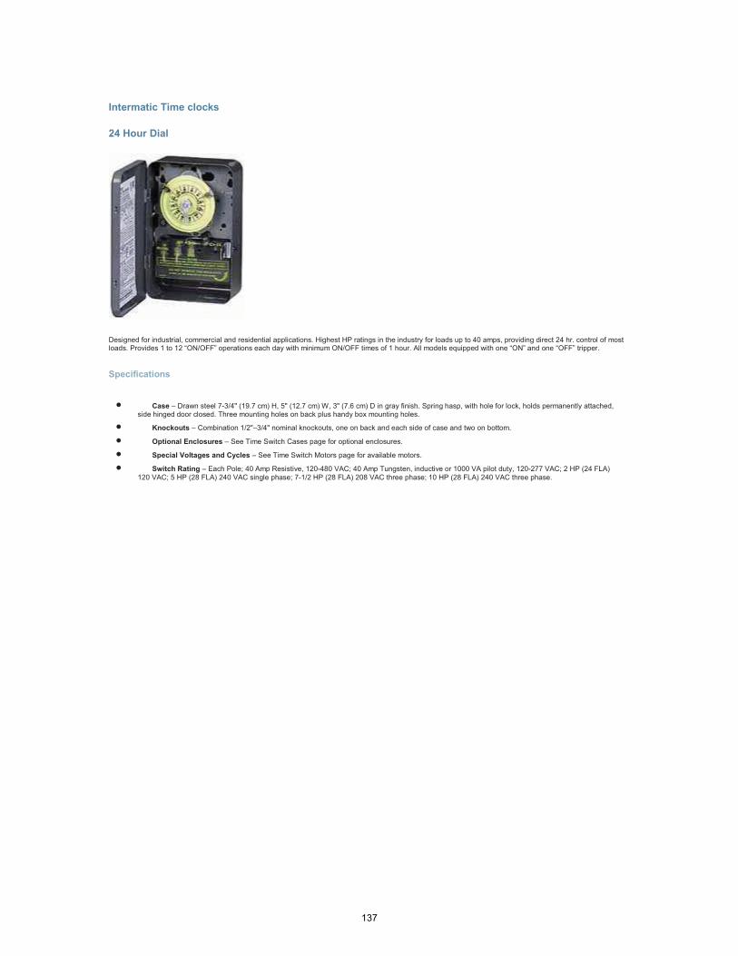
Intermatic Time clocks
24 Hour Dial
Designed for industrial, commercial and residential applications. Highest HP ratings in the industry for loads up to 40 amps, providing direct 24 hr. control of most loads. Provides 1 to 12 “ON/OFF” operations each day with minimum ON/OFF times of 1 hour. All models equipped with one “ON” and one “OFF” tripper.
Specifications
• Case – Drawn steel 7-3/4" (19.7 cm) H, 5" (12.7 cm) W, 3" (7.6 cm) D in gray finish. Spring hasp, with hole for lock, holds permanently attached, side hinged door closed. Three mounting holes on back plus handy box mounting holes.
• Knockouts – Combination 1/2"–3/4" nominal knockouts, one on back and each side of case and two on bottom.
• Optional Enclosures – See Time Switch Cases page for optional enclosures.
• Special Voltages and Cycles – See Time Switch Motors page for available motors.
• Switch Rating – Each Pole; 40 Amp Resistive, 120-480 VAC; 40 Amp Tungsten, inductive or 1000 VA pilot duty, 120-277 VAC; 2 HP (24 FLA)
120 VAC; 5 HP (28 FLA) 240 VAC single phase; 7-1/2 HP (28 FLA) 208 VAC three phase; 10 HP (28 FLA) 240 VAC three phase.
137