NATIONAL DAM INSPECTION PROGRAM. BRIER CREST … · NATIONAL DAM INSPECTION PROGRAM. BRIER CREST...
76
NATIONAL DAM INSPECTION PROGRAM. BRIER CREST Vl00Db DAM. DELAWAR--'ETCIU) FED G0 F FUTCH4(D DACW3-80C-0017 UNCLASSIFIED R -- EhEE,~h
Transcript of NATIONAL DAM INSPECTION PROGRAM. BRIER CREST … · NATIONAL DAM INSPECTION PROGRAM. BRIER CREST...

NATIONAL DAM INSPECTION PROGRAM. BRIER CREST Vl00Db DAM. DELAWAR--'ETCIU)FED G0 F FUTCH4(D DACW3-80C-0017
UNCLASSIFIED R--EhEE,~h

5______ 1 I LAI~
III8
1 .2IL 5 1.4II~ 11111.6
MICROCOPY RESOLUTION TEST CHAR1NATIONAL BUREAU OF STANDARDS-1963-,:

.No
'Ii
Ap -

DELAWARE RIVER BASIN,
TRIBUTARY TO TUNKHANNOCK CREEK, MONROE COUNTY
PENNSYLVANIA
-M~ T.M bM
(NDI ID 4 b.PA -QO879.\-TDER ID 45-245 /
BRIER CREST WOODS, INC. r
p.-
PHASE I INSPECTION REPORT
NATIO6NAL DAM INSPECTION PROGRAM
Prepared by
GANNETT FLEMING CORDDRY AND CARPENTER, INC.Consulting Engineers
P.O. Box 1963Harrisburg, Pennsylvania 17105
Pc~~35'1-C -~i/eIFor
DEPARTMENT OF THE ARMYBaltimore District, Corps of Engineers
Baltimore, Maryland 21203
I FEBReARY 1980

PREFACE
This report is prepared under guidance contained in theRecommended Guidelines for Safety Inspection of Dams,for Phase I Investigations. Copies of these guidelinesmay be obtained from the Office of Chief of Engineers,Washington, D.C. 20314. The purpose of a Phase I inves-tigation is to identify expeditiously those dams whichmay pose hazards to human life or property. The assess-
ment of the general condition of the dam is based uponavailable data and visual inspections. Detailed inves-tigation, and analyses involving topographic mapping,subsurface investigations, testing, and detailed compu-tational evaluations are beyond the scope of a Phase Iinvestigation; however, the investigation is intended toidentify any need for such studies.
In reviewing this report, it should be realized that thereported condition of the dam is based on observationsof field conditions at the time of inspection along withdata available to the inspection team. In cases wherethe reservoir was lowered or drained prior to inspec-tion, such action, while improving the stability andsafety of the dam, removes the normal load on thestructure and may obscure certain conditions which mightotherwise be detectable if inspected under the normaloperating environment of the structure.
It is important to note that the condition of a damdepends on numerous and constantly changing internal andexternal conditions, and is evolutionary in nature. Itwould be incorrect to assume that the present conditionof the dam will continue to represent the condition ofthe dam at some point in the future. Only throughfrequent inspections can unsafe conditions be detectedand only through continued care and maintenance canthese conditions be prevented or corrected.
Phase I inspections are not intended to provide detailedhydrologic and hydraulic analyses. In accordance withthe established Guidelines, the spillway design flood isbased on the estimated "Probable Maximum Flood" for theregion (greatest reasonably possible storm runoff), orfractions thereof. The spillway design flood provides ameasure of relative spillway capacity and serves as anaid in determining the need for more detailed hydrologicand hydraulic studies, considering the size of the dam,its general condition and the downstream damagepotential.
ii

DELAWARE RIVER BASIN
TRIBUTARY TO TUNKHANNOCK CREEK, MONROE COUNTY
PENNSYLVANIA
BRIER CREST WOODS DAM
NDI ID No. PA-00879DER ID No. 45-245
BRIER CREST WOODS, INC.
PHASE I INSPECTION REPORT
NATIONAL DAM INSPECTION PROGRAM
FEBRUARY 1980
* CONTENTS
Description Page
SECTION 1 -Project Information . . . . . . . . . .SECTION 2 -Engineering Data . . . . . . . . . . . 6SECTION 3 -Visual Inspection . . . . . . . ... 8SECTION 4 -Operational Procedures . . . . .... 10SECTION 5 -Hydrology and Hydraulics . . . . . . . 11SECTION 6 -Structural Stability . . . . . . . . . 13SECTION 7 -Assessment, Recommendations, andProposed Remedial Measures .. . .. 15
APPENDICES
Appendix Title
A Checklist - Engineering Data.B Checklist - Visual Inspection.C Photographs.D Hydrology and Hydraulics.E Plates.F Geology.

W I -
PHASE I INSPECTION REPORT
NATIONAL DAM INSPECTION PROGRAM
BRIEF ASSESSMENT OF GENERAL CONDITION
RECOMMENDED ACTION
Name of Dam: Brier Crest Woods DamNDI ID No. PA-00879DER ID No. 45-245
Size: Small (16 feet high; 247 acre-ft)
HazardClassification: Significant
Owner: Brier Crest Woods, Inc.Vincent Marconi, PresidentP.O. Box 1Blakeslee, Pa. 18610
State Located: Pennsylvania
County Located: Monroe
Stream: Tributary to Tunkhannock Creek
Date of Inspection: 14 November 1979
-Based on visual inspection, available records,
calculations, and past operational performance, Brier CrestWoods Dam is judged to be in good condition. The existingspillway will pass the Probable Maximum Flood (PMF), which istwice the Spillway Design Flood (SDF), with 0.2 foot offreeboard. Based on the criteria and the downstreamconditions, the SDF is the 1/2 PMF. If the low areas on thetop of the dam were filled to the design elevation, thefreeboard would increase to 0.5 foot. -The spillway capacityis rated as adequate.
No stability problems were evident for the embankment.The spillway weir meets recommended guidelines forstability.
iii

The ability of the outlet works to function isuncertain.
Maintenance procedures for the dam and appurtenantstructures are inadequate.
The following studies and remedial measures arerecommended to be undertaken by the Owner, in approximateorder of priority, without delay:
(1) Ensure the operational adequacy of the outlet
works, and operate it on a regular basis.
(2) Establish an adequate grass cover on the downstreamslope.
(3) Fill in low areas at the top of the dam.
In addition, the Owner should institute thefollowing operational and maintenance procedures:
(1) Develop a detailed emergency operation andwarning system for Brier Crest Woods Dam.
(2) During periods of unusually heavy rains,provide round-the-clock surveillance of Brier Crest WoodsDam. Have sufficient personnel available to remove debristhat may collect at the spillway bridge.
(3) When warnings of a storm of major proportionsare given by the National Weather Service, the Owner shouldactivate his emergency operation and warning system.
(4) Institute an inspection program such that the
dam is inspected frequently. As presently required by theCommonwealth, the inspection program should include a formalannual inspection by a professional engineer experienced inthe design and contruction of dams. Utilize the inspectionresults to determine if remedial measures are necessary.
(5) Institute a maintenance program so that allfeatures of the dam are properly maintained.
iv
iv ", "'.
...........

BRIER CREST WOODS DAM
[r- Submitted by:
GANNETT PLEMINQ CORDDRYAND) CARPEWTE.R, E NC.
FREDEICK PUTCHKOProject Manager, Dam Section
Date: 21 March 1980
Approved by:
DEPARTMENT OF THE ARMYBALTIMORE DISTRICT,CORPS OF ENGINEERS
)AMES I PECKColonel, Corps of Engineers
NDistrtct Engineer
Date: /0 t=l 7Wi
V

.; 4
I vi

DELAWARE RIVER BASIN
TRIBUTARY TO TUNKHANNOCK CREEK, MONROE COUNTY
PENNSYLVANIA
BRIER CREST WOODS DAM
NDI ID No. PA-00879DER ID No. 45-245
BRIER CREST WOODS, INC.
PHASE I INSPECTION REPORT
NATIONAL DAM INSPECTION PROGRAM
FEBRUARY 1980
SECTION 1
PROJECT INFORMATION
1.1 General.
a. Authority. The Dam Inspection Act, Public Law92-367, authorized the Secretary of the Army, through theCorps of Engineers, to initiate a program of inspection ofdams throughout the United States.
b. Purpose. The purpose of the inspection is todetermine if the dam constitutes a hazard to human life orproperty.
1.2 Description of Project.
a. Dam and Appurtenances. Brier Crest Woods Dam is ahomogeneous earthfill embankment with a toe drain. The dam,including the spillway, is 790 feet long and is 16 feet highat maximum section. The spillway is located near the middleof the dam. It is a concrete gravity weir with a concreteexit channel apron. A reinforced concrete bridge crosses
-- | ... [ I ... -1-

over the spillway. The spillway crest is 25 feet long andis 5.0 feet below the design top elevation of the dam.Vertical walls that retain the embankment act as approachand exit channel walls. The walls also act as bridge
abutments to support the spillway bridge. The underside ofthe bridge is 4.0 feet above the spillway crest. The outletworks consists of a 12-inch diameter corrugated metal pipein the spillway weir with a sluice gate at the upstream end.The gate operating mechanism extends up to the bridgerailing. The various features of the dam are shown on thePhotographs in Appendix C and on the Plates in Appendix E.A description of the geology is included in Appendix F.
b. Location. Brier Crest Woods Dam is located on atributary to Tunkhannock Creek in Tunkhannock Township,Monroe County, Pennsylvania. The dam is approximately 3.7miles southeast of Blakeslee. Brier Crest Woods Dam isshown on the 1973 Photorevision to USGS Quadrangle,Blakeslee, Pennsylvania, at latitude N 410 02' 50" andlongitude W 750 33' 15". A location map is shown on PlateE-1.
c. Size Classification. Small (16 feet high, 247acre-feet).
d. Hazard Classification. Significant hazard.Downstream conditions indicate that a significant hazardclassification is warranted for Brier Crest Woods Dam(Paragraphs 3.le and 5.1c (5)).
e. Ownership. Brier Crest Woods, Inc., VincentMarconi, President, P.O. Box 1, Blakeslee, PA 18610.
f. Purpose of Dam. Recreation.
g. Design and Construction History. Brier CrestWoods Dam was designed by Edward C. Hess Associates, Inc.,Consulting Engineers of Stroudsburg, PA. The preliminarydesign was submitted to the Commonwealth in 1971. TheCommonwealth, apparently suggested some changes to mitigatethe environmental impact. The final design was submitted tothe Commonwealth in April 1972. The Commonwealth issued apermit for construction in June 1972. Construction wasstarted in the summer of 1972 by G. H. Litts and Son, Inc.,Contractors of Marshalls Creek, PA., under the supervisionof Edward C. Hess Associates. The dam was completed inSeptember 1973. Clifford L. Dennis of Edward C. HessAssociates was the project engineer throughout design andconstruction.
-2-

h. Normal Operational Procedure. The pool ismaintained at the spillway crest level with excess inflowdischarging over the spillway. The outlet works is notused. Spillway discharge flows downstream to the confluencewith Tunkhannock Creek.
1.3 Pertinent Data.
a. Drainage Area. (square miles) 0.5
b. Discharge at Damsite. (cfs.)Maximum known flood at damsite Unknown.Outlet works at maximum
pool elevation 15
Spillway capacity atmaximum pool elevation
Design conditions 970Existing conditions 920
c. Elevation. (feet above msl.)Top of dam
Design conditions 1807.0Existing conditions 1806.7
Maximum poolDesign conditions 1807.0Existing conditions 1806.7
Normal pool (spillway crest) 1802.0Upstream invert outlet works 1791.7Downstream invert outlet works 1791.5Streambed at toe of dam 1791.0
d. Reservoir Length. (miles)Normal pool 0.33Maximum pool 0.38
e. Storage. (acre-feet)Normal pool 110Maximum pool (design) 247
f. Reservoir Surface. (acres)Normal pool 26.2Maximum pool (design) 28.5
g. Dam.aHomogeneous
earthfill withtoe drain.
-3-

g. Dam. (cont'd)Length (feet) 790
Height (feet) 16
Topwidth (feet) 44 (changes to30 feetadjacent tospillway)
Side SlopesDesign
Upstream 1V on 2.5HDownstream IV on 2.5H
(slopes flattenadjacent tospillway)
Zoning Earthfill withtoe drain.
Cut-off Cutoff trenchbackfilled withembankmentfill.
Grout Curtain None.
h. Diversion and RegulatingTunnel. None.
i. Spillway.Type Concrete
gravity weir.
Length of Weir (feet) 25.0
Crest Elevation 1802.0
Upstream Channel Reservoir,verticalconcretewalls.
Downstream Channel Concreteapron.
-'4-

j. Regulating Outlets.Type. One 12-inch
diameter
corrugatedmetal pipe.
Length (feet) 13
Closure Sluice gate atintake at up-
stream end.
Access On bridge overspillway.
'4
I .. ... . ... . iiII --1 II L IIml-5 -

SECTION 2
ENGINEERING DATA
2.1 Design.
a. Data Available. Design data available for reviewincluded the following: approved design drawings,specifications, foundation data from test pits, and permitapplication reports.
b. Design Features. The project is described inParagraph 1.2a. The various features of the dam are shownon the Photographs in Appendix C and on Plates E-2 to E-5 inAppendix E. The embankment is shown on Photographs Athrough D. The spillway is shown on Photographs D throughF. The outlet works is shown on Photographs D and E.
c. Design Considerations. Nothing was noted in thereview of the design data that would cause concern. Thespecifications generally reflected good engineeringpractice.
2.2 Construction.
a. Data Available. Construction data available forreview included construction progress reports prepared bythe design engineer and correspondence regardingconstruction. The design engineer verbally amplified theconstruction reports.
b. Construction Considerations. The design engineeramplified the records to explain that some of the embankmentmaterial that was placed during the fall of 1972 came from aswamp in the reservoir area. Consequently, the material wasquite wet and drying the material sufficiently to meetdensity requirements was time consuming. He pointed out,however, that although it was difficult, the Contractor diddry the material sufficiently to compact the fill to therequired density. He stated that no other problems aroseduring construction. The available information indicatesthat the embankment was well constructed.
2.3 Operation. There are no formal records of operation.There have been no formal inspections of the dam since itsconstruction. There are no records of any problems with thedam.
-6-

2.4 Evaluation.
a. Availability. Engineering data were provided bythe Bureau of Dams and Waterway Management, Department ofEnvironmental Resources, Commonwealth of Pennsylvania(PennDER). The Owner made available a representative forinformation during the visual inspection. The designengineer researched his files and provided information atthe request of the inspection team.
b. Adequacy. The type and amount of available designdata and other engineering data are somewhat limited; theassessment is based on the combination of available data,visual inspection, performance history, hydrologicassumptions, and hydraulic assumptions.
c. Validity. There is no reason to question thevalidity of the available data.
-7-

SECTION 3
VISUAL INSPECTION
3.1 Findings.
a. General. The overall appearance of the dam isgood. Some deficiencies were observed as noted below. Asketch of the dam with the locations of deficiencies ispresented on Exhibit B-I in Appendix B. Survey informationacquired for this report is summarized in Appendix B. Onthe day of the inspection, the pool was at spillway crest.Rainfall immediately preceding the inspection resulted invery wet soil conditions.
b. Embankment. The embankment is in good condition.The top of the dam is used as an access road; it is notcovered with vegetation. Vehicular traffic has createdminor depressions, which were full of water on the day ofthe inspection (Photograph A). The upstream slope isprotected by riprap, which is in good condition (PhotographA). The grass on the downstream slope is in poor condition.It is thin and many bare areas exist. Surface runoff haseroded many very shallow rills over most of the downstreamslope (Photograph B). Soil eroded from the embankmentcovers the toe drains, which were not evident during theinspection (Photograph C). A 0.25-gpm flow was observedalong the downstream toe of the dam to the right of thespillway. Its source could not be determined.
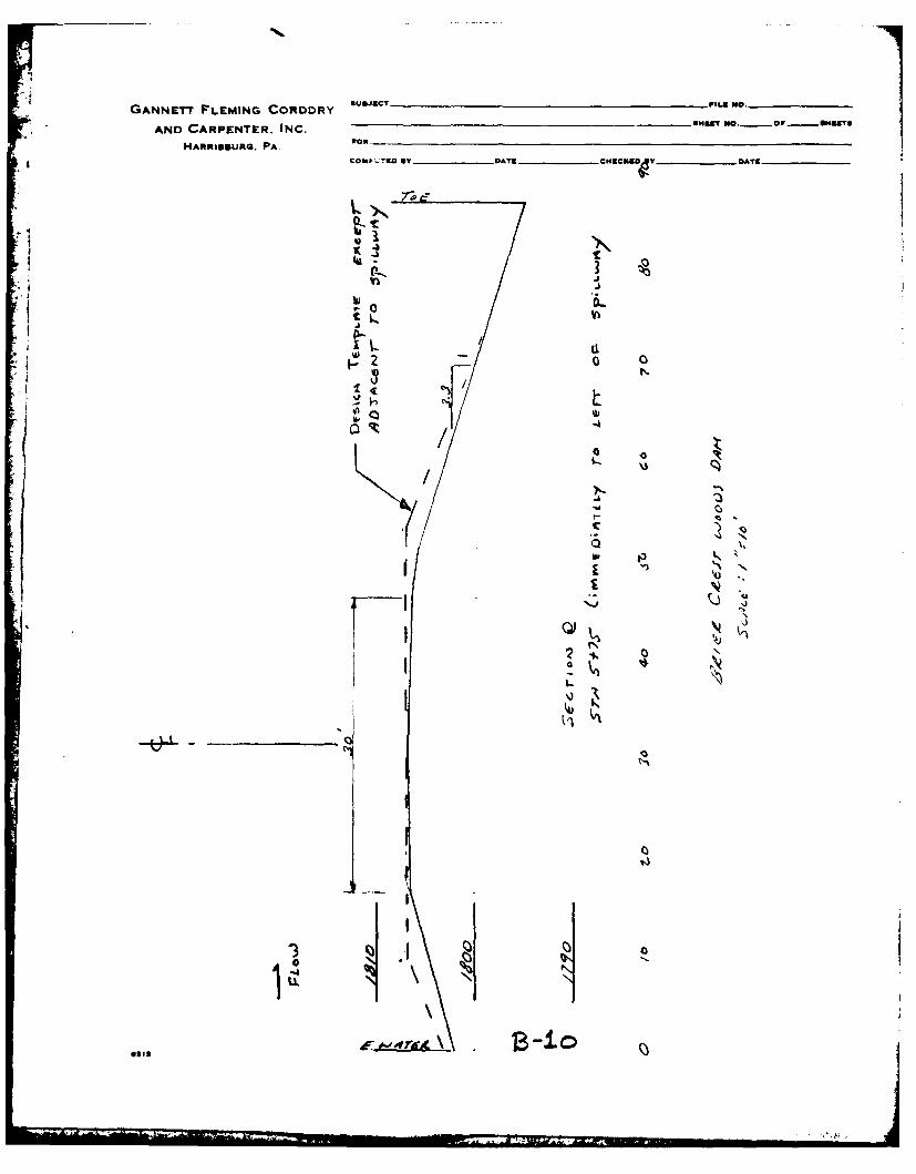
The survey performed for this inspection (AppendixB) reveals that low areas exist on the top of the embankmentto the left of the spillway. The lowest area is 0.3 footbelow design elevation. The survey section shown inAppendix B has flatter slopes and a narrower top width thanthe typical section shown on Plate E-3 in Appendix E.
c. Appurtenant Structures. The spillway is in goodcondition. No deficiencies were observed at either the weiror the exit channel apron. The sidewalls of the exitchannel apron, which also act as the bridge abutments, havea shrinkage crack on each side approximately coincident withthe axis of the dam. The weep holes in these walls weretrickling (Photograph F). The bridge deck is in goodcondition.
-8-

The outlet works is located at the spillway. Itconsists of a corrugated metal pipe extending through theweir with a sluice gate at the upstream end. The pipe isrusty. The Owner's representative could not locate the keyto the padlock that secures the gate operating mechanism tothe bridge railing (Photograph E). He did not recollect thegate ever being operated.
d. Reservoir Area. The watershed is mostly wooded.The only development is minor and is part of the Brier CrestWoods Development. Slopes in the watershed are generallymild.
e. Downstream Conditions. The valley at the damsiteis relatively wide and flat. About 0.2 mile downstream, thevalley narrows and steepens. It then passes below Pa. Route903 in a small culvert. Just beyond Route 903, the streamdrops very rapidly to its confluence with Tunkhannock Creek,which is about 0.4 mile downstream from the dam. Were thedam to fail, damage would probably occur at both a dwellingand a ski shop. Downstream conditions showing the probablelimits of flooding from a dam failure are sketched inAppendix D.
-9-

SECTION 4
OPERATIONAL PROCEDURES
4.1 Procedure. The reservoir is maintained at the spillwaycrest level with excess inflow discharging over the spillwayand into the downstream channel. The outlet works is notused.
4.2 Maintenance of Dam. The Owner's representativereported that maintenance of the dam was infrequent. Healso reported that inspections were infrequent, informal,and not in detail. Apparently, some inspections of the damare being performed as the design engineer was recentlycalled to the site to investigate a minor leak in the sluicegate.
4.3 Maintenance of Operating Facilities. The outlet worksis not maintained.
4.4 Warning Systems in Effect. The Owner's representativestated that he was not aware of any emergency operation andwarning system.
4.5 Evaluation of Operational Adequacy. The maintenance ofthe outlet works is inadequate. Although the embankment andspillway are in good condition, the lack of formalmaintenance procedures could result in eventualdeterioration of the dam. Inspections are necessary todetect hazardous conditions at the dam. An emergencyoperation and warning system is necessary to reduce the riskof dam failure should adverse conditions develop and toprevent loss of life should the dam fail.
-10-

SECTION 5
HYDROLOGY AND HYDRAULICS
5.1 Evaluation of Features.
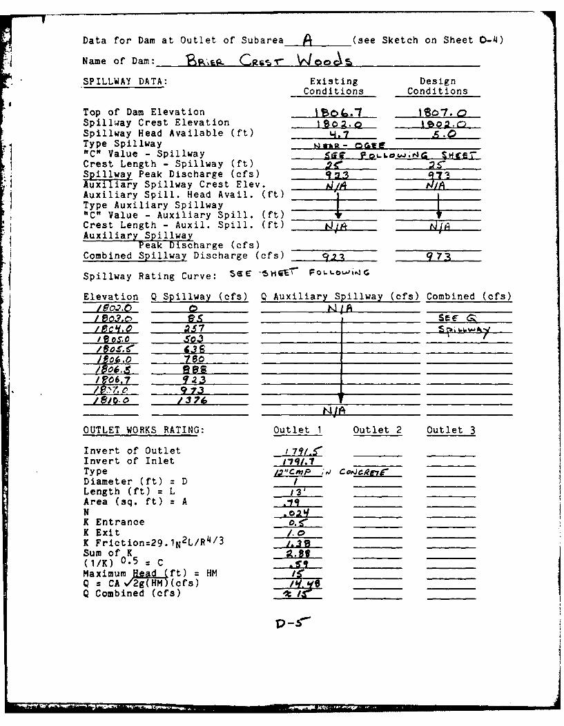
a. Design Data. The available data for the spillwayindicates that the design was based on a Curve "C" dischargeof 720 cfs that was required by the Commonwealth. Thedesign head was 4 feet, with 1 foot of freeboard provided.The underside of the spillway bridge was set at the designhead elevation. The design spillway capacity used in thisReport is 973 cfs, and it was computed using the maximumavailable head of 5.0 feet for design conditions.
b. Experience Data. No records of maximum poollevels are available.
c. Visual Observations.
(1) General. The visual inspection of BrierCrest Woods Dam, which is described in Section 3, resultedin a number of observations relevant to hydrology andhydraulics. These observations are evaluated herein for thevarious features.
(2) Embankment. The low areas on the top of thedam limit the existing spillway capacity to less than themaximum capacity.
(3) Appurtenant Structures. The design elevationof the underside of the spillway bridge is lower than thedesign top of dam elevation, which would cause pressure flowwhen water is near the top of the dam. Discharges underpressure flow would be less than under a free overfallcondition. In computing the existing spillway capacity andin evaluating the spillway adequacy, the effect of the abovecondition was included. There is the potential for thebridge to collect debris during storms. This would reducethe spillway capacity. In computing the existing spillwaycapacity, the effect of debris was not considered.
The ability of the outlet works to functionis uncertain. At present, it cannot be relied upon to drawdown the reservoir.
-11-

(4) Reservoir Area. No conditions were observedin the watershed that might present significant hazard tothe dam.
(5) Downstream Conditions. No conditions wereobserved downstream from the dam that would reduce thehydraulic capacity of the spillway. A failure of the damwould result in a significant discharge along Pa. Route 903.This would probably occur as sheet flow. It would causedamage to a ski shop and to the basement of a dwelling.Loss of life from a failure is possible but unlikely.Downstream from the confluence with Tunkhannock Creek, there
are no structures adjacent to the stream for 2.5 miles. Thedownstream conditions indicate that a significant hazardclassification is warranted for Brier Crest Woods Dam.
d. Overtopping Potential.
(1) Spillway Design Flood. According to thecriteria established by the Office of the Chief of Engineers(OCE), the Spillway Design Flood (SDF) for the size (Small)and hazard potential (Significant) of Brier Crest Woods Damis between the 100-Year Flood and one-half of the ProbableMaximum Flood (PMF). Because of the possibility of loss oflife downstream, the one-half PMF is selected as the SDF forBrier Crest Woods Dam. The watershed was modeled with theHEC-1DB computer program. A description of the model isincluded in Appendix D. The assessment of the dam is basedon existing conditions. The effects of future developmentare not considered.
(2) Summary of Results. Pertinent results aretabulated at the end of Appendix D. The analysis revealsthat Brier Crest Woods Dam can pass the PMF with 0.2 foot offreeboard. If the low areas at the top of the dam werefilled in, the freeboard would increase to 0.5 foot.
(3) Spillway Adequacy. The criteria used to ratethe spillway adequacy of a dam are described in Appendix D.Because the dam can pass the PMF, which is twice the SDF,the spillway capacity is rated as adequate.
-12-

SECTION 6
. i STRUCTURAL STABILITY
6.1 Evaluation of Structural Stability.
a. Visual Observations.
(1) General. The visual inspection of BrierCrest Woods Dam, which is described in Section 3, resultedin a number of observations relevant to structuralstability. These observations are evaluated herein for thevarious features.
(2) Embankment. The depressions caused byvehicular traffic on the top of the dam are of no concern.The erosion on the downstream slope, which was caused bysurface runoff, is not a hazard at present. Long-termneglect could worsen the situation. The design engineerreported that the grass cover at the end of construction wasadequate. The reason for the poor growth of the grass isunknown. The design engineer reported that the toe drainswere constructed as shown on Plate E-3. The soil whichcovers them should not affect their proper functioning. Theflow that was observed along the toe is insignificant. Inall probability it was surface runoff.
The low areas on the top of the embankmentprobably resulted from settlement. The design engineerreported that the template of the section surveyed for thisinspection was approximately the same as the as-constructedtemplate. He reported that the design drawings do notclearly reflect the template near the spillway.
(3) Appurtenant Structures. The shrinkage cracksin the exit channel walls are not a hazard at present; theydo have the potential to eventually start spalling. Theminor flow from the weep holes indicates that they areprobably functioning correctly.
The outlet works operation is assessed inSection 5. The rusty outlet works pipe is of no concern.In essence, the pipe just acts as a form for the surroundingspillway weir concrete.
b. Design and Construction Data. The design engineerreported that no stability analysis was performed for the
-13-

embankment. He also reported that an analysis for thespillway weir was performed but that it could not be locatedin his files.
For this report, the stability of the spillway
weir was checked under the maximum loading condition. Earthpressure and uplift were used in the analysis. For themaximum loading condition, pool level at design top of dam,the resultant was within the middle third of the base. Boththe resistance to sliding and toe pressure were adequate.The stability of the spillway weir meets the criteriaestablished by the Office of the Chief of Engineers (OCE)for stability of gravity structures.
c. Operating Records. There are no formal records ofoperation. According to available data, no stabilityproblems have occurred over the operational history of thedam.
d. Post-construction Changes. There have been nopost-construction changes to Brier Crest Woods Dam.
e. Seismic Stability. Brier Crest Woods Dam islocated in Seismic Zone 1. Earthquake loadings are notconsidered to be significant for small dams located in Zone1 when there are no readily apparent stability problems. Asthere are no readily apparent stability problems, theability of the dam to withstand an earthquake is assumed tobe adequate.

SECTION 7
ASSESSMENT, RECOMMENDATIONS, AND REMEDIAL MEASURES
7.1 Dam Assessment.
a. Safety.
(1) Based on available records, visualinspection, calculations, and past operational performance,Brier Crest Woods Dam is judged to be in good condition.Based on existing conditions, the spillway will pass the PMFwhich is twice the Spillway Design Flood (SDF), with 0.2foot of freeboard. Based on the criteria and the downstreamconditions, the SDF is the 1/2 PMF. If the low areas on thetop of the dam were filled to the design elevation, thefreeboard would increase to 0.5 foot. The spillway capacityis rated as adequate.
(2) No stability problems were evident for theembankment.
(3) The spillway weir meets OCE guidelines forstability under the maximum operating condition.
(4) The ability of the outlet works to functionis uncertain.
(5) Maintenance procedures for the dam andappurtenant structures are inadequate.
(6) A summary of the features and observeddeficiencies is listed below:
Feature and Location Observed Deficiency
Embankment: Low areas at top; minorerosion of downstream slope;poor vegetation on downstreamslope.
Spillway: Shrinkage cracks in exitchannel sidewalls.
Outlet Works: Uncertain operation.
-15-

b. Adequacy of Information. The informationavailable is such that an assessment of the condition of thedam can be inferred from the combination of visualinspection, past performance, and computations performedprior to and as part of this study.
c. Urgency. The recommendations in Paragraph 7.2should be implemented without delay.
d. Necessity for Further Investigations. Accomplish-ment of remedial measures will not require further investi-gations by the Owner.
7.2 Recommendations and Remedial Measures.
a. The following studies and remedial measures arerecommended to be undertaken by the Owner, in approximateorder of priority, without delay:
(1) Ensure the operational adequacy of the outletworks. soe
(2) Establish an adequate grass cover on thedownstream slope.
(3) Fill in low areas at the top of the dam.
b. In addition, the Owner should institute thefollowing operational and maintenance procedures:
(1) Develop a detailed emergency operation andwarning system for Brier Crest Woods Dam.
(2) During periods of unusually heavy rains,provide round-the-clock surveillance of Brier Crest WoodsDam. Have sufficient personnel available to remove debristhat may collect at the spillway bridge.
(3) When warnings of a storm of major proportionsare given by the National Weather Service, the Owner shouldactivate his emergency operation and warning system.
(4) Institute an inspection program such that thedam is inspected frequently. As presently required by theCommonwealth, the inspection program should include a formalannual inspection by a professional engineer experienced inthe design and construction of dams. Utilize the inspectionresults to determine if remedial measures are necessary.
(5) Institute a maintenance program so that allfeatures of the dam are properly maintained.
-16-

APPENDIX A
CHECKLIST ENGINEERING DATA

'41
X
. ID
49.'
00F
kz
000
0 '
-. Ni
........ .~
-.- .-

ci ~JJ~44
4..4
-4~
I- 'I
0
22
cc 0(0 cc2
00w- /

04
4.)
CO7
000. co
o~ to
R 2a

-1
pis.'
* 0
~ue~
A
* S4
:1- 2~~Ii ifl
wI-'C
'3; 2'7 Ii0 '2z
IU
44 9
f-i
Co
f-iU
40 Co 0
U- U
4 ~.,
>4 ~0 In Co 0- 00-a
Co 0
,~-I0f

APPENDIX B
CHECKLIST VISUAL INSPECTION

IL
. J
2E,
0 NP-4 I
LLjL
-4 -4 &L
0
0
-%4
*. 0
Zo so 23 lA
00

CZ%
0
ZL 0 .
2'~ A
0 0
6 gAu '90zg ' k!
.5 ~ J'

00
0 U
0i w
dCC
Z 4)
0 ~
dC

0
It tE
o NI
0
0 109 Z
~0
ocj~ o V
12-6. 1
U80Z5t

z
z
III a 4
>4 '
0
Ci~vi
GO 0w
00
2t 4
00
0.0
20z0 *-4
U l
0 4 *~77ZU1

0u
E-4R
~ 00

5-4-
0 10
I
'3 '"t> v4L)q
1wz
Gol
0 0

GA
z
0
9-3
444
Co O

GANNETT FLEMING CORDDRY _ ___CT N____o.
AND CARPENTER. INC.
HARRISBURG. PA. FOR
"Qg 7dF CONPUTED UT - T VIV my DAYS
-e I
146074'
J
00a,
I .4306.9 * .
I -,wI
____ ___ ____.'J7.4
______ ______ ______ ____________ tj'b
GANNETTF FLEMING CORDDRY usy
AND CARPENTER. INC.- M @...0A51
HARRISBURG. PA.wo
7- -
0
-OIL
j 0
LLL

.1i
LOW AREAS
RESERVOIR POOR VEGETATION AND SHALLOW(AT SPILLWAY CREST SWALES ERODED IN SURFACEON DAY OF INSPECTION)
OUTLET WORKS-- SHRINKAGE CRACKS
OWNER UNABLETO FIND KEY TOUNLOCK OPERATORPADLOCK 1 GPM FLOW
POOR VEGETATION AND SHALLOWSWALES ERODED IN SURFACE
NOTE:
SEE SURVEY DATA AND TEXTFOR SLOPES AND TOP WIDTH
PHASE I INSPECTION REPORT
NATIONAL DAM INSPECTION PROGRAM
BRIER CREST WOODS DAM
NOT TO SCALE BRIER CREST WOODS, INC.
RESULTS OFVISUAL INSPECTION
FEBRUARY 1980 EXHIBIT B-I

APPENDIX C
PHOTOGRAPHS

A. Upstream Slope
B. Downstream Slope
C-1

N, l1 OD \
C. Downstream Slope
1). Sp-I'lway Bridge
C-2

BR[EH CHEST WOODS DAM
E. spillway Approach
F. Spillway
C-3

RESERVOIR
OUTLET WORKS - ......
-LOCATION AND ORIENTATION OF CAMERAA PHOTOGRAPH IDENTIFICATION LETTER
PHASE I INSPECTION4 REPORTNATIONAL DAM INSPECTION PROGRAM
BRIER CREST WOODS DAMNOT TO SCALE B3RIER CREST WOODS, INC.
FEBRUARY 1980 EXHIBIT C-I

APPENDIX D
HYDROLOGY AND HYDRAULICS

APPENDIX 0
HYDROLOGY AND HYDRAULICS
Spillway Capacity Rating:
In the recommended Guidelines for Safety Inspectionof Dams, the Department of the Army, Office of the Chiefof Engineers (OCE), established criteria for rating thecapacity of spillways. The recommended Spillway DesignFlood (SDF) for the size (small, intermediate, or large)and hazard potential (low, significant, or high) class-ification of a dam is selected in accordance with thecriteria. The SDF for those dams in the high hazardcategory varies between one-half of the Probable MaximumFlood (PMF) and the PMF. If the dam and spillway arenot capable of passing the SDF without overtoppingfailure, the spillway capacity is rated as inadequate.If the dam and spillway are capable of passing one-halfof the PMF without overtopping failure, or if the dam isnot in the high hazard category, the spillway capacityis not rated as seriously inadequate. A spillwaycapacity is rated as seriously inadequate if all of thefollowing conditions exist:
(a) There is a high hazard to loss of life fromlarge flows downstream of the dam.
(b) Dam failure resulting from overtopping wouldsignificantly increase the hazard to loss of life down-stream from the dam from that which would exist justbefore overtopping failure.
(c) The dam and spillway are not capable ofpassing one-half of the PMF without overtoppingfailure.
Description of Model:
If the Owner has not developed a PMF for the dam,the watershed is modeled with the HEC-1DB computerprogram, which was developed by the U.S. Army Corps ofEngineers. The HEC-iDB computer program calculates aPMF runoff hydrograph (and percentages thereof) androutes the flows through both reservoirs and streamsections. In addition, it has the capability tosimulate an overtopping dam failure. By modifying therainfall criteria, it is also possible to model the 100-year flood with the program.
D-1
A'

APPENDIX P
DEL A JA C River BasinName of Stream: 7" . TO o ,,,jM . ,'j"r C&EE-IName of' Dam: 'iiiNDI ID No.: PA - Oa979DER ID No.: iy"-aVj"
Latitude: R t6_,2r. sb" Longitude: -1 " 33e IS"Top of Dam Elevation: l4o7. p I(b0Streambed Elevation: l'j Height of Dam: I ftReservoir Storage at Top of-Dam Elevation: acre-ftSize Category: Sr .Hazard Category: -Sp& Lr.jI (see Section 5)Spillway Design Flood: /AA.E', loo-y. T .r-
UPSTREAM DAMS
Distance Storagefrom at top ofDam Height Dam Elevation
Name (miles) (ft) (acre-ft) Remarks
DOWNSTREAM DAMS
D-2

I1DELAW.tJA River Basin
Name of Stream: Tg' c To T Aas- Cw.Name of Dam:
Amo CULe_
DETERMINATION OF PMF RAINFALL & UNIT HYDROGRAPHUNIT HYDROGRAPH DATA .
DrainageSub- Area Cp Ct L Lia iL' Tp Map Platearea (square ] C miles miles miles hours Area
miles) (1) (2) (3) (14) (5) (6) (7) (8)
A 0 e 0- 210_ _ J 110
TotaT 0 ( TSee Sketch on Sheet 0-14)(1) & (2): Snyder Unit Hydrograph coefficients supplied by
Baltimore District, Corps of Engineers on maps andplates referenced in (7) & (8)
The following are measured from the outlet of the subarea:(3): Length of main watercourse extended to divide(4): Length of main watercourse to the centroidThe following is measured from the upstream end of thereservoir at normal pool:(5): Length of main watercourse extended to divide(6): Tp=Ct x (L x Lca) 0.3, except where the centroid ofthe subarea is ocated in the reservoir. ThenTp=Ct x (L') 0.0
Initial flow is assumed at 1.5 cfs/sq. mileComputer Data: QRCSN = -0.05 (5% of peak flow)
RTIOR = 2.0RAINFALL DATA:
PMF Rainfall Index= ;2._ in., 24 hr., 200 sq. mile.Hydromet. 40 Hydromet. 33
(Susquehanna Basin) (Other Basins)Zone: N/A __
Geographic AdjustmentFactor: 1.0
Revised IndexRainfall: r4 i A
RAINFALL DISTRIBUTION (percent)Time Percent
_ 6 hours -12 hours24 hours48 hours72 hours
96 hours
D-3

GANNETT FLEMING CORODRY $*~jKC1 PILS No.
AND CARPENTER. INC. S"S9T no. oF- o"K r,
HARRIOURG, PA..S, ¢COMPUTED my'_. AT , g*gge C EK ow__r__.,
/A
D--f
-- E. . .... - I
I_ , . VA CC103
\nCchl~.e
o' C 0 ortopi
T~L~ -saKV P Ac j ..e. ........ ...... ..g .... ........ .......
Data for Dam at Outlet of Subarea A (see Sketch on Sheet 0-4)
Name of Dam: R,, ,- Cery - Wooc
SPILLWAY DATA: Existing DesignConditions Conditions
Top of Dam Elevation ____._ _ 187. 0Spillway Crest Elevation ISo2.o _ __S ._Spillway Head Available (ft) _S, 7 g.CType Spillway I - wE"C" Value - Spillway <r , Se-Crest Length - Spillway (ft) 2r_,,_ _ $-_,,Spillway Peak Discharge (cfs) _ ______
Auxiliary Spillway Crest Elev. _____1A
Auxiliary Spill. Head Avail. (ft)Type Auxiliary Spillway"C" Value - Auxiliary Spill. (ft) TCrest Length - Auxil. Spill. (ft) ZAuxiliary Spillway
Peak Discharge (cfs)Combined Spillway Discharge (cfs) _ --A 973
Spillway Rating Curve: Se -5vGHQr Fouov 4G
Elevation Q Spillway (cfs) Q Auxiliary Spillway (cfs) Combined (cfs)19.2.0' 0______ ______A
I ¢ .057 _ _2S7
/60 S.C .. O39!,eos, 5.3 ______ ______
/2 06.0 780 _ _ _ _ _ _ _ _ _ _ _ _ _ _ _ _ _
1806.5 _ .ass__F~06.7 __ _ _ _ _ __ _ _ _ _ _ _ _ _ _ _ _
_____1 __e 973_ _ _ _ _ _
_______ 1376__ _ _ _ _ _ _ _ _ _ _ _ _ _ _ _
OUTLET WORKS RATING: Outlet 1 Outlet 2 Outlet3
Invert of Outlet 7 ____ ____
Invert of Inlet r1'.7Type Iy'cnp ,, Coigr__"Diameter (ft) =DLength (ft) = L 13'Area (sq. ft) = A _ _q
N - o_K Entrance _._ _
K ExitK Friction:29.1N2 L/R 4 / 3 __3Sum of K 9..,Lt.(1/K) 0.5 z C --C_ _
Maximum Head (ft) = HM __
Q = CA c/2g(HM)(efs) _____
Q Combined (cfs) ____,___
p -.

4Li GANNErT FLEMING CORDORY SDJCT , 0._ ___
AND CARPENTER. INC. SMET [email protected] METs
HA tr t EUuRG. PA. Pon
COMPUTED BY _____ _byDATE CE EU DYTE
W~SL- L~#% TC30 = 14-/Ima+ +" F;r- 7'3
*i C "- 3 1 "C.I H +I+, ,
W 1A C L0 a&zH-D4o; 3,;z 8 o.r
/ 3.0L 85
S3.4 7 /6o9.o4 3.77, 319 I ov. 5-
3 3. ? 503
131
4- L-0 13 14a.r. IS Z.
Ok'Fet VA I~c ~q~oJ A: PS-/cZ QC. 7,. /0 0 K
/g , ,,,oo seele 06. "7 IF. 3
[807.0 973
D-c(
gls

Data for Dam at Outlet of Subarea _(See sketch on Sheet D-4)
Name of Dam: "9','Ea. CRe.- 6 ) oot
STORAGE DATA:
StorageArea million
Elevation (acres) gals acre-ft Remarks
_/78q.t =ELEVO* 0 0 0jqZ =ELEVI .; 1 33 It =OS1 DER -A.0cLI
.,. 8o7,0__ ______I A .o _ __ "
* ELEVO = ELEVI - (3SI/Aj)* Planimetered contour at least 10 feet above top of dam
Reservoir Area at Normal Pool is percent of subareawatershed.
BREACH DATA: N Use.
See Appendix B for sections and existing profile of the dam.
Soil Type from Visual Inspection:
Maximum Permissible Velocity (Plate 28, EM 1110-2-1601) fps(from Q = CLH3/ 2 = V.A and depth = (2/3) x H) & A = L-depth
HMAX = (4/9 V2 /C2 ) = ft., C = Top of Dam El.=
HMAX + Top of Dam El. = _ FAILEL(Above is elevation at which failure would start)
Dam Breach Data:
BRWID = ft (width of bottom of breach)Z = (side slopes of breach)
ELBM : (bottom of breach elevation, minimum ofzero storage elevation)
WSEL = (normal pool elevation)T FAIL= mins = hrs (time for breach to
develop)
p-7

GANN6TT FLEMING CORDORY suEJEC? VILS 00.______
AND CARPENTER. INC.N. V...3E?
HARN188UNG. PA. a
ML)L.TI.. BY~ -OATChCK 5'
or- 'PEAi. FL-wb 7D-c
as10

Ccc~c PM 3*
j, I
o do
ata
ccJ
N1w NC tv*
w ~Ow
a M M sC .M .
a-0a -FO*AD woo
00a1.1N N fm ty

z z
A0 0 4 ,
0'o am
z t 05 0 P,
um0 04.
Ill -00
a..on 0 b. N
00h0 I
00 44bE 4
0atl~L~l~ - e
W~ll NO * *o

ccag.c05 2 00
-a C,
'K 0
on PM m~o
*P~flh C
0
0000000
li C. .C
S.,,
a ww w
~~N~ ol0 0aoir

GANNETT FLEMING CORDRY FILE MO.
AND CARPENTER. INC.mAlRoissuRe. PA.
compuTED ST DATE CHECKE y UT 0*1
Pf A A;P4FA&.L 4 7 i
QrvLow Ic~ OHe7'sIa1
OFLOW~ C-S) S .H0z
FREC'OA-La12 I

LIMITS OF ADDITIONALDOWNSTREAM FLOODINGNOT SHOWN
-,----PA. ROUTE 903
APPROXIMATE MINIMUM LIMITS OFDOWNSTREAM FLOODING SHOULDDAM FAILURE OCCUR
BRIER CREST
WOODS DAM
NOTES:I. LIMITS OF DOWNSTREAM FLOODING ARE
ESTIMATES BASED ON VISUALOBSERVATIONS. THIS MAP SHOULD NOTBE USED IN CONNECTION WITH THE PHASE I INSPECTION REPORTEMERGENCY OPERATION AND WARNING NATIONAL DAM INSPECTION PROGRAIPLAN. BRIER CREST W)OOS DAM
2. CIRCLED NUMBERS INDICATE STATIONSUSED IN COMPUTER ANALYSIS. BRIER CREST WO0K IM
2000 0 2000 DOWNSTREAM1 DEVELOPMENT PLAN
SCALE: I IN. =2000 FT. F'BRUARY I9O EXHiBIT D-I

-I
APPENDIX E
PLATES

PA. ROUTE 115TUNKHANNOCK /
CREEK
PA. ROUTE 903\
WOODS DAM
PHASE I INSPECTION REPORTNATIONAL DAM INSPECTION PROGRAM
BRIER CREST WOODS DAMBRIER CREST WOODS, INC.
2000 0 2000 LOCATION MAPSCALE: I IN. :2000 FT. FEBRUARY 960 PLATE E-1

reCT er rkcSCT: Aldo AT- r..4
ffN I
G~tj ALELN!lop-

lo W4 j I -
S , . ,kcc,
7'.. $CC.C
I-4
'./
Zflj
//
PHASE I INSPECTION REPORT
NATIONAL DAM INSPECTION PROGRAMP,.,f, DAM BRIER CREST WOODS DAM
.rE, ,^Ze# CRS.-, m , cA. ,,OO ,S BRIER CREST WOODS, INC.= ! JIJ4O 4 I$I"1 jeA r AS D b4DI
ala.-~.s,. . GENERAL PLAN. - . ... v 1 }, FEBRUARY 1980 PLATE E-2
I I n Dl a
, __ . .. ..
-..,

..- !±r P-.4. r. v, -r. e-
W! L.T .1 V k'(I , -O(!R.~jr PROFILE OF DA" S ITE7
e. t...
- ~ a --- - I ,- S
P~3=5. re-.
E LEL-I T' I
__ 4

III-. 3CALL ... ... .. .6
1---. w . -w>
fj-" '- H ix C-;. i- zs ; .- - _AP , 7'
12,k~tk7Kr2§..L.K-1 .A N -7
- LC) ... t r~;DPA.fl2 T OF :; .OL-t5
.. ..~ .. + ,r r- to '-'
.h , : ,.. .
- PHASE I INSPECTION REPORTNATIONAL DAM INSPECTION PROGRAM
i r- BRIER CREST WOODS DAM.. LI( - CT-EST ac. COP BRIER CREST WOODS, INC.
;Uj ,,-'XcC T1 .I - L CC "
iL JUU 4. t-1 "- .-- PROFILE AND SECTION
FEBRUARY 1980 PLATE E-3

.VL. C*SJTAIA.iS -Q XOu( .6 3.
FLA"I SAGA-t- Lb OPI-jN
------
W.EEP H-WLE IN-. WIALL- DETAIL
4 Z~

± I Os. f *'I
F4 -;P a
* . _4 * .r .-- ,,-.
-' , 2 - .4 - T
.6 Q M - 5-
AtA
f,*T 24V j^?e 4 CI , L f4$
W"- 111- 1" aox NATIONAL DAM INSPECTION PROGRAM
... .. .,. § _ ,, '.4. .
.- .. . ... ... ,::.,.,, ,.,:,.D... . BRIEIR CREST W OODS DAM. .... .. | ' I .; , ' ' ' ' ~ l ,RER C E57 Wo,' - CORP BRIER CREST WOODS, INC.
v PAl SPILLWAY
"FEBRUARY 1980 PLATE E-4
-- 1 i* UfrET-5C"O'

71 ~
f ~ r t I&.4...A

t _F
t" tV
0. * I '.
,0 , , .. A ." 0. -
11/1,4 1.4L '*P SE TIf
L" A.1I4 , F
.' 88
*' }:
rl~
B 4C ,JV- I rO
- ~ ~ ~ VM WALL~ IV'A.. -TYP 50LOA
N. PHS ISETONRPR
NATIONAL DAM INSPECTION PROGRAM,,...pBo B.tM BRIER CREST WOODS DAM
k-' ,SI'ER CRES"T WOODS CO.RP BRIER CREST WOODS, INC.
A U .4 ' ,o. a. ,w4,.., SPILLWAY DETAILS
.V, -. ... ,,9" .. F B A 18L T
FERUR 190PAT -

APPENDIX F
GEOLOGY

BRIER CREST WOODS DAM
APPENDIX F
GEOLOGY
Brier Crest Woods Dam is located in Monroe County withinthe Appalachian Plateau Province. The most pronouncedtopographic feature in the area is Camelback Mountain, whichis a part of the Pocono Plateau Escarpment. The escarpmenthas a well-defined southwestward trend from CamelbackMountain, but is more irregular between Camelback and Mt.Pocono, which lies to the north. Streams east of theescarpment drain directly to the Delaware River, while thoseto the west drain to the Lehigh River.
The Pocono Plateau Section lies to the west of theescarpment. This area is relatively flat, with local reliefseldom exceeding 100 feet. The topography has been greatlyinfluenced by continental glaciation. Many features werecreated by deposition of glacial materials. The entireplateau lacks well-developed drainage.
East of the escarpment is the Glaciated Low PlateausSection of the province. This area is characterized bypre-glacial erosional topography with locally-thick glacialdeposits. Local relief is generally 100 to 300 feet.
Bedrock units of the sections described above are thelithified sediments of offshore marine, marginal marine,deltaic and fluvial environments associated with the DevonianPeriod. These units include siltstones of the MahantangoFormation, siltstones and shales of the Trimmers RockFormation, and seven mapped members of the CatskillFormation. These members include sandstones, siltstones, andshales of the Towamensing Member; sandstone, siltstone andshale of the Walcksville member; sandstones, siltstones andshale of the Beaverdam Run Member; sandstone and shale in theLong Run Member; sandstones and conglomerates in thePackerton Member; sandstones and some conglomerates in thePoplar Gap Member; and sandstones and conglomerates in theDuncannon Member.
Brier Crest Woods Dam is underlain by the Poplar GapMember of the Catskill Formation. The Poplar Gap Member ispredominantly a gray sandstone and conglomeratic sandstonewith interbedded siltstones and shales. Sandstones present
F-i
L ,i,.l, I

are thick-bedded, fine-to coarse-grained and exhibit very lowprimary porosity due to a clay and silica matrix. Effectiveporosity results from fractures and parting planes.Conglomeratic sandstone occurs primarily as concentrates ofsub-round to round quartz pebbles. The siltstones and shalesat the site are thin-bedded and also have low porosity.
The rocks are well-indurated and generally are notsusceptible to slope failure; however, the presence ofwell-developed bedding and joint planes will result in somerockfall from vertical and high-angle cut slopes.
Bedrock is entirely overlain by glacial till of LateWisconsin Age. This till is an unsorted mixture of clay,silt, sand, and gravel. It is moderately cohesive and is
derived locally from the sandstones of the CatskillFormation. Thickness of the till varies from 5 to 75 feet.
The dam is founded on this till.
F-2

w I
,1 ~ '1 I
~I~W~III a3
ri 1~3 a-i~I~ '
x"' 'cI
IL
,.-., ~~ ~ 13IE CRE00ST20 ~GOLGC ASCL N:200F.FBURu18 XIIi-