National Crane Series NBT50 - BiggeNational Crane Series NBT50 Preliminary Product Guide Features...
12
National Crane Series NBT50 Preliminary Product Guide Features • 31,1 m (102 ft) four-section full power boom and optional 39,01 m (128 ft) five-section full power boom • 45,36 t (50 USt) at 2,44 (8 ft) and 49,90 t (55 USt) at 2,44 (8 ft) rating • Self-lubricating Easy Glide wear pads • Tailswing counterweight • Outrigger design eliminates need for SFO
Transcript of National Crane Series NBT50 - BiggeNational Crane Series NBT50 Preliminary Product Guide Features...

National Crane Series NBT50 Preliminary Product Guide
Features
• 31,1 m (102 ft) four-section full power boom and optional 39,01 m (128 ft) five-section full power boom
• 45,36 t (50 USt) at 2,44 (8 ft) and 49,90 t (55 USt) at 2,44 (8 ft) rating
• Self-lubricating Easy Glide wear pads
• Tailswing counterweight
• Outrigger design eliminates need for SFO

Features
Four or five-section boomA four-section 31,1 m (102 ft) boom comes standard and can be equipped with a 7,9 m (26 ft) or a 13,7 m (45 ft jib). The NBT50 Series also offers a five-section (39,01 m) 128 ft optional boom which can be equipped with either a 7,9 m (26 ft) or a 13,7 m (45 ft) jib for additional lifting versatility.
OutriggersEquipped with both sides of sub frame and in-cab outrigger controls. The NBT50 Series outriggers allow quick and easy crane set-up and includes a new outrigger beam position sensing system that aids the operator in selecting the right load chart based on the crane’s outrigger footprint. The new front outrigger box has a new X-shaped footprint that eliminates the need for a single front outrigger.
Dimensions:Full spanFront: 7,09 m (23 ft 3 in)Rear: 7,39 m (24 ft 3 in)
Mid spanFront: 4,72 m (15 ft 6 in)Rear: 4,90 m (16 ft 1 in)
Retracted-front and rear2,39 m(7 ft 10 in)
Deluxe operator’s cabThe Series NBT50 operator’s cab includes all-steel construction with acoustical lining and tinted glass throughout, air conditioning, deluxe seat with arm rest mounted single-axis electric controllers, windshield and sliding skylight with electric wipers, diesel heater with defroster, circulating fan, fire extinguisher, and dual cab mounted work lights.
Overload protectionAll National Crane boom trucks are equipped with
overload protection. A Load Moment Indicator (LMI) is
standard on all NBT50 Series machines. The LCD color
display is visible in full or low light and displays all crane load
lifting values simultaneously. The LMI includes Work Area Definition System (WADS).
National Crane Series NBT50• 45,36 t (50 USt) maximum capacity• 42,10 m (138 ft) maximum tip height (main boom)• 55,78 m (183 ft) maximum tip height (boom with jib)
National Crane NBT55• 49,90 t (55 USt) maximum capacity• 42,10 m (138 ft) maximum tip height (main boom)• 55,78 m (183 ft) maximum tip height (boom with jib)

Features
National Crane is proud to introduce the Series NBT50 craneThe Series NBT50 represents the pinnacle of machine performance, combining the latest in both hydraulic and electronic machine control. This new product provides premium operator comfort with the latest Manitowoc cab design, simplified machine setup with no need for an SFO and front bumper control of the hoist(s).
• The cable follower will alert operators when the last of the wire rope is being used and the Drum Rotation Indicator will keep constant tension on the rope reducing the potential for bundling.
• Speedy-reeve boom tip and sheave blocks simplify rigging changes by decreasing the time needed to change line reeving.
• Easy Glide boom wear pads reduce the conditions that cause boom chatter and vibration. The net result is smoother crane operation.
• Pressure compensated, load sensing hydraulic system
- PTO mounted axial piston pump
- Superstructure mounted reservoir with integral suction valve/filter, return filter, sight gauge, and temperature gauge
- Oil cooler with 16 inch fan and integral bypass block with temperature sensor
- Pressure transducers integral to the lift cylinder holding valve.
• LMI system features a 7 in graphical, color display. Real-time crane information is displayed with numerous operator features such as soft metric load chart conversion, hydraulic filter change reminders and an electronic hour meter.
• Both single and dual axis controls are options for superior operator comfort, along with optional AC, a diesel heater and ergonomic seats.
4
Contents
Specifications 5
Capacities 7
Dimensions 10
Accessories 11

5Series NBT50
Specifications
Boom and jib combinations data
Note: Maximum tip is measured with outriggers/stabilizers fully extended.
Available in two basic models:
NBT 50 - 102: Equipped with a 9,55 m - 31,1 m (31.3 ft - 102 ft) four-section boom. This model can be equipped with an optional 7,9 m (26 ft) fixed offsettable jib, offering a vertical reach of 39,01 m (134 ft) and a 7,9 m - 13,7 m (26 ft- 45 ft) jib, providing a vertical reach of 44,80 m (153 ft).
9,5 m - 31,1 m (31.3 ft - 102 ft) four-section full power boom FJ-OS 7,9 m (26 ft) fixed offsettable at 0° and 30° manual jib
9,55 m - 31,1 m (31.3 ft - 102 ft) four-section boom FJM-OS 7,9 m - 13.7 m (26 ft - 45 ft) two-section offsettable at 0° and 30° manual jib
NBT50-128: Equipped with a 9,7 m - 39,01 m (32 ft - 128 ft) five-section boom. This model can be equipped with an optional 7,9 m (26 ft) fixed offsettable jib offering a vertical reach of 46,9 m (160 ft) and a 7,9 m - 13,7 m (26 ft - 45 ft) two-section offsettable jib, providing a vertical reach of 52,7 m (179 ft)
9,7 m - 39,01 m (32 ft - 128 ft) five-section full-power boom FJ-OS 7,9 m (26 ft) fixed offsettable at 0° and 30°
9,7 m - 39,01 m (32 ft - 128 ft) five-section full power boom FJM-0S 7,9 m - 13,7 m (26 ft - 45 ft) two-section offsettable 0° and 30° manual jib
6
Specifications
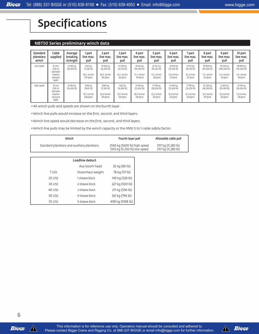
NBT50 Series preliminary winch data
Standard planetary
winch
Cable supplied
Average breaking strength
1 part line max.
pull
2 part line max.
pull
3 part line max.
pull
4 part line max.
pull
5 part line max.
pull
6 part line max.
pull
7 part line max.
pull
8 part line max.
pull
9 part line max.
pull
10 part line max.
pull
Low speed 16 mm(5/8 in)
diameter rotation resistant
IWRC
25 583 kg (56,400 lb)
5103 kg (11,250 lb)
58,2 m/min (191 fpm)
10 206 kg (22,500 lb)
28,9 m/min (95 fpm)
15 309 kg (33,750 lb)
14,2 m/min (63 fpm)
20 412 kg (45,000 lb)
17,3 m/min (47 fpm)
25 515 kg (56,250 lb)
11,6 m/min (38 fpm)
30 618 kg (67,500 lb)
9,4 m/min (31 fpm)
35 721 kg (78,750 lb)
8,2 m/min (27 fpm)
40 824 kg (90,000 lb)
7,0 m/min (23 fpm)
45 359 kg (100,000 lb)
6,4 m/min (21 fpm)
48 895 kg (110,000 lb)
5,8 m/min (19 fpm)
High speed 16 mm(5/8 in)
diameter rotation resistant
IWRC
25 583 kg (56,400 lb)
2540 kg (5600 lb)
116,7 m/min (383 fpm)
5080 kg (11,200 lb)
58,2 m/min (191 fpm)
7620 kg (16,800 lb)
38,7 m/min (127 fpm)
10 160 kg (22,400 lb)
28,9 m/min (95 fpm)
12 700 kg (28,000 lb)
23,2 m/min (76 fpm)
15 240 kg (33,600 lb)
19,2 m/min (63 fpm)
17 780 kg (39,200 lb)
16,5 m/min (54 fpm)
20 320 kg (48,000 lb)
14,3 m/min (47 fpm)
22 861 kg (50,400 lb)
12,8 m/min (42 fpm)
25 401 kg (56,000 lb)
11,6 m/min (38 fpm)
Winch Fourth layer pull Allowable cable pull
Standard planetary and auxiliary planetary 2540 kg (5600 lb) high speed5103 kg (11,250 lb) low speed
5117 kg (11,280 lb)5117 kg (11,280 lb)
Loadline deduct
Aux boom head 36 kg (80 lb)
7 USt Downhaul weight 78 kg (171 lb)
20 USt 1-sheave block 149 kg (328 lb)
30 USt 2-sheave block 227 kg (500 lb)
40 USt 3-sheave block 271 kg (596 lb)
50 USt 4-sheave block 361 kg (794 lb)
55 USt 5-sheave block 498 kg (1098 lb)
•Allwinchpullsandspeedsareshownonthefourthlayer.
•Winchlinepullswouldincreaseonthefirst,second,andthirdlayers.
•Winchlinespeedwoulddecreaseonthefirst,second,andthirdlayers.
•WinchlinepullsmaybelimitedbythewinchcapacityortheANSI5to1cablesafetyfactor.

7Series NBT50
Capacities
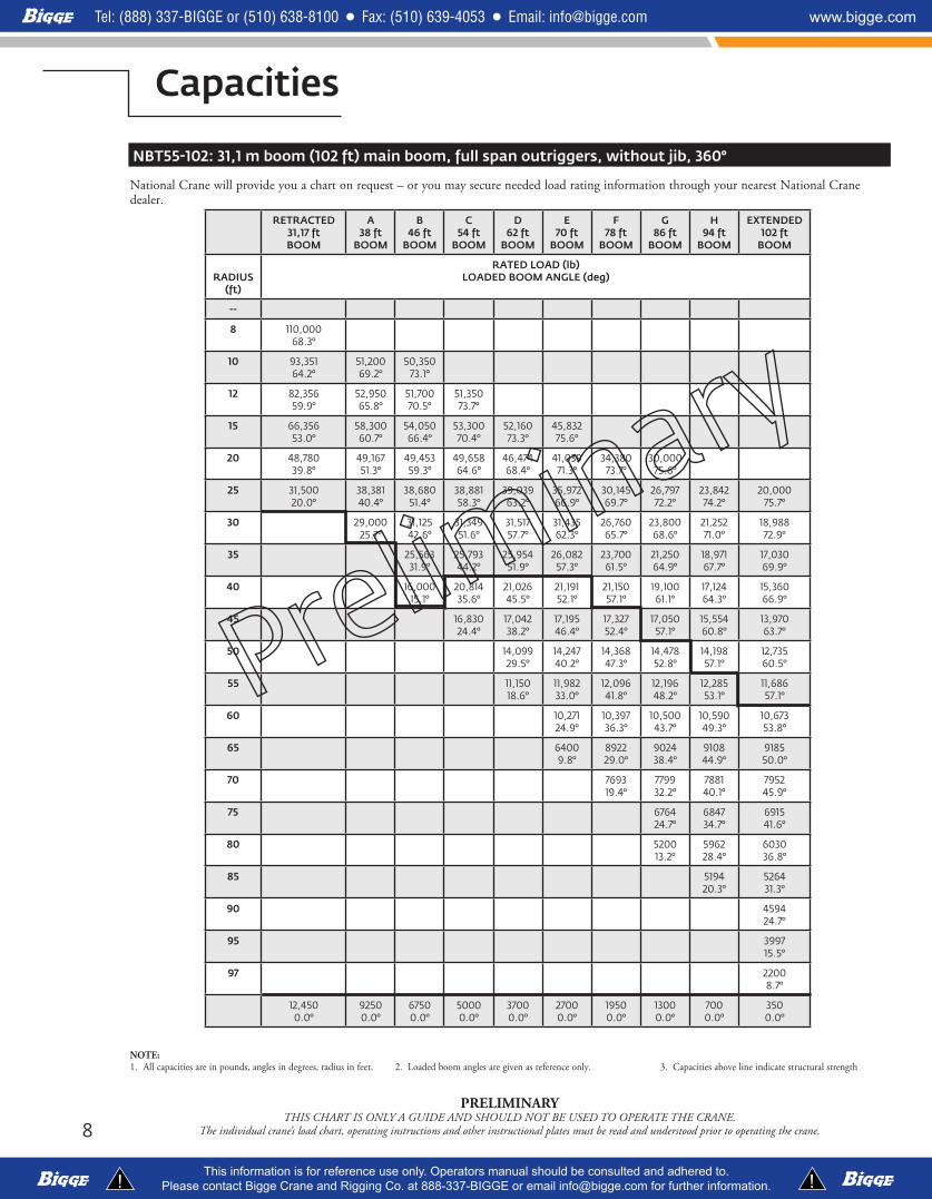
NBT50-102: 31,1 m boom (102 ft) main boom, full span outriggers, without jib, 360°
National Crane will provide you a chart on request – or you may secure needed load rating information through your nearest National Crane dealer.
NOTE:1. All capacities are in pounds, angles in degrees, radius in feet. 2. Loaded boom angles are given as reference only. 3. Capacities above line indicate structural strength
PRELIMINARYTHIS CHART IS ONLY A GUIDE AND SHOULD NOT BE USED TO OPERATE THE CRANE.
The individual crane’s load chart, operating instructions and other instructional plates must be read and understood prior to operating the crane.
Retracted31.17 ft
A38 ft
B46 ft
C54 ft
D62 ft
E70 ft
F78 ft
G86 ft
H94 ft
Extended102 ft
RADIUS (ft)
RATED LOAD (lb)BOOM ANGLE (deg)
--
8 100,00068.3°
10 93,35164.2°
51,20069.2°
50,35073.1°
12 80,98259.9°
52,95065.8°
51,70070.5°
51,35073.7°
15 64,41053.0°
58,30060.7°
54,05066.4°
53,30070.4°
52,16073.3°
45,83275.6°
20 47,29939.8°
47,68651.3°
47,97159.3°
48,17564.5°
46,47468.4°
41,03971.3°
34,38073.7°
30,00075.6°
25 31,50020.0°
37,08840.3°
37,41351.4°
37,63258.3°
37,80463.2°
35,97266.9°
30,14569.7°
26,79772.2°
23,84274.2°
20,00075.7°
30 29,00025.7°
29,85442.6°
30,07751.6°
30,24357.7°
30,37962.2°
26,76065.7°
23,80068.6°
21,25271.0°
18,98872.9°
35 23,60531.9°
23,90444.2°
24,11651.8°
24,28557.3°
23,74061.5°
21,25064.9°
18,97167.7°
17,03069.9°
40 16,00015.1°
18,72035.6°
18,92945.4°
19,08752.0°
19,23057.0°
19,10061.1°
17,12464.3°
15,36066.9°
45 15,05324.4°
15,26338.2°
15,41146.4°
15,53752.3°
15,65757.0°
15,55460.8°
13,97063.7°
50 12,55429.5°
12,70040.1°
12,81547.2°
12,92052.6°
13,01756.9°
12,73560.5°
55 10,54918.5°
10,71733.7°
10,83842.3°
10,94348.5°
11,03753.3°
11,12557.3°
60 904724.8°
917136.2°
927043.6°
935649.2°
943553.6°
65 64009.9°
781329.0°
791138.2°
799244.7°
806549.8°
70 668019.3°
678332.1°
686239.9°
693045.7°
75 583024.6°
591034.6°
597541.4°
80 500513.2°
509528.3°
516036.6°
85 438720.1°
445531.1°
90 383724.6°
95 328815.3°
97 20008.7°
12,4500.0°
92500.0°
67500.0°
50000.0°
37000.0°
27000.0°
19500.0°
13000.0°
7000.0°
3500.0°
8
Capacities
PRELIMINARYTHIS CHART IS ONLY A GUIDE AND SHOULD NOT BE USED TO OPERATE THE CRANE.
The individual crane’s load chart, operating instructions and other instructional plates must be read and understood prior to operating the crane.
NOTE:1. All capacities are in pounds, angles in degrees, radius in feet. 2. Loaded boom angles are given as reference only. 3. Capacities above line indicate structural strength
NBT55-102: 31,1 m boom (102 ft) main boom, full span outriggers, without jib, 360°
National Crane will provide you a chart on request – or you may secure needed load rating information through your nearest National Crane dealer.
RETRACTED31,17 ft BOOM
A38 ft
BOOM
B46 ft
BOOM
C54 ft
BOOM
D62 ft
BOOM
E70 ft
BOOM
F78 ft
BOOM
G86 ft
BOOM
H94 ft
BOOM
EXTENDED102 ft
BOOM
RADIUS
(ft)
RATED LOAD (lb)LOADED BOOM ANGLE (deg)
--
8 110,00068.3°
10 93,35164.2°
51,20069.2°
50,35073.1°
12 82,35659.9°
52,95065.8°
51,70070.5°
51,35073.7°
15 66,35653.0°
58,30060.7°
54,05066.4°
53,30070.4°
52,16073.3°
45,83275.6°
20 48,78039.8°
49,16751.3°
49,45359.3°
49,65864.6°
46,47468.4°
41,03971.3°
34,38073.7°
30,00075.6°
25 31,50020.0°
38,38140.4°
38,68051.4°
38,88158.3°
39,03963.2°
35,97266.9°
30,14569.7°
26,79772.2°
23,84274.2°
20,00075.7°
30 29,00025.7°
31,12542.6°
31,34951.6°
31,51757.7°
31,43562.3°
26,76065.7°
23,80068.6°
21,25271.0°
18,98872.9°
35 25,56331.9°
25,79344.2°
25,95451.9°
26,08257.3°
23,70061.5°
21,25064.9°
18,97167.7°
17,03069.9°
40 16,00015.1°
20,81435.6°
21,02645.5°
21,19152.1°
21,15057.1°
19,10061.1°
17,12464.3°
15,36066.9°
45 16,83024.4°
17,04238.2°
17,19546.4°
17,32752.4°
17,05057.1°
15,55460.8°
13,97063.7°
50 14,09929.5°
14,24740.2°
14,36847.3°
14,47852.8°
14,19857.1°
12,73560.5°
55 11,15018.6°
11,98233.0°
12,09641.8°
12,19648.2°
12,28553.1°
11,68657.1°
60 10,27124.9°
10,39736.3°
10,50043.7°
10,59049.3°
10,67353.8°
65 64009.8°
892229.0°
902438.4°
910844.9°
918550.0°
70 769319.4°
779932.2°
788140.1°
795245.9°
75 676424.7°
684734.7°
691541.6°
80 520013.2°
596228.4°
603036.8°
85 519420.3°
526431.3°
90 459424.7°
95 399715.5°
97 22008.7°
12,4500.0°
92500.0°
67500.0°
50000.0°
37000.0°
27000.0°
19500.0°
13000.0°
7000.0°
3500.0°

9Series NBT50
Capacities
PRELIMINARYTHIS CHART IS ONLY A GUIDE AND SHOULD NOT BE USED TO OPERATE THE CRANE.
The individual crane’s load chart, operating instructions and other instructional plates must be read and understood prior to operating the crane.
NBT55-128: 39,01 m boom (128 ft) main boom, full span outriggers, without jib, 360°
National Crane will provide you a chart on request – or you may secure needed load rating information through your nearest National Crane dealer.
NOTE:1. All capacities are in pounds, angles in degrees, radius in feet. 2. Loaded boom angles are given as reference only. 3. Capacities above line indicate structural strength
RETRACTED31,72 ft BOOM
A43 ft
BOOM
B54 ft
BOOM
C64 ft
BOOM
D75 ft
BOOM
E86 ft
BOOM
F97 ft
BOOM
G107 ft
BOOM
H118 ft
BOOM
EXTENDED128 ft
BOOM
RADIUS (ft)
RATED LOAD (lb)LOADED BOOM ANGLE (deg)
--
8 110,00068.1°
10 92,04464.0°
39,75071.3°
12 80,98659.8°
40,85068.5°
40,05073.3°
15 65,24353.1°
42,90064.0°
41,50069.9°
41,20073.5°
20 47,56840.3°
48,33756.2°
46,85064.2°
41,54468.8°
34,83972.5°
26,01575.0°
25 31,30821.8°
37,49347.5°
37,92658.0°
37,22463.9°
30,71668.4°
23,12971.6°
20,00074.3°
30 29,98937.3°
30,46651.3°
30,76358.6°
27,69664.2°
20,85168.0°
18,16271.2°
16,26373.6°
35 22,00423.6°
24,85243.9°
25,13853.1°
25,12959.8°
18,90364.3°
16,65668.1°
15,00070.9°
13,15773.3°
11,70075.1°
40 20,06535.2°
20,41947.0°
20,71655.1°
17,44560.5°
15,41364.9°
13,93668.0°
12,27970.8°
11,05073.1°
45 16,05024.0°
16,40140.3°
16,67450.0°
16,08956.6°
14,25061.5°
12,81065.1°
11,51368.3°
10,41170.9°
50 13,42932.4°
13,68844.6°
13,89152.3°
13,09858.0°
11,93062.1°
10,84565.9°
983568.5°
55 11,13223.4°
11,39138.6°
11,58047.7°
11,76454.3°
11,16459.3°
10,16163.2°
875066.0°
60 967632.4°
987243.3°
10,05150.7°
10,21356.0°
955460.4°
785063.4°
65 817623.8°
837337.9°
854146.6°
868752.4°
884457.5°
700060.7°
70 43489.2°
712831.8°
728942.1°
742348.6°
756554.3°
630057.9°
75 607524.3°
623437.1°
636044.7°
649050.9°
570055.1°
80 406612.8°
533131.5°
545240.4°
557347.4°
520052.2°
85 454924.8°
466735.7°
478143.7°
465049.0°
90 350715.2°
398130.4°
409139.7°
418045.8°
95 337524.0°
348335.4°
356842.2°
100 247914.8°
294330.4°
302538.4°
105 245924.6°
254034.2°
110 202016.7°
210429.4°
115 170823.7°
120 126616.0°
125 12,5752.0°
73041.6°
45251.5°
33932.7°
19122.5°
8332.4°

10
Dimensions
PRELIMINARYTHIS CHART IS ONLY A GUIDE AND SHOULD NOT BE USED TO OPERATE THE CRANE.
The individual crane’s load chart, operating instructions and other instructional plates must be read and understood prior to operating the crane.
����
����
.��
����
����
.��
����
���.
��
����
����
.�� R
ETRA
CTED
�� �
�� ��
���.
�� E
XTEN
DED
���
���.�
�
FRO
NT/
REAR
O/R
SPRE
AD��
�� ��
�.��
/���
� ���
.�� R
ETRA
CTED
����
����
�/���
� ���
�� M
IDSP
AN��
�� ��
��.�
�/���
� ���
�.��
FULL
SPAN
���
���.
��
MAX
CHA
SSIS
WID
TH
����
���.
��M
AIN
HO
IST
����
���.
����
����
�.��
����
����.
��
���
���.
����
� ���
.��
��� �
��.�
�
����
���.
��CH
ASSI
S CAB
CLE
ARAN
CE
����
����
.��
OVE
RALL
WID
TH
����
����
.��
OVE
RALL
HEIG
HT��
�� ��
��.�
�
����
����
.��
TAIL
SWIN
G
�� ��
� ���
�.�� O
VERA
LL LE
NGT
H

11Series NBT50
Accessories
PRELIMINARYTHIS CHART IS ONLY A GUIDE AND SHOULD NOT BE USED TO OPERATE THE CRANE.
The individual crane’s load chart, operating instructions and other instructional plates must be read and understood prior to operating the crane.
Radio Remote Controls – • NB6R
Eliminate the handling and maintenance concerns that accompany cabled remotes. Operate to a range of about 76 m (250 ft), varying with conditions.Remote transmitter displays LMI information on LCD screen.
Personnel Baskets – One and two person baskets, gravity hung with swing lock and full body • B1-Sharness. Fast attachment and secure locking systems. Ratings from 139 kg • 2B1-S (300 lb) to 544 kg (1200 lb) • BSA-1 • BSA-R1 • BSAY-1 • BSAY-2
Auxiliary Winch – Second winch redundant to the main, 15,000 lb gear set, two-speed piston motor, • AWcable packer, grooved drum, DRI/LLI standard with 5/8 in Dyform 34LR wire rope
Spanish-Language Danger Decals, • SDD Control Knobs, and Operators’ Manuals • SOM
Back Up Alarm
Electronic Back Up Alarm (included on factory mounts and shipouts) •BUA
Outrigger Motion Alarm •OMA
Rotation Bearing Lock •MRL
Manual applied lock on rotation bearing (360° positioning)
Metric Capacity Charts •MCC
Dual-Axis Electronic Joysticks •DAJS
In place of single-axis joysticks
Special Paint •SPECIAL PAINT
One color in lieu of standard paint color-non metallic

This document is non-contractual. Constant improvement and engineering progress make it necessary that we reserve the right to make specification, equipment, and price changes without notice. Illustrations shown may include optional equipment and accessories and may not include all standard equipment.
AmericasBrazilAlphavilleMexicoMonterreyChileSantiago
Europe, Middle East & AfricaCzech RepublicNetvoriceFranceBaudemontCergyDecinesGermanyLangenfeldHungaryBudapestItalyParabiagoNetherlandsBredaPolandWarsaw
PortugalBaltarRussiaMoscowU.A.E.DubaiU.K.Gawcott
Asia - PacificAustraliaBrisbaneMelbourneSydneyChinaBeijingXi’anIndiaHyderabadPuneKoreaSeoulPhilippinesMakati CitySingapore
FactoriesBrazilAlphavilleChinaTaiAnZhangjiagangFranceCharlieuLa ClayetteMoulinsGermanyWilhelmshavenIndiaPuneItalyNiella TanaroPortugalBaltarFânzeresSlovakiaSarisUSAManitowoc Port WashingtonShady Grove
Regional offices
Manitowoc - Asia Pacific Shanghai, China Tel: +86 21 6457 0066Fax: +86 21 6457 4955
Manitowoc - Europe, Middle East & Africa Ecully, France Tel: +33 (0)4 72 18 20 20 Fax: +33 (0)4 72 18 20 00
Manitowoc - Americas Manitowoc, Wisconsin, USA Tel: +1 920 684 6621 Fax: +1 920 683 6277
Shady Grove, Pennsylvania, USA Tel: +1 717 597 8121 Fax: +1 717 597 4062
©2009 ManitowocPrinted in USAFormNo.SeriesNBT50PartNo.09-009/1209/1.5M www.manitowoc.com
Regional headquarters