Surface pressure and viscous forces on inclined elliptic ...

29
NATIONAL ADVISORY COMMITTEE
FOR AERONAUTICS
TECHNICAL NOTE
No. 1292
INVESTIGATION OF SUCTION-SLOT SHAPES
FOR CONTROLLING A TURBULENT BOUTh1]DARY LAYER
By P. Kenneth Pierpont
Langley Memorial Aeronautical Laboratory Langley Field, Va.
ENCJr ..EER;N C'PT. LfBRATh' CHA!:c .: ' 'LRAFT
Washington June 1947
https://ntrs.nasa.gov/search.jsp?R=19930081911 2018-08-31T07:30:01+00:00Z

NATIONAL ADVISORY CO4ITJEE OR PZRONAIJTICS
¶ECHNICAL NOTR NO. 1292
INVESTIGATION OF SUCTION-SLOT SHAPES
FOB CONTROLLING. A TtJBBTJLENT BOUNDARY LAYER
By P. Kenneth Pierpont
StJIviMtBY
Tests of three types of boundary-layer-contrój. suction slots have been made in a two-&lmansional diffuser to Investigate design criterlons and to evaluate the practical minimum total-pressure losses. The tests were conducted. at a velocity of about 100 feet per second with a boundary layer which had a displacement thickness of 0.85 inch and a shape parameter of about 1.8.
The shape of the boundary layer behind the slot was found to depend only on the quantity of air removed provided that the slot inlet had rounded edges. Near maximum effectiveness was obtained when the quantity rate of air flow through the slot was equal to that which would pass at free-stream velocity.through an area equal to the displacement thlckn6ss per unit span.
The total-pressure losses through the slot were found to be appreciably reduced by rounding the inlet edges, inclining the slot, slightly diverging the slot walls, and, especially, providing adequate width. The optimum inlet-velocity ratio for a diffuser slot is of the order of 0 Go to o.6. For the foregoing rate of air flow and with around-edge diffuser slot inclined at 3Q0 to the air stream, the total-pressure drop was 18 percent lees than the value for a normal-opening sharp-edge slot. For this configuration only 55 percent of the measured total-pressure drop could be accounted for by the total -pressure deficiency in the part of the boundary layer removed.
iftIS)l
Boundary-layer control by suction, as a means of preventing flow separation on wings and In ducts, has been the subject of a great deal of experimental study; for example,. see references 1 and. 2. The power required for effective boundary-layer control was determined in many of these studies; however, most such power requirements must be con-sidered unnecessarily h1h and, hardly indicative of the power requirements

2
NACA TN No. 1292'
for optimum designs because of the excessive pressure losses through the usually arbitrarilydesigned suction slots. Obviously, if the losses through the suction slots can be minimized, the net difference between the free-stream total pressure and the total pressure in the suction duct need. not greatly exceed the losses already present in the boundary layer that is being removed.
In the present work measurements were made of the add.itionaJ. losses through suction slots of various designs in order to develop design criterions for suction slots and. to evaluate the practical minimum value of such additional pressure losses. Two-dimensional slots of various widths and entrance radii, flush and inclined. at several angles to the surface and with various amounts of angular separation between the two walls, were tested. Only one boundary layer - one with a displacement thiäkness of about 0.85 and. with a shape parameter of about i.8 - was used for the tests.
.sOIs
U local velocity outside boundary layer, feet per second
local dynamic pressure outside boundary layer, pounds per square inch
u local velocity inside boundary layer, feet per second.
H1, H total pressure at stations 1 and. 2 respectively, pounds per square foot
quszitity rate of flow through suction slot, cubic feet per second
y distance normal to surface, inches
b span of suction slot, inches
w width of suction slot, inches
B1 radius of front edge of suction slot, inches
P radius of rear edge of suction slot, inches
boundary-layer displacement thicess, inched (JB(1
- u) dy)
0 boundary-layer momentum thicknes,, inchee(f (i - d)

NACA TN No. 1292 3
boundary-layer thic1ess, Inches
H boundary-laypr shape parameter (*i)
flow coefficIent (Qtbb*1u1)
Cif total -pressure -loss coefficient (H1 q1H•b)
p angle of slot center line with respect to. test surface,, degrees
f3 diffuser an1e, degrees
. distance normal to surface "at station 1, which Is determined • by the amount of boundary layer removed.; that Is, when
the part of the boundary layer between y = 0 and y = h at station 1 is removed, inches .
mean total pressure of part of boundary layer to be removed, • . pounds per square foot
total-pressure loss through suction slot, pounds per square foot .
Subscripts . . ..
b conditions in suôtion chamber
1 c'ondition at station 1, 5 Inches ahead of center . line of suction slot : .
2 conditions at station 2, 1 Inches behind center line of suction slot
APPARATUS AID MODELS
• The tests were conducted on a flat wall of a two-dimensional
diffuser which was., attached, to the entrance. 'cone of the -scale model
of the fu11-ca1e wind. tunnel described in reference 3 . Figure 1 is a "diagranatIc. ' sketch ,f the princlpal..parts. of the 'apparatus used In tests' of boundary-layer-coiitrol suction sloth..
The top and. bottom of the diffuser and the side of the diffuser on which the slots were lócated'were flat; the side opposite the test wall was adjustable. k 'vane (in the form of an airfoil) and. three boundary-layer bleeds on the adjustable wall were used, to maintain
NACA TN No. 1292
nonseparated flow on the adjustable wall. Pressure to force air through the bleeds was obtained by placing a 16-mesh screen at the diffuser exit. The suction chamber (fig. 1) consisted of a large plywood box. A 100-mesh screen located 3 inches from the back of the box served to eliminate any local excesses of suction near the center of the box, where the suction duct was attached.
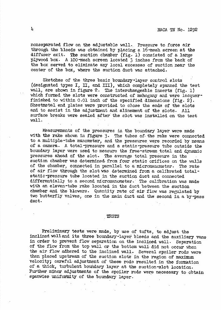
Sketches of the three basic boundary-layer conbol slots (designated types I, II, end. III), which completely spanned the test wall, are shown in figure 2. The interchangeable inaerta (fig. 1) which formed the slots were constructed of mahogany and were lacquer finished to within 0.01 inch of the specified dimensions (fig. 2). Sheetmetal end plates were provided to close the ends of the slots and. to assist in the adjustment and. alineinent of the slots. All surface breaks were sealed after the slot was installed on the test wall. .
Measurements of the pressures in the boundary layer were made with the rake shown in figure 3 . The tubes of the rake were connected to a multiple -tube manometer, and. the pressures were recorded by means of a camera. A total-pressure and. a static-pressure tube outside the boundary layer were used to measure the free -stream total end dynamic pressures ahead. of the slot. The average total pressure in the suction chamber was determined, from four static orifices on the walls of the chamber, connected in parallel to a inicromanometer. The rate of air flow through the slot was determined from a calibrated total-static-pressure tube located in the suction duct and. connected differentially to a second inicromanometer. The calibration was made with an eleven-tube rake located in the duct between the suction chamber and. the blowers. Quantity rate of air flow was reaulated by two butterfly valves, one in the main duct and. the second in a by-pass duct.
STS
Preliminary tests were made, by use of tufts, to adjust the inclined wall and its three boundary-layer bleeds and the auxiliary vane in order to prevent flow separation on the inclined wall. Separation of the flow from the top wall or the bottom wall did not occur when the air flow adhered to the inclined wall. Several spoiler rods were then placed upstream of the suction slots in the region of maximum velocity; careful adjustment of these rods resv.lted. in the formation of a thick, turbulent boundary layer at the suction-slot location. Further minor adjustments of the spoiler rods were necessary to obtain spanwise unifoimity of the boundary layer.

NACA TN No. 1292 5
With several different slots In position, tests were made for a range of rate of air flow up to 20 cubic feet per second to verify the uniformity of the total pressure in the suction chamber. Since the main tests were run with the rake removed at station 1, preliminary tests were also made to determine the relation between the dynamic pressures at stations 1 and 2 (fIg. i) as a function of the quantity of air removed through the slot end to verify the fact that the relation was not a function of the slot design.
For the main tests simultaneous measurements were made of the boundary-layer total and static pressures at station 2, the average total pressure in the suction chamber, and. the quantity rate of air flow through the slot. The following slot configurations were tested:
Type I. Sharp-edge slots with straight parallel sides Inclined at angles p with respect to the test wall of 9O, 600
and. 30° and with slot widths w of 0.38, 0.63, end 0.75 inch. One test was made for p = 900 and. w = 1.50 inches.
Type II. Slots sinilar to type I but with rounded edges and with P1 R2 = o.o6, 0.13, 0.25, and 0.38 inch, o, 60°, 1O
and 3Q0, and. w = 0.75 inch. An additional test was made for p = 90, w = 0.75, R1 = 1.50, and. P2 = 0. 38 inches.
Type III. Slots with rounded edges and diverging walls (ratio of exit area to entrance area constant and equal to 2) with P1 = 1.50 inches and P2 = 0.25 Inch, p = 90°, O,
and 300, and. i 0.75, 1.25, aiid 1.75 inches (except p = 30° for which w = 0.75, 1.13, and 1.50 inches). The larger values of were Included In these tests after It became clear that the smaller values could result in very large losses at the higher flow coefficients; it must be. admitted, however, that such large slots in a wing surface may present difficult design problems. Diffuser angles 13 of 120, i8°, and 2L.° were tested for each combination of slot angle and. slot width. One test was also made for p = 11.5°, w = 0.75 inch, and. 13 = 6°.
The tests were made at a velocity outside the boundary layer of about 100 feet per second with quantity rates of air flow through the slots up to about 20 cubic feet per second. The turbulent boundary layer at the slot was approximately 3 inches thick and had values of displacement thickness 6* and. shape parameter H ofabout 0.85 inch and 1.8, respectIvely. The Reynolds number based on the momentum thickness was.. approximately 25,000.

NACA TN No. 1292
PESUIJTS MD DISCUSSION
Preliminary tests showed that the d.lsplacenient thickness 8* and. the shape parameter H of the initial boundary layer at station 1 ahead of the slot remained constant within 5 percent for the entire range of air-flow rate. tested. With the slot sealed. the dynaini.c pressure outside the boundary layer was essentially the same at station 2 as at station 1 and., although friction between stations 1 and 2 should cause an increase of about 3 percent in the momentum thickness, the measurements showed no appreciable change in either momentum thickness or displacement thickness between the two stations.
The flow coefficient 1c = .. \ and. the total-pressure-loss / Q b81U1)
coefficient .(C = were referred. t& the stream velocity q1j
and. dynamic pressure at station 1 ahead of the slot.
T I slots (straight sharp -edge) . - Typical boundary-layer velocity profiles at station 2 are shown in figure 1 for several rates ci' air flow through a type I slot (p = 90°, w = 1.50 in.) The no-flow curve was obtained with the slot sealed. Mean curves of the bound.ary layer shape parameter H and the displacement-thickness ratio 8*2
for all the type I slots are shown in figure 5 . No systematic
1 8* variations of H and. 4.. were observed for the different slot bi angles or slot widths, and. .the maximum deviation of the diplacement thickness from the meañiralue was less than 5 percent for most con-ditions. Nearly maximum effectiveness appears to have been obtained when c = 1 since the shape. parameter is approximately equal to the
value for a--powor velocity profile, and. the displacement thickness
has been reduced. to about 0.20 of its initial value.
The maitude of the total-pressure-los coefficient cr plotted
against flow coeff.lclent is shown in figures 6(a), 6(b), 6(c), and. 6(d) for slot angles of p = 90°, 60 0 , t.5° , and 309, respectively. The total-pressure-loss coefficient- appears to drop rapidly as the slot width increases. No very consistent effect of slot angle can be seen. The high losses shown in the uppermost curve of figure 6(a) may be due to particularly violent flow separation from the rear edge and. may thus indicate that, for high inlet-velocity ratios, slot angles as small as 300 may be harmful for share-edge slots.

NACA No. 3292 7
Type II slots (st±ait,wtt1Lrcund_ed.gej . - Results of a few tests to determine the effect at station 2 of slightly rounding both front and rear edges of the slot simultaneously are shown In figures 7 and 8, from which the variation with flow coefficient of the profiles and. of the mean values of the shape parameter and. the displacement thickness ratio can be seen. A small Improvement In the external flow is observed for the type II slots by a comparison of the curves in figure 8 with those of figure 5 for type I slots. For the flow coefficient = 1 the displacement thIc1ess has been reduced
to o.ili. of Its Initial value.
Curves for total-pressure-loss coefficient against flow coef-ficient for the four slot angles are shown in figure 9 . Reductions in excess of 30 percent from the corresponding type I slots were obtained by slightly rounding the slot edges. Since the reduction In total-pressure-loss coefficient which resulted from an Increase In the front radius from B 3 = 0.38 to B1 1.50 inches was small, further reductions did not appear feasible; therefore subsequent tests with a diffuser slot employed a front radius of B1 = 1.50 Inches.
TYIS III slots (round-edge diffuser of area ratio 2) . - Curves of the mean values of shape parameter and displacement-thickness ratio for all the type III slots are shown in figure 10. Comparison of the curves of this figure with the curves for the two previous types (figs. 5 end 8) Indicates that, once the slot edges have been rounded, the effectiveness of boundary-layer control by'suction is primarily dependent on the quantity of air removed.
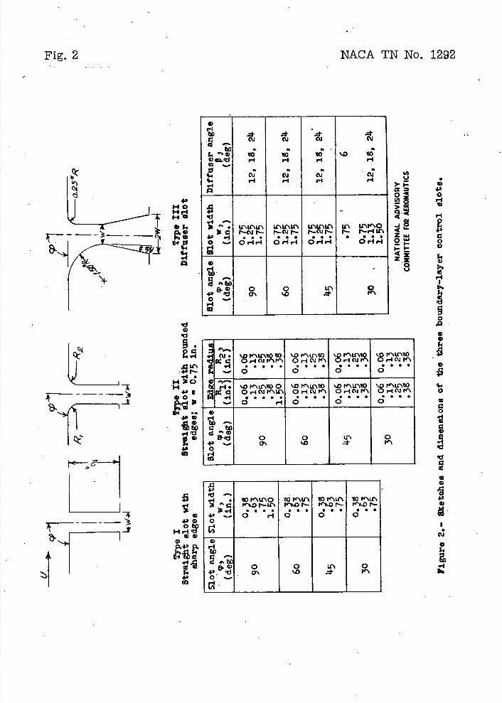
Total-pressure-loss coefficients are plotted against flow coef-ficient f or the type III slots in figure 11. The effect of a change of slot width, slot angle, or diffuser angle can be seen by comparing the corresponding curves 'of these figures. The diffuser appears to offer a powerful means for reducing slot losses as can be seen by coxnparing'the curves of figure 9 and figure 11 for w = 0 . 75 inch (although the larger value of B1 for the diffuser slots probably
also contributed somewhat to the improvement). The 120 diffuser gave lower total-pressure-loss coefficients than the 180 or 211.0 diffusers for all slot widths and. slot angles through the entire range of flow coefficient tested. In order to determine what further improvement might be obtained, one test was made for a slot with the same area ratio, but with a smaller diffuser angle (p = 11.50, w = 0.75 in., = 60). No appreciable inproveinent was observed. Reducing the slot angle showed appreciable improvement, especially for the narrower slot (p = 30°) at flow coefficients less than.l.0; the 0.75-inch slot was almost as efficient as the 1.50-Inch slot.

8 NACA'TN No. 1292
Comparison of the values oftotal-presure-1o8'COeffiCiO fl't for a normal-ening type I slot with the best diffuser slot 'of the same width indicated a reduction of about li.8 percent for a flow coefficient Cq = 1. For this flow coefficient the total-pressure -loss coefficient
for the best slot was CHb = 1.22.
Two tests were ' made with modifications to the beat diffuser slot (p = 3(30, w =1.50 in., and. f3 = . 12°) in an effort to obtain further improvements in the flow through thO slot. Because splitter vanes have been used effectively to reduce large losses associated, with unstable and. irregular flow in some airplane inlet installations, the inlet opening was divided into several low-aspect-ratio openings by placing first three end. later, five splitter vanes in the slot. Neither of these modifications, however, altered the results.
Estimation of losses through the suction slot.- The total-pressure loss may be broken down into two parts: the total-pressure defioiency in that part of the boundary layer which is removed and the total-pressure loss attending the flow through the slot. Thus, if there is no appreciable mixing between station 1 and the slot Inlet
H -HH C +-- (1)
where
mean total pressure in the boundary layer to be removed., measured at statipn 1
total-pressure loss through'the slot
The 'total-pressure deficiency in the removed boundary layer is
dy H, -H
=1 - Ph, (2)
I (--d J° \U/
where h is the distance normal to the surface at station 1 which' determines the amount of the boundary layer removed..

NACA TN No. 1292
Ph I
Similarly
\uj cQ=_f()dY=
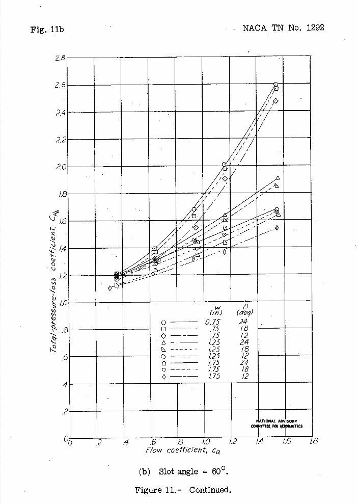
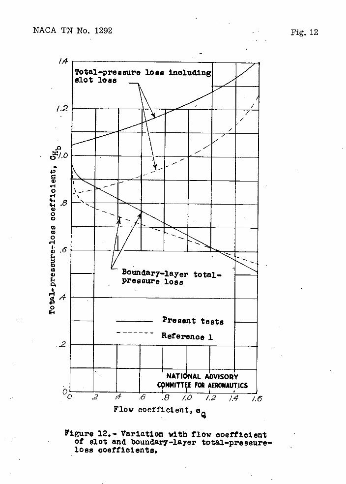
The integrals of equations (2) and. (3) were computed from the data at station 1 and. are plotted in figure 12 as a curve of slot and boundary-layer total-pressure-loss coefficient against flow coefficient. The corresponding curve for the total-pressure-loss coefficient for the type III slot (p = 30, w = 1.50 in., and $3 = 12°) is also shown.
Figure 12 shows that for a flow coefficient of 1.0 the deficiency in. the boundary layer is about 0.67q1, or about 55 percent of the
measured total-pressure -loss coefficIent. The remaining 11.5 percent, about 0 .55q, represents the further loss attending the flow through
the , slot. Presumably the very low total pressure near the bottom of the boundary layer results in violent flow separation from the inner wall of the slot; nevertheless, the 0.55q1 loss seems remarkably
high, since it even exceeds the average dynamic pressure at the throat of the slot which is only about 0.36q1 . It is of interest to note that the best of the narrower slots (p = 30 0 , w = 0.75 in., and $3 = 12°), although not as efficient as. the 1.50-inch slot, at least gave values of that are more readily explained In terms of the commonly recognized. diffuser losses. For this. slot the inlet velocity
* 0 o1_ , at c 1.0 is = 1.21 tImes the free-stream velocity. Q W 0.75 The inlet dynamic pressure Is then (1.2l) 2q1 = l. li.6q1 . Since the
diffuser expansion ratio is 2:1, one-fourth of this dynamic pressure (or 0.37q,) is lost at the diffuser outlet. An additional diffuser lose of aout 0.15 times the dynamic pressure at the Inlet (or 0 .22q1)
may be assumed. The calculated value of for this case Is thus about O.59q1, which is reasonably close to the measured value of 0.68q1 . The total-pressure loss for the narrower slot thus lends
Itself to 'an approximate evaluation, whereas the loss for the wider one does not. A detailed study of the flow Into the slot might show the origin of the total-pressure loss in the case of the wider slot and. Indicate methods of reducing Its magnitude.

10 NCA TN No. 1292
In figure 12 are also shoni, for comparison, corresponding curves determined from the data of reference 1 (dashed lines). The diffuser slot used in those tests was inclined 100 to the wall, had. a well-rounded front edge but a sharp a-ear edge, and had a slot width
of = 1.55, which compares with = i.6 for the present tests.
The loss through the slot (the difference between the two dashed curves) is appreciably less than that found in the present tests, probably because of the relatively higher total pressure near the bottom of the boundary layer.
Remarks on optimum flow coefficient and o ptimi,n slot width.- The results of reference 2 indicate that the optimum flow coefficient will be about unity (CQ = 1.0) for boundary layers which have a shape
parameter near 1.8. Reducing the value much below 1.0 considerably decréasés the effectiveness of the boundary-layer control, whereas increasing'the value much above 1.0 results in relatively little further improvement while greatly increasing the necessary suction power and the amount of equipment. The velocity profiles of figure 7 may be considered as further evidence, for the curves show rapid reduction in both boundary-layer thickness and boundary-layer shape parameter as cQ approaches 1.0, with little possibility of further
improvement beyond this point.
For this flow coefficient of unity the curves of figure 11 show that the intermediate slot widths (1.13 to 1.25 in.) were appreciably more effective than the smaller slot width (0.75 in.) but not appreciably less effective then the largest slot widths (1.50 to 1.75 in.). For type III diffuser slots tested, inlet widths of the order of 1.58* appear to be adequate for CQ = 1.0; or, in general,
an inlet velocity of about 0.65 appears to be indicated. An approxi-mately similar result was obtained in reference 1, where it was found that inlet-velocity ratios above 0.6 gave rapidly increasing pressure losses, whereas reducing the inlet-velocity ratio to as low as 0.2 effected a further reduction In total-pressure-loss coefficient of only o.o6. The larger inlet widths are definitely preferable when no diffuser or rounded edge can be provided; if a long inclined diffuser can be provided, higher inlet-velocity ratios appear acceptable and may even reduce the Inlet losses.
CONCLUSIONS
Tests of three types of boundary-layer-control suction slots were made at a velocity of about 100 feet per second with a turbulent

NACA TN No. 1292
11
boundary layer which had. a displacement thicIess of 0.85 Inch and a share parameter of i.8. Results of those studies indicate the following conclusions:
• 1. The characteristics of the new boundary •layer which is formed behind the slot is determined, only by the quantity of air removed, provided that the slot inlet has rounded edges.
2. Nearly maximum effectiveness is obtained when the rate of air-flow removal is e gual to the air whichwould. pass at free-stream velocity through an area equal to the displacement thickiess per unit span (flow ccefficient c 0 = i.o).
3. Total-pressure losses through the slot may be appreciably reduced by rounding the 'inlet edges, incliningthe slot, and slightly diverging its walls. Adequate width, however, i the most important, feature of a satisfactory slot.
)4. . The total-pressure coefficient for the best slot tested (slot angle p = 300) was 14.8 percent less than that for a normal-opening sharpedge slot of the same width for = 1.0.
5. The total-pressure loss in the boundary layer represented about 55 percent of 'the measured total-pressure coefficient for the best slot at c 0 1.0.
6. The optimum inlet"velocity ratio for a diffuser lot Is about 0.60 to o.6. The optimum may be lower for the less efficient types of slots end may be higher in certain cases if a long diffuser can be used.
Langley Menmoriaj. Aeronautical Laboratory National Advisory Committee for aeronautics
Langley Field, Va., March 10, 1914.7

12
NACA TN No. 1292
1. Gerber, Alfred: Investigation on Removal of the Boundary Layer by Suction. Translation No. 353, Army Air Corps, ter1e1 Div., Sept. 26, 1914.1. 'roirx Nittellungen aus deni Inst. f. Aerod., No. 6, 1938.) LAvailable on request from Air Documents Division, Air Materiel Command, Wright Field, Ohio.)
2. quinn, John H., Jr.: Test$ of the NACA 653 -018 Airfoil Section
with Boundary-Layer Control by Suction. NACA CB No. L4.H1O, 1914k..
3. Theodorson, Theodore, and Silverstein, Abe: Experimental Verification of the Theory c>f Wind-Tunnel Boundary Interference. NACA Rep. No. 14.78, l9314.

NACA TN No. 1292 Fig. 1
a)
a) 0 El 0
a)
0
4.,
H
0
• . i-I • .
a) U)
. a ;• a)
a) 1.1) H S.
a) a)
0 a) E
. . )--. o.. C)
• 0) H I >a0
a) E
I__)_.
a -Jo4-4
o 0 H 4) x 03
I 0 0
I 0• 4.40)
I I 4)
I a) p.40) 0)0 I a)'d 0 )a) 4)0) -. I jU) I 4, Hr-I I
—r14I
a) 4.) a)• I '40) 0
H 4)0
C) a
4.) 00 o 0 .rl H 4) 0) C)
a)H
a)
a)
4' H
a) 0
H
.rI0
.4-)q-1 q14-' •14 WC) a4
El
(d U
o >
4x
0 I-,
43 0 .4
0
.* C'J C'J CU CU tO a a a a
4'0 10 10 10 '.0 10 r4 r-I ri
a a a a CU CU 01 CU .4 .4 .4 .4
• U'.U\Lc U'.ItIC\ L\IrLC' LC\ U\' C r—c.j N- r— ' N- 1— CU 1— 1— l—i-*
4 _I 0 . a • • Or4r4
S S S 0.4.4 • S S Or-tr-
S • • S 0.4.4
0
4, I-I 0
I-I W
Py1 £1'
o Fs.4
. I" • i '4. H O H 43fl
4'O 0 H r$
.4
43
Fig. 2
NACA TN No. 1292
.iI CU •
.•I'.0 N\LC10 10 0.4CUN\N\
S S S a • 0
'.0 I\Lr\10 Or-4C'4N\ . • . a 0
'.0 l'%U'10 OrlOJt'\ e a • • 0
'.Or4C'Jt\ a • a • 0
-'-a .4 • '.0 r'ir1O 0 '.0 '.0 r'\U\10 '.0 r'\LC\10
dl C O4CJNLC OrlC\JN O,fctIIc\ O.4C'Jr\ MI .4 _t_'
• . . • • 0 i-
a • a a 0
• • • • 0
• • . 0
0
C to as
8-.d 0 0 Lt 0 4— '.0 .4
•-i • 10 Y\Lf\0 10 N\U\ 10 P%LC\ 10 N\LT\ 1 - NtDr—LC tt.01— *.0N- N\'.ON-a 4'.-.
• a • a 0 rIO
a • S S • • 0
• S 0
0
0
C as
& a> 0 0 0 '.0 .*

(I) U
>--o >
0 U
-t.
1'
NACA TN No. 1292
Fig. 3
jo.omotrui qn.aidInw o
IDa)
Wa 0) C .c U) U) . -t C) rj
Hrtj0 ; (i '-I +' 0)0 o c . Ei.-Q C.)
0 .r4 • C) 4.)
U) 0S
cc I 00(l) D-i .0 c' a) 0 C)
+)Q0, .-1 o04-' -l.r1 Q)r) 0
(I) •0Q) CI) ;+)
(1) a) a) + U) a
1) a cij 'd •r4 >' 0)
cfl d .r4 Ci) .c (1) 0)U)O OU) -i
-4 rt U) I I
I) OLr + 0 .r. 4 t')
U) i H 4- H >0 U0 cj 0+' r4CQ0 I oE-'
>•i
CU I rdOH 0i c-CS ü)
U) a) o •.) a 4-fC.Q
U) 0) I0) 'ci U) U) U)
') H4-Cl) C . -4 U)
U) U) ) E o ci4- CU
:1 -' 0) 0v

rr
U >..-a o >
4Ie.
<1
8
a) C)
r-I
0 z
4) 0
4) 'I
4) r14) r4
r4 .r4H o
4)
0 r-1C'J a,0
a,4)
ri) 4)
00 0.1-I .04) 0
U .1-I 04 F-i
S
Fig. 4
NACA TN No. 1292
'. _________ 4x _______________0 U
r4 r4t4F—r--O \ N-*OJr-IrI S.• 55 ____ ____ ____ ____ ____ ____
\ \
\\ \ __ ____ __c
\\
\\
9D i:1
__
tk ___ ___ ___ ___
___
i &

NACA TN No. 1292
Fig. 5
________/fl I—,-
______ __ __ 7' 2
___ V__ __ __ ____
I__._J......._..._. ________________ _______________ I _______________ _______________ _______________ _______________
* r-I
.0.1 10
* .. 0
4.,
..,z
C) '
a, -4'
Q) C) 4 q-4
• ,1 q 1 I
4 4.) •
a)
oa)
0 as H
•0
•0
0
I.-
U 0
.4.)
'-I
0• ''
0 0
o a qj N. \ ' . C fl4
t 'OT!V4 009 UO Tt:r.— UQUI9O tdB ia
4)
U) U •14 4) 0) '-4 Si 4) 4.) 0 Si
U
Si 4)
r
Si.
•d4)
0U) .0 I-I '4
4) '-454 00 '-44-4 '4 '"-'.1 4) 0 00 '-4 0c H4) 4-Ia)
4.) '-I
0 '-4 4)
'-I
Si
. U-'
.&
V 54
o - L\1 0
-: - -. - -
H ' uid odt

i:iiiii . eor'\A c
EEEE!I iiiiiiiiiii4, 0
0 O 0 -4 4' \O .4 '4 • H •
q4 0
o o
ql U)
4 r4
o 0 43 0 43
'0 r-4 4, i-I !fl
0 *
Fig. 6a,b NACA TN No. 1292
• OI'\LC\O r.o - _4 IS ••
— 0 i-I
OoQ
0
4)
r4 00 Q
- 0' 0 43 43 H
'4 0 o c' q 1 r-1 'I 0 o 04' - 0 r4 0 U rI
c'3\O
0 * ("I •-... 0
H0 'uaTo'rJJaoo swot—eB9Id—t0

NACA TN No. 1292
Fig. 6c,d
0 o
a) -4 o a
H
a) Oa C,
4-)
Ou '-I
a)
H C)
* CO
9so•t_aInssax -tO 0 D
I . -
ql 0
—
ou
___I:: . r".o I— -
'IJ ) 'Sr - - c
'UcoT;;aoD 9901-a ssajd-10 -
a)
-I
00
-'
II -4 0 -4
H '4 a,
4-) 0
OH U)
C)

r)
a a) 0
1) •
4.3 0)
F-I 0
4)
0
4)
S
4)43 rlO rI
a a) I-I d) H •1•10
p443
.11
ON 0
00 .r4 4)
04) a)
00
I-I
0 •1-4
S
Fig. 7
NACA TN No. 1292
(0) U —>.--
\ _! __ __ __ __ __ __ __
_-'F * '0 LfJr1r-4
0' O.ILr . . . . 0
0 0 Q
\ V
\
_ _
V
• \ ____
V _ _______
______ ______ - ______ ______ ______ _____________ I ______
CT
-zfl/fl 'iT30I9 A W 8/JTOoIA DO

NACA TN No. 1292
Fig. 8
/ __ ___
;4L
____ ___
a
c\I 0 r1
043
0 ) —I •1•'
-
0 - w
C) —+ C) C)
43
C) •4 43 .-i 0 0 C) q4 H
. -1 • Pl 43
- I N C) 43 C
-0 C) 0 E •-4
43 o 0
43 rx. H p.
C) q.1 43
0
—
-. 431-4 H
0 N - I9/
aBauoT1_uaweoatta .1 *
'1 I'-S.
z -z - .-z's-'. -•
H ' ouitd edtg
-S
043
I4
rs
• 0 ,-1r1 -5--14-i
C\J • d0
o
- •-
4-i a) - 0
'-4 •4 r\0 C) ---4 43 C)
9-i C) - 9-i C) cd
C) - 0 ct
p1. C cC
o 0-) C) * 1-I p.
0)Co
-; C)
r4

- ___ 555555 ___ ___ ___ ___
S ..Ø t'\LCVSO ci o,-icur
q. S • S • —0
> I-••
0 a
- f_I • 0 .-4 CJ f4
.•..
q-f 0
OD<
8 0151
4j
'0
.4
U -
_S.
0
c- ) C) H
o 0 'C)
04-' 4,-b
Fig. 9a,b
NACA TN No. 1292
'I0CY)
'uaoçjjOoo sso1-e.inssa.zd — io
Cl)
'ua0 TJJ0O SSO-6.1fl98 d-o
'-I '-4
0
43
54 0
4-i
43
0
0 5l•I '44 4-i 0 0 0
0 H
.ci
.13
.1-4
S 43.11
.1-45-4 C) 'rILf' '4-it-4-4.
0 o ii
0 i-I •
C)43 Si0
C) C) 54
F4 '5 1.3 0 4,
4-i 0
0 -.4 43 '5
Si
I
5-
\1
0
-z 4' 0
C) C;" '-I C) U
c-i C) C) H
o 0 - C) :
0 4,
N___
S N\UO O cj o,-icur'
q.4 S S S S -.-0
\D \LC\O 0 O.-4CJ N\If
• S S • • H
00
___
___
N N

1,0
____ __
. '.0 N\LC\O cJ O,-Icui- q.I . . S I
.- 0
'L(O s-I • Or4Cfl .5..
J
oI
>i
NoD4
z SM-OSM -I-'-I-
____ ___ ___ ___ ___ ___
_______ j____________
o U
4; 0 0 a)
' 0 II
;-I 0) 0) r-4 o bfl
' C) c
o 4-' H 0
0) 'rj
C) 0
S
0
-s-I rx.
'.U3TOTJJ9OO ssoI-sd-ta.O
______ _______ ______S '.0 \LCQ OJ Or4C\fl'\ t s-I • • • - 0
- '0 '\LO • . o••••
oDo
_____ _____ _____ _____ _____ _____
_______
__ __ N\
______
*
U
- 4.' 0
a) .-.5-I
C.-'
C.-, 0)
0) c-I
fl 0 O • C) C
0 4.) rI 0
N
c'4 - -
NACA TN No. 1292
Fig. 9c,d

- H ' " dqg
,-z
0
(c 0 c .C) p4
o p4 H
Fig. 10
NACA TN No. 1292
___ > ____ ___ ___
ii _ -
-7 ______n ____8
V '2 - I 9 1 9 boi •1 *
'-I *
s :1 •CO N
*43
•rl
U UI UI
Q -a) 4.3
4.3 £:: 43 0
4) C) H
,-1 ..-1
p1
,-4 4.3
N c.4 4-'
) 0 c 00)
• C) 4.3 0)
3 C) 4)
0 cS
- p4 .4.3 UI Ca0
5-4
p .4.34-4 0)4-4
5-41-4
0 4301
04.4
a5-4 H C) ".4
go 0 .0O
'-4 4.44-4 0 03 a)
0
a)
0 H a)
-4

__ __p __
________ __
/ 2' 2 ;__ ./ _______ _______ _______ / . - • ______ _
/7 /_-_
---- )>__ ___ ___ ___ ___ __ ___ ___
w (in.) (d99)
o 0.75 24 o ------ .75 /8
.75 /2 1.25 24 1.25 /8
-i---- /25 /2 _____ _____ _____ o /75 24 o ------- 1.75 /8 a--- 1.7.5 /2
NATIONAL ADVI ORY
COMMITTEE FOS UOIIAUTIC
2.6
2.6
24
2.2
2.0
I.
Q.)
q-)
0 U
1.'
Cu
0
) /.O
(4)
Cl)
t.. .
0
4
.2
NACA TN No. 1292
Fig. ha
.2 .4 .6 .8 /0 /2 1.4 1.6 1.8 F/ow coeffic/ent, c,
0 (a) Slot angle = 90
Figure 11.- Variation of total-pressure-loss coefficients with flow coefficient for type Ill slots.
2.8
• ____f .
_
• ______
__
x'A' __ __ __ __ __ __
• w 13 (,',i) (a'e)
o 0.75 24 o ------ .75 /8 Ky ------ .75 /2
/25 24 1.25 /8
u----- 1.25 12 3o 1.75 24 o ------ 1.7$ /8 )----- 175 12
NATIONAL ADVISORY
COMNITICI FC AERONAUTICS
-
2.6
2.4
2.
/.'
zc
ci/..
0 ci
C,)
C,)
'V /.'
I
.1
i8 Itt 1.0 .0 .J I.0
F/ow coefficient, CQ
(b) Slot angle = 60°.
Figure 11.- Continued.
Fig. lib NACA TN No. 1292

NACA TN No. 1292
Fig. lic
2.
2.6
2.4
1'
2.0
1
4
4
£
'4/ (in.) (de9)
o 0.75 24 o ------.75 18 0---- .75 /2
/25 24 1.25 /8 /25 /2
o 1.75 24 o /75 /8 o --- 175 /2
NATIONAL AD ISOY
COMNITTU FOR AERONAUTICS
.2 .4 .6 .8 1.0 1.2 1.4 1.6 1.8 F/ow coeff/c/e,t, CQ
LI
(c) Slot angle = 450
Figure 11.- Continued.

Fig. lid NACA TN No. 1292
2.t
2.,
2.
. _ • /7 __
- -. __ _____ __ __ __
___-__
w (in.) (decy)
o 0.75 24
3 ____ . ____ 75 /8 •--.---- .75 /2
• 1.13 24 1.1.3 /8
12 5 -o --- 1.50 24 o -. /.5O /8 O ----- /50 /2
NATIONAL ADVISORY
COMMITTEE FO AIRONAUTICS.
___ ___ ___- - • - .L
'-'0 .Z • .t .b .0 i.Ci ,'.
/7ow . coe If/dent,
(d) Slot angle =
Figure 11.:- • Concluded.
ci
0
Li
I V)
I' (I)
S.-
.4.-
1.8
Total-pressure loss including slot loss
/ / / ____ ____ ____
/ ____ ____
..-
I / ----
1/Boundary...layer total-. pre g sur lOSø
Present tests
-- Referenoej
NATIONAL ADVISORY
• ________ ____ CQHMITTEE FOR AERONAUTICS I
1.4
1.2
0
0
4,
•1-1
0 .1-I
0 0 0 0 0 0
I. a).
a) a) a)
01 I
0
2
r
NACA TN No. 1292
Fig. 12
.b .8 /.O 1.2 1.4 1.6
Flow coefficient, 04
Figure 12.. Variation with flow coefficient of slot and boundary-layer total-pressure-loss coefficients,