NASA TECHNICAL NOTE T,N e, t · NASA TECHNICAL NOTE NASA T,N D-5898 e, t ... - form of hypersonic...
27
NASA TECHNICAL NOTE NASA T,N D-5898 e, t AERODYNAMIC INTERFERENCE EFFECTS O N HALF-CONE BODIES WITH THIN WINGS AT MACH 10.03 I NATIONAL AERONAUTICS AND SPACE ADMINISTRATION e WASHINGTON, D. C. e JULY 1970 https://ntrs.nasa.gov/search.jsp?R=19700023516 2018-07-10T12:32:07+00:00Z
Transcript of NASA TECHNICAL NOTE T,N e, t · NASA TECHNICAL NOTE NASA T,N D-5898 e, t ... - form of hypersonic...

N A S A TECHNICAL NOTE N A S A T,N D-5898 e, t
AERODYNAMIC INTERFERENCE EFFECTS ON HALF-CONE BODIES WITH THIN WINGS AT MACH 10.03 I
N A T I O N A L A E R O N A U T I C S A N D S P A C E A D M I N I S T R A T I O N e W A S H I N G T O N , D. C. e J U L Y 1970
https://ntrs.nasa.gov/search.jsp?R=19700023516 2018-07-10T12:32:07+00:00Z

~- I NASA TN D-5898 1- 4. Title and Subtitle
1. Report No.
TECH LIBRARY KAFB, NM
I 111111 11111 11111 lllll lllll lllll lllll Ill1 1111 OL32b3L
2. Government Accession No. 3. Recipient's Catalog No.
5. Report Date
AERODYNAMIC INTERFERENCE EFFECTS ON HALF-CONE I l970
BODES WITH THIN WINGS AT MACH 10.03 6. Performing Organization Code
7. Author(s) 8. performing Organization Report No.
James C. Townsend L-6487 10,~Work Unit No.
9. Performing Organization Name and Address 722-01-10-07 NASA Langley Research Center Hampton, Va. 23365
11. Contract or Grant No.
13. Type of Report and Period Covered 12. Sponsoring Agency Name and Address Technical Note
National Aeronautics and Space Administration Washington, D.C. 20546
~~
14. Sponsoring Agency Code
15. Supplementary Notes
" - - .. - . - 16. Abstract
. "
Halves of cone bodies having fineness ratios of 2 , 4, o r 6 were tested with thin flat wings at Mach 10.03 and Reynolds numbers of 1.2 X 10⁶, 1.5 X 10⁶, or 1.8 X 10⁶. Several wing planforms designed empirically or theoretically to match the shape of the shock wave about the body were investigated for each fineness ratio. Tests were also made with thick wings and with wings having various leading-edge shapes. The wing planforms which matched the actual shock shape provide the highest lift-drag ratios. Increasing the fine- ness ratio of the half-cone body increases the lift-drag ratio but decreases the lift coeffi- cient. Effects of wing thickness and leading-edge shape were very small.
18. Distribution Statement
Unclassified - Unlimited
L ~- 17. Key Words (Suggested by ALithor(s))
Hypersonic flow Aerodynamic interference Half -cone bodies
.. - -~ ..
Security Classif. (of this report) 20. Security Classif. (of this page)
Unclassified Unclassified . .. - _ _ ~
"For sale by the Clearinghouse for Federal Scientific and Technical Information
Springfield, Virginia 221 51
AERODYNAMIC INTERFERENCE EFFECTS ON HALF-CONE BODIES
WITH THIN WINGS AT MACH 10.03
By James C. Townsend Langley Research Center
SUMMARY
Halves of cone bodies having fineness ratios of 2, 4, o r 6 were tested with thin flat wings at Mach 10.03 and Reynolds numbers of 1.2 X 10⁶, 1.5 X 10⁶, o r 1.8 X lo6. Several wing planforms designed empirically or theoretically to match the shape of the shock wave about the body were investigated for each fineness ratio. Tes ts were also made with thick wings and with wings having various leading-edge shapes. The theoretical shock-wave-shape estimates used a r e inadequate for the fineness-ratio-4 and 6 cones. The wing planforms which matched the actual shock shape provide the highest lift-drag ratios. Increasing the fineness ratio of the half-cone body increases the lift-drag ratio but decreases the lift coefficient. Effects of wing thickness and leading-edge shape were very small.
INTRODUCTION
A number of hypersonic vehicle applications require high lift-drag ratios. Favora- ble aerodynamic interference can contribute toward achieving this requirement. Thus, the National Aeronautics and Space Administration has been studying configurations for which useful interference may occur. One such configuration is a body mounted beneath a thin flat wing (e.g., refs. 1, 2, and 3). According to inviscid theory, the wing acts as a reflection plane for the body, maintaining the flow field that would occur for the corre- sponding symmetric configuration. In turn, the body pressure field inside the bow shock wave adds to the normal force on the wing. These interference pressures around the body and on the wing should contribute to the aerodynamic efficiency of the combination. Because of the relatively large skin-friction drag at hypersonic speeds, any part of the wing outside the body shock would be inefficient as a lifting surface at small angles of attack. Thus, wing planforms which match the shock-wave shape about the body should give the greatest interference benefits.
The purpose of the present experimental study was to determine the aerodynamic characteristics of wing-half-cone-body configurations with the wings designed from interference principles - t k t is, the leading edges of the thin wings were to coincide
with the cone shock wave at the design Mach number. However, several analytical methods produced varying predictions of the shock-wave shape depending on the order of terms retained and whether boundary-layer displacement effects were included. Tests of models designed according to the various predictions allow an evaluation of the accuracy of the methods used and of the sensitivity of the useful interference to deviations from the ideal planform.
The tests were made in air in the Langley 15-inch hypersonic flow apparatus at Mach number 10.03. The Reynolds number at the nominal test conditions was 1.2 X 10⁶, 1.5 x 10⁶, o r 1.8 X 10⁶ depending on model length. Each body was a half of a fineness- ratio-2, 4, or 6 right circular cone. In addition to tests with the several planforms of thin wings, the bodies were tested without wings and with thick wings having various leading-edge shapes. The nominal angle-of-attack range was from -8' to 43'.
SYMBOLS
- C
C
CD
CL
Cm
D
f
1
L
m
M
pt
2
mean aerodynamic chord
Chapman-Rubesin constant, - D - T r T p r
drag coefficient, - D qs
lift coefficient, - L qs
pitching-moment coefficient, Pitching moment q S F
drag
twice the cone fineness ratio, (+b)B
body length
lift
power -law exponent
f ree-s t ream Mach number
tunnel stagnation pressure

r
R
R2
S
t
T
Tt
X
(Y
Y
6
6*
17
e
I-1
0
dynamic pressure
radial cylindrical coordinate
shock-wave radius and wing radial coordinate
Reynolds number based on free-stream conditions and body length
planform area
wing thickness
temperature
tunnel stagnation temperature
axial coordinate
angle of attack, referenced to axis of symmetry of full cone
ratio of specific heats
shock-wave shape parameter, (Ro/.?)~
boundary-layer displacement thickness
normalized radial coordinate, r/%
conical half-angle
viscosity coefficient
Mach number perturbation parameter
Subscripts:
b body
B base of body
3

C cone
E exact cone theory
max maximum
r reference
S shock wave
W wing
0 zeroth-order theory
1 first-order theory
Primed quantities include effects of boundary-layer displacement thickness.
THEORETICAL CONSIDERATIONS
Several theoretical estimates of the shock-wave shapes were made in order to design the matching wing planforms. E the conical bodies are considered to be power-
law bodies of revolution (with the power-law exponent equal to 1) , a form of hypersonic similarity solu- - - _ _ _ - x
?Ik? -
\ .' \ \ tion applies. With the shock-wave * '\ B o d y
radius given by m
'1 1
". b O is similar along curves = q t ) . 2 = (f) , the flow
m ". r b = q R '. 61
S h o c k -'r = r l R O (See sketch 1.) In particular, the RODC x m body radius is 5 = q (")m where
61 b 7 Sketch 1 the value of qb for each m is
found by solving the flow equations (ref. 4). In t e r m s of the body radius, the shock radius is then
rb R o = ? l b
This shock radius is a "zero-order" estimate in that it applies as M -c 03. ~
*This solution was used in anticipation of future work utilizing power-law bodies.
4

To obtain the effect of finite Mach numbers to first order , a perturbation is applied so that
R1 = "(1 rb + U) qb
According to reference 4, the shock-wave angle is related to the cone angle by
fo r 8, << 1. (Note that these angles are measured in radians.)
Hence,
The shock-wave angle Os can also be found from exact numerical solutions for inviscid flow over cones. Then,
RE = x tan es = rbf tan 8, (3)
where O s is here found from tables such as those of reference 5.
The foregoing estimates do not account for the outward displacement of the shock wave caused by growth of the boundary layer (B.L.) To include this effect, the boundary- layer displacement thickness 6* was added to the body radius to obtain an effective radius rh = r b + 6 . Replacing 'b with r b + 6 in equations (I), (2), and (3) pro- * * duced the following estimates of shock-wave radius:
The same values of %, u, and 8, were used as in the equations without boundary- layer effects. The displacement thickness was calculated by the following equation for adiabatic, laminar boundary layers from reference 4, evaluated for m = 1:
The Chapman-Rubesin constant C was taken to be 1.0. For m = 1, reference 6 gives qb = 0.915. Note that for large-scale vehicles, regions of the boundary layer may become turbulent; therefore, an appropriate method (e.g., refs. 7 and 8) is required for calculation of the displacement thickness.
MODELS
Three full cones were made so that actual shock-wave shapes could be measured from schlieren photographs. These right, circular, stainless-steel cones with fineness ratios of 2, 4, and 6 were 8.00, 10.00, and 12.00 inches (20.32, 25.40, and 30.48 cm) in length, respectively. The bodies for the interference tests were longitudinal halves of identical cones and thus had effective fineness ratios of 2f l , 4@, and 6 n . The wings were 0.020-inch-thick (0.051 cm) stainless-steel sheets brazed to the bodies. (Thinner wings were not practical for fabrication.) Figure l(a) shows a representative wing-body model. Model designations and dimensions a r e given in table I. Ordinates of the wings with curved leading edges are presented in table II. Models W02, W04, and Wo6 had wings with straight leading edges which matched the shock-wave shapes about the three fineness-ratio cones as given by the zero-order theory (eq. (1)). First-order theory (eq. (2)) gave models W12, W14, and W16 which also had wings with straight leading edges. By adding the boundary-layer correction to the zero-order theory (eq. (4)), models Wb2, Wb4, and Wb6 were obtained; by adding the correction to the first-order theory (eq. (5)), models W i 2 , Wi4, and Wi6 were obtained. Exact theory for the fineness ratio-2 cone gave model WE2 (without boundary-layer correction, eq. (3)) and model WE2 (with boundary-layer correction, eq. (6)). Planforms for models wM2 and WM6 were smoothed shock-wave shapes from schlieren photographs of the flow about the fineness- ratio-2 and 6 cones.
A variant of model W k 2 with the leading edge sharpened was designated model Wh2S. Additional models with the same planforms as Wk2, Wi4, and Wi6 but with wings 0.090 inch (0.229 cm) thick were designated Wh2S, Wi2T, W;4T, W;4S, W;4A, Wi4B, and Wi6T. Figure l(b) shows the leading-edge shapes for these wings. Photo- graphs of representative models are presented as figure 2.
Thermal stresses due to the high recovery temperatures deformed the wings of models W i 4 and Wi6 into a permanent waviness which may be seen in figure 2(c). The maximum amplitude was two wing thicknesses with a wavelength approximately twice the wing overhang. This amount of distortion is believed to have had no significant effect on the test results.
6

TESTS
The Langley 15-inch hypersonic flow apparatus used for the tests is a blow-down- type facility which has a running time of 23 minutes and provides an average test-section Mach number of 10.03 in air. This facility is described more completely in reference 9. For the present tests, the nominal stagnation conditions were pt = 972 psia (6700 kN/m2) and Tt = 1106' F (870° K), which give a test-section Reynolds number of 1.5 X 105.per inch (5.91 X 10⁶ per m). The Reynolds numbers based on length of the bodies with cone fineness ratios of 2, 4, and 6 were thus 1.2 X 10⁶, 1.5 X 10⁶, and 1.8 X 10⁶. Thus, the boundary layers on all models were probably completely laminar. Although the static pressure and temperature reached the range for air liquefaction under equilibrium con- ditions, references 10 and 11 along with a corroborating test in this study (fig. 3) have shown that there is sufficient supersaturation under the present test conditions to avoid condensation effects.
A six-component, strain-gage balance in the model measured the forces and moments. A heat-conduction type of absolute pressure gage mounted in the sting mea- sured the base pressure. By assuming that this pressure is constant over the entire model base, the axial-force coefficient was adjusted to the condition of free-stream static pressure on the base. This correction varied approximately from -0.0034 for cone fineness ratio 2 down to -0.0005 for cone fineness ratio 6. The angle of attack was varied from approximately -8' to 8 O and was referenced to the cone axis of sym- metry. Tests of some models were repeated as indicated by multiple points in the data figures.
RESULTS AND DISCUSSION
Shock-Wave Shapes
In figure 3, the shock-wave shapes for the full-cone models are compared with the predicted shapes obtained from equations (1) to (6). For the fineness-ratio-2 cone, the shock shapes obtained by means of the exact and first-order theories with boundary-layer displacement thickness included agree well with the experimentally measured shock loca- tion. When the cone angle is smaller, the shock wave is closer to the body than these theories predict. Adiabatic wall conditions 'are assumed in the estimation of boundary- layer displacement thickness by equation (7). Inasmuch as the actual surface tempera- ture of the cone was on the order of one-half the adiabatic recovery temperature, the actual displacement thickness was somewhat less and the actual shock location was nearer the body than estimated. This effect is less important for larger cone angles since the boundary layer is then thinner. Note that the theoretical shock-wave shapes of figure 3 are approximately the wing shapes of the models.
7

Wing-Planform Variation
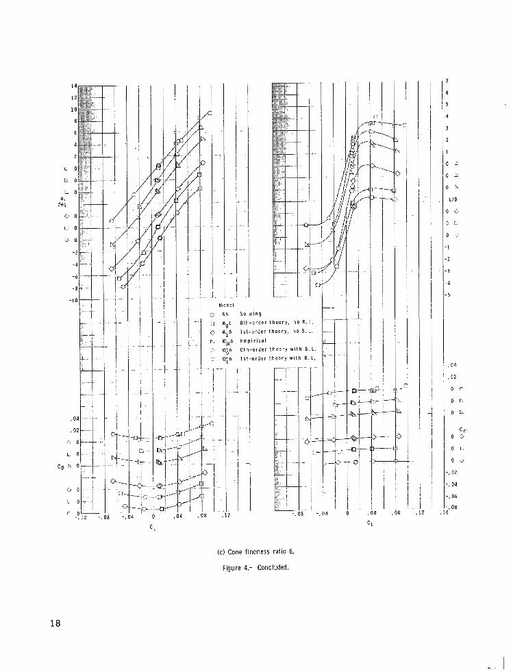
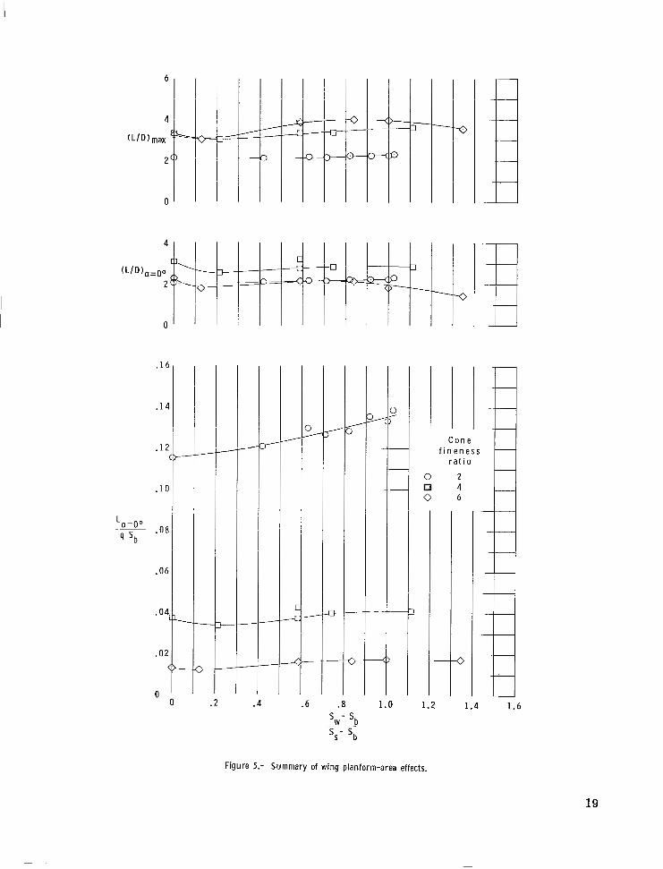
The principal aerodynamic characteristics for the several wing planforms of the three fineness-ratio models are presented in figure 4. The wings have a relatively small effect on the aerodynamic characteristics inasmuch as there are no large deviations from the data for the half-cone bodies alone (circles). In particular, the lift coefficients at zero angle of attack are little affected; there is a small loss which is partially recouped as wing area is increased. Since a! = Oo is the design condition for the wings, this point must be examined more closely. The flat-plate wing alone produces no lift at zero angle of attack; therefore, in this particular case a lift coefficient based on some constant area provides a better comparison of the effects of wing planform. In figure 5, the lift coefficient at a! = Oo based on the body planform area is plotted against the normal- ized exposed wing area. Here, Ss - sb is the exposed area of a wing whose planform matches the empirical shock-wave shape. Note that since both the planform shapes and areas varied, these sets of points do not form smooth curves and thus the fairings only indicate the data trend. The lift generally increases from a low point for very small
wings as the wing approaches the empirical shock-wave shape
the data show no further increase for larger wing areas. The lift-drag ratio at a! = Oo follows the same trend as the lift (fig. 5), but the increase with wing a rea is smaller since the drag r ises with the increased wetted area. For the wing with considerable area out- side the body shock wave, (L/D),p drops as the drag continues to rise with no increase in lift. The same trend occurs for (L/D),, although the levels are differ- ent. As can be seen from figure 4, the angles of attack at (L/D),= a r e low; therefore, the wing area outside the body shock wave does not provide much lift. These observations bear out the expectation that the wing planforms should match the shape of the shock wave about the body. However, this design condition is not critical in that L/D and CL are little changed by moderately large variations in exposed wing area.
(ss - s b 1) h-sb . As expected,
Body- Fineness-Ratio Variation
The aerodynamic characteristics for the three body fineness ratios are compared in figure 6. The planforms of the three wings in figure 6(a) are those nearest matching the shock-wave shape about the body. The characteristics of the three bodies with no wings are shown in figure 6(b). For cone fineness ratio 2 , the lift-drag ratio at the design condition (a! = 0') is very near the maximum lift-drag ratio. As the fineness ratio increases, the angle of attack for (L/D),, also increases and the L/D curve becomes more peaked. Thus, (L/D),O~ is highest for a cone fineness ratio near 4, whereas (L/D),, continues to increase with fineness ratio. Since the available lift coefficient decreases at the same time, the choice of an optimum fineness ratio depends on a trade-off between CL and L/D.
8

With increasing fineness ratio, the variation with angle of attack of the pitching moment about the chosen moment reference center changes from slightly stable to slightly unstable. However, with a reasonable center -of -gravity location the configura- tions could be made stable in pitch throughout the test angle-of-attack range.
Wing Thickness and Leading-Edge Shape
The aerodynamic characteristics for two wing thicknesses and several leading-edge shapes are presented in f igure 7. The fairings in this figure are through the data for the thin-wing models (Wi2 , Wi4, Wi6). For all three fineness ratios, the effects of wing thickness and leading-edge .shape are small. The thicker wing causes a 10-percent higher drag than the thin wing at low lift for cone fineness ratio 2. For the more highly swept wing of the cone-fineness-ratio-6 configuration, the effect of wing thickness was negligi- ble. Similarly, the different wing-leading-edge shapes (fig. 7(b)) do not have any signifi- cant effect on the aerodynamic characteristics of the cone-fineness-ratio-4 configuration. Thus, aerodynamic heating may determine the wing-leading-edge shape for this type of configuration with little penalty in aerodynamic performance.
CONCLUSIONS
An investigation of half-cone bodies with thin flat wings w a s conducted at a Mach number of 10.03. The nominal Reynolds numbers for models with cone fineness ratios of 2 , 4, and 6 were 1.2 x 10⁶, 1.5 X lo6, and 1.8 X lo6, respectively. Several wing plan- forms, designed empirically and theoretically with varying degrees of accuracy to match the shock shape about the body, were tested for each fineness ratio. In addition, tests were made with thick wings and with wings having various leading-edge shapes. The test results lead to the following conclusions:
1. The theoretical methods used to find the shapes of shock waves about a body a r e not adequate for cone fineness ratios greater than 2 at Mach 10. At higher fineness ratios it is necessary to have a better estimate for the boundary-layer displacement thickness.
2. The most effective wing planforms in terms of lift-drag ratio are those which approximately match the shock wave about the full body at zero angle of attack.
3. Increasing the cone fineness ratio under the given test conditions increases the maximum lift-drag ratio but decreases the available lift coefficient.
4. The effects of wing thickness and leading-edge shape are relatively small. Thus, aerodynamic heating may determine these geometrical parameters.
Langley Research Center, National Aeronautics and Space Administration,
Hampton, Va., May 6, 1970.
9

I
REFERENCES
1. Eggers, A. J., Jr.; and Syvertson, Clarence A.: Aircraft Configurations Developing High Lift-Drag Ratios at High Supersonic Speeds. NACA RM A55L05, 1956.
2. Johnston, Patrick J.; Snyder, Curtis D.; and Witcofski, Robert D.: Maximum Lift-Drag Ratios of Delta-Wing-Half-Cone Combinations at a Mach Number of 20 in Helium. NASA T N D-2762, 1965.
3. Fetterman, David E.: Favorable Interference Effects on Maximum Lift-Drag Ratios of Half-Cone Delta-Wing Configurations at Mach 6.86. NASA TN D-2942, 1965.
4. Kubota, Toshi: Inviscid Hypersonic Flow Over Blunt-Nosed Slender Bodies. 1957 Heat Transfer and Fluid Mechanics Institute, Stanford Univ. Press, June 1957, pp. 193-210.
5. Sims, Joseph L.: Tables for Supersonic Flow Around Right Circular Cones at Zero Angle of Attack. NASA SP-3004, 1964.
6. Mirels, Harold: Approximate Analytical Solutions for Hypersonic Flow Over Slender Power Law Bodies. NASA TR R-15, 1959.
7. Spalding, D. B.; and Chi, S. W.: The Drag of a Compressible Turbulent Boundary Layer on a Smooth Flat Plate With and Without Heat Transfer. J. Fluid Mech., V O ~ . 18, pt. 1, Jan. 1964, pp. 117-143.
8. Persh, Jerome; and Lee, Roland: Tabulation of Compressible Turbulent Boundary Layer Parameters. NAVORD Rep. 4282, May 1, 1956.
9. Putnam, Lawrence E.; and Brooks, Cuyler W., Jr.: Static Longitudinal Aerodynamic Characteristics at a Mach Number of 10.03 of Low-Aspect-Ratio Wing-Body Con- figurations Suitable for Reentry. NASA TM X-733, 1962.
10. Daum, Fred L.: Air Condensation in a Hypersonic Wind Tunnel. AIAA J., vol. 1, no. 5, May 1963, pp. 1043-1046.
11. Putnam, Lawrence E.: Investigation of Effects of Ramp Span and Deflection Angle on Laminar Boundary-Layer Separation at Mach 10.03. NASA TN D-2833, 1965.
10

TABLE I.- MODEL DESIGNATIONS AND GEOMETRIC CHARACTERISTICS
Length, Fineness ratio aerodynamic ' radial coordinate in. cm
Planform Ratio of mean Ratio of wing
of cone area ratio, chord to body to body length, Model * Remarks 'Isb length, F / l RB/l
B2 B4 B6
2 8.00 20.32 1.0000 0.6667 0.2500 Half- cone body alone, 4 10.00 25.40 1.0000 .6667 .1250 no wing. 6 12.00 30.48 1.0000 .6667 .0833
2 8.00 20.32 1.0940 0.6667 0.2735 Zero-order theory with- 4 10.00 25.40 1.0953 .6667 .1369 out boundary layer 6 12.00 30.48 1.0940 .6667 .0912 (es. (1)).
2 8.00 20.32 1.1601 0.6667 0.2900 First-order theory with- 4 10.00 25.40 1.3312 .6667 .1664 out boundary layer 6 12.00 30.48 1.6220 .6667 .1352 (es. (2)).
WE2 2 8.00 20.32 1.1848 0.6667 0.2963 Exact cone theory with- out boundary layer
(es. (3)).
Wb2 2 8.00 20.32 1.1418 0.6718 0.2825 Zero-order theory with wb4 4 10.00 25.40 1.2616 .6838 .1525 boundary-layer correc-
w; 2 2 8.00 20.32 1.2066 0.6717 0.2988 First-order theory with
Wb6 6 12.00 30.48 1.4368 .6977 .1127 tion (eq. (4)).
Wi4, Wi4T, W;4S, Wi4A, Wi4B 4 10.00 25.40 1.4966 .6811 .1819 boundary-layer correc- Wi6, Wi6T 6 12.00 30.48 1.9975 .7418 .1665 tion (eq. (5)).
Wk2, Wk2S, Wg2T 2 8.00 20.32 1.2313 0.6716 0.3049 Exact cone theory with boundary-layer correc-
I tion (eq. (6)).
WM2 2 8.00 20.32 1.2253 0.6768 6 WM6
0.3011 Empirical (from measured 12.00 shock-wave shapes). .1408 .6812 1.7411 30.48
*Model notation: B body alone W wing-body combination Suffixes A, B, S, and T denote leading-edge shapes shown in figure 1.

TABLE II.- ORDINATES OF WINGS WITH CURVED LEADING EDGES
.15
.20
.2 5
.30
.35
.40
.45
.50
.55
.60
.6 5
.70
.75
.80
.85
.90
.95 ~ 1.00
I 0.01 56 .0301 .044 5 .0587 .0728 .086 9 .lo1 0 .1150 .1291 .1431 .1571 .1705 .1850 .1990 .2129 .2269 .2408 .2547 .2686 .2825
0.0165 0.0168 .0318 .0324 .0469 .0478 .0619 .0631 .0769 .0784 .0918 .0936 .lo67 .lo88 .1215 .1240 .1364 .1391 .1512 .1543 .1660 .1694 .1808 .1845 .1956 .1996 .2103 .2146 .2251 .2297 .2398 .2448 .2546 .2598 .2693 .2749 .2840 ' .2899 .2988 .3049
.0505
.06 54
.0806
.0949
.lo90
.1228
.1376
.1527
.1677
.1826
.1976
.2125
.2277
.2424
.2571
.2719
.2868
.3011
I wb4
0.0103 .0186 .0266 .0344 .0420 .0496 .0571 .0646 .0721 .0795 .0869 .0942 .lo16 .lo89 .1162 .1235 .1308 .1380 .1453 .1525
I I I
0.0118 0.0093 0.0138
~
.0216
.0310
.0402
.0494
. 0 584
.0674
.0764
.0853
.0942
.lo30
.1119
.1207
.1295
.1382
.1470
.1557
.1644
.1732
.1819
.0220
.0278
.0335
.0391
.0446
.O 500
.0554
.0607
.0660
.0713
.0765
.0818
.0869
.092 1
.0973
.lo24
.lo7 5
.1127
.023 5
.0325
.0411
.0495
.0578
.0659
.0739 ,0819 .0898 .0976 .lo54 .1131 .1208 .1285 .1362 .1438 .1514 .1589 .1665
0.0088
.0237
.0311
.0382
.04 51
.0521
.0592
.0660
.0731
.0802
.0874
.0941
.1007
.1077
.1142 ,1208 .1275 .1341 .1408

i', = . 0 2 0 in. (.051 cm) !
M o m e n t
c e n t e r - 2
T 2 4 ; r e f e r e n c e t 2 = . 0 9 0 in. ( . 2 2 9 cm)
I
I T y p i c a l t h i n w i n g
i
I
/ w;4s
I W; 4A
(a ) Model configuration and sting location. (Table I gives dimensions ( b ) Section A-A showing leading-edge shapes. (Enlarged scale.) and table I I gives curved leading-edge planforms.)
Figure 1.- General model configuration and leading-edge shapes.

(a) Full-cone models.
Wi 4
i
i
(c) Edge view of deformed wings.
i I
\ Wi6
(b) Three models of cone fineness ratio 4.
Figure 2.- Several models used in present study. L-70-1627
14

I _. . _... , .. .. . . .. . - . .. . .. .
.16
.12
R / Z .08
. 0 4
0
. 2 0
.16
. 1 2
R / l
.08
. 0 4
0
. 3 2
. 28
. 2 4
. 2 0
R / 1 . 1 6
.12
.08
. 0 4
0
B
L 0 1
( a ) F i n e n e s s r a t i o 6.
( b ) F i n e n e s s r a t i o 4.
," B
f I, S u p e r s a t u r a t e d f l o w n U n s a t u r a t e d f l o w
E x p e r i m e n t I l l T h e o r y
0 t h o r d e r , n o B . L . - . - - " . - 1 s t o r d e r , n o B.L .
E x a c t , n o B. L . - - 0 t h o r d e r w i t h B . L .
1 s t o r d e r w i t h B . L . - . - E x a c t w i t h B . L .
I C ) F i n e n e s s r a t i o 2.
.1 .2 . 3 . . 4 .5 .6 .7 XI1
I
.9 '1 1.0
Figure 3.- E x p e r i m e n t a l a n d t h e o r e t i c a l shock-wave shapes about full cones.
1 5

0 E2 N O wi l l3
0 W02 0 th -o rde r t heo ry , no B.L.
0 W12 1s t -o rde r t heo ry , no B.L.
A WE2 Exact theory. no B.L.
[I w 2 E m p i r i c a l M
.iO . 2 4 - .04 0 . 0 4 .08 .12 ,
C l
(a) Cone fineness ratio 2.
6
5
4
3
2
1
0 0
0 0
O b
0 0
O A
0 0
0 0
0 0
1
L I D
. 02
0 0
0 0
o n o n O A
0 0
0 0
0 0
C m
.02
. 0 4
Figure 4.- Aerodynamic characteristics of several model configurations.
16
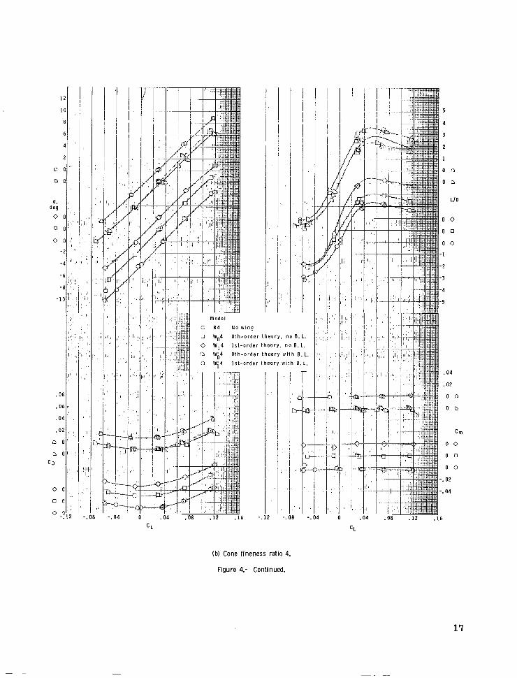
(b) Cone fineness ratio 4.
Figure 4.- Continued.
17
,
I
1 . 3
I D
I b
L I D
I C
I L
I "
1
2
3
4
5
.04
. 0 2
o r
o c
0 L\
0 0
0 L.
0 5
C m
. 0 2
. 0 4
.06
. oa
. I
Model
0 86 N o w i n g
:J w06 0 t h - o r d e r t h e o r y . no B . L.
0 w,6 1s t -o rde r t heo ry , no B. L.
c\ wM6 Empi r ica l n wb6 0 t h - o r d e r t h e o r y w i t h B. L .
c W:6 1 s t - o r d e r t h e o r y w i t h B.L.
I
. J.. .
I
. I 1
ri t
."I .
O 4 -.t O2 li 7 ' : 0
-
I I
1 ' !
4
-I '
I -4 " i ,r .04
" t C > 1
"P I . o
(c) Cone f ineness rat io 6.
Figure 4.- Concluded.
18
I
.16
.14
.12
.10
-~ L a = p
' 'b .08
.06
.04
.02
C o n e f i n e n e s s
r a t i o
0
0
.2 .6 .8 1.0 1.2 1.4 1.6 s - Sb
W
's- 'b
Figure 5.- Summary of wing-planform-area effects.
19

6
4
2
0 LID
(a) Empirical planform wings.
Figure 6.- Effect of fineness ratio on aerodynamic characteristics.
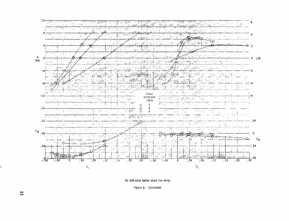
(bl Half-cone bodies alone (no wing).
Figure 6.- Concluded.

I
(a) Cone fineness ratio 2.
Figure 7.- Effect of wing leading-edge thickness and shape on aerodynamic characteristics.
L I D
0 4
0
cnl 04
08
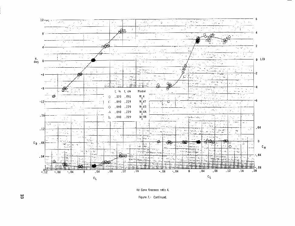
(b) Cone fineness ratio 4.
Figure 7.- Continued.

6
4
2
0 L / D
-2
- 4
. . t, in. t, cm M o d e l - - --- " - -. "" . *
I . . 1 - .
. t
- "" ~ __ ' -. . ". 0 . 0 2 0 . 0 5 1 Wi6 . .
0 ,090 . 2 2 9 W;6T . . . . i . . . . . . " , _ . .
" . .
(c) Cone fineness ratio 6.
Figure 7.- Concluded.
c

NATIONAL AERONAUTICS AND SPACE ADMINISTRATION WASHINGTON, D. C. 20546
OFFICIAL BUSINESS FIRST CLASS MAIL
NATIONAL AERONAUTICS AP POSTAGE A N D FEES PAID
SPACE ADMINISTRATION
POSThfASTER: If Undeliverable (Section 15E Postal Manual) Do Not Rerut
NASA SCIENTIFIC AND TECHNICAL PUBLICATIONS
TECHNICAL REPORTS: Scientific and TECHNICAL TRANSLATIONS: Information technical information considered important, pGblished in a foreign language considered complete, and a lasting contribution to existing to merit NASA distribution in English. knowledge. , .
TECHNICAL NOTES: Information less broad * ’ :1; derived from or of value to NASA activicies. in scope but nevertheless of importance as n ..: Publications include conference proceedings, contribution to existing knowledge. L. :. . monographs, data compilations, handbooks,
TECHNICAL MEMORANDUMS: ,
Information receiving limited distribution TECHNOLOGY UTILIZATION because of preliminary data, security classifica- ” PUBLICATIONS: Information on technology tion, or other reasons. used by NASA that may be of particular
interest in conmercial and other non-aerospace CONTRACTOR REPORTS: Scientific and npplications. Publications include Tech Briefs, technical information generated under a NASA Ttcl,nology and Notes, contract or grant and considered an important contribution to existing knowledge.
and Technology Surveys.
/
--‘SPECIAL PUBLICATIONS: Information
i. sourcebooks, and special bibliographies.
Details on the availability of these publications may be obtained from:
SCIENTIFIC AND TECHNICAL INFORMATION DIVISION
NATIONAL AERONAUTICS AND SPACE ADMINISTRATION Washington, D.C. 20546