NASA Reference Publication 1370 · 2013-08-30 · NASA Reference Publication 1370 1997 National...
62
NASA Reference Publication 1370 1997 National Aeronautics and S_3ace Administration Office of Management Scientific and Technical Information Program Training Manual for Elements of Interface Definition and Control Vincent R. Lalli Lewis Research Center Cleveland, Ohio Robert E. Kastner Vitro Corporation Rockville, Maryland Henry N. Hartt Vitro Corporation Washington, DC https://ntrs.nasa.gov/search.jsp?R=19970018043 2020-04-19T13:08:44+00:00Z
Transcript of NASA Reference Publication 1370 · 2013-08-30 · NASA Reference Publication 1370 1997 National...

NASA
Reference
Publication
1370
1997
National Aeronautics and
S_3ace Administration
Office of Management
Scientific and Technical
Information Program
Training Manual for Elements of InterfaceDefinition and Control
Vincent R. Lalli
Lewis Research Center
Cleveland, Ohio
Robert E. Kastner
Vitro Corporation
Rockville, Maryland
Henry N. Hartt
Vitro Corporation
Washington, DC
https://ntrs.nasa.gov/search.jsp?R=19970018043 2020-04-19T13:08:44+00:00Z


Preface
This technical manual was developed under the Office of Safety and Mission Assurance continuous
training initiative. The structured information contained in this manual will enable the reader to efficiently and
effectively identify and control the technical detail needed to ensure that flight system elements mate properlyduring assembly operations (both on the ground and in space).
Techniques used throughout the Federal Government to define and control technical interfaces for both
hardware and software were investigated. The proportion of technical information actually needed to
effectively define and control the essential dimensions and tolerances of system interfaces rarely exceeded 50
percent of any interface control document. Also, the current Government process for interface control is very
paper intensive. Streamlining this process can improve communication, provide significant cost savings, and
improve overall mission safety and assurance.
The primary thrust of this manual is to ensure that the format, information, and control of interfaces
between equipment are clear and understandable, containing only the information needed to guarantee
interface compatibility. The emphasis is on controlling the engineering design of the interface and not on the
functional performance requirements of the system or the internal workings of the interfacing equipment.
Interface control should take place, with rare exception, at the interfacing elements and no further.
There are two essential sections of the manual. The first, Principles of Interface Control, discusses how
interfaces are defined. It describes the types of interface to be considered and recommends a format for the
documentation necessary for adequate interface control. The second, The Process: Through the Design Phases,provides tailored guidance for interface definition and control.
This manual can be used to improve planned or existing interface control processes during system design
and development. It can also be used to refresh and update the corporate knowledge base. The information
presented herein will reduce the amount of paper and data required in interface definition and control processesby as much as 50 percent and will shorten the time required to prepare an interface control document. It also
highlights the essential technical parameters that ensure that flight subsystems will indeed fit together and
function as intended after assembly and checkout.
iii

Acknowledgments
In 1992 the NASA Reliability and Maintainability Steering Committee recognized the need to provide its
engineers, especially its design engineers, with a practical understanding of the principles and applications ofinterface definition and control documentation. A working group was formed and met at Goddard Space Flight
Center to discuss how some of the NASA centers were handling this topic. Four centers and NASA Headquarters
participated in the meeting: Headquarters--NASA handbook methods; Johnson Space Center (JSC) andMarshall Space Flight Center (MSFC)--space station; Lewis Research Center--space station and launch
vehicles; Jet Propulsion Laboratory (JPL)--Mars Observer; and Goddard Space Flight Center (GSFC)--space
experiments.To satisfy the need for a short, informative interface definition and control training manual, Robert E.
Kastner and Henry N. Hartt of the Vitro Corporation prepared the manual using material from the working
group meeting. Harvey L. Schabes and William J. Taylor of Lewis Research Center served as the final
NASA project office reviewers. Their suggestions improved the usefulness of the text for flight projects. Thededication, time, and technical contributions of Jack Remez/GSFC; Donald Bush (retired)/MSFC; David
Oberhettinger/SYSCON (JPL); Daniel Deans/LORAL (JSC); and Ronald Lisk/NASA Headquarters (Code Q)
in the preparation of this manual are appreciated. Without the support of their individual centers and their
enthusiastic personal support and willingness to serve on the NASA Reliability and Maintainability SteeringCommittee, this manual would not have been possible.
The following NASA members of the steering committee may be contacted for more information about the
processes and products discussed in this manual:
James F. Clawson
Jet Propulsion Laboratory
California Institute of Technology
MS 301-456, SEC 505
4800 Oak Grove Drive
Pasadena, CA 91109
Office: (818) 354-7021
Facsimile: (818) 393-4699
E-mail: james, f.clawson @ccmail.jpl.nasa.gov
John Greco
NASA Langley Research Center
MS 421, Bldg. 1162A, Rm. 125
5A Hunsaker Loop
Hampton, VA 23681--0001
Office: (804) 864-3018
Facsimile: (804) 864-6327
E-mail: j.a.greco @ larc.nasa.gov
Wilson Harkins
NASA Headquarters, Code QS
300 E. Street SW
Washington, DC 20546
Office: (202) 358--0584
Facsimile: (202) 358-3104
E-mail: wharkins @ cc.hq.nasa.gov
Vincent R. Lalli
NASA Lewis Research Center
Code 0152, MS 501-4
Cleveland, OH 44135
Office: (216) 433-2354
Facsimile: (216) 433-5270
E-mail: rqlalli @ lims01 .terc.nasa.gov
Michael E. Langley
NASA George C. Marshall Space Flight Center
CR-10, Bldg. 4203
Marshall Space Flight Center, AL 35812
Office: (205) 544-0056
Facsimile: (205) 544-4155
E-mail: michael.langley @ ms fc.nasa.gov
Dan Y. Lee
NASA Ames Research Center
MS 240A-3, P.O. Box 1000
Moffet Field, CA 94035-1000
Office: (415) 604-5962
Facsimile: (415) 6044)399
E-mail: dan lee @qmgate.arc.nasa.gov
iv

LeonR.MigdalskiNASAKennedySpaceCenter
RT-SRD-2 OSB3309
Kennedy Space Center, FL 32899
Office: (407) 861-3284
Facsimile: (407) 861-4314
E-mail: lmigdals @ srqa.ksc.nasa.gov
Jack W. Remez
NASA Goddard Space Flight Center
Code 302, Bldg. 6, Rm. $240
Greenbelt, MD 20771
Telephone: (301) 286-7113
Facsimile: (301) 286-1701
E-mail: remez @gsfc.nasa.gov
Donald L. Wiley
NASA Lyndon B. Johnson Space Center
Code NS3, Bldg. 45, Rm. 616B
Houston, TX 77058
Office: (713) 483---4084
Facsimile: (713) 483-3045
E-mail: dwiley @gp 101.jsc.nasa.gov

Contents
Chapter1. Introduction ........................................................................ 1
1.1 Training ........................................................................ 2
2. Principles of Interface Control ......................................................... 3
2.1 Purpose of Interface Control ........................................................ 32.2 Identifying Interfaces .............................................................. 3
2.3 Categorizing (Partitioning) and Defining Interfaces ...................................... 42.3.1 Electrical/Functional ......................................................... 4
2.3.2 Mechanical/Physical .......................................................... 42.3.3 Software ................................................................... 5
2.3.4 Supplied Services ............................................................ 5
2.4 Documenting Interfaces ............................................................ 6
2.5 Identifying Steady-State and Non-Steady-State Interfaces ................................. 6
2.6 Selecting a Custodian .............................................................. 6
2.7 Analyzing for Interface Compatibility ................................................. 72.8 Verifying Design Compliance With Interface Control Requirement .......................... 7
2.9 Verifying Contract-Deliverable Item .................................................. 7
2.10 Training ........................................................................ 8
3. The Process: Through the Design Phases .............................................. 13
3.1 Program Phases ................................................................. 13
3.1.1 Concept Definition .......................................................... 13
3.1.2 Requirements Definition ..................................................... 13
3.1.3 Systems Integration ......................................................... 163.2 Preparing and Administering Interface Control Document ................................ 16
3.2.1 Selecting Types of Interface Control Document ................................... 16
3.2.2 Tracking and Resolving Missing Interface Design Data ............................. 163.3 Initial Issuance of ICD ............................................................ 17
3.4 Document Review and Comment ................................................... 17
3.4.1 Resolving Comments ........................................................ 17
3.4.2 Interface Control Working Group .............................................. 17
3.4.3 Approval/Signoff Cycle ...................................................... 19
3.4.4 Technical Approval ......................................................... 193.4.5 Baselining ................................................................. 19
3.5 Change Notices ................................................................. 193.5.1 Initiating Changes .......................................................... 19
3.5.2 Requesting Changes ......................................................... 2 I
3.5.3 Proposed Change Notice Review and Comment Cycle .............................. 213.5.4 Processing Approved Changes ................................................. 21
3.5.5 Distributing Approved Changes ................................................ 21
3.5.6 Configuration Control Board .................................................. 21
3.5.7 Closing the Loop ........................................................... 22
3.6 Training ....................................................................... 22
vi

Appendixes:A: Electrical/Functional Interface Example .............................................. 24B: Mechanical/Physical Interface Examples .............................................. 29
C: Software Interface Example ........................................................ 38
D: Supplied Services Interface Example ................................................. 39
E: Compatibility Analysis ............................................................ 43
F: Bracket System for Interfaces ....................................................... 46G: ICD Guidelines .................................................................. 48
H: Glossary ....................................................................... 49
References ........................................................................... 50
Bibliography .......................................................................... 50
Training Answers ...................................................................... 51
vii


Chapter I
Introduction
This technical manual resulted from an investigation of
techniques used throughout NASA and other Federal Govern-
ment agencies to define and control technical interfaces for
both hardware and software. The processes described herein
distill the requirements for interface definition and control into
a concise set of parameters that control the design of only the
interface-related elements rather than providing extraneous
design detail that must subsequently be configurationmanaged.
The purpose of this manual is to provide guidelines for
establishing and conducting the interface control process so
that items produced by different design agencies satisfactorily
mate and operate in a way that meets mission requirements.
These guidelines were drawn from the methodologies of a
number of highly successful programs and therefore represent
a compilation of "lessons learned."
The principles and processes of interface definition and
control presented in this document apply to all projects and
programs but may be tailored for program complexity. For
example, the interface control process may be less formal for a
project or program that requires only one or two end items and
has few participants; however, the formal interface control
document is still necessary. For a project or program that
requires a number of end items and where several participants
are involved, a carefully followed interface control process is
imperative, with comments, decisions, agreements, and com-
mitments fully documented and tracked. Individual managersshould provide the implementation criteria for their interface
control processes early in the project or program (ref. 1).
This manual covers the basic principles of interface defini-
tion and control: how to begin an interface control program
during the development of a new project or program, how to
develop and produce interface dc :umentation, how to manage
the interface control process, and how to transfer interface
control requirements to hardware and software design.
Interface definition and control is an integral part of system
engineering. It should enter the system engineering cycle at the
end of the concept development phase. Depending on whether
the system under development is designed for one-time or
continuous use, the process may continue for the full life cycleof the system. Interface definition and control should not be
equated to configuration management or configuration control.Rather it is a technical management tool that ensures that all
equipment will mate properly the first time and will continue to
operate together as changes are made during the life cycle of the
system. Figure 1.1 depicts the elements of the system engineer-
ing cycle and is used in chapter 3 to describe the application of
the interface discipline at different parts of the life cycle (ref. 2).
Establishing a system that ensures that all interface param-
eters are identified and controlled from the initial design
activities of a program is essential. It is not necessary that the
fine details of these parameters be known at that time, but it is
very important that the parameters themselves are identified,that everything known about them at that time is recorded andcontrolled, and that voids I are identified and scheduled for
elimination. The latter requirement is of primary importance to
the proper design of any interface. Initial bounding of a void and
scheduled tightening of those bounds until the precise dimen-
sions or conditions are identified act as a catalyst to efficient
design and development. An enforced schedule for eliminating
voids is one of the strongest controls on schedule that can be
applied (ref. 3).
The process of identifying, categorizing, defining, and docu-
menting interfaces is discussed in the following chapter. Guid-
ance for the analysis of interface compatibility is also provided.
Verification _ Mission needsand validation I definition
_Risk and
Technical /_ ] /_ syste_is
C::fie_ __c_ip_ Jn
in;egr_fion_ee_iu_r_:ents
Figure 1,1--System engineerig cycle. (Therequirements definition phase must includethe requirements for the interfaces as well asthose which will eventually be reflected in theinterface control document,)
1A "void" is a specific lack of information neededfor control of an interfacefeature. Control and elimination of voids is fundamental to a strong interfacedefinition and control program.

1.1 Training 2
1. The processes explained in this manual for interfacedefinition and control are
A. A concise set of parameters that control the design of theinterface-related elements
B. A set of design details needed for configuration manage-ment
2. The process is very important for projects that requireA. A number of end items
B. Involvement of several participants
C. Comments, decisions, agreements, and commitments
that must be fully documented and trackedD. All of the above
3. What elements does the system engineering cycle contain?
A. Mission needs, requirements, and integration
B. Technical oversight, core design, and system configura-tion
C. Mission needs definition, risk and systems analysis,
concept and requirements definitions, system integra-
tion, configuration management, technical oversight,and verification and validation
4a. What is a void?A. Bracketed data
B. Wrong dataC. Lack of information needed
4b. How should voids be handled?
A. Voids should be identified and their elimination
scheduled.
B. Data should be analyzed.
C. Supplier should be guided.
4c. Name a strong control needed for voids.A. Precise dimensions
B. Enforced schedule
C. Identified catalysts
2Answers are given at the end of this manual.

Chapter 2
Principles of Interface Control
2.1 Purpose of Interface Control
An interface is that design feature of a piece of equipment 3
that affects the design feature of another piece of equipment.
The purpose of interface control is to define interface require-
ments so as to ensure compatibility between interrelated pieces
of equipment and to provide an authoritative means of control-
ling the design of interfaces. Interface design is controlled by an
interface control document (ICD).These documents
1. Control the interface design of the equipment to prevent
any changes to characteristics that would affect compat-
ibility with other equipment
2. Define and illustrate physical and functional characteris-
tics of a piece of equipment in sufficient detail to ensure
compatibility of the interface, so that this compatibilitycan be determined from the information in the ICD alone
3. Identify missing interface data and control the submis-sion of these data
4. Communicate coordinated design decisions and design
changes to program participants
5. Identify the source of the interface component
ICD's by nature are requirements documents: they define
design requirements and allow integration. They can cause
designs to be the way they are. They record the agreed-to design
solution to interface requirements and provide a control mecha-
nism to ensure that the agreed-to designs are not changed by oneparticipant without negotiated agreement of the other participant.
To be effective, ICD's should track a schedule path compat-
ible with design maturation of a project (i.e., initial ICD's
should be at the 80% level of detail at preliminary design
review, should mature as the design matures, and should reach
the 99% mark near the critical design review).
2.2 Identifying Interfaces
Identifying where interfaces are going to occur is a part of
systems engineering that translates a mission need into a
configured system (a grouping of functional areas) to meet that
need. Each functional area grouping is assigned certain peffor-
mance requirements. These performance requirements are trans-
lated into design requirements as the result of parametric
studies, tradeoff studies, and design analyses. The design
requirements are the basis for developing the system specifica-tions. The boundaries between the functional areas as defined
in the system specifications become the interfaces. Early inter-
face discussions often contribute to final subsystem specifica-
tions. Interface characteristics, however, can extend beyond the
interface boundary, or interface plane, where the functionalareas actually come together. The interface could be affected
by, and therefore needs to be compatible with, areas that
contribute to its function but may not physically attach. For
example, it may be necessary to define the path of a piece of
equipment as it traverses through another piece of equipment
and rotates and articulates to carry out its function. Electrical
characteristics of a transmitter and receiver separated by an
interface plane may have to be defined for each to properly
function. Similarly, the acoustic energy produced by one com-
ponent and transmitted through the structure or onto another
component may need a corresponding definition.
Identifying interfaces early in a program is essential tosuccessful and timely development. Functional analyses are
used for analyzing performance requirements and decompos-ing them into discrete tasks or activities (i.e., decomposing the
primary system functions into subfunctions at ever increasing
levels of detail). Functional block diagrams are used to define
data flow throughout the system and interfaces within the
system. Once the segments and elements within a system have
been defined, a top-level functional block diagram is prepared.
The block diagrams are then used in conjunction with N-
squared diagrams to develop interface data flows. The N-
squared diagram is a technique used extensively to develop data
interfaces but can also be refined for use in defining hardwareinterfaces. However, use of this tool in this manual will be
restricted to interface categorization. Additional description is
provided in section 3.1.1.In summary, identifying where interfaces are going to occur
begins the systems integration component of systems engineer-
ing and must start early in design planning. The interface
boundaries or planes vary from program to program depending
on how design and development responsibilities are assigned.Interface control can occur within a functional area of other
design and development agents. Therefore, interfaces can be
identified at many levels, for example,
3Forpurposesof this manual,a pieceof equipment isa functional areaassignedto a specific source. Thus, a piece of equipment can be an elementof the spacestation, a systemof a spacecraft, a work packageassigned to a contractor, or asubsystem.
1. Center to center
2. Discipline to discipline (e.g., propulsion to guidance,
sensor to structure, or power to users)3. Contractor to contractor

4. Centertocontractor to discipline
5. Program to program (e.g., shuttle to National Launch
System)
Once interface boundaries or planes are established, the
interfaces must be categorized and defined.
2.3 Categorizing (Partitioning) and
Defining Interfaces
Categorizing, or partitioning, interfaces separates the inter-
face features by technical discipline and allows each category,
in most cases, to proceed through the definition process
independently.The following basic interface categories (defined by the
types of feature and data they encompass) are recommended for
use in most programs:
1. Electrical/functional
2. Mechanical/physical3. Software
4. Supplied services
During the early phases of systems engineering, interfaces
may be assigned only the high-level designation of these
categories. As the system becomes better defined, the details ofthe physical and functional interface characteristics becomebetter defined and are documented.
An interface can be assigned to one of these categories by a
number of processes of elimination. The one recommended for
use is the N-squared diagram (ref. 4), which is currently being
used by some NASA centers.
2.3.1 Electrical/Functional
Electrical/functional interfaces are used to define and con-
trol the interdependence of two or more pieces of equipment
when the interdependence arises from the transmission of an
electrical signal from one piece of equipment to another. All
electrical and functional characteristics, parameters, and toler-
ances of one equipment design that affect another design are
controlled by the electrical/functional ICD. The functionalmechanizations of the source and receiver of the interface
electrical signal are defined, as well as the transmissionmedium.
The interface definition includes the data and/or control
functions and the way in which these functions are represented
by electrical signals. Specific types of data to be defined arelisted here:
1. Function name and symbol
2. Impedance characteristics
3. Shielding and grounding
4. Signal characteristics5. Cable characteristics
6. Data definition
7. Data transmission format, coding, timing, and updating8. Transfer characteristics
9. Circuit logic characteristics
10. Electromagnetic interference requirements11. Data transmission losses
12. Circuit protective devices
Other data types may be needed. For example, an analog
signal interface document would contain function name and
symbol, cable characteristics, transfer characteristics, circuit
protective devices, shielding, and grounding; whereas a digital
data interface would contain function name and symbol, data
format, coding, timing and updating, and data definition.
Additional data types under the electrical/functional headingare
1. Transmission and receipt of an electrical/electromag-
netic signal2. Use of an electrically conductive or electromagnetic
medium
Appendix A shows recommended formats for electrical andfunctional interface control drawings.
2.3.2 Mechanical/Physical
Mechanical/physical interfaces are used to define and con-trol the mechanical features, characteristics, dimensions, and
tolerances of one equipment design that affect the design of
another subsystem. They also define force transmission re-
quirements where a static or dynamic force exists. The featuresof the equipment that influence or control force transmissionare also defined in this ICD. Mechanical interfaces include
those material properties of the equipment that can affect the
functioning of mating equipment, such as thermal and galvanic
characteristics. Specific types of data defined are
1. Optical characteristics
2. Parallelism and straightness
3. Orientation requirements
4. Space or provisions required to obtain access for perform-
ing maintenance and removing or replacing items, in-
cluding space for the person performing the function5. Size, shape, mass, mass distribution, andcenter of gravity
6. Service ports
7. Indexing provisions
8. Concentricity9. Surface finish
10. Hard points for handling

11.Sealing,pressurization,attachment,andlockingprovisions
12.Locationandalignmentrequirementswithrespecttootherequipment
13.Thermalconductivityandexpansioncharacteristics14.Mechanicalcharacteristics(springrate,elasticproper-
ties,creep,set,etc.)15.Load-carryingcapability16.Galvanicandcorrosivepropertiesof interfacing
materials
Otherdatatypesmaybeneeded.Forexample,anICDcontrollingaform-and-fitinterfacewouldgenerallycontainsuchcharacteristicsassizeandshapeof theitem,locationofattachmentfeatures,locationofindexingprovisions,andweightandcenterofgravityoftheitem.However,anICDcontrollingastructuralloadinterfacewouldcontainweightandcenterofgravity,load-carryingcapability,andelasticpropertiesofthematerialif applicabletotheloadingconditions.NotallICD'scontrollingaform-and-fitinterfacewouldhavetocontainalltypesof datagivenin thisexample,butsomeform-and-fitinterfacedefinitionscontainmorethanthe16typesof datalisted.Indexingdefinitionsmayrequireangularity,waviness,andcontourdefinitionsandtolerances.
Additionaldatatypesunderthemechanical/physicalhead-ingwouldbe
1.Dimensionalrelationshipsbetweenmatingequipment2.Force transmission across an interface
3. Use of mechanically conductive media
4. Placing, retaining, positioning, or physically transporting
a component by another component
5. Shock mitigation to protect another component
Appendix B (from ref. 5) shows a mechanical/physical draw-
ing.
This extensive variety of possibilities and combinations
prevents assigning a standard set of data types or level of detail
to a form-and-fit interface. Each interface must be analyzed and
the necessary controlling data identified before the proper levelof interface definition and control can be achieved. This holds
true for all examples given in this chapter.
2.3.3 Software
A software interface defines the actions required when
interfacing components that result from an interchange of
information. A software interface may exist where there is nodirect electrical interface or mechanical interface between two
elements. For example, whereas an electrical ICD might define
the characteristics of a digital data bus and the protocols usedto transmit data, a software interface would define the actions
taken to process the data and return the results of the process.
Software interfaces include operational sequences that involve
multiple components, such as data-processing interactions
between components, timing, priority interrupts, and watchdog
timers. Controversy generally arises in determining whether
these relationships are best documented in an electrical/func-
tional ICD, a software ICD, or a performance requirements
document. Generally, software interface definitions include
1. Interface communication protocol
2. Digital signal characteristics
3. Data transmission format, coding, timing, and updating
requirements4. Data and data element definition
5. Message structure and flow
6. Operational sequence of events7. Error detection and recovery procedures
Other data types may be needed. Appendix C provides an
example of a software interface signal.
2.3.4 Supplied Services
Supplied services are those support requirements that a piece
of equipment needs to function. Supplied services are provided
by an external separate source. This category of interface can be
subdivided further into electrical power, communication, fluid,
and environmental requirements. The types of data defined forthese subcategories are
1. Electrical power interface:a. Phase
b. Frequency
c. Voltage
d. Continuity
e. Interrupt timef. Load current
g. Demand factors for significant variations during
operationsh. Power factor
i. Regulation
j. Rippleh. Harmonics
I. Spikes or transientsm. Ground isolation
n. Switching, standby, and casualty provisions2. Communication interface:
a. Types of communication required between equip-ment
b. Number of communication stations per communica-tion circuit
c. Location of communication stations
3. Fluid interface:
a. Type of fluid requiredi. Gaseous
ii. Liquid

b. Fluidpropertiesi. Pressureii. Temperatureiii. Flow rate
iv. Purityv. Duty cycle
vi. Thermal control required (e.g., fluid heat lost or
gained)4. Environmental characteristic interface:
a. Ambient temperature
b. Atmospheric pressure
c. Humidity
d. Gaseous composition required
e. Allowable foreign particle contents
Other data types may be needed. Appendix D shows an ex-
ample of a supplied services interface for air-conditioning and
cooling water.
2.4 Documenting Interfaces
Once an interface has been categorized and its initial con-tents defined, that interface definition must be recorded in a
document that is technically approved by the parties (designer
and manager) and the owners of both sides of the interface. The
document then is approved by the next higher level in the
project management structure and becomes the official control
for interface design.The program manager must ensure that compliance with the
approved interface control document is mandatory. Each level
of program management must ensure that the appropriatecontractors and Government agencies comply with the docu-
mentation. Therefore, technical approval of the interface con-trol document indicates that the designated approving
organization is ready to invoke the interface control document
contractually on the approving organization's contractor or
supporting organization.The interface categories can be grouped together in one
document, or each category can be presented in a separate
document (i.e., electrical ICD's, mechanical ICD's, etc). Theformat for interface control documents is flexible. In most cases
a drawing format is the easiest to understand and is adaptableto the full range of interface data.
The specification format (ref. 6) can also be used. The use of
this type of format enables simple changes through the removal
and insertion of pages; however, the format is often difficult to
use when presenting complex interface definitions that require
drawings, and normally requires many more pages to conveythe same level of information.
In either case there must be agreement on a standard for data
presentation and interpretation. ANSI standard Yl 4.5 (ref. 7)can be used for dimensions, along with DOD-STD-100
(ref. 8), for general guidance of a drawing format. The specifi-cation format should use MIL-STD-490 (ref. 6) for paragraph
numbering and general content.
Some large programs require large, detailed ICD's. Main-
taining a large, overly detailed document among multiple
parties may be more difficult than maintaining a number ofsmaller, more focused documents. Grouping small documents
by major category of interface and common participants is oneof the most effective and efficient strategies. It minimizes the
number of parties involved and focuses the technical disci-
plines, greatly streamlining the decision process and permitting
much shorter preparation time. However, interfaces can be
multidisciplinary and separate documents can result in mis-communications.
2.5 Identifying Steady-State and
Non-Steady-State Interfaces
Interfaces can vary from a single set that remains constant for
the life of a program to a multiple set of documents that
reconfigures during specific events in the life of a system. The
first category would be used for an interplanetary probe. The
interfaces of its instruments with the basic spacecraft structure
would remain the same from assembly for launch throughout
the life of the experiment. However, a continually evolving
platform, such as a lunar base, would perhaps be controlled ina series of interface documents based on the assembly sequenceof the base. An initial base would be established and later made
more complex with additional structures and equipment deliv-
ered by subsequent lunar flights. Pressurized elements, logistic
elements, power-generating sources, habitats, laboratories, and
mining and manufacturing facilities might be added and
reconfigured over time. Each configuration would require a setof interface control documents to ensure compatibility at theconstruction site as well as with the transportation medium
from Earth to Moon. Interfaces that remained constant during
this process might be termed steady state and require no furtherconsideration once the interface was verified and delivered;whereas interfaces that would evolve from the initial
configuration through multiple iterations would require multi-coordination of interface parameters and schedules. The selec-
tion of interface categories should identify the steady-state or
non-steady-state nature of interfaces as well as their initial
designations (ref. 9).
2.6 Selecting a Custodian
Selecting an ICD custodian can depend on several factors
(e.g., percentage of interface ownership, relative mission im-portance of interface sides, and relative investment of interface
sides). However, it is generally most effective if the custodian

selectedhasanobjectivepointof view.Anexampleof thiswouldbesomeonewhois independentofeithersideof theinterface(i.e.,withoutany"vestedinterest"in theinterfacehardwareorsoftware).Objectivitypermitsunbiasedcontroloftheinterface,involvementof thecustodianasanobjectivemediator,anddocumentationoftheinterfaceonanoninterfer-encebasiswithprogram/projectinternaldesign.Selectinganindependentinterfacecustodianshouldbethefirststepinestablishinganinterfacecontrolorganization.Asetofcriteriashouldbeusedtoselectthecustodianbyweightingthecontentandinterestsoftheinterfacewiththeneedsofinterfacecontrol.Onesetofcriteriaisasfollows:
1. Integration center: Is one center accountable for integrat-
ing the interfaces controlled by this ICD? This criterion is
considered the most important because the integration center
will have the final responsibility for certifying flight readinessof the interfaces controlled in the ICD.
2. U.S. center: Is the participant a U.S. center? This crite-
rion is considered the next most important because of agency
experience and projected responsibility.
3. Flight hardware or software: Is the interfacing articleflight hardware or software (as opposed to support hardware or
software)? Flight hardware or software takes precedence.
4. Flight sequence: Does one side of the interfacing equip-
ment fly on an earlier manifest than the other? An earlier flight
sequence takes precedence over follow-on interfacinghardware.
5. Host or user: Is the interfacing article a facility (as
opposed to the user of the facility)? Procedure in this criterion
is guided by the relative priority of the interfacing articles.
6. Complexity: How complex is the interfacing equipment
(relative to each side)? The more complex side of the interfacenormally takes precedence.
7. Behavior: How active is the interfacing equipment? The
active side normally takes precedence over the passive side.8. Partitions: How are the partitions (categories) used by the
interfacing equipment? The relative importance of the parti-
tions to the interface is acknowledged, and selection of the
custodian is sensitive to the most important partition
developers.
Scores are assigned to each piece of interfacing equipment
for each criterion. These scores can be determined by many
different methods. Discrete values can be assigned to the first
four criteria. A score of 1.0 is assigned if the interfacing piece
of equipment is unique in meeting the criterion, the other piece
of equipment then receives a score of 0.0. Scores of 0.5 areassigned to both sides if both (or neither) of them meet the
criterion. There is no definitive way of assigning scores to thelast four criteria; however, verbal consensus or an unbiased
survey can be used to assign scores. Also, the partition criteria
can be scored by partition evaluation analysis (ref. 4).
2.7 Analyzing for Interface
Compatibility
The interface definitions to be documented on the ICD's
must be analyzed for compatibility before the ICD is authenti-
cated. Appendix E provides guidance on how compatibility
analyses may be performed. They vary in their complexity from
a simple inspection of the interface definitions to complex
mathematical analyses where many variables are involved.
Regardless of complexity, the compatibility analysis should
be documented and maintained as backup information for the
ICD. It can be used to expedite any changes to the interface
definition by providing a ready means for evaluating the
compatibility of the proposed change. The compatibility analy-sis also can be used to document how the interface definition
was arrived at and why the definition is presented as it is onan ICD.
2.8 Verifying Design Compliance With
Interface Control Requirement
The ICD can only fulfill its purpose if the contractors'
detailed design drawings and construction practices adhere to
the limits imposed by the ICD. Verifying compliance of the
design as well as of the construction process is an integral partof interface control.
Each contractor should be assigned the responsibility of
denoting on their manufacturing and inspection drawings ordocuments those features and characteristics that, if altered,
would affect interfaces controlled by the ICD's. To ensure thatall ICD requirements are covered, the contractor should select,
at the highest assembly level at which the equipment is in-
spected, the features and characteristics to be denoted. Anydesign change affecting an ICD-controlled feature or charac-
teristic would be clearly identified even at the assembly level
(ref. 10).
Entries identified as "to be resolved" (TBR) can be bracketed
or shaded to indicate preliminary interface information or an
interface problem. This information is subject to further review
and discussion and is an interim value for use in evaluatingeffects. Entries identified as "to be supplied" (TBS) represent
data or requirements to be furnished. Appendix F shows a
typical bracket system.
2.9 Verifying Contract-Deliverable Item
Each contract-deliverable item that is a mating side to an ICD
interface should also be tested or measured to verify that the
item complies with the requirement as specified in the ICD. The

responsibilityforadministeringandreportingonthisverifica-tionprogramcouldbeassignedtothedesignagent,thecontrac-tor,oranindependentthirdparty.If feasible,anindependentthirdpartyshouldbeselectedforobjectivity.
Theverificationmethodsshouldincludeanalysis,measure-mentandinspection,demonstration,andfunctionaltesting.Thespecificmethodsemployedateachinterfacewilldependonthetypeoffeatureandtheproductionsequence.Complianceshouldbeverifiedatthehighestpracticalassemblylevel.Toprecludefabricationbeyondthepointwhereverificationcanbeperformed,anintegratedinspection,measurement,anddem-onstrationtestoutlineofbothhardwareandsoftwareshouldbedeveloped.Thisverificationtestoutlinewillprovideasched-ule,tiedtoproduction,thatallowsallinterfacerequirementstobeverified.Theresultantdataandinspectionsheetsshouldbecomepartof theverificationdatain thehistoryjacketretainedbythecontractorforNASA.
2.10 Training 2
l, What is the purpose of interface control?A. To define interfaces
B. To ensure compatibility between interrelated equip-ment
C. To provide an authority to control interface designD. All of the above
2. How is an interface identified?
A. By boundaries between functional areas
B. By functional analyses of performance requirements
C. By design features of a component that can affect the
design features of another component
3a. How can interfaces be categorized?A. Mechanical, electrical, software, and services
B. Electrical/functional, mechanical/physical, software,
and supplied services
C. Electrical, physical, software, and supplies
3b. What is one method of assigning an interface to one of the
four basic categories?A. Functional flow block diagram
B. Timeline analysis
C. N-squared diagram
4a. How can an interface be documented?
A. By drawing format
B. By specification format
C. By both of the above
4b. Who approves the interface control document?
A. Designer or managerB. Owners of both sides
C. Both of the above
4C. Who ensures compliance with the approved ICD?
A. Designer or managerB. Owners of both sides
C. Project manager
5a. What is a steady-state interface?
A. A single set that remains constant for the life of the
project
B. A multiple-set suite that reconfigures during specificevents in the life of the system
5b. Give an example of a steady-state interface.
A. An interplanetary probeB. A lunar base
5C. What features make this a good example of a steady-stateinterface?
A. The basic structure of the spacecraft would remain the
same from assembly for launch throughout the life of
the experiment.B. An initial base would be established and subsequently
made more complex with additional structures and
equipment delivered by subsequent lunar flights.
6a. How should an ICD custodian be selected?
A. Percentage of ownership of the interfaceB. Relative investment of interface sides
C. An objective point of view
6b. What criteria should be used to select a custodian?
A. Integration or U.S. center, flight hardware or software,
flight sequence, host or user, complexity, behavior,
and partitions
B. Integration hardware, sequence user, and partitions
6c. What scoring system can be used for these criteria?A. Zero to 1.0, verbal consensus, unbiased survey, and
partition evaluation analysis
B. One to 100, priority ranking, and voting
7a. What is the purpose of an ICD compatibility analysis?
A. Demonstrates definitions and provides mathematical
analysisB. Demonstrates completeness of an interface definition
and provides a record that the interface has been
examined and found to be compatible
2Answers are given at the end of this manual.

7b. What are the four categories that require interfaceanalysis?
A. Electrical/functional, mechanical/physical, supplied/
services, and hydraulic/pneumatic
B. Electrical/functional, mechanical/physical, software,
and supplied services
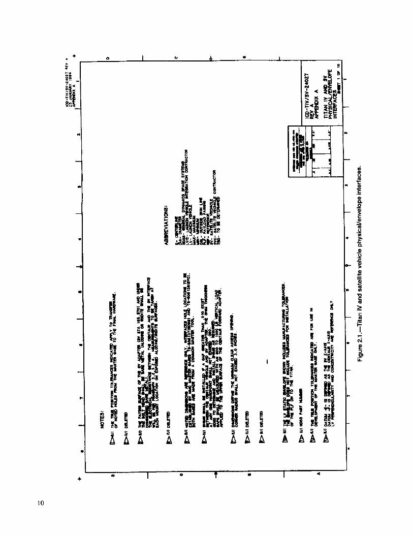
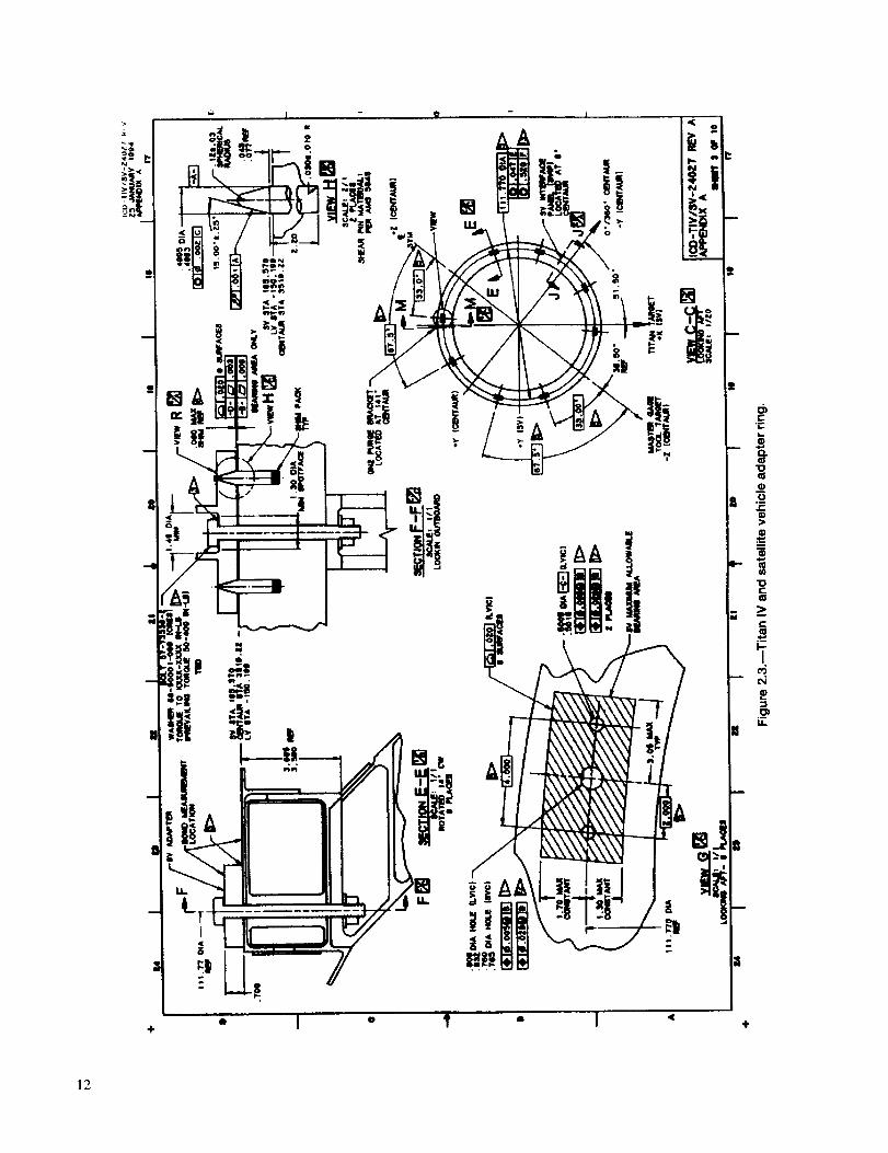
7c. The hardware for mounting the satellite vehicle (SV)
adapter to the Titan IV Centaur is shown in figures 2.1to 2.3.
A. Is there sufficient data to perform a compatibility
analysis?i. Yes ii. No
B. Can the Jet Propulsion Laboratory specify the SV
adapter ring?i. Yes ii. No
C. What items need to be bracketed?
i. Shear pin material and SV attachment view
ii. SV panel and view C-C
8a. What does a bracket on an ICD represent?
A. Verification of design compliance
B. An interface problem
8b. What interface deficiency rating does a bracket discrep-ancy have?
A. S & MA impact A > 1 or understanding of risk B > 2
B. S & MA impact A < 1 or understanding of risk B < 2
9a. How are mating sides of an ICD interface verified?
A. Testing or measurement to meet requirements
B. Analysis, measurement or inspection, demonstration,
and functional testing
9b. What does the verification test outline provide?
A. Schedule, tied to production, that allows interface
requirements to be verified
B. Process controls, tied to manufacturing, for meetingschedules
9c. Where is the resultant test and inspection data stored?
A. Contractor files for use by an independent third partyB. History jackets for use by NASA
9
iii-
+o T o T - "I '_
p
N
@
,t,,-,
10

0
Ill
Q
el
+
4{ 0
r,- 011k
° I ° i - I •
"8
"6
E
]l
÷o I 0 'Ii " I < ,41"
]2

Chapter 3
The Process: Through the Design Phases
Interface control should be started when a program begins.
This process eventually will define all interface design and
documentation responsibilities throughout the life cycle of theprogram. Each program phase from concept development to
project construction is directly related to the maturity level ofinterface control.
3.1 Program Phases
3.1.1 Concept Definition
During the system engineering concept definition phase
(from fig. 1.1), basic functional areas of responsibility areassigned for the various pieces of equipment that will be
employed by the project (electrical power, environment con-
trol, propulsion, etc.); see figure 3.1. At this point the design
responsibilities of the responsible organization and related
contractor (if chosen) should be defined to establish a set of
tiered, traceable requirements. From these requirements the
interfaces to be designed are identified by category (electrical/
functional, mechanical/physical, software, and supplied ser-
vices) and by type of data that must be defined. This categori-
zation will include a detailed review of each requirement to
determine which requirements or features will be controlled by
the interface control process. (What is important for this item to
fulfill its intended function? On what interfacing equipment isthis function dependent?) Once the interfaces to be controlled
are selected, the formal procedures for interface control need to
be established. These procedures include identifying the par-
definition
• Assign basic functional areas of responsibility.
• Define design responsibilities.
• Categorize interfaces.
• Define interfaces to be controlled.
• Establish formal interface control procedures.
• Disseminate scheme, framework, traceability.
Figure 3.1.BEstablishment of interface controlprocess during concept definition.
ticipants responsible for the interface control documentation,
the approval or signoff loop for documentation, and the degree
to which all participants have to adhere to interface control
parameters and establishing a missing design data matrix,change procedures, etc. (See section 3.2.)
Early development of the interface process, products, and
participants provides a firm foundation for the design engineer
to use the correct information in designing his or her portion of
an interface. It minimizes the amount of paper to be reviewed,shortens the schedule, and concentrates the efforts of the
designer on his or her area of responsibility.
Initial selection of interfaces generally begins with listing of
all pieces of equipment in a system and then identifying the
extent of interrelation among them. One tool used to help in this
process is the N-squared diagram. Details of this process can be
found in reference 4. The N-squared diagram was initially used
for software data interfacing; however, some centers are using
it for hardware interfaces. If the diagram is not polarized
initially (input/output characteristics not labeled), it is a conve-
nient format for identifying equipment interfaces and for cat-
egorizing them. An example of this form is shown in figure 3.2.This diagram can be further stratified to identify the interfaces
for each of the categories; however, detailed stratification is
best applied to electrical/functional, software, and supplied
services interfaces. Using the N-squared diagram permits an
orderly identification and categorization of interfaces that can
be easily shown graphically and managed by computer.
By the end of this phase the basic responsibilities and
management scheme, the framework for the interface control
documentation, and the process for tracking missing interfacedesign data (see section 3.2.2) should be established anddisseminated.
3.1.2 Requirements Defmition
During the requirements definition phase (fig. 3.3; from
fig. 1. I), the definitions of the mission objectives are completed
so that each subsystem design can progress to development.
Here, the technology to be used in the project will be defined to
limit the risk associated with the use of new, potentially
unproven technologies. Defining requirements and baselining
interface documents early in the design process provides infor-
mation to the designer needed to ensure that interface design
is done correctly the first time. Such proactive attention to
interfaces will decrease review time, reduce unnecessary
paperwork, and shorten schedule times. By the end of require-ments definition all interface control documents should be
prepared, interfaces defined to the most detailed extent pos-
sible, and ICD's presented for baselining.
13

Structure I M M M MI
M MFuel pods
I SS
Thrusters
M
ESolar arrays SS
Heat
converters
Voltageconverters
Key
E Electrical/functional
M Mechanical/physicalSS Supplied services
M M M
M,ESS
M,E
M M
E
MSS
AntennaA
MSS
M,E M,ESS
M,E
Antenna M,EB
E
Experiment E1
Experiment2
Experiment3
M,ESS
E E
E
M
Gyros
Figure 3.2.--N-squared diagram for orbital equipment. (Entries not polarized.)
definition
• Define technologies to be used.
• Define and categorize all interfaces.
• Prepare all interface control documents.
• Identify all voids and assign both
responsibilities and due dates.
• Bound voids when possible.
• Baseline interface documents.
Figure 3.3.--Development and control ofinterfaces during requirements definition.
Baselining is the act by which the program manager or
designated authority signs an ICD. That signature establishesthe ICD as an official document defining interface design
requirements. The term "baselining" is used to convey that theICD is the only official definition and that this officiality comes
from the technical management level. Not only is the initial
version of the ICD baselined, but each subsequent change or
update to an ICD is also baselined.The baselined version of the ICD will identify (by a "void")
any missing design data that cannot be included at that time.
Agreed-to due dates will be noted on the ICD for each data
element required. Each void will define the data required and
specify when and by whom such data will be supplied. Where
possible, the data to be supplied should be bounded initially on
the ICD. These bounds will be replaced by detailed data whenthe void is filled. The initial bounds give the data user (the other
side of the interface) a range that can be used without risk, until
the detailed data are supplied. Establishing these voids on
ICD's provides a means of ensuring that interface design data
are supplied when they are required by the data user. Yet it
allows design freedom to the data supplier until the data areneeded. A recommended form for use in identifying the data
needed is shown in figure 3.4. The criteria for choosing duedates are discussed in section 3.2.
14

Interface Design Data Required (IDDR)
(Drawing/document number + Void number)
Date required: Brief description of information neededto define interface element currentlylacking details
Date supplier. (Pro_ect center/code/contractor)
Date user(s): (Project center/code/contractor)
Date due: (Date design data are needed, either actualdate or a period of time related to a specificmilestone.
Figure 3.4.reFormat for interface design data required (IDDR).
Drawing/doc #
IDDR #
S_V_e
Interface Design Data Required (IDDR)ProgramS_atusReport
Short title Supplier(s) useds) Due date Remarks
/Zone Data required Center/code/ Center/cede/ Yr/Mo/Daycontractor contractor
Figure 3.5.--Format for monthly report on IDDR status.
Documents should be baselined as early as possible, as soon
as the drawings contain 10% of the needed information. Thesignificance of early baselining is that both sides of the interface
have the latest, most complete, official, single package of
information pertaining to the design of the interface.
The package includes all agreed-to design data plus a list of
all data needed, its current level of maturity, and when it is to
be supplied by whom to whom.
Technical information voids in interface documents must be
accounted for and tracked. Otherwise, there is no assurance that
the needed information is being provided in time to keep thedesign on schedule. The status of these voids must be reported,
and the owners of the interface-design-data-required forms
(IDDR's) must be held responsible for providing the needed
information. It is recommended that the status be reported
monthly to all parties having responsibility for the interfaces.
15

A consolidatedreportisthemostefficient,consumestheleastpaperandmailservices,andallowstheprogrammanagertotrackareasimportanttotheintegrationofthesystemcompo-nents.Thebasicformshowninfigure3.5isrecommendedforreportingandtrackingIDDR's.
3.1.3 Systems Integration
The interface control program continues to be active during
the systems integration phase (fig. 3.6; from fig. 1.1). Design
changes that establish a need for a new interface will follow the
interface control change procedures as defined in section 3.2.
Proposed design changes that affect existing interfaces are
not given final approval until all participants' and the cognizant
center' s baselinings have been received through the ICD change
notice system.
During the various design reviews that occur in the full-scale
engineering development phase, special attention should be
given to design parameters that if altered, would affect inter-faces controlled by the ICD. It is strongly recommended that
each design activity denote, on design and manufacturing
documentation at the preliminary design review, through a
bracket or some highlighting system, those features and char-acteristics that would affect an interface (see section 2.8). At the
critical design review all voids should be resolved and alldetailed design drawings should comply with interface control
documentation (see section 2.9).
Systemsintegration
• Manage and satisfy voids.
• Invoke use of brackets on design drawings.
• Ensure resolution of voids by the time of critical
design review.
• Verify compliance of design documentation with
ICD's.
Figure 3.6._evelopment and control of interfacesduring systems integration.
3.2 Preparing and AdministeringInterface Control Document
3.2.1 Selecting Type of Interface Control Document
A drawing, a specification, or some combination formatshould be selected for the ICD on a case-by-case basis. The
drawing format generally is preferred when the ICD has fea-
tures related to physical dimensions and shapes. The specifica-
tion format is preferred when the ICD needs tables and text to
describe system performance. Combinations are used whenboth dimensions and tables are needed. Members of the
coordinating activity responsible for preparing the ICD deter-
mine the format, which is approved by the appropriate project
authority. Examples of drawing formats are given in appen-dixes A and B.
The level of detail shown on the ICD varies according to the
type and degree of design dependency at the interface beingcontrolled. The ICD should clearly identify and control inter-
faces between designs and enable compatibility to be demon-
strated between the design areas. The key to a useful ICD is
limiting the detail shown to what is required to provide compat-ibility. Any unnecessary detail becomes burdensome and may
confuse the contractors responsible for designing the mating
interface. Again, the ICD should, at a minimum define and
illustrate physical and functional interface characteristics in
sufficient detail that compatibility, under worst-case toler-ances, can be determined from the ICD alone; or it should
reference applicable revisions of detailed design drawings or
documents that define and bracket or identify features, charac-teristics, dimensions, etc., under worst-case tolerances, such
that compatibility can be determined from the bracketed
features alone.
3.2.2 Tracking and Resolving Missing Interface
Design Data
Missing interface data should be identified on the ICD, andthe ICD should control the date for its submission. The notation
identifying the missing data should indicate the specific data
required, how the data are being tracked for resolution, when
the data are needed by the interfacing design agent, and by what
date the required data will be supplied. Establishing data-
required notations (or voids) on ICD's helps ensure that inter-
face design data will be supplied when needed; yet it allows
design freedom to the data supplier until the due date. Every
attempt should be made to establish realistic due dates and tomeet that schedule unless there is a valid and urgent need to
change a due date.
These criteria and procedures should be followed in estab-
lishing, reporting, and managing data due dates:
16

1. Choosethe due date as the date when the data user will
start to be affected if agreed-upon or baselined data have notbeen received.
2. When establishing a due date, allow time to process and
authenticate a change notice to the ICD (i.e., once the due date
has been established, include a period of time to establish thatdue date for the data supplier).
3. The custodian responsible for the ICD should periodi-cally, as determined by the appropriate project authority,
prepare and distribute a report on the status of all missing design
information for all project activities. The report should contain
the following information:
a. Identification of the data element needed, consisting of
the ICD number, the date, and a two- or three-digit
number that provides a unique identifier for the dataelement
b. A short title for the ICD
c. The activity that requires the data
d. The date when the missing data are to be supplied or
the period of time after the completion of a program
event or milestone when the data are to be supplied
e. The activity from which the data are due
f. The status of the data required (i.e., late data, data inpreparation, or change notice number)
g. A description of the data required
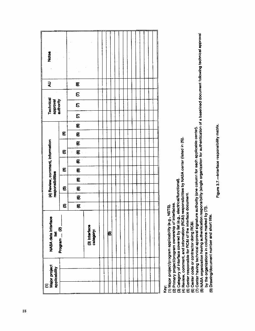
3.3 Initial Issuance of ICD
The first issue of an ICD should be a comment issue. The
comment issue is distributed to participating centers and con-
tractors for review and comment as designated in the interface
responsibility matrix (fig. 3.7).
The interface custodian generates the responsibility matrix
for ICD's. The matrix specifies the center and contractorresponsibilities for baselining, review and comment, and tech-
nical approval. The matrix lists all ICD's applicable to a
particular program. Distribution of the ICD's can then be
controlled through this matrix as well.
The review and comment process is iterative and leads to
agreement on system interface definitions and eventual approvaland baselining of the ICD. See figure 3.8 for a flow diagram of
the issuance, review and comment, and baselining proceduresfor ICD's. Concurrent distribution of the comment issue to all
participants minimizes the time needed for review and subse-
quen. resolution of differences of opinion.
3.4 Document Review and Comment
As designated in the ICD responsibility matrix, all centers
and contractors should submit technical comments through the
appropriate authority to all other activities with review and
comment responsibilities for the particular ICD and to the ICDcustodian.
Technical comments by all activities should be transmitted
to the custodian as soon as possible but not later than 30
working days 4 from receipt of the comment issue. If the
comment issue is technically unacceptable to the Government
authority or the interfacing contractor, the rationale for
unacceptability should be explained, including technical and
cost effects if the interface definition is pursued as presented.
3.4.1 Resolving Comments
The ICD custodian collects review comments and works in
conjunction with project management for comment resolution
until approval is attained, the comment is withdrawn, or the
ICD is cancelled. Information on comments and their disposi-tion and associated resolution should be documented and
transmitted to all participants after all comments have been
received and dispositioned. Allow two weeks 4 for participants
to respond to the proposed resolution. Nonresponses can be
considered concurrence with the resolutions if proper
prenotification is given to all participants and is made part of the
review and comment policy.
When comments on the initial comment issue require major
changes and resolution is not achieved through informal com-
munications, an additional comment issue may be required
and/or interface control working group (ICWG) meetings mayneed to be arranged.
3A.2 Interface Control Working Group
The ICWG is the forum for discussing interface issues.ICWG meetings serve two primary purposes: to ensure effec-
tive, detailed definition of interfaces by all cognizant parties,
and to expedite baselining of initial ICD's and subsequent
drawing changes by encouraging resolution of interface issues
in prebaselining meetings. A major goal of interface control
should be that baselining immediately follow a prebaselining
ICWG meeting.
All ICWG meetings must be convened and chaired by the
cognizant project organization. The project can choose a con-tractor to act as the chair of an ICWG when Government
commitments are not required. In all cases the ICWG members
must be empowered to commit the Government or contractor to
specific interface actions and/or agreements. In cases where a
contractor is ICWG chair, the contractor must report to the
Government any interface problems or issues that surface
during an ICWG meeting.
4Tbe times assigned for commentingactivities to respond are arbitrary andshould be assigned on the basis of the schedule needs of the individualprograms.
17
18

Issuance
I Contractors reviewand comment
IResolution
cycle
ICD custodian
develops commentissue of ICD
I
IComments
t lCD custodian /coordinates and tresolves comments* ]
Technical approvalby NASA centersand contractors
Issuance
Centers reviewand comment
Resolution
cycle
* Interface control
working group meetingsare scheduled as needed.
o, t , ut,ooo,1Monthly status reports ICD to all
participants
Figure 3.8.inFlow of interface control document production.
The ICWG chair prepares the ICWG meeting minutes or
designates one of the meeting participants for this task. The
minutes should include discussions of problems, agreementsreached, decisions made, and action items. The ICWG chair
also ensures that any updated interface control documentation
reflecting the ICWG discussions is distributed within the
timeframe agreed to by the affected participants.
3.4.3 Approval/Signoff Cycle
The management plan for the project assigns responsibility
for each piece of equipment to a specific project authority and
its contractor. The signoff loop for each ICD reflects this plan
and can be related to the project and the origin of each design
requirement. For each ICD, then, the signoff loop follows the
sequence of technical approval by the contractors first and then
by the appropriate project authority.
3.4.4 Technical Approval
The appropriate project authority and the primary and asso-
ciate organizations with an interest in a particular ICD are listed
in the responsibility matrix. They each sign the ICD to signify
technical agreement and a readiness to contractually invoke its
requirements.
3.4.5 Baselining
Interface control documents are baselined when the owners
of both sides of the interface at the next level up in the program
structure come to technical agreement and sign the document.
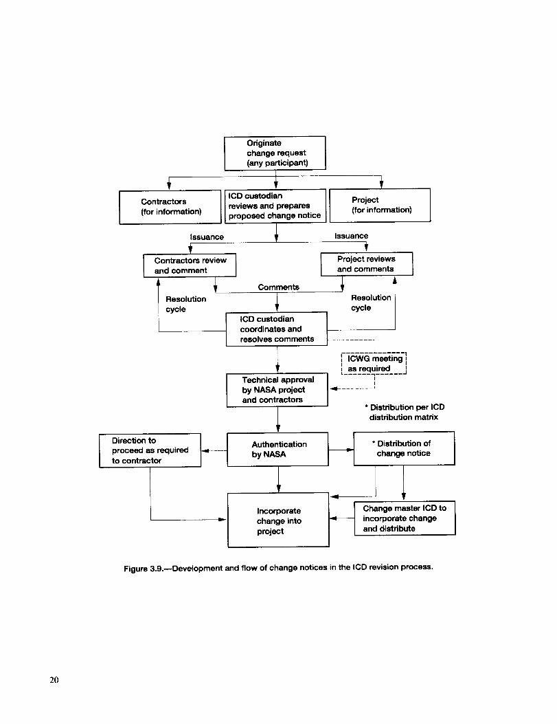
3.5 Change Notices
The procedure for initiation, review, technical approval,
baselining, and distribution of changes to project ICD's
(fig. 3.9) should conform to the following guidelines.
3.5.1 Initiating Changes
Any project activity should request a change to an ICD when
1. Data are available to fill a void.
2. Information contained in a data-required note needs to bemodified.
3. Additional data are needed (i.e., a new data requirementhas been established).
4. A technical error is discovered on the ICD.
19
Contractors [(for information)
Issuance
Contractors reviewand comment
Resolution
cycle
t
Originate
change request
(any participant)
ICD custodian I lreviews and prepares
proposed change notice
IComments
ICD custodian
coordinates and
resolves comments
Technical approval
by NASA projectand contractors
Project
(for information)
Issuance
Project reviewsand comments
Resolution
cycle
.......... i
i ,owGmsetingias required
t ...... ._ ....... J
_ ....... J
* Distribution per ICDdistribution matrix
Direction to
proceed as requiredto contractor
Authentication
by NASA
LIncorporate
change into
project
* Distribution of
change notice
Change master ICD to
incorporate change
and distribute
Figure 3.9.--Development and flow of change notices in the ICD revision process.
2O

5. An equipment design change and a system or equipment
rearrangement are proposed to improve performance,
reduce cost, or expedite scheduled deliveries that would require
changes to an interface or creation of new interfaces.
3.5.2 Requesting Changes
All requests for changes should be submitted to the organi-zation responsible for maintaining the ICD, with copies to all
activities that will review the resultant change notices and to the
appropriate project authority. If baselining is needed in less
than 30 days, a critical change should be requested. All requests
for changes should be submitted in a standard format that
includes the following items:
1. Originator's identification number--It is used as a refer-
ence in communications regarding the request and should
appear on resulting change notices
2. Originating activity--originating project and code or
originating contractor
3. Point of contact--name, area code, telephone number,
facsimile number, and e-mail address of the person at the
originating activity to be contacted regarding the request4. Document affected--number, revision letter, and short
title of each ICD that would be affected by the change
5. Number of data voids (if applicable)--number of data
requirements for which data are being provided
6. Urgency--indication of whether this change is critical or
routine (project decides whether to use critical route)
7. Detailed description of change--a graphic or textual
description of the change in sufficient detail to permit a clear
portrayal and evaluation of the request. Separate descriptions
should be provided when more than one ICD is affected.
8. Justification---concise, comprehensive description of the
need and benefit from the change
9. Impact---concise, comprehensive description of the ef-fect in terms of required redesign, testing, approximate cost,
and schedule effects if the requested change is not approved;
also the latest date on which approval can occur and not affectcost or schedule
10. Authorizing signature of the organization requiring the
change
Upon receipt of a change request to an ICD, the ICD
custodian coordinates the issuance of aproposed change notice.First, the ICD custodian evaluates the technical effect of the
proposed change on the operation of the system and mating
subsystem. If the effect of the change is justified, the ICD
custodian generates and issues a change notice. If the justifica-
tion does not reflect the significance of the change, the ICD
custodian rejects the request, giving the reason or asking forfurther justification from the originating organization. The ICD
custodian evaluates an acceptable change request to determine
whether it provides data adequate to generate a change notice.
The proposed change notice describes the specific changes
(technical or otherwise) to the ICD in detail by "from-to"
delineations and the reasons for the changes, as well as who
requested the changes and how the change request was trans-mitted (i.e., by letter, facsimile, ICWG action item, etc.).
3.5.3 Proposed Change Notice Review and
Comment Cycle
The review and comment cycle for proposed changes to
ICD's should follow the same system as that used for the initialissuance of the ICD (see sections 3.3 and 3.4).
3.5.4 Processing Approved Changes
The baselined change notice should be distributed to all
cognizant contractors and project parties expeditiously to prom-
ulgate the revised interface definition. The master ICD is
revised in accordance with the change notice, and copies of the
revised sheets of the ICD are distributed (see sections 3.3 and
3.4). Approval of the change by the project constitutes author-
ity for the cognizant organization to implement the related
changes on the detailed design.
3.5.5 Distributing Approved Changes
The custodian distributes the baselined change notice to all
cognizant centers and contractors to expeditiously promulgatethe revised interface definition. The master ICD is then revised
in accordance with the change notice, and copies of the revised
ICD sheets are distributed as was the change notice.
The responsibility matrix (fig. 3.7) can be used to identify thedistribution of change notices as it was used for the distributionof the ICD's.
3.5.6 Configuration Control Board
During development the project's configuration control
board is responsible for reviewing and issuing changes to the
configuration baseline. The board reviews all class I engineer-
ing change proposals to determine if a change is needed and to
evaluate the total effect of the change. The configuration
control board typically consists of a representative from the
chairman, the project management office, customers, engineer-
ing, safety assurance, configuration management (secretary),fabrication, and others as required.
Changes to configuration items can only be effected by theduly constituted configuration control board. The board first
defines a baseline comprising the specifications that govern
development of the configuration item design. Proposed changesto this design are classified as either class I or class II changes.
Class I changes affect form, fit, or function. However, other
factors, such as cost or schedule, can cause a class I change.
Class I changes must be approved by the project before being
implemented by the contractor.
21

All other changes are class II changes. Examples of class II
changes are editorial changes in documentation or hardware
changes (such as material substitution) that do not qualify as
class I changes. Project concurrence, generally, is required for
the contractor to implement class II changes. Government plant
representatives (Defense Contracts Administration Services(DCAS), Navy Programs Resident Office (NAVPRO), and Air
Force Programs Resident Office (AFPRO) usually accomplishthese tasks.
3.5.7 Closing the Loop
A wide range of methods are available for verifying by test
that the design meets the technical requirements. During the
definition phase analysis may be the only way of assessing what
is largely a paper design. Typical methods are testing by
similarity, analysis, modeling, and use of flight-proven compo-nents; forecasting; and comparison, mathematical modeling,
simulation modeling, and using flight-proven experience anddecisions. The actual methods to be used are determined by the
project office. Each method has associated costs, requires
development time, and provides a specific level of performanceverification. The Government and industry managers must
carefully trade off program needs for performance verificationwith the related costs.
If any demonstrated or forecast parameter falls outside the
planned tolerance band, corrective action plans are prepared bythe contractor and reviewed by the Government project office.
Each deviation is analyzed to determine its cause and to assess
the effect on higher level parameters, interface requirements,
and system cost effectiveness. Alternative recovery plans are
developed showing fully explored cost, schedule, and technical
performance implications. Where performance exceeds re-
quirements, opportunities for reallocation of requirements andresources are assessed.
Although functional and performance requirements are con-tained in the appropriate configuration item specification, the
definition, control, and verification of interface compatibility
must be handled separately. Otherwise, the volume of detail
will overwhelm both the designers and managers responsible
for meeting the functional and performance requirements of the
system. Early establishment of the interface definition andcontrol process will provide extensive savings in schedule,
manpower, money, and paper. This process will convey pre-cise, timely information to the interface designers as to what the
designer of the opposing side is committed to provide or needs
and will subsequently identify the requirements for verifying
compliance.Whether the interface is defined in a drawing format or in a
narrative format is at the discretion of the program. What is of
primary importance is that only the information necessary todefine and control the interface should be on these contractural
documents to focus the technical users and minimize the need
for updating information.
Appendix G provides seven ICD guidelines that have been
used by many successful flight projects and programs to pro-vide such a focus on the interface definition and control
process.
3.6 Training 2
la. When should the ICD process be started?
A. Concept definition B. Requirements definition
C. Systems integration
lb. What are the benefits of early development of the ICD
process?A. Assigns basic areas of responsibilityB. Provides firm foundation for design, minimizes
paper, shortens schedule, and concentrates efforts
lc. What tool can be used to list equipment and identify their
interrelations in a system?
A. Prechart B. N-squared diagram
2a. What should be done in the ICD process during require-ments definition?
A. Define mission objectives
B. Define technology and interfaces and present for
baselining
2b. What is baselining?
A. The designated authority signing an ICD
B. The only official definition
2c. How are voids in an ICD accounted for and tracked?
A. Procedure or administration report
B. Monthly program status report on interface design
data required
3a. What should be done in the ICD process during develop-ment?
A. Manage voids, invoke brackets, resolve voids, and
verify compliance
B. Control interface developments
3b. How should proposed design changes be handled?
A. Discussed at critical design review
B. Discussed and approved by all participants
3C. What should be given special attention?
A. Design parameters that affect controlled ICD
B. Manufacturing documentation
2Answers are given at the end of this manual.
22

4a. When is the drawing format used for an ICD?
A. To describe the type and nature of the component
B. To describe physical dimensions and shapes
4b. When should a specification be used?
A. To describe performance with tables and textB. To describe a software function
4C. What is the key to providing a useful ICD?A. Give as much detail as possible
B. Limit the detail to what is necessary to demonstrate
compatibility
5a. What is the purpose of the initial issue of an ICD?
A. Issuance, review, comment, and baselining
B. Review and resolution of differences of opinion
5b. Who is responsible for controlling the flow of an ICD?A. Contractor
B. Custodian
6a. Who should review ICD's?
A. Organizations designated in the responsibilitymatrix
B. ICD custodian
6b. How are comments resolved?
A. By the project office
B. By project management and custodian working for
resolution and approval or the comment being with-drawn
6C. Where are interface issues discussed?
A. Project office
B. Interface control working group
6d. Who approves and baselines an ICD?
A. Projects at the next level up in program structure
B. The project office
7a. When should a project activity request achange to an ICD?
A. At the custodian's request
B. When data are available, requirements need change,an error is discovered, or the design changes
7b. What items should be included in a change notice request?
A. Identification number, activity, contact, document
affected, number of data voids, urgency, descrip-
tion, justification, impact, and authorizing signature
B. Those established by the ICWG
7C. Who evaluates and issues a proposed change notice?A. ICD custodian
B. Project office
7d. What does a proposed change notice describe?
A. Specific changes (from-to), reasons, and the
requestor
B. Project notices
7e. How is a change notice approved and distributed?
A. By the project authority to all cognizant parties
B. By all cognizant parties to the contractors
National Aeronautics and Space AdministrationLewis Research Center
Cleveland, Ohio, 44135, July 1995.
23

Appendix A
Electrical/Functional Interface Example
This appendix illustrates elements of a telemetry drawing
interface control document showing control of waveform
parameters and data rates. This interface example depicts datatransfer between a guidance system electronics assembly and a
launch vehicle telemetry system. The basic drawing (fig. A. 1)covers the isolation elements of the guidance system, the jack
and pins assigned, and shielding and grounding on the guidanceside of the interface. Bus functions are named (e.g., guidance
telemetry data 1(parametric)), and the shielding requirements
through to the first isolating elements of the telemetry system
are provided (see notes on fig. A. 1).Table A. 1 contains the details to be controlled for each bus
function. Signal source (electronics assembly) and destination
(telemetry system) are identified. The waveform (fig. A.2) andits critical characteristics (table A.2) are provided, as well as
data rates and sources and load impedances. Telemetry load
impedance is further described by an equivalent circuit (see
note 3 on fig. A. 1).
The final value of pulse minimum amplitude is missing in
this example. This is noted by the design-data-required (DDR)
callout in table A.2 and the accompanying DDR block (fig.
A.3). The DDR block notes that the responsible parties have
agreed on an amplitude band with which they can work until the
guidance design becomes firm. However, there is also a datecalled out that indicates when (45 days after preliminary design
review) the telemetry contractor must have the data to be able
to complete design and development and deliver the telemetry
in time to support launch vehicle flight.
The parameters called out in this example are only thoseneeded to control the design of either side of the interface
through the first isolating element. Also note that only the
shielding and wire gage of the launch vehicle cabling betweenthe two systems are provided. Only pin numbers for the
guidance side of the interface are called out and controlled.Connector types and other pertinent cable specifications are as
per a referenced standard that applies to all launch vehicle
cabling. In this case the same pulse characteristics apply to eachof the functions covered; however, table A.2 is structured to
permit variation for each function if the design should dictatedifferent values for the characteristics of each function.
24

t-O
0r
b.
I
_"="== =i.-i.'i.o !_=.=_=.i" -'i °= ..== ===
_ " "_ = ! = I I " I' l i " I
25

E
_z_
!• O
JE O._ I=
-113
2"_
"_ • .t- _ r-•-- I:: 0
_"0= "5 .--
U C
"- "5 ocO .N
°'i
m = _ ®6o=°aoo E+,I-- _)_- 01--
.9 ®
_,_,_-_0 °_®_I_E
__o_m=
e- <-, _ 10"113
® "-_ _
_..__ _'0 _._
--'_ _'5 m
t--
o
® - =N'_
_< _ _.-_--._ _ ,.,.-o
0 _ 0
°' !_g>
°" i!__ .. _-__ _, _.._ _ _._._g
<
.Q ¢-
0
¢-0
_JE
LI.
_ o,,, oo o,,,_ _ _ -
,, _ _ _ _._
i
_2_ 0
_.__"0 e-
26

Pulse duration
' !
amplitude f_ _ '_ A .-- Minimum amplitudeNoise I _ ...._ . •
i ' J/ _ | No-transmission levelReference
level =,oo,,m°I1\, '
l .....--'_"_a i;ime_/,e _,_/_Undershoot___
.., Interpulse period ' Leading 'Trailing Interpulse periodedge edge
Notes:
1. The interpulse period shall be the period from 150 ns after the trailing edge of
a pulse until 100 ns prior to the leading edge of the subsequent pulse.
2. The reference level shall be the average voltage for the last 200 ns of theinterpulse period.
3. The no-transmission level shall be 0 V differential at the guidance/launch vehicle
interface using the test load specified in table A.2.
4. Shielding depicted represents the telemetry shielding requirements only. For
cable routing see void #01. Telemetry shielding shall be carded through all
connectors between the electronic assembly and the telemetry subsystem.
5. A radiofrequency cap shall be provided on electronic assemblies in all launchvehicles in lieu of this connector.
Figure A.2.--Guidance data pulse characteristics.
27

TableA.2._EQUIREDPULSECHARACTERISTICSANDTESTPARAMETERS
Pulsecharacteristics(seefig.A.2)
PulsedurationMinimumamplitudeMaximumamplitudeRisetimeFalltimeUndershootReferenceleveloffsetNoiseReceiversusceptibilityTestparameters:
TestloadReceiver
susceptibility
Guidancetelemetry
DataI Data2 Bit Frame DataI word Data2wordsynchronizationsynchronizationsynchronizationsynchronization
255+50ns9 _+2 V (see V027)15V
75 ns maximum
125 ns maximum
2.5 V maximum
0 to -4.5 V relative to no-transmission level
1.4 V maximum peak to peak
2.0 V minimum
75 __+5% resistive
2.0 V minimum
DDR No. 3288399-V027
Data required: Guidance subsystem waveform parameter data (minimum amplitudevalue to replace coordinated temporary amplitude band currently on
ICD-3288399)
Data supplier: SP-2012/guidance telemetry steering committee
Data user(s): SP-2732/launch vehicle telemetry contractor/interface coordinator
Date due: 45 days following guidance preliminary design review
Figure A.3.DTypical design data required for table A.2.
28

Appendix B
Mechanica Physical Interface Examples
B.1 Mechanical Interface for
Distributed Electrical Box
Figure B. 1 is an example of an interface development docu-
ment (IDD) that, from initial inspection, appears to be fairly
complete. This figure contains a great amount of detail and just
about everything appears to be dimensioned. However, closer
examination will reveal serious shortcomings.First, the basic function of the interface must be defined. The
box depicted must be capable of being removed and replaced onorbit, in many cases outside the crew habitat. In some cases it
is to be removed and replaced robotically. The box slides along
the L-shaped bracket held to the support structure by threemounting bolts labeled "bolt 1," "bolt 2," and "bolt 3." As the
box slides along the L-shaped bracket from left to right in the
figure, some piloting feature on the box connectors engages the
connectors mounted to the support structure by the spring-
mounted assembly, and the connector engages fully when the
lead screw is completely engaged.
1. The initial interface area to be examined is that of the
L-shaped bracket to the support structure (i.e., the interface of
the three mounting bolts). The interface is being examined from
the perspective of the designer of the support structure. Does
figure B. 1 contain enough information for a mating interface tobe designed? (The area of interest has been enlarged and is
presented as figure B.2.)
a. The dimensions circled in figure B.2 and lettered a, b,
c, and d locate the position of the mounting bolts
relative to the box data. The following pertinent
differences are noted concerning this dimensioning:i. Dimension a locates the holes relative to a "refer-
ence datum for coldplate support structure," but
the datum is not defined on the drawing. Is it a line
or a plane? What are the features that identify/locate
the datum? What is the relationship of this datum toother data identified on the IDD (data A, B, and D)?
This information is required so that the designer
of the support structure can relate his or her
interface features easily to those of the box IDD.
ii. The IDD states that the tolerances on three-placedecimals is +0.010. Dimensions a, b, c, and d
are three-place decimal dimensions and would,
therefore, fall under this requirement. Elsewhere onthe IDD a true position tolerance for bolt locations
is indicated. A feature cannot be controlled by both
bilateral and true positioning tolerancing. It must be
one or the other. Considering the function of the
mounting bolts--to locate the box relative to theelectrical connectors, it has to be assumed
that dimensions a, b, c, and d are basic dimensions.
Interface control drawings cannot require the
designer of the mating interface to assume any-thing. IDD's must stand by themselves.
b. Figure B.3 depicts initial details of mounting bolts
for the L-shaped bracket. On first inspection there
appears to be a great amount of detail. However, furtherexamination shows that much of the detail is not related
to interface definition. The interface is the bolt. Where
is it relative to other features of the box? What is the
relationship of bolts 1 and 2 to bolt 3 (datum C)?
What is the thread of the bolt? How long is the bolt?
The following data on the IDD are not required:i. Counterbore for bolt head
ii. Diameter of bolt hole in bracket for bolts l, 2,and 3
iii. Distance of bolt hole to first thread
iv. The fact that there is a screw retaining ringAdding data not required for the interface, even if they
are only pictorial, is expensive. It takes time for the
organization to develop and present it, and it takes
time for the designer of the mating interface to deter-
mine that the information is not necessary and discardit. If the extraneous information stays on the IDD, it
must be maintained (i.e., changed if the design details
change). Only the features of a design that affect the
features of the design of the mating interfaces need
be placed on the IDD.
c. Once the unnecessary data are removed, what remains
is shown in figure B.4. The data that remain are not
complete and are unclear. The true position notations
are indicated as being those for the "mounting inter-
face for bolt," suggesting that the true position applies
to the hole in the support structure. However, since the
IDD is basically covering the features of the box, it is
assumed that these locations apply to the bolts on the
box. It should not be necessary to have to make
assumptions about data on an IDD or ICD. The
document should stand by itself.
The only other data left in figure B.4 are the callouts for
the locking inserts. These caliouts refer to the method
used by the designer of the support structure for retainingthe bolts. This IDD should not have this callout, since the
29

3O

d c b a
Figure B.2.--Detail of L-shaped bracket interface.
Co_kx10-32 1_ I,,4emdOolt
aoun_ =_=_=c= aoue_ la=t=o=lot 8ons _ _:I 2 Im 8ore3
Figure B.3.---Initial details of mounting bolts•
31

wI_ 6oll 3
Figure B.4.---Necessary details of mounting bolts,
71.000 Max0.875 Min 3 PL_3
Figure B.5.--Minimal interface definition.
method used for retaining the bolts is not the responsibil-
ity of the box designer. Generally IDD's and ICD's
should not specify design solutions, especially when
the design solutions are not the responsibility of the
one specifying them.
What is missing is how far the bolts protrude from the
box. These data are required so that the designer of the
support structure knows how deep to make the matinghole and how much of a mating thread must be supplied
to grip the bolts on the box.
Considering all of the above, figure B.5 represents
what is really required (along with the locations and
thread types already defined in fig. B. 1) to define the boxside of the interface and for the designers of the support
structure to design a compatible interface between the
retaining bolts and the support structure.
2. The next area to be examined is that of the connector
interface. Since both parts of the connector are being provided
by the box designer, the interface is the plate on which theconnectors are attached to the support structure. Again, the
question is, Does figure B. 1 contain enough information for a
mating interface to be designed? The answer to that question is,
Definitely not! The interface of the plate (holding the connec-
tors) that mates with the support structure is identified as datum
D. Again, there is no definition of this datum. Is it a plane
passing through the three highest points of the plate or someother features of the connector plate?
If a compatible mating interface is to be designed, the
relationship between the surface to which the connector plate isattached and the surface to which the L-shaped bracket is
attached must be known. None of these data are supplied in
figure B.1. The following are data needed to establish this
relationship:
32

a. TherequiredperpendicularityofDtoAb. TherequiredparallelismofDtoBc. Therequiredangularrelationshipoftheverticalcenterline
showninviewB-B with the vertical centerline shown in
view A-A
d. The pattern required for the four fasteners holding the
connector plate to the support structure. View B-B does
contain a dimension of 2.594 for a horizontal spacing ofthe lower two features but does not indicate that this
dimension is applicable to the upper two fasteners. Inaddition, there is no dimension for the distance betweenthe fasteners in the Z direction.
e. The required relationship of the hole pattern for the
connector plate relative to the box, namely,i. The location of the hole pattern above A in the Z
direction
ii. The location of the hole pattern relative to C in theX direction
iii. The distance of datum D from C in the Y direction
when the box is fully installed
Since none of these data are identified as items to be determined
(TBD' s), it must be assumed either that the data are not required
because the connectors can be mated properly with a great dealof misalignment or that the box designer did not recognize that
this type of data is required. Designers never wish to freeze a
design. The placement of design constraints in an ICD is
basically freezing an area of a design or at least impeding the
ability to change a design without that design being scrutinized
at another level. Therefore, the tendency of designers is to
disclose the minimum that they feel is necessary in the
interface for the control process. This is the primary reason
for the ICD custodian not to be organizationally a part ofthe design process. Yet the ICD custodian must have access to
the design function of an agency or contractor organization toensure the ready flow of the data required for proper interface
definition. (Can interface compatibility be demonstrated fromthe ICD's alone?)
The ICD custodian must always test the data in interface
documentation from the viewpoint of anotber design agent who
must develop a compatible mating interface.
The preceding discussion simplifies specification of the
L-shaped bracket and the mounting bolts. This redefinition ofthe interface tied up loose ends and provided needed dimen-
sions and callouts absent from the original document. These
portions of the document can now be controlled more easily and
related to a 100% mate design.
B.2 Space Reservation and Attachment
Features for Space Probe Onboard
Titan IV Launch Vehicle
Figure B.6 is an example of an ICD that defines the space
envelope available onboard the Titan IV launch vehicle for apayload and the attachment feature details for the launch
vehicle side of the interface. The intended payload is the
Cassini Mission spacecraft. The Titan payload fairing, as
would be expected, is defined. The other side of this envelope
(i.e., the spacecraft) must also be defined to show compatibility.
When the spacecraft dimensions are established, compatibilityshould be shown by a comparison of the two envelopes. The
Titan documentation defines the available space reserved for
equipment (i.e., a stay-out zone for the Titan launch vehicle
items). Ideally, this ICD should define a minimum space
available for the spacecraft. Therefore, if the spacecraft dimen-
sions are constrained to a maximum size equal to the launchvehicle's minimum, less a value for environmental effects, etc.,
then the two envelopes are compatible.
Since interface data have been provided for the attachment
details for the launch vehicle side of the interface, the design ofthe Cassini adapter for mounting to the Centaur launch vehicle
at station -150.199 can be explained by using the Titan designdata.
The following key interface features have been establishedfor this connection:
1. Sheet 1 (fig. B.6(a)), note 5: Location of holes is estab-
lished by a common master gauge tool with reference dimen-sions provided.
2. Sheet 3 (fig. B.6(c)), section F-F: Bearing areas are to beflat within 0.006 (units), and per view G the maximum bearingarea has been defined.
3. Sheet 3 (fig. B.6(c)), view H: Shape and dimensions of the
shear alignment pins have been established.
4. Sheet 1 (fig. B.6(a)), note 4: How loads are to be transmit-ted is indicated.
The following data elements missing from figure B.6 are
mostly related to the lack of spacecraft design data:1. No apparent tracking of TBD's. A tracking system
should be in place at the beginning of ICD development.
Each TBD should have a unique sequential identifier with
due dates and suppliers established.
2. No revision block for tracking the incorporation ofchanges.
Some type of revision record should be placed on each sheet.
33

° I ° ___ - I
° I - -f - I
J
0
0
D .0
0Z
"IZ
.=_
0
>r-
.__
e"Q.
.__e-
"oe.
r"
IZI
I
I
i
Q
34

÷
÷
• oo _r°
"i<-I
o.(
I,,,.
o,it
:l,.c
_c:
_m
A
I"
4-
>I--@
c-
._-o
._
@
11]
.__U.
35

-t-
m
:)
° i u ? . I "
i
P,i,i
f/i
,gli
0C;0
?
"-1.__
36

Uponexchangeofdesigndatarelating to the Cassini probe it
would be expected that the probe's maximum envelope would
be established and related to the data system of the Titan/Centaur launch vehicle.
This example is basically a one-sided interface. The Titan/Centaur side of the interface is well defined, which is to be
expected considering the maturity of the design. The tendency
should be resisted, in cases like this, to ignore or place less
emphasis on the definition and documentation of the mating
interface, given the completeness of the launch vehicle side of
the interface. The mating interface, namely, the spacecraft side,
should be completely defined. Otherwise, the spacecraft de-
signer will be signing up to design a compatible interface byagreeing with what the interface on the launch vehicle side
looks like. Although this approach allows freedom to go offand
"do independent things," it lacks the degree of positive control
needed for interface compatibility. The chances for an incom-
patibility are much less if the spacecraft side of the interface is
defined. Space vehicle data, stations, and fasteners must be
identified and controlled. The designer of the space vehicle isthen able to commit to the design and production of an interface
that is defined. The launch vehicle designers can then verifythat the spacecraft interface will mate with the launch vehicle
available for the spacecraft. Therefore, if the spacecraft dimen-
sions are constrained to a maximum size equal to the launch
vehicle' s minimum, less a value for environmental effects, etc.,
then the two envelopes are compatible.
Since interface data have been provided for the attachment
details for the launch vehicle side of the interface, the designof the Cassini adapter for mounting to the Centaur launch
vehicle at station-150.199 can be explained by using the Titan
design data.
37

Appendix C
Software Interface Example:
Definitions and Timing Requirements for Safety
Inhibit Arm Signals
Signal definition
Satellite vehicle (SV)
pyro unshort
(primary)
Centaur sequence
control unit
switch number
Radiofrequency
monopropellant driver
backup enable
45
Initiating event + time
Main engine cutoff
(MECO) 2 + 3£-0.5 sec
Persistence
3:L-0.5 sec
3:L-0.5 sec
Function
Unshorts SV pyro capacitor banks
Arms safety inhibit relay for SV
main enginesSV latch valve 33 MECO2 + 10-2-0.5 sec
arm (primary)
SV pyro unshort 89 MECO2 + 15_+0.5 sec 3_+0.5 sec Provides redundant unshort of SV
(secondary) pyro capacitor banks
SV latch valve 88 MECO2 + 17_+0.5 sec 3L_0.5 sec Provides redundant arm of inhibit
arm (secondary) relay for SV main engines
34 Titan IV/Centaur 3_+0.5 sec
separation + 24-+0.5 sec
Services backup (redundant to SV
ground support equipment com-
mand) enable of safety inhibit SV
functions (radiofrequency sources
and reaction control system thruster
drivers)
38

Appendix D
Supplied Services Interface Example
This appendix provides a simplistic text-based example of a
supplied services (air-conditioning and cooling water) inter-
face control document with a typical design-data-required
(DDR) block. This example contains elements condensed from
a number of service documents originally used for a submarine
weapons program; however, the principles contained herein are
universally applicable to any complex system of interfaces.
Page I of the ICD lists the DDR's (table D. 1) showing DDR
numbers, location on the drawing, brief description, and due
date. The DDR block (fig. D. 1) on the drawing expands on this
information and identifies supplier, user, and time urgency of
the data needed. The DDR numbering convention used here is
"V09 = Void #09." Preceding the void number with the ICD
number provides a program-unique DDR number that is easily
related to its associated ICD and easily maintained in a database.
TABLE D.I .--DESIGN-DATA-REQUIRED SUMMARY
AND LOCATOR
Void
number
V01
V09
Location
Sheet 1,
zone C-7
Description Date due
Main heating 30 Days after
and cooling authentication of
(MHC) water data fulfilling
schedule DDR 5760242-V12
DDR No. 1466134-V09
Data required: Heating and cooling (HC) system upper zonewater schedule (supply water temperature versusenvironmental temperature)
Data supplier.
Data user.
Date due:
HC working group
Launch vehicle design agent
30 days after authentication of data fulfilling DDR No.2543150--V12
Figure D.1 .mTypical design-data-required block.
39

The following pages present the kinds of data required to fully
define the air-conditioning requirements for suites of equip-ment located in a launch control center. Table D.2 details
conditioned-air distribution; table D.3 presents typical inter-
face data required to ensure that a cooling water service is
provided to electrical equipment and indicates requirements for
the equipment before and after the incorporation of an engi-
neering change.
701. Launch vehicle control center services:
A. Air-conditioning shall be provided with a dedicated
closed-circuit system capable of supplying a mini-mum total flow of 12 820 scfm with a 50% backup
capability.1. The conditioned air shall be distributed to each
equipment flue as specified in table D.2. The distrib-uted conditioned air at the inlet to the equipment
shall satisfy the following parameters:
a. Temperature: The minimum temperature shall be65 °F and the maximum, 70 °F.
b. Humidity: The maximum humidity shall be 75
grains per pound of dry air.c. Working pressure: The working pressure shall
be enough to overcome equipment pressure drops
and to maintain positive pressure at the equip-ment outlet with respect to compartment ambi-
ent pressure. A 10% minimum leakage rate in the
compartment shall be assumed.d. Flow resistance: The system shall be able to over-
come the pressure drop across the equipment (i.e.,from exit of orifice plate to top of equipment) as
shown in table D.2.
e. Flow profile:(1) The flow distribution for each flue shall be
such that the flow velocity between the flue
centerline and 1.3 in. from the edge of the flue,
and (where equipment permits) 6 in. above the
flue gasket, shall not be less than 80% of the
achieved average flow velocity. The achieved
average flow velocity must equal or exceed veloc-
ity based on the minimum flow rate specified intable D.2.
(2) Velocity profiling is not required for flues
designated 301 through 310, 011 through 015,446BC, 405-2A, 405-2B, 405-6A, and 405-6B.
f. Adjustment capability: The system shall provide
flow adjustment from 0 to 300 scfm at each of the
equipment flues requiring velocity profiling.
g. Air quality: Air at the inlet to the equipment shall
be equivalent to or better than air filtered through
a 0.3-I.tm filter with an efficiency of 95%.
2. The closed-loop system shall have the capacity of
removing 52.8 kW (minimum) of heat dissipated by
equipment using closed-circuit conditioned air. Thisheat load includes 1.3 kW reserved for launcher
equipment in the launch vehicle control center (see
note 702 below).
702. The system shall provide the capability of removing1.65 kW minimum of heat dissipated by equipment by using
compartment ambient air as a cooling medium while maintain-
ing the compartment within specified limits.
A. The ship shall take no action that eliminates the optionfor launcher equipment to use compartment ambient air
or closed-circuit conditioned air for dissipating launcher-
generated heat of 1.3 kW.B. Heat dissipated to ambient air by equipment using
closed-circuit conditioned air is not included.
703. The system shall provide distribution trunks to equip-
ment flues with total flow capacity as designated below for theconditions of table D.2:
Trunk Minimum
flow,
scfm
A 2700
B 1620
C 2300
D 3400
E 1300
F 1500
704. Flow at reference designations marked with an asteriskin table D.2 are to be considered flow reserve capabilities.
These designated flues do not require verification of flow per
table D.2 nor profiling per note 701.A. 1.e(1 ) until these fluesare activated. The Government-furnished pipe assemblies and
caps will be supplied for flues not activated.
705. The minimum flow for flues 446BC and 447BC is
100 scfm before change 30175 and 250 SCFM after change30175.
40

Equipment Trunk
(see note
703)
TABLE D.2._ONDITIONED-AIR DISTRIBUTION
Flue Minimum Flow resistance/
Data cabinets A
Data console A
Control console E
Power buffer and B
conversion
DControl computer
group
Control group E
Power distribution F
Load F
*Flow reserve capability.
301B
301C
305B
305C
306B
306C
308B
308C
309
31013
310C
405-2A
405-2B
405-6A
405-6B
011
012
013-1
013-2
015
440BC
440--441D
444BC
444--445D
flow,
scfm
225
260
80
80
290
50
100
50
0*
135
50
100
100
50
50
440
440
150
150
440
200
300
3OO
250
446BC See note
447BC 705
471 200
450BC 200
450-451D 200
451BC 100
452BC
452--453D
458BC
458-459D
459BC
200
200
200
200
150*
472 150"
002BC
003BC
004BC
004D
271BC
271D
005BC
005D
150
150
150"
150"
275
0*
100"
0*
pressure drop at
minimum flow (see
note 701A. 1.d),
in. H20
0.54
.50
.50
.56
.50
.50
.50
.5O
.50
1.0
2.0
1.0
1.0
0
1.0
0
41

TABLED.3.--WATERFLOW RATE INTERFACE PARAMETERS
[Water inlet temperature: 54 °F max and 48 °F min; temperature alarm set at 56 °F 5:1 deg F (increasing) and 47 °F :1:1 deg F (decreasing); see Remarks.
Working pressure: 85 psig max and 57 psig min. Test pressure, 125 psig max with binnacles to be isolated at vehicle hydrostatic test. Pressure drop: nominal
differential pressure range, 13 to 23 psid ref. Water quality: dual filters required; filters to 10 lam with 98% efficiency by weight, 20/am absolute.]
Function Minimum cooling Water flow rate Remarks
capability
2.25-kW gainElectrostatically supported
gyro navigator (ESGN) and
gravity sensor system (GSS)
binnacle cooling
a6.0-gal/min nominal total flow for twoESGN binnacles and one GSS binnacle.
The supply shall maintain constant flow
of 2.0 gal/min +10% to each binnacle.
bA remote, low-flow alarm shall be pro-
vided for the ESGN binnacles and the
GSS binnacle.
Reserve capability for future 3.25-kW gain 2.6-gal/min minimum
navigation development
ESGN binnacle cooling 1.5-kW gain
Reserve capability for future
navigation development
4.0-kW gain
a4.0-gal/min nominal total flow for two
ESGN binnacles. The supply shall main-
tain a constant flow of 2.0 gai/min +_10%
to each binnacle.
bA remote, low-flow alarm shall be pro-
vided for the ESGN binnacles.
4.5-gal/min minimum
Reliability of water supply shall support a navigation
subsystem availability of 0.97. This service requirement
shall be continuously available during patrol and refit.
The water temperature shall not vary by more than
6 deg F when changing at the rate of 0.25 deg F/sec
maximum. This change shall not occur more than once
per 30-min period.
aThe system shall provide test connections at the inlet and outlet of each binnacle to permit periodic measurement of differential pressure.
bLocal flow indication shall be provided for each binnacle.
42

Appendix E
Compatibility Analysis
E.1 Definition
Compatibility analysis of the interface definitions contained in
an ICD is a major tool of interface control. It serves a twofold
purpose:
1. Demonstrates completeness of interface definition. If any
interface data are missing or presented in a manner that cannot be
integrated by using the ICD alone as a data source, the ICD isconsidered deficient.
2. Provides a record (traceability) that the interface has been
examined and found to have the fight form and fit. This record
can then be used in evaluating the acceptability of subsequentchange proposals.
E.2 Kinds of Data
The following compilation identifies the kinds of data that
must be obtained for a compatibility analysis and outlines the
general steps that should be followed for three categories of
interface: electrical/functional, mechanical/physical, software,and supplied services:
I. Interface category--electrical/functional
A. Data required to perform analyses
1. The following parameters are required, consideringthe specific function or signal involved:
a. Cabling and connectors
b. Power requirements
c. Electromagnetic interference, electromagnetic
compatability, electromagnetic radiation, and
grounding requirements
d. Functional flow and timing requirements
e. Signal definition
f. Digital data definition to the bit level
g. Protocol levels
h. Seven-layer International Standards Organizationopen systems instruction stack definition or its
equivalent
i. Error recovery procedures
j. Startup and shutdown sequences
k. Adequacy of standards used or referenced
2. Unique requirements for an interface or a piece of
equipment different from overall system require-
ments (i.e., the hierarchy of specifications required)3. Adequate definition of all signals crossing the inter-
face. "Adequate" is difficult to define precisely but
depends on the signal type (e.g., analog or digital)and the intended use. In general, the interface must
show the characteristics of the isolating device (ele-ment) on each side of the interface and define the
signal characteristics in engineering terms suitablefor the particular type of signal.
4. Timing and other functional interdependencies5. System handling of error conditions
6. Full definition of any standards used. Most digital
transmission standards have various options thatmust be selected; few, if any, standards define the
data that are passed.
B. Steps to be followed
1. Verify interoperability of connectors.2. Size cables to loads.
3. Determine cable compatibility with signal and envi-ronmental conditions.
4. Define data in one document only.
5. Determine adequency of circuit protection devicesand completeness of signal definition.
II. Interface category--mechanical/physical
A. Type of interface form and fit
1. Data required to perform analysis
a. A datum (reference) that is common to both sides
of the interface (e.g., a mounting hole in one partthat will mate with a hole or fastener in the other
mating parts or a common mating surface of the
two mating parts)b. Dimensions and tolerances for all features of each
part provided in a manner that gives the optimuminterface fit and still provides the required design
functions. Optimum interface means dimension-
ing so that the tolerance accumulation is kept to aminimum.
2. Steps to be followeda. Start with the common datum and add and subtract
dimensions (adding the tolerance accumulations
for each dimension) for each feature of the partinterface.
b. Determine the dimensional location of the
interface-unique features by adding and subtract-
ing the tolerance accumulations from resultingdimensions to achieve the worst-case maximum
and minimum feature definitions.
c. Perform the same analysis for the mating features
of the interfacing part.
d. Compare and question the compatibility of the
worse-case features of the two mating parts (Will
43

the maximum condition of one part fit within the
minimum condition of the mating part?)
B. Type of interface--structural load
1.Data required to perform analysis
a. A description of the loading conditions (static or
dynamic) and the duration of those conditionsb. Characteristics of the equipment involved: weight
or mass; mass distribution; elastic properties; and
sensitivity of elastic properties to temperature,
moisture, atmospheric gas content, pressure, etc.
2. Steps to be followed. This analysis involves placingthe interfacing items in a position that produces themaximum loads while the items are interfacing. A
space experiment is primarily designed for flight
loads, yet it must withstand the loads developed
during the launch and deployment cycles and per-
haps unique loads during launch processing. The
complexity of the compatibility analysis will vary
depending on the types of interfacing items andenvironments.
a. Attachment loads are the simplest, being a state-
ment of the loads applied by the attaching feature
(bolt) and the load capability of the component
being retained (flange).b. Hoisting and handling loads require the calcula-
tion of bending moments or shear for various
loading scenarios. Dynamic and environmental
loads must also be considered. (How quickly is the
load applied? What are the wind loading factors?)
c. A more complex situation will be the loads devel-
oped during a dynamic interaction of interfacingitems where different material characteristics must
be considered along with the reaction characteris-tics of the materials (e.g., a flexible beam of
varying moments of inertia supported by an elas-tomeric medium where the entire system is
subjected to a high-velocity impulse of a fewmicroseconds duration). Such a condition could
produce loads that exceed those for which one ofthe interfacing items is designed. Another inter-
facing item may have to be redesigned so as not tojeopardize the mission of the primary item (i.e.,
increasing the strength of the item being supported
could increase the weight).
III. Interface category--softwareA. Type of interface--software. The ICD is required to
specify the functional interface between the computer
program and any equipment hardware with which itmust operate. Often, the supplier documentation for
standard computer peripherals and terminals is ad-
equate for this purpose. Conversely, it has been found
that performance specifications governing the designof new equipment are not satisfactory for use in a
functional ICD. The purpose of an ICD is to communi-
cate equipment interface requirements to programmersin terms that the programmers readily and accurately
understand and to require equipment designers to con-
sider the effect of their designs on computer programs.
B. Type ofinterface--hardware/software integration. The
ICD provides an exact definition of every interface, by
medium and by function, including input/outputcontrol codes, data format, polarity, range, units, bit
weighting, frequency, minimum and maximum timing
constraints, legal/illegal values, accuracy, resolution,
and significance. Existing documentation may be ref-erenced to further explain the effect of input/output
operations on external equipment. Testing required tovalidate the interface designs is also specified.
IV. Interface category--supplied services
A. Type of interface fluid service
1. Data required to perform analysisa. Type of fluid required by the equipment and
type of fluid the service supplier will provide.
This may be in the form of a Federal or military
specification or standard for both sides or forone side of the interface.
b. Location of the equipment/service interface
(hose connection, pipe fitting, etc.)
c. Equipment requirements at the interface loca-
tion in regard to characteristics (pressure, tem-
perature, flow rate, duty cycle, etc.)
d. Capability of the service supplierattheinterfacelocation
e. Manner in which the equipment can affect the
capability of the service supplier (e.g., having a
large backpressure that the supplier fluid must
push against or a combination of series and
parallel paths that the supplier fluid must pass
through)
2. Steps to be performed. Examine the supplier and
equipment requirements to determine
a. If the supplier capability meets or exceeds the
equipment requirements. This may require con-
verting a Federal/military specification or stan-
dard requirement into what is specified for the
equipment.
b. If the supplier capability meets the require-ments, considering the effects resulting from the
fluid passing through the mating equipment
B. Type of interface--environmental
I. Data required to perform analysisa. Conditions required for equipment to function
properly. Storage, standby, and operatingscenarios need to be established and defined.
b. Supplier's capability to provide the environ-
ment specified in terms of time to reach steady
44

statefromtransientsresultingfromuncontrol-lableexternalenvironments;the limits of the
steady-state conditions (maximum/minimum);
and monitoring features
2. Steps to be performed. Perform analyses (e.g.,thermal) under extreme and nominal environmen-
tal conditions to verify that supplier's equipment
can maintain the environment required for the
equipment. The complexity of the analysis may
vary depending on the types of item involved.
a. Simple inspection, which considers the environ-
ment required by an item versus the capability ofthe ambient in which the item resides
b. Complex analysis, which must consider uncon-
trolled external environmental inputs, the ther-
mal properties of intermediate systems that donot contribute to the end environment but act as
conduits or resistors in the model, and the inter-
action of the item and the system that controlsthe desired environment
45

Appendix F
Bracket System for Interfaces
Brackets are used on hardware/engineering drawings to flag
or identify details controlled by the ICD. Changes cannot bemade to the drawings or designs without the effects on the
interface being assessed and coordinated through the ICD
process.The process uses a rating similar to that used in the problem/
failure reporting bracket system with the same controls and
traceability. Once a bracket has been assigned to an interface
void or problem, specific analyses and actions are required forthe bracketed item to be removed. The bracketed item remains
in open status with assignment to the responsible cognizant
subsystem or design section until (1) the corrective action orcoordinated information has been developed, (2) a proper risk
assessment has been performed, (3) ICD change actions have
been completed, (4) adequate verification of the interface is
planned, and (5) the proper approval signatures have beenobtained.
The following ratings are used to establish a category of"bracket" identifiers for interface deficiencies. Any discrep-
ancy having an A rating greater than I or a B rating greater than2 will be designated a bracketed discrepancy (see figure F. 1).
I. Interface deficiency rating A (S&MA impact)
A. Rating Al: Negligible effect on interface or mission
performance1. No appreciable change in functional capability (form,
fit, and function are adequate for the mission)
2. Minor degradation of engineering or science data
3. Support equipment or test equipment failure but notmission-critical element failure
4. Support-equipment- or test-equipment-inducedfailures
B.
II.
5. Drawing errors not affecting element construction
Rating A2: Significant degradation to interface or
mission performance1. Appreciable change in functional capability
2. Appreciable degradation of engineering or sciencedata
3. Significant operational difficulties or constraints4. Decrease in life of interfacing equipment
5. Significant effect on interface or system safety
C. Rating A3: Major degradation to interface or mission
performance or catastrophic effect on interface or
system safetyInterface deficiency rating B (understanding of risk)
A. Rating B 1: Effect of interface deficiency is identified
by analysis or test, and resolution or correctiveaction is assigned and scheduled or implemented
and verified. There is no possibility of recurrence.
B. Rating B2: Effect of interface deficiency is not fullydetermined. However, the corrective action proposed,
scheduled, or implemented is considered effective in
correcting the deficiency. There is minimal possibilityof recurrence and little or no residual risk.
C. Rating B3: Effect of interface deficiency is wellunderstood. However, the corrective changes pro-
posed do not completely satisfy all doubts or concerns
regarding the correction, and the effectiveness ofcorrective action is questionable. There is some poss-
ibility of recurrence with residual risk.
D. Rating B4: Effect of interface deficiency is not wellunderstood. Corrections have not been proposed or
those proposed have uncertain effectiveness. There is
some possibility of recurrence with residual risk.
46

Interface discrepancy red flag;project or task manager approval required
Rating A
(S&MA impact)
Negligible
impact
Significant
degradation
Major
degradation
Numerical rating
1 1
2 2
3 3
4
Rating B
(understanding of risk)
Known deficiency with corrective action
assigned, scheduled, and implemented
Deficiency poorly defined but acceptable
corrective action proposed, scheduled, and
implemented (low residual risk)
Known deficiency but effectiveness ofcorrective action is unclear and does not
satisfy all doubts and concerns (residual risk)
Impact not defined with confidence;corrective action with uncertain
effectiveness (residual risk)
Figure F.1 .mlnterface deficiency rating system.
47
Appendix G
ICD Guidelines
1. Interface control documents should not require the designer of the
mating interface to assume anything. ICD's should be compatible witheach other and stand alone.
2. Only the definition that affects the design of the mating interfacesneed be used.
o
.
tion.
ICD's should not specify design solutions.
The ICD custodian should be independent of the design organiza-
5. The ICD custodian should verify that the data being controlled by
an ICD are sufficient to allow other organizations to develop the
interface described by the ICD.
6. An interface control system should be in place at the beginning of
system (hardware or software) development.
7. Each void should have a unique sequential identifier establishing
due dates, identifying exact data to be supplied, and identifying the data
supplier.
48

Appendix H
Glossary
baseline---The act by which the program manager or a desig-
nated authority signs an interface control document (ICD) and
by that signature establishes the genuineness of the ICD as an
official document defining the interface design requirements.The term "baseline" conveys the idea that the ICD is the only
official definition and that this officiality comes from the
technical management level. Not only is the initial version of
the ICD baselined, but each change to an ICD is likewise
approved.
comment issue--An issue of an ICD distributed for review and
comment before a meeting of the affected parties and before
baselining
custodian--The contractor or project assigned the responsibil-ity of preparing and processing an ICD through authentication
and subsequently through the change process
data--Points, lines, planes, cylinders, and other geometric
shapes assumed to be exact for the purpose of computation and
from which the location or geometric relationship (form) of
features of a piece of equipment can be established
interface responsibility matrix--A matrix of contractors,
centers, and project organizations that specifies responsibilities
for each ICD listed for a particular task. Responsibilities aredesignated as review and comment, technical approval,
baselining, and information.
electrical/functional interface--An interface that defines the
interdependence of two or more pieces of equipment when the
interdependence arises from the transmission of an electrical
signal from one piece of equipment to another. All electrical
and functional characteristics, parameters, and tolerances of
one equipment design that affect another equipment design arespecified.
interface---That design feature of one piece of equipment that
affects a design feature of another piece of equipment. An
interface can extend beyond the physical boundary between
two items. (For example, the weight and center of gravity of
one item can affect the interfacing item; however, the center of
gravity is rarely located at the physical boundary. An electrical
interface generally extends to the first isolating element rather
than terminating at a series of connector pins.)
interface control--The process of (1) defining interface re-
quirements to ensure compatibility between interrelated pieces
of equipment and (2) providing an authoritative means of
controlling the interface design.
interface control document (ICD)--A drawing or other docu-
mentation that depicts physical and functional interfaces ofrelated or cofunctioning items. (The drawing format is the most
common means of controlling the interface.)
interface control working group--A group convened to
control and expedite interface activity between the Govern-
ment, contractors, and other organizations, including resolu-
tion of interface problems and documentation of interface
agreements
interface definition--The specification of the features, char-
acteristics, and properties of a particular area of an equipmentdesign that affect the design of another piece of equipment
interoperability--The ability of two devices to exchange
information effectively across an interface
mechanical/physical interface---An interface that defines themechanical features, characteristics, dimensions, and toler-
ances of one equipment design that affect the design of another
subsystem. Where a static or dynamic force exists, force
transmission requirements and the features of the equipmentthat influence or control this force transmission are also de-
fined. Mechanical interfaces include those material properties
of the equipment that can affect the functioning of matingequipment or the system (e.g., thermal and galvanic
characteristics).
software interface--The functional interface between the
computer program and any equipment hardware with which itmust operate. Tasking required to validate the interface designs
is also specified.
supplied-services interface---Those support requirements that
equipment needs to function and that are provided by an
external separate source. This category of interface can be
further subdivided into environmental, electrical power, and
communication requirements.
technical approval The act of certifying that the technical
content in an interface document or change issue is acceptable
and that the signing organization is committed to implementing
the portion of the interface design under the signer' s cognizance.
49

FED-STD-209E: Airborne Particulate Cleanliness Classes in Cleanrooms and
References Clean Zones. Federal Standard, Sept. 1992.
1. MIL-STD--499: Engineering Management. May 1974.
2. Blanchard, B.S.; and Fabrycky, W.J.: Systems Engineering and Analysis.
Prentice-Hall Inc., 1981.
3. MlI_,-STD-1521B: Technical Reviews and Audits for Systems, Equip-
merit, and Computer Software, Notice 1, Dec. 1985.
4. Kockler, F.; Withers, T.; Poodiack, J.; and Gierrnan, M.: Systems Engi-
neering Management Guide. Defense Systems Management College,
Fort Belvior, VA, Jan. 1990.
5. ICD-Titan IV/Satellite Vehicle-24027, Cassini Mission. Martin Marietta
Technologies, Inc., Denver, CO, Jan. 1994.
6. MIL-STD-490A: Specification Practices. Military Standard, June 1985.
7. ANSI Standard Y14.5: Dimensioning and Tolerancing.
8. DOD-STD-100: Engineering Drawing Practices.
9. SAMSO-STD 77-4: Format and Requirements for Interface Documents.
Space & Missile Systems Org., Jan. 1979.
10. MIL--STD-704: Aircraft Electrical Power Characteristics.
Bibliography
AFR 65-3, AR 70-37, NAVELEXINST 4130.1, and 4139.1 A: Joint Services
Regulation on Configuration Management. Air Force Regulation, Naval Elec-
tronics Systems Instructions, Marine Corp Order.
AFSCP 800-7: Configuration Management. Air Force Systems Command
Pamphlet.
DOD 4120.3-M: Defense Standardization and Specification Program Policies,
Procedures and Instructions, Aug. 1978.
DOD 4245.7-M: Transition From Development to Production. Military Speci-
fication, Sept. 1985.
DOD 5010.19: Configuration Management. Military Specification, July 1990.
DOD--D-1000B: Drawings, Engineering and Associated Lists. Military Speci-
fication, July 1990.
DOD-STD-480B: Configuration Control_Eagineering Changes, Deviations,
and Waivers, July 1988. (Cancelled July 1992.)
ESMC Req 160-1: Radiation Protection Program. Eastern Space & Missile
Center, Patrick AFB, FL.
Fairley, R.E.: Software Engineering Concepts. McGraw-Hill, New York,
1985.
KHB 1860.1: Kennedy Space Center Ionizing Radiation Protection Program.
Kennedy Space Center, FL, 1972.
MCR-86-2550: Titan IV System Contamination Control Plan. Martin Marietta
Aerospace Corp., Denver, CO, or Bethesda, MD, 1987.
MIL-B-5087B: Bonding, Electrical and Lightning Protection for Aerospace
Systems. Military Standard, Dec. 1984.
MIL-N-7513F: Nomenclature Assignment, Contractor's Method for Obtain-
ing. Military Standard, Notice 2, July 1993.
MIL-ltDBK-259: Life Cycle Cost in Navy Acquisitions. Military Handbook,
Apr. 1983.
MIL--P-27401 C: Propellant Pressurizing Agent, Nitrogen. Military Standard,
Aug. 1988.
MIL-S-83490: Specifications, Types and Forms. Military Standard, Oct.
1968.
MIL-STD-10OE: Engineering Drawing Practices. Military Standard, Sept.
1992.
MIL-STD-482A: Configuration Status Accounting Data Elements and Re-
lated Features. Military Standard, Sept. 1968.
MIL-STD-973: On Configuration Management Practices for Systems, Equip-
ment, Munitions, and Computer Software. Military Standard, 1993.
MIL-STD-1246C: Product Cleanliness Levels and Contamination Congol
Program. Military Standard, Apr. 1994.
MIL-STD- 1388-1 A: Logistic Support Analysis Reviewer. Military Standard,
Mar. 1991.
MIL-STD-1456: Contractor Configuration Management Plans. Sept. 1989.
(Cancelled July 1992.)
MIL-STD-1528A: Manufacturing Management Program. Military Standard,
Sept. 1986.
MIL-STD-1541: Electromagnetic Compatibility Requirements for Space
Systems. Military Standard, Dec. 1987.
PD 699-120: Cassini Final Targeting Specification. Program Directive, NASA
or Executive Office of the President.
SECNAVINST 4130: Navy Configuration Management Manual. Executive
Office of the Secretary of the Navy.
50

Training Answers
Chapter
1
Answers
I(A); 2(D); 3(C); 4a(C), 4b(A), 4c(B)
I(D); 2(C); 3a(B), 3b(C); 4a(C), 4b(C), 4c(C);
5a(A), 5b(A), 5c(A); 6a(C), 6b(A), 6c(A);
7a(B), 7b(B), 7cA(i), 7cB(ii), 7cC(i); 8a(B),
8b(A); 9a(A), 9b(A), 9c(B)
la(A), lb(B), lc(B); 2a(B), 2b(A), 2c(B);
3a(A), 3b(B), 3c(A); 4a(B), 4b(A), 4c(B);
5a(A), 5b(B); 6a(A), 6b(B), 6c(B), 6d(B);
7a(B), 7b(A), 7c(A), 7d(A), 7e(A)
51

Form ApprovedREPORT DOCUMENTATION PAGE OMB No 0704-0188
Public reporting burden for this collection of information is estimated to average 1 hour per response, including the time for reviewing instructions, searching existing data sources,gsthenng and maintaining the data needed, and completing and reviewing the collection of information. Send comments regarding this burden estimate or any other especl of thiscollection of information, including suggestions for reducing this burden, to Washington Headquarters Services, Directorate for Information Operations and Reports, 1215 JeffersonDavis Highway, Suite 1204, Adington, VA 22202-4302, and to the Office of Management and Budget, Paperwod_ Reduction Project (0704-0188), Washington, DC 20503.
1 AGENCY USE ONLY (Leave blank) 2. REPORT DATE 3. REPORT TYPE AND DATES COVERED
January 1997 Reference Publication
4. TITLE AND SUBTITLE S. FUNDING NUMBERS
Training Manual for Elements of Interface Definition and Control
6. AUTHOR(S)
Vincent R. Lalli, Robert E. Kastner, and Henry N. Hartt
7. PERFORMING ORGANIZATION NAME(S) AND ADDRESS(ES)
National Aeronautics and Space Administration
Lewis Research Center
Cleveland, Ohio 44135 -3191
9. SPONSORING/MONITORING AGENCY NAME(S) AND ADDRESS(ES)
National Aeronautics and Space Administration
Washington, DC 20546-01301
WU-323-42-02
8. PERFORMING ORGANIZATION
REPORT NUMBER
E-9790
10. SPONSORING/MONITORING
AGENCY REPORT NUMBER
NASA R_P- 1370
11. SUPPLEMENTARY NOTES
This manual was edited by Vincent R. Lalli, NASA Lewis Research Center; Robert E. Kastner, Vitro Corporation,
Rockville, Maryland; and Henry N. Hartt, Vitro Corporation, Washington, De. Responsible person, Vincent R. Lalli,
(216) 433-2354.
1211. DISTRIBUTION/AVAILABILITY STATEMENT 12b. Dh_T_IBUTION CODE
Unclassified - Unlimited
Subject Category 15
This publication is available from the NASA Center for Aerospace Information, (301) 621-0390,
Multiple copies are for sale by the National Technical Information Service, Springfield, VA 22161,
(703) 487--4822.
13. ABSTRACT (Maximum 200 words)
The primary thrust of this manual is to ensure that the format and information needed to control interfaces between
equipment are clear and understandable. The emphasis is on controlling the engineering design of the interface and not on
the functional performance requirements of the system or the internal workings of the interfacing equipment. Interface
control should take place, with rare exception, at the interfacing elements and no further. There are two essential sections
of the manual. Chapter 2, Principles of Interface Control, discusses how interfaces are defined. It describes different types
of interfaces to be considered and recommends a format for the documentation necessary for adequate interface control.
Chapter 3, The Process: Through the Design Phases, provides tailored guidance for interface definition and control. This
manual can be used to improve planned or existing interface control processes during system design and development. It
can also be used to refresh and update the corporate knowledge base. The information presented herein will reduce the
amount of paper and data required in interface definition and control processes by as much as 50 percent and will shorten
the time required to prepare an interface control document. It also highlights the essential technical parameters that ensure
that flight subsystems will indeed fit together and function as intended after assembly and checkout.
14. SUBJECT TERMS
Systems engineering; Configuration control; Documentation;
Change notices; Interface management
17. SECURITY CLASSIFICATION
OF REPORT
Unclassified
18. SECURITY CLASSIFICATION
OF THIS PAGE
Unclassified
NSN 7540-01-280-5500
19. SECURITY CLASSIFICATION
OF ABSTRACT
Unclassified
15. NUMBER OF PAGES
60
16. PRICE CODE
A04
20. LIMITATION OF AB._ACT
Standard Form 298 (Rev. 2-89)
Pre_.cribod by ANSI Std. Z39-18298-102


_'o
.. - om__ Ox" -'oe_ ","_ _ _-
_ m0
z (,0
C