NASA Icing Remote Sensing Andy Reehorst NASA Glenn Research Center Dave Serke NCAR.
7
NASA Icing Remote Sensing Andy Reehorst NASA Glenn Research Center Dave Serke NCAR
-
Upload
vivien-lane -
Category
Documents
-
view
220 -
download
0
Transcript of NASA Icing Remote Sensing Andy Reehorst NASA Glenn Research Center Dave Serke NCAR.

NASA Icing Remote Sensing
Andy ReehorstNASA Glenn Research Center
Dave SerkeNCAR

Icing Remote Sensing Goals/Vision
Develop technologies that will enable terminal area sensing and airborne sensing. Implement through incremental development starting at ground-based vertical staring.
Current Capability
Ground-based goal
Airborne goal
Current Focus

Current vertical-pointing Icing R-SNASA Icing Remote Sensing System (NIRSS) Sensors
RadarProvides cloud boundaries
Multi-frequency Microwave RadiometerProvides Temperature ProfileProvides Integrated Water Content
CeilometerRefines cloud base boundary

Current vertical-pointing Icing R-S
Simplified Algorithm
Radar provides cloud profileRadiometer provides temperature profileRadiometer provides integrated liquid water pathDistribute liquid water over cloud extent for LWCDerive droplet size
Reflectivity is a function of both cloud droplet size and liquid water content
Can do this because our water content and radar reflectivity are independent measurements
Use temperature, water content, droplet size to determine icing hazard
Current vertical-pointing Icing R-S
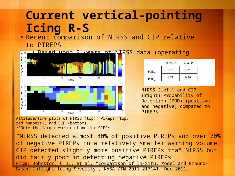
NIRSS (left) and CIP (right) Probability of Detection (POD) (positive and negative) compared to PIREPS.
Altitude/Time plots of NIRSS (top), PiReps (top, red numbers), and CIP (bottom) **Note the larger warning band for CIP**
• Recent comparison of NIRSS and CIP relative to PIREPS• Based upon 3 years of NIRSS data (operating at GRC)
“NIRSS detected almost 80% of positive PIREPs and over 70% of negative PIREPs in a relatively smaller warning volume. CIP detected slightly more positive PIREPs than NIRSS but did fairly poor in detecting negative PIREPs.” From: Johnston, C.J., et al, “Comparison of In-Situ, Model and Ground-Based Inflight Icing Severity”, NASA /TM-2011-217141, Dec 2011.

Current scanning Icing R-S
Sensor Systems
•Radiometrics MP3000A 35 channel Temperature, Water Vapor and Liquid Profiler• 21 channels in K-band 22-30 GHz• 14 channels in V-band 51-59 GHz• Optional Azimuth Positioner• Optional Infrared Thermometer• Located on NASA GRC Icing Research Tunnel balance chamber roof• Vertical and 15 deg slant elevation measurements• Slant measurements made at CLE runway headings• Provides temp profiles and integrated liquid water measurements for vertical
and 15 degree elevations with Radiometrics neural nets
•Radiometrics Narrowbeam Radiometer• Uses Radiometrics’ PR-series receivers• K-band multichannel receiver (21 channels in 22-30GHz)• W-band polarized receiver (89 GHz)• Located on NASA GRC Icing Research Tunnel shop roof• Provides integrated liquid water measurements over all slant angles with
algorithms from Dr. Ulrich Lohnert from the University of Cologne

Current scanning Icing R-S
FEATURES• 1 deg beam widths • Upgraded elevation and azimuth scanning (Moog
Quickset QPT-500)• Integrated Garmin 17 HVS GPS (time) and Vaisala
WXT520 Met (temp, RH, wind, precip)• Rain Mitigation (radiometer lens blower and reflector
hydrophobic coating)
CURRENT PLANS• Install version 3 RadScan software• Install support mod kits
• Changes intended to address operational problems (structure flex, positioner freezes, software bugs)
• Will add tip calibration capability
NASA Narrow-beam Multi-frequency Microwave Radiometer
Developed by Radiometrics, Inc. of Boulder, CO under SBIR and Aviation Safety Program funding