(NASA-CR-163859) FLIGHT EVALUATION OF THE N81 … · objects and reduce noise pollutions. ... gyro...
65
(NASA-CR-163859) FLIGHT EVALUATION OF THE TERMINAL GUIDANCE SYSTEM (California Polytechnic State Univ.) 65 p HC A04/MF A01 CSCL 176 N81-14991 Unclas GRANT NO. NSG-4022 j FLIGHT EVALUATION OF THE TERMINAL GUIDANCE SYSTEM BY DORAL R. SANDLIN CALIFORNIA POLYTECHNIC STATE UNIVERSITY SAN LUIS OBISPO, CA 93407 https://ntrs.nasa.gov/search.jsp?R=19810006476 2018-07-19T09:24:10+00:00Z
Transcript of (NASA-CR-163859) FLIGHT EVALUATION OF THE N81 … · objects and reduce noise pollutions. ... gyro...

(NASA-CR-163859) FLIGHT EVALUATION OF THETERMINAL GUIDANCE SYSTEM (CaliforniaPolytechnic State Univ.) 65 p HC A04/MF A01
CSCL 176
N81-14991
Unclas
GRANT NO. NSG-4022j
FLIGHT EVALUATION OF THE
TERMINAL GUIDANCE SYSTEM
BY
DORAL R. SANDLIN
CALIFORNIA POLYTECHNIC STATE UNIVERSITY
SAN LUIS OBISPO, CA 93407
https://ntrs.nasa.gov/search.jsp?R=19810006476 2018-07-19T09:24:10+00:00Z

TABLE OF CONTENTS
Page
I. INTRODUCTION 1
II. TEST EQUIPMENT 3
Terminal Guidance System 4
Support Avionics 6
Data Recording System 6
III. TEST DESCRIPTION 7
IV. RESULTS AND DISCUSSION 8
Comparison of Straight-In ILS and Curved Approaches ... 9
Effect of Pattern Geometry 9
Effect of Pilot Experience 11
Pilot Comments Concerning TGS 12
Effect of Mind and Turbulence 13
V. CONCLUDING REMARKS 15
REFERENCES 59

LIST OF FIGURES
Figure Page
1. Interspersed Curved and Straight-In Approaches 17
2. Curved Approach Mechanization Scheme forDFRC Flight Tests 18
3. Terminal Guidance System Block Diagram 19
4. Test Aircraft (Cessna 182) 20
5. TGS Computer 21
6. Placement of TGS Control Head on Instrument Panel 22
7. TGS Control Head 23
8. Heading Error Equation 24
9. Glideslope Equation 25
10. In-Flight Recording System USNA 1980 26
11. Flight Paths for Various Turn Angles 27
12. Summary of Approaches Flown 28
13. Cooper Ratings 29
14. Pilot Ratings for Conventional ILS and CurvedApproach Tasks 30
15. Effect of Pattern Geometry During CurvedApproaches (Turn Radius) 31
16. Effect of Pattern Geometry During CurvedApproaches (Glide Slope) 32
17. Effect of Pattern Geometry During CurvedApproaches (Turn Angle) 33

IV
Figure • Page
18. Effect of Pilot Experience During Curved Approaches(3° Glide Slope, 1853 M Radius) 34
19. Effect of Pilot Experience During Curved Approaches(6° Glide Slope, 1853 M Radius) 35
20. Effect of Pilot Experience During Curved Approaches(6 Glide Slope, 914 M Radius) , 36
21. Cross Wind Effects 37
22. Curve Fit -'Run #3 38
23. Curve Fit - Run #5 39
24. Curve Fit - Run #8 40
25. Computer Constructed Curve - Run #9 in Three-DimensionalSpace 41
26. Over head Projection of Computer Constructed Curve -Run #9 42
27. Glide Slope and Heading Errors for Computer ConstructedCurve - Run #9 43
28. Computer Constructed Curve - Run #3 in Three-DimensionalSpace 44
29. Overhead Projection of Computer Constructed Curve -Run #3 45
30. Glide Slope and Heading Errors for Computer ConstructedCurve - Run #3 46
31. Computer Constructed Curve - Run #5 in Three-DimensionalSpace 47
32. Overhead Projection of Computer Constructed Curve -Run #5 48
33. Glide Slope and Heading Errors for Computer ConstructedCurve - Run #5 49
34. Computer Constructed Curve - Run #11 in Three-DimensionalSpace 50
35. Overhead Projection of Computer Constructed Curve -Run #11 51

Figure Page
36. Glide Slope and Heading Errors for Computer ConstructedCurve - Run #11 52
37. Computer Constructed Curve - Run #8 in Three-DimensionalSpace 53
38. Overhead Projection of Computer Constructed Curve -Run #8 54
39. Glide Slope and Heading Errors for Computer ConstructedCurve - Run #8 55
40. Computer Constructed Curve - Run #15 in Three-DimensionalSpace 56
41. Overhead Projection of Computer Constructed Curve -Run #15 . 57
42. Glide Slope and Heading Errors for Computer ConstructedCurve - Run #15 58

INTRODUCTION
The operation of aircraft in a terminal area has been studied
recently with the objective of identifying and finding solutions to the
problems associated with heavy traffic maneuvering in limited airspace.
Presently, aircraft arriving in a terminal area are vectored along a
straight, shallow flight path to a landing. These approach paths are
frequently over congested metropolitan areas and result in noise pollu-
tion and increased hazards both to people in the aircraft and on the
ground. The approaches are long and require considerable time and use
of fuel as well as necessitate an inefficient mix of low and high speed
traffic. In some cases, terrain prevents straight-in approaches with
shallow glideslopes. Therefore, the need has long existed for an
alternative to the shallow-glide, straight-in approach.
The recent 'introduction of STOL aircraft into service creates
new and magnifies old operational problems. These aircraft which are
capable of providing increased commercial transport between large cities
will be required to operate in limited, nonallocated airspace pene-
trated by tall buildings where noise pollution is particularly objec-
tionable. A large number of terminal operations is required of the
STOL aircraft for it to be economically viable, and speed incompatibility
with CTOL aircraft causes delays and congestion.
The recommended use of curved steep approaches to solve or
alleviate these problems has been made in many of the studies conducted.

2
Steep, curved approaches permit the routing of traffic around or, at
relatively high altitudes, over critically populated areas and tall
objects and reduce noise pollutions. A more efficient mix of slow
and high speed traffic (see Figure 1) can be obtained with improved
airspace utilization in the terminal area. More direct routing is
also possible using curved approaches resulting in both reduced fuel
costs and travel time.
Guidance along a descending curved path can be achieved with
the microwave landing system. A great deal of time and money has been
spent on studies, plans-development, hardware production, and flight
tests to identify operation problems and evaluate the system. The
microwave landing system should be operation by the mid-1980's.
The Langley and Dryden Flight Research Centers of NASA have
conducted flight tests and studies designed to obtain a better under-
standing of problems associated with curved approaches. In 1971, the
Dryden Flight Research Center (DFRC) conducted a flight test to inves-
tigate the feasibility of flying IFR curved landing approaches. These
tests utilized a twin-engine, general aviation aircraft with a ground-
based radar, computer, and transmitter in an arrangement shown in
Figure 2. The aircraft's position was measured by radar. The approach
geometry was stored in the computer where a comparison between the
aircraft's position and a set of preprogrammed coordinates corres-
ponding to the curved approach corridor was made and position errors
generated. Flight path errors were transmitted to the aircraft through
a data uplink and displayed on an ILS indicator. These tests led to
the development of a system contained onboard the aircraft called the

3
Terminal Guidance System (TGS) which also gives guidance along a
descending flight path to landing, but uses only the ground based
VOR/DME station. The TGS was patented by DFRC and fabricated by
Progress Aerospace Enterprises, Inc. A grant was made to the Cal
Poly Foundation at San Luis Obispo for the flight evaluation of
TGS.
The objectives of the evaluation were to:
1. Compare ILS straight-in and TGS curved approaches.
2. Determine the effects of pattern geometry on system
performance.
3. Determine the effects of wind and turbulence on system
performance.
4. Determine the effects of pilot experience on system
operation.
The purpose of this report is to present the results of the
fl ight evaluations.
TEST EQUIPMENT
The TGS consists of an analog computer unit with a control
head. The computer is connected to the altimeter, RMI, DME, and
gyro compass. Since the aircraft electrical system provides 12 volts
dc and the altimeter requires 28 volts dc, a 28 v dc power supply was
required. A 28 to 15 volt dc to dc converter was needed to provide
power for the analog amplifiers in the circuit of the computer. In
addition, a small amount of 26v 400 HZ synchro power was needed
for the synchro converter references of the Gyro Compass and RMI,
and also for an internal function module.

4
The TGS and the associated support equipment was connected as
shown in the block diagram given in Figure 3. The equipment was in-
stalled in the Cessna 182 aircraft shown in Figure 4. Figure 5 shows
the placement of the computer on the floor of the aircraft behind the
right front seat. Figures 6 and 7 show the placement of the control
head on the instrument panel.
Terminal Guidance System
The Terminal Guidance System is a vehicle-borne navigation
approach guidance computer which gives guidance along a curved descend-
ing flight path to a termination point over a VOR/DME Station. The
aircraft arrives over the terminal point on a selected heading and
altitude by flying along the surface of an inverted imaginary cone
half-angle of 90°-9. , where 9. is the guideslope angle selected
by the pilot. The system consists of a computer, control head, and
the support avionics. The support avionic includes an altimeter,
DME, gyrocompass, and RMI which provides aircraft positional data in
three-dimensional space. The termination point heading, altitude,
and a wind correction angle are selected on the control head and are
also provided as inputs to the computer.
The computer provides an analog solution in the form of head-
ing and glideslope error angles by solving the following equations:
'• 9eh ' 29vor - Vo - 9rw * 8wc * 360°-
9 = magnetic runway heading selected on control head.
9..,, = wing correction angle selected on control head,we
9 = magnetic heading of aircraft obtained from gyro-gy compass.

9 = magnetic bearing of aircraft from station obtainedvor from RMI.
Q . = heading error which is the difference between theaircraft heading and the tangent to the optimalflight path. See Figure 8.
9eg = 9des - arctangent " ht> .
9. = glideslope angle selected on control head.
h = absolute altitude obtained from the altimeter.
h. = desired altitude over the termination point selectedon the control head.
d = slant range distance from the aircraft to VOR/DMEStation obtained from DME.
9 = glideslope error which is the difference between9 the selected and actual glideslope angles as shown
in Figure 9.
Either these error signals or the signals plus their dif-
ferential are displayed on an indicator similar to an ILC indicator.
The option of including the differential term is provided to minimize
pilot overshoot. If the pilot flies the aircraft so that the two
needles are centered, the error angles will be equal to zero, and
the aircraft will fly along the desired flight path arriving over
the termination point on the selected heading and altitude. This
system used in conjunction with an R/NAV system which permits the
offsetting of the VOR/DME Station can be used to fly curved approaches
to a landing on any airfield in the vicinity of a VOR/DME Station.
For a more complete system description see Reference 6.

Support Avionics
The avionics necessary to the TGS includes an altimeter, RMI,
DME and Gyro Compass. A list of the types of support avionics used
follows:
1. Altimeter-Datametrics - Model 1300 Pressure Transducer:This altimeter provides 0 ± 5 VDC for 0-15 psi.Forstandard pressure at 0 ft. mean sea level, an output of4.847 VDC will result. At an altitide of 5000 feet, anoutput of 3.916 VCD will result and a linear variationbetween these altitudes is assumed. A modification ofthe TGS circuitry was made to include a null system.This system will allow adjustments to account for pre-vailing barometric conditions and different airfield ele-vations.
2. DME - King Kn 65: The DME provides nominal voltages of0.000 to 0.400 VDC for a distance of 0 to 10 nauticalmiles. Since the TGS was designed for use with a KingKn 60 which provides different nominal voltages, it wasnecessary to modify the TGS circuitry so the Kn 65 couldbe used.
3. Gyro Compass - Narco HSI-100S.
4. RMI - King KNR 660 VOR/LOC Receiver.
Data Recording System
Data was recorded on each run by the safety pilot using the
Cooper rating system. For several approaches, a portable strip chart
recorder was used to record the heading and glides!ope error signals.
The results obtained were not satisfactory, so a new data recording
system which records four times a second was fabricated and installed
for fifteen approaches using two different pilots. Figure 10 shows
a schematic of the data recording system which essentially consists
of an intel SDK-80 microcomputer, a multiplexer, and an audio tape
recorder. The synchro outputs of the gyro compass and RMI are con-
verter to D.C. voltages using a synchro to D.C. converter. These

7
two voltages plus the D.C. voltage output of the altimeter and DME were
recorded on tape. In addition, the voltage outputs of the computer,
which are the heading and glideslope error signal, were recorded.
TEST DESCRIPTION
Curved approach patterns with 0°, 90°, and 180° turns were
flown as shown in Figure 11. A turn radius of one nautical mile was
used for the 0° and 90° turn approaches. Nominal turn radii of 557
meters (1500 ft.), 414 meters (3000ft.) and 1833 meters (6000 ft.)
were used for the 180° turn approaches. For most of the approaches,
a turn of 180° was used since there was no significant difference in
the approaches of different angles except length of time spent on
the flight path. Approach entry was made using a combination of
ground check points and the VOR/DME display. Glideslope angles of -
from 3 to 9 were used, and three pilots with instrument flying time
from 200 to 600 hours flew graded approaches. Wind directions were
directly opposite and 90° cross wind to the termination heading with
velocities varying from 0-20 knots. Turbulence varied from calm to
moderate. Four different VOR/DME stations were used. Most flights
were made under simulated instrument conditions wtih a safety pilot
to record data and spot other aircraft. A data recorder that records
on magnetic tape all inputs to and outputs from the TGS computer was
used for fifteen approaches. All approaches were made at 90 mph
indicated air speed and several flap settings were used to determine
preferred aircraft configuration.
The glideslope error needle becomes extremely sensitive and
difficult to follow when within 1/2 m. DME distance from the station.

8
To eliminate the need to track the glideslope when very near the sta-
tion, minimum altitudes of 200 ft. for 3° and 400 ft. for 6° glide-
slopes were established. The altitude minimums allowed pilots to
discontinue tracking the glideslope at approximately 1/2 n.m. from
the station. This is less than the distance between the ILS glide-
slope signal generator and the point where it is no longer necessary
to track the glideslope. Usually, the ILS glideslope signal generator
is placed on the end of the runway opposite touchdown. The localizer
needle was tracked without difficult until over the station.
See Figure 12 for recapitulation of approaches flown.
RESULTS AND DISCUSSION
The results of the TGS flight evaluation program are included
in Figures 14 to 42. The Cooper rating system shown in Figure 13 was
used by the pilot to rate each approach, and the safety pilot evaluated
the ride quality. Fifteen approaches were made using the package that
recorded on tape all inputs to and outputs from the computer. The
tapes were inserted into a computer graphics system, and graphs were
made of the actual flight path in space. A computer program was
written to construct the zero-error, no-wind flight path, and the
two paths were graphically superimposed for easy comparison. An
overhead flight path projection was made as were graphs showing glide-
slope and heading errors as functions of DME distance. The DME signal
to the TGS contained considerable noise as shown in Figures 22, 23,
and 24. It was necessary to smooth this data using a least square
curve fitting technique before the data could be used for the graphs.
Several of the resulting graphs are shown in Figures 24 through 42.

Comparison of Straight-In ILS and Curved Approaches
Figure 14 presents a comparison of pilot ratings for curved
and straight ILS approaches with the turbulence level varying from
light to moderate. The ILS approaches were flown by pilots at the
DFRC and this data is published in Reference 6. All approaches
recorded in Figure 14 were flown by the same pilot. A glides!ope of
6°, and a turn radius of 1833 meters, and a turn of 180° was used
for the curved approaches since they were not significantly more
difficult to perform than the 3 glideslope approaches for this par-
ticular pilot. Figures 27, 30, 33, 36, and 38 show flight data that
reveal how accurately the glideslope and heading guidance can be tracked
for several different turn radii and glideslopes.
The conclusion drawn from this data is that curved approaches
of the type flown are no more difficult to fly than straight ILS
approaches.
Effect of Pattern Geometry
Approaches were flown to determine the effect of varying turn
radius, glideslope, and turn angle. Figure 15 compares the pilot
ratings for approaches using 180 turns, 6 glideslope, varying turbu-
lence level, and turn radii of 457, 914, and 1853 meters respectively.
These approaches were all flown by one pilot who had 500 hours of
instrument flying time and was the most experiences with the TGS.
Although several approaches were flown using a turn radius of 457
meters of 1/4 n.m., approaches that start within 1/2 n.m. of the sta-
tion are impractical since the published accuracy of the DME equipment
used is - 1/2 n.m.
10
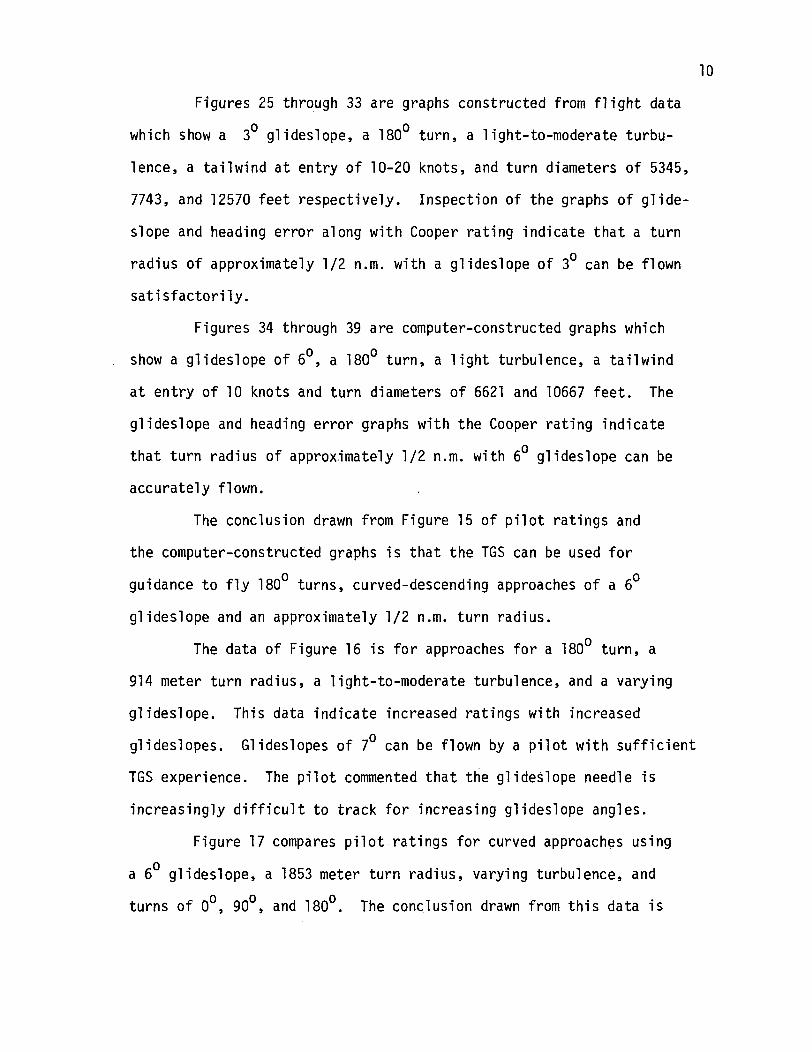
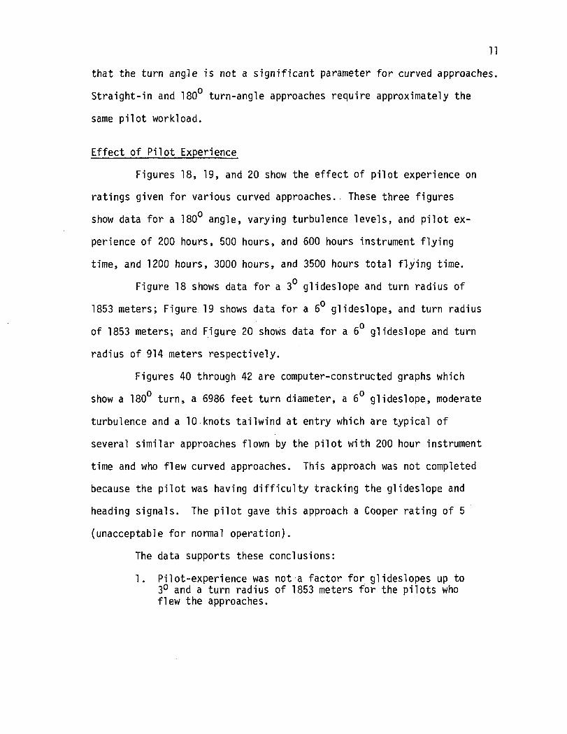
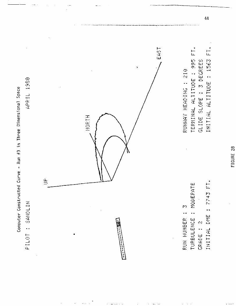
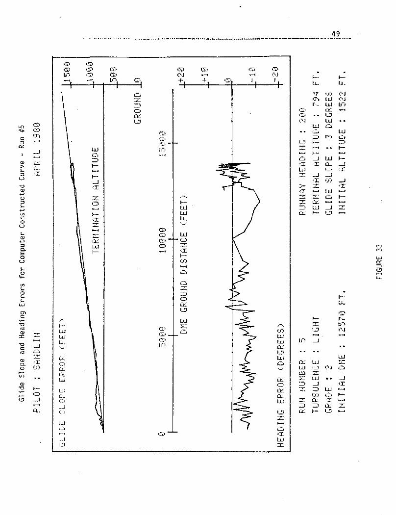
Figures 25 through 33 are graphs constructed from flight data
which show a 3° glideslope, a 180° turn, a light-to-moderate turbu-
lence, a tailwind at entry of 10-20 knots, and turn diameters of 5345,
7743, and 12570 feet respectively. Inspection of the graphs of glide-
slope and heading error along with Cooper rating indicate that a turn
radius of approximately 1/2 n.m. with a glideslope of 3° can be flown
satisfactorily.
Figures 34 through 39 are computer-constructed graphs which
show a glideslope of 6°, a 180° turn, a light turbulence, a tailwind
at entry of 10 knots and turn diameters of 6621 and 10667 feet. The
glideslope and heading error graphs with the Cooper rating indicate
that turn radius of approximately 1/2 n.m. with 6° glideslope can be
accurately flown.
The conclusion drawn from Figure 15 of pilot ratings and
the computer-constructed graphs is that the TGS can be used for
guidance to fly 180° turns, curved-descending approaches of a 6°
glideslope and an approximately 1/2 n.m. turn radius.
The data of Figure 16 is for approaches for a 180° turn, a
914 meter turn radius, a light-to-moderate turbulence, and a varying
glideslope. This data indicate increased ratings with increased
glideslopes. Glideslopes of 7 can be flown by a pilot with sufficient
TGS experience. The pilot commented that the glideslope needle is
increasingly difficult to track for increasing glideslope angles.
Figure 17 compares pilot ratings for curved approaches using
a 6 glideslope, a 1853 meter turn radius, varying turbulence, and
turns of 0°, 90°, and 180°. The conclusion drawn from this data is
11that the turn angle is not a significant parameter for curved approaches.
Straight-in and 180° turn-angle approaches require approximately the
same pilot workload.
Effect of Pilot Experience
Figures 18, 19, and 20 show the effect of pilot experience on
ratings given for various curved approaches.. These three figures
show data for a 180 angle, varying turbulence levels, and pilot ex-
perience of 200 hours, 500 hours, and 600 hours instrument flying
time, and 1200 hours, 3000 hours, and 3500 hours total flying time.
Figure 18 shows data for a 3° glideslope and turn radius of
1853 meters; Figure 19 shows data for a 6 glideslope, and turn radius
of 1853 meters; and Figure 20 shows data for a 6° glideslope and turn
radius of 914 meters respectively.
Figures 40 through 42 are computer-constructed graphs which
show a 180° turn, a 6986 feet turn diameter, a 6° glideslope, moderate
turbulence and a 10 knots tailwind at entry which are typical of
several similar approaches flown by the pilot with 200 hour instrument
time and who flew curved approaches. This approach was not completed
because the pilot was having difficulty tracking the glideslope and
heading signals. The pilot gave this approach a Cooper rating of 5
(unacceptable for normal operation).
The data supports these conclusions:
1. Pilot-experience was not a factor for glideslopes up to3° and a turn radius of 1853 meters for the pilots whoflew the approaches.

12
2. Pilot-experience is a factor for a 6° glides!ope and ap-proximately 914 meter turn radius. The pilot with thelowest instrument and total flying time gave the highestpilot ratings and had difficulty flying the approaches.
Pilot Comments Concerning TGS
Several pilot comments on and opinions of the TGS were given.
One pilot commented that he thought better situation information was
needed; another pilot felt that enough situation data was available,
but the instruments displaying the data was not optimally arranged for
easy use. Figure 6 shows the arrangement of the instrument panel.
An integrated display which indicates the aircraft heading, altitude,
DME distance to the VOR station, and the localizer, and glideslope
errors would be an improvement. Pilots commented that initially a
banked referenced condition necessary to hold a curved flight path
presented some difficulty since they were accustomed to a wings-level
reference condition for ILS approaches. Several approaches were flown
before adjustments were made.
Because of the geometry of a curved, descending approach, the
descent rate necessary to remain on the glideslope varies throughout
the approach. Low descent rates are necessary initially, but higher
descent rates are required for the portion of the flight path nearest
the termination point. For a ground speed of 90 mph and a glideslope
of 3 , the rate of descent varies from 0 to 415 fpm. A constant ad-
justment of power is necessary to hold airspeed. Pilots commented
that while this condition was not difficult to deal with, it was
bothersome and increased pilot workload. Pilot comments support the
conclusion that the presence of turbulence increases the workload re-
quired for curved approaches.

13•:
The safety pilot evaluating each approach for ride qualities
commented that the curved approaches with glideslopes up to 6° were
comfortable. His opinion was that because of high rates of descent,
steeper glideslopes would be somewhat uncomfortable for the passenger.
Effect of Wind and Turbulence
The system was not designed to maintain a given track in the
presence of wind. But it was designed to bring the aircraft to a
terminal point with the appropriate flight conditions to proceed in
a straight path to the runway, which it does. However, useful infor-
mation concerning the system capabilities can be gained by evaluating
the effects of wind and turbulence on the performance of the system.
To determine the effects of winds, curved approaches were flown
using 180 turns in calm-to-moderate turbulence conditions, varying
glideslopes, and turn radii. It was observed that the bank angles
needed to hold a given turn radius increased in the down-wind portion
of the turn, and decreased in the upwind portion. The change in bank
angle is required to compensate for the group speed change caused by
winds. Steeper bank angles are required whenever the group speed
is greatest. This effect was measured and reported in Reference 6.
While the variation of bank angle will compensate for a variation of
ground speed due to winds, it does not compensate for wind drift.
Figures 26, 29, 32, 35, and 38 show the effect of wind drift caused
by a direct tailwind at flight path entry. When viewed from above,
the no-wind zero-heading error TGS generated flight path is a circle
that passes through the approach entry point and is tangent to the
runway heading at the terminal point. As indicated, the actual flight

14
path is downwind of the "no-wind" flight path. These figures were
computer-constructed from recorded flight data. The TGS does not
correct to a given flight path over the ground or for drift caused
by direct tail or head winds.
The TGS provides a wind correction control which slightly
offsets the desired runway heading to correct for cross-wind. To
use this capability, the pilot must calculate and select the desired
wind correction angle. The wind correction switch is set to the
direction of the wind across the runway, i.e.; for a wind moving from
the left across the runway while facing the direction of the landing,
the switch is set to L (left) position and the correction angle is
selected. The runway heading is decreased by the amount selected.
Figure 21 shows the flight paths that would result for a no-wind
and no-correction, no-wind with cross-wind correction, and a cross-
wind with cross-wind correction conditions. The wind correction con-
trol setting results in increased separation of the actual flight
path from the no-wind and no-wind correction path for a 90 turn and
reduced separation for the 180° turn flight path.
Several 180° turn approaches were flown with and without wind
correction angles and 90° left cross winds of 15 knots. The aircraft
drifted to the right of the flight path near, the termination point and
arrived over the termination point on a heading less than the runway
heading by about 10 . The wind correction of left 19° caused the air-
craft to cross the termination point on a heading approximately 20° less
than the runway heading. It can be concluded from the wind effects
tests and analysis that the TGS will not correct to a given path over
the ground. Wind drift causes considerable deviation from a given

15
ground path. For 180° turns with a cross wind, the wind correction
control reduces deviation for 180 turns, but increased it for 90
turns. For aircraft required to maneuver in limited airspace or along
a given flight path in order to avoid ground objects, the inability
of the TGS to correct to a given path over the ground and adequately
compensate for wind drift could limit its use.
CONCLUDING REMARKS
The purpose of this study was to evaluate the terminal guidance
system. The TGS is avionic equipment which gives guidance along a
curved descending flight path to a landing. A Cessna 182 was used
as the test aircraft and the TGS was installed and connected to the
altimeter, DME, RMI and Gyro Compass. Approaches were flown by three
different pilots. The conclusions drawn from these tests are:
1. When the aircraft arrives at the termination point, itis "set up"'on final approach for a landing.
2. The TGS provides guidance for curved descending approacheswith glideslopes of 6 which required, for experiencedpilots, workloads that are approximately the same as foran ILS.
3. The glideslope is difficult to track within 1/2 n.m. ofthe VOR/DME Station.
4. The system will permit, for experienced pilots, satis-factory approaches with a turn radius as low as 1/2 n.m.and a glideslope of 6 .
5. Turn angles have little relation to pilot workload forcurved approaches.
6. Pilot experience is a factor for curved approaches. Pilotswith low instrument time have difficulty flying steep ap-proaches with small turn radius.
7. Turbulence increases the pilot workload for curved ap-proaches.

16
8. The TGS does not correct to a given flight path over theground nor does it adequately compensate for wind drift.
The TGS will provide accurate guidance for curved descending
approaches which can be followed by pilots with reasonable low instru-
ment time. However, the inability to correct to a ground path and
for wind drift will limit its use in airspace where deviation from a
given flight path is critical.

17

LU
LUH-
h-S ILJU O
= .1]O LLcn
oor
z u.
^ £z
oLLI
XO<oDCQ.Q.
QLU>cc13U
ccoCOc/>zcc
be:znQ.D
OQ
A
ccoccccLU
zoH
OQ.
CM
UJ
o:
ou.
IDO.
OO
_

"3r-l
~Q)
•X3D
D
O 0)
tnW ^<!U C
•H -rl
Q.D. O
>-i OO -l-l0) CN
< a•H_3
19
C£l
60C•rl-o
3 4J
(U CJr-l C 13to o an) »-i C -rt
O O 4J0) (1) -rl rHa. v< u «O VJ O
t-H O <U T3CO O M Q)
0)D.Oi-l
COQ)
•rl•o
*O *O *"OM -rl C
H -O 0)3 O)-i G 60
O -H .CU) 4-1 r-l U
O
Ma)
C *O 5 --. -rl Ord tn 00 ^ v-i
O 4 J 4 J «J B CO >-l Xw O O t l l O M T ^ d ) O
a j c j i - H o J a i T J c u 4 jDil-HrH 00 r—I S CO "O JJ -rt
- - . c u < i ) e c i > o a > o a > 3S t o c o c d t o p L i j c Bto to
M
oo
Oo
inoH
Ho
Ni •»-f^ U-4
a)o erfo<r
SoO
> o-CM
r
OC )JtN 0)
4-1
O V4J (1)
> CCM O
4Jr-to n)
<J «->CM VJ 4Jt-1 -rl Ifl
< ca
«UJ
ac
COrvl
60 IT)C ^O•H «
^§
M
X•it
u-r-l>-<
•H pj4-1 Ur-l (0< Q
OO OM r-l>, MO w
SC •"4-1
O 0)o erf
Oo enV4 tno a)
CJ-a
c•H o rt o
o oV4 0)

VJ
,C
iri/i0)
u

\

cu
0)
i.
(J->
co
T3
JOJ
O
4-)eo
LT)CD

OP JV'CW

24
UJ
o
OLU
trODCDCLU
O
LUX
^•sj
ccOz
Ul
so z
ott <o H> 0)
<$z3CC
co
o >-oo
1 ore* .T >«1 a
* xiO = £< oc $
S; ! SO CD O
00
IUocDO
o
•\. /"-C
s^~
x*"
//
5W
O
yN
0CM
11£
-- L <D7
He
ad
ing
O<
co
« 2
Z Eo> o.« i-r" u-LL
O Oc0)0)50)
OQ
5o>c
Vo
S
•oc
D)Ck_
(DO
CO
o>
o

25
zo
OUJ
UJQ.O_jCOLUQ
-JO
CM
CM
JCO)
'oX 0a
•2 o_ 0
ucatoQ 0
UJ -2s EO <
v x:
—oQ.
Co•••(0
Term
in
JC
(9ao
Glid
es
o
(002
5•o
De
sir
e
ft•3cr
k.UJ
0ao
Glid
es
o>o0
O)
UJEC
OiZ
CD
I(t) «0
o
ct?II II
O)«j»
O)
o

CD IC -4->
•r- S-"O to CD5- (J CO T-O <J >>CU -r- 03S_ 4-> r-
Ol Q." C tO
CJ) CD'i—C to -O
O O C• — O (OCU CO> I •— ~ toCU CJ CU 4->
X> Q CDi —X3 3
S- C >i- l/>O O S_ O)
M --- - S-
1 1
cu4~>4-> OCU -r-IO "Oto 3(O eC
CU 4-*TQ C/)
i- T-
O 1—
O rescu cu
oCO
DC1—CJ
ui"I 3
TJ fc'*, 0>o -p<-> lr0> Os_ o
0)" STex
o c-!-> Oto
S- -U(O C4-> Ooo o
^^co<O
T30
i-0
4-><O
^0ecu
« cc: o i—
•i- S_ LDe -M oC ^ ^j-QJ C1J
CO>-CO
es
oCJUJ
L J00CTi
COID
O
4->Coo
cuc
U
CO
<U r—
O) Orv » _ r
5-CU O
4-> CO3 I
E QO CO
oCJ
o00ooo
O 'o: i
Q.CJ
i.O -MQ. S_
Oi— a.O)
: t- s.: res <D
Q. toCM r—
Q.Q.3
CO
i-cuoa_
cu tor— O)o -i->^ t-o cuO 4J-I-J •»->o <a
CM
OTD
CM
I
CM
CD
o
co
5-oa.
CNJ
cvi
i
4-> Oi_ -r- tncu en s- coX •<- <DCU Q +-> Cr- S- SD. O CU O
•r- -M > S_•*-> C CO«— CT O3 o cj s_
<T3
<CCO
>LO
CO
CUC
ra O: to
CJ O!
o •<-(Oa CM03 r—
4J (_}3 OD.
' C l/l•r- 4->
to Or— >
O O4J r—
0.+ I
cu
CJ OJQ >
o oQ CJ
toi-o4->(O
a>cu
O 4->
C SO CO

UJ
Oz 27
DCDH-
LU_lO
DCIDH
ODC<
OCOu.
</)X
<Q.
IO
HI_JOz
zDC
b

28
SUMMARY OF APPROACHES FLOWN
GLIDE SLOPE
00 ANGLE
90° ANGLE
180° ANGLE1853 M RADIUS
180° ANGLE914 M RADIUS
180° ANGLE457 M RADIUS
180° ANGLE1853M RADIUS900 CROSS WIND
TOTAL
30
6
13
43
20
15
230
4°
3
50
1
60
6
8
23
25
5
15
70
4
8
80
3
5
13
go
4
10
Pilots Schlein Sandlin HewettInst. Time 200 hrs 500 hrs 600 hrs# Approaches 23 137 35
FIGURE 12

FT-13R-6929
COO
ccUJQ.OOO
Sg
§1oui
ill•5 in n.IZ CO *>
o
2O
o.o:ot/>IU
< O
- £Qi K*lij <(^ C
UJ> 0t- ?Siss «<
0 g
— ot; H** _.CC Q
^ ^% 0O 0
to to toIII UJ UJ
> • > • > •
to to toUJ UJ UI
*~
Q_J
u/ "i? . ^7 J_
i CC
°5 lS
EX
CE
LLE
NT
, IN
CLU
DE
!G
OO
D, P
LEA
SA
NT
TO
SA
TIS
FA
CT
OR
Y,
BU
TU
NP
LE
AS
AN
T
CH
AR
,
— Cvl (O
C£O
ito
s
— J o»i Hs«iuj
o
to to toUJ UJ 111>- >- >-
3 D
to t tIII " «"~
*_ Q Cu
8 8Q 0
§ §
*~ £ -* i SOto JjJ <3< Q. <jUJ O .
7 ^ ^—* COx i 5n^ ^ ^—
AC
CE
PT
AB
LE,
BUT
XVC
HA
RA
CT
ER
IST
ICS
UN
AC
CE
PT
AB
LE
FOR
AC
CE
PT
AB
LE
FOR
Ef
ON
LY1
tf Irt tD
a
og
iD
0^22UJ 1-tD <o: a:UJ UI? O-uj o
1
§= 'g iOH- ^ ^0
o o oZ 22
Oy1>J UJ0 Ij
UJ g5 5UJ to j
3 O
2 £ g2 15 0
UN
AC
CE
PT
AB
LE
EV
EC
ON
DIT
ION
1
UN
AC
CE
PTA
BLE
-D
Ar
UN
AC
CE
PT
AB
LE-U
NC
r- eo o
uo
o.UJoo
• <t2O
g
o2
3:oDoUI
t l-Js^1 **
2^> UJ
MO
TIO
NS
P
OS
S18
LYT
O P
RE
VE
NT
PIL
OT
O
OXft.oCC
w? .<u
2O
c"i H-Z CC
UICLO
to
UJ5to
h-5
<
UJo:

30
GOXX
GO
CODMQ
CO
o-.'.Q_
GOI
O
UJ
o
ce:CD
ooCD
CD
ou
ww reM £, O P-:
o ft & o(.^ ^ £J ;'1Q t "j
< CO & O 00?.; tii vfM P < QEH M g M2 i-5 Q .-3MO W f*l O
U
O
00 orH VO
O"Z
EHO.-3
w
wQ
i
O —M.J
I I I I
a:
EH2 DH WS OHW M> Do aPS ugM
EH2W Qs: MW PH> HO COpc; yp, Q
gH
PHOEHO<c[:(
WH
EH
CO

sCO
31
U
GOUJ
( )
olQ_<c( )UJ>~~>c_>CD
^ CO
^D Ma a
wEH,-lj
Qos1a; o
HH tHrtj 1
EHS as< HU TM
o ®
MW i-3t^ tjO K
CO @2; S»
M S ^Q Q (SM EH r"S[ "] V^O o r\
o Qo co O ®
<Ot@e
,ocx>ou>— •
COinCOrH
oooro
OUJCO
«=cc_
DE-i
O
O
MEH
Di
oom
r-m
_L_J I L
Ot-qHa. Q Q
O
EH
W
O
HCOWQ
EH2W
W
O
u
COMEH
CO
H

t /^C/JUJ
Do
o_
GU.I
O~~»*T>C^J
, , rf ro»•"•< I-M
rr> o
>-h- QUJ HI
f* r n
O2Wt-JJ3
§DEH
W
rtj
WQOs
rV r\m ^/
•••C i
s~* ~--ih C."< M
U ^
O ®
wD ^ 8>
W ^ ®
| 0 | I
g M O O Q
;EH r:
Oi0
oH
O
0
o>
0
CO
o Qo ^" Oco ^ X
8§or-
i
i© ©^ _ j ( •o O o
0
32
UJ
UJ
<CD_
H I i i i i i i i VP .^v
o
o;Z3CD
UJ
HO
H
a3MDO[JOH
EHIS
*v(
tuJ>OOH
M
Q
§HV)WQ
FH» "
§yo&CMsM
jvl(X0E-iU
MlHEHrtjCO

33
cou.1re<roC£iO_y-\L~L«.
<cf~*lUJ
ry*~~i(__>
CO—^p»
Q o2
"~" rij
1 — 2UJ Pi
O C_jCH
LU —CD
HU2W
ff\
§3EH
W
rfKWQ
s1« o
M EHft, 1
EHS 55J O< MU 1-1
O ®
w(i,0
enwQH
O
oVO
MQ
s -EH*PM
o
oVD^*
sro ®in WCO >< jfii§ — I ^^
^S®
@ ®§ $
^22EH
oOoorH
Oo
LU
Q_
CD
u2H !C_J 'Z.T -^— _
cd oI^n
EHO
Hd,
© ® §I • I I I i i i i
c > o o r - v o i n ' 3 ' m r > i i H
P
sMDO
2EH2W5lw£>oOnCM
H
Q
§
COWP
EH2WSWJ>OPHCMaH
XOSoEHU|CjJ
CHCOHEHrtjW

TU
RB
ULE
NC
ECODM »,_.-... —..,...,..« . _. - _ — — __— .
Q
3
M MEH EH
H <tiCO t-ia o
E
(_j<cf^\oiQ_ .OU«=C( — •)1 1 1>QC—
^ j
2§§QUJC_J
sUJQ_XUJ
CD
0_
LJ_CO
1 —
I_ULJUU_UJ
<C W EHK W >-l CMW ft UQ O Z 0O r-3 <C CO -
S CO 0i 2 vo as
P^ O W PS "*" ^SH EH Q D |S
EH i— 1 ®S re o o m O ©i-3 u o m Q O< ; H O O O C O O o ©U J ^ ^ H - H M W r s
O 9
<jb ^® OQ OCO {>
88®tfS"Wi
2: (Si ^ S8i \Sf \*v xo"|rj I 1 1 1 1 t 1 T 1
CO COPH OH
re re0 0C 0vo in
CO CO
rc re0 Oo oin o
co co
x re0 00 0
rH
t"1
rH «.
EH0
Mft Q Q
H MD CO JHa w «W Q OPS EH
EH UEH 2 rtl2 W CnW S COa w MW > EH> O <O « COOS ftft s:a HH
CO
IDCO

GOUJzrr< •>e- J
( — •>rv;ex.r-\i L i
LU>
~~*t j
<^3
*••",or^DC~1
UJCJrf5^UJ
UJQ_X
wu3W.-}D
§mDEH
WEHrt*r£wQoy>a»1
« OH E-t
g-tS E^1 O< Hu K?
O ®
\
w w
COD
Q
3,-»
W EHW hi t<ft O0 ?3 0
W f~i%H^ •— — — ^
§ ^
~^
Q DH EH StU o ro
o in0 CO CO
§ @@
{55@
OWOt iW
0 ®
S SH H
• JEH <rtCO E-*S^ OM £H
CO COK p;K IT!
0 00 0vo m
M
CO CO
w ao o0 0m o
ro
co co
o_LI-CD
HEH
CTi
o:^>cs
o oo o
u_U-uu
QgHDOpjPH
EH2Wawo&H
Q
HcowQ
EH2Waw0
ftH
JHffl0EH
rtjhCOHEHrfjCO

36
GOLU
Q_
LU
CJD
P5M<csv_5f£
u
O
TE
T
UR
BU
LE
NC
E
£?VM
WOO***1oEH
EHKOM
^
©
MOiO
CO
WQM,.3
O
o10
wMCO2
2
DEH
oOoorH
RA
DIU
S,—
EHfrj
Ooom• --
a
r-lCT»
M MEH EH
LU
LUC_X
O
Q_
U_CD
h—
I_Ui «
Li.LU
o
O
EHO
H
I I I I
O ®o ®o o
WU3
oooovom
co
o oo oin o
n
to co
o oo oCN OJ
rH
OCM
H
aW
EH2Wsw
H
H
wQ
EH2W2W
Q
H
O
O
COHH

37
COHCJLLJULu.LJJ
COODCU
0z
-*«-
CM
LU
CC
DOa.

38
a
3WQ

39
10
If->—«
iL
• i i
aR

40
O
R
CM
LUcc
O»-i0)

41
CO•:rUJ
•T.0)O
Q.C/0
(Oco
•i—toOJ
•r-Q
IO)O)
.c
(U
T3(U
-(->O3
4->to
§
r-- fj'.>O't !-UCO UJ
O-J UJUJ tli
UJ
I
<rUJrn
'.I
_l UJ<L U-
'_>_J _J<T CO
^ UJHI tZjLtl l—lUJ -i
LT>CVJ
o;^0trs
in•T,
Ioo
111 UJUJ ••_>LD 21E: uj
UJ
ID UJ »-«CXJ O H-i'V <I »—4

42
"'O
•:IUJ
C3
I
O)
oX)OJ
•»->o3i-
•4->tocoos_QJ4->3Q.
O
Lf,'
_L U,.
*•_ r.i~i £5?•• Ixt O
UJLU
O _J UJ<X <I Q-UJ O
UJ
ID UJ _JOc. I— '_D
ui
cv.1
co
T3fOCD
'T.
UJ

43
CO
Ct:
I
OJ
-oa>o
(/ICOoi.O)
CL
O
S-oi.
UJ
CD
fOai
HIQ.O
O)."2 !-
o_
CDCD10
UJ
Ct'Ju:UJ
UJu_.O....I
UJ
._ J! 'I
laJ
r-- <j'>a. uj'JJ> UJ
•S' a:OJ UJ
UJ O
i n
UJ
a;IIIin
UJ
I — i / 1 I t— i
nr o i —l">'' »— I k— <
UJ _J IT
ro
UJ
o i>j
CO O Ia: -x •
44
UJ
CO
cuo(OQ,00
cO
CO)
Ol
o_<x
=»=
C
cc.
(U
$_oX>OJ
oi.•Mt/lco
S-QJ
Q.
O
C—J
i
T'J
. UJ 'Di UJ U".'
UJ OO LU
UJ
'1.UJ
|V
COcviLUo:
UJ
OiUJOo
Qi UJUJ '_> OJai 2:2: uj •-z? _i2: n uj
O3 O2: a: -a:
UJ

U.
45
UJ
CO=»«=
c3
OH
Icu
T301
-t->u3S_
4->l/lCo
S-cu4J
Ioo
u£O
5-OI
•JO
ct:
u~> co r-")iT. LiJ '.iT'a, UJ U"i
UJUl •«O
Ul
ilj _1 UJ<r -ti a.UJ O
<X O'J _!2: '-X•— ' LU *— •
!*>••' I — 4 1 - {
CTlCM
UJ

46
C-J
CfCO=8=
01>3o-o0)
-t->O
10COos-O)
4->3Q.
OO
s_o
toS-oS-
cnc•^"OfOO)
-ac:(O
(UQ.o
tu•
o?
o.
IJ.'
O
CD
co roLU '•£.'LU Iff
iZD• H
OJUJ
LU
~j> roLU
"T7" >— • • • H—
LU
LUo_O_JCO
"7" iV t—l l—lrD LU _i :rct: »— ij •-€
Oro
u_
LU
LUOL LU E:lil O rM '"jCD ITE LU • • _Jm _i =12: r> LU »-«
O3 O 1—

47
Cx'co
O)oQ.oo
Co
O)
•r*oi
QJO»
c•I—
LT>
c3
I
<U
s-o•aO)
o3
Co
o_
i—u_"•3- CO C'-J•7. UJ O.Jr-. uj ir>
UL '-i
>:-.j ujLU o
UJ
UJ (—a. _jO --XUJ
a:
— ' LiJ _J Z
h- r--LiOJ
3Q.
§
,-r-
: .<-»
UJCL uj E:UJ O '>J i±i01 rrE: uj .- _ir> _j <iIT; ~> uj >—«
Oi Cj H-2: a. <r —H' ID ii_ ^n

48
I'-LL.
=»=
c
I
O)
S-
o•ocuu13
toc:o
s_CL)
Q.
O
CO
OO)
•<~5Os_Q.
-o(OO)
s_CL)
CO
o !"-
49
CO
O;
u.
UJ
UJ
C'J•K
CD
CD'!D10
CDCD
UJUJu_
UJ' >'-.)
-TT-
<r
oCl;
UJ
UJ
LU
a-:Ot;UJ
UJ
u.o:- o.jtiJ O.JLU 10
OJ LULU Cu
Clj _J LU--X --X 0-LU O:r _j _j
Ct t~
UJ
10 _J
it; LULU >_> O
ino-i
LJ
•_D _j <rT ~> 111 »— i
LU 4±j I —"ZL Ct: -X >-«rj ID a: zu. j— i_ri »— •
COCO

.,5.0.
1 ^
u. U-UJ
IT.
O)otoCL.
GO
(OcO
0
odJ<u
=8=
c:3Qi
I
O
-oa)O3s_
<r
i - o'j ro>T. LU r--r-"^ LU —<
C-.J LULU O
LUO^j
t2i _J LU J—<! <I U_ _JLU O <EX _J _J
'•I ij'i _JJ- 2: '-I•:I »—< LU •—•
O LU _J ZC£ I— l_3 »—«
CO
U_
i>i
cooS-OJ
O".'
O0 I-
'_j_J
OL LJJLU O0.1 .'z:ET LU
LU
<r
IT Ji: <I Mr> r> Qi" 21

UJ
CO
Ctia.
C3a:
ai>s-
-aOJ4->o3S-4->I/)CO
(U
OO
o
o4->o
'<->o
Q.
T3
d)
LtiI I
U. U-
r-- co rv>a-i u.i r--
LULU
'.Jll
O _J LU
LU O
<r o-j<T t—i III
—' LU _IUl I— i_D
UJ
••'I
LOCO
UJ

52
=»te
C
I
<D
5-3
CJ
Q)
O3S-
s_O)
Q.
O
oS-
C7>c
H3O)
•oc
0)exo
t—00
cu•o I—
UJUJu.
UJ
I.J.JU-o_JO"1
LJJ
..J
I ')
UJ
••Xlil
t~ h-U_ U.
'T. UJ rro LU —
C'-J UJLU O
UJ
UJ
•••X »— «
UJ
UJ h-U_ _JO <Z._jOK _J
'-IUJ >— «
LUa. uj E:Ul O f^ O
CO c±i H-Z21 Ct.' <X •—«r> ^> OL 2:ti: H- ijj •-«
nUJccCO
ORIGINAL PAGE ISOF POOR QUALITY

53
UJ
<DOtoO.oo
roCO
OJ
•f—OI
<ucu
C•r—
CO
C
I
0)
S-3
•oOl
O3S-
a,
•M
u_r- •:•:••7i LUro LU
I.U CJ
O _J LU'•X --X li.111 i_>n: _j _j
<i ^ LLI12 E: cii~^~ tV »—4
o;r)tn
•D'-i?
Co
S-OJ
3Q.
Li.
LUO: UJLU o
CD
•^ f
a: P

5.4
ro UJ inCt. — *
XLU
OO=«=
O)
O)->o3t-4JI/ICo
CJ
QJ4J3Q.EO
CJ
co
oO)
os_Q.
fOOI
O)>o
d.
•a:
H-O
u..
>:-j uiUJ f~'i
~> '•£.<UJ
O _J LU f—<x -i a. _JLU o <rrn _i _j
<r o:> _j^*B* -* '*j«'•X •—' UJ '—'
COro
o:IDC5

55
CQ=«=
3o:
O)>i.3
<_)
-oa;+ju3s-4-></lcoos_ai4->3O.EO
c_>i-o
Ifls_oS-
CT)c
•r—•o(OOJ
•acfO
<uQ.ooo
<u•a
CDCOON
•J'.i
LL.
UJ
I
CDCDO-J
r-- CO•7', UJK' UJ
CtL• • IJ?
UJ
UJ
UJX —I
-•r —•
LUO.o_lCO
~> Ul _J ~ZL
enen
o:rjes
r--'-i>'•£>CD
UJa; uj z:UJ O M Oco 2:z: uj -- _j!D -_1 <X2! .t? U) *-•
CO O »—3T. Di <X —13 r> a: ^L

56
u.
O?ONOl
oQ.
OO
<o T-C IIo <-£(SIc.OJ
QI
O»
in
c3Di
I
(II
S_
•aa;
4->o3i.
r- o> f-a, uj —«r^' UJ -^r
O-J UJiij tij
• • L_l
ZD 'i?UJ
O —I UJ f—'•x --I a. _iLJ O '-X
I—I I I f »—4
—• UJ _J ITa: »— o •-•
cO
S-O)4-Jaa.EOO
UJ
i _
UJ
CtiLLIOO
UJ '_>
sr uj .
CD t2» h-2: ii: <I >-<in ID ii; zO: f- L3 —<
UJ

57
h-ll- u_
O"."•:XUJ
ccc
I
0)
s-
o
=3i--pI/Ico
QJ4^3OLeoo
C.o
O0)
•r-J
£D-
T3fOOJJ^S-Ol
Li.iX<T
UJ
Ct:
r-- co r--•7, UJ '-i
•:-j ujUJ iO
UJ
UJ
<r co _j>—i ijj •—i2: o i—Oi' »-<»-!UJ _J 2Z
*.OO?>r,i?
UJ
<x

58
in=«*=
iOJ
J-
-I-Jo3
CO
<u
Q.
OCJ
S_o
S-o
Olc:
:r•o
LU
o. nr& °,E ij'i
<u
f '•--. l' j"t
a-. LUt-~) LU
U-
LUllJ
'•£'
UJfr—
LU
LO O
O: LU111 '_< U->OJ 1IEI 11! « -•
iE; ED LU
Ix.
r-
Oj ._! LU fr—-X <Z O_ _lLU o =rX _J _J
•••X t— I III
!H2 2Z id~7" iV t — i.~i LU _J
VO
LJ
CM
o:IDID

REFERENCES
1. Anon, Civil Aviation Research and Development Policy Study, JointDOT-NASA Report DOT TST-10-4, NASA SP-265, March 1971.
2. Anon, Final Report Contract NAS 4-2035 Terminal Guidance System,Progress Aerospace Enterprises, Inc., presented to the Dryden FlightResearch Center, Edwards AFB, California.
3. Anon, National Plan for Development of the Microwave Landing System,National Technical Information Service, Springfield, Virginia 22151.
4. M. S. Benner, M. D. Mclaughlin, R. H. Sawyer, R. Van Gunst, andJ. J. Ryan, A Flight Investigation with a STOL Airplane Flying Curved,Descending Instrument Approach Paths, NASA TN D-7669, October 1974.
5. James E. Dieudonne, Randall D. Grove, and George G. Steinmetz,A Simulation Study of Curved, Descending, Decelerating, LandingApproaches for Transport Aircraft, NASA TN D-8190, April 1976.
6. S. W. Gee, M. R. Barber, and T. C. McMurtry, A Flight Evaluationof Curved Landing Approaches, A Dryder Flight Research Center Paper,Presented at NASA STOL Conference, Ames Research Center, California,October 1972.
7. P. C. Loschke, M. R. Barber, C. R. Jarvis, and E. K. Enevoldsen,Flight Evaluation of the Effect of Advanced Control Systems and Dis-plays on the Handling Qualities of a General Aviation Airplane, SAEPaper No. 720316, SAE National Business Aircraft Meeting, Wichita,Kansas, March 15-17, 1972.
8. R. H. Sawyer, and M. D. Mclaughlin, Simulation Studies of STOLAirplane Operations in Metropolitan Downtown and Airport Air TrafficControl Environments, NASA TN D-7740, November 1974.
9. R. K. Schaefer, and K. R. Velten, Operational Constraints forSTOL Aircraft. AIAA Paper No. 70-1238, AIAA 7th Annual Meeting andTechnical Display, Houston, Texas, October 19-22, 1970.
10. Norman S. Silsby, and Richard H. Sawyer, Airport-Area AirspaceUsed in Simulated Operations with an Experimental Powered-LiftSTOL Airplane, NASA TN D-7300, September 1973.
59

60
11. Special Committee 117, A New Guidance System for Approach andLanding, Radio Technical Commission for Aeronautics, DocumentDO-148, December 18, 1970.