![NASA Contractor Report ]65685](https://static.fdocuments.in/doc/165x107/6264cfa4d246584a7031f997/nasa-contractor-report-65685.jpg)
NASA Contractor Report 187509
160
Transcript of NASA Contractor Report 187509
NASA Contractor Report 187509
Systems Integration and Demonstration of Advanced ReusableStructure for ALS
Martin N. Oibbins
Boeing Defense & Space Group
Seattle, Washington
Contract NAS1-18560, Task 7: Technology for Hypersonic VehiclesJune 1991
National Aeronautics andSpace Administration
Langley Research CenterHampton, Virginia 23665-5225

This page intentionally left blank
ii
FOREWORD
Systems Integration and Demonstration of Advanced Allowable Structures for Advanced
Launch System (SIDARS) program (Contract No. NAS 1-18560, Task Assignment 7) was performed
by the Boeing Defense & Space Group, Aerospace & Electronics Division for the Langley Research
Center, NASA, Hampton Virginia, under ALS Advanced Development Program (ADP) 3201 Mate-
rials for Propulsion/Avionics Modules. Mr. Dick Royster from Langley Research Center (LaRC)
was the NASA Contract Monitor. Mr. Allen Taylor was the ALS ADP 3201 Task Manager, and Mr.
Thomas Bales was the Structures and Materials Area ADP Manager, both from LaRC.
Mr. Curt. C. Chenoweth was the program manager and Mr. John H. Laakso was the task man-
ager. Peter Rimbos and Martin Gibbins were the principal investigators. Bill Westre was the struc-
tural designer. The following organizations also provided significant contributions: BP Chemicals
(HITCO), Inc.; Rohr Industries, Inc; the ASTECH Division of Alcoa/TRE; and Aeronca, Inc.
iii
I| _=I_IlttI.IOItALL¥ IIAk PRE'CED;?_G PAGE BLAi',3'_ NOT FILMED

This page intentionally left blank
iv
CONTENTS
FOREWORD
SUMMARY
1.0 INTRODUCTION
2.0 OBJECTIVES
3.0 PROGRAM PLAN
4.0 TECHNICAL DISCUSSION
4.1 Task 1: Concept Development
5.0
6.0
4.1.1
4.1.2
4.1.3
4.1.4
4.2 Task
4.2.1
4.2.2
4.2.3
4.2.4
4.2.5
4.3 Task
4.3.1
4.3.2 Phase III:
CONCLUSIONS
REFERENCES
APPENDIX A
APPENDIX B
APPENDIX C
System and Structural requirements
Candidate Systems
Candidate Materials and Materials Selection
Maintenance Operations Policy
2: Concept Definition and Evaluation
Thrust Structure Design Concepts
AerosheU Design Concepts
Aft Bulkhead Design Concepts
Cost Analysis
Concept Scoring and Ranking
3: Technology Development Plan
Phase II: Technology Validation
Hardware Demonstration
g_ag o°°
111
xi
1
4
7
9
10
10
13
14
20
21
21
25
46
48
55
61
61
65
69
70
71
81
107
v

This page intentionally left blank
vi
FIGURES
1.0-1
4.0-1
4.1-1
4.1-2
4.1-3
4.1-4
4.1-5
4.1-6
4.1-9
4.2-1
4.2-2
4.2-3
4.3-4
4.2-5
4.2-6
4.2-7
4.2-8
4.2-9
4.2-10
4.2-11
4.2-12
4.2-13
4.2-14
4.2-15
4.2-16
ALS Liquid Booster Configuration Incorporating Three Common P/A
Module structural Systems; -150,000 lb to LEO
ALS Mission Profile
Propulsion/Avionics System Components; Primary Structural Members
Are Identified
Concept Development and Evaluation Procedure
Strategies for Low-Cost Structure on the ALS P/A Module
Trajectories of the ALS P/A Modules During Atmospheric Reentry
Thrust Structure Critical Loads - Main Engine Maximum Thrust
Aeroshell Critical Load Case - Water Impact
Bulkhead Critical Loads Parachute Deployment and Pressure Differential
Candidate P/A Module Materials and Structures for Evaluation and
Trade Study
SIDARS structural Materials Screening
Maximum Surface Temperatures During P/A Module Reentry at Two
Aeroshell Locations
Specific properties Comparison for Candidate Aeroshell Materials
Critical Design Conditions
Structural Materials Design Criteria
Thrust Structure Truss Configuration
Thrust Structure Truss Concepts Qualitative Analysis
Relative Weight Comparison for Shear-Panel Thrust Structure Concepts
Tube End Attachment
Overall Aeroshell Configuration, Elements, and Features
Graphite/Polyimide Aeroshell
Fabrication Scenarios for Gr/PI Honeycomb Sandwich P/A Module
Aeroshell Structure
Aeroshell Dome Bond Tool
Materials Available for Gr/PI Aeroshell
Titanium Aeroshell
Fabrication Scenarios for Titanium Honeycomb Sandwich P/A Module
Aeroshell Structure
Candidate Materials for Titanium Aeroshell
High-Temperature Aluminum Aeroshell
Candidate Materials for High-Temperature Aluminum Aeroshell
vii
PRECED_L;G FAGE BLANK NGT FILMED
2
3
7
9
10
11
12
12
13
15
17
18
19
21
21
22
23
23
24
25
27
29
29
29
31
33
33
35
37
4.2-17
4.2-18
4.2-194.2-20
4.2-214.2-22
4.2-23
4.2-24
4.2-254.2-26
4.2-274.2-284.2-29
4.2-30
4.2-314.2-324.2-334.2-344.2-35
4.2-36
4.2-374.2-38
4.2-394.2-404.2-414.3-14.3-2
4.3-3
4.3-44.3-5
4.3-6
FIGURES (Continued)
High-Temperature Aluminum Face Sheet Splice Concept Thermal and
Stress Analysis Result
High-Temperature Aluminum Fabrication Scenario
AerosheU FEM Loads Application
Aeroshell Locations of Maximum Stress, Strain, and Deflection
Aeroshell FEM Analysis Results and Face Sheet Sizing Summary
Thermal Analysis Model for ALS P/A module Aeroshell at Stagnation Point
Booster Aeroshell Sandwich Temperatures from 1-Dimensional Thermal
Analysis
Maximum Titanium Surface Temperatures During Booster P/A Module
Reentry at 10-deg Angle of Attack
Aeroshell Door Seal Concept Showing TPS Attachments
Aeroshen TPS Materials
Bulkhead Geometry and Features
Bulkhead TPS and Insulation Alternatives
Temperature Profiles of Aft Bulkhead Structure Protected with HCA
Paper TPS
Manufacturing and Cost Analysis Procedure
Cost Estimating Learning Curve
Relative Cost Breakdown for Thrust Structure
Thrust Structure Quality Assurance Summary
Procedure for Calculating Delta LCC
Reuse Sensitivity of Discounted LCC for Welded Titanium Truss Thrust
Structure
Thrust Structure Cost Breakdown and LCC Analysis
Aerosheil Cost Breakdown and LCC Analysis
Bulkhead Cost Breakdown and LCC Analysis
Thrust Structure Trade Study Analysis Summary
AerosheU Concepts Trade Study Analysis Summary
Bulkhead Concepts Trade Study Analysis Summary
Phase II Lap Shear Test Matrix
Phase II Sandwich Specimen Test Matrix
High-Temperature Aluminum Materials and Processes Evaluation Specimens
High-Temperature Joint Concept Validation Test"
Phase III Hardware Demonstration P/A Module Aeroshell Door Test
Phase II Technology Validation Tier II Schedule
37
39
40
40
41
42
43
44
45
45
46
46
47
48
48
49
5O
52
53
54
56
58
59
59
59
62
62
63
64
65
67
.°.
Vlll
AI
A1-Li
ALS
ANSYS
BMI
C-C
dSiC
DB
DDT&E
FEM
Nomenclature
Aluminum
Aluminum Lithium
Advanced Launch System
A structural finite element code
Bismaleimide matrix material or adhesive
Carbon-Carbon
discontinuous silicon carbide
Diffusion Bond
Design, Development, Test & Evaluation
Finite Element Model
Gr/Ep Graphite/Epoxy composite material
Gr/PI
H/C
HSA
HTA
LaRC
LCC
LID
MMC
NC
OMS
P/A
PDT
PI
PT
QA
Graphite/Polyimide composite material
Honeycomb
Standard Oil registered trademark for ceramic fiber paper insulation
High Temperature Aluminum
Langley Research Center
Life Cycle Cost
Liquid Interface Diffusion
Metal Matrix Composite
Numerically Controlled
Orbital Maneuvering System
Propulsion/Avionics
Product Development Team
Polyimide
Polymer Triazine
Quality Assurance
ix
RCS
SCS/A1
TDP
TFU
Tg
Ti
TPS
Nomenclature (Continued)
Reaction Control System
Silicon Carbide/Aluminum
Technology Development Plan
Theoretical First Unit
Glass Transition Temperature
Titanium
Thermal Protection System
SUMMARY
This report covers Phase I of Contract NAS1-18560, Task Assignment 7. Objectives were to
investigate the potential of advanced materials to achieve life cycle cost benefits for reusable structure
on the advanced launch system. Three structural elements were investigated-all components of a
reusable propulsion/avionics module: (1) aeroshell, (2) thrust structure, and (3) aft bulkhead. Structural
concept def'mitions were prepared using a variety of configurations and materials. Preliminary analysis
indicated the most promising concepts for further analysis. Manufacturing cost estimates, weight
statements, and life cycle cost estimates were prepared for each of these concepts. Based on the concepts
showing the greatest benefits, a technology development plan was prepared to validate the applicable
structural technology.
xi

This page intentionally left blank
xii
1.0 INTRODUCTION
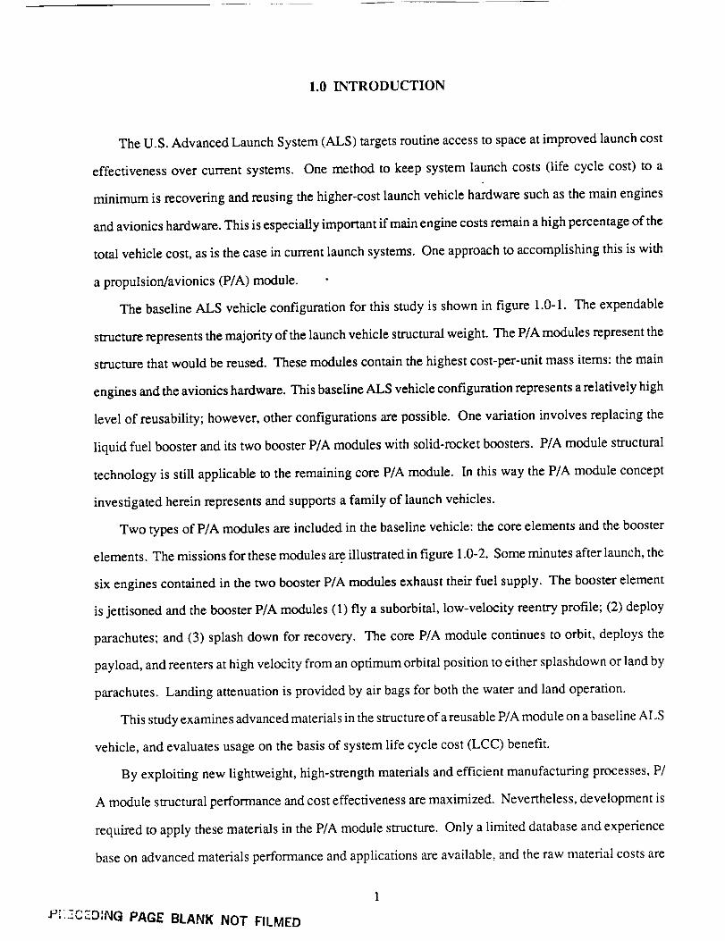
The U.S. Advanced Launch System (ALS) targets routine access to space at improved launch cost
effectiveness over current systems. One method to keep system launch costs (life cycle cost) to a
minimum is recovering and reusing the higher-cost launch vehicle hardware such as the main engines
and avionics hardware. This is especially important if main engine costs remain a high percentage of the
total vehicle cost, as is the case in current launch systems. One approach to accomplishing this is with
a propulsion/avionics (P/A) module.
The baseline ALS vehicle configuration for this study is shown in figure 1.0-1. The expendable
structure represents the majority of the launch vehicle structural weight. The P/A modules represent the
structure that would be reused. These modules contain the highest cost-per-unit mass items: the main
engines and the avionics hardware. This baseline ALS vehicle configuration represents a relatively high
level of reusability; however, other configurations are possible. One variation involves replacing the
liquid fuel booster and its two booster P/A modules with solid-rocket boosters. P/A module structural
technology is still applicable to the remaining core P/A module. In this way the P/A module concept
investigated herein represents and supports a family of launch vehicles.
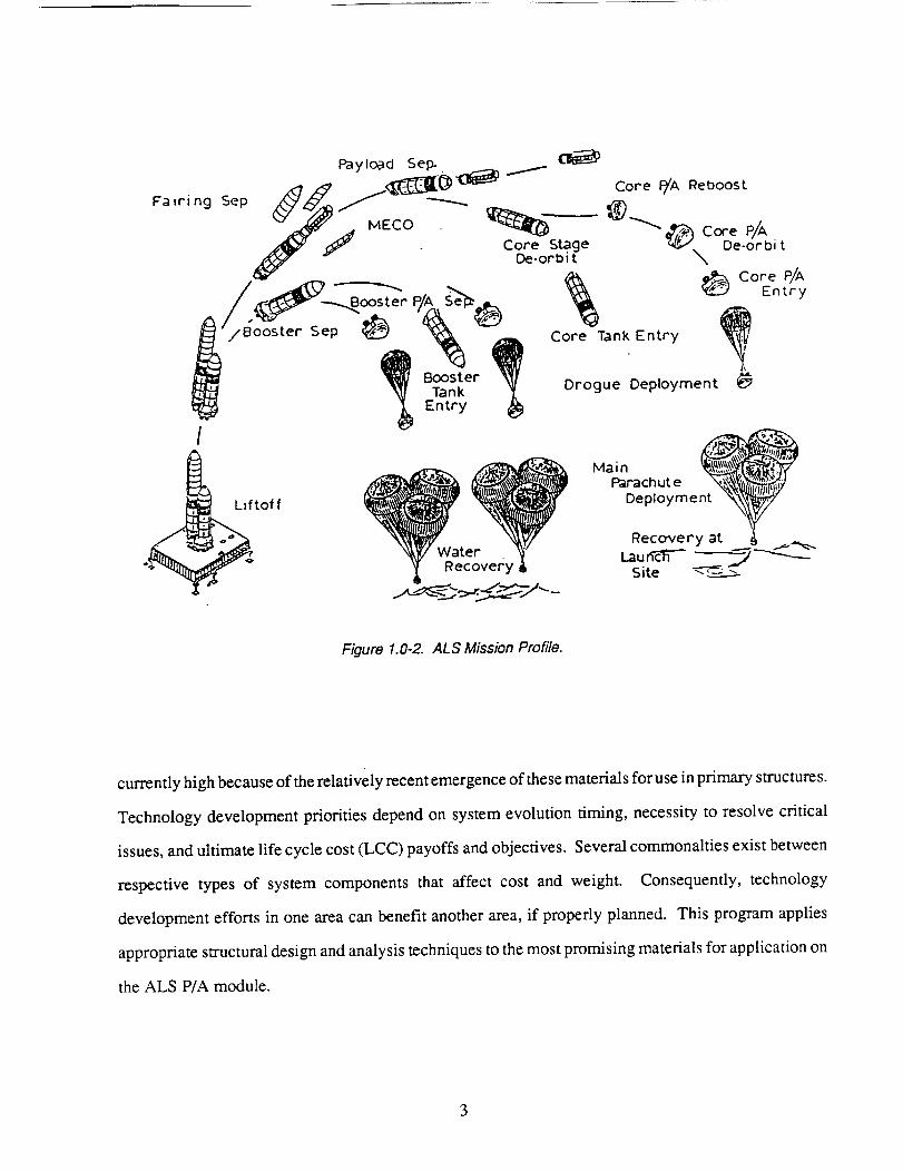
Two types of P/A modules are included in the baseline vehicle: the core elements and the booster
elements. The missions for these modules are illustrated in figure 1.0-2. Some minutes after launch, the
six engines contained in the two booster P/A modules exhaust their fuel supply. The booster element
is jettisoned and the booster P/A modules (1) fly a suborbital, low-velocity reentry profile; (2) deploy
parachutes; and (3) splash down for recovery. The core P/A module continues to orbit, deploys the
payload, and reenters at high velocity from an optimum orbital position to either splashdown or land by
parachutes. Landing attenuation is provided by air bags for both the water and land operation.
This study examines advanced materials in the structure of a reusable P/A module on a baseline ALS
vehicle, and evaluates usage on the basis of system life cycle cost (LCC) benefit.
By exploiting new lightweight, high-strength materials and efficient manufacturing processes, P/
A module structural performance and cost effectiveness are maximized. Nevertheless, development is
required to apply these materials in the P/A module structure. Only a limited database and experience
base on advanced materials performance and applications are available, and the raw material costs are
• r-Tf ,
•P;.-,-,TD_NG PAGE BLANK NOT FILMED
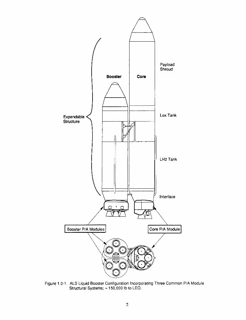
Expendable<_Structure
/
Booster
/2Core
PayloadShroud
Lox Tank
LH2 Tank
Interface
Figure 1.0-1.
P/A Modules Core P/A Module
yALS Liquid Booster Configuration Incorporating Three Common P/A ModuleStructural Systems; = 150,000 Ib to LEO.
Payload Sep.
in S ,<7_ j{_31[(_ "_ _ CoreP/AReboost
/ _ _ __ _ _ Core?/_
/ P _ '_ Core Tank Entry ,
_ Tank _, Drogue Deployment
t_ _ Entryl
' Deployment
Recovery at
Recovery Lau_ __Site ---
Figure 1.0-2. ALS Mission Profile.
currently high because of the relatively recent emergence of these materials for use in primary structures.
Technology development priorities depend on system evolution timing, necessity to resolve critical
issues, and ultimate life cycle cost (LCC) payoffs and objectives. Several commonalties exist between
respective types of system components that affect cost and weight. Consequently, technology
development efforts in one area can benefit another area, if properly planned. This program applies
appropriate structural design and analysis techniques to the most promising materials for application on
the ALS P/A module.
3

This page intentionally left blank
4
2.0 OBJECTIVES
The objective of this program is to identify and demonstrate the potential of advanced materials and
processes, internal insulation, and thermal protection systems for cost-effective, reusable structures for
an ALS reusable element such as the P/A module. The major premise of the P/A module is that the main
engines and avionics computers are valuable enough that reusing them reduces overall launch system
costs. The specific objective for Phase I is a structural concept design and analysis study on a selected
ALS recoverable P/A module system. Whenever possible, system definition for this study relied on a
systems study performed under contract to NASA Marshall Space Flight Center (ref. 1). The primary
output of Phase I is a technology development plan to guide technology validation and demonstration
in Phases II and III.
5

Thispageintentionallyleft blank
3.0 PROGRAM PLAN
The overall program is divided into three phases: Phase I: System Design Study, Phase II:
Technology Validation, and Phase III: Hardware Demonstration.
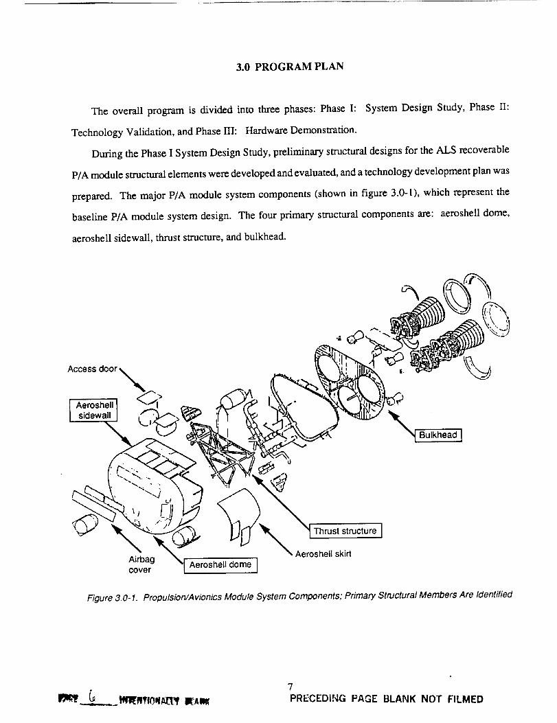
During the Phase I System Design Study, preliminary structural designs for the ALS recoverable
P/A module structural elements were developed and evaluated, and a technology development plan was
prepared. The major P/A module system components (shown in figure 3.0-1), which represent the
baseline P/A module system design. The four primary structural components are: aeroshell dome,
aeroshell sidewall, thrust structure, and bulkhead.
Access door
Aeroshel, I _1 _
sidewa I
_ Bulkhead I
%
'_ _ Thrust structure J_, Aeroshell skirt
Airbag "[ Aeroshell dome Jcover
Figure 3.0-1. Propulsion�Avionics Module System Components; Primary Structural Members Are Identified
7
PRECEDING PAGE BLANK NOT FILMED
Three major tasks were performed in the first phase. These are:
Task 1. Concept Development: (1) defined a candidate structural system; (2) identified system and
structural requirements that guide structural concept definition; and (3) identified a policy for ensuring
the design concepts are compatible with system recovery.
Task 2. Content Definition and Evaluation: (1) prepared a variety of design concept options
for the key structural components; (2) evaluated those concepts for structural efficiency and
manufacturability; (3) conducted LCC analysis of the structural concepts; and (4) identified the most
promising structural concepts for planning the technology validation and hardware demonstration tasks
in phases II and III.
Task 3. Technology Develooment Plan: (1) prepared technology development plans leading to
technology validation and hardware demonstration during phases II and III, respectively; (2) identified
and prioritized materials, processes, and manufacturing for further development that would enhance
reusable structural design and provide significant cost benefits; (3) prepared cost estimates and
schedules for phase II and III implementation, which include the required structural and material
allowable data, manufacturing development tasks, structural element tests, and demonstration tests.
4.0 TECHNICAL DISCUSSION
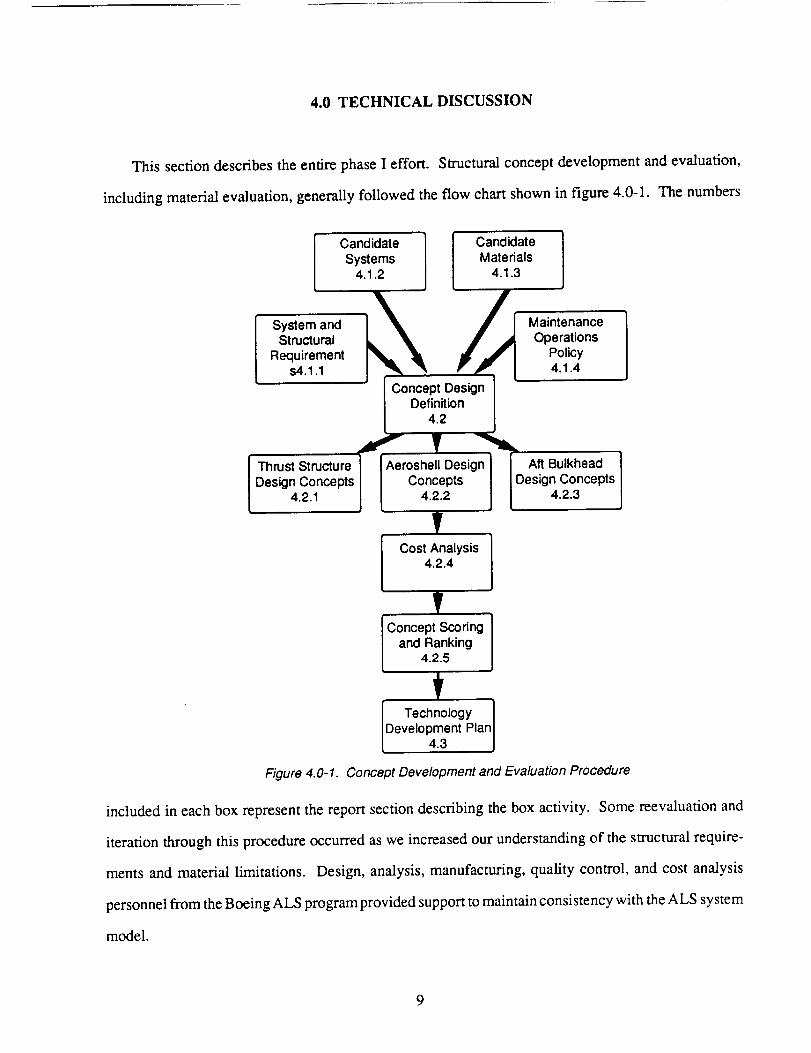
This section describes the entire phase I effort. Structural concept development and evaluation,
including material evaluation, generally followed the flow chart shown in figure 4.0-1. The numbers
CandidateSystems
4.1.2
CandidateMaterials
4.1.3
System andStructural
Requirements4.1.1
MaintenanceOperations
Policy4.1.4
Thrust StructureDesign Concepts
4.2.1
Aeroshell DesignConcepts
4.2.2
nt mCost Analysis
4.2.4
il&,,
Aft BulkheadDesign Concepts
4.2.3
Concept Scoringand Ranking
4.2.5
fTechnology ]
Develo P4m3nt Plan I
Figure 4.0-I. Concept Development and Evaluation Procedure
included in each box represent the report section describing the box activity. Some reevaluation and
iteration through this procedure occurred as we increased our understanding of the structural require-
ments and material limitations. Design, analysis, manufacturing, quality control, and cost analysis
personnel from the Boeing ALS program provided support to maintain consistency with the ALS system
model.
4.1 TASK 1- CONCEPT DEVELOPMENT
ALS cost and operability goals suggest the benefits in using structure common for both the core and
the booster P/A module vehicles. Common structure reduces the cost of engineering development,
tooling, inventories, and speeds progress down the manufacturing learning curve. Our structural
concepts have been developed to accommodate both P/A module vehicles, i.e., a common P/A module.
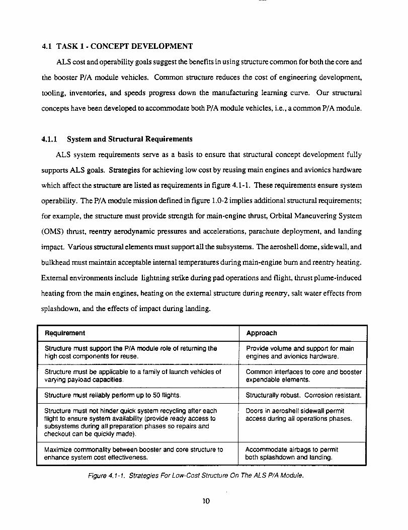
4.1.1 System and Structural Requirements
ALS system requirements serve as a basis to ensure that structural concept development fully
supports ALS goals. Strategies for achieving low cost by reusing main engines and avionics hardware
which affect the structure arc listed as requirements in figure 4.1-1. These requirements ensure system
operability. The P/A module mission defined in figure 1.0-2 implies additional structural requirements;
for example, the structure must provide strength for main-engine thrust, Orbital Maneuvering System
(OMS) thrust, reentry aerodynamic pressures and accelerations, parachute deployment, and landing
impact. Various structural elements must support all the subsystems. The aeroshell dome, sidewall, and
bulkhead must maintain acceptable internal temperatures during main-engine burn and reentry heating.
External environments include lightning strike during pad operations and flight, thrust plume-induced
heating from the main engines, heating on the external structure during reentry, salt water effects from
splashdown, and the effects of impact during landing.
Requirement Approach
Structure must support the P/A module role of returning the Provide volume and support for mainhigh cost components for reuse, engines and avionics hardware.
Structure must be applicable to a family of launch vehicles of Common interfaces to core and boostervarying payload capacities, expendable elements.
Structure must reliably perform up to 50 flights. Structurally robust. Corrosion resistant.
Structure must not hinder quick system recycling after eachflight to ensure system availability (provide ready access tosubsystems during all preparation phases so repairs andcheckout can be quickly made).
Maximize commonality between booster and core structuretoenhance system cost effectiveness.
Doors in aeroshell sidewall permitaccess during all operations phases.
Accommodate airbags to permitboth splashdown and landing.
Figure 4.1-1. Strategies For Low-Cost Structure On The ALS P/A Module.
10
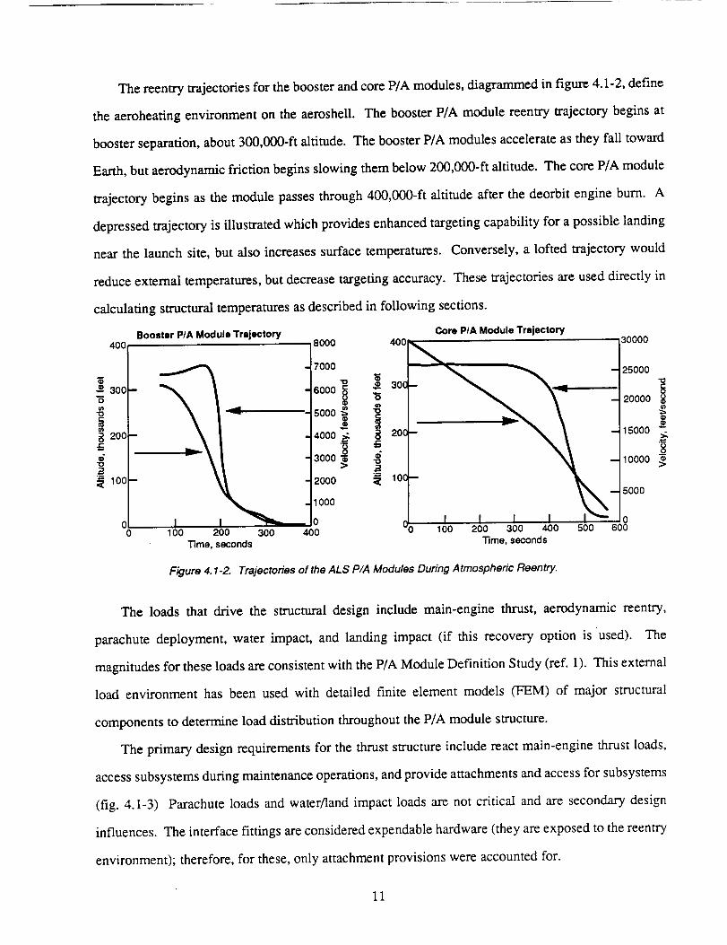
The reentry trajectories for the booster and core P/A modules, diagrammed in figure 4.1-2, define
the aeroheating environment on the aeroshell. The booster P/A module reentry trajectory begins at
booster separation, about 300,000-ft altitude. The booster P/A modules accelerate as they fall toward
Earth, but aerodynamic friction begins slowing them below 200,000-ft altitude. The core P/A module
trajectory begins as the module passes through 400,000-ft altitude after the deorbit engine burn. A
depressed trajectory is illustrated which provides enhanced targeting capability for a possible landing
near the launch site, but also increases surface temperatures. Conversely, a lofted trajectory would
reduce external temperatures, but decrease targeting accuracy. These trajectories are used directly in
calculating structural temperatures as described in following sections.
Booster P/A Module Trajectory400 5000 400
-= 30O
200
100 m
00
7000
_ 300
6000 _
5000 _
4ooo.=_ _ 2oc3000 _
> _2000 _ 10C
-1000
I o100 200 300 400
_me, seconds
Core PIA Module Trajectory30000
25000
20000
15000 "_'
10000
5000
I100 200 300 400 500 600
_me, seconds
Figure 4.1-2. Trajectories of the ALS P/A Modules During Atmospheric Reentry.
The loads that drive the structural design include main-engine thrust, aerodynamic reentry,
parachute deployment, water impact, and landing impact (if this recovery option is used). The
magnitudes for these loads are consistent with the P/A Module Definition Study (ref. 1). This external
load environment has been used with detailed finite element models (FEM) of major structural
components to determine load distribution throughout the P/A module structure.
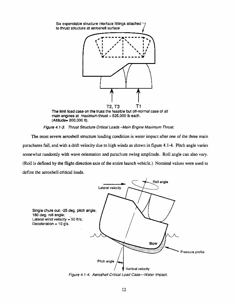
The primary design requirements for the thrust structure include react main-engine thrust loads,
access subsystems during maintenance operations, and provide attachments and access for subsystems
(fig. 4.1-3) Parachute loads and water/land impact loads are not critical and are secondary design
influences. The interface fittings are considered expendable hardware (they are exposed to the reentry
environment); therefore, for these, only attachment provisions were accounted for.
11
Six expendable structure interface fittingsattached -7to thrust structure at aeroshell surface /
l t I s I N I # || -tl s S I ", IS- i_tl s I _ ii I
*..... "..... I
T2, T3 T1The limit load case on the truss the feasible but off-normal case of allmain engines at maximum thrust = 525,000 Ib each.(Altitude= 200,000 ft).
Figure 4.1-3. Thrust Structure Critical Loads -Main Engine Maximum Thrust.
The most severe aeroshell structure loading condition is water impact after one of the three main
parachutes fail, and with a drift velocity due to high winds as shown in figure 4.1-4. Pitch angle varies
somewhat randomly with wave orientation and parachute swing amplitude. Roll angle can also vary.
(Roll is def'med by the flight direction axis of the entire launch vehicle.) Nominal values were used to
define the aeroshell critical loads.
qoll angle=,..._
Lateral velocity
Single chute out; -25 deg. pitch angle;180 deg. roll angle;Lateral wind velocity = 50 ff/s;Deceleration = 10 g's.
Bow
_ Pressure profile
Figure 4. 1-4.
Pitch angle
Vertical velocity
Aeroshell Critical Load Case--Water Impact.
12
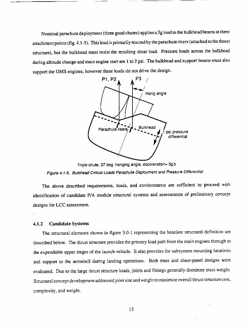
Nominal parachute deployment (three good chutes) applies a 3g load to the bulkhead beams at three
attachment points (fig. 4.1-5). This load is primarily reacted by the parachute risers (attached to the thrust
structure), but the bulkhead must resist the resulting shear load. Pressure loads across the bulkhead
during altitude change and main engine start are 1 to 3 psi. The bulkhead and support beams must also
support the OMS engines, however these loads do not drive the design.
P1,Pa P3 /
_=lle/ _ i'.7-..: u, ea0-"7I Parachute-r sers, ! '- __" ....... • !
/ _ " _,,, J,1 psi pressure
_ differential
Triple chute, 37 deg. hanging angle, deceleration= 3g's
Figure 4.1-5. Bulkhead Critical Loads Parachute Deployment and Pressure Differential
The above described requirements, loads, and environments are sufficient to proceed with
identification of candidate P/A module structural systems and assessments of preliminary concept
designs for LCC assessment.
4.1.2 Candidate Systems
The structural elements shown in figure 3.0-1 representing the baseline structural definition are
described below. The thrust structure provides the primary load path from the main engines through to
the expendable upper stages of the launch vehicle. It also provides for subsystem mounting locations
and support to the aeroshell during landing operations. Both truss and shear-panel designs were
evaluated. Due to the large thrust structure loads, joints and fittings generally dominate truss weight.
Structural concept development addressed joint size and weight to minimize overall thrust structure cost,
complexity, and weight.
13
The aeroshell dome takes the primary reentry heating and the landing loads on both the core and
booster P/A modules. The aeroshell dome contains covers for the airbag landing attenuation system.
The dome shape accommodates a volume for landing bag stowage, and accommodates access and
propellant line doors. The sidewall provides an aerodynamic surface during reentry and protects interior
components from heat. Access doors are required in the sidewall for subsystem access during launch
preparation. Additional doors may be required for a flotation collar system. A combined dome and
sidewall structure has been considered and may be integrated or may be separately joined elements
depending on the fabrication approach.
The bulkhead protects internal subsystems from the plume heating environment and supports
external subsystems such as orbital maneuvering system engines and parachutes. This structure is
initially defined as a stiffened panel with additional beams for the point loads. The structure must be
either thermally resistant or insulated from the plume heating environment.
4.1.3 Candidate Materials and Materials Selection
The high performance usually required of launch vehicle structure leads to materials balancing
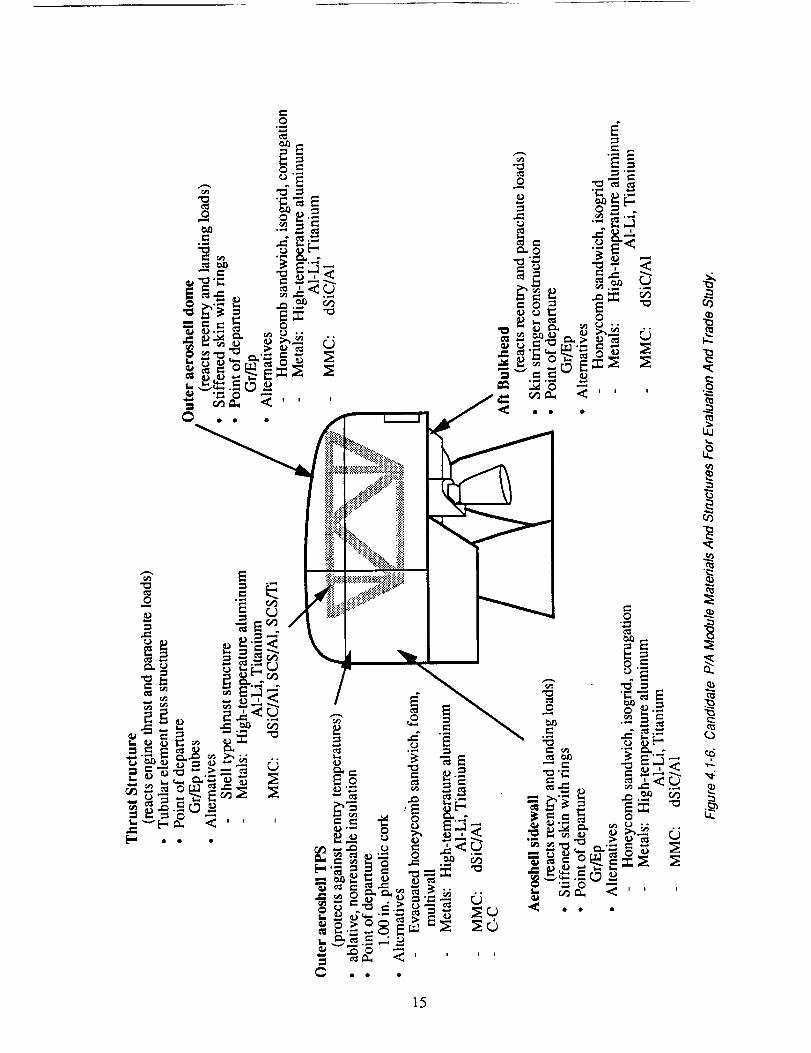
structural efficiency with reasonable fabrication cost. Candidate material types as they apply to the
identified structural elements are listed in figure 4.1-6. A detailed mechanical and physical property
database across appropriate operating temperatures was compiled and is included in Appendix A.
Graphite/epoxy (Gr/Ep) was specified by the ALS reference P/A module configuration (ref. 1). Specific
material formulations, alloys, and heat treatments are selected to the level the design detail requires.
During full-scale development, material specifications would be selected including strengthening
treatments, precise fiber and matrix, and reinforcement fractions.
Because the main engines produce high loads in the thrust structure, candidate materials should have
high specific compressive strength and stiffness. Since it is in a moderate thermal environment, high-
temperature strength is not a benefit to thrust structure materials. If the access requirements are reduced
and shear web structure is feasible, materials with high specific shear stiffness and strength are beneficial
to reducing weight.
14
"0
0
c_c_
ell
\
15
The aerosheU dome is subject to high bending and compression loads from splashdown, therefore
a highly stiffened shell structure is beneficial. Materials should have high specific stiffness and moderate
temperature capability. The aeroshell sidewall experiences less severe loading and temperatures,
therefore lower cost materials and structures may be viable there.
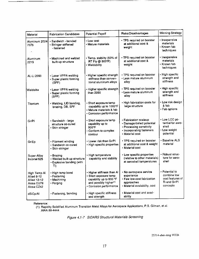
A qualitative assessment of candidate materials for application on the aeroshell and bulkhead
structure is displayed in figure 4.1-7. Typical aerospace fabrication methods are listed for 2024, 7075,
and 2219 aluminums to cover the low-cost and low-risk spectrum of concepts. In this context, risk is
proportional to the cost of fully developing a concept for flight hardware. Aluminum-lithium (A1-Li)
is included as a less developed but potentially higher performance material. A common drawback of
these materials is the requirement of applying a thermal protection system (TPS) to the external surface
to survive the reentry environment for the aeroshell and the main engine plume heating environment for
the bulkhead. A list of candidate TPS materials with quantitative and qualitative attributes is included
in Appendix A.
Titanium can potentially perform under the heating environment indicated by preliminary thermal
analysis, and is considered a robust material, which is an important attribute for reusable structure with
a mission profile that includes launch and recovery. Graphite/polyimide (Gr/PI) composite materials are
resistant to the temperatures indicated by the preliminary thermal analyses for the booster P/A module,
and can be laid up and cured in the desired aeroshell dome compound curvature. Potentially, large
structural members are feasible, thereby requiring few structural splices, although process and structural
development would be needed. Graphite/epoxy was specified by the Boeing ALS program as the
baseline material for the aeroshell and bulkhead, and can also be laid up in the required complex contours.
The Inconel alloys are robust, have greater high-temperature resistance than Ti, and can be fabricated
in similar ways to Ti, but have comparatively low specific properties. The high-temperature aluminum
(HTA) alloys have potential in hot area applications, but are relatively undeveloped, as are the
discontinuous silicon carbide-reinforced aluminum (dSiC/A1) MMCs. Silicon carbide-fiber-reinforced
metals (titanium or aluminum) were considered only for the thrust structure tubes due to their high
compressive strength and stiffness and limited level of development for large sheets.
16
Material Fabrication Candidates Potential Payoff Risks/Disadvantages Winning Strategy
Aluminum 20247075
Aluminum
2219
AL-Li 2O9O
Weldalite
Titanium
Gr/PI
Gr/Ep
Super-AlloyInconel 625
High Tamp AIAllied 8-12
Allied 12-12Alcoa CU78
Alcoa CZ42
dSiCp/AI
• Sandwich - bonded
• Stringer stiffened- fastened
• Machined and welded
built-up structure
• Laser VPPA welding
• Super plastic forming
(SPF)
• Laser VPPA welding• Super plastic forming
(SPF)
• Welding, LID bonding,
brazing, DB, SPF
• Sandwich - largestructure co-cured
• Skin stringer
• Filament winding• Sandwich co-cured
• Skin-stringer
• Brazing
• Welded built-up structure• Explosive bonding (with
Ti)
• High tamp bond
• Fastening• Machining
• Forging
• Fastening, bonding
• Low cost• Mature materials
• Temp. stability (50% of
RT Fty @ 500°F)• Weldability
• Higher specific strengthstiffness than conven-
tional aluminum alloys
• Higher specific strengththan 2090
• Short exposure tampcapability up to 1000°F
• Mature materials & lab
• Corrosion performance
• Short exposure tampcapability up to900oF
• Conform to complexcontour
• Lower risk than Gr/PI
• High specific properties
• High temperature
capability and stability
• Higher stiffness than AI
• Short exposure tampcapability up to 800 °Fand possibly higher <_)
• Corrosion performance
• High specific stiffnessand strength
• TPS required on boosterat additional cost &
weight
• TPS required on boosterat additional cost &
weight
• TPS required on booster• Less mature aluminum
alloy
• TPS required on booster• Less mature aluminum
alloy
• High fabrication costs forlarge structure
• Fabrication scaleup• Damage/defect potential
• Processing sensitivity
• Incorporating fasteners• Material cost
• TPS required on booster
at additional cost & weight• Material cost
• Low specific properties
(relative to other materials)at aeroshell temperatures
• No aerospace service
experience• Few low-cost fabrication
approaches• Material availability, cost
• Material cost and avail-
ability
• Inexpensivematerials
• Known lab
techniques
• Inexpensivematerials
• Known lab
techniques
• High specificstrength andstiffness
• High specific
strength andstiffness
• Low risk design& lab
• Fab options
• Low LCC po-tential for aero-
shell
• Low weightpotential
• Baseline ALS
material
• Robust struc-ture for aero-
shell
• Potential tocombine low
cost features ofTi and Gr/PI
concepts
Reference:
(1) Rapidity Solidified Aluminum Transition Metal Alloys for Aerospace Applications, P S Gilman, etalAIAA 88-4444
Figure 4 1-7 SIDARS Structural Materials Screening
25314abmmngg0326
17
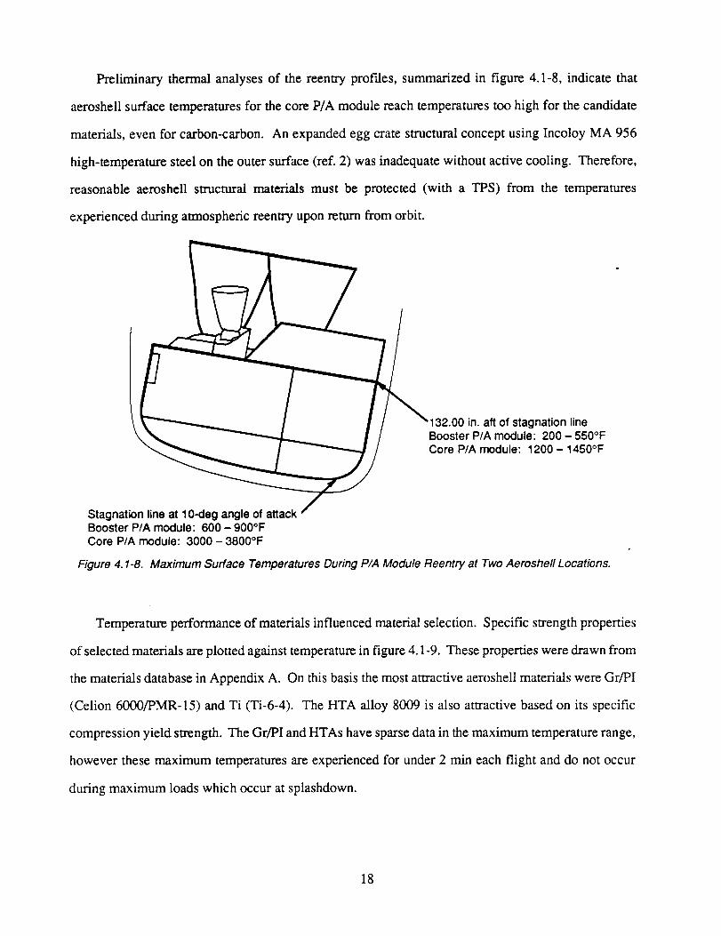
Preliminary thermal analyses of the reentry prof'des, summarized in figure 4.1-8, indicate that
aeroshell surface temperatures for the core P/A module reach temperatures too high for the candidate
materials, even for carbon-carbon. An expanded egg crate structural concept using Incoloy MA 956
high-temperature steel on the outer surface (ref. 2) was inadequate without active cooling. Therefore,
reasonable aeroshell structural materials must be protected (with a TPS) from the temperatures
experienced during atmospheric reentry upon return from orbit.
132.00 in. aft of stagnation lineBooster P/A module: 200 - 550°FCore P/A module: 1200 - 1450°F
Stagnation line at 10-deg angle of attackBooster P/A module: 600 - 900°FCore P/A module: 3000 - 3800°F
Figure 4.1-8. Maximum Surface Temperatures During P/A Modu/e Reentry at Two Aeroshe/I Locations.
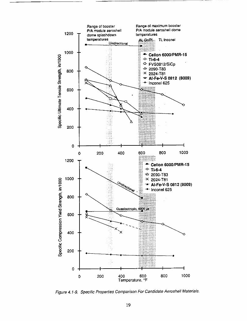
Temperature performance of materials influenced material selection. Specific strength properties
of selected materials are plotted against temperature in figure 4.1-9. These properties were drawn from
the materials database in Appendix A. On this basis the most attractive aeroshell materials were Gr/PI
(Celion 6000/PMR-15) and Ti (Ti-6-4). The HTA alloy 8009 is also attractive based on its specific
compression yield strength. The Gr/PI and HTAs have sparse data in the maximum temperature range,
however these maximum temperatures are experienced for under 2 min each flight and do not occur
during maximum loads which occur at splashdown.
18
1200
1000O
O
,i
•"_ 800C
'_ 600C
E400
¢n 200
1200
o 100000
=-800
600
400E0
200
Figure 4. I-9.
0
Range of booster Range of maximum boosterP/A moduleaeroshell P/A module aeroshelldomedome splashdown temperaturestemperatures _A!_:_r_|_:_:_:Ti, Inconel
-_ Unidirectional ......._:i...................................... _=iiiiiliiiii:_iii!iii!iii!ii!!iill
_ =- Celion 60001PMR-15_:!:i:
ii_ii"<>"TI-6-4=!_i_iG- FVSO812/SiCpi_ii-_- 2090-T83i_i-x 2024-T81
_ _i_i_i-*" AI-Fe-V-S 0812 (8009)
_ i!ii!!!ii!i!i!iiiiiiiiiiiiiiiiiiiii!i!iii_
200 400 600 800 1000
i!::::i::::::::::-,,- Celion 6000/PMR-15
::::::::::::::::::::::::::::::::::::::::::::ii_i_iiiiiiili_ii!_!_i!!iiiili:ili:i_iiiiiii
illiiii!iiiiiiiiiiiiiiil;iliiiiii!i_i!_i_i!!iiiililili_i_ii:
======================:+:+:+:;.:.:
I I .......t..................................
2OO 400 600Temperature,°F
I I
800 1000
Specific Properties Comparison For Candidate Aeroshell Materials.
19
The above review demonstrates that a good range of candidate materials applicable to the P/A
module environment are available for structural concept development. Precise specification of alloy heat
treatments and reinforcement material identification await full-scale development when all system
issues can be thoroughly considered.
4.1.4 Maintenance Operations Policy
A low-cost, routine launch system requires structure that is maintainable, reliable, and operable as
described in figure 4.1-1. Our designs reflect this policy. For instance, the aeroshell contains three large
doors for launch pad access to the internal subsystems, such as avionics computers. In other cases direct
adherence to these requirements is difficult because design concepts and procedures are not well enough
developed. Other system details and procedures enhancing operability may not be well defined and
therefore cannot be incorporated into structural concept definition.
Because the thrust structure is completely encapsulated within the P/A module, inspection between
flights is difficult at best without disassembly. Consequently, our design approach emphasizes a robust
structure.
The most extensive of maintenance operations involves the TPS. Upon reentry from orbit, the core
P/A module flight profile is depressed for targeting accuracy increasing temperatures on the aeroshell
surface. The extremely high temperatures near the stagnation point (fig. 4.1-8) drives the configuration
toward an ablative layer in that region. This ablator must be replaced often and perhaps for each mission.
Conversely, for the booster P/A module, system operability is enhanced by eliminating the TPS because
temperatures are less and can be resisted by high-temperature materials.
20
4.2 TASK 2: CONCEPT DEFINITION AND EVALUATION
A muhidiscipline product development team (PDT) approach was used so that involved personnel
would be cooperatively familiar with details of the design prior to conducting analyses (e.g., structural,
manufacturing, QA, cost). Concepts were then effectively defined to the extent required for equivalent
structural, manufacturing, and cost analysis. Appendix B contains summaries of all structural concepts
defined and discussed in the PDT. The leading concepts, based on qualitative assessment by the PDT,
were provided with additional design and analysis definition.
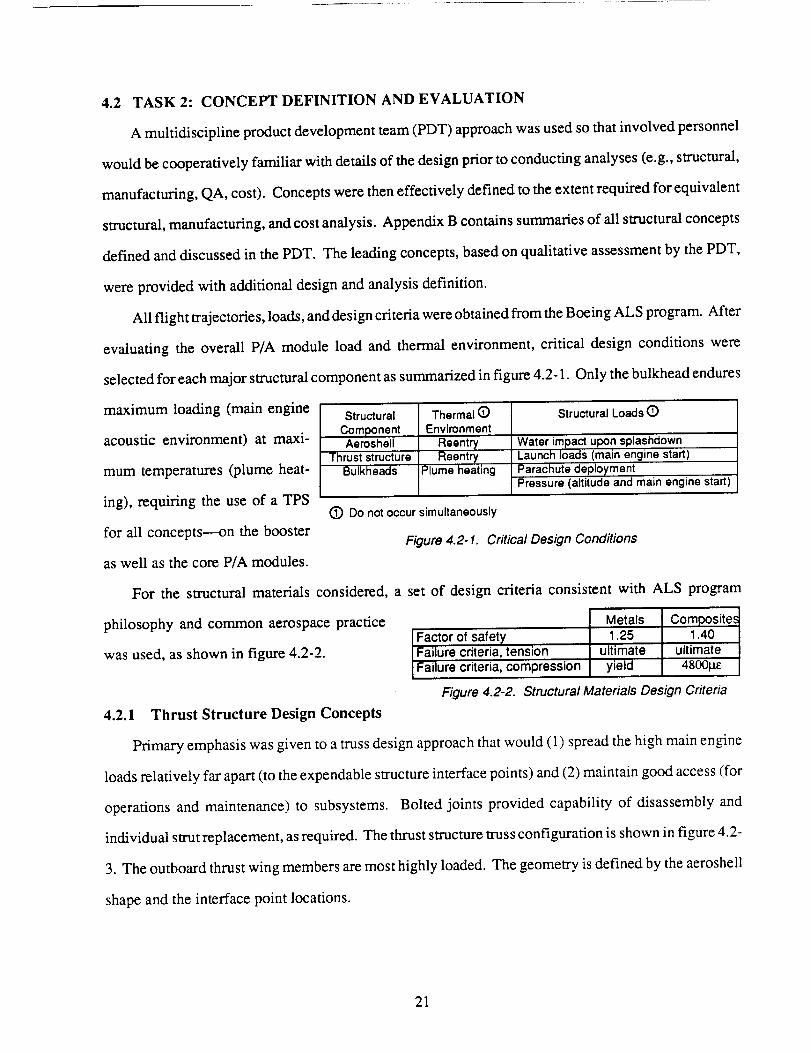
All flight trajectories, loads, and design criteria were obtained from the Boeing ALS program. After
evaluating the overall P/A module load and thermal environment, critical design conditions were
selected for each major structural component as summarized in figure 4.2-1. Only the bulkhead endures
maximum loading (main engine
acoustic environment) at maxi-
mum temperatures (plume heat-
ing), requiring the use of a TPS
for all concepts----on the booster
as well as the core P/A modules.
Structural
ComponentAeroshell
Thrust structureBulkheads
Thermal (_)
Environment
ReentryReentry
Plume heating
Structural Loads Q
Water impact upon splashdownLaunch loads (main engine start)
Parachute deploymentPressure (altitude and main engine start)
(_ Do not occur simultaneously
Figure 4.2-1. Critical Design Conditions
For the structural materials considered, a set of design criteria consistent with ALS program
philosophy and common aerospace practice
was used, as shown in figure 4.2-2.
Metals Composite,.1.40Factor of safety 1.25
Failure criteria, tension ultimate ultimateFailure criteria, compression yield 4800pe
Figure 4.2-2. Structural Materials Design Criteria
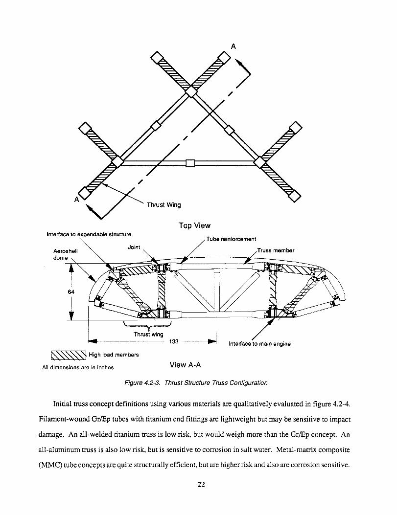
4.2.1 Thrust Structure Design Concepts
Primary emphasis was given to a truss design approach that would (1) spread the high main engine
loads relatively far apart (to the expendable structure interface points) and (2) maintain good access (for
operations and maintenance) to subsystems. Bolted joints provided capability of disassembly and
individual strut replacement, as required. The thrust structure truss configuration is shown in figure 4.2-
3. The outboard thrust wing members are most highly loaded. The geometry is defined by the aeroshell
shape and the interface point locations.
21
A
ThrustWing
Top View
Interfaceto expendable structure
/ Tube reinforcement
Aeroshell_ Joint
dome\I ""
_'-'--'T---")
Thrustwing 13 3Interface to main engine
_X._X__ High load members
All dimensions are in inches View A-A
Figure 4.2-3. Thrust Structure Truss Configuration
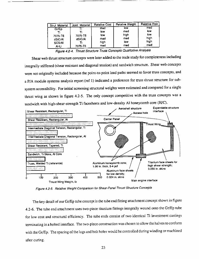
Initial truss concept definitions using various materials are qualitatively evaluated in figure 4.2-4.
Filament-wound Gr/Ep tubes with titanium end fittings are lightweight hut may be sensitive to impact
damage. An all-welded titanium truss is low risk, but would weigh more than the Gr/Ep concept. An
all-aluminum truss is also low risk, but is sensitive to corrosion in salt water. Metal-matrix composite
(MMC) tube concepts are quite structurally efficient, but are higher risk and also are corrosion sensitive.
22
Strut Material Joint Material
Gr/EpTi
7075-T6
dSiC/AISCS/AI
AI-Li
Figure 4.2-4.
TiTi
7075-T6
dSiC/AlTi
7075-'1"6
Relative Cost
reedlow
lowreed
highmed
Relative Weightlow
reed
highreed
low
reed
Relative Riskreed
low
low
highhighreed
Thrust Structure Truss Concepts Quafitative Analysis
Shear web thrust structure concepts were later added to the trade study for completeness including
integrally stiffened (shear resistant and diagonal tension) and sandwich structure. Shear web concepts
were not originally included because the point-to-point load paths seemed to favor truss concepts, and
a P/A module systems analysis report (ref 1) indicated a preference for truss thrust structure for sub-
system accessibility. For initial screening structural weights were estimated and compared for a single
thrust wing as shown in figure 4.2-5. The only concept competitive with the truss concepts was a
sandwich with high-shear-strength Ti facesheets and low-density A1 honeycomb core (H/C).
S ........... .. Aeroshell structure Expendable structurenear _esJs_am, Heaangular, it / interface
:_:__i ::: I _" / Access hole \
i . i i i..#.#/j#/...l¢
' Shea'r Flesi'stant: Rectangular, A| Center Panel / -" "........... ,._
\ _ /" _fhrustWing__ "_
Intermediate Diagonal Tension, Rectangular, Zi t _,___ -_
Intermediate Diagonal Tension, Rectangular, AI
i i i -iii i ':1 i
Shear Resistant , TaPered, Ti I !
Truss, Welded Ti (reference) Aluminum honeycomb core; Titanium face _heets for
.ooi.. t,,=..3-.=f / /J 0 050 in skins
; ..................m Aluminum face hse'ets / 0.050 in. skinsI l l I I for low density; /
0 100 200 300 400 500 0.024 in. skins /
Thrust Wing Weight, Ib Main engine interface
Figure 4.2-5. Re/ative Weight Comparison for Shear-Pane� Thrust Structure Concepts
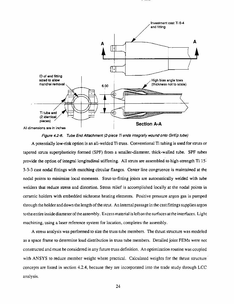
The key detail of our Gr/Ep tube concept is the tube end fitting attachment concept shown in figure
4.2-6. The tube end attachment uses two-piece titanium fittings integrally wound onto the Gr/Ep tube
for low cost and structural efficiency. The tube ends consist of two identical Ti investment castings
terminating in a bolted interface. The two-piece construction was chosen to allow the halves to conform
with the Gr/Ep. The spacing of the lugs and bolt holes would be controlled during winding or machined
after curing.
23
ID of end fittingsized to allow
Investmentcast
//end fitting
Ti6-4
A
High bias angle tows
mandrel removal _. _ ,i _ec_eeb_sn_e_ '.
] Section A-AAll dimensions are in inches J
Figure 4.2-6. Tube End Attachment (2-piece Ti ends integra/ly wound onto Gr/Ep tube)
A potentially low-risk option is an all-welded Ti truss. Conventional Ti tubing is used for struts or
tapered struts superplasticity formed (SPF) from a smaller-diameter, thick-walled tube. SPF tubes
provide the option of integral longitudinal stiffening. All struts are assembled to high-strength Ti 15_
3-3-3 cast nodal fittings with matching circular flanges. Center line congruence is maintained at the
nodal points to minimize local moments. Strut-to-fitting joints are automatically welded with tube
welders that reduce stress and distortion. Stress relief is accomplished locally at the nodal points in
ceramic holders with embedded nichrome heating elements. Positive pressure argon gas is pumped
through the holder and down the length of the strut. An internal passage in the cast fittings supplies argon
to the entire inside diameter of the assembly. Excess material is left on the surfaces at the interfaces. Light
machining, using a laser reference system for location, completes the assembly.
A stress analysis was performed to size the truss tube members. The thrust structure was modeled
as a space frame to determine load distribution in truss tube members. Detailed joint FEMs were not
constructed and must be considered in any future truss definition. An optimization routine was coupled
with ANSYS to reduce member weight where practical. Calculated weights for the thrust structure
concepts are listed in section 4.2.4, because they are incorporated into the trade study through LCC
analysis.
24
Using Gr/Ep, Ti, or SCS/A1 tube members in the baseline truss structure configuration is a feasible
approach to thrust structure design. Time limitations prevented full consideration of shear web thrust
structure, which, in the highly loaded areas, may have cost benefits due to simpler construction.
4.2.2 Aeroshell Design Concepts
A potential LCC reduction stems from using common dome structure for both the core and booster
P/A modules. For a common aeroshell scheme, the core module requires an ablative TPS to resist the
high temperatures encountered during reentry from orbit, while passive approaches are feasible on the
booster P/A module since the temperatures are lower. An aeroshell concept was defined to withstand
the booster trajectory temperatures, but incorporate structural features permitting attachment of an
ablative TPS for flight as a core P/A module aeroshell. This provides a common aeroshell structure
between core and booster modules leading to lower fabrication and maintenance costs.
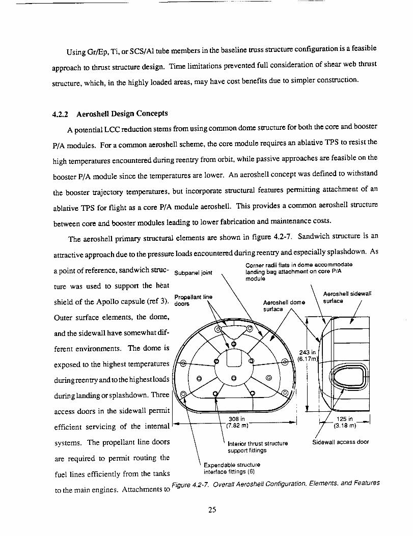
The aeroshell primary structural elements are shown in figure 4.2-7. Sandwich structure is an
a point of reference, sandwich struc- Subpanel joint
ture was used to support the heat
Propellant lineshield of the Apollo capsule (ref 3). doors
Outer surface elements, the dome,
and the sidewall have somewhat dif-
ferent environments. The dome is
exposed to the highest temperatures
during reentry and to the highest loads
during landing or splashdown. Three
access doors in the sidewall permit
efficient servicing of the internal
systems. The propellant line doors
are required to permit routing the
fuel lines efficiently from the tanks
to the main engines.
attractive approach due to the pressure loads encountered during reentry and especially splashdown. As
Corner radii flats in dome accommodate
landing bag attachment on core P/A
module
Aeroshell dome
surface /
\,\
Interior thrust structure
support fittings
24 3 in
(6.17m)
I' !
Aeroshell sidewall
surface /
"-4
" 125 in
=--(3.18 m)_
Sidewall access door
Expendable structureinterface fittings (6)
Attachments to Figure 4.2-Z Overall Aeroshell Configuration, E/ements, and Features
25
the aeroshell dome are designed to prevent water ingress. The interface between the expendable tank
module structure and reusable P/A module occurs at six expendable fittings integral with the P/A module
thrust structure and attach to hard points in the aeroshell. These exposed fittings are degraded during
reentry and are replaced between flights. The thrust structure also is fastened to the aeroshell at eight
interior fittings. There is no penetration of the sandwich in these locations. For non-water landings,
airbags are incorporated between the structural shell and the TPS, which separates after reentry,
eliminating the need for airbag doors in both the shell and TPS. Comer radii fiats in the dome provide
the volume required.
Graohite/Enoxv Aeroshell. The baseline aeroshell concept selected by the ALS project used Gr/
Ep sandwich construction. Fabricating with Gr/Ep is well suited to conforming to the complex shape
of the dome structure, and an experience base exists for building large structural components.
Nevertheless, Gr/Ep cannot endure even the booster module reentry profile, and therefore requires a TPS
on both booster and core modules. A preliminary assumption is that fabricating and replacing TPS
shields contributes significantly to life cycle cost as well as increases system weight.
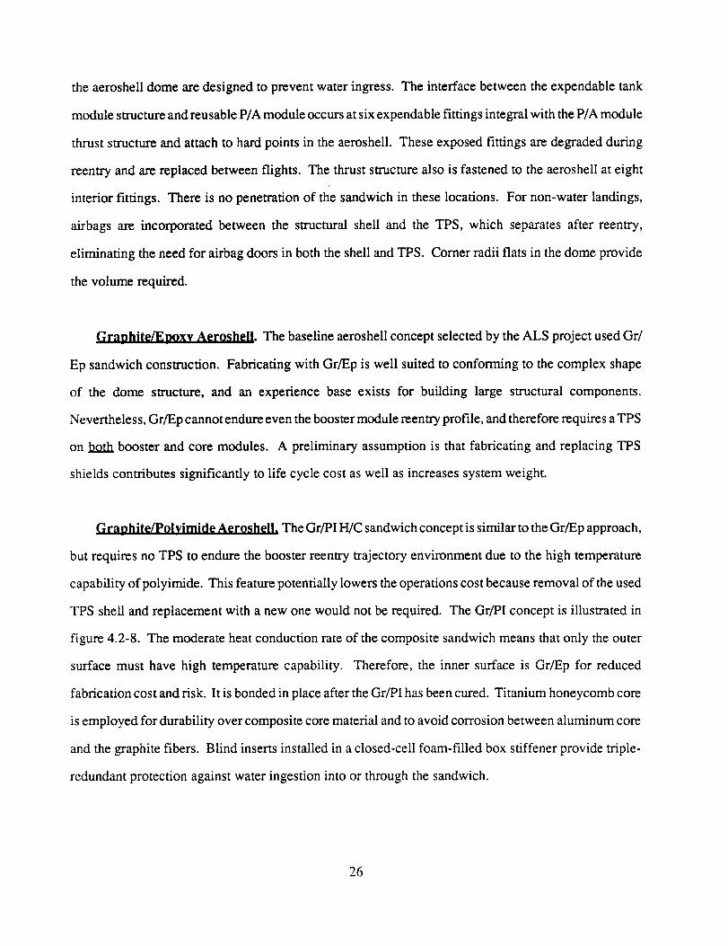
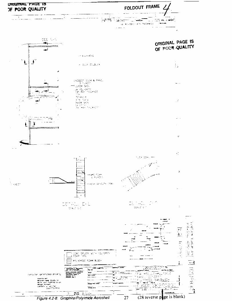
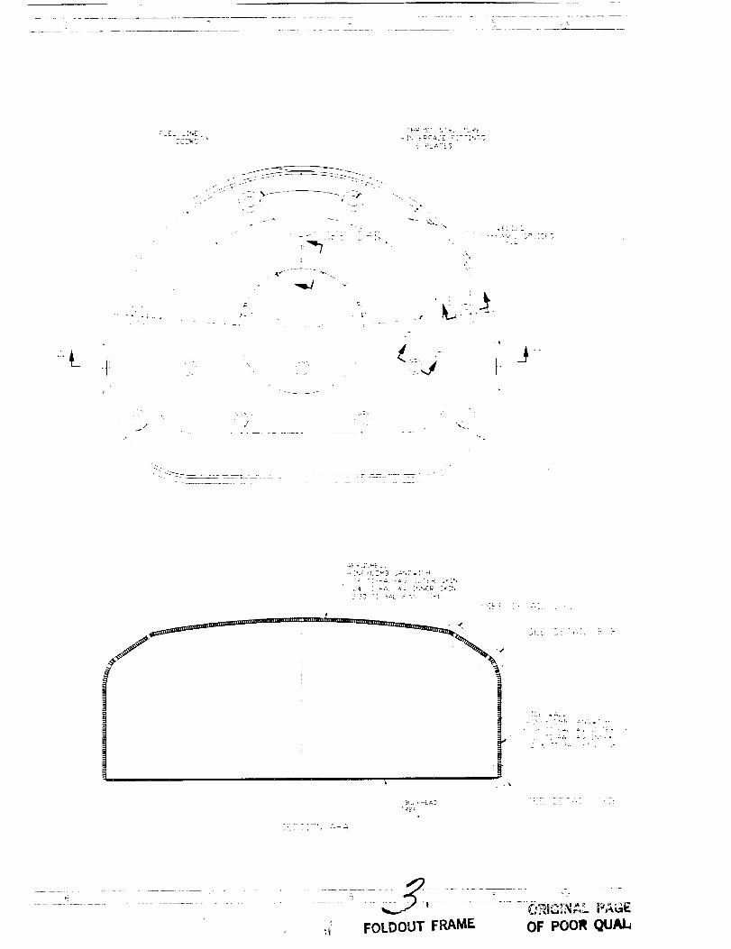
Gr_lnhite/Polvimide Aeroshell. The Gr/PI H/C sandwich concept is similar to the Gr/Ep approach,
but requires no TPS to endure the booster reentry trajectory environment due to the high temperature
capability of polyimide. This feature potentially lowers the operations cost because removal of the used
TPS shell and replacement with a new one would not be required. The Gr/PI concept is illustrated in
figure 4.2-8. The moderate heat conduction rate of the composite sandwich means that only the outer
surface must have high temperature capability. Therefore, the inner surface is Gr/Ep for reduced
fabrication cost and risk. It is bonded in place after the Gr/PI has been cured. Titanium honeycomb core
is employed for durability over composite core material and to avoid corrosion between aluminum core
and the graphite fibers. Blind inserts installed in a closed-cell foam-filled box stiffener provide triple-
redundant protection against water ingestion into or through the sandwich.
26

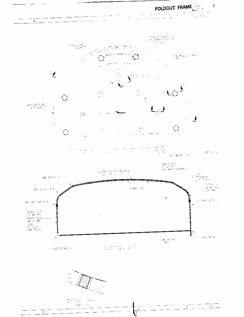
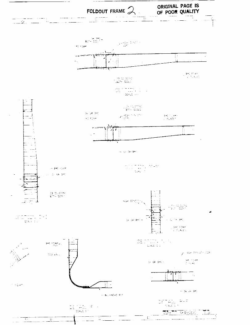
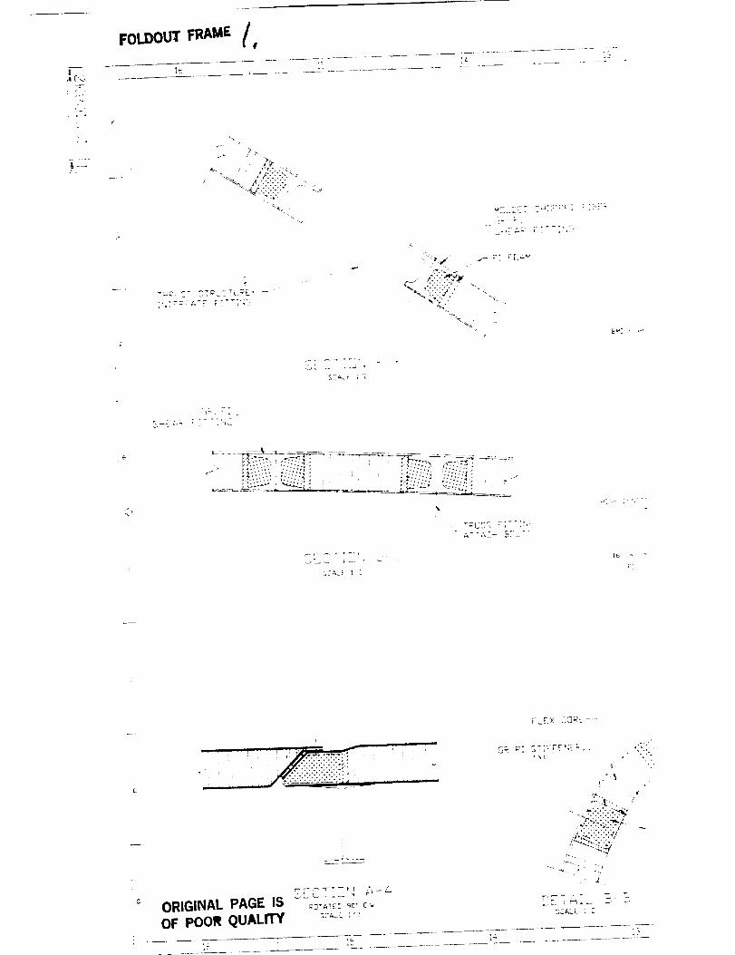
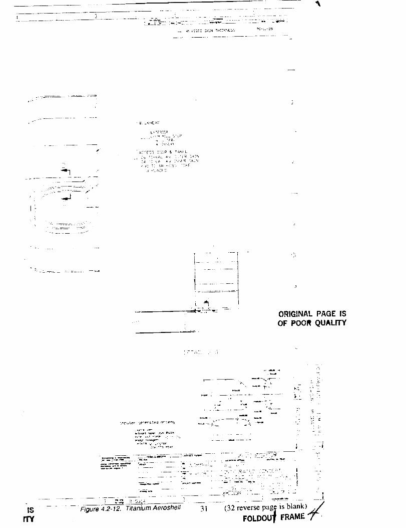
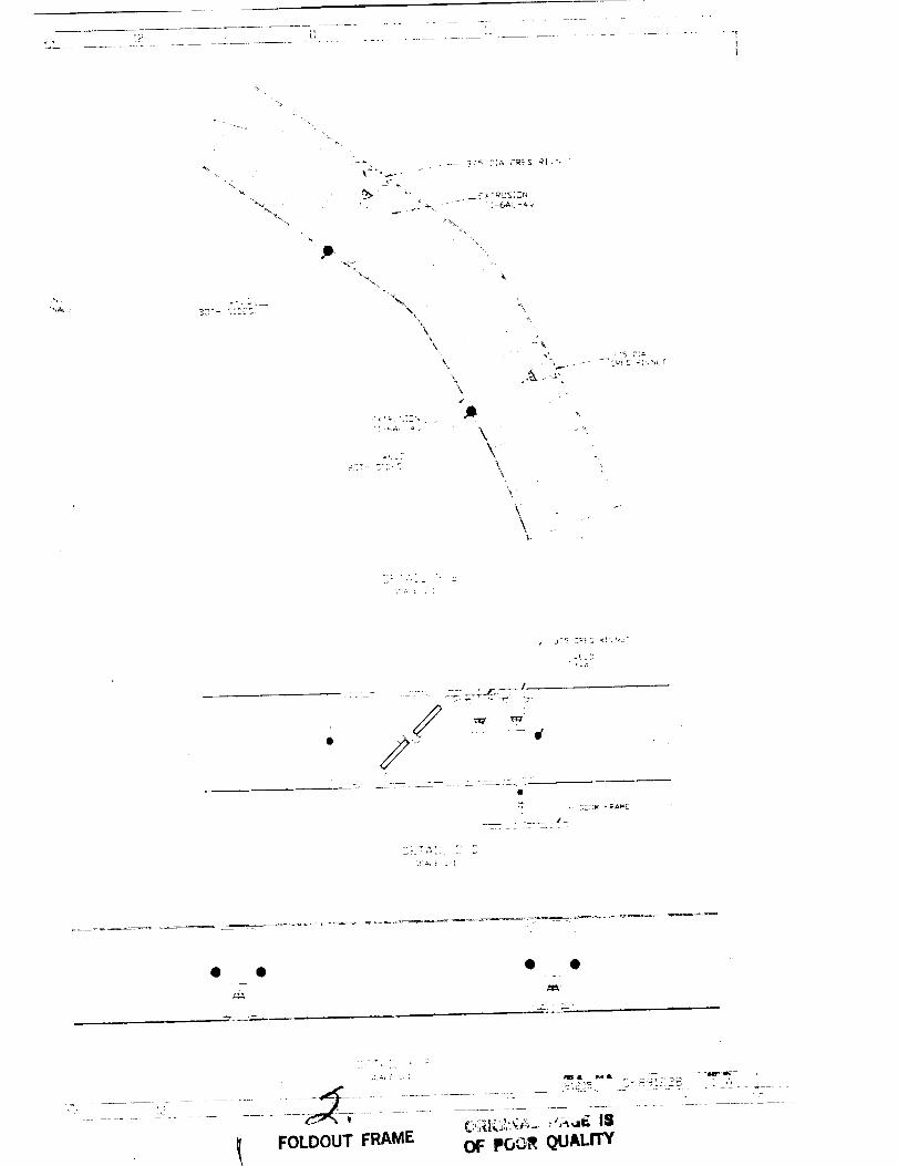
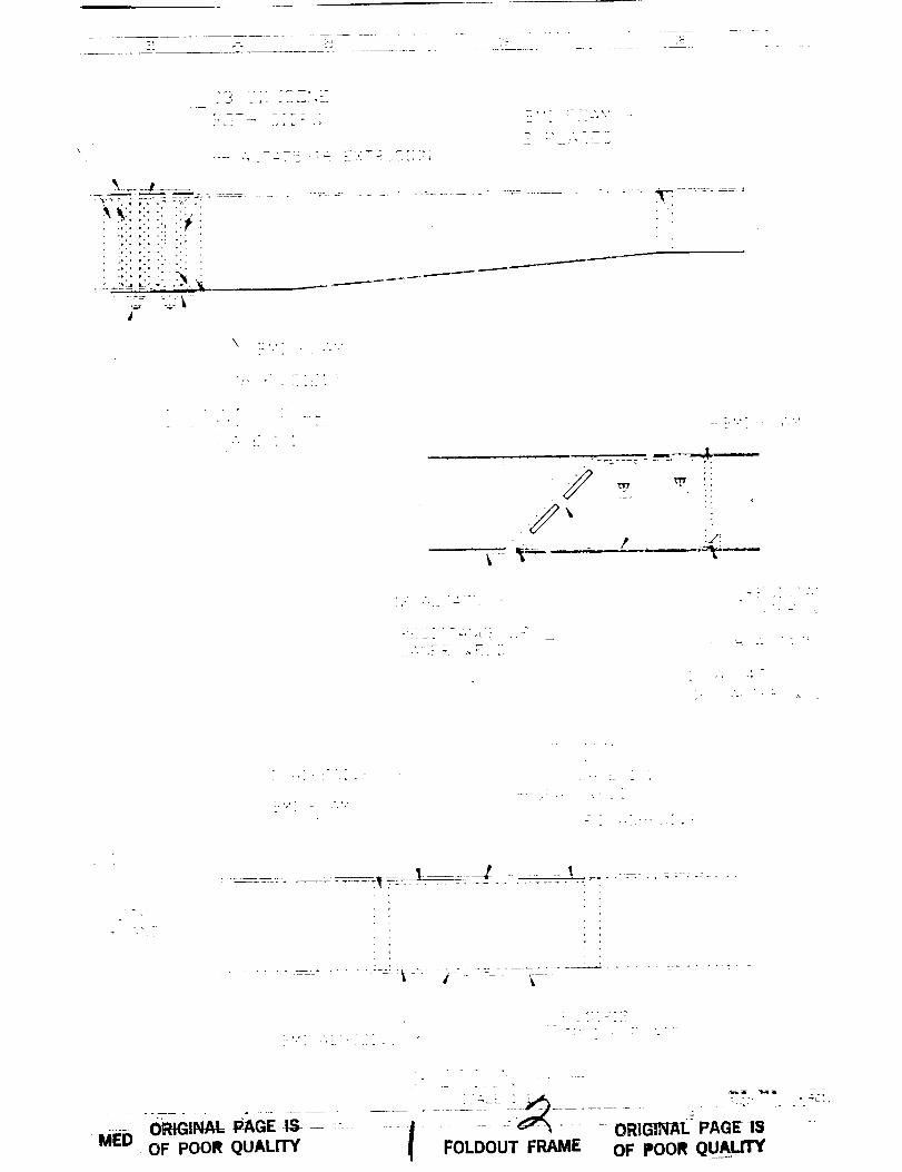
Titanium Aeroshell. The titanium sandwich concept (fig. 4.2-12) features welded frame inserts
with tapped holes at attachment locations for the external airbags. Circular inserts are embedded at the
truss interface attachment locations. The access doors have the same stiffness as the shell and transfer
pressure loads through structural panel fasteners on the outer face sheet. These fasteners are locked
through small Allen-wrench holes in the TPS (see the section on Thermal Protection System below). The
door is sealed with redundant pressurized bulb seals. A door frame limits deflections from splashdown
around the door periphery. Similar seals can be applied to the doors in other aeroshell concepts.
3O
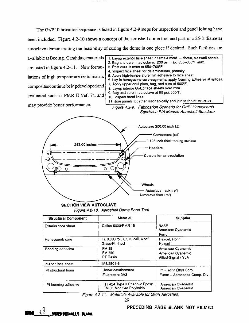
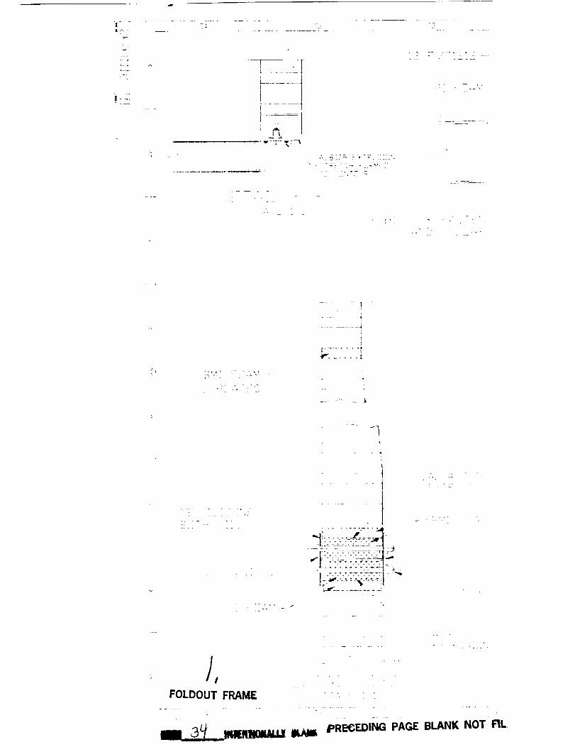
TheGr/PIfabricationsequenceis listedin figure4.2-9stepsfor inspectionandpaneljoining have
beenincluded. Figure4.2-10showsaconceptof theaeroshelldometoolandpart in a25-ft diameter
autoclavedemonstratingthefeasibilityof curingthedomein onepieceif desired.Suchfacilitiesare
availableatBoeing.Candidatematerials
arelistedin figure4.2-11. Newformu-
lationsof hightemperatureresinmatrix
compositescontinuebeingdevelopedand
evaluatedsuchasPMR-II (ref. 7), and
mayprovidebetterperformance.
I.Layup exteriorface sheet infemale mold -- dome, sidewallpanels.
2. Bag and cure inautoclave: 200 psimax, 550-600°F max.3. Post cure inoven to 650-700°F.
4. Inspectface sheet fordelaminations,porosity.
5. Apply high-temperature filmadhesive to face sheet.
6. Lay inhoneycomb core segments; apply foaming adhesive at splices
7. Apply upper caul plate,bag, and cure at 6000F.
8. Layup interiorGr/Ep face sheets over core.
9. Bag and cure inautoclave at 50 psi,350°F.
I0. Inspectbond lines.
1I.Join panels together mechanically and jointo thruststructure.
Figure 4.2-9. Fabrication Scenerio for Gr/PI Honeycomb
Sandwich P/A Module Aeroshell Structure.
___l_/_.._.Autoclave 300.00 inch I.D.Component (ref)
./ ',_=_ 243.00 inches _ ./,_0.125 inch thick tooling surfaceV/
X X"---wheels/ X "'---_u. tcU,;°:elf/o_ I r;:_> <ref >
SECTION VIEW AUTOCLAVE
Figure 4.2-10. Aeroshe/I Dome Bond Too/
Structural Component Material Supplier
Exterior face sheet Celion 6000/PMR 15 BASF
American Cyanam idFerro
Honeycomb core Ti, 0.003 foil, 0.375 cell, 4 pcf Hexcel, RohrGlass/PI, 4 pcf Hexcel
Bonding adhesive FM 35 American Cyanamid
FM 680 American Cyanamid
PT Resin Allied-Signal / YLA
Interior face sheet IM6/3501-6
PI structural foam Under development Imi-Tech/Ethyl Corp.
Fluorocore 3A3 Furon - Aerospace Comp. Div.
PI foaming adhesive HT 424 Type II Phenolic EpoxyFM 30 Modified Polyimide
Figure 4.2-1 I. Materials Available for Gr/PI Aeroshell.
29
PRECEDING PAGE BLANK NOT
-_7, __llilillilOliNJ.! ll_
American CyanamidAmerican Cyanamid
FILMED
UI'IIUIINPII., l"/-IUl:, I_1
:)F POOR QUALITYFOLDOUT FRAME ¢,
:EE ', '
:.! "'J
E
.ki j..E_t
:: J
E ,,
[
=!
E
;tQSESS 2._:.M I1. pA',,,£_
22_-:
TI'" _,N: _
:h',,2_ S, :4
G;. } _ ", '
2"1 _,_, *,'[2K'4_ : "
o_IGINAL PAGE IS
OF pOOR QUALITY
?
:Z,z_',_J,
S:AL:Z 1, :
' ,, L'-l':"ff'"
g L,:._ ,;: i
_° ......
• _ _'_' --1_ _ _I'-_ _'
,/
t_..
c,r _ ,
(28 reverse p ge is blank)
. : ,_ '-'2:.2:7 -_'u_r=x E
.... Z .....L
Figure 4.2-8. Graphite/Polyimide Aeroshell 27

FOLDOUT FRAME _ll,__ J J
f-,._
. f,
J
j
_'L:TC;- :_, "',
: BH T_:L',,,
SE.: :i _,
" gEE. ,S,:-'_:
SEA' _

FOLDOUT FRAME _ ORIGINAL PAGE IS• OF POOR QtJALITY
1
.... i
..... i
-i!
-- - i
"L -_
- 4
__ 2_-: _ _k.
.Q. 7
: {_,:,_..
,._,-
3; Y'-C
P: FEA_- • L w
• _:7- 7,:_]_+, !, 7
: _'-;,:E <
:.L;._- :
E:LL .,a. :
.'.;:AL E : :
f _!_ "+'{ ', :+ " "L.k_
< iL
-J-7 "L::
_g '"

1,i E'_
FOLDOUT FRAME /_
"i
"L
x ,,.,..+.%% _ -
,%,-L _'-- : :T']'4::
_"C_Z,:_[ Z,<]:':_F:" r,_-F:
]_!E _R ;-:-':X?j
e
:t::i".:: t':.'.'/¢ : ' : ; _ " E.'.:-":; ''.'.".""'_;,
.... _ ;i !
ORIGINAL PAGE ISOF POOR QUALITY
?_-CT _-'' A-_
O_ "P[ ST:;-rF' =_, ;;'."....... ?i
,'T .;L ',, /
r: .... _¢
L7
S=ALE : _.


•_ _'I,gE.7 SKIN TH|ZKNESS _C-i1-2_
d
L r'Fq_2_
$4 -:-;4( 4_ :',',_ C_,:N
,l
ORIG_AL PAGE IS
OF POOR QUALITY
IS
ITY
:TT,::L .: ']
!
7- •
.............._ .......--:_: ": _-',:-"__:_',*_-'.I_,
.... _=_7 F'_:__L ___ --.s_'Li Z
Figure 4.2-12. Titanium Aeroshell
"4
7'
_.__ _
-- T
I,
31 (32 reverse pag_ is blank) z_
FOLDOU I FRAME 7-'

_f
.COE_ 5 " \ q _{7E_;-ACE ::TTi"_::':
2.
i
_.j t_
L.
.E _-::.
= 2 33 ": _AL. 2 _ . :]_E
|
|
_- FOLDOUT FRAME OF POOR OUAI.._

,I
\L
\
\
- [-(:_.L -¢ J
-j
\
\\L
S?A: E .
.E._*,p
!
2_ _a_ 2 2
-. .- -L :-'
I FOLDOUT FRAME OF POOR QUALrrY

7
L,T
• .p
- _'_" 2:_ _E3 _I_ _"
m
FOLDOUT FRAME OF PO_ff QUALITY

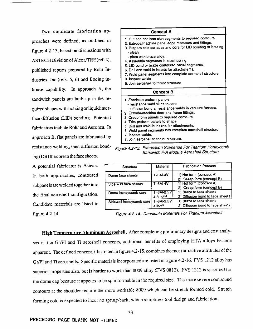
Two candidate fabrication ap-
proaches were defined, as outlined in
figure 4.2-13, based on discussions with
ASTECH Division of Alcoa/TRE (ref. 4),
published reports prepared by Rohr In-
dustries, Inc.(refs. 5, 6) and Boeing in-
house capability. In approach A, the
sandwich panels are built up in the re-
quired shapes with brazing or liquid inter-
face diffusion (LID) bonding. Potential
fabricators include Rohr and Aeronca. In
approach B, flat panels are fabricated by
resistance welding, then diffusion bond-
ing (DB) the core to the face sheets.
Concept A
1. Cut and hot form skin segments to required contours.2. Extrude/machine panel edge members and fittings.
3. Prepare skin surfaces and core for LID bonding or brazing- clean
- plate with braze alloy.4. Assemble segments in steel tooling.5. LID bond or braze contoured panel segments.6. Drill and weld-in inserts for attachments.
7. Weld panel segments into complete aeroshell structure.
8. Inspect welds.9. Join aeroshell to thrust structure.
Concept B
1. Fabricate preform panels- resistance weld skins to core
- diffusion bond at resistance welds in vacuum furnace.
2. Extrude/machine door and frame fittings.3. Creep form panels to required contours.
4. Trim preform panels to shape.5. Drill and weld-in inserts for attachments.
6. Weld panel segments into complete aeroshell structure.7. Inspect welds.8. Join aeroshell to thrust structure.
Figure 4.2-13. Fabrication Scenerios For Titanium HoneycombSandwich P/A Module Aeroshell Structure.
A potential fabricator is Astech.
In both approaches, contoured
subpanels are welded together into
the final aeroshell configuration.
Candidate materials are listed in
figure 4.2-14.
Structure Material Fabrication Process
Dome face sheets Ti-6AI-4V
Side wall face sheets
Dome honeycomb core
Sidewall honeycomb core
Ti-6AI-4V
Ti-3AI-2.5V
4-8 Ib/ft 3
Ti-3AI-2.5V4 Ib/ft 3
1) Hot form (concept A)
2) Creep form Iconcept B)1 ) Hot form (concept A)
2) Creep form Iconcept B)1) Braze to face sheets
2) Diffusion bond to face sheets
1) Braze to face sheets
2) Diffusion bond to face sheets
Figure 4.2-14. Candidate Materials For Titanium Aeroshell
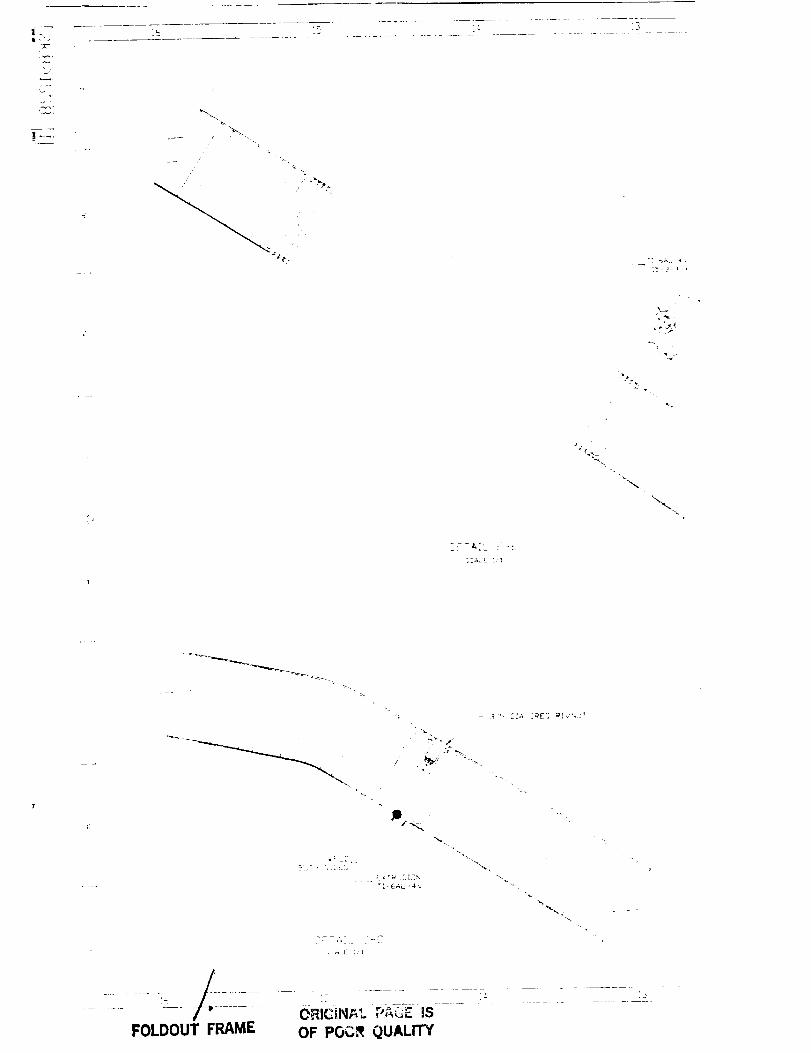
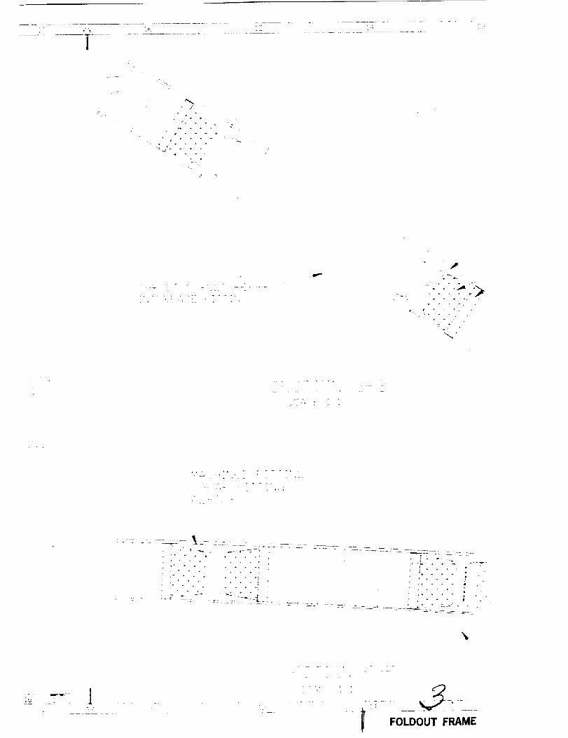
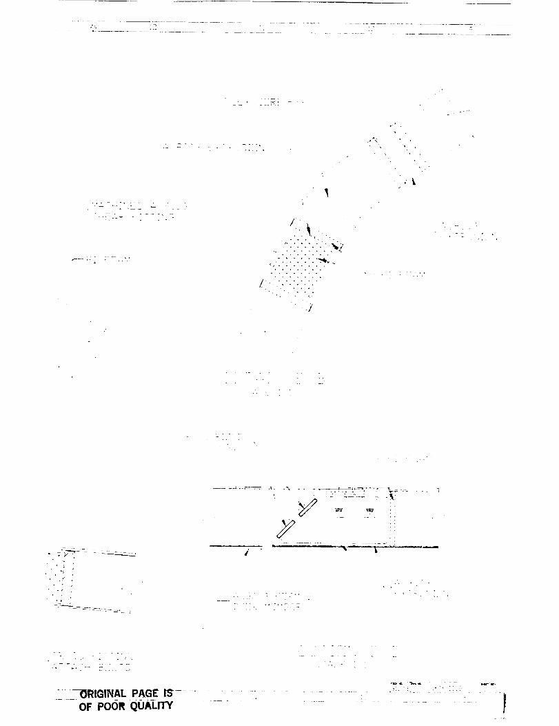
High Temoerature Aluminum Aeroshell, After completing preliminary designs and cost analy-
ses of the Gr/PI and Ti aeroshell concepts, additional benefits of employing HTA alloys became
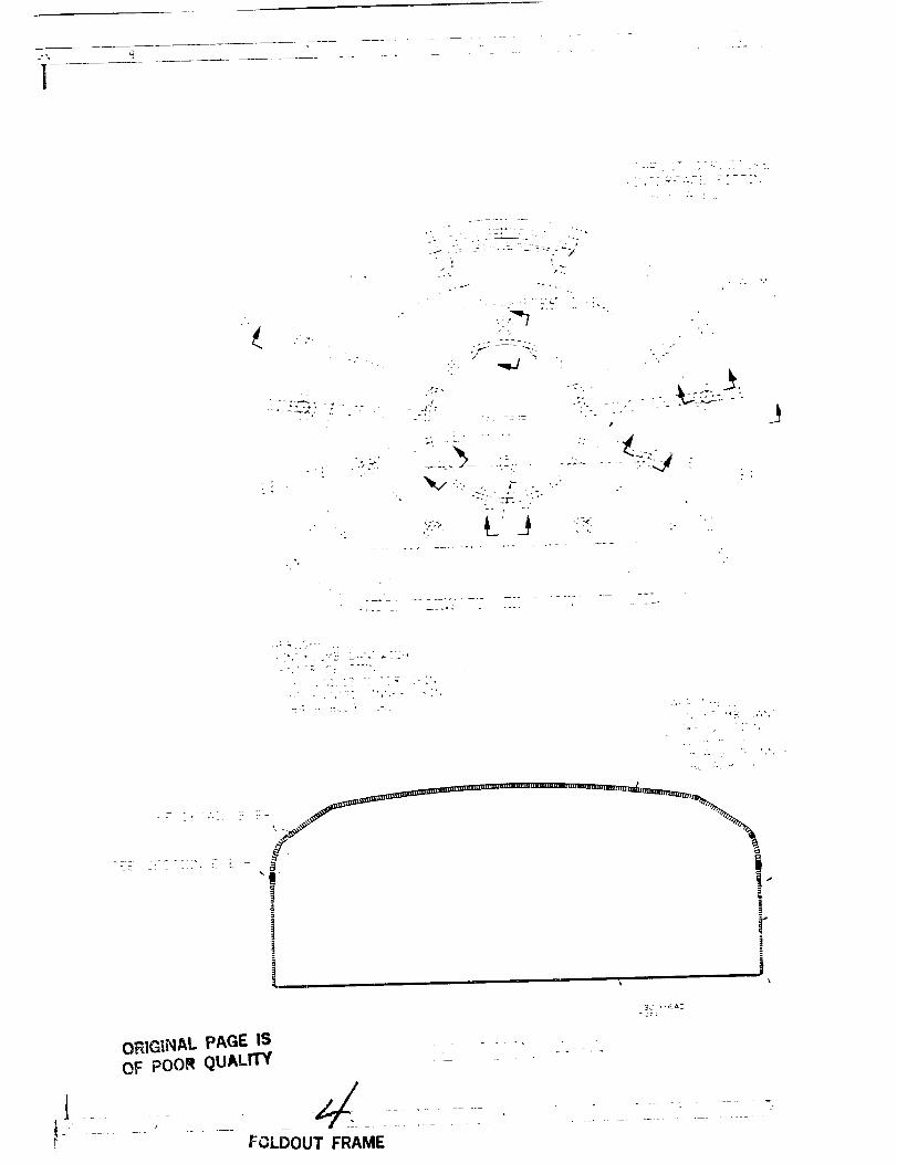
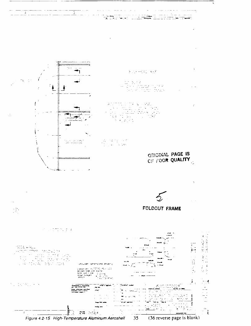
apparent. The defined concept, illustrated in figure 4.2-15, combines the most attractive attributes of the
Gr/PI and Ti aeroshells. Specific materials incorporated are listed in figure 4.2-16. FVS 1212 alloy has
superior properties also, but is harder to work than 8009 alloy (FVS 0812). FVS 1212 is specified for
the dome cap because it appears to be spin formable in the required size. The more severe compound
contours at the shoulder require the more workable 8009 which can be stretch formed cold. Stretch
forming cold is expected to incur no spring-back, which simplifies tool design and fabrication.
PRECEDING PAGE BLA,_K NOT FILMED
33

This page intentionally left blank
34
I
ms:
L_
__v --
xi ....
I
I
-- l -
4
d
I
FOLDOUT FRAME
pRECEDING PAGE BLANK NOT FIL

"13 i'_ .'_E_,_
D,--- .....
_ i_ . _ _ • __
i i:i::!::i: i:! l
a
\ - k , - , • , ,
j , , •
:'"'" '.'-"-_i. ' ": _ :_ :" "'-
..... OF POOR QUALITY | FOLDOUT FRAME OF POOR QUALITY

4
_ ÷ ._
t• ( _ * * •
_e_.-
- p
• • . _
Z -- -- -
'-- .... I -_-'- FOLDOUT FRAME

/i .....
o •
" .r
/....... :m_ ,
OF POOR QUALITY .... i

-I
4
" Z
:I _ --
J'2 •
3.Z:"
__.._:_.......::__:,j_I "... _ .."
-. .<. . ._:.
ORIGINAL PAGE IS
OF pOOR QUALITY
....... FOLDOUT FRAME

[i -F,
ii.......g_
i!
,,,--_r,,,_,'_ PAGE IS
C_: i:OOR QUALITY
FOLCOUT FRAME
..... ,_.'*L=
L:
v r
_._,,.._ _ , '_ _ _ ._,','_'L-.: " ,- _ - " : - -
Figure 4.2-15. High-Temperature Aluminum Aeroshell 35 (36 reverse page is blank)

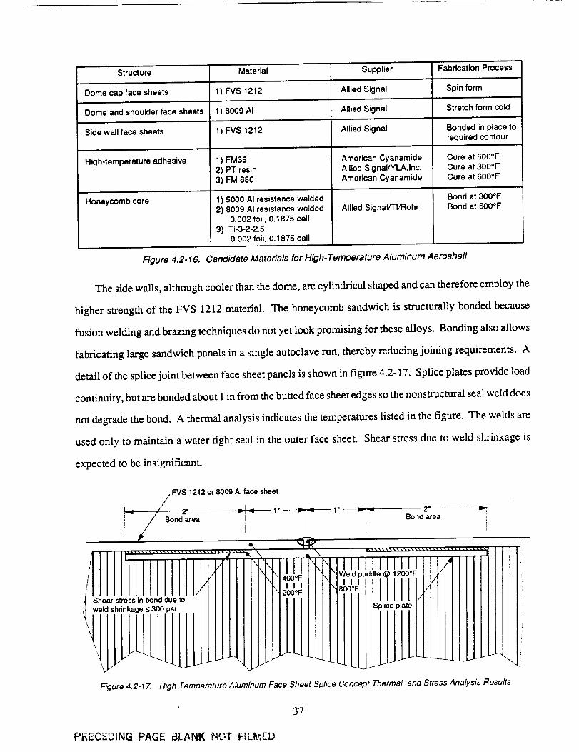
Structure '" Material Supplier Fabrication Process
Dome cap face sheets 1 ) FVS 1212 Allied Signal Spin form
Dome and shoulder face sheets 1) 8009 AI Allied Signal Stretch form cold
Side wall face sheets 1) FVS 1212 Allied Signal Bonded in place torequired contour
High-temperature adhesive f) FM35 American Cyanamide Cure at 600oF2) PT resin Allied Signal/YLA, Inc. Cure at 300°F
3) FM 680 American Cyanamide Cure at 600°F
Honeycomb core 1) 5000 AI resistance welded
2) 8009 AI resistance welded0.002 foil, 0.1875 cell
3) Ti-3-2-2.50.002 foil, 0.1875 cell
Allied Signal/TI/Rohr
Bond at 300°FBond at 600°F
Figure 4.2-16. Candidate Materials for High-Temperature Aluminum Aeroshe//
The side walls, although cooler than the dome, are cylindrical shaped and can therefore employ the
higher strength of the FVS 1212 material. The honeycomb sandwich is structurally bonded because
fusion welding and brazing techniques do not yet look promising for these alloys. Bonding also allows
fabricating large sandwich panels in a single autoclave run, thereby reducing joining requirements. A
detail of the splice joint between face sheet panels is shown in figure 4.2-17. Splice plates provide load
continuity, but are bonded about 1 in from the butted face sheet edges so the nonstructural seal weld does
not degrade the bond. A thermal analysis indicates the temperatures listed in the figure. The welds are
used only to maintain a water tight seal in the outer face sheet. Shear stress due to weld shrinkage is
expected to be insignificant.
• FVS 1212 or 8009 AI face sheet
nd2area
I
/ (/[l[llrJijjtrjjr
1 N
'_ Bond area i[)
00*F e puddle@ 1200°F
"°' IIrlil
-
ii
I
Figure 4.2-17. High Temperature Aluminum Face Sheet Splice Concept Thermal and Stress Analysis Results
37
PRECEDING PAGE BLANK NGT FILI_'],ED
A HTA alloy is desired for the honeycomb core because a conventional aluminum core would be
annealed to low strength during the time at bonding temperatures. The higher thermal conductivity of
aluminum makes it a better core material than titanium for this concept because it conducts heat away
from the external face sheet better, keeping the external temperature within material limits. HTA
honeycomb core is under development. We understand Allied-Signal is supplying Texas Instruments
with material for roiling into foil down to 2 mils thick, which is then formed and resistance welded into
core at Rohr Industries.
Propellant line door frames in the dome will be 8009 A1 for its thermal capability and so it can be
bonded with high-temperature adhesives. Door frames in the sidewalls, which are cooler, will be 7475
A1 which can be superplastic formable from sheet for reduced cost and bonded in place with
bismaleimide (BMI) adhesive at a lower cure temperature for further cost reduction.
Several candidate bonding adhesives are listed in figure 4.2-16. The PT resin has the benefit of
curing at a lower temperature than the others but achieves similar glass transition temperature (Tg)
values. This resin is in development, but research quantities are expected to be available. FM 680 is a
well established polyimide adhesive.
38
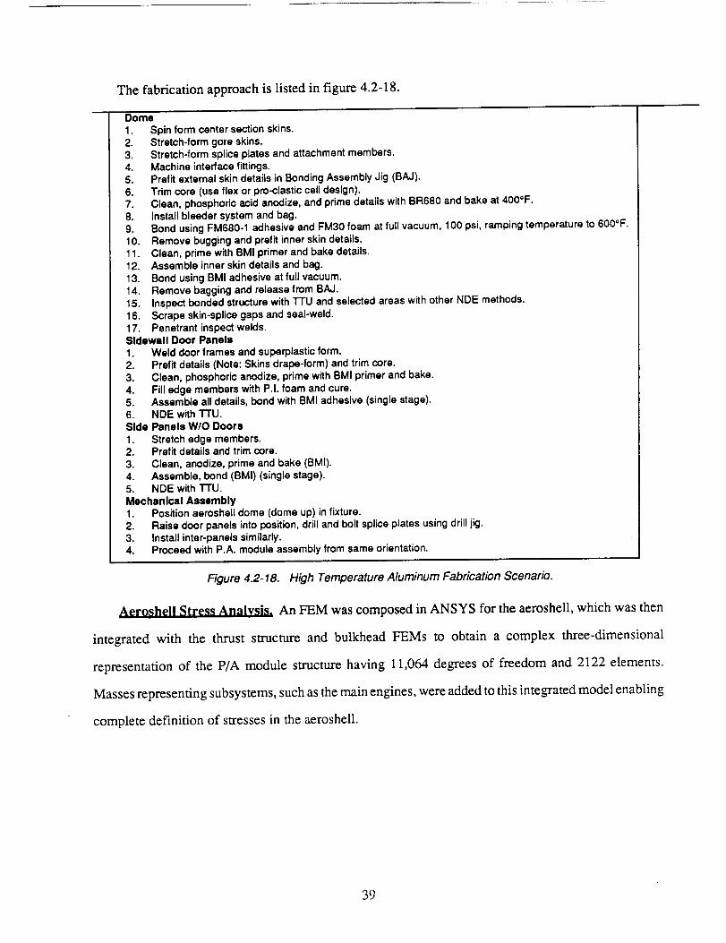
The fabrication approach is listed in figure 4.2-18.
Dome
1. Spin form center section skins.2. Stretch-form gore skins.3. Stretch-form splice plates and attachment members.4. Machine interface fittings.
5. Prefit external skin details in Bonding Assembly Jig (BAJ).6. Trim core (use flex or pro-clastJc cell design).7. Clean, phosphoric acid anodize, and prime details with BR680 and bake at 400*F.
8. Install bleeder system and bag.9. Bond using FM680-1 adhesive and FM30 foam at full vacuum, 100 psi, ramping temperature to 600°F.
10. Remove bugging and prefit inner skin details.11. Clean, prime with BMI primer and bake details.
12. Assemble inner skin details and bag.13. Bond using BMI adhesive at full vacuum.14. Remove bagging and release from BAJ.
15. Inspect bonded structure with "I-I'U and selected areas with other NDE methods.
16. Scrape skin-splice gaps and seal-weld.17. Penetrant inspect welds.Sidewall Door Panels
1. Weld door frames and superplastic form.
2. Prefit details (Note: Skins drape-form) and trim core.3. Clean, phosphoric anodize, prime with BMI primer and bake.
4. Fill edge members with P.I. foam and cure.5. Assemble all details, bond with BMI adhesive (single stage).6. NDE with TTU.Side Panels W/O Doors
1. Stretch edge members.2. Prefit details and trim core.
3. Clean, anodize, prime and bake (BMI).4. Assemble, bond (BMI) (single stage).5. NDE with "/-FU.
Mechanical Assembly1. Position aeroshell dome (dome up) in fixture.
2. Raise door panels into position, drill and bolt splice plates using drill jig.3. Install inter-panels similarly.4. Proceed with P.A. module assembly from same orientation.
Figure 4.2-18. High Temperature Aluminum Fabrication Scenario.
Aeroshell Stress Analysis. An FEM was composed in ANSYS for the aeroshell, which was then
integrated with the thrust structure and bulkhead FEMs to obtain a complex three-dimensional
representation of the P/A module structure having 11,064 degrees of freedom and 2122 elements.
Masses representing subsystems, such as the main engines, were added to this integrated model enabling
complete definition of stresses in the aeroshell.
39
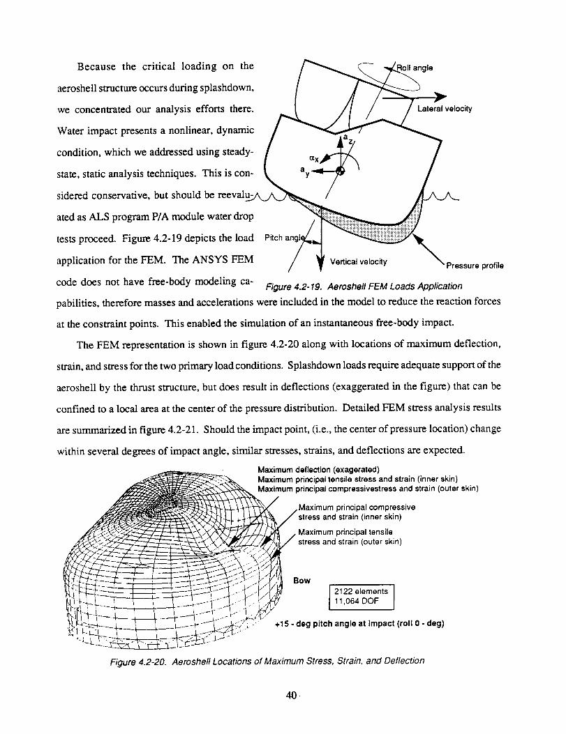
Because the critical loading on the angle
aeroshell structure occurs during splashdown,
we concentrated our analysis efforts there. Lateral velocity
Water impact presents a nonlinear, dynamic
condition, which we addressed using steady-
state, static analysis techniques. This is con-
sidered conservative, but should be reevalu-
ated as ALS program P/A module water drop
tests proceed. Figure 4.2-19 depicts the load Pitch
application for the FEM. The ANSYS FEM Verticalvelocity Pressureprofile
code does not have free-body modeling ca- Figure 4.2-19. Aeroshell FEM Loads Application
pabilities, therefore masses and accelerations were included in the model to reduce the reaction forces
at the constraint points. This enabled the simulation of an instantaneous free-body impact.
The FEM representation is shown in figure 4.2-20 along with locations of maximum deflection,
strain, and stress for the two primary loadconditions. Splashdown loads require adequate support of the
aeroshell by the thrust structure, but does result in deflections (exaggerated in the figure) that can be
confined to a local area at the center of the pressure distribution. Detailed FEM stress analysis results
are summarized in figure 4.2-21. Should the impact point, (i.e., the center of pressure location) change
within several degrees of impact angle, similar stresses, strains, and deflections are expected.
_.. _ .... ---r--- __'.'\F?! Bow
Maximum deflection (exagerated)
Maximum principal tensile stress and strain (inner skin)Maximum principal compressivestress and strain (outer skin)
Maximum principal compressive;tress and strain (inner skin)
Maximum principal tensile
stress and strain (outer skin)
2122 elements11,064 DOF
+15 - deg pitch angle at Impact (roll 0 - deg)
Figure 4.2-20. Aeroshell Locations of Maximum Stress, Strain, and Deflection
0,
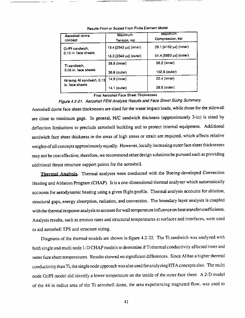
Results From or Scaled From Finite Element Model
Aeroshell dome
concept
Gr/PI sandwich,0.10 in. face sheets
Ti sandwich,0.05 in. face sheets
Hi-temp AI sandwich, 0.13in. face sheets
Maximum
Tension, ksi
19.4 [294214£] (inner)
18.3 [2346 I_] (outer)
38.8 (inner)
36.6 (outer)
14.9 (inner)
14.1 (outer)
Maximum
Compression, ksi
29.1 [4162 _] (inner)
51.4 [5650 Is_] (outer)
58.2 (inner)
102.8 (outer)
22.4 (inner)
39.5 (outer)
Final Aeroshell Face Sheet Thicknesses
Figure 4.2-21. Aeroshell FEM Analysis Results and Face Sheet Sizing Summary.
Aeroshell dome face sheet thicknesses are sized for the water impact loads, while those for the sidewall
are close to minimum gage. In general, H/C sandwich thickness (approximately 3-in) is sized by
deflection limitations to preclude aeroshell buckling and to protect internal equipment. Additional
sandwich face sheet thickness in the areas of high stress or strain are required, which affects relative
weights of all concepts approximately equally. However, locally increasing outer face sheet thicknesses
may not be cost effective; therefore, we recommend other design solutions be pursued such as providing
additional thrust structure support points for the aeroshell.
Thermal Analysis. Thermal analyses were conducted with the Boeing-developed Convection
Heating and Ablation Program (CHAP). It is a one-dimensional thermal analyzer which automatically
accounts for aerodynamic heating using a given flight profile. Thermal analysis accounts for ablation,
structural gaps, energy absorption, radiation, and convection. The boundary layer analysis is coupled
with the thermal response analysis to account for wall temperature influence on heat transi'er coefficients.
Analysis results, such as erosion rates and structural temperatures at surfaces and interfaces, were used
to aid aeroshell TPS and structure sizing.
Diagrams of the thermal models are shown in figure 4.2-22. The Ti sandwich was analyzed with
both single and multi node 1-D CHAP models to determine ifTi thermal conductivity affected inner and
outer face sheet temperatures. Results showed no significant differences. Since A1 has a higher thermal
conductivity than Ti, the single node approach was also used for analyzing HTA concepts also. The multi
node Gr/PI model did identify a lower temperature on the inside of the outer face sheet. A 2-D model
of the 44-in radius area of the Ti aeroshell dome, the area experiencing stagnated flow, was used to
41
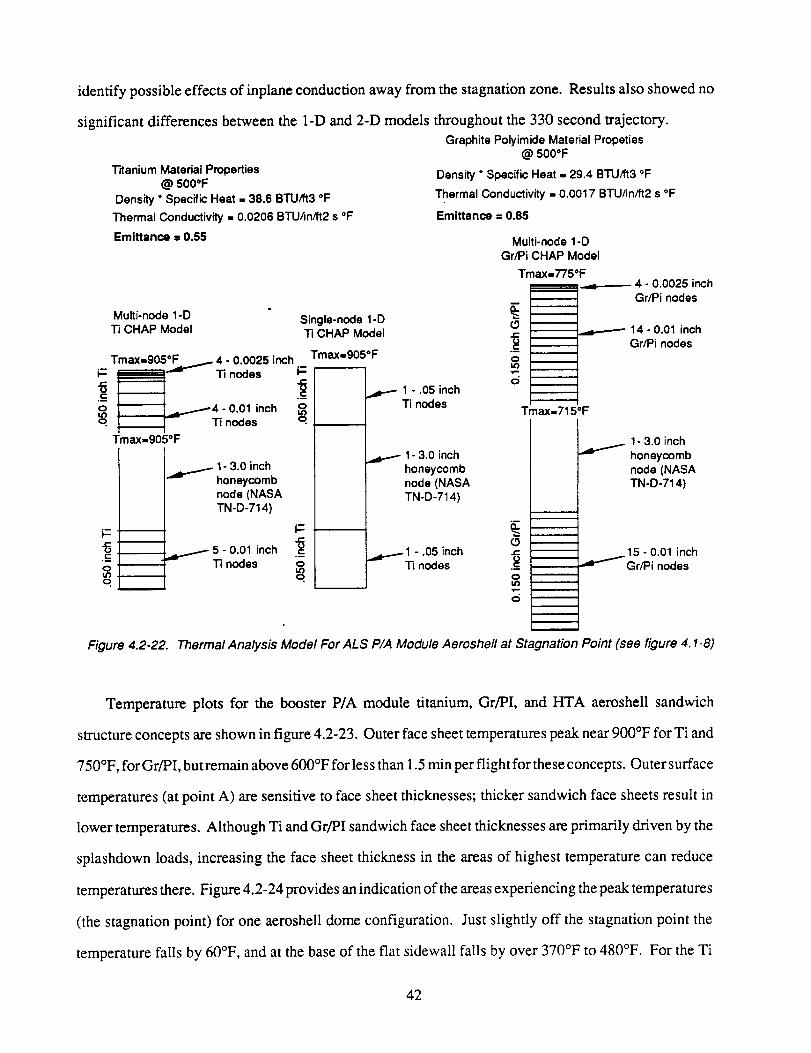
identify possible effects of inplane conduction away from the stagnation zone. Results also showed no
Titanium Material Properties@ 500*F
Density * Specific Heat = 38.6 BTU/ft3 *F
Thermal Conductivity = 0.0206 BTUhn/ft2 s °F
Emittance = 0.55
significant differences between the 1-D and 2-D models throughout the 330 second trajectory.
Graphite Polyimide Material Propeties@ 5000F
Density * Specific Heat ,, 29.4 BTU/ft3 *F
Thermal Conductivity = 0.0017 BTU/infft2 s *F
Emittance = 0.85
Multi-node 1-D
Ti CHAP Model
Tmax=905*F A 4 - 0.0025 inchiT. _t ''_'_- Ti nodes
"8/
.¢::
o I,,........_4 - 0.01 inchtOo "ri nodes
• I
Tmax=905oF
Single-node 1-DTi CHAP Model
Tmax=905*F
q
1- 3.0 inchhoneycombnode (NASATN-D-714)
"8 .¢...
OtO .
o.
I--e.-
5 - 0.01 inch .-8Ti nodes o
tOq
l - .05 inch
Ti nodes
1- 3.0 inch
honeycombnode (NASA
TN-D-714)
_ 1 - .05 inch
Ti nodes
Multi-node 1-D
Gr/Pi CHAP Model
Tmax=775*F_ 4 - 0.0025 inch
m
.-8
tOm
Gr/Pi nodes
14- 0.01 inchGr/Pi nodes
Tmax=715*F
(3J_
._8OtO.I,m
d
w
m
m
m
1- 3.0 inch
honeycomb
node (NASATN-D-714)
15 - 0.01 inch_dv""'_ Gr/Pi nodes
Figure 4.2-22. Thermal Analysis Model For ALS PIA Module Aeroshefl at Stagnation Point (see figure 4. I-8)
Temperature plots for the booster P/A module titanium, Gr/PI, and HTA aeroshell sandwich
structure concepts are shown in figure 4.2-23. Outer face sheet temperatures peak near 900°F for Ti and
750°F, for Gr/PI, but remain above 600°F for less than 1.5 min per flight for these concepts. Outer surface
temperatures (at point A) are sensitive to face sheet thicknesses; thicker sandwich face sheets result in
lower temperatures. Although Ti and Gr/PI sandwich face sheet thicknesses are primarily driven by the
splashdown loads, increasing the face sheet thickness in the areas of highest temperature can reduce
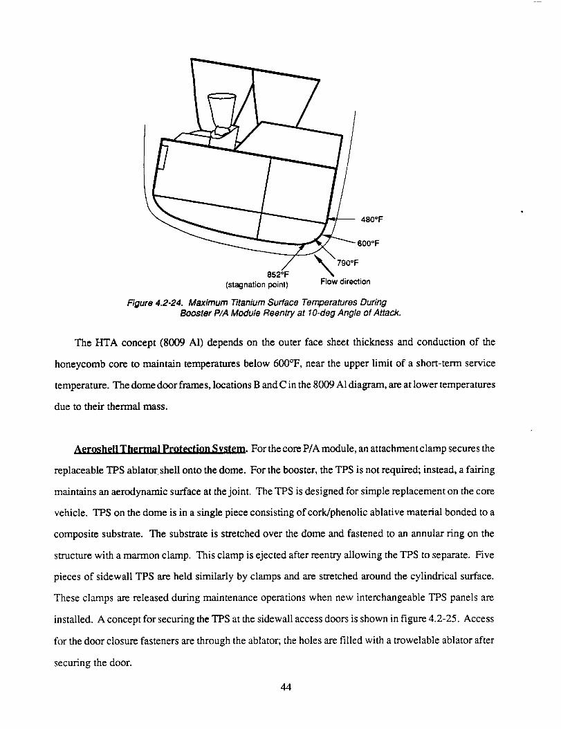
temperatures there. Figure 4.2-24 provides an indication of the areas experiencing the peak temperatures
(the stagnation point) for one aeroshell dome configuration. Just slightly off the stagnation point the
temperature fails by 60°F, and at the base of the flat sidewall falls by over 370°F to 480°F. For the Ti
42
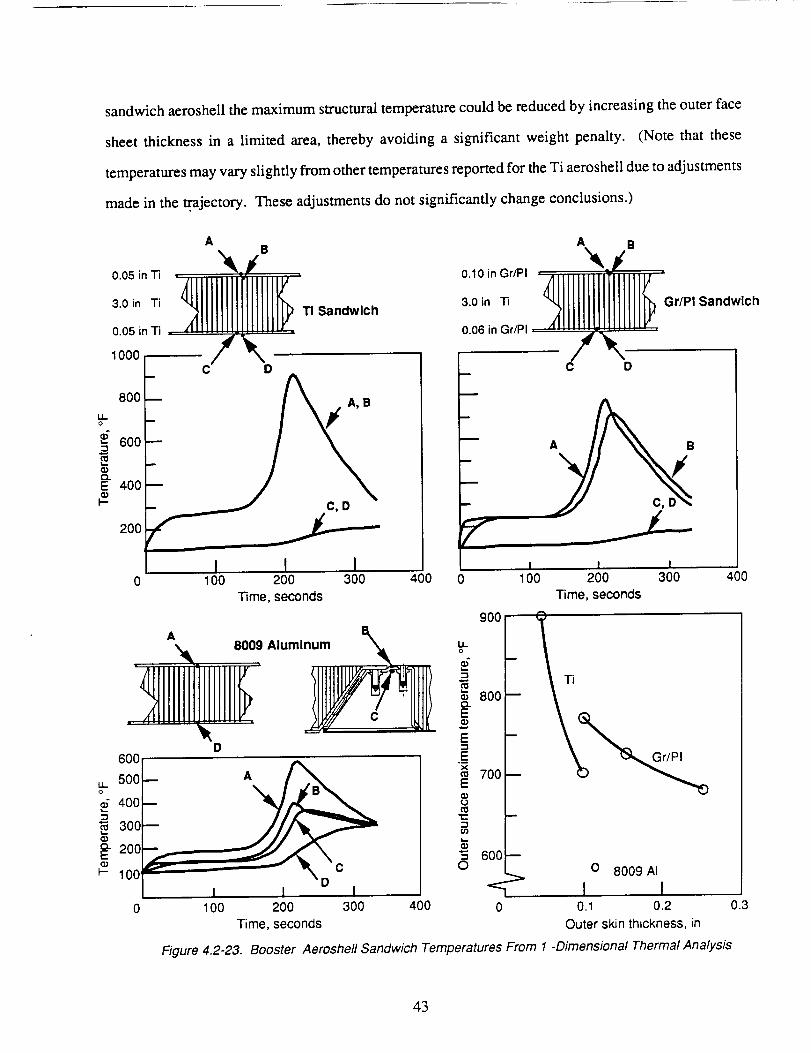
sandwich aeroshell the maximum structural temperature could be reduced by increasing the outer face
sheet thickness in a limited area, thereby avoiding a significant weight penalty. (Note that these
temperatures may vary slightly from other temperatures reported for the Ti aeroshell due to adjustments
made in the .trajectory. These adjustments do not significantly change conclusions.)
AB
o053.0 in Ti TI Sandwich
0.05 in Ti ........ . .........
1000 [
A B
0.10 inGr/PI _JN_
3.0 in Ti _Gr/PI Sandwich
0.06 in Gr/PI
8OO
IIo
g 600_=
_" 400
200
A, B
I II0 100 200 300 400
Time, seconds
Aluminum
8009
60(
A
A B
C
I300
I I -0 100 200 400 0.1 0.2
Time, seconds Outer skin thickness, in
I0 100 200 300
Time, seconds
°u'_g°°t= Ti
800
°f7oo
$"5O O 8009 AI
1 I0
Figure 4.2-23. Booster Aeroshefl Sandwich Temperatures From 1 -Dimensional Thermal Analysis
4OO
0.3
43
-- 480OF
790°F852°F
(stagnationpoint) Flowdirection
FTgure4.2-24. Maximum Titanium Surface Temperatures DuringBooster P/A Module Reentry at 10-deg Angle of Attack.
The HTA concept (8009 A1) depends on the outer face sheet thickness and conduction of the
honeycomb core to maintain temperatures below 600°F, near the upper limit of a short-term service
temperature. The dome door frames, locations B and C in the 8009 A1 diagram, are at lower temperatures
due to their thermal mass.
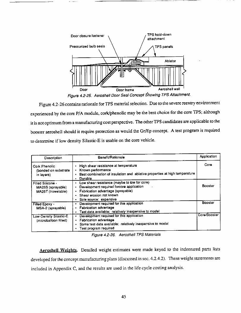
Aeroshell Thermal Protection System. For the core P/A module, an attachment clamp secures the
replaceable TPS ablator shell onto the dome. For the booster, the TPS is not required; instead, a fairing
maintains an aerodynamic surface at the joint. The TPS is designed for simple replacement on the core
vehicle. TPS on the dome is in a single piece consisting of cork/phenolic ablative material bonded to a
composite substrate. The substrate is stretched over the dome and fastened to an annular ring on the
structure with a marmon clamp. This clamp is ejected after reentry allowing the TPS to separate. Five
pieces of sidewall TPS are held similarly by clamps and are stretched around the cylindrical surface.
These clamps are released during maintenance operations when new interchangeable TPS panels are
installed. A concept for securing the TPS at the sidewall access doors is shown in figure 4.2-25. Access
for the door closure fasteners are through the ablator; the holes are filled with a trowelable ablator after
securing the door.
44
Door closure fastener TPS hold-down
Pressurized bulb seals _ / attachment
t i
tllllllliiDoor Door frame Aeroshell wall
Figure 4.2-25. Aeroshe/I Door Seal Concept Showing TPS Attachment.
Figure 4.2-26 contains rationale for TPS material selection. Due to the severe reentry environment
experienced by the core P/A module, cork/phenolic may be the best choice for the core TPS; although
it is not optimum from a manufacturing cost perspective. The other TPS candidates are applicable to the
booster aeroshell should it require protection as would the Gr/Ep concept. A test program is required
to determine if low density Silastic-E is usable on the core vehicle.
Description Benefit/Rationale Application
Cork Phenolic • High shear resistance at temperature Core(bonded on substrate • Known performance
in layers) • Best combination of insulation and ablative properties at high temperature• Durable
Booster
Filled Silicone -
MA25S (sprayable)
MA25T (trowelable)
Filled Epoxy -
MSA-2 (sprayable)
Low-Oensity Si|astic-E(microballoon filled)
• Low shear resistance (maybe to low for core)• Development required forcore application
• Fabrication advantage (sprayable)• Shear erosion not known
• Sole source: expensive
• Development required for this application• Fabrication advantage
• Test data available: relatively inexpensive to model• Oeve|opment required for this application• Fabrication advantage• Some test data available: relatively inexpensive to model
• Test program required
Booster
Core/Booster
Figure 4.2-26. Aeroshell TPS Materials
Aeroshell Weights. Detailed weight estimates were made keyed to the indentured parts lists
developed for the concept manufacturing plans (discussed in sec. 4.2.4.2). These weight statements are
included in Appendix C, and the results are used in the life cycle costing analysis.
45
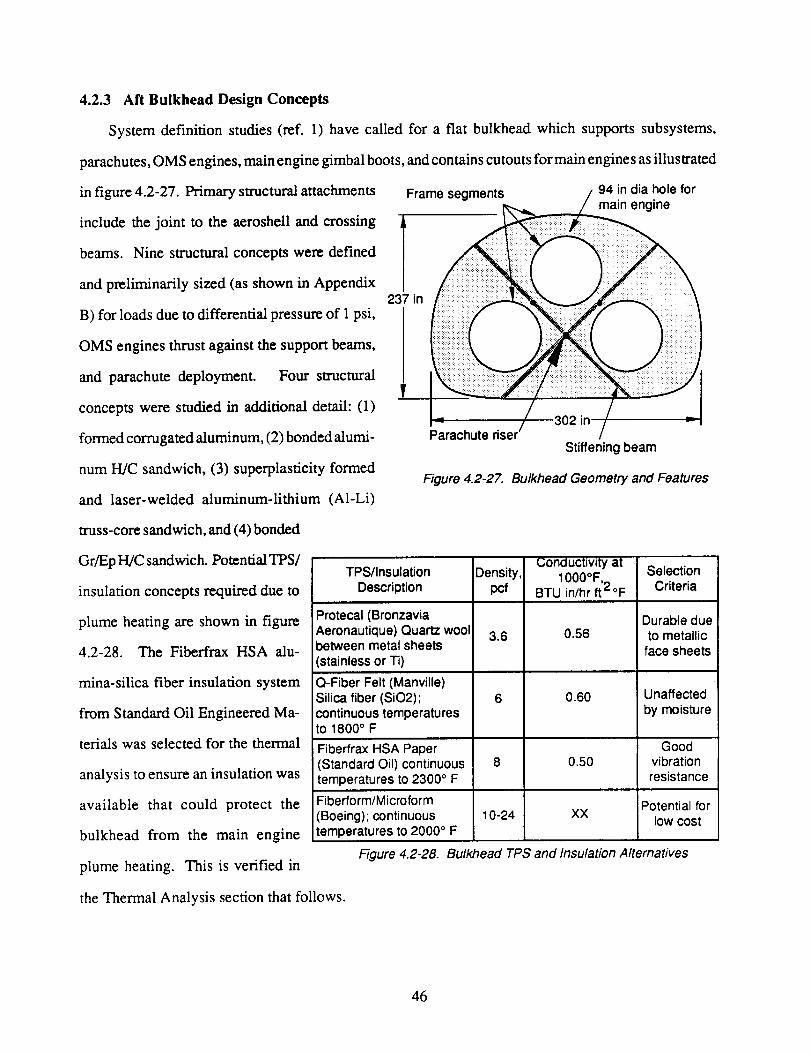
4.2.3 Aft Bulkhead Design Concepts
System definition studies (ref. 1) have called for a flat bulkhead which supports subsystems,
parachutes, OMS engines, main engine gimbal boots, and contains cutouts for main engine s as illustrated
in figure 4.2-27. Primary structural attachments
include the joint to the aeroshell and crossing
/beams. Nine structural concepts were defined
and preliminarily sized (as shown in Appendix237 in
B) for loads due to differential pressure of 1 psi,
Frame segments 94 in dia hole formain engine
OMS engines thrust against the support beams,
and parachute deployment. Four structural
concepts were studied in additional detail: (1)
formed corrugated aluminum, (2) bonded alumi-
num H/C sandwich, (3) superplasticity formed
and laser-welded aluminum-lithium (A1-Li)
Parachute rise=Stiffening beam
Figure 4.2-27. Bulkhead Geometry and Features
truss-core sandwich, and (4) bonded
Gr/Ep H/C sandwich. Potential TPS/
insulation concepts required due to
plume heating are shown in figure
4.2-28. The Fiberfrax HSA alu-
mina-silica fiber insulation system
from Standard Oil Engineered Ma-
terials was selected for the thermal
analysis to ensure an insulation was
available that could protect the
bulkhead from the main engine
plume heating. This is verified in
TPS/InsulationDescription
Conductivity atDensity, 1000°F,
pcf BTU in/hr ft2°F
Protecal (BronzaviaAeronautique) Quartz woolbetween metal sheets(stainless or Ti)
Q-Fiber Felt (Manville)Silica fiber (SiO2);continuous temperaturesto 1800° F
Fiberfrax HSA Paper(Standard Oil) continuoustemperatures to 2300 ° F
Fiberform/Microform(Boeing); continuoustemperatures to 2000 ° F
Figure 4.2-28.
3.6 0.56
6 0.60
8 0.50
10-24 XX
SelectionCriteria
Durable dueto metallicface sheets
Unaffectedby moisture
Goodvibrationresistance
Potential forlow cost
Bulkhead TPS and Insulation Alternatives
the Thermal Analysis section that follows.
46
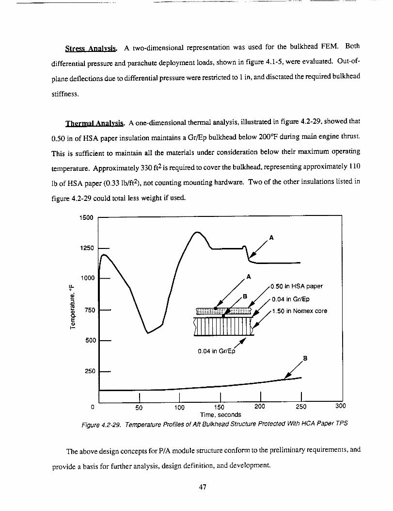
_. A two-dimensionalrepresentationwasusedfor the bulkheadFEM. Both
differentialpressureandparachutedeploymentloads,shownin figure4.1-5,wereevaluated.Out-of-
planedeflectionsduetodifferentialpressurewererestrictedto 1 in,anddisctatedtherequiredbulkhead
stiffness.
Thermal Analysis. A one-dimensional thermal analysis, illustrated in figure 4.2-29, showed that
0.50 in of HSA paper insulation maintains a Gr/Ep bulkhead below 200°F during main engine thrust.
This is sufficient to maintain all the materials under consideration below their maximum operating
temperature. Approximately 330 ft 2 is required to cover the bulkhead, representing approximately 110
lb of HSA paper (0.33 lb/ft2), not counting mounting hardware. Two of the other insulations listed in
figure 4.2-29 could total less weight if used.
1500
LI.O
EG)
I---
1250
1000
750
500
250
___ / A/0.50 in.SApaper
_ _ ] Y_ili::::_;_::::iii::ii_i!::i::i::!::i::i::i::i::i::i:i::i::iii::i_/jl¢/1.50in Nomex core
k.-' /llmmltmImlk"-- /
0.04 in Gr/EpB
0
Figure 4.2-29.
I I I I50 100 150 200 250 300
Time, seconds
Temperature Profiles of Aft Bulkhead Structure Protected With HCA Paper TPS
The above design concepts for P/A module structure conform to the preliminary requirements, and
provide a basis for further analysis, design definition, and development.
47
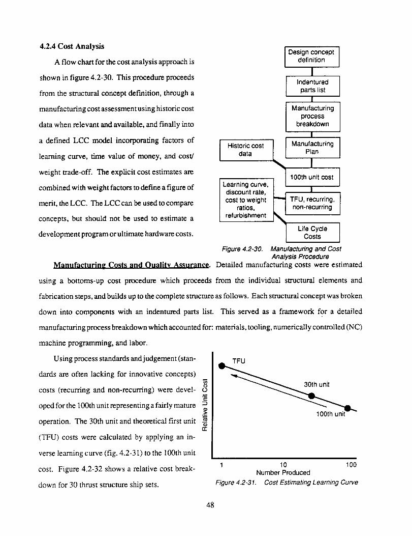
4.2.4 Cost Analysis
A flow chart for the cost analysis approach is
shown in figure 4.2-30. This procedure proceeds
from the structural concept definition, through a
manufacturing cost assessment using historic cost
data when relevant and available, and finally into
a defined LCC model incorporating factors of
learning curve, time value of money, and cost/
weight trade-off. The explicit cost estimates are
combined with weight factors to define a figure of
merit, the LCC. The LCC can be used to compare
concepts, but should not be used to estimate a
development program or ultimate hardware costs.
Historic costdata
Learning curve,discount rate,cost to weight
ratios,refurbishment
Figure 4.2-30.
I Design conceptdefinition
I
Indentured Iparts listI
Manufacturingprocess
breakdown
I
L Manufacturing
["_ TFU, recurring,
non-recurring
I Lif_°CstYsCle ]
Manufacturing and CostAnalysis Procedure
Manufacturin_ Costs and Oualitv Assuranee. Detailed manufacturing costs were estimated
using a bottoms-up cost procedure which proceeds from the individual structural elements and
fabrication steps, and builds up to the complete structure as follows. Each structural concept was broken
down into components with an indentured parts list. This served as a framework for a detailed
manufacturing process breakdown which accounted for: materials, tooling, numerically controlled (NC)
machine programming, and labor.
Using process standards and judgement (stan-
dards are often lacking for innovative concepts)
costs (recurring and non-recurring) were devel-
oped for the 100th unit representing a fairly mature
operation. The 30th unit and theoretical first unit
(TFU) costs were calculated by applying an in-
verse learning curve (fig. 4.2-31) to the 100th unit
cost. Figure 4.2-32 shows a relative cost break-
down for 30 thrust structure ship sets.
rr
TFU
1 10 100Number Produced
Figure 4.2-31. Cost Estimating Learning Curve
48
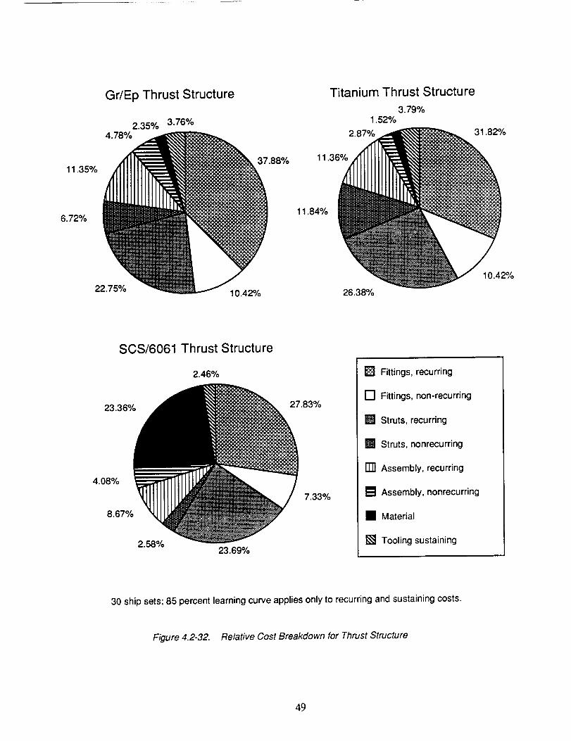
11.35%
6.72%
Gr/Ep Thrust Structure
2.35%
22.75%
Titanium Thrust Structure
3.79%3.76% 1.52%
2.8_ 31.82%
11.36_
.88% 26'38%_
11.84%
10.42%
SCS/6061 Thrust Structure
8.67%
2.46%
.83%
_ 7.33%
23.69%
[] Fittings, recurring
[] Fittings, non-recurring
• Struts, recurring
• Struts, nonrecurring
[] Assembly, recurring
• Assembly, nonrecurring
• Material
[] Tooling sustaining
30 ship sets; 85 percent learning curve applies only to recurring and sustaining costs.
Figure 4.2-32. Relative Cost Breakdown for Thrust Structure
49
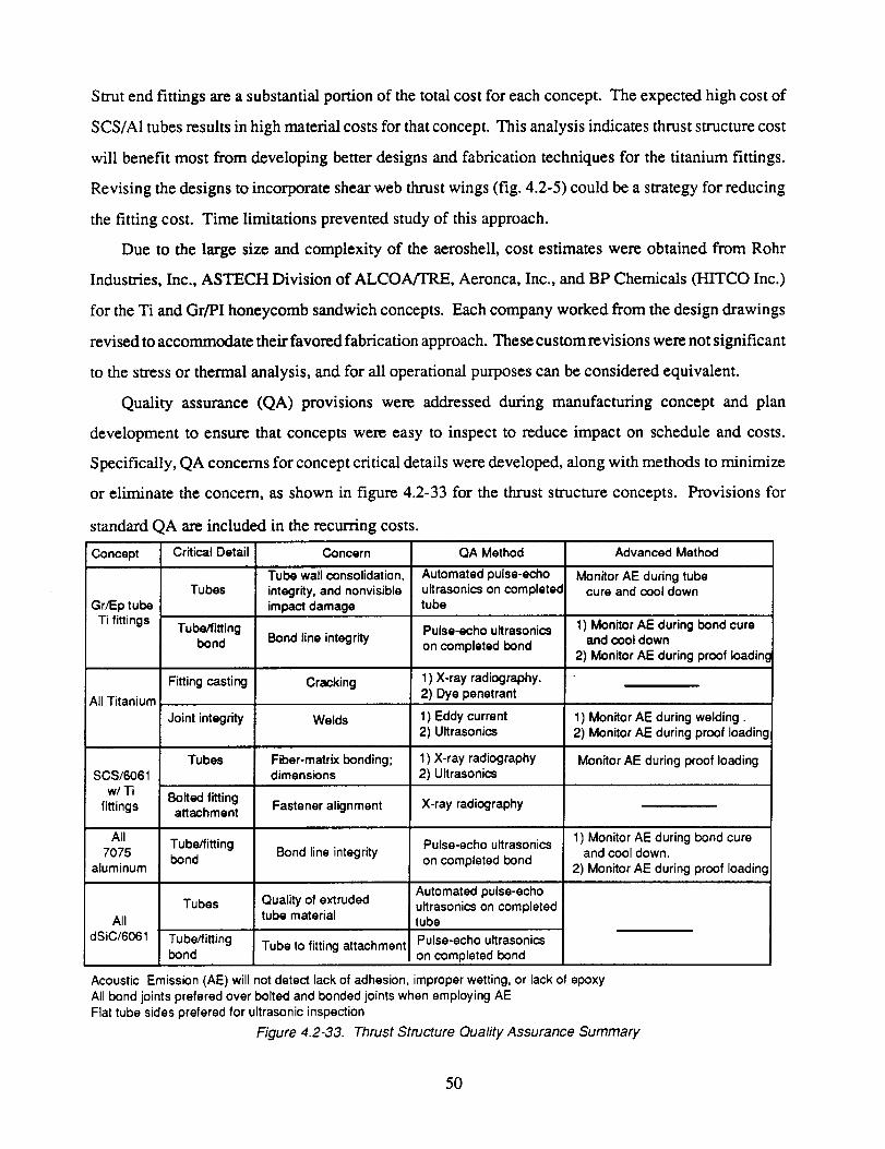
Strut end fittings are a substantial portion of the total cost for each concept. The expected high cost of
SCS/A1 tubes results in high material costs for that concept. This analysis indicates thrust structure cost
will benefit most from developing better designs and fabrication techniques for the titanium fittings.
Revising the designs to incorporate shear web thrust wings (fig. 4.2-5) could be a strategy for reducing
the fitting cost. Time limitations prevented study of this approach.
Due to the large size and complexity of the aeroshell, cost estimates were obtained from Rohr
Industries, Inc., ASTECH Division of ALCOA/TRE, Aeronca, Inc., and BP Chemicals (IMTCO Inc.)
for the Ti and Gr/PI honeycomb sandwich concepts. Each company worked from the design drawings
revised to accommodate their favored fabrication approach. These custom revisions were not significant
to the stress or thermal analysis, and for all operational purposes can be considered equivalent.
Quality assurance (QA) provisions were addressed during manufacturing concept and plan
development to ensure that concepts were easy to inspect to reduce impact on schedule and costs.
Specifically, QA concerns for concept critical details were developed, along with methods to minimize
or eliminate the concern, as shown in figure 4.2-33 for the thrust structure concepts. Provisions for
standard QA are included in the recurring costs.
Concept Critical Detail Concern QA Method Advanced Method
Tube wall consolidation, Automated pulse-echo Monitor AE during tubeTubes integrity, and nonvisible ultrasonics on completed cure and cool down
Gr/Ep tube impact damage tube
Ti fittings Tube/fitting Pulse-echo ultrasonics 1) Monitor AE during bond cure
bond Bond line integrity on completed bond and cool down2) Monitor AE during proof Ioadin¢
Fitting casting Cracking 1) X-ray radiography.2) Dye penetrant
All Titanium
Joint integrity Welds 1) Eddy current 1) Monitor AE during welding.2) Ultrasonics 2) Monitor AE during proof loading
Tubes Fiber-matrix bonding; 1) X-ray radiography Monitor AE during proof loadingSCS/6061 dimensions 2) Ultrasonics
w/Ti
fittings Fastener alignment X-ray radiography
All
7075aluminum
Bolted fittingattachment
Tube/fittingbond
Tubes
Tubeffi_ingbond
Bond lineintegrity
Quality of extrudedtube material
Tube to fitting attachment
All
dSiC/6061
Pulse-echo ultrasonics
on completed bond
Automated pulse-echoultrasonics on completedtube
Pulse-echo ultrasonics
on completed bond
1) Monitor AE during bond cureand cool down.
2) Monitor AE during proof loading
Acoustic Emission (AE) will not detect lack of adhesion, improper wetting, or lack of epoxy
All bond joints prefered over bolted and bonded joints when employing AE
Flat tube sides prefered for ultrasonic inspection
Figure 4.2-33. Thrust Structure Quality Assurance Summary
50
Life-Cycle Cost Analysis. LCC analyses were conducted to assess the system effects of cost and
performance variations in the design concepts. The structural concept options were evaluated based on
their benefit to launch system LCC. Because a full launch-system cost analysis is not only very costly,
but not necessary for this study, our analysis is incremental. System LCC sensitivities (cost model
factors) were calculated from the system LCC model. Weight enters as a debit to the cost estimates (i.e.,
structural weight higher than the reference configuration incurs an increased cost; structural weight
lower than the reference configuration incurs a reduced cost). The cost and weight (mass) estimates for
the structural concepts result in LCC differentials from the reference configuration (i.e., a delta LCC).
For comparison purposes, the delta LCCs (differences between the concept LCC and the reference
configuration) are the significant result, not the absolute LCC values derived.
The process for calculating LCC, outlined in figure 4.2-34, can be performed on a desktop computer
spreadsheet. Elements in shaded boxes represent data calculated or estimated during structural concept
definition. Elements in rounded boxes are model factors, and represent assumptions based on launch-
system economics. Therefore, LCC results depend on cost and weight estimates for each structural
concept compared, and on the LCC model factors assumed. These factors are:
Recurring cost:weight ratio: break-even between cost of hardware and resulting mass saved; numeri-
cally determined partial derivative calculated from the mission model for the entire launch system.
Design. development, test. and evaluation (DDT&E) cost:weight ratio: breakeven between cost of
development and resulting mass saved; numerically determined partial derivative calculated from the
mission model for the entire launch system.
Reusable hardware (H/W) ratio: number of times hardware is reused.
Units/flight ad_iustment: number of common structures on the launch vehicle determined from the ALS
mission model (2 or more P/A modules fly on each launch).
Flight rate adjustment: number of flights in the mission model.
Discoun_ factors: the time value of money; near term costs (non-recurring) are weighted higher than far
term costs (recurring).
51
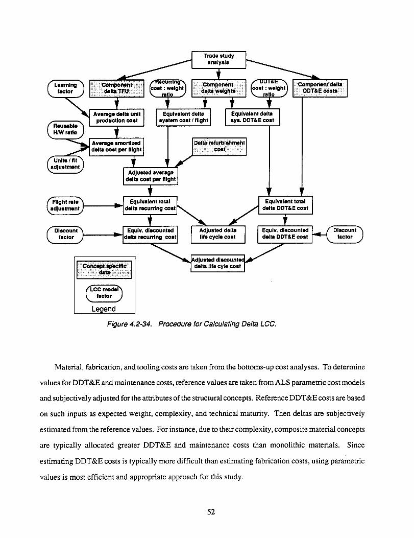
Trade study
analysis
ifactor ) I :: _llaT_iiii:,ili_ii:.:l k..... _ "'"1 I_ delta:welghts!i I _.... -"."""')
!- . I production COStI I''m cost/f,ioh,I I or"DDT,E_,t I
de,,co,,per.lO.tI |
_adJustment J , ! v /_,"- J I Adjusted average I
Ldelta cost per flight ]
I _mponsntdsltm,;;IOOTtecos._ I
Fllg ht ra ts_'_
Justment_
( Olscount_factor J
, Equivalent total L _ :2:iv;'s":_°_'tj
r.°,u..°.,.i i.o,..°,.°ou°,. o, oon, -Id,_'rac.r, n0co°,I ,,s=yclsco°t d_, DDT&EcostJ_._ factor j
_llb_AddJUsted dlscounte_ _
etta life cyle cost I
factor
Legend
Figure 4.2-34. Procedure for Calculating Delta LCC.
Material, fabrication, and tooling costs are taken from the bottoms-up cost analyses. To determine
values for DDT&E and maintenance costs, reference values are taken from ALS parametric cost models
and subjectively adjusted for the attributes of the structural concepts. Reference DDT&E costs are based
on such inputs as expected weight, complexity, and technical maturity. Then deltas are subjectively
estimated from the reference values. For instance, due to their complexity, composite material concepts
are typically allocated greater DDT&E and maintenance costs than monolithic materials. Since
estimating DDT&E costs is typically more difficult than estimating fabrication costs, using parametric
values is most efficient and appropriate approach for this study.
52
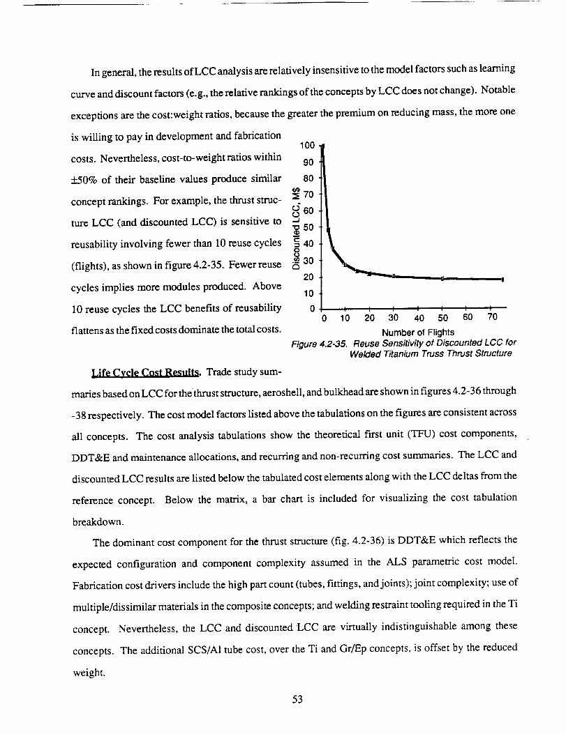
Ingeneral,theresuitsof LCCanalysisarerelativelyinsensitivetothemodelfactorssuchaslearning
curveanddiscountfactors(e.g.,therelativerankingsof theconceptsbyLCCdoesnotchange).Notable
exceptionsarethecost:weightratios,becausethegreaterthepremiumonreducingmass,themoreone
is willing to payin developmentandfabrication
costs.Nevertheless,cost-to-weightratioswithin
+_50% of their baseline values produce similar
concept rankings. For example, the thrust struc-
ture LCC (and discounted LCC) is sensitive to
reusability involving fewer than 10 reuse cycles
(flights), as shown in figure 4.2-35. Fewer reuse
cycles implies more modules produced. Above
10 reuse cycles the LCC benefits of reusability
flattens as the fixed costs dominate the total costs.
Figure 4.2-35.
I I I t I I
20 30 40 50 60 70
Number of FlightsReuse Sensitivity of Discounted LCC for
Welded Titanium Truss Thrust Structure
Life Cycle Cost Results. Trade study sum-
maries based on LCC for thethrust structure, aeroshell, and bulkhead are shown in figures 4.2-36 through
-38 respectively. The cost model factors listed above the tabulations on the figures are consistent across
all concepts. The cost analysis tabulations show the theoretical first unit (TFU) cost components,
DDT&E and maintenance allocations, and recurring and non-recurring cost summaries. The LCC and
discounted LCC results are listed below the tabulated cost elements along with the LCC deltas from the
reference concept. Below the matrix, a bar chart is included for visualizing the cost tabulation
breakdown.
The dominant cost component for the thrust structure (fig. 4.2-36) is DDT&E which reflects the
expected configuration and component complexity assumed in the ALS parametric cost model.
Fabrication cost drivers include the high part count (tubes, fittings, and joints); joint complexity; use of
multiple/dissimilar materials in the composite concepts; and welding restraint tooling required in the Ti
concept. Nevertheless, the LCC and discounted LCC are virtually indistinguishable among these
concepts. The additional SCS/A1 tube cost, over the Ti and Gr/Ep concepts, is offset by the reduced
weight.
53
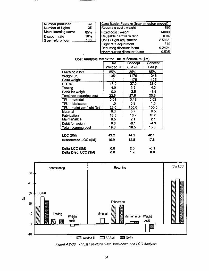
I Number produced
Number of flightsMaint learning curveDiscount rate_; oer refurb hour
3225
85%10%100
Cost Model Factors (from mission model)Recurring cost : weight 150
Fixed cost : weight 14000Reusable hardware ratio 0.04Units / flight adjustment 2.5065Flight rate adjustment 310Recurring discount factor 0.2424Ngnrecurrino discount factor 0.535
Cost Analysis Matrix for Thrust StructureRef
Welded Ti85%1351
018.04.90.0
22.90.011.0
25.00.3
18.50.50.0
19.3
ConceptSCS/AI
85%1176-17527.03.2
-2.527.80.180.9
100.05.716.72.1-8.116.5
SM)ConceptGr/Ep85%1246-10523.04.3-1.5
25.80.021.0
100.00.5
18.62.1
-4.916.3
Learning curveWeight (Ib)Delta weightDDT&EToolingDebit for weightTotal non-recurring costTFU - materialTFU - fabricationTFU - maint per flight (hr)Material
FabricationMaintenance
Debit for weightTotal recurring cost
LCC ($M) 42.2 44.2 42.1Discounted LCC ($M) 16.9 18.8 17.8
Delta LCC ($M) 0.0 2.0 -0.1Delta Disc. LCC ($M) 0.0 1.9 0.8
MS
5O
4O
30
2O
10
-10
Nonrecurring
DDT&E
WeightdebitL_t--- I
WeldedTi
Figure 4.2-36.
Material
q__
Recurring
Fabrication
l_ Maintenance Weightdebit
I B I---t--t_l , ..._._1
LPr--1 SCS/AI _1 Gr/Ep
Thrust Structure Cost Breakdown and LCC Analysis
TotalLCC
q
54
TheLCC summaryfor theaeroshellconceptsis shownin figure 4.2-37. A total of eightcost
estimatesare included. Four are Boeingestimatesdevelopedby the abovedescribedprocedure,
includingtheRefWeldedTi conceptin theleft handcolumn.TheBoeingGr/PI summaryincludesthe
costof fabricatingindividual domeandthreesidewallpanels,thenjoining themmechanically. In
addition, the materialand fabricationTFU valueshavebeenincreased25% over manufacturing
estimatedvaluesto reflectapotentialscraprate. Forthevendorestimates,noadditionalfactorswere
applied.Fabricationis thedominantcostcomponentfor theaeroshelldueto itslargesizeandcomplex
contours.Theaeroshellcostbarchartshowsaveragedvaluesfor theTi andGr/PIconcepts.
The dominantcostcomponentfor thebulkhead(fig. 4.2-38)resultsfrom thepotentialfor large
weightsavingsandassociatedLCC savings. Tooling andDDT&E costsarerelatively low for the
bulkheadbecauseit is arelativelysimplecomponentbeingfiat andhavingfewdifficult joints.
4.2.5 Concept Scoring and Ranking
Concepts developed for each of the major structural components were cost estimated and weighed,
and their relative impact on LCC was determined. Concept scoring and ranking is based on LCC relative
impact, as this takes into account concept mass, DDT&E costs, fabrication costs, and maintenance costs.
Concept attributes for the thrust structure, aeroshell, and bulkhead are summarized in figures 4.2-39, -
40, and -41, respectively. Included are advantages and disadvantages, and technology validation
requirements identified for each.
The discounted LCCs for the thrust structure concepts (fig. 4.2-39) are very close. An all-Ti thrust
structure was originally conceived as a low-cost, robust approach due to expected lower development
costs, and most joints could be welded. Our manufacturing analysis showed that the size of this structure
creates difficulties during stress relief of large subassemblies. Since it is not yet clear that the high
durability of the welded Ti joints is significant, bonded joints could reduce LCC and still exploit the low
cost and low risk features of Ti. The composite tube concepts have a higher expected DDT&E cost due
to unknowns in such details as developing effective joints. Nevertheless, the expected weight benefit
of high performance composite materials overshadows potential high material costs. Most of the thrust
structure cost is in the joints.
55
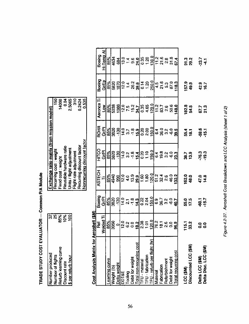
• . . _'v'#O,J • . . . . •
nm .
56
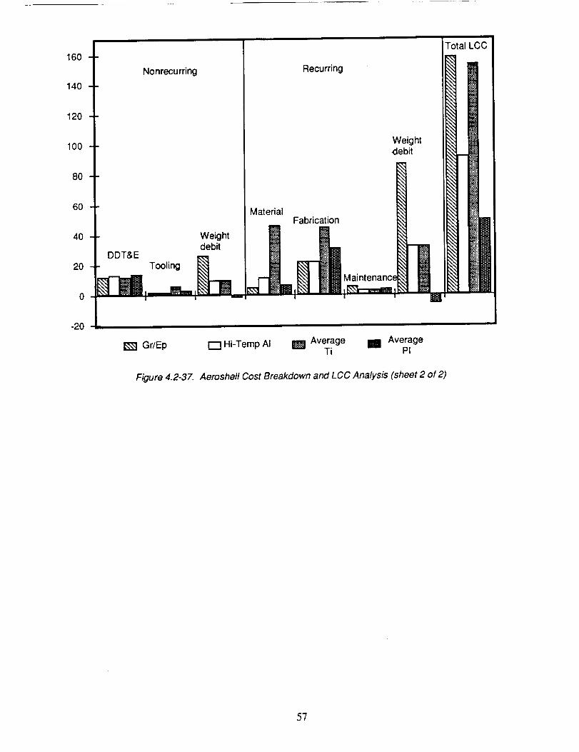
160
140
120
100
80
Nonrecurring Recurring
60 MaterialFabrication
4O Weight l
debitDDT&E
o i---"ll_ I _
Weightdebit
-2O
!I Ma'ntenanciml_ I
Total LCC
i'
Gr/Ep I--IHi-Temp AI I_ Average i AverageTi PI
Figure 4.2-37. Aeroshell Cost Breakdown and LCC Analysis (sheet 2 of 2)
57
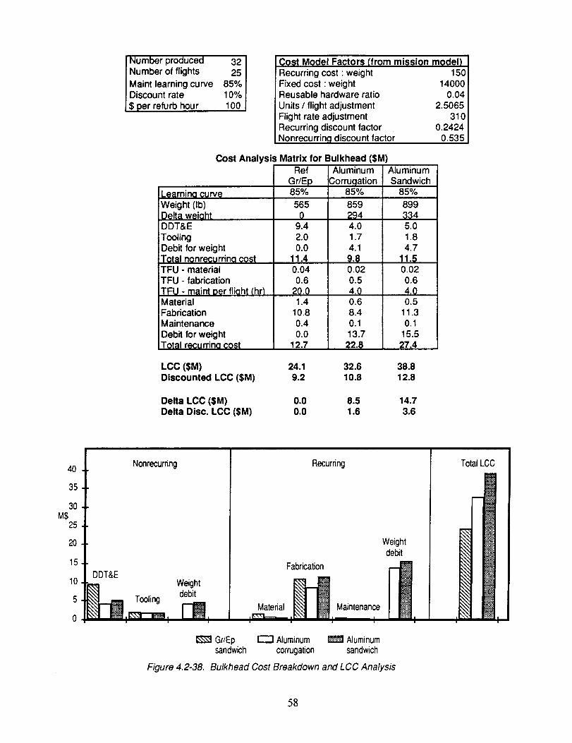
r Number produced 32Number of flights 25Maint learning curve 85%Discount rate 10%$ per refurb hour 100
Cost Model Factors (from mission modelRecurring cost : weightFixed cost •weightReusable hardware ratioUnits / flight adjustmentFlight rate adjustmentRecurring discount factorNonrecurring discount factor
15014000
0.042.5065
3100.2424
0.535
Cost Analysis Matrix for Bulkhead ($M)
Learnina curveWeight (Ib)Delta w_iahtDDT&EToolingDebit for weightTotal nonrecurrina costTFU - materialTFU - fabricationTFU - maint oer fliaht (hr_MaterialFabricationMaintenanceDebit for weightTotal recurrina cost
Ref
Gr/Ep85%
5650
9.42.00.0
11.40.040.6
2001.4
10.80.40.0
12.7
Aluminum
Corrugation85%
8592944.01.74.19.80.020.54.00.68.40.113.7
22.8
AluminumSandwich
85%
8993345.01.84.7
11.50.020.64.00.5
11.30.1
15.527.4
LCC ($M) 24.1 32.6 38.8Discounted LCC ($M) 9.2 10.8 12.8
Delta LCC ($M) 0.0 8.5 14.7Delta Disc. LCC ($M) 0.0 1.6 3.6
40
35
30MS
25
20
15
10
5
0
Nonrecurring
DDT&E
debit_ Tooling Weight
Recurring
Materiali __-m-_
Weightdebit
Fabrication Maintenance
I I I I
Gr/Ep I---I Aluminum _ Aluminumsandwich corrugation sandwich
Figure 4.2-38. Bulkhead Cost Breakdown and LCC Analysis
TotalLCC
I I
58
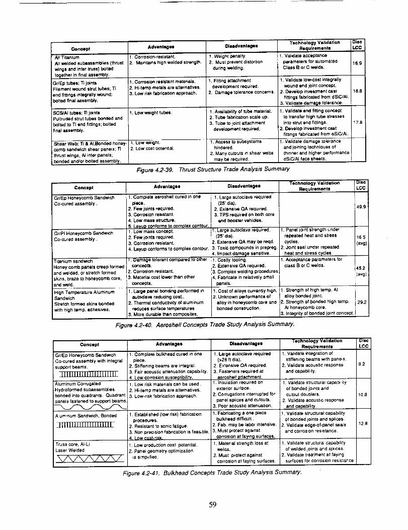
Concept Advantagell Diladvantlges Technology ValidationRequirements
All Titanium
All welded subassemblies (thrust
wings and inter truss) bolted
together in final assembly.
Gr/Ep tubes; "1'ijointsFilament wound sb'ut tubes; Ti
end fittings integrally wound;
bolted final assembly.
SCS/Al tubes: "13jointsPultruded strut tubes bonded and
bolted to Ti end fittings; boltedfinal assembly,
Shear Web; Ti & AI,Bonded honey-
comb sandwich shear panels; Ti
thrust wings, Al inter panels;
bonded and/or bolted assembly.
1. Corrosion-resistant.
2. Maintains high welded strength.
1. Corrosion resistant materials.
2. Hi-tamp metals are alternatives.3. Low risk fabrm.ation approach.
1. Low weight tubes.
1. Low weight.
2. Low cost potential.
1. Weight penalty.2. Must prevent distortion
during welding.
I. Rtting attachment
development required.
2. Damage tolerance concerns.
1. Availability of tube material.2. Tube fabrication scale up,
3. Tube to joint attachment
devalopment reduired.
1. Access to subsystemshindered,
2. Many cutouts in shear webs
may be required,
1. Validate acceptance
parameters for automatedClass B or C welds.
I. Validate low-cost integrally
wound end joint concept.
2. Develop investment castfittings fabricated from dSiC/Al.
3. Validate damage tolerance•
I.Validate end fitting conceptto transfer high tube stresses
into strut end fittings.
2. Develop investment ca_tfittings fabricated from dSiC/Al.
1. Validate damage tolerance
and joining techniques of
thinner and higher performancedSiC/AI face sheets•
DiaoLCC
16.9
18.8
17.8
Figure 4.2-39. Thrust Structure Trade Analysis Summary
Concept Advantages Disadvantages
Gr/Ep Honeycomb Sandwich
Co-cured assembly.
Gr/PI Honeycomb Sandwich
Co-cured assembly.
Titanium sandwich
Honey comb panels creep formedand welded, or stretch formed
skins, braze to honeycomb core,and weld.
High Temperature AluminumSandwich
Stretch formed skins bonded
with high temp. adhesives.
1. Complete aeroshall cured in one
piece.
2. Few joints required.3. Corrosion resistant,
4. Low mass structure.
5. Layup conforms to complex contour.1. Low mass concept.
2, Few joints required.3. Corrosion resistant.
4. Layup conforms to complex contour•
11. Damage tolerant compared to other
concepts.2. Corrosion resistant.
3. Material cost lower than other
concepts.
1. Large panel bonding performed in
autoclave reducing cost.,2. Thermal conductivity of aluminum
reduces surface temperatures3. More durable than composites.
I.Large autoclave required
(25' dia).
2. Extensive QA required.
3. TPS required on both coreand booster vehicles.
I. Large autoclave required.
(25' dia).2, Extensive QA may be reqd.
3, Toxic compounds in prepreg.
4, Impact damage sensitive.
1. Costly tooling.
2. Extensive QA required.
3. Complex welding procedures4. Fabricate in relatively smal_
panels.
1, Cost of alloys currently high.2, Unknown performance of
alloy in honeycomb core andbonded construction.
Technology ValidationRequirements
1. Panel joint strength under
repeated heat and stress
cycles.2. Joint seal under repeated
heat and sVess cycles.
• Acceptance parameters forclass B or C welds.
:1. Strength of high temp. AI
alloy bonded joint.
2. Strength of bonded high tamp•AI honeycomb core.
3. Integrity of bonded joint concept.
Disc
LCC
4g,9
16.5
(avg)
45,2
(avg)
29,2
Figure 4.2-40. Aeroshell Concepts Trade Study Ana/ysis Summary.
Concept
Gr/Ep Honeycomb Sandwich
! Co-cured assembly with integral
support beams.
Aluminum Corrugated
Hydroformed subassembliesbonded into quadrants, Quadrant
)anels fastened to support beams.
Aluminum Sandwich, Bonded
Truss core, AI-Li
Laser Welded
Advantagea
I. Complete bulkhead cured in one
piece.
2. Stiffening beams are integral.3. Fair acoustic attenuation capability.
4. Low corrosion susceptibifi_y.
1. Low risk materials can be used,
2. Hi-tamp metals are alternatives,3. Low-risk fabrication approach.
I.Established (low risk)fabrication
procedures,
2. Resistant to sonic fatigue.3. Non precision fabrication is feasible.4. Low cost-risk.
1. Low production cost potential.
2. Panel geometry optimizationis simplified.
DIMdvanlagaa
I,Large autoclave required(>26 ft dia).
2. Extensive QA required,
3. Fasteners required ataerosheit attachment.
1. Insulation required onexterior surface.
2. Corrugations interrupted forpanel splices and cutouts.
3. Poor acoustic attenuation.
1. Fabricating a one piece
bulkhead difficult.
2. Fab. may be labor intensive.3. Must protect against
corrosion at fa),ing surfaces.
1. Material strength loss atwelds.
2. Must protect against
corrosion at faying surfaces.
Technology Validation
Requirements
1. Validate integration of
stiffening beams w_th _nels.2. Validate acoustic response
and capability,
1. Validate structural capability
of bonded joints andcutout doublers•
2. Validate acoustic response
and capability.
1. Validate structural capability
of bonded joints and splices.
2. Validate edge-of-panel sealsand corrosion resistance.
'1. Validate structural capability
of welded joints and sluices.2. Validate treatment at laying
surfaces for corrosion resistance.
DiscLCC
9.2
10.8
12.8
Figure 4.2-41. Bulkhead Concepts Trade Study Analysis Summary.
59
The cost differences between the aeroshell concepts are more significant as shown in figure 4.2-40.
The Ti sandwich concept primary cost driver is fabricating the panel subassemblies. The Ti sandwich
face sheets must be hot formed, and this drives up the cost of both tooling and processing. Vacuum
furnaces for diffusion bonding or brazing core to face sheets limits panel size. In the large aeroshell,
many panels are required in a variety of contours. Maintaining fit-up tolerance for welding so many
panels is also costly. The Gr/PI sandwich concept has the lowest discounted LCC, however the costing
procedures used cannot fully account for the high risks associated with fabricating this type of material,
and with impact damage durability during operation.
A potentially low-risk option is to fabricate a one piece Gr/Ep sandwich aeroshell and use a TPS to
protect the booster as well as the core. However, the increased weight and per flight maintenance of the
TPS required for booster module trajectory reentry increases the LCC over the Gr/PI concepts.
The bonded HTA aeroshell concept combines the positive features of both the metallic and
composite concepts. Large panel segments, including the dome, can be co-bonded in existing autoclaves
reducing the amount of joining required. The metal face sheets, although bonded, should diminish the
damage tolerance concerns of the composite concepts. Given an appreciation for the uncertainties in cost
estimating, the HTA aeroshell may provide a low cost alternative to the Ti concepts, and a more robust
alternative to the Gr/Ep and Gr/PI concepts. The uncertainties in applying HTAs to integrated, large
structure requires that the HTA concept be validated in continuing research and development. In
particular the performance of HTA face sheets bonded to honeycomb core requires investigating. Joints
are also critical on the aeroshell from cost and performance perspectives.
Weight differences are most significant for the bulkhead concepts as shown in figure 4.2-41. The
corrugated aluminum concept was proposed as potentially the low-cost option, but is penalized by high
weight. The bonded aluminum sandwich concept was unexpectedly heavy due to minimum gage
limitations. Upon reflection, we feel a Gr/Ep truss core bulkhead is potentially a structurally efficient
concept for the bulkhead, and should be considered in future trade studies.
In summary, the aeroshell exceeds both the thrust structure and aft bulkhead in overall LCC impact.
This is due to its large weight, cost of tooling, and complex fabrication involving such details as access
doors and compound contours. Additional development effort would find the largest payoff if
concentrated on the aeroshell structure.
60
4.3 TASK 3: TECHNOLOGY DEVELOPMENT PLAN
The aeroshell structural concept selected for further development employs HTA alloys and
composites. Honeycomb panel construction provides stiffness against water impact (splash-down). For
cost effectiveness the honeycomb swucture will be bonded. Four candidate adherend alloys for the face
sheets are included below.
CandidateAlloy8009WeldaliteSiCp/8009
SiCp/8090
AdvantageHigh-temperatureAI alloyAI-Lialloywithhigh-temperaturecapabilityReinforcementincreasesstrengthandstiffnessandmay increasetemperaturecapabilityReinforcementincreasesstrengthandstiffnessandmay increasetemperaturecapability
Supplier
Allied-SignalReynoldsAllied-Signal
DWA
Candidate adhesives have been selected to correspond with the temperature capability of the face
sheet materials. EA 9674, supplied by Hysol, is a modified bismaleimide film adhesive with structural
capability up to 550°F. FM 680 is a well established polyimide adhesive. The PT Resin is an adhesive
under development at Allied-Signal. It is a modified phenolic system developed for use in high
temperature and high performance applications. Curing is through a total addition reaction, eliminating
the generation of volatiles. AF- 191 cures at 350°F and is supplied by 3M. It is included for use with the
materials that would anneal at the high bonding temperatures required by the other adhesives.
4.3.1 Phase Ih Technology Validation
This phase develops the technologies required for successful reusable structures demonstration. A
down selection of materials and structural concepts shall be made so that a specific reusable concept can
he demonstrated in Phase III.
Task 1: Lao Shear Testing. The first portion of the Phase II test program is to screen candidate
adhesives. Lap shear testing will verify the preparation and bonding processes using these advanced
adherends and adhesives. Figure 4.3-1 shows the test matrix. Testing will be performed over the
temperature range consistent with the material capabilities. The three high temperature adhesives will
be fully assessed with 8009 alloy adherends across the representative temperature range. Verification
of adhesive capability will be made with the SiCp/8009 material in the high temperature regime.
61
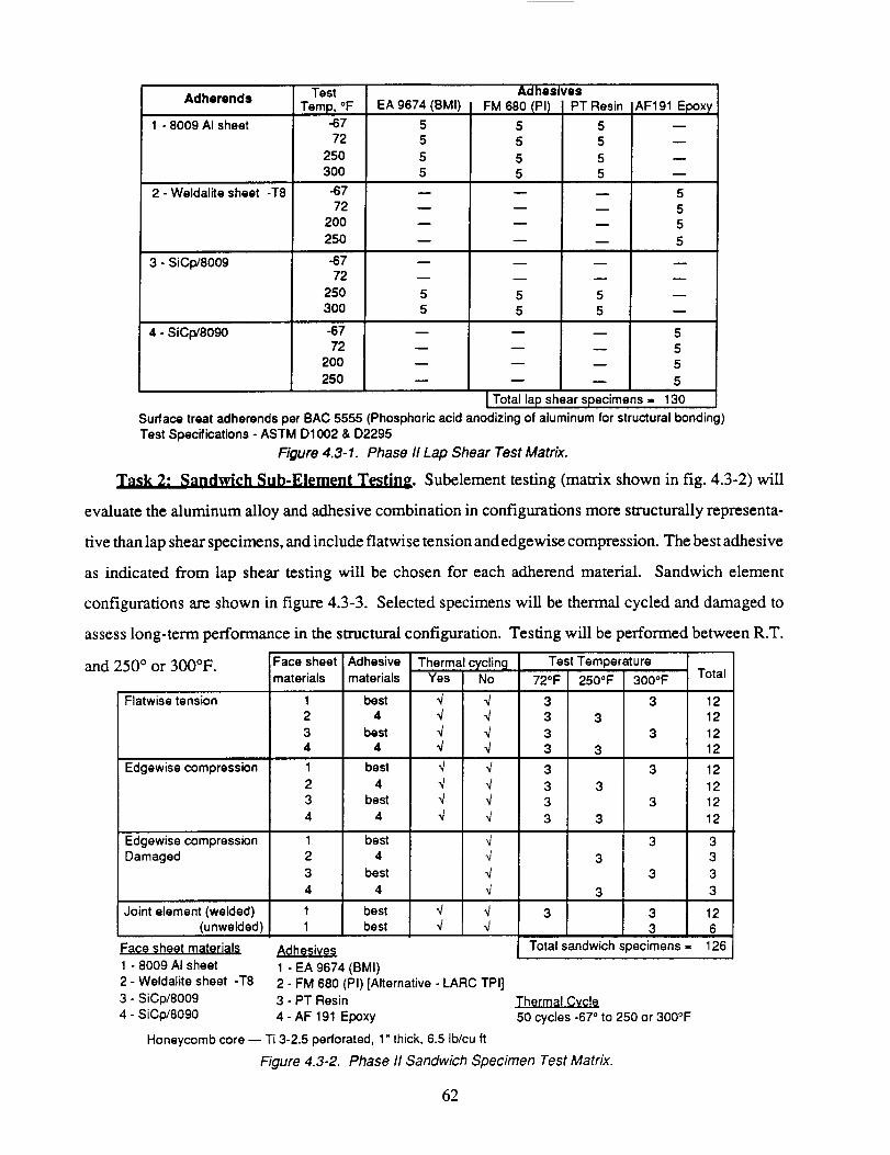
Adhemnds
1 - 8009 AI sheet
2 - Weldalite sheet -T8
3 - SiCp/8009
4 - SiCp/8090
Test
Temp, oF-6772
250
30O
-67
72
200
250
-6772
250
300
-67
72
2OO
25O
EA 9674 (BMI) ]
55
5
5
m
I
5
5
D
Adhesives
FM 680 IPI)
55
5
5
D
m
5
5
m
m
I PT Resin
m
g
E
m
m
55
m
IAF191 Epoxy
m
55
5
5
Total la shears ecimens = 130
Surface treat adherends per BAC 5555 (Phosphoric acid anodizing of aluminum for structural bonding)
Test Specifications - ASTM D1002 & D2295
Figure 4.3-1. Phase/I Lap Shear Test Matrix.
Task 2: Sandwich Sub-Element Testing. Subelement testing (matrix shown in fig. 4.3-2) will
evaluate the aluminum alloy and adhesive combination in configurations more structurally representa-
tive than lap shear specimens, and include flatwise tension and edgewise compression. The best adhesive
as indicated from lap shear testing will be chosen for each adherend material. Sandwich element
configurations are shown in figure 4.3-3. Selected specimens will be thermal cycled and damaged to
assess long-term performance in the structural configuration. Testing will be performed between R.T.
and 250 ° or 300°F.
Flatwise tension
Edgewise compression
Edgewise compression
Damaged
Face sheet
materials
1
2
3
4
Adhesive
materials
bed
4
best
4
best
4
best
4
best
4
best
4
Joint element (welded) 1 best
(unwelded) 1 best
Face sheet materials
1 - 8009 AI sheetAdhesives
1 - EA 9674 (BMI)
Thermal cyclingYes No
q qq qq qq qq qq qq qq q
,J
2 - Weldalite sheet -T8 2 - FM 680 (PI) [Alternative - I_ARC TPI]
3 - SiCp/8009 3 - PT Resin
4 - SiCp/8090 4 - AF 191 Epoxy
Honeycomb core n Ti 3-2.5 perforated, 1" thick, 6.5 Ib/cu ft
Test Temperat u re
72OF 250OF 300OF
3
3 3
3
3 3
3
3 3
3
3 3
3
3
Total
3 12
12
3 12
12
3 12
12
3 12
12
3 3
3
3 3
3
3 12
3 6
126Total sandwich specimens =
Thermal Cycle
50 cycles -67 ° to 250 or 300°F
Figure 4.3-2. Phase II Sandwich Specimen Test Matrix.
62
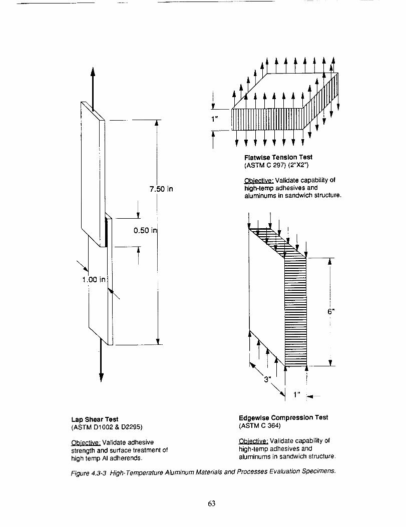
1.00 in
[,[
7.50 in
0.50 in
t
N
fttttt_
rrIIIrlrrl,rlFlatwlse Tension Test(ASTM C 297) (2"X2")
Validate capability ofhigh-temp adhesives andaluminums in sandwich structure.
A
_
Lap Shear Test(ASTM D1002 & D2295)
Edgewise Compression Test(ASTM C 364)
Ob!ective: Validate adhesivestrength and surface treatment ofhigh temp AI adherends.
Ob!_ctive; Validate capability ofhigh-temp adhesives andaluminums in sandwich structure.
Figure 4.3-3 High-Temperature Aluminum Materials and Processes Evaluation Specimens.
63
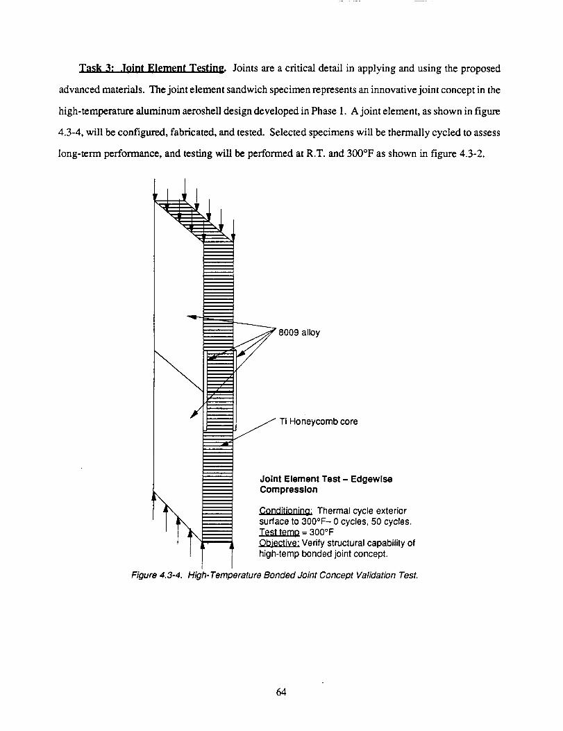
Task 3: Joint Element Testinm Joints are a critical detail in applying and using the proposed
advanced materials. The joint element sandwich specimen represents an innovative joint concept in the
high-temperature aluminum aeroshell design developed in Phase 1. A joint element, as shown in figure
4.3-4, will be configured, fabricated, and tested. Selected specimens will be thermally cycled to assess
long-term performance, and testing will be performed at R.T. and 300°F as shown in figure 4.3-2.
8009 alloy
Ti Honeycomb core
Figure 4.3-4.
Joint Element Test - EdgewiseCompression
Conditioning: Thermal cycle exteriorsurface to 300°F - 0 cycles, 50 cycles.
= 300OFObjective: Verify structural capability ofhigh-temp bonded joint concept.
High- Temperature Bonded Joint Concept Validation Test.
64
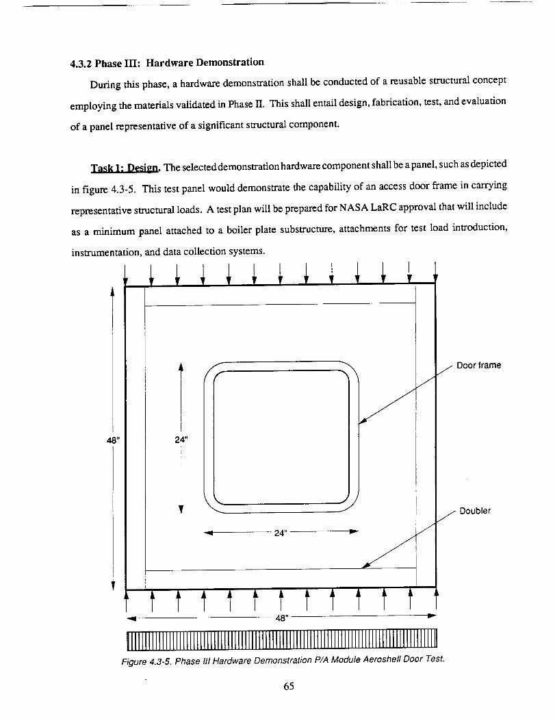
4.3.2 Phase IIl: Hardware Demonstration
During this phase, a hardware demonstration shall be conducted of a reusable structural concept
employing the materials validated in Phase II. This shall entail design, fabrication, test, and evaluation
of a panel representative of a significant structural component.
_. The selected demonstration hardware component shall be a panel, such as depicted
in figure 4.3-5. This test panel would demonstrate the capability of an access door frame in carrying
representative structural loads. A test plan will be prepared for NASA LaRC approval that will include
as a minimum panel attached to a boiler plate substructure, attachments for test load introduction,
instrumentation, and data collection systems.
48"
,_L__L:
24"
,J
J
"q 24"
\ j Door frame
j Doubler
-- 48" v
!1111111111111111111111111111111111111IIIlllllllllIII1111III1II11111111111IlllllIIIIFigure 4.3-5. Phase III Hardware Demonstration P/A Module Aeroshell Door Test.
65
Task 2 - Fabrication. A fabrication plan will be prepared for NASA LaRC approval that shall
include as a minimum detail drawings, material requirements, tool designs, asscmbly techniques, and
quality assurance provisions. Upon approval from NASA LaRC, demonstration panel detail parts will
be fabricated and assembled.
Task 3 - Testing and Evaluation. The approved NASA LaRC plan will be executed for testing the
demonstration panel. Data will be obtained to validate and possibly ref'me earlier structural models and
analyses. The test data will be evaluated to assess the applicability of the advanced technologies studied
here to future reusable structures. Following test and evaluation, the tested panel will be delivered to
NASA LaRC.
Schedule:
The schedule for Phase II is shown in figure 4.3-6. Phase II is expected to require approximately
10 months to complete.
66
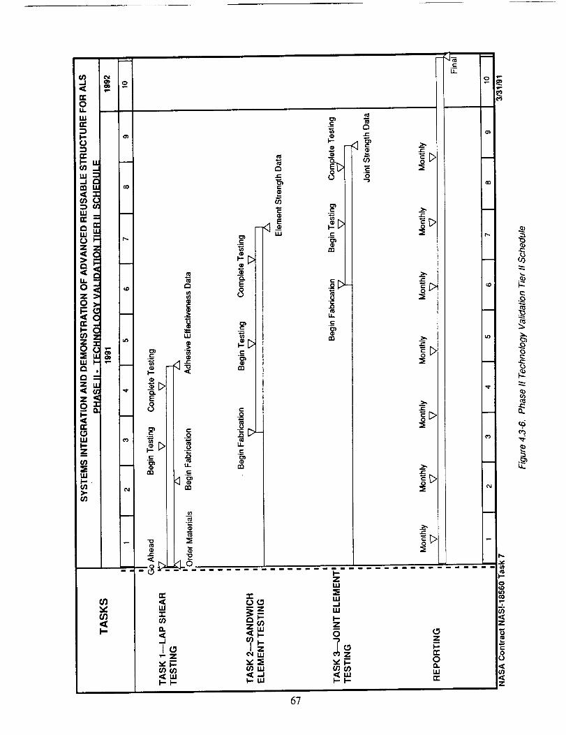
v_
u.
5 =C:w o_
_ °_
a:_ "_
_. ,- ®
0. 8-
z _>
_ U-
W co .c
>.. c_6_
_C
,<F-
.=.-
-8
re"
I.U"T"
O..<
"Z
._LU
o_._c
E
8
._c
_n
.o
_>-U.
.c
C_
C_
UJ
"r.
.c_O1C__0
.13
U.
._c
_n
r_t-
09
O
>,
_>
t--
_>
>,
_>
r-
_>
c-
_>
=O(O
_zc_r-Zuj
oaLij
_uJ
h-ZuJ
uJ..Jw
Z
O
Z"{F-_(S)
I-I-
67
U.
0_zI-n-OO.WIT
m
0
co
-C::
o
z
8

This page intentionally left blank
68
5.0 CONCLUSIONS
Preliminary requirements, loads, and environments are defined for reusable structure on the ALS
P/A module.
Design concepts and candidate materials are defined for P/A module structure (thrust structure, aft
bulkhead, and aeroshell) that conforms to the preliminary requirements, and these concepts are available
for further specification and development. Stress analysis indicates that all structural concepts analyzed
can perform to the identified loading conditions.
The baseline thrust structure truss configuration using Gr/Ep, Ti, or SCS/A1 tube members is
feasible. LCCs are virtually indistinguishable among these concepts. Time limitations prevented full
consideration of shear web thrust structure, which may have cost benefits in the highly loaded areas.
Several bulkhead concepts and material applications are available for further development. Cost
analysis indicates that lower structural weight provides the Gr/Ep sandwich concept a lower LCC than
the A1 corrugation or the A1 sandwich concepts.
Thermal analysis indicates that mature aeroshell structural materials must be protected (with a TPS)
from the temperatures experienced by the core P/A module when reentering the atmosphere upon return
from orbit.
The aeroshell has the highest LCC impact of the three structural elements studied, and is dominated
by fabrication cost. Therefore, further efforts should concentrate on developing the aeroshell structural
elements to offset high-cost features.
The Ti aeroshell LCC is driven by the requirement to hot form or creep form the compound
curvatures, and to braze many sandwich structural panels of limited size.
The HTA aeroshell combines the durability of metallic structure with bonded construction
permitting large panel fabrication in existing autoclaves. HTA alloys and fabrication methods are less
mature than those for Ti and Gr/PI, therefore Phase II of this contract should concentrate on developing
HTA technology.
69PRECEDING PAGE BLANK NOT FILMED
6.0 REFERENCES
.
*
.
.
5.
.
.
"Definition of Propulsion/Avionics Module for Advanced Launch Vehicles," Final Report,Contract NAS8-36623, Marshall Space Flight Center, DPD-669, February 1988.
M. N. Gibbins, "Reusable Structure for the Advanced Launch System," IAF-90-180, 41 st Inter-
national Astronautical Congress, October 1990.
B. Erb, et. al., "Apollo Thermal-Protection System Development," Journal of Spacecraft andRockets, Vol. 7, No. 6, June 1970.
ASTECH Design Manual ADM-300, TRE Corporation, April 1977.
J. Anderson, et. al., "Development of Reusable Metallic Thermal Protection System Panels forEntry Vehicles," NASA CR 181783, August 1989.
W. Blair, et. al., "Fabrication of Prepackaged SuperaUoy Honeycomb Thermal Protection System(TPS) Panels," NASA CR 3755, October 1985.
R.D. Vannucci and D. Cifani, "700°F Properties of Autoclave Cured PMR-II Composites,"NASA TM 100923, September 1988.
7O
APPENDIX A - DESIGN DATABASE
1 Structural Materials 72
These charts list the properties for the structural materials we used in performing our trade studies,
design concept preparation, and analyses. A-basis allowables were used when possible. Reduced vendor
or typical properties were used otherwise.
2 Thermal Protection System Materials 76
These charts show our survey of feasible TPS materials for application to the aeroshell ablator.
We feel that reliable data for key ablative properties such as maximum heat flux capability are currently
unavailable, and testing is required for further TPS concept definition, performance analysis, and concept
optimization.
71
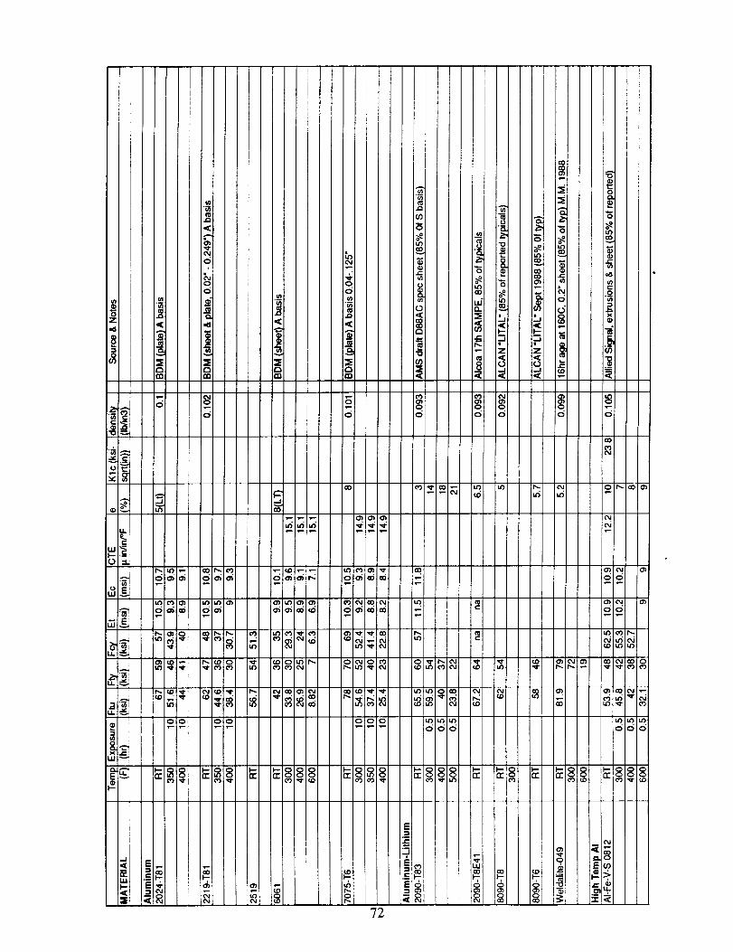
72
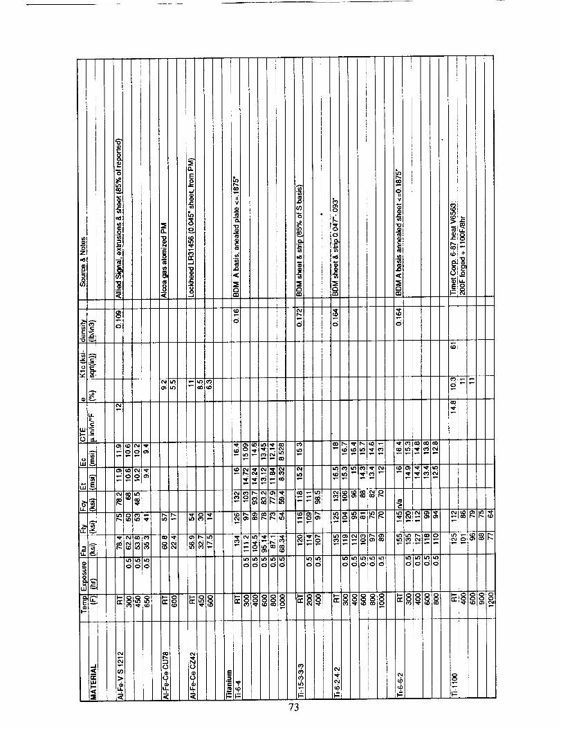
73
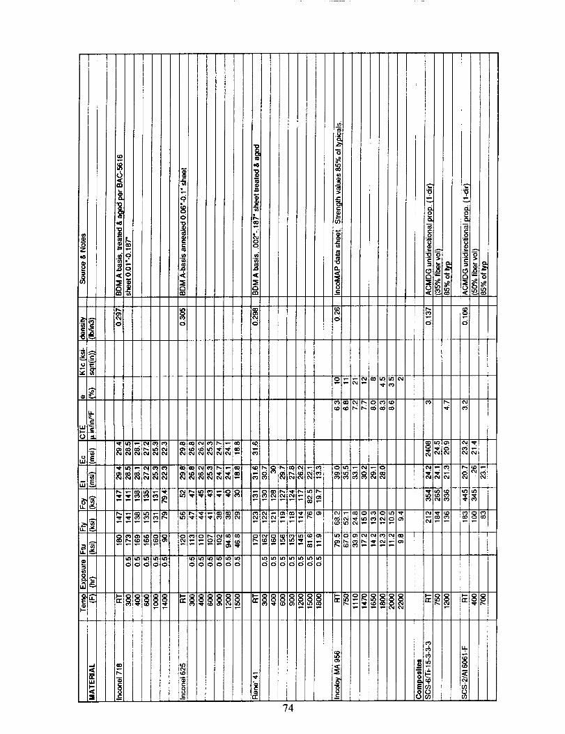
74
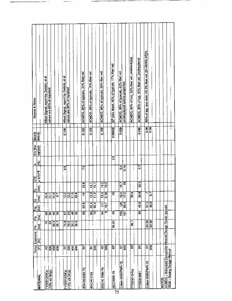
o
c5
iI
_ ,
i i
Ii
_ __
_- c'E
.D CO O)
0
75
D
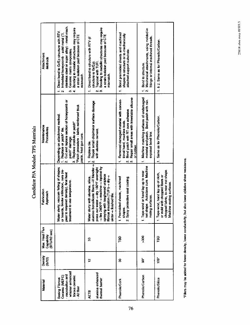
o_
ell
°_-,i
ell
C
e-
X
":_----4=
_'o
iS_e_ _ __•-;_ e4#
e,i .._
_. i_i
'=" >,O
o i_..; _
Ncu_No _- _.N
•-; o,ie6
&
.C ..a
"88
•_.-._ [= .--
_----_. _ll_-
.--r
__ ' _-.__.__
_i • _ '-"- 8' t
c_
i%1
ill
"8>,
_o_Oe-i
8.8
® _"0 e-' I,-- .
_:.o_,,- o,-: N_
I--
o
0
e-
._c
EE
o__ _
• _
•.: e,i ,-;
_'e
oO.
_.8 _
__ _
^ F-
el
0 0
.,_ e-I_. 0.
0
8
.__el
L_
t"-_
76
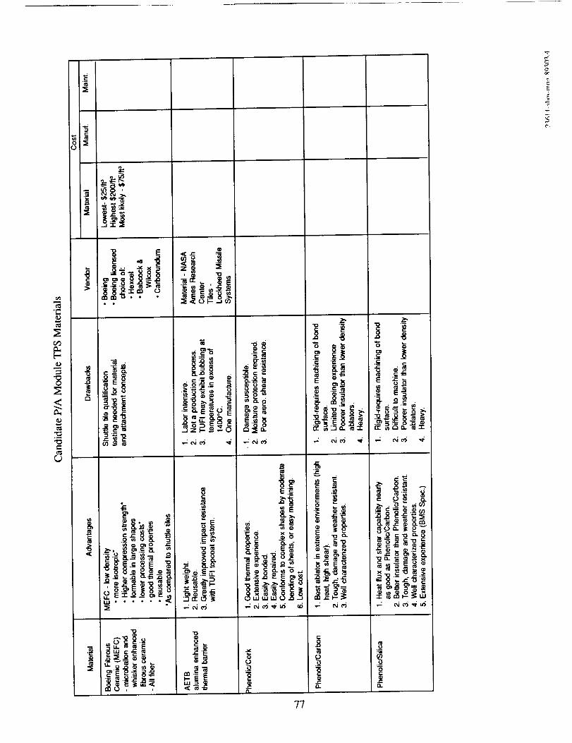
cD
4.;,c
,..z
J
• •
._® _o.
u. Ei_O_o _
_<_-
._ e'_ _ __x_ ,_
C
800.
_=_-
"0
LU
_m
°°_._ ..
_,_ o.,_'_0
r.,_LU UJ LIJ L)
cJ
_0
-E"_
_o
_ N
_S_
"6
E -5_
._ _-_
_, ._."_
_R _-'_._
_. _ oo._
"OQ._ _x
"I" _ml _'_
0
O.
?7
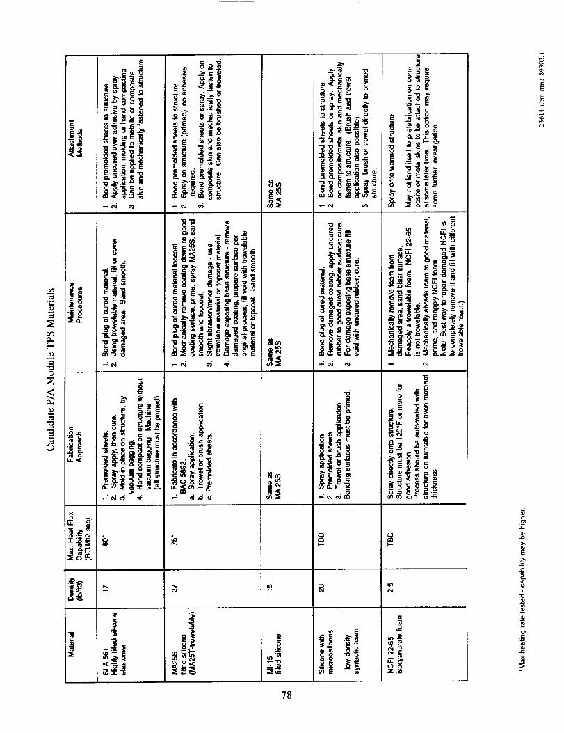
r.#l
-[=
¢I,,
.,...q
C
-B
¢
,_- ,
•".=I=._-..
8_
_A
¢II
IE
Ill _I-__, l'E-q
_ ,DEN
q) ,v
,_J.a ,q,. _1 '.,,J cn
•,:_ c6
..,_,
-.N E
;..a•
81
oj
e- o
! ""- -_
' • .I,_ •
•_ li__
8
,_._
A
8_
E
8
_-]__o_
_._ . ._
._-" ,,_
•_e,-,_i ,-__ 2_._
8_.__
Q
I--
,,-,1
_o
33_2
JF_,-_.--
._,_._._ e m' cN E'- u•.=-ccc._ :_ _.:_ .9.o
_,o •
,,_-_
_OGO
r-,
tn
c,,i
..9.o¢)
oZ._
78
J#,
0,.m
t-
OJ_
t_
E
.g
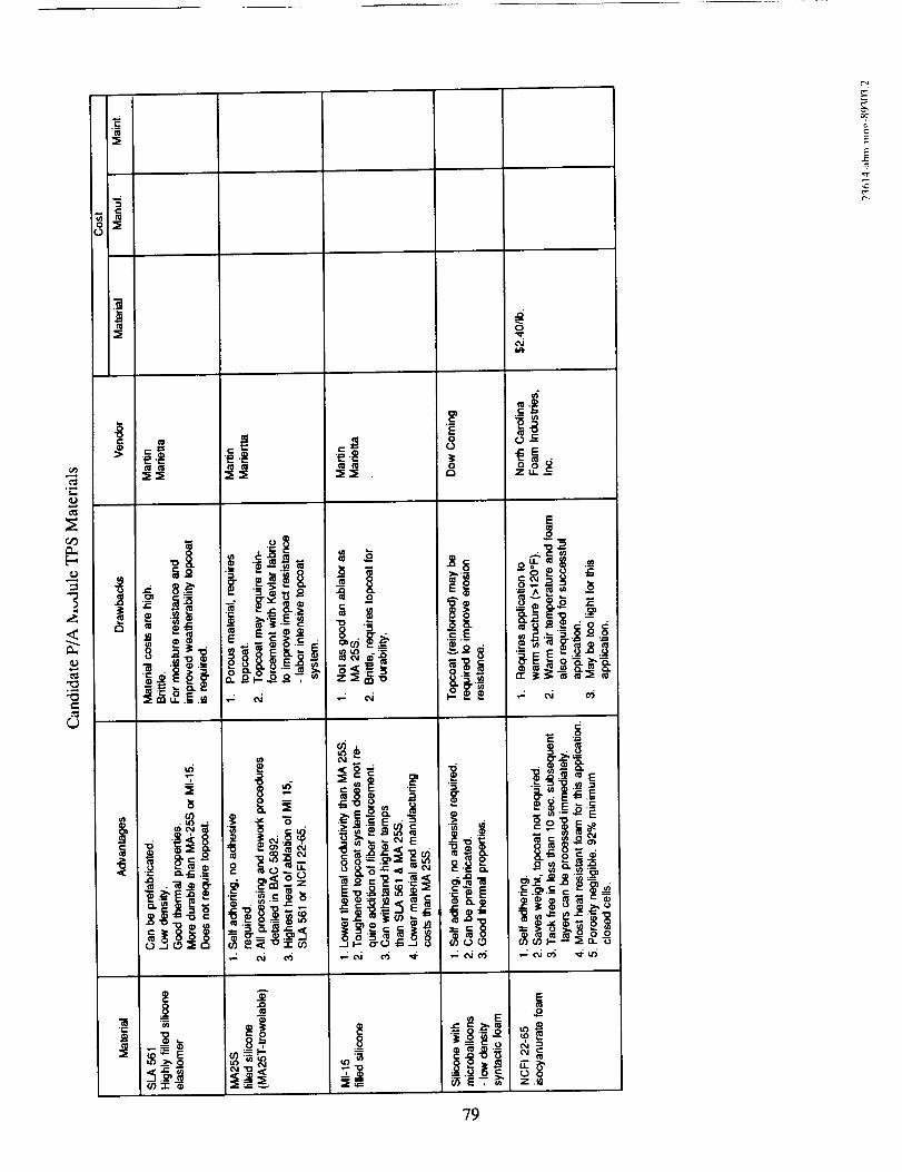
.c:E
:E
uY.._E._
:E
C
8
o _._-g'- _ _
._ -_ _
o c _.
Q'd _'--- '- 15
_ _- _ ._ _iu_
_ _ e6
_=_-
I
..: e,i
8
,I
E6o_
C_
u_ ._
E
.goTM ._
r-
(3" _--
O" ... E "_ .1_
E _._
(/) CO I-- -- _, _. "_
,.9
Z._
C.l
(_
79

This page intentionally left blank
80
APPENDIX B - STRUCTURAL DESIGN CONCEPTS
The following charts summarize the initial structural concept definitions for the truss, aeroshell, and
bulkhead. Summaries include: a) technical details - geometries and materials, that serve as a starting place
for concept comparison and development; b) advantages and drawbacks - preliminarily identified issues in
fabrication and performance; c) materials options - the various materials applicable to the concept; d)
fabrication approach - briefly described process for manufacturing the concept; and e) design features - the
features that set the concept apart.
1 Aeroshell 82
2 Thrust Structure 91
3 Bulkhead 98
81
PAGE L-'q.ANK NG_ f]:_MYD
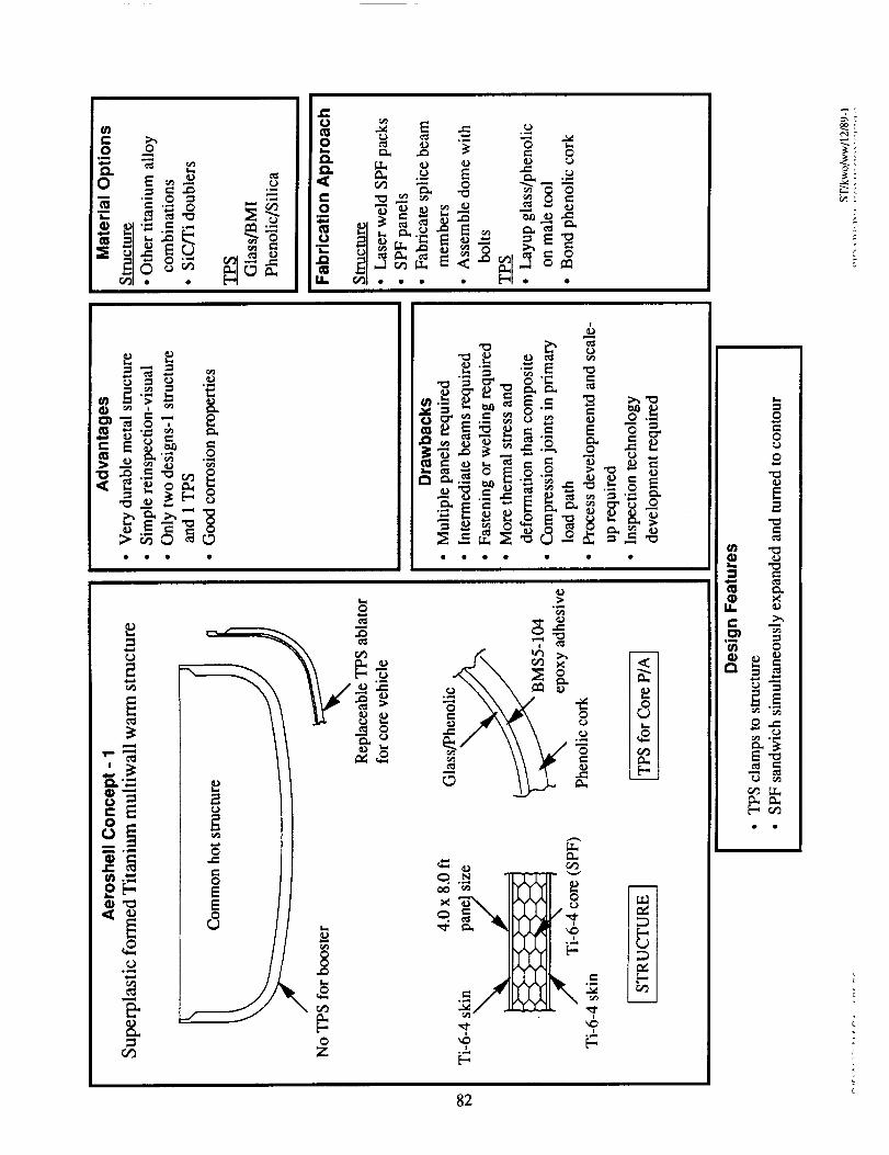
_
° _
"T,
1t2
i
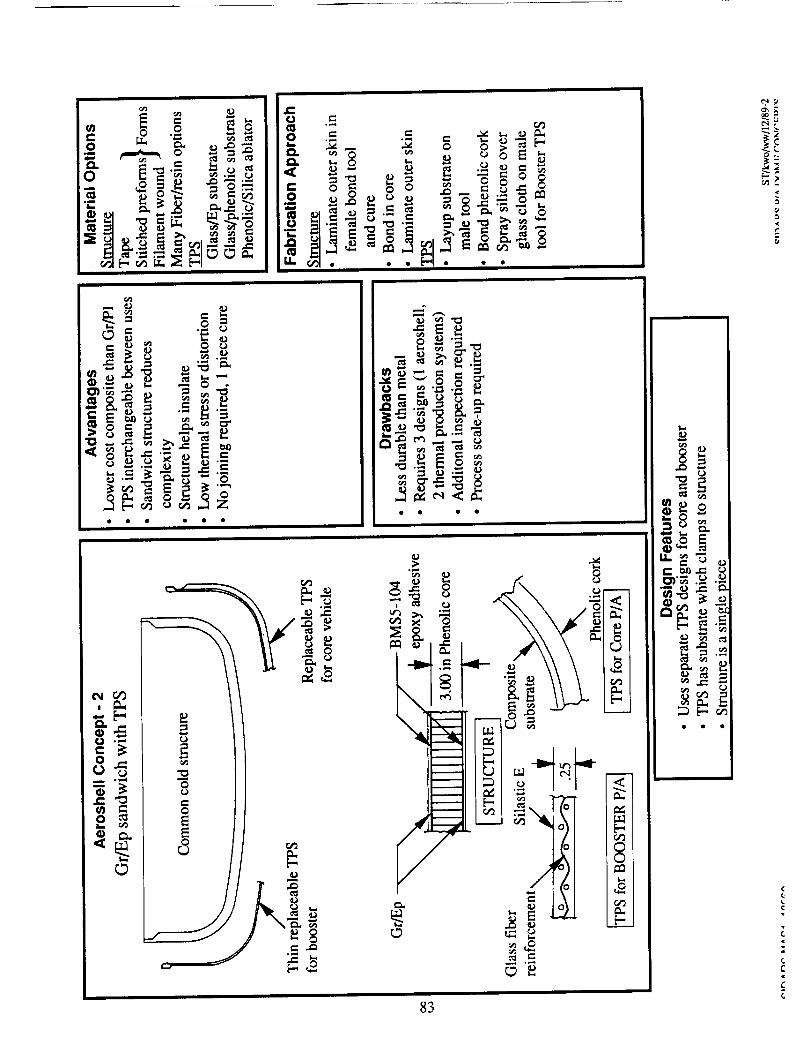
2
_-_ .._
e_
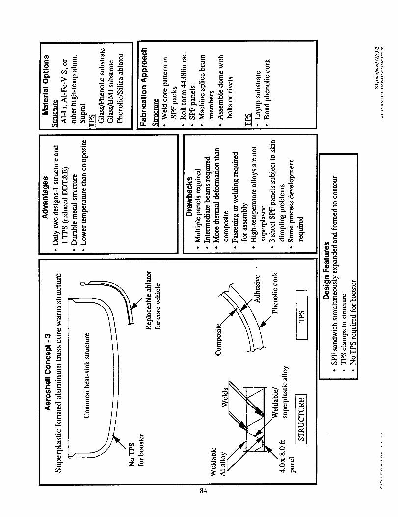
84
_r
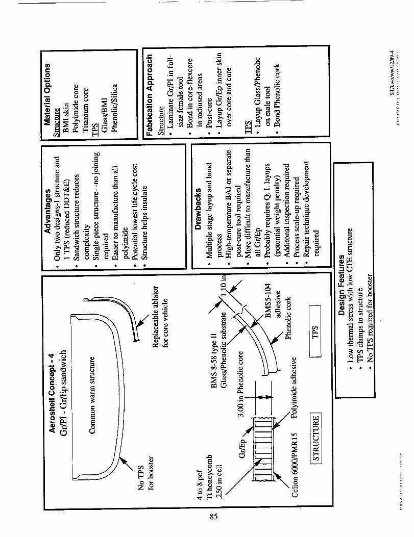
85
0 •
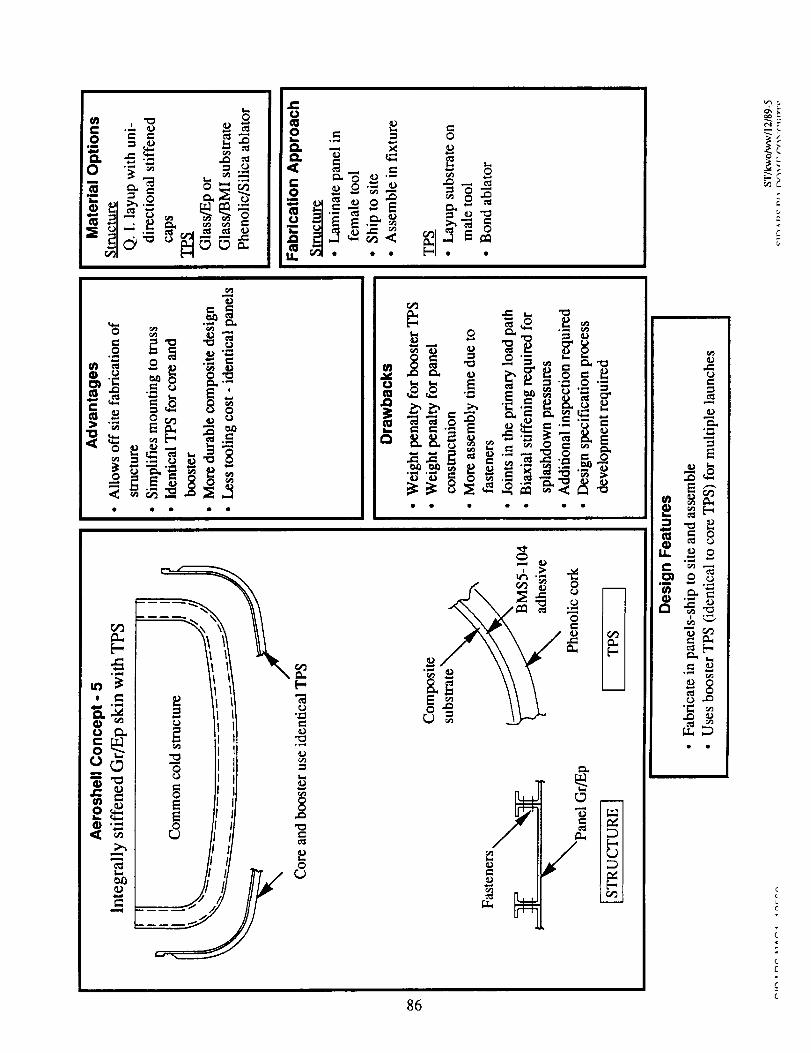
86
o_
_>
re,#
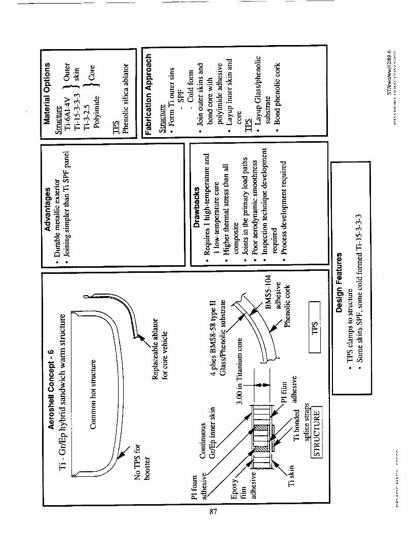
r,.)
,_,.=
c_I
E-,
8"/
,,- _=
•_, _ S
OCI.
_E_F-- >
cL
0 ,.
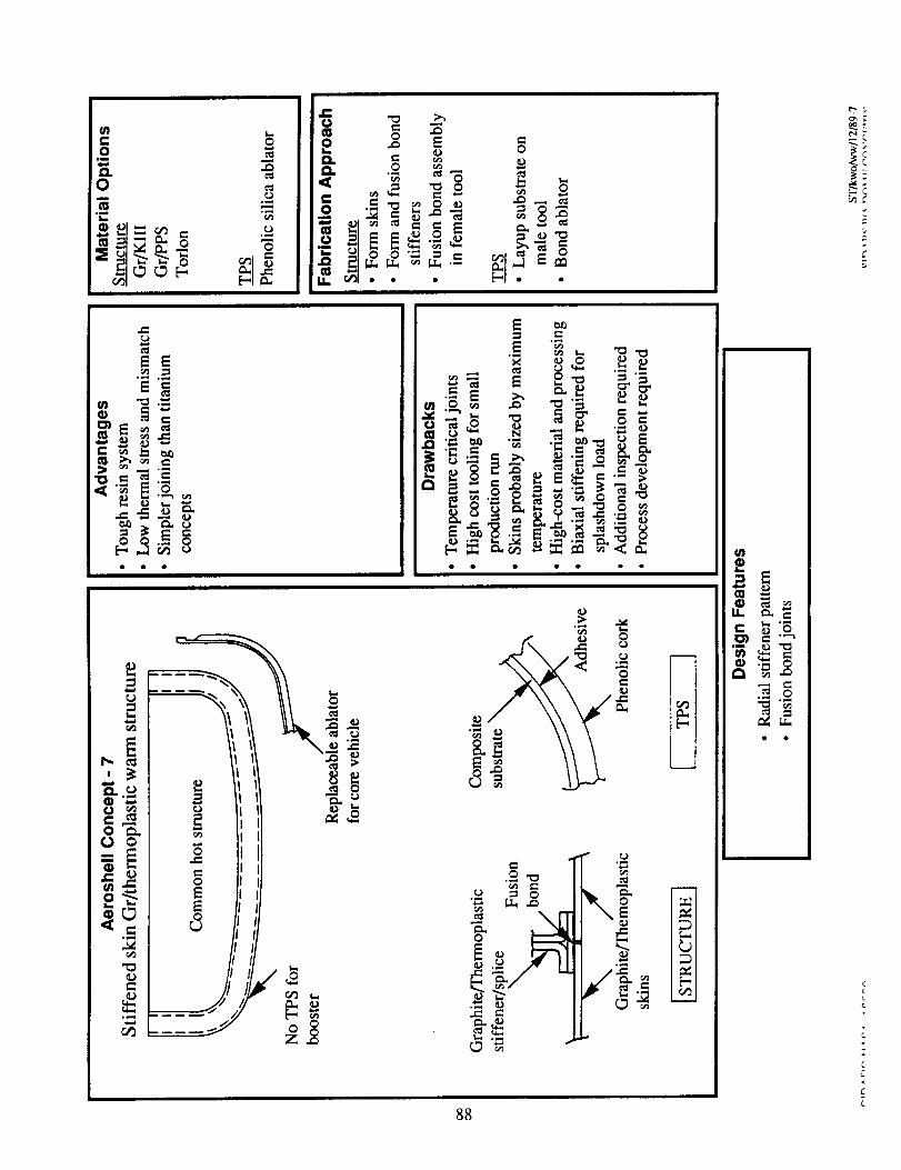
II
°_Z
88
ffl
,-, o
--L
C
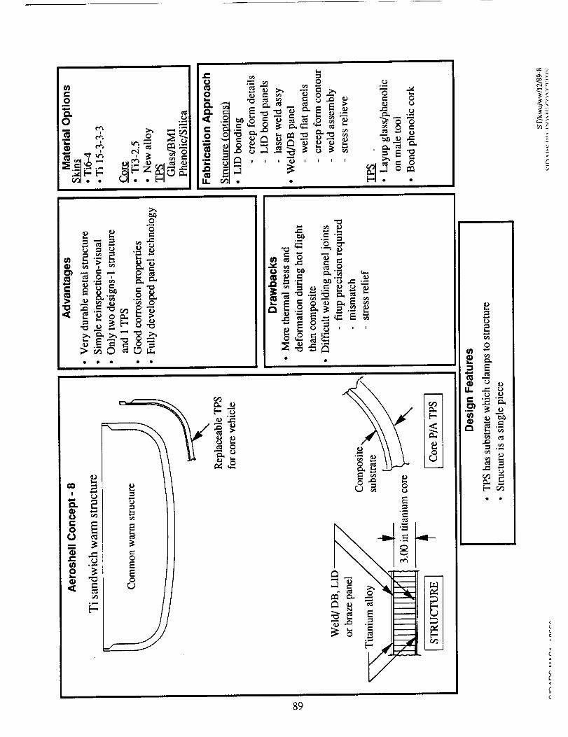
89
_'_
_._
;CL
Z
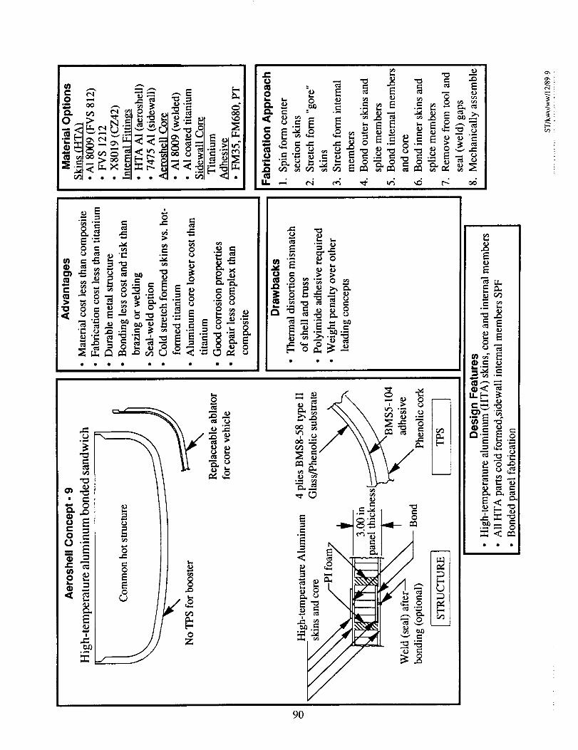
_ _ _
-" o ii-•_ _ -_ _ _ _ ._- _ _" L.= i
oooo oo • oo
0Z
.._ E __ °
.o _ "v, o
-_._ _ =
_ "
_ _._,
• ,'-. _ _
8_
._ ._:
u.[-
9O
o
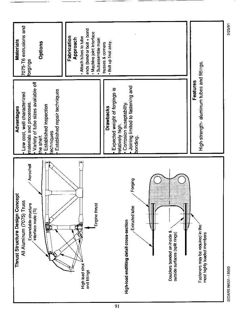
91
I,,¢')C,,,I
0
'T
_2Z
COrr"
0")
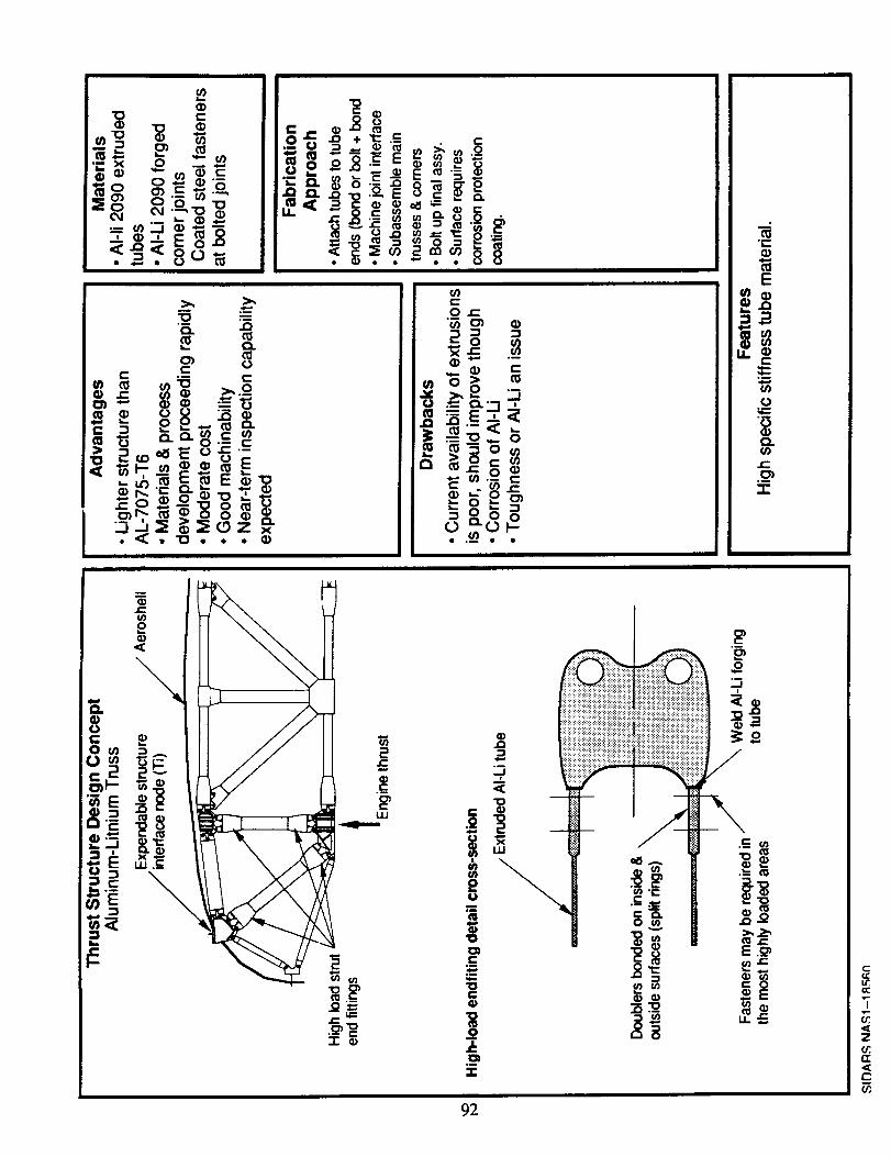
i
+(I)
,.,._::I::
92
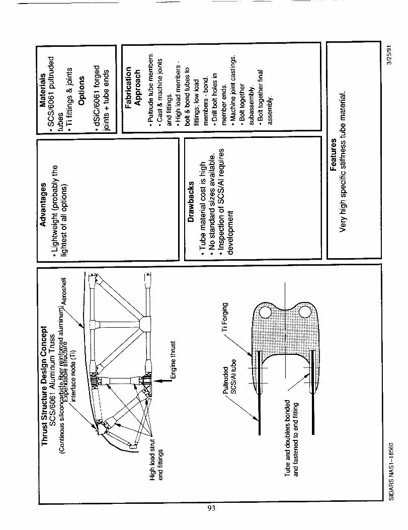
._s , 8,
_,_ _ +_ -_
,,+
+
0
0
0")o-
R"
CO
0_0
cO
"7
7
rr
93
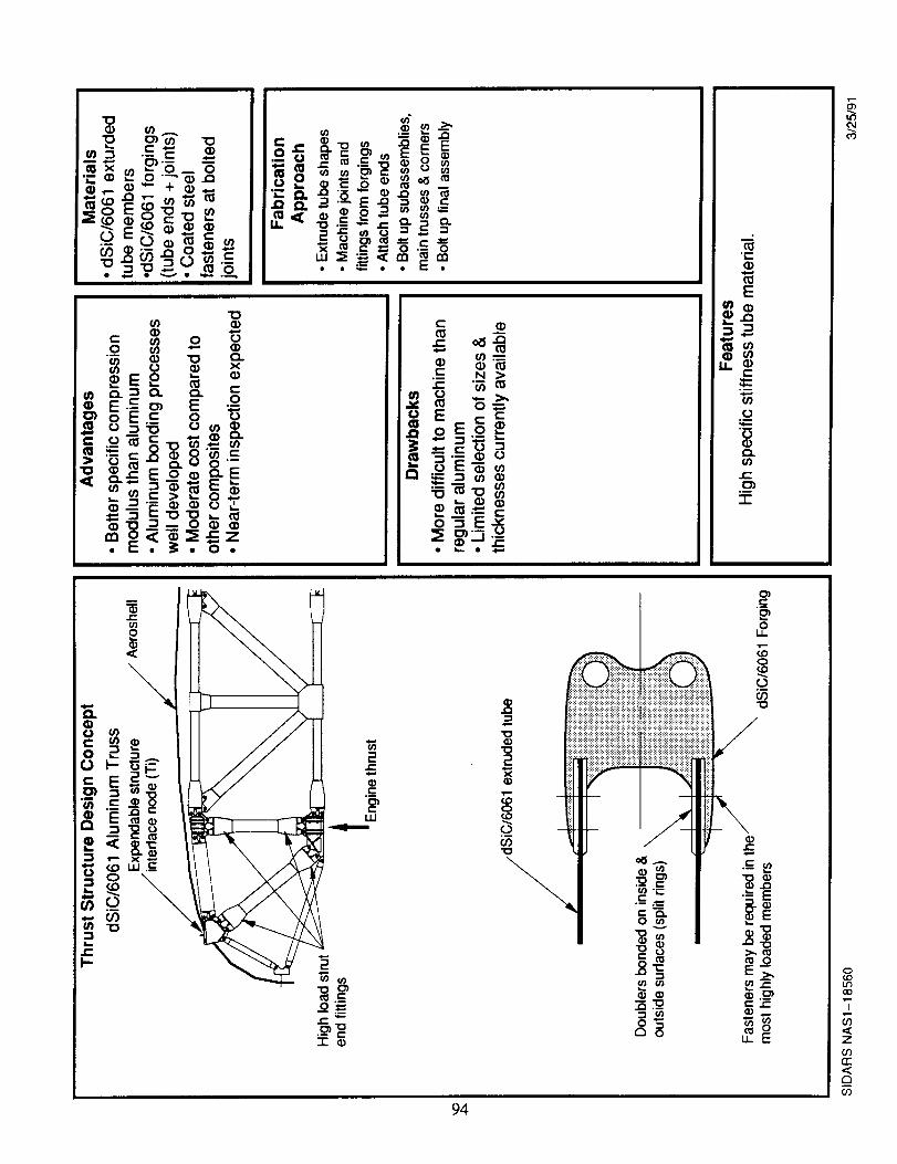
CO
0COLOCO
7
.<Z
GOrr<r_
oO
94
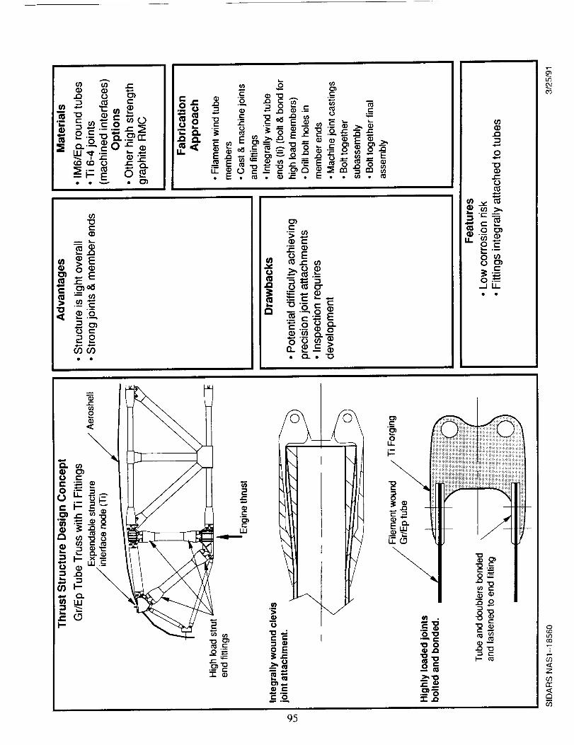
95
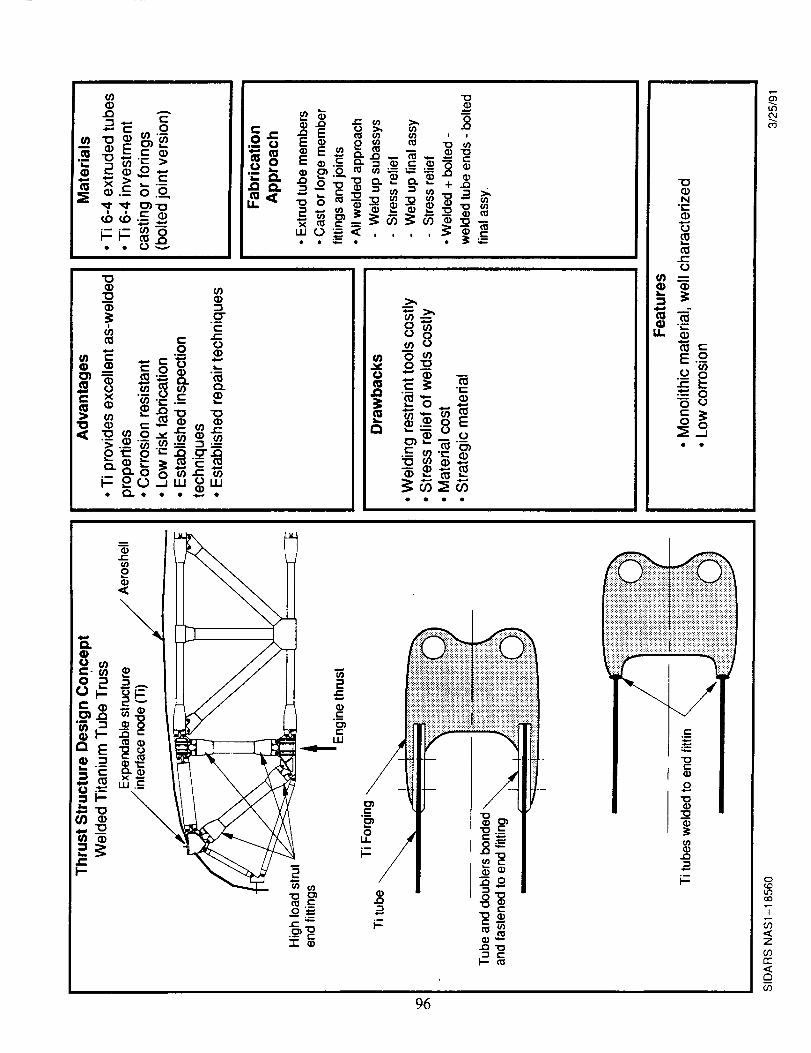
_8
LO
03
0(.0LZbCO
5-
Z
6Orr
m
(/3
96
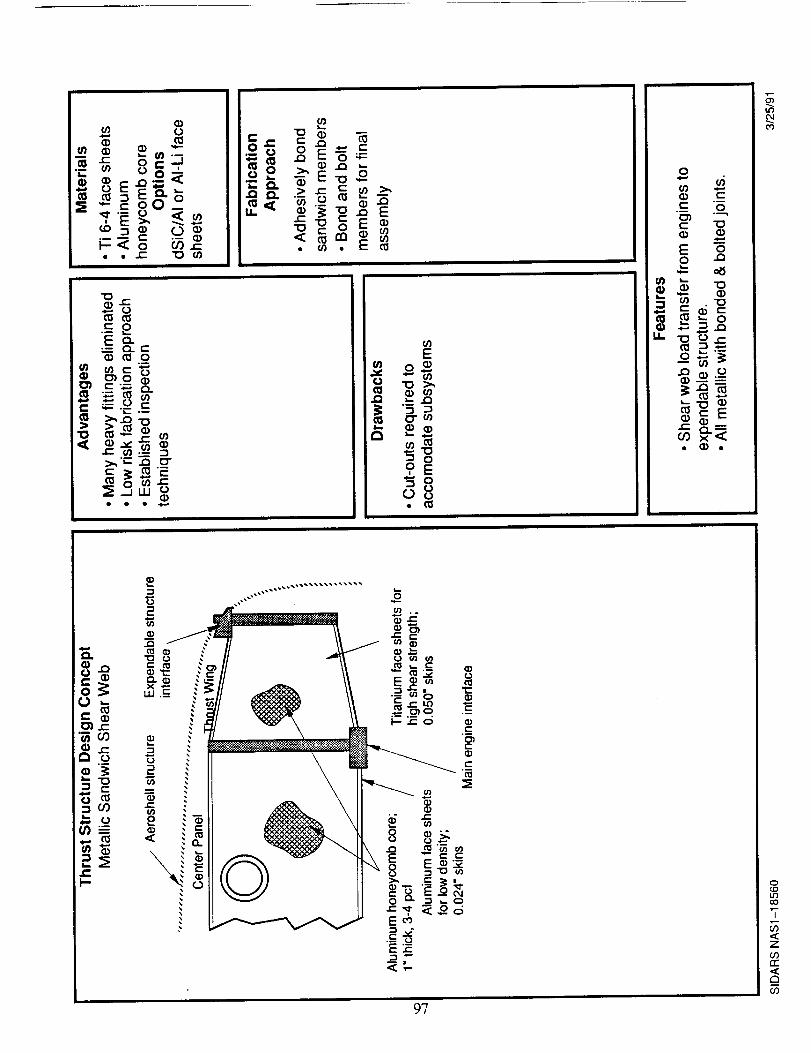
_0
= .=_.__
_o_
•-- u, _ 0- 0 _I_. _=..=__ I _ _ -_I_ a_ _ _La.O I
, _® _'_ I _'_I _-_ _ I _.__ _
_.E_
z- 0
.--Qe-a_o
o_
p,
9E
o8• ffl
£
o ._.___._
&=
g
0
g_
._ .__
li° 0
"T
Z
oorr
cO
97
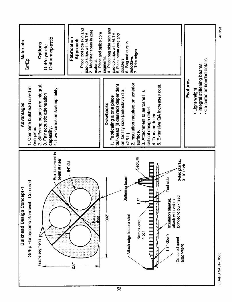
o_
0'_
,o,,.IDu'5co
3"
<zO9rr<r_
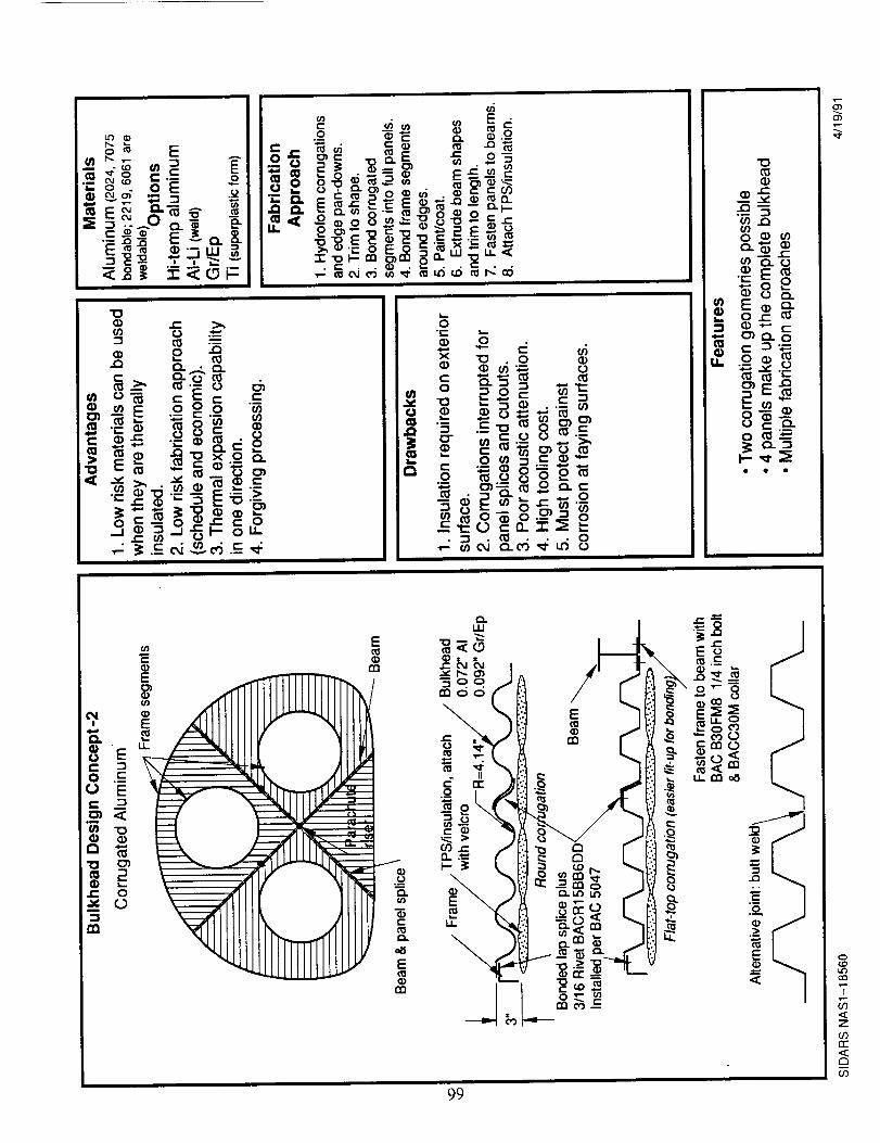
99
_3
_c_._.w c__o_ow_ 0 o_Em_0 c- C_
"._ .._ ._'
_.T. _
i
T
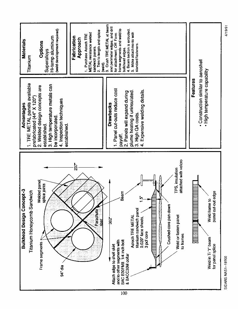
2
o__O-_
q)
tO o
_x 8 _ -_L- C
"_ _ .o• ,__
o,,__ _.___;e.; !_
"a._ ® _._,/ _
_-__ _ °-° °____ _
_ _®_'-
_-_
=o___,__
8_>,
S mo
_.-_
_g
" o
°
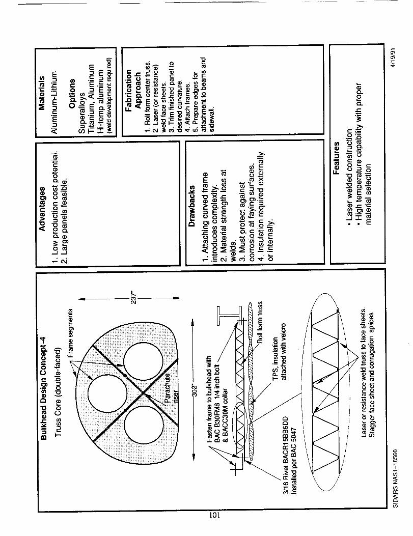
Q.
oQ.
_ _L_
_) r" "__
n=
O_
101
0
CO
Z
c'r"
if)
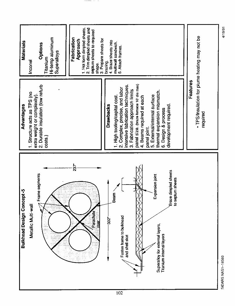
E
2
8 =
_g
r
102
o
co
<
03
<
if)
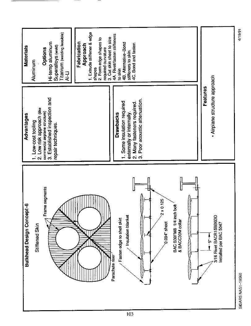
8
_,
x
___ _ __ _ _.
N
103
o
co
7
<zmrr<C_
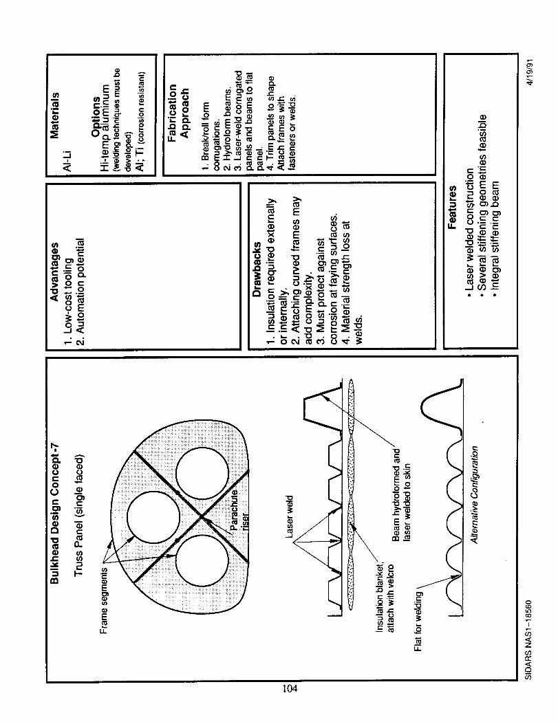
104
o(.D1.ocO
T
Zcorr<_r_co
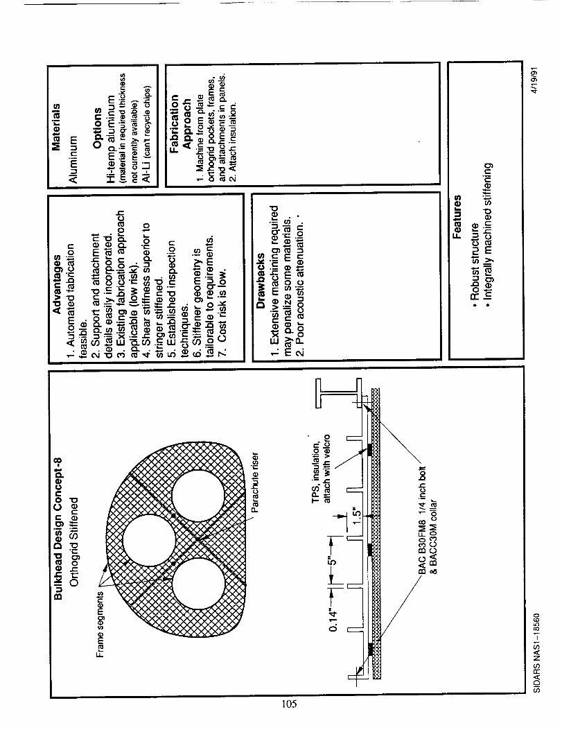
E___
°•_, ._a_ _ 0_.__
_::1._ .- ._
• N
"0
"= .9
I_ " I:::¢:: I
[o.=-- ®= [[e_ooI _ m {/)'.,_ iI_ _ I
_ _.--.- "_ 0
t.u
105
0(,0
"7
zo3rr
m
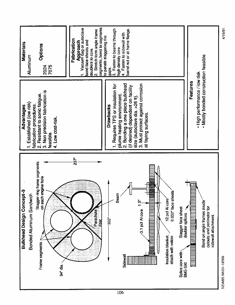
_8
106
O_
0
t_a0
I
CO
Z
_0rr
r_
U_
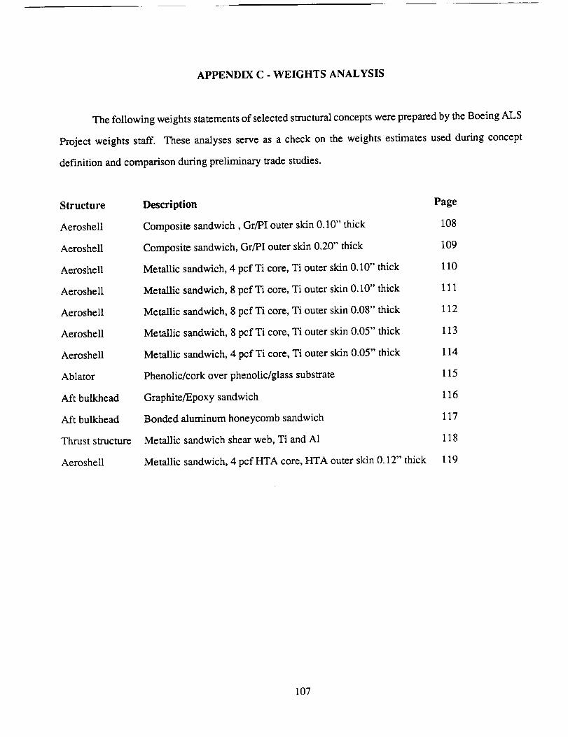
APPENDIX C - WEIGHTS ANALYSIS
The following weights statements of selected structural concepts were prepared by the Boeing ALS
Project weights staff. These analyses serve as a check on the weights estimates used during concept
definition and comparison during preliminary trade studies.
Structure
Aeroshell
Aeroshell
Aeroshell
Aeroshe11
Aeroshell
Aeroshell
Aeroshell
Ablator
Aft bulkhead
Aft bulkhead
Thrust structure
Aeroshell
Description Page
Composite sandwich, Gr/PI outer skin 0.10" thick 108
Composite sandwich, Gr/PI outer skin 0.20" thick 109
Metallic sandwich, 4 pcf Ti core, Ti outer skin 0.10" thick 110
Metallic sandwich, 8 pcf Ti core, Ti outer skin 0.10" thick 111
Metallic sandwich, 8 pcf Ti core, Ti outer skin 0.08" thick 112
Metallic sandwich, 8 pcfTi core, Ti outer skin 0.05" thick 113
Metallic sandwich, 4 pcf Ti core, Ti outer skin 0.05" thick 114
Phenolic/cork over phenolic/glass substrate 115
Graphite/Epoxy sandwich 116
Bonded aluminum honeycomb sandwich 117
Metallic sandwich shear web, Ti and A1 118
Metallic sandwich, 4 pcf HTA core, HTA outer skin 0.12" thick 119
107
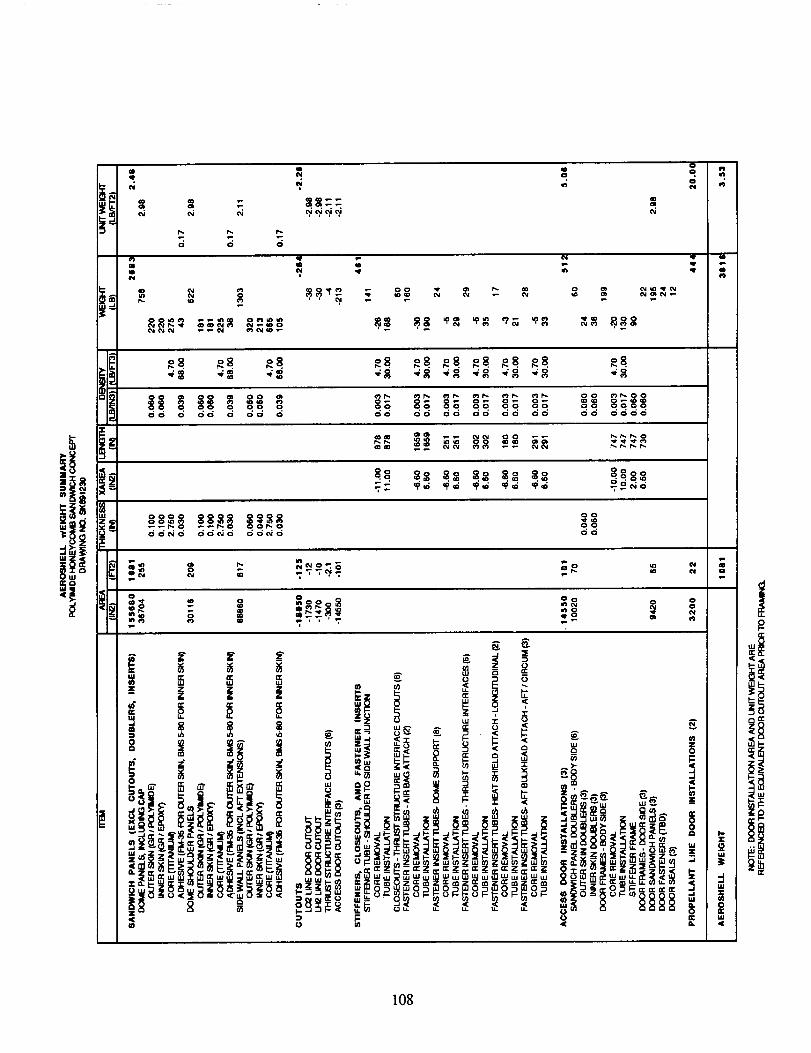
re
|!I-
|UJ
I,U
108

"r)-
di
Z
r_>.LU
I-- z
_8uJ:Z:
rs-m
0
I
:E>-
I.L
o
0 <
_:Z
ZO
F.. n"o_
109
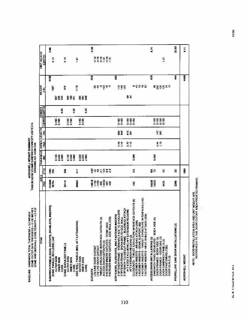
A:E0
i
141.p
IIW(/3
7==v_.g.="r_
==
m
oo oo oo od ddo oooo
II0
_z
)
_<
IO
:0
=Z_'UJ
uJ
h-
if)
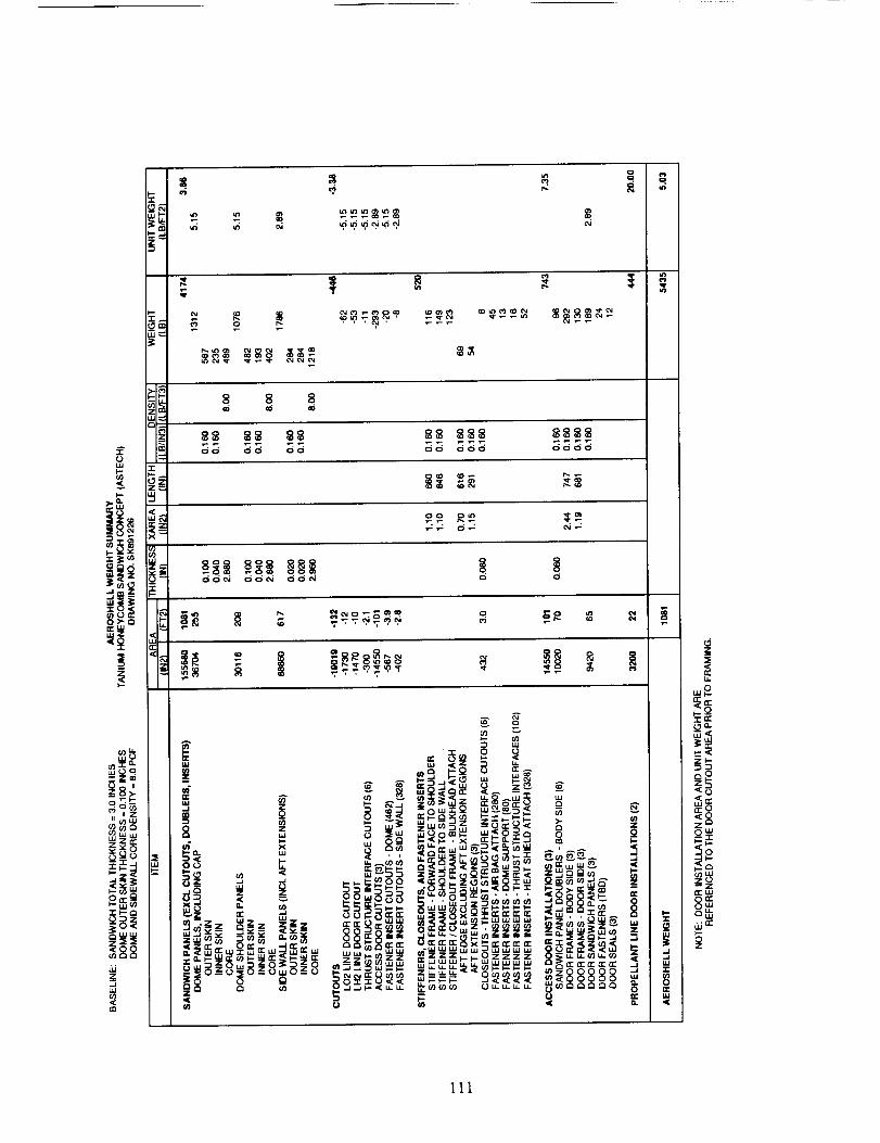
A
0W
v
l-
ee
g_
l---r
Ui4
dW4
.o_co ,Z
II (i,3 i_,I
_)uJ
oE _
3_
oo oo oo oo ooo oooo
fl
=
_.<
g
IO
ai"p-
111
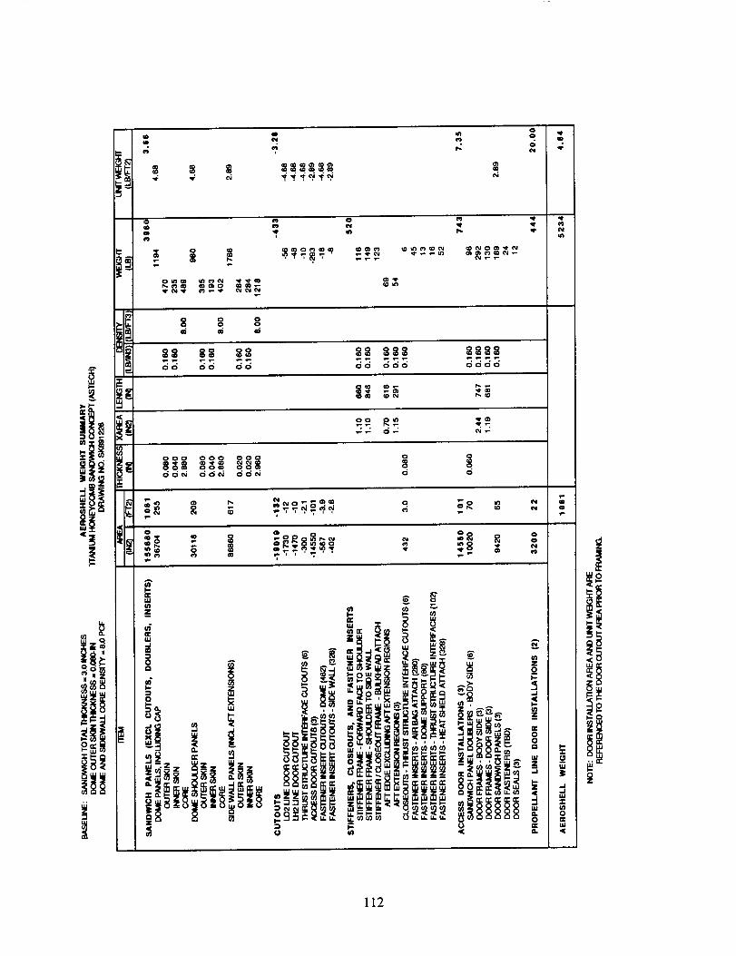
,q¢
oo 'I'
o
8 g g
O0 O0 O0 O0 000 0000
112
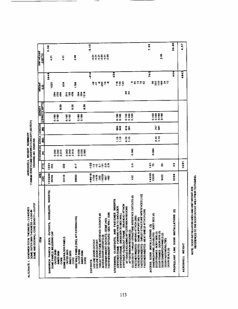
o
o.
m
m
GGG_G_
i
qP
at
I,,-
0o
iiIII 'i°_ |_m
! <
,,,, oittl_ i,_
.,e
.,,,t
,,e
o
113
-i.1
!
z_
!!i
m
Q t,ltM in o
i
8 8, o ,
88 88 88 88 888 8888oo oo oo ooo oooo
oo _ _
!i
114
o
oo o o ooo
g
_ S _S ss sss ss _S_ sss s _ _ ss_
................ 9o. . _ .ooo o oo oo oo oo ooo ooo o ooo oo ooo o o o o o
0"_'0 _ O" 00'' _00 _ _0 _d 0 0_0 _ 000 0 0
I |
e_
g
u.
o
I
I
115
i
UJ-rv.J
116
qP
m
I',.qP
i
o
c_c_ c_ oooo ooo
o_ o oo°°
Oo _o_ oO
_ oo_o _oo _oo _oo oooo ooo ooo oo
0 _ 0000
m
o
_oo _ _®® _
Aq.
_[ _ LU 0U.
/-.,r
.(
-r
.J
m
l-u.4[
117
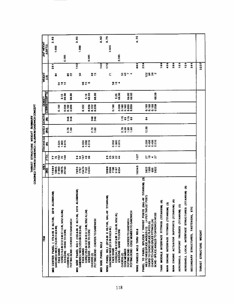
itu_
=E
_ u3
o. o. .
=o o o
N _" t_ 1- m OI
¢D N C),
O0 0
0
o .......
118
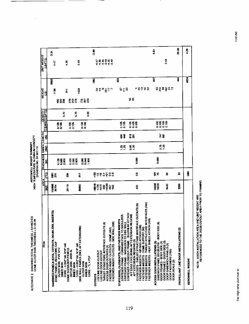
I,-
H
|
|
O0 O0 O0 O0 OQO 0000
119
.-q
"v
ft.
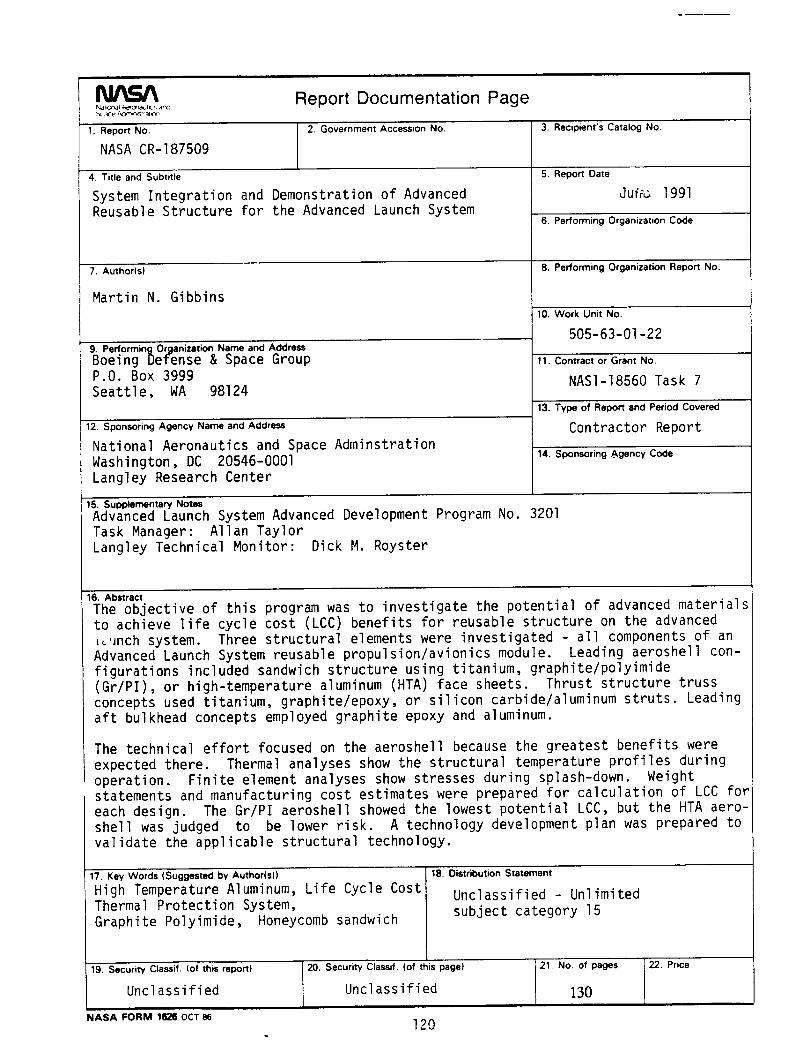
Report Documentation Page
1. Report No.
NASA CR-187509
2. Government Accession No,
4. Title and Subtitle
System Integration and Demonstration of AdvancedReusable Structure for the Advanced Launch System
7. Author(sl
Martin N. Gibbins
9. Performing Organizet_n Name and Addre_
Boeing Defense & Space GroupP.O. Box 3999Seattle, WA 98124
12. Sponsoring A_ncy Name and Addre_
National Aeronautics and Space AdminstrationWashington, DC 20546-0001Langley Research Center
3, Recipient's Catalog No.
5. Report Date
Ju_ 1991
6. Performing Organization Code
8. Performing Organization Report No.
10. Work Unit No.
505-63-01-22
11. Contract or Grant No,
NASI-18560 Task 7
13. Type of Report and Period Covered
Contractor Report
14. Sponsoring #,gency Code
15. Supp_mentaw Not_
Advanced Launch System Advanced Development Program No. 3201Task Manager: Allan TaylorLangley Technical Monitor: Dick M. Royster
16, Abstract
The objective of this program was to investigate the potential of advanced materialsto achieve life cycle cost (LCC) benefits for reusable structure on the advanced_'mch system. Three structural elements were investigated - all components of anAdvanced Launch System reusable propulsion/avionics module. Leading aeroshell con-figurations included sandwich structure using titanium, graphite/polyimide(Gr/PI), or high-temperature aluminum (HTA) face sheets. Thrust structure trussconcepts used titanium, graphite/epoxy, or silicon carbide/aluminum struts. Leadingaft bulkhead concepts employed graphite epoxy and aluminum.
The technical effort focused on the aeroshell because the greatest benefits wereexpected there. Thermal analyses show the structural temperature profiles duringoperation. Finite element analyses show stresses during splash-down. Weightstatements and manufacturing cost estimates were prepared for calculation of LCC foreach design. The Gr/PI aeroshell showed the lowest potential LCC, but the HTA aero-shell was judged to be lower risk. A technology development plan was prepared tovalidate the applicable structural technology.
17, Key Wor_ (Suggest_ by Au_or(s))
High Temperature Aluminum, Life Cycle CostThermal Protection System,Graphite Polyimide, Honeycomb sandwich
19. SecuriW Cla_if. (of this report} IZU.
Unclassified
18. Distribution Statement
Unclassified - Unlimitedsubject category 15
SecuriW Cla_if. (of this page)
Unclassified -_No. of pages130
NASA FORM 1626 OCT 86
22. Price
120
-=