NAR Level 3 Certification Package Construction
27
NAR Level 3 Certification Package Robert Winglee NAR #86834 I. Introduction Below are the details for a scratch built L3 Rocket. The objective is to build the rocket with redundancy at all levels possible to creative a robust rocket system. As such maximizing the strength of the rocket was the primary goal and not minimizing the weight of the system. Overall dimensions of the rocket are 11.25 ft long, 7.5 diameter with an estimated weight prior to construction of 12 kg. The rocket will be powered by an M1297 (75 mm/5120; 5417 N-s) with an expected apogee of about 7810 ft. With the motor loaded the rocket mass should be 16.75 kg. Recovery will be from drogue-main system with redundant electronics and with a radio beacon to aid in determining the position of rocket on landing. II. Scale Drawing Using Rock Sim (V8) the CP is 96" from the tip of the nose cone. Center of gravity without the motor loaded is at 66" from the tip of the nose cone. This is nearly 4.0 rocket diameter separation and should therefore yield stable flight. Rock Sim indicates stability factor is 3.9.
Transcript of NAR Level 3 Certification Package Construction

NAR Level 3 Certification Package
Robert Winglee
NAR #86834
I. Introduction
Below are the details for a scratch built L3 Rocket. The objective is to build the
rocket with redundancy at all levels possible to creative a robust rocket system. As such
maximizing the strength of the rocket was the primary goal and not minimizing the
weight of the system.
Overall dimensions of the rocket are 11.25 ft long, 7.5 diameter with an estimated
weight prior to construction of 12 kg. The rocket will be powered by an M1297 (75
mm/5120; 5417 N-s) with an expected apogee of about 7810 ft. With the motor loaded
the rocket mass should be 16.75 kg.
Recovery will be from drogue-main system with redundant electronics and with a
radio beacon to aid in determining the position of rocket on landing.
II. Scale Drawing
Using Rock Sim (V8) the CP is 96" from the tip of the nose cone. Center of gravity
without the motor loaded is at 66" from the tip of the nose cone. This is nearly 4.0 rocket
diameter separation and should therefore yield stable flight. Rock Sim indicates stability
factor is 3.9.
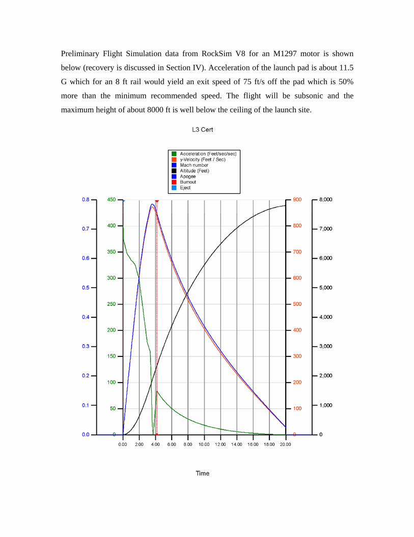
Preliminary Flight Simulation data from RockSim V8 for an M1297 motor is shown
below (recovery is discussed in Section IV). Acceleration of the launch pad is about 11.5
G which for an 8 ft rail would yield an exit speed of 75 ft/s off the pad which is 50%
more than the minimum recommended speed. The flight will be subsonic and the
maximum height of about 8000 ft is well below the ceiling of the launch site.
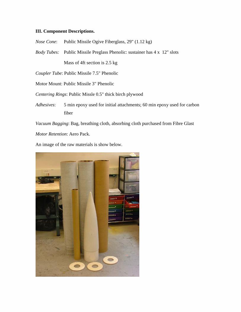
III. Component Descriptions.
Nose Cone: Public Missile Ogive Fiberglass, 29" (1.12 kg)
Body Tubes: Public Missile Preglass Phenolic: sustainer has 4 x 12" slots
Mass of 4ft section is 2.5 kg
Coupler Tube: Public Missile 7.5" Phenolic
Motor Mount: Public Missile 3" Phenolic
Centering Rings: Public Missle 0.5" thick birch plywood
Adhesives: 5 min epoxy used for initial attachments; 60 min epoxy used for carbon
fiber
Vacuum Bagging: Bag, breathing cloth, absorbing cloth purchased from Fibre Glast
Motor Retention: Aero Pack.
An image of the raw materials is show below.

Fin: Dimensions for the fins are shown below.
The backbone for the fins will be 1/16" G10 fiber glass. These fins will be epoxy
on to the motor mount system, and then carbon fibre applied to the exterior to produce
very strong fins that are mounted to both the motor tube and exterior rock body.
To allow maximum adhesive of the carbon fiber slots will be cut into the G10
fiber glass to all bonding of carbon fiber to both sides of the fin and thereby inhibits
delamination of the bonded carbon fibers. At the same time the presence of the slots
minimizes the possibility of the development of a resonance than causes fin flutter and
possible loss of fin integrity.
A four layered carbon fiber will be applied and the whole assembly vacuum
bagged. Photos of the construction will be added once construction start.
Actual placement of the fins at 90º will be aid by the construction of a fin can
box.
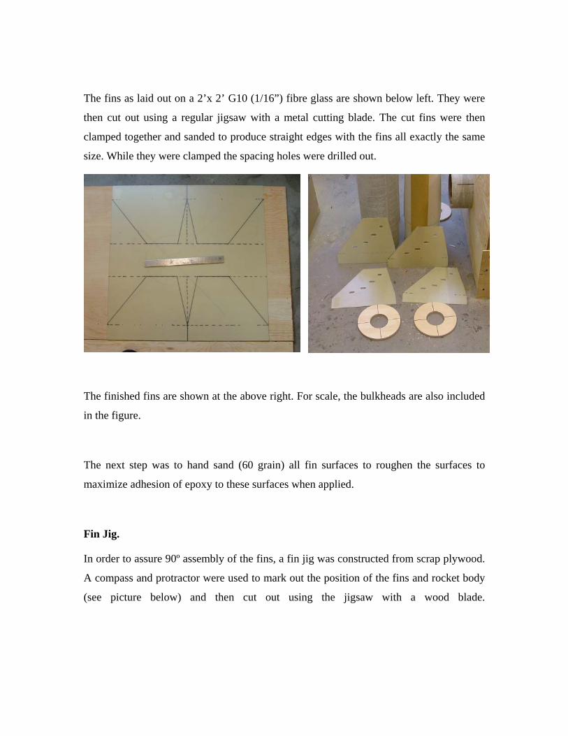
The fins as laid out on a 2’x 2’ G10 (1/16”) fibre glass are shown below left. They were
then cut out using a regular jigsaw with a metal cutting blade. The cut fins were then
clamped together and sanded to produce straight edges with the fins all exactly the same
size. While they were clamped the spacing holes were drilled out.
The finished fins are shown at the above right. For scale, the bulkheads are also included
in the figure.
The next step was to hand sand (60 grain) all fin surfaces to roughen the surfaces to
maximize adhesion of epoxy to these surfaces when applied.
Fin Jig.
In order to assure 90º assembly of the fins, a fin jig was constructed from scrap plywood.
A compass and protractor were used to mark out the position of the fins and rocket body
(see picture below) and then cut out using the jigsaw with a wood blade.
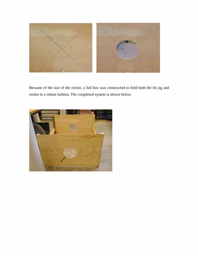
Because of the size of the rocket, a full box was constructed to hold both the fin jig and
rocket in a robust fashion. The completed system is shown below.
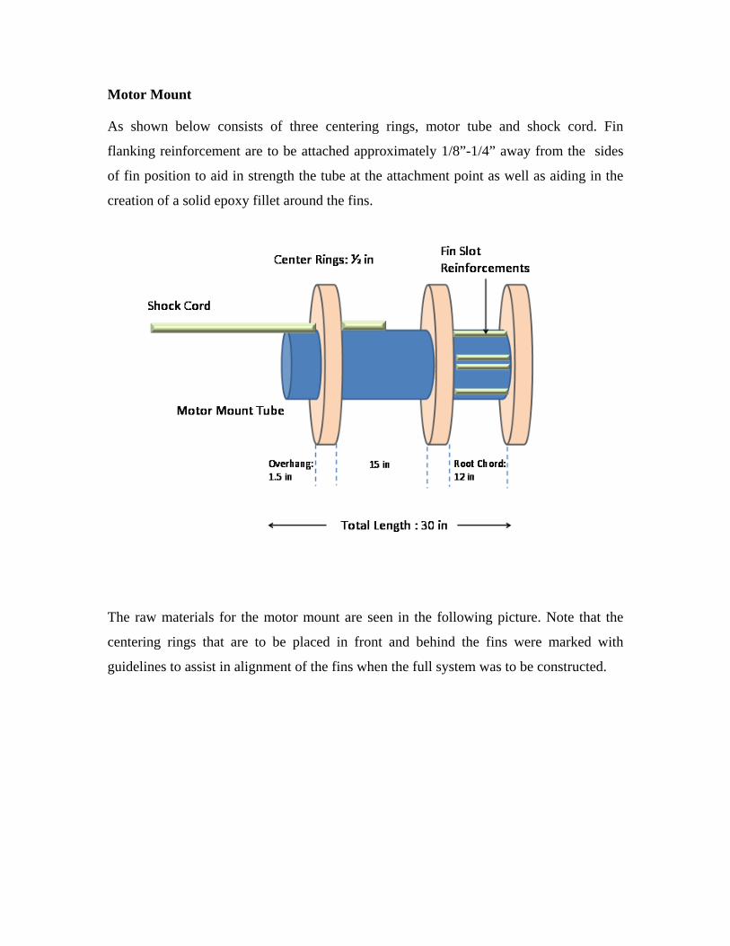
Motor Mount
As shown below consists of three centering rings, motor tube and shock cord. Fin
flanking reinforcement are to be attached approximately 1/8”-1/4” away from the sides
of fin position to aid in strength the tube at the attachment point as well as aiding in the
creation of a solid epoxy fillet around the fins.
The raw materials for the motor mount are seen in the following picture. Note that the
centering rings that are to be placed in front and behind the fins were marked with
guidelines to assist in alignment of the fins when the full system was to be constructed.

Raw Materials for the motor mount. A 12 in ruler is shown for scale.
Before assembly, a small notch was filed into the top centering ring to allow for the
passed of the shock tube with is epoxied to the motor tube. The completed assembly is
shown below.

The completed motor mount was then inserted into the sustainer body tube and
the fins were dry fitted as seen in the above picture. During the dry fitting stage, the fins
were held on with blue masking tape. Once alignment with respect all fins and slots was
confirmed, key surfaces were taped up to avoid the possibility of epoxy drops. This
included the rear parts of the body tube and either side of the fin inserts as seen below.
Once the surfaces were taped, epoxy fillets were made first around the front and
middle centering rings, and then one fin at a time using 5 min epoxy. For each fin the
epoxy fillet to the motor tube was first applied, fin inserted and allowed to dry. Then the
external fillet was applied, and allowed applied to dry. After this, the next fin was

inserted and the process repeated. Once all fins had been assembled an epoxy fillet on the
interior wall of the sustainer tube and the fin was applied. Again only one side at a time
was applied to avoid epoxy drips.
Finally, 60 min epoxy (which is less viscous than the 5 min epoxy) was dripped
down onto the middle centering ring to ensure that a good continuous fillet was made to
all surfaces in the region. Pictures of the inner and outer fillets are shown below.
The completed fin can out of the box.

Preparations for Carbon Fiber Application
The first step is to coarse (60) grain sand the external epoxy fillets and body tube
areas around the fins.
Second step is to create a paper stencil of the fin section. To do this we took a
large piece of paper and press it against the fins and trace out the shape and then cut to
size as shown below.
Since the weakest point which can be undone by flight stresses is the joint of the
fin to the rocket body we apply four layers of carbon fiber of different sizes. The different
sizes saves weight and material while maximizing strength and minimizing the thickness
of the fins, thereby yielding maximum performance.
The four sizes shown below are
(1) thin strip along the joint
(2) slightly wider but again concentrating on the joint
(3) piece that is the exact size of the template that covers one side only
(4) the largest piece that is about 2 inches wider than the template to allow
wrapping of the piece from one side to the next. For this last piece, slots are
cut into the fiber to allow easy folding of the material across the edges of the
fin.
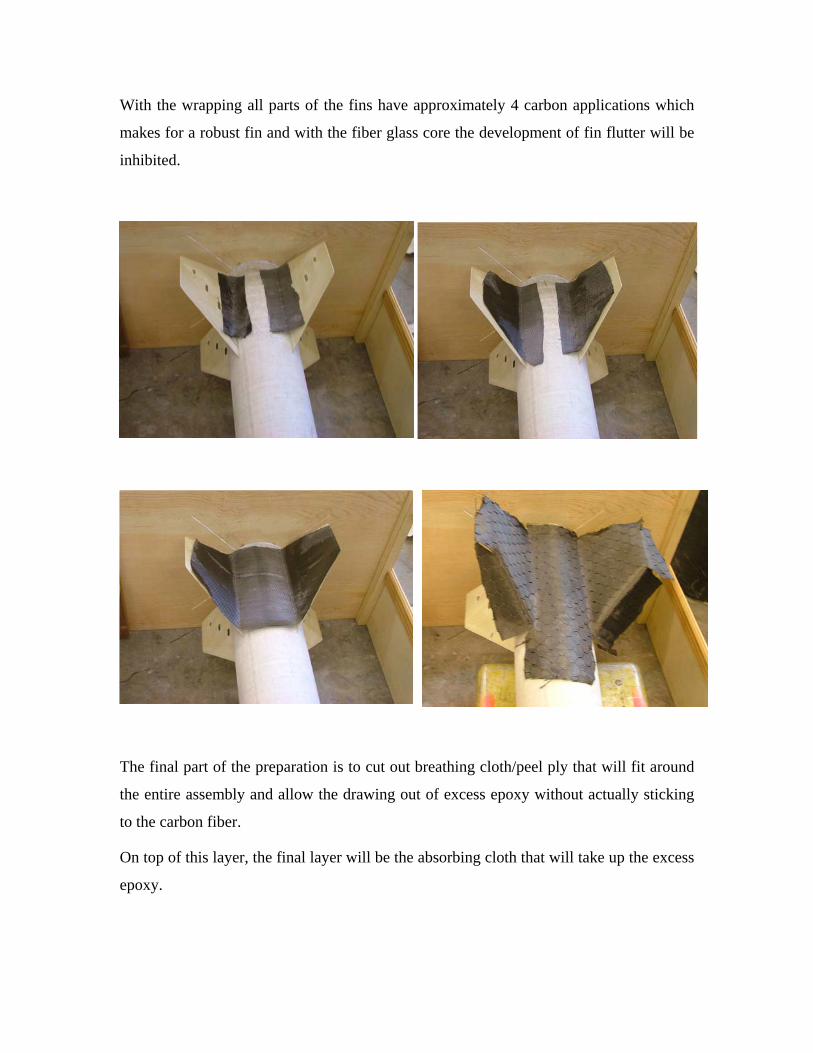
With the wrapping all parts of the fins have approximately 4 carbon applications which
makes for a robust fin and with the fiber glass core the development of fin flutter will be
inhibited.
The final part of the preparation is to cut out breathing cloth/peel ply that will fit around
the entire assembly and allow the drawing out of excess epoxy without actually sticking
to the carbon fiber.
On top of this layer, the final layer will be the absorbing cloth that will take up the excess
epoxy.
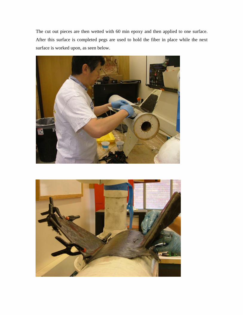
The cut out pieces are then wetted with 60 min epoxy and then applied to one surface.
After this surface is completed pegs are used to hold the fiber in place while the next
surface is worked upon, as seen below.

The picture top the left shows the fins after the carbon fiber has cured. The rough edges
were then cut off and the entire area was sanded. Imperfection in the carbon fiber layers
were filled with epoxy and additional sanding was performed to attain a reasonably
smooth surface. A transparent gross coat was applied so that the original carbon fiber
material can easily be seen.
For motor retention we used a Aeropack RA75 from
Rocketry Warehouse which is shown to the left.
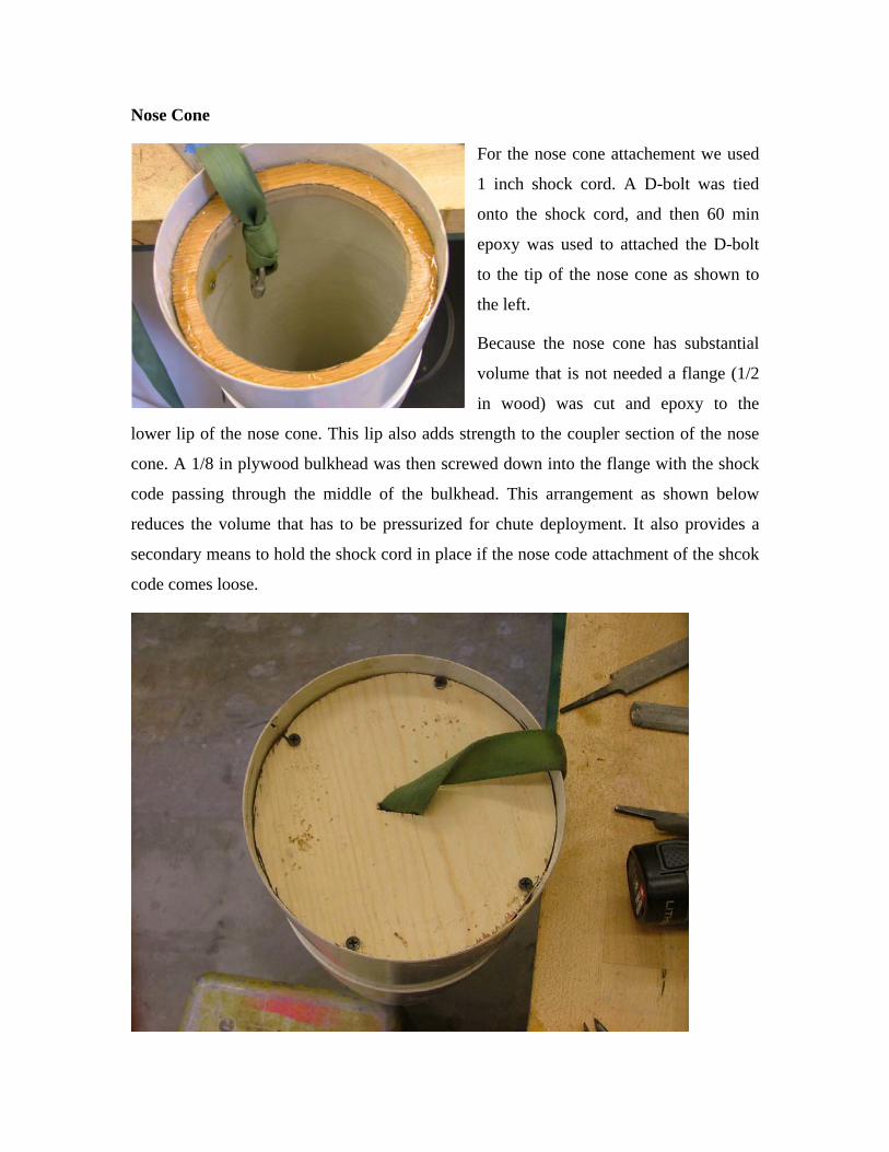
Nose Cone
For the nose cone attachement we used
1 inch shock cord. A D-bolt was tied
onto the shock cord, and then 60 min
epoxy was used to attached the D-bolt
to the tip of the nose cone as shown to
the left.
Because the nose cone has substantial
volume that is not needed a flange (1/2
in wood) was cut and epoxy to the
lower lip of the nose cone. This lip also adds strength to the coupler section of the nose
cone. A 1/8 in plywood bulkhead was then screwed down into the flange with the shock
code passing through the middle of the bulkhead. This arrangement as shown below
reduces the volume that has to be pressurized for chute deployment. It also provides a
secondary means to hold the shock cord in place if the nose code attachment of the shcok
code comes loose.
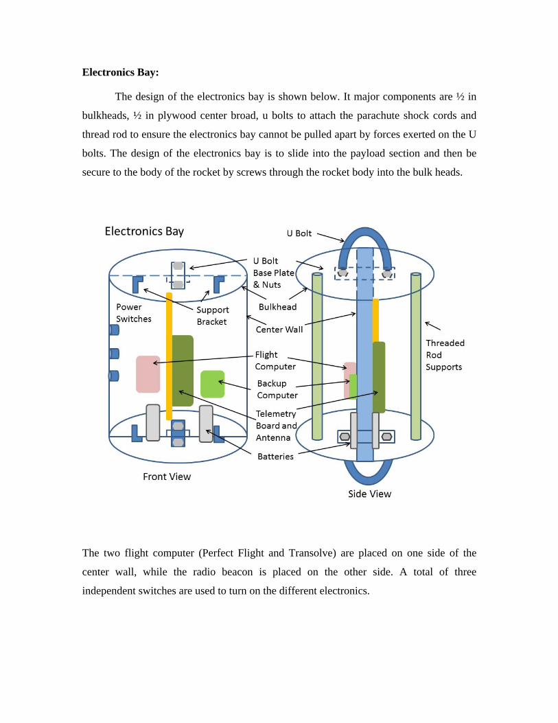
Electronics Bay:
The design of the electronics bay is shown below. It major components are ½ in
bulkheads, ½ in plywood center broad, u bolts to attach the parachute shock cords and
thread rod to ensure the electronics bay cannot be pulled apart by forces exerted on the U
bolts. The design of the electronics bay is to slide into the payload section and then be
secure to the body of the rocket by screws through the rocket body into the bulk heads.
The two flight computer (Perfect Flight and Transolve) are placed on one side of the
center wall, while the radio beacon is placed on the other side. A total of three
independent switches are used to turn on the different electronics.

The circuit layout for the electronics is shown above. The actual physical layout of the
payload section is shown on the next page. Holes in the payload section were cut to
provide access to these switches.

IV. Recovery System.
Shoot deployment will be performed by two independent systems. The two
systems are:
Transolve P6K uses a barometric peak reading (up to 25,000ft) with main
deploying at 800ft
Perfectflite Hi-Al 45k uses a barometric peak reading (up to 45,000ft) and main
deploying at 700ft.
Drogue chute will be in the top part of the sustainer – estimate size required for
the drogue is 72" and the main is 120" diameter to be attached to U-bolts on the
electronics bay and motor mount/nose cone with 1” nylon strap. (Verification of size will
be made when the exact weight of the rocket is known).
Powder charges will be determined using the formulas at
http://www.vernk.com/EjectionChargeSizing.htm
Deployment charge equation: n = 0.00052 F L where: n = Grams of 4fg BP, F = Force desired (PSI) L = Length of deployment bay In the following it is assumed F =350 lbs is sufficient as recommended by the above site. Drogue Deployment Charge: L = 18” requiring about 3.3 grams. Allowing for marginal of error target charge will be 4 gms. Validation testing will have to way for construction of the system. Main Deployment Charge: L = 24” requiring about 4.4 grams. Allowing for marginal of error target charge will be 5.0gms. Validation testing will have to way for construction of the system. The expected descent rate as derived from RockSim V8 is show below. Under drogue the
rocket will come down at between 35-40 ft/s. Under main this will be reduced to about 22
ft/s which should be sufficient to provide a soft landing.

Telemetry will be provided by a UW built radio beacon that has been successfully flown
on multiple flights over the last few years. This system has flown with the Perfectflite as
backup but a full system test of the compatibility of all three systems will have to be
made after assembly of the electronics bay.

Making of the Powder Charges.
The power charges are made from GOEX Black Rifle Powder with 2 gm measuring cups,
J-Tek e-match, Public Missile Charge Cylinder, a Latex glove, and insulating tape. The
individual components are shown below. The preparation is performed over a large sheet
of paper so that spillage of black powder can be collected and returned to the container.
The fingers of the latex glove provide a cheap means for a spill proof container
for black powder. Each glove fingers is cut, and the black powder is measured out and
then poured into one of the cut
off glove fingers. The e-match
is then positioned into the
center of the black powder and
the latex taped to the e-match
as shown to the left. This
creates a leak proof bag around
the e-match.
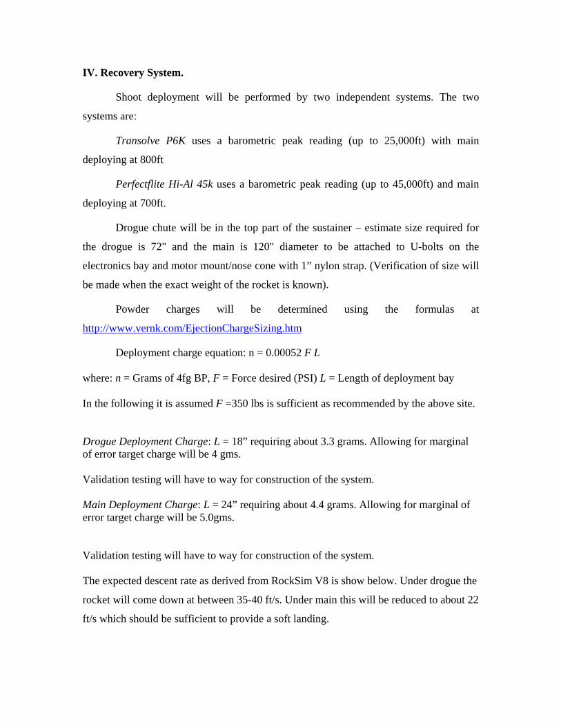
The end of the wire is threaded through the charge holder and the tip of the latex
portion is then carefully guided into the charger holder with the taped section pointing out
(left hand side). This allows maximum amount of powder charge to be in the holder. The
rest of the charge is taped down (right hand side) so there is no change of any component
coming loose during flight.
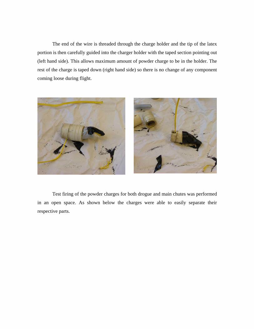
Test firing of the powder charges for both drogue and main chutes was performed
in an open space. As shown below the charges were able to easily separate their
respective parts.
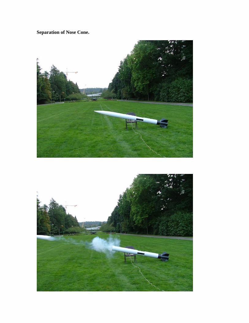
Separation of Nose Cone.
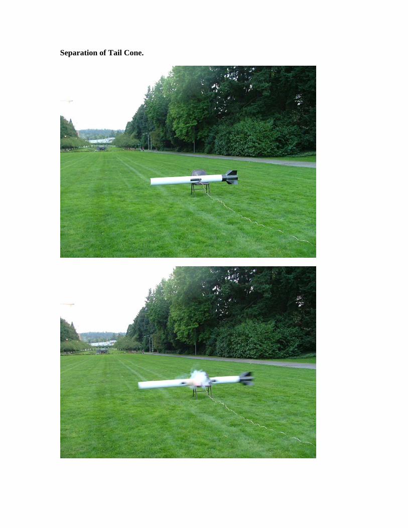
Separation of Tail Cone.

Rocket Ready for Flight.

Preflight Checklist Necessary Equipment:
Phillips screw driver, Standard screw driver, mounting screws, e-matches, igniter,wire cutters, sandpaper, ladder, putty.
Rocket Assembly: 1. Build 4 wrapped black powder charges around an e‐match.
2. Load motor grain into casing.
3. Check batteries on payload section
4. Test avionics; power off avionics
5. Install payload section
6. Attach mounting screws
7. Ensure switches are accessible and can be powdered on.
8. Pull wires through hole for emergency power down.
9. Seal payload bay with putty
10. Ensure parachutes and chute protectors are tied to the shock codes
11. Ensure shock cords are attached to payload, nose cone and tail section
12. Load ejection charge into primary chute ejection system, and connect e‐match leads to
the ejection card electronics.
13. Slide tail section into place; insert shear pins
14. Slide nose cone into place
15. Insert motor into motor mount and lock into place.
16. Verify position of Center of Mass
17. Gather igniter and inspect for damage and ensure leads are crossed
18. Gather sand paper and wire cutter, ladder
19. Take rocket to RSO for inspection.
20. If okayed for launch proceed to assigned launch rail 21. Mount rocket on launch rail 22. Activate radio beacon; verify radio reception 23. Activate flight computers; verify audio tones 24. Install igniter 25. Attach leads to igniter 26. Test for continuity 27. Take photos 28. Clear site of all tools 29. Return to behind RSO

Post‐Flight:
1. Inspect rocket for possible unspent powder charges
2. If potential unspent charges are present cut emergency cutoff
3. Count beeps for altitude
4. Power off avionics
5. Re‐fold parachutes
6. Return to launch site