Design of a Remedy to Control NAPL Transport and Allow for Flexible Redevelopment

SRSNE Site Group
Remedial Design Work Plan Attachment F
NAPL Mobilization Assessment and Mitigation Plan
Solvents Recovery Service of New England, Inc. (SRSNE) Superfund Site Southington, Connecticut
November 2010

Remedial Design Work Plan Attachment F NAPL Mobilization Assessment and Mitigation Plan Solvents Recovery Service of New England, Inc. (SRSNE) Superfund Site Southington, Connecticut
Prepared for:
SRSNE Site Group
Prepared by:
TerraTherm, Inc. 10 Stevens Road Fitchburg MA 01420 Phone: (978) 343-0300 Fax: (978) 343-2727
Our Ref.:
9-101
Date:
November 2010

i
Table of Contents
Executive Summary iii
1. Introduction 1
2. Assessment and Mitigation of DNAPL Mobilization Risk During Well Installation 4
2.1 Introduction 4
2.2 Selection of Appropriate Drilling Method 4
2.3 Construction of Borings/Wells 5
2.4 Installation of Borings/Wells 8
3. Assessment and Mitigation of DNAPL Mobilization During Heating and Operation 15
3.1 Literature Review and Detailed Discussion of Properties and Mechanisms 15
3.1.1 Eutectic Point: The Lower Boiling Point of a DNAPL-Water Mixture 15
3.1.2 Vertical Mobilization: Critical Pool Height and DNAPL Entry Through Capillary Barriers 16
3.1.3 Rate of Heating of DNAPL Pools Relative to Surrounding Material 19
3.1.4 Removal of DNAPL Pools and Risk for Vertical Mobilization 20
3.2 Summary of DNAPL Mobilization Risk During Heating/Operation 22
4. DNAPL Migration Monitoring and Mitigation 27
5. References 28
ii
Table of Contents
Figures
Figure F-1. Well construction detail for TCH heater well and co-located vapor collector well (618 total).
Figure F-2. Well construction detail for temperature (50 total) and pressure monitoring points (25 total).
Figure F-3a. Drilling approach.
Figure F-3b. Setting of thermal well and initial grouting process.
Figure F-3c. Thermal well grouting and completion.
Figure F-4. Vapor pressure curves for water, TCE, and a zone where both are present.
Figure F-5. Temperature dependency of interfacial tension (IFT) for a PCE-water system and the difference in density between PCE DNAPL and water and the calculated critical pool height relative to ambient temperature (assuming constant contact angle).
Figure F-6. DNAPL behavior as a function of time and temperature at the edge of a DNAPL pool nearest a thermal conduction heater.
Figure F-7. DNAPL in immediate proximity to heater well is removed soon after start up of TCH system.
Figure F-8. Comparison of starting and post treatment soil concentrations at a TCH site in SC demonstrating no downward mobilization of DNAPL.
Figure F-9. Comparison of starting and post treatment soil concentrations at a TCH site in Richmond, CA demonstrating no downward mobilization of DNAPL.

iii
NAPL Mobilization Assessment and Mitigation Plan
SRSNE Superfund Site Southington, Connecticut
Executive Summary
The non-aqueous phase liquid (NAPL) Mobilization Assessment and Mitigation Plan focuses on the potential for dense non-aqueous phase liquid (DNAPL) mobilization and the safety measures that will be implemented to prevent mobilization and to mitigate it should it occur.
It should be noted that NAPL could possibly already exist in the bedrock below some portions of the thermal treatment area, and at locations downgradient of it. The thermal design is selected and will be optimized to minimize the risk of further DNAPL migration into the rock.
DNAPL Mobilization during Heating and Operation
For NAPL source areas, and especially DNAPL source areas, the key challenge is to remove, and not spread, the DNAPL. The chemical and physical properties of DNAPL suggest that changes to its chemical properties do not significantly affect the maximum stable pool height that a capillary barrier can support and thus do not result in an appreciable increase in the risk of vertical mobilization of a pool. In fact, if the contact angle is unaffected, a raise in temperature will lead to a more stable DNAPL condition.
The maximum stable thickness of continuous DNAPL without penetrating a capillary barrier below the water table, also named the critical pool height, can be estimated by the following equation [Hunt et al. 1988; Mercer and Cohen 1990; Pankow and Cherry 1996]:
)(gr)cos(2z
wnfinern ρ−ρ⋅⋅
φ⋅σ⋅=
where
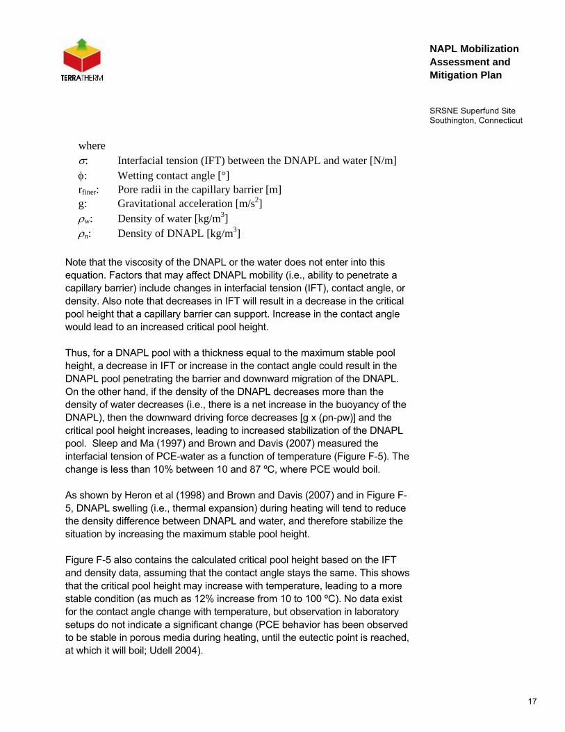
σ: Interfacial tension (IFT) between the DNAPL and water [N/m]
φ: Wetting contact angle [°]
rfiner: Pore radii in the capillary barrier [m]
g: Gravitational acceleration [m/s2]

iv
NAPL Mobilization Assessment and Mitigation Plan
SRSNE Superfund Site Southington, Connecticut
ρw: Density of water [kg/m3]
ρn: Density of DNAPL [kg/m3]
Note that the viscosity of the DNAPL or the water does not enter into this equation. Factors that may affect DNAPL mobility (i.e., ability to penetrate a capillary barrier) include changes in interfacial tension (IFT), contact angle, or density.
DNAPL swelling (i.e., thermal expansion) during heating will tend to reduce the density difference between DNAPL and water, and therefore stabilize the situation by increasing the maximum stable pool height.
In Situ Thermal Desorption (ISTD)/Thermal Conduction Heating (TCH) ensures efficient and effective removal of DNAPL pools and minimizes the risk of vertical mobilization. DNAPL present in the treatment zone will eventually be boiled and vaporized and removed from the subsurface via the heater-vacuum wells as the pools are heated from the sides, and vapors are generated and travel towards low-pressure locations. Furthermore, because the entire treatment zone is kept under a vacuum and the steam and contaminant vapors are extracted from the subsurface simultaneously with the heating, condensation of the steam and contaminants is minimized. This prevents the formation of significant DNAPL condensation banks, thus reducing the potential for vertical mobilization. When DNAPL pools are vaporized, the vapors can migrate into cooler zones and condense. Since vapors have significant buoyancy compared to the groundwater, they will tend to migrate upwards or directly towards low pressure points such as the extraction wells.
Mobilization of NAPL during Well Installation
Approximately 670 borings will be installed to the bedrock surface (a minimum of 620 of these borings will extend several feet into the bedrock) across the Site. While it cannot be accurately predicted how many of the well installations will pass through an area of potentially mobile NAPL, it is highly probable that a significant number of wells will encroach upon, or penetrate the NAPL.
Based on the geology, the presence of DNAPL, potential health and safety concerns, cuttings disposal, and overall costs, wells will be installed using sonic drilling methods. Sonic drilling well installation offers significant protection against possibly mobilizing NAPL during well installation. A standard 4 x 6

v
NAPL Mobilization Assessment and Mitigation Plan
SRSNE Superfund Site Southington, Connecticut
sonic drilling system will be used for advancing the borehole and installation of the heater wells. The 4 x 6 system consists of a 4” core barrel (4.5” outer diameter (OD), 3.75” inner diameter (ID)) and a 6” outer casing (5.5” OD, 4.75 ID). The core barrel fits snugly within the outer casing with ~1/8” clearance between the outside of the core barrel and the inside wall of the casing.
Heater wells will be installed using a carbon steel outer casing, and thin stainless steel inner liner, and extend approximately three feet into bedrock. Vapor collector wells will be installed 6 feet (ft) from the heater wells using a 6 ft stainless steel screen and carbon steel riser. The total depth of vapor collector wells will depend on Site geology, but it is assumed to be approximately 8 ft below ground surface (bgs).
Approximately 50 temperature monitoring points will be installed using threaded carbon steel pipe with an end cap and extending to the top of bedrock (approximately 16 ft). Approximately 25 combined vapor/pressure and water level monitoring points will consist of 10 ft. stainless steel screens and a carbon steel riser. The total depth of the combined vapor/pressure/water level monitoring points will depend on Site geology, but it is assumed to be approximately 12 ft bgs.
DNAPL Migration Monitoring and Mitigation
Prior to treatment startup, wells located downgradient of the TTZ and upgradient of the NTCRA will be gauged for NAPL. During treatment, wells will be monitored weekly for the presence of NAPL. Should NAPL be observed, it will be removed immediately using a bailer or pump.

1
NAPL Mobilization Assessment and Mitigation Plan
SRSNE Superfund Site Southington, Connecticut
1. Introduction
This document has been prepared on behalf of the SRSNE Site Group, an unincorporated association of Settling Defendants to a Consent Decree (CD) and Statement of Work (SOW) for the Remedial Design/Remedial Action (RD/RA) at the Solvents Recovery Service of New England, Inc. (SRSNE) Superfund Site (Site) in Southington, Connecticut. The CD was lodged on October 30, 2008 with the United States District Court for the District of Connecticut in connection with Civil Actions No. 3:08cv1509 (SRU) and No. 3:08cv1504 (WWE). The CD was entered by the Court on March 26, 2009.
The NAPL Mobilization Assessment and Mitigation Plan was prepared per the requirements of the RD/RA CD Scope of Work (SOW), which suggests that certain pre-design studies and planning be undertaken prior to the design of the thermal treatment remedy for the site. Specifically, Section V.C.1.f of the SOW states that “A plan shall be prepared that identifies measures to be taken to address potential downward mobilization of dense non-aqueous phase liquid (DNAPL), minimize the potential for vapor releases, and identify safety measures to be put in place during implementation of in-situ thermal treatment.”
This plan focuses on the potential for DNAPL mobilization and the safety measures that will be implemented to prevent mobilization and to mitigate it if it occurs. The Conceptual Design will present a detailed discussion of system features designed to minimize vapor releases. Notably, these include a vapor barrier over the entire treatment area and a network of vapor extraction wells to apply and sustain a vacuum in the vadose zone of the treatment system to remove steam and vapors from the subsurface formed during heating. Furthermore, the above ground vapor piping and treatment equipment will be kept under vacuum to minimize the potential for leaks. Vapor releases during drilling and installation of the subsurface components of the thermal treatment system will be minimized by the use of sonic drilling methods and the extraction of soil from the subsurface inside core barrels. The soil will be extruded from the core barrels directly into roll-offs equipped with tight fitting lids.

2
NAPL Mobilization Assessment and Mitigation Plan
SRSNE Superfund Site Southington, Connecticut
The Thermal Treatment Monitoring Plan (Attachment B of the RDWP) addresses monitoring for vapor emissions within the work area along the treatment area fence line. The Thermal Treatment Monitoring Plan also includes mechanisms for notifying the EPA and the community in the event of a reportable exceedance. Attachment C, the Thermal Treatment Performance Criteria Work Plan describes the monitoring, sampling, and analyses that will occur during implementation of the thermal remedy to evaluate performance of both the below and above ground components of the system and to verify that emissions from the vapor and liquid treatment systems are within acceptable limits to ensure the safety and health of on-site workers, the community, and the environment.
In addition to the safety measures included in the Thermal Treatment Monitoring Plan, the project Health and Safety Plan (Attachment D of the POP) will provide a detailed discussion of worker health and safety issues associated with the construction, implementation, and decommissioning of the thermal treatment system. The Health and Safety Plan will also present the measures and procedures that will be followed to protect on-site workers.
The following summarizes the primary factors that could result in non-aqueous phase liquid (NAPL) mobilization at the Site:
• Drilling and installation of heater wells
- Increased pore pressures
- Vibration
- Drag down
- Creation of a pathway
• Operation of the ISTD system and heating of subsurface
- Direct pool mobilization due to the effects of heating on the capillary force balance (i.e., decreases in interfacial tension and contact angle/wettability)
- Increased hydrostatic pressures

3
NAPL Mobilization Assessment and Mitigation Plan
SRSNE Superfund Site Southington, Connecticut
- Condensation of CVOC vapors outside the heated zone
The primary objectives of this NAPL Mobilization Assessment and Mitigation Plan are to:
• Assess the potential for NAPL mobilization during installation and operation of the ISTD system
• Describe drilling methods that will be used to minimize the potential for vertical mobilization of NAPL during well installation
• Describe a monitoring program to detect mobilization if it occurs
• Describe mitigation measures if NAPL is mobilized
It should be noted that NAPL is likely to exist in the bedrock below some portions of the thermal treatment area, and at locations downgradient of it. The thermal design is selected and will be optimized to minimize the risk of further DNAPL migration into the rock.

4
NAPL Mobilization Assessment and Mitigation Plan
SRSNE Superfund Site Southington, Connecticut
2. Assessment and Mitigation of DNAPL Mobilization Risk During Well Installation
2.1 Introduction
It is currently projected that approximately 670 borings will need to be installed to the bedrock surface (a minimum of 620 of the borings will extend several feet into the bedrock) across the site. While it cannot be accurately predicted how many of the well installations will pass through an area of potentially mobile NAPL, it is highly probable that a significant number of wells will encroach upon or penetrate the NAPL.
The following sections describe how the wells will be installed to minimize the risk of potential NAPL migration during well installation.
2.2 Selection of Appropriate Drilling Method
Because of their small diameter (3.5-inch O.D.), TerraTherm’s heater well casings have been installed using a variety of drilling methods including, hollow-stem augers (H-S-A), air rotary, crane mounted vibratory hammer, direct push (e.g., Geoprobe™), and sonic. Selection of the appropriate drilling method depends on:
• Site geology,
• Depth,
• Potential for NAPL mobilization,
• Production and disposal of drill cuttings,
• Health and safety concerns associated with exposure to contaminant vapors, and
• Drilling cost.
The primary requirement is a cased hole to the required depth, within which the heater casing can be installed. The diameter of the cased hole can be as small as 4 inches.

5
NAPL Mobilization Assessment and Mitigation Plan
SRSNE Superfund Site Southington, Connecticut
For the SRSNE Site, the geology, DNAPL presence, health and safety concerns, cuttings disposal, and costs has been carefully evaluated and, based on the evaluation, sonic drilling has been selected as the most advantageous approach.
Sonic drilling methods will be used to install 6-inch drill casing to the desired depth for installation of the heater wells. Sonic drilling can be used to penetrate the concrete (up to 8" thick) that exists in places under the asphalt cover. Details pertaining to the proposed drilling and installation methods for the heater and vapor recovery wells and the temperature and pressure monitoring points are provided further below in Section 2.4.
Sonic drilling will provide significant protection against unintended NAPL migration during drilling and well installation:
• The sonic method results in a tight seal between the outside of the drill casing and the borehole wall, unlike Hollow-Stem Augers (HSA), which actively mixes soil along the entire length of the borehole and does not provide a tight seal.
• The sonic method has flexibility in advancing two concentric, smooth-wall casings; it is proposed that, if possible, the outer casing will be advanced only to the top-of-rock surface, and will isolate the overburden while the inner casing drills the required socket in the top of rock to facilitate heater-well installation into the upper portion of the bedrock.
Furthermore the sonic method will result in minimal production of cuttings and the cuttings can be efficiently and safely handled since they will be removed from the subsurface in a core barrel and directly deposited into a bin, thereby minimizing handling, odors, and exposure to contaminant vapors.
2.3 Construction of Borings/Wells
Figure F-1 provides the construction schematics for the TCH heaters and co-located vapor extraction points (618 total).

6
NAPL Mobilization Assessment and Mitigation Plan
SRSNE Superfund Site Southington, Connecticut
Bedrock
Fill/topsoil
Vapor Collector2-inch SS screen
and C.S. riser pipe
0
4
8
12
16
20
24
Grout Seal
TCH well3-inch Sch. 40 C.S. Pipe
with End Cap(3.5-inch O.D.)
Vapor cap
Dep
th (f
t)
4”-6”
Till
4”
Sand
3 ft
19 ft(est. avg.)
Heater
Outwash
Figure F-1. Well construction detail for TCH heater well and co-located vapor collector well (618 total) for average site conditions.
The heater wells will consist of a 3-inch carbon steel outer casing with a thin-walled, stainless steel liner on the inside. The heater well can and liner will have welded joints to prevent water and/or steam from entering the well and potentially contacting the energized heater elements. Assuming an average depth to the top of bedrock of 16 feet (ft) the average borehole or drilling depth is 19 ft while the heater cans are 21 ft long, which provides for a 2-ft stickup above grade following installation. On average, each heater will be installed 3 ft into the bedrock. During drilling and well installation efforts will be made to determine the depth of bedrock below ground surface at each heater well to minimize the penetration of bedrock to approximately 3 ft (see Section 2.4).
The treatment zone area will be divided up into several regions of similar overburden thickness and a custom length/depth will be set for the wells in each region. The custom depth will, on average, result in the bottom of the heater casing extending approximately 3 ft into the top of bedrock.

7
NAPL Mobilization Assessment and Mitigation Plan
SRSNE Superfund Site Southington, Connecticut
The vapor collector wells will be installed approximately 3 ft from the heater wells and will consist of 2-inch stainless steel screen and carbon steel riser pipe. The total depth and screen interval of each of these wells is 8 ft and 2-8 ft, respectively.
Figure F-2 provides the construction schematics for the temperature monitoring points (50 total), and the combined vacuum/pressure and water level monitoring points (25 total).
Grout Seal
Till
Bedrock
Fill/topsoil
Vacuum/Pressure and Water Level MP2-inch SS screen
0
4
8
12
16
20
24
Temperature MP1.5-inch C.S. PipeVapor cap
Dep
th (f
t)
3-4”
4”
Sand
Outwash
Figure F-2. Well construction detail for temperature (50 total) and pressure monitoring points (25 total).
The temperature monitoring points will consist of 1.5-inch threaded carbon steel pipe with an end cap, extending to a depth of approximately 16 ft (i.e., top of bedrock). Again, efforts will be made during drilling and temperature monitoring point installation to determine the depth of bedrock below the ground surface to minimize drilling into the bedrock. See Section 2.4.

8
NAPL Mobilization Assessment and Mitigation Plan
SRSNE Superfund Site Southington, Connecticut
The combined vacuum/pressure and water level monitoring points will consist of 2-inch stainless steel screen and carbon steel riser pipe. The total depth and screen interval of each of these wells will again be customized based on the thickness of the overburden. In general the average total depth and screen interval is expected to be 12 ft and 2-12 ft, respectively. A sand pack, consisting of fine sand, will be installed in the annular space from the bottom of the vapor collector borehole to the surface.
2.4 Installation of Borings/Wells
Figures F-3a through F-3c provide a summary of the drilling and well installation methods for the heater wells.
A standard 4 x 6 sonic drilling system will be used for advancing the borehole and installation of the heater wells. The 4 x 6 system consists of a 4” core barrel (4.5” OD, 3.75” ID) and a 6” outer casing (5.5” OD, 4.75 ID). The core barrel fits snugly within the outer casing with ~1/8” clearance between the outside of the core barrel and the inside wall of the casing. Both the core barrel and outer casing are equipped with cutting shoes.
The well installation procedures and designs selected for the SRSNE site have been carefully developed to minimize the potential for NAPL to migrate during installation and construction to the extent practicable. The following summarizes the approach for installing the TCH heater wells:
• Advancement of core barrel 5-10’ depending on the depth of bedrock using sonic means.
• Advancement of outer casing 5-10’ depending on the depth of bedrock using sonic means (i.e., bottom of core barrel and outer casing will be at same depth).
• The core barrel will be retrieved and emptied into an approved roll-off.

9
NAPL Mobilization Assessment and Mitigation Plan
SRSNE Superfund Site Southington, Connecticut
• The emptied core barrel will be placed back down the inside of the outer casing and advanced until rig pressure readings indicate that the top of bedrock has been reached or the anticipated bedrock depth has been reached if the rig pressure is found to be an ineffective indicator of the top of bedrock.1 In some areas the depth to the top of bedrock is expected to be as shallow as 5 ft bgs, while in others, the depth to bedrock could be as much as 30 ft. The average depth to bedrock is expected to be approximately 16 ft.
• The rig response will be calibrated by first drilling borings adjacent to previous Geoprobe locations outside or on the edge of the treatment zone and comparing the downhole pressures with physical observations of the lithology in the sonic cores and historic Geoprobe refusal data. Specifically, the ability of the rig to sense when the bedrock has been reached based on changes in rig pressure will be assessed.
• Upon reaching the top of bedrock with the core barrel, the outer casing will be advanced to the top of bedrock and the core barrel will be removed from the casing. Bentonite will then be added to the inside of the casing and allowed to settle to the bottom.
• The outer casing will then be retracted and lowered a few inches several times in quick succession to ensure a good seal between the shoe of the outer casing and the top of the bedrock.
• The core barrel will then be advanced ~ 3 ft into the rock, to the pre-determined design depth (e.g., an estimated average of 19 ft) and retrieved.
• The contents of this core run will be extracted into a clear plastic bag and examined for confirmation of bedrock and evidence of DNAPL.
• A tape measure will be lowered to the bottom of the core hole to determine if there was any collapse of the bedrock socket.
1 The length of this “core run” will be adjusted based on the location-specific estimated depth to rock, and the rig response as described in Step 5

10
NAPL Mobilization Assessment and Mitigation Plan
SRSNE Superfund Site Southington, Connecticut
• If there was no collapse, a bottom loading clear PVC bailer will be lowered to the bottom of the core hole and “bounced” several times on the bottom of the borehole in an attempt to retrieve any DNAPL that may be present. The bailer will be inspected at the surface for evidence of DNAPL.
• If DNAPL is observed upon removal of the bailer, an effort will be made to remove DNAPL from the boring using a bailer and/or pump.
• If no DNAPL is observed upon removal of the bailer or DNAPL is no longer recoverable, grout will be tremied into the bedrock core hole and the lower portion of the casing and a heater well casing will be immediately installed.
• The outer casing will then be pulled while grout is added and resonant energy is applied to the outer casing. This will increase the density of the grout and knit it into the borehole wall making a good seal between the heater can and the soil.
• If there is collapse within the bedrock core hole, an attempt will be made to clear the collapsed material by advancing the core barrel again and/or using a sand bailer.
• Once the material is cleared from the core hole, the bottom of the hole will be checked for DNAPL and DNAPL removal and/or well installation will proceed as described above.
• If the material cannot be cleared using the core barrel, sand bailer, or other means, then the outer casing will be advanced to the desired depth and the hole will be cleared of debris and checked for DNAPL.
• DNAPL removal and/or well installation will then proceed as described above.
11
NAPL Mobilization Assessment and Mitigation Plan
SRSNE Superfund Site Southington, Connecticut
Till
Bedrock
Fill/topsoil
Outwash
0
4
8
12
16
20
24
Dep
th (f
t)
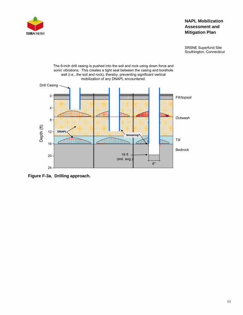
The 6-inch drill casing is pushed into the soil and rock using down force and sonic vibrations. This creates a tight seal between the casing and borehole
wall (i.e., the soil and rock), thereby, preventing significant vertical mobilization of any DNAPL encountered.
6”
Drill Casing
DNAPLSmearing?
19 ft(est. avg.)
Figure F-3a. Drilling approach.
12
NAPL Mobilization Assessment and Mitigation Plan
SRSNE Superfund Site Southington, Connecticut
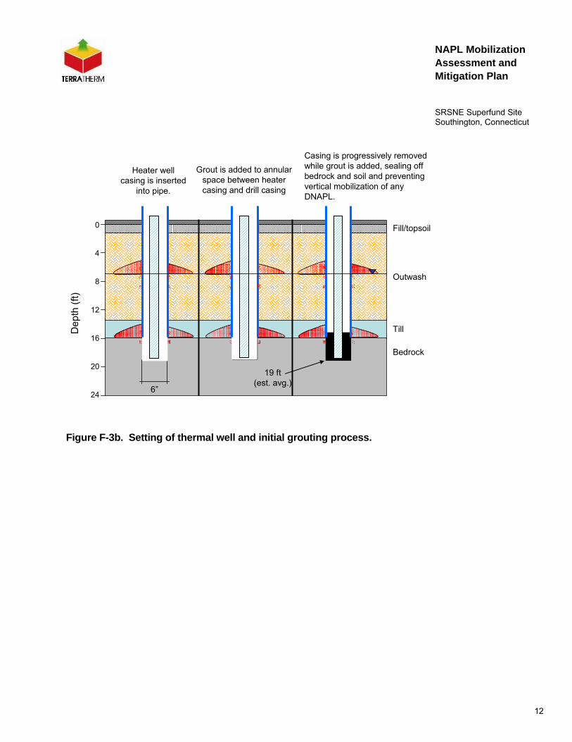
Figure F-3b. Setting of thermal well and initial grouting process.
Till
Outwash
Bedrock
Fill/topsoil0
4
8
12
16
20
24
Dep
th (f
t)
6”
Heater well casing is inserted
into pipe.
Grout is added to annular space between heater casing and drill casing
Casing is progressively removed while grout is added, sealing off bedrock and soil and preventing vertical mobilization of any DNAPL.
19 ft(est. avg.)

13
NAPL Mobilization Assessment and Mitigation Plan
SRSNE Superfund Site Southington, Connecticut
Till
Outwash
Bedrock
Fill/topsoil0
4
8
12
16
20
24
Dep
th (f
t)
6”
Casing is progressively removed while grout is added, sealing off bedrock and soil and preventing vertical
mobilization of any DNAPL.
19 ft(est. avg.)
Figure F-3c. Thermal well grouting and completion.
The temperature monitoring points and the combined vacuum/pressure and water level monitoring points will be installed using the same methods as proposed for the heater wells; however, the diameter of the cased hole for the temperature monitoring points will be smaller (3-4 inches).
The co-located vapor collector wells will also be installed using sonic drilling methods. However, the vapor collector wells will be installed to a total depth of approximately 8 ft and sand will be placed in the annular space corresponding with the screened section of the well. The sand will extend approximately 1 foot above the top of the well screen. Grout will be placed in the remaining annular space (0 to 1 ft bgs) to provide a surface seal.

14
NAPL Mobilization Assessment and Mitigation Plan
SRSNE Superfund Site Southington, Connecticut
In summary, none of the wells or borings used during the thermal remediation at the SRSNE Site will have a screen or a sand-pack that extends across the water table and into the bedrock. The TCH heater wells are comprised of solid steel casings which are grouted in place within a few minutes of drilling. The soil vapor extraction screens and the combined vacuum/pressure and water level monitoring screens will be installed to a depth of 12 ft, and not penetrate a significant distance into the saturated zone. Thermocouple monitoring borings will be metal pipes, grouted immediately upon installation.
The well installation procedures and designs selected for the SRSNE Site have been carefully developed to minimize the potential for NAPL to migrate during installation and construction to the extent practicable.

15
NAPL Mobilization Assessment and Mitigation Plan
SRSNE Superfund Site Southington, Connecticut
3. Assessment and Mitigation of DNAPL Mobilization During Heating and Operation
An essential part of any remedy is to ensure that the remedy itself does not make the problem worse. For NAPL source areas, and especially DNAPL source areas, the key challenge is to remove, and not spread, the DNAPL. At all previous Thermal Conduction Heating (TCH) sites, this has been prevented by proper design and precautions. In this section, the risk of unwanted DNAPL migration during heating and operation is discussed and the control methods that will be utilized to prevent unwanted mobilization at the SRSNE site are presented. This section also includes a review of relevant research on the properties and mechanisms affecting DNAPL mobilization,
3.1 Literature Review and Detailed Discussion of Properties and Mechanisms
The following provides a review of DNAPL behavior and thermal changes that occur during in-situ thermal remediation, TCH, with focus on the possibility of DNAPL pool removal and spreading.
A common question is what happens to DNAPL (pooled and residual) as it is heated? Exploration of this question would not be possible without the simple DNAPL science regarding DNAPL penetration of capillary barriers, or data on DNAPL property changes with temperature. Therefore, the most relevant properties and mechanisms are reviewed first, using TCE and PCE as example DNAPL constituents.
3.1.1 Eutectic Point: The Lower Boiling Point of a DNAPL-Water Mixture Areas with significant DNAPL will have lowered boiling points, due to the well-known eutectic point effects. The vapor pressures of two liquid phases located together equals the sum of the pure liquid vapor pressures, as illustrated in Figure F-4 below. This means that boiling will occur where water and DNAPL touch at temperatures below 100 C (73 C for TCE, 87 C for PCE; Davis 1997; Heron et al. 1998, DeVoe and Udell 1998). When the DNAPL has been fully vaporized, the temperature can increase to the boiling point of water. This mechanism is important for understanding what happens during subsurface heating where DNAPL is present either as residual or pools.

16
NAPL Mobilization Assessment and Mitigation Plan
SRSNE Superfund Site Southington, Connecticut
0.0
0.5
1.0
1.5
2.0
0 20 40 60 80 100
Temperature (oC)
Pres
sure
(atm
)
Water and TCE
Clean water
TCE
Figure F-4. Vapor pressure curves for water, TCE, and a zone where both are present.
3.1.2 Vertical Mobilization: Critical Pool Height and DNAPL Entry Through Capillary Barriers
Laboratory research has shown that heating can lead to decreases in interfacial tension and capillary entry pressures for PCE DNAPL (Sleep and Ma, 1997, Brown and Davis, 2007). Therefore, the potential for heating and field-scale ISTD to mobilize DNAPL needs to be addressed. To this effect, an analysis of the worst-case situation, where a significant thickness of DNAPL is prevented from migrating vertically by a capillary barrier, is in order. Following migration below the water table, DNAPL will tend to accumulate on top of low permeability layers or lenses. The maximum stable thickness of continuous DNAPL without penetrating a capillary barrier below the water table, also named the critical pool height, can be estimated by the following equation [Hunt et al. 1988; Mercer and Cohen 1990; Pankow and Cherry 1996]:
)(gr)cos(2z
wnfinern ρ−ρ⋅⋅
φ⋅σ⋅=
17
NAPL Mobilization Assessment and Mitigation Plan
SRSNE Superfund Site Southington, Connecticut
where σ: Interfacial tension (IFT) between the DNAPL and water [N/m] φ: Wetting contact angle [°] rfiner: Pore radii in the capillary barrier [m] g: Gravitational acceleration [m/s2] ρw: Density of water [kg/m3] ρn: Density of DNAPL [kg/m3]
Note that the viscosity of the DNAPL or the water does not enter into this equation. Factors that may affect DNAPL mobility (i.e., ability to penetrate a capillary barrier) include changes in interfacial tension (IFT), contact angle, or density. Also note that decreases in IFT will result in a decrease in the critical pool height that a capillary barrier can support. Increase in the contact angle would lead to an increased critical pool height.
Thus, for a DNAPL pool with a thickness equal to the maximum stable pool height, a decrease in IFT or increase in the contact angle could result in the DNAPL pool penetrating the barrier and downward migration of the DNAPL. On the other hand, if the density of the DNAPL decreases more than the density of water decreases (i.e., there is a net increase in the buoyancy of the DNAPL), then the downward driving force decreases [g x (ρn-ρw)] and the critical pool height increases, leading to increased stabilization of the DNAPL pool. Sleep and Ma (1997) and Brown and Davis (2007) measured the interfacial tension of PCE-water as a function of temperature (Figure F-5). The change is less than 10% between 10 and 87 ºC, where PCE would boil.
As shown by Heron et al (1998) and Brown and Davis (2007) and in Figure F-5, DNAPL swelling (i.e., thermal expansion) during heating will tend to reduce the density difference between DNAPL and water, and therefore stabilize the situation by increasing the maximum stable pool height.
Figure F-5 also contains the calculated critical pool height based on the IFT and density data, assuming that the contact angle stays the same. This shows that the critical pool height may increase with temperature, leading to a more stable condition (as much as 12% increase from 10 to 100 ºC). No data exist for the contact angle change with temperature, but observation in laboratory setups do not indicate a significant change (PCE behavior has been observed to be stable in porous media during heating, until the eutectic point is reached, at which it will boil; Udell 2004).

18
NAPL Mobilization Assessment and Mitigation Plan
SRSNE Superfund Site Southington, Connecticut
Figure F-5. Temperature dependency of interfacial tension for a PCE-water system (Sleep and Ma, 1997; Brown and Davis, 2007) and the difference in density between PCE DNAPL and water (modified from Heron et al. 1998), and the calculated critical pool height relative to ambient temperature (assuming constant contact angle).
In conclusion, the analysis shows that the changes in chemical properties for a typical DNAPL constituent do not significantly affect the maximum stable pool height that a capillary barrier can support and thus do not result in an appreciable increase in the risk of vertical mobilization of a pool. In fact, if the contact angle is unaffected, a raise in temperature will lead to a more stable DNAPL condition. These concepts are summarized in Figure F-5.
0
0.2
0.4
0.6
0.8
1
1.2
1.4
0 20 40 60 80 100
Temperature (oC)
Rel
ativ
e cr
itica
l poo
l hei
ght a
nd
dens
ity d
iffer
ence
(g/m
L)
0
10
20
30
40
50
Inte
rfaci
al te
nsio
n (d
yn/c
m)
IFT
Relative critical pool height
Density difference PCE-water

19
NAPL Mobilization Assessment and Mitigation Plan
SRSNE Superfund Site Southington, Connecticut
3.1.3 Rate of Heating of DNAPL Pools Relative to Surrounding Material
The heating rate depends on thermal conduction from the heater wells and convection of steam. A DNAPL-saturated porous medium will have an overall thermal conductivity and heat capacity which is similar to a water-saturated medium (K between 1.5 and 2.5 W/m/K and C in the range of 700-1,000 J/kg/K). The thermal properties of common DNAPL constituents (chlorinated solvents, coal tar, PCB) are not dramatically different than those of water. If the volume of DNAPL is substantial, it will be vaporized and removed at temperatures close to the eutectic point, which are lower than the boiling point of water. Therefore, temperature gradients will be higher towards such areas, allowing heat conduction to occur at least as fast as it does in the surrounding water-filled medium. While this boiling leads to lower temperatures in areas containing DNAPL, the time is used to vaporize the bulk of the DNAPL mass; therefore, it is not a hindrance to the effectiveness of the remedy but a critical component ensuring attainment of the remedial goals (Figure F-6).
In summary, there is no reason to believe that heating will be significantly slower or inhibited in subsurface zones containing high DNAPL saturations, or pools.

20
NAPL Mobilization Assessment and Mitigation Plan
SRSNE Superfund Site Southington, Connecticut
Boiling atDNAPL/Water
Interface
100oC
EutecticPoint
Removal ofPools/Residual
DNAPL
Removal ofDissolved/
Sorbed Mass
Water Boiling Steam Stripping
Volatilization
Critical Pool Height Necessary to Penetrate Capillary Barrier
IFT ⇓
DNAPL Buoyancy⇑
Temperature/Time
Time
Tem
pera
ture
Moderate decreases in IFT are off-set by the thermal expansion of the DNAPL (increased buoyancy), thus the Critical Pool Height does not change appreciably and the risk of vertical mobilization is minimal.
Figure F-6. DNAPL behavior as a function of time and temperature at the edge of a DNAPL pool nearest a thermal conduction heater.
3.1.4 Removal of DNAPL Pools and Risk for Vertical Mobilization
The fundamental physical/chemical changes and behaviors of DNAPL during heating were discussed above. What follows is a discussion of how ISTD/TCH ensures efficient and effective removal of DNAPL pools and minimizes the risk of vertical mobilization.

21
NAPL Mobilization Assessment and Mitigation Plan
SRSNE Superfund Site Southington, Connecticut
DNAPL present in the treatment zone will eventually be boiled and vaporized and removed from the subsurface via the heater-vacuum wells as the pools are heated from the sides, and vapors are generated and travel towards low-pressure locations. Modest decreases in IFT are not enough to result in vertical pool mobilization. Furthermore, because the entire treatment zone is kept under a vacuum and the steam and contaminant vapors are extracted from the subsurface simultaneously with the heating, condensation of the steam and contaminants is minimized. This prevents the formation of significant DNAPL condensation banks, thus reducing the potential for vertical mobilization.
Furthermore, it is difficult to imagine a physical situation where the risk of downward migration is increased significantly due to the modest changes in DNAPL characteristics during heating as compared to naturally occurring historical perturbations such as severe storm events with rapid infiltration or significant changes in horizontal and vertical hydraulic gradients. For example, air entrapment beneath an infiltration front can result in significant pressure increases (10 to 20 inches of water) below the water table and hydraulic gradients can fluctuate by several feet or more due to seasonal variation and anthropogenic causes (Freeze and Cherry, 1979). Potential for DNAPL Condensation in Unwanted Locations
When DNAPL pools are vaporized, the vapors (steam and COCs mixed) can migrate into cooler zones and condense. Since vapors have significant buoyancy compared to the groundwater, they will tend to migrate upwards or directly towards low pressure points such as the extraction wells. However, situations exist where the vapors travel to zones cooler than the eutectic temperature, in which they can condense. This is accounted for in the ISTD design by the following:
1. Surround the treatment zone with heaters: Heating of a clean zone around the perimeter surrounds the treatment zone with heated soils that are too hot to allow DNAPL migration or condensation outside the target zone.
2. Heat thoroughly to the surface: For this project, heating will progress to the land surface, and a vapor barrier and insulation layer will ensure that no cold zones exist in the vadose zone.

22
NAPL Mobilization Assessment and Mitigation Plan
SRSNE Superfund Site Southington, Connecticut
In conclusion, while zones of DNAPL condensate can form in locations that are below the eutectic temperature, these zones will be inside the target treatment zone, and eventually the entire zone will be heated to temperatures too high for the condensate to stay. The thermal remediation system planned for the SRSNE site incorporates these approaches. This will minimize the risk of unwanted mobilization of DNAPL outside or below the treatment zone.
3.2 Summary of DNAPL Mobilization Risk During Heating/Operation
As summarized above and discussed in the White Paper for Thermal Technologies prepared for the SRSNE Superfund Site Feasibility Study (see Appendix V of the FS), TCH does not create conditions favorable for vertical mobilization due to the following:
• NAPL becomes more buoyant due to differential thermal expansion. The density of DNAPL with a high percentage of chlorinated hydrocarbons decreases at a faster rate than the density of water when heated. The net result is that the DNAPL becomes more buoyant relative to the water as it is heated and the driving gravitational force becomes less. Thus, the capillary pressure of a DNAPL pool overlying a capillary barrier (e.g., silt lens or bedrock fracture) becomes less as it heats, and the pool becomes more stable.
• Although the interfacial tension of chlorinated hydrocarbons decreases as the temperature increases (thus possibly making DNAPL pools less stable), the magnitude of the decrease is small relative to the increase in buoyancy of the DNAPL and the net change in the capillary force balance of the DNAPL and the barrier is negative, resulting in an increase in pool stability with heating.
In addition, as also described in the White Paper for Thermal Technologies, thermal treatment using TCH results in the progressive depletion of DNAPL zones due to incremental increases in subsurface temperatures during heating. This concept is illustrated in Figure F-7.
23
NAPL Mobilization Assessment and Mitigation Plan
SRSNE Superfund Site Southington, Connecticut
Till
Outwash
Bedrock
Fill/topsoil0
4
8
12
16
20
24
Dep
th (f
t)
6”
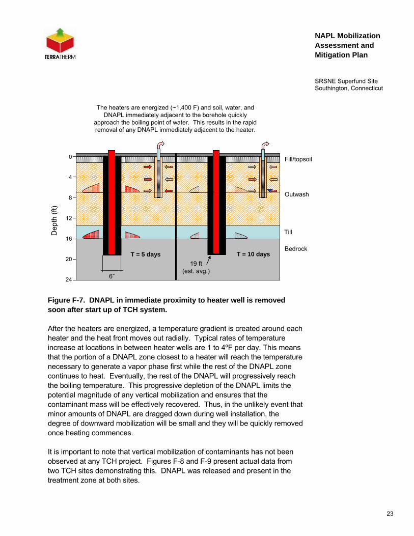
The heaters are energized (~1,400 F) and soil, water, and DNAPL immediately adjacent to the borehole quickly
approach the boiling point of water. This results in the rapid removal of any DNAPL immediately adjacent to the heater.
T = 5 days T = 10 days19 ft
(est. avg.)
Figure F-7. DNAPL in immediate proximity to heater well is removed soon after start up of TCH system.
After the heaters are energized, a temperature gradient is created around each heater and the heat front moves out radially. Typical rates of temperature increase at locations in between heater wells are 1 to 4ºF per day. This means that the portion of a DNAPL zone closest to a heater will reach the temperature necessary to generate a vapor phase first while the rest of the DNAPL zone continues to heat. Eventually, the rest of the DNAPL will progressively reach the boiling temperature. This progressive depletion of the DNAPL limits the potential magnitude of any vertical mobilization and ensures that the contaminant mass will be effectively recovered. Thus, in the unlikely event that minor amounts of DNAPL are dragged down during well installation, the degree of downward mobilization will be small and they will be quickly removed once heating commences.
It is important to note that vertical mobilization of contaminants has not been observed at any TCH project. Figures F-8 and F-9 present actual data from two TCH sites demonstrating this. DNAPL was released and present in the treatment zone at both sites.

24
NAPL Mobilization Assessment and Mitigation Plan
SRSNE Superfund Site Southington, Connecticut
For the first site, shown in Figure F-8, the DNAPL was pure TCE and the treatment zone extended to a depth of 90 feet and included weathered and fractured bedrock (55 to 90 ft). Although pre-treatment sampling had detected DNAPL, post treatment sampling (56 samples) indicated that there was no vertical mobilization (i.e., no increase in concentrations at depth). Maximum concentrations were reduced by over 5 orders of magnitude (99.999% reduction) and the post-treatment mean concentration within the treatment zone based on 56 samples was 11 μg/kg (the 95% UCL of the mean was 17.1 μg/kg).
0
10
20
30
40
50
60
70
80
90
1 10 100 1,000 10,000 100,000 1,000,000 10,000,000 100,000,000
Location 1
Location 2
Location 3
Location 4
Location 5
Location 6
MaxPre-Treatment
ft bg
s
ND DNAPLCleanup Objective: 95% UCL of mean < 60 μg.kg
Min. Soil Conc.indicative of DNAPL;
foc: 0.05% - 0.1%n: 0.3-0.35
95% UCL of mean TCE conc. = 17.1 μg/kg
Soil TCE Concentration (μg/kg)
Figure F-8. Comparison of starting and post treatment soil concentrations at a TCH site in SC demonstrating no downward mobilization of DNAPL (Heron et al, 2008).

25
NAPL Mobilization Assessment and Mitigation Plan
SRSNE Superfund Site Southington, Connecticut
At the second site, shown in Figure F-9, the DNAPL was a mixture of chemicals including PCE. The treatment zone extended to 20 ft and consisted primarily of clay. A similar pattern to what was observed at the SC site was also observed at the Richmond, CA site: there was no increase in concentrations at the bottom of the treatment zone or evidence of vertical mobilization.
0
1
2
3
4
5
6
7
8
0 1 10 100 1,000 10,000 100,000 1,000,000 10,000,000
Soil Concentration - μg/kg
Dep
th B
elow
Gro
und
Surf
ace
- m
Pretreatment - PCEPost Treatment - PCE
Bottom of Treatment Zone
Bottom of Heated Zone
Soil PCE Concentration (μg/kg)
Figure F-9. Comparison of starting and post treatment soil concentrations at a TCH site in Richmond, CA demonstrating no downward mobilization of DNAPL (Davis, et al, 2006).
These data show that there is a very low risk of mobilizing DNAPL pools during the thermal treatment at SRSNE, if the thermal design carefully accounts for the physics of the subsurface and the contaminant properties. Small changes in interfacial tension and density with temperature indicate that the critical pool height does not change significantly. Furthermore, preferential boiling at the DNAPL-water interfaces leads to pool vaporization and shrinking during heat-up.

26
NAPL Mobilization Assessment and Mitigation Plan
SRSNE Superfund Site Southington, Connecticut
Independent EPA-led publications support the small risk of vertical mobilization during thermal remediation (Brown and Davis, 2007; Davis et al. 2007). The authors reviewed critical NAPL property changes with temperature and examined field data from thermal projects. No indications of downward NAPL migration were observed.
The present knowledge of DNAPL behavior during heating has been properly included in TCH design and operational practices, making it very unlikely that DNAPL pools will penetrate deeper during remediation. DNAPL condensation will be temporary in zones that are eventually heated and treated. At the SRSNE Site, a robust vapor treatment design will be used to be prepared for periods with high mass recovery.

27
NAPL Mobilization Assessment and Mitigation Plan
SRSNE Superfund Site Southington, Connecticut
4. DNAPL Migration Monitoring and Mitigation
Since DNAPL may already be present in some areas below the target treatment area, and since the downgradient area is within the contaminated NTCRA containment zone, monitoring for DNAPL migration is very challenging at the SRSNE Site
The 8 overburden "N" wells located downgradient of the thermal treatment zone and upgradient of the NTCRA containment system, as shown on Figures N-2 through N-4 of the Monitoring Well Network Evaluation and Groundwater Monitoring Program (Attachment N to the RDWP), will be monitored for evidence of DNAPL migration. All the “N” wells will be gauged for DNAPL before the onset of drilling activities associated with the installation of the thermal system, and therefore before heating is initiated. During and following heating the wells will be monitored at least once per week for temperature and NAPL presence. If NAPL is observed within any of the “N” wells, it will be removed immediately using a bailer and/or appropriate pump.

28
NAPL Mobilization Assessment and Mitigation Plan
SRSNE Superfund Site Southington, Connecticut
5. References
Brown, J., E. L. Davis. 2007. “Does Increasing the Temperature Induce DNAPL Mobilization?” Poster paper presented at McNair Scholars Internship Program, East Central University, Ada, OK.
Davis, E. L. 1997. “How Heat Can Accelerate In-situ Soil and Aquifer Remediation: Important Chemical Properties and Guidance on Choosing the Appropriate Technique.” US EPA Issue paper, EPA/540/S-97/502.
Davis, E.L., G. Heron and J. LaChance. 2006. “Does Field Data Show Downward Mobilization of DNAPL during Thermal Treatment?” Poster paper presented at Remediation of Chlorinated and Recalcitrant Compounds—2006. Fifth International Conference on Remediation of Chlorinated and Recalcitrant Compounds (Monterey, CA; May 2006).
DeVoe, C., and K.S. Udell. 1998. “Thermodynamic and Hydrodynamic behaviour of water and DNAPLs during heating.” In Proceedings from the First Conference on Remediation of Chlorinated and Recalcitrant Compounds, May 18-21, Monterey CA, Battelle Press 1 (2): 61-66.
Freeze, R.A., J.A. Cherry. 1979. Groundwater. Prentice-Hall, NJ. ISBN 0-13-365312-9.
Heron, G., T. H. Christensen, T. Heron and T. H. Larsen. 1998. “Thermally enhanced remediation at DNAPL Sites: The Competition between Downward Mobilization and Upward Volatilization.” Paper presented at the 1st International Conference on Remediation of Chlorinated and Recalcitrant Compounds, Monterey, California, May 18-21.
Heron, G., R.S. Baker, J.M. Bierschenk, and J.C. LaChance. 2008. “Use of Thermal Conduction Heating for the Remediation of DNAPL in Fractured Bedrock.” Remediation of Chlorinated and Recalcitrant Compounds—2008. Proceedings of the Sixth International Conference on Remediation of Chlorinated and Recalcitrant Compounds (Monterey, CA; May 2008). Battelle Press, Columbus, OH.
Hunt, J.R., N. Sitar, and K.S. Udell. 1988. “Nonaqueous phase liquid transport and cleanup 1. Analysis of mechanisms.” Water Resources Research, 24, no. 8: 1247-1258.

29
NAPL Mobilization Assessment and Mitigation Plan
SRSNE Superfund Site Southington, Connecticut
Mercer, J.W., and R.M. Cohen. 1990. “A review of immiscible fluids in the subsurface: properties, models, characterization and remediation.” Journal of Contaminant Hydrology, 6: 107-163.
Pankow, J.F., and J.A. Cherry. 1996. Dense Chlorinated Solvents and Other DNAPLs in Groundwater: History, Behavior, and Remediation. Waterloo Press. ISBN 0-9648014-1-8.
Sleep, Brent E. and Yanfang Ma. 1997. “Thermal Variation of Organic Fluid Properties and Impact on Thermal Remediation Feasibility.” Journal of Soil Contamination, 6 (3).
Udell, K.S. 2004. “Mechanisms of Thermal Remediation.” Platform presentation at the Fourth Conference on Chlorinated and Recalcitrant Compounds, Monterey, California, May 24-27.


![[NAPL Owners Conference 2011] Print + Mobile: Understanding QR Codes](https://static.fdocuments.in/doc/165x107/5554cec1b4c9051b6e8b482a/napl-owners-conference-2011-print-mobile-understanding-qr-codes.jpg)