Naist2015 dec ver1
70
A Digital Spectrometer on a Radio Telescope, and its Realization on FPGAs Hiroki Nakahara Ehime University
-
Upload
hiroki-nakahara -
Category
Engineering
-
view
1.378 -
download
1
Transcript of Naist2015 dec ver1
A Digital Spectrometer on a Radio Telescope,
and its Realization on FPGAsHiroki NakaharaEhime University
Outline
• Introduction• Digital spectrometer for a radio telescope
• ROACH system at Oxford University• Realization on the FPGA
• Nested residue number system (Nested RNS)• Implementation
• Future plans• Conclusion

Ehime University
・KU
KIT・ ・
EU
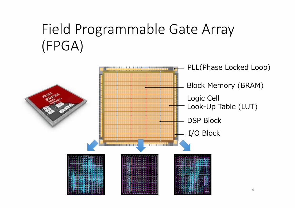
Field Programmable Gate Array (FPGA)
4
PLL(Phase Locked Loop)
Block Memory (BRAM)Logic CellLook-Up Table (LUT)
DSP Block I/O Block
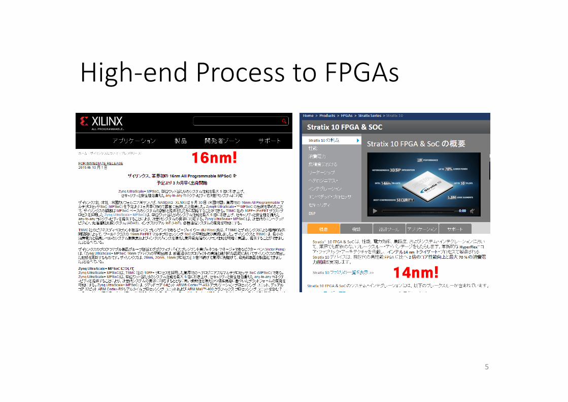
High‐end Process to FPGAs
5
16nm!
14nm!
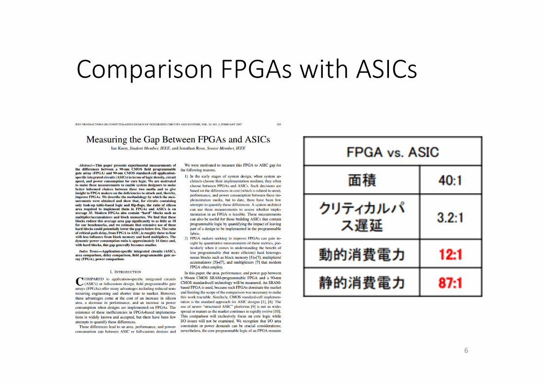
Comparison FPGAs with ASICs
6
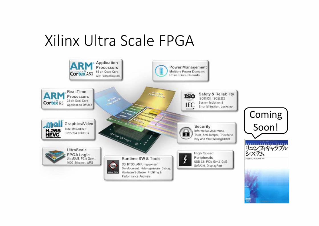
Xilinx Ultra Scale FPGA
ComingSoon!
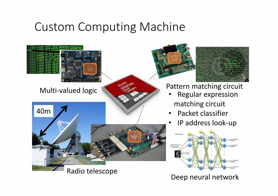
Custom Computing Machine
8
Multi‐valued logic Pattern matching circuit• Regular expressionmatching circuit
• Packet classifier• IP address look‐up
40m
Radio telescopeDeep neural network
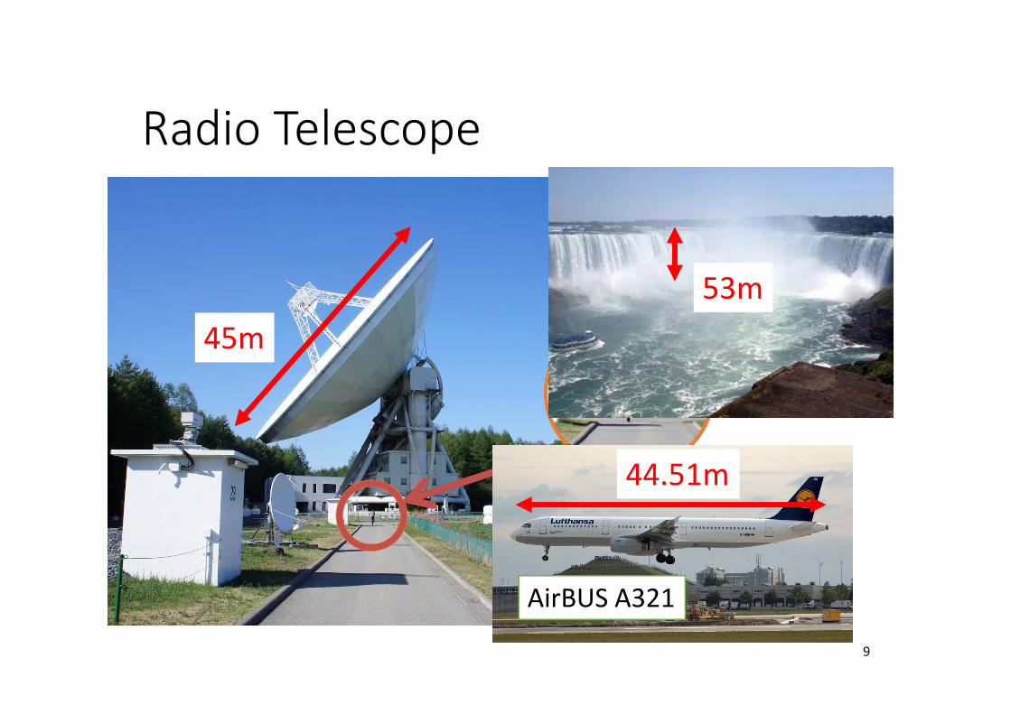
Radio Telescope
9
45m
AirBUS A321
44.51m
53m
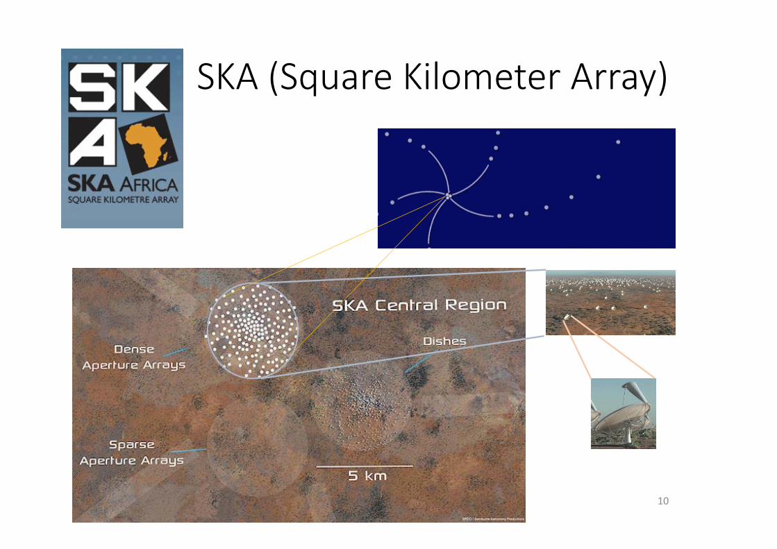
SKA (Square Kilometer Array)
10
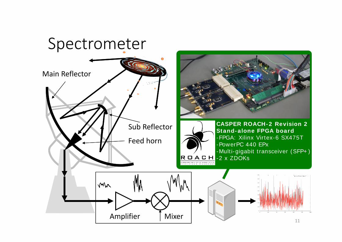
Spectrometer
Feed horn
Amplifier Mixer
CASPER ROACH-2 Revision 2Stand-alone FPGA board-FPGA: Xilinx Virtex-6 SX475T-PowerPC 440 EPx-Multi-gigabit transceiver (SFP+)-2 x ZDOKs
11
Sub Reflector
Main Reflector
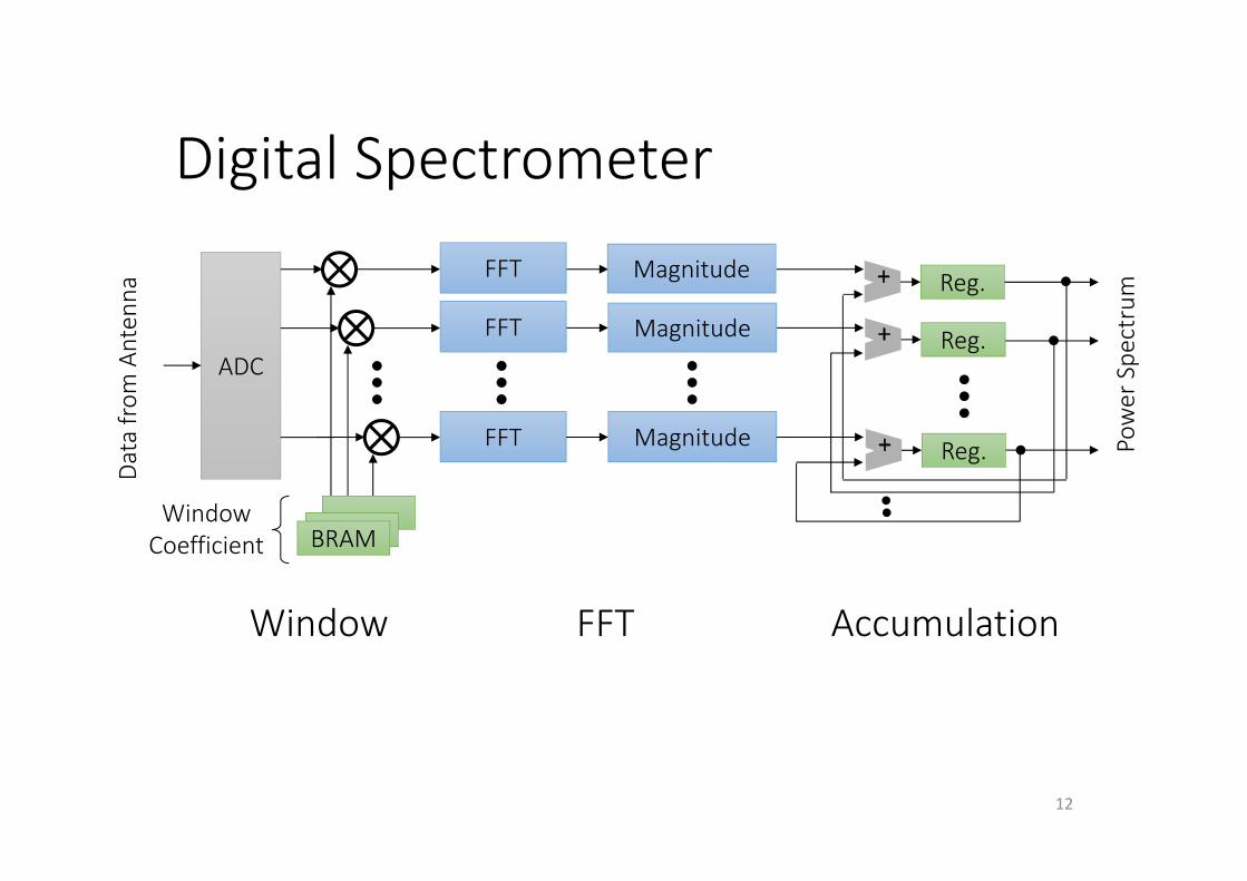
Digital Spectrometer
12
ADC
BRAM
FFT Magnitude
WindowCoefficient
Data from
Antenna
Power Spe
ctrum
FFT
FFT
Magnitude
Magnitude + Reg.
+ Reg.
+ Reg.
Window FFT Accumulation
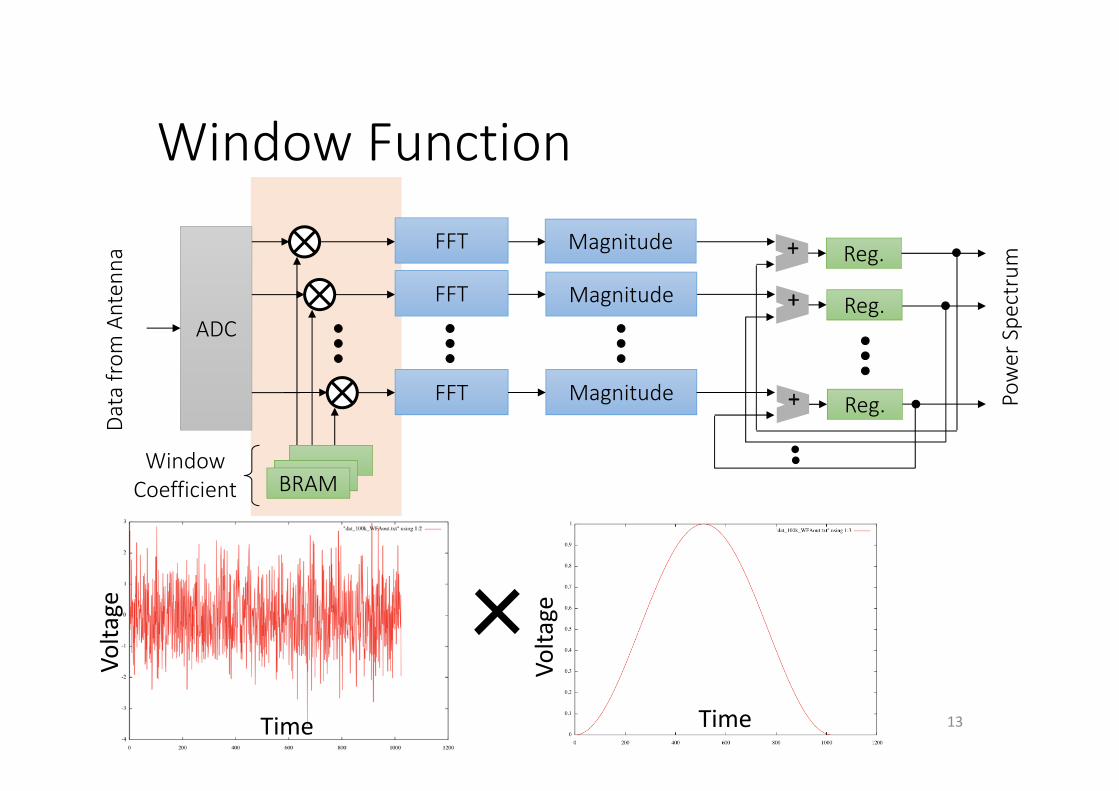
Window Function
13
ADC
BRAM
FFT Magnitude
WindowCoefficient
Data from
Antenna
Power Spe
ctrum
FFT
FFT
Magnitude
Magnitude + Reg.
+ Reg.
+ Reg.
×
Volta
ge
Volta
ge
Time Time
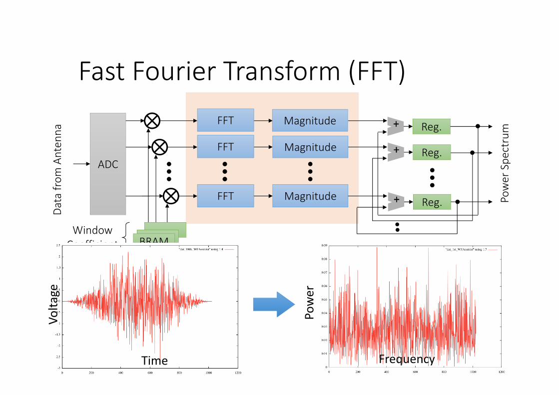
Fast Fourier Transform (FFT)
14
ADC
BRAM
FFT Magnitude
WindowCoefficient
Data from
Antenna
Power Spe
ctrum
FFT
FFT
Magnitude
Magnitude + Reg.
+ Reg.
+ Reg.
Time Frequency
Volta
ge
Power
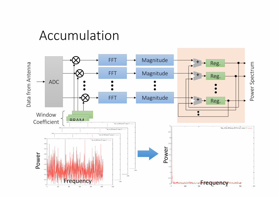
Accumulation
15
ADC
BRAM
FFT Magnitude
WindowCoefficient
Data from
Antenna
Power Spe
ctrum
FFT
FFT
Magnitude
Magnitude + Reg.
+ Reg.
+ Reg.
15Frequency
Power
Power
Frequency
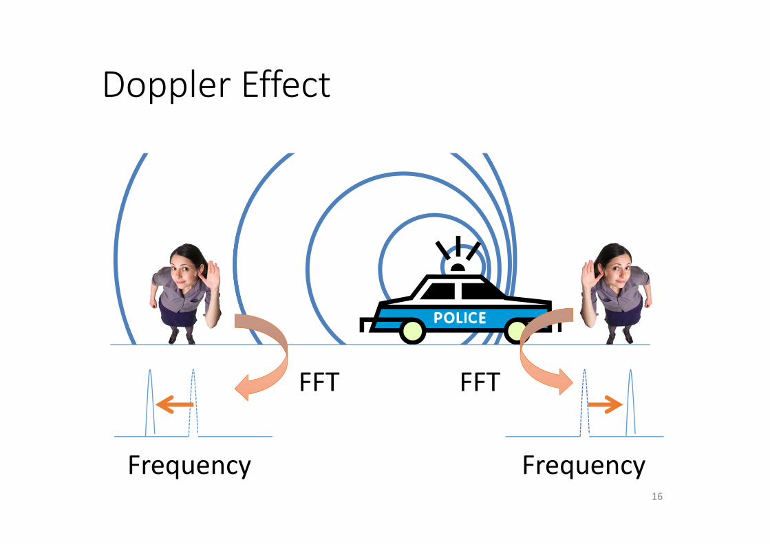
Doppler Effect
16
FFT FFT
Frequency Frequency
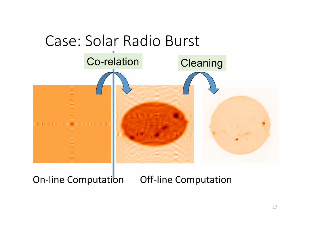
Case: Solar Radio Burst
17
Co-relation Cleaning
On‐line Computation Off‐line Computation
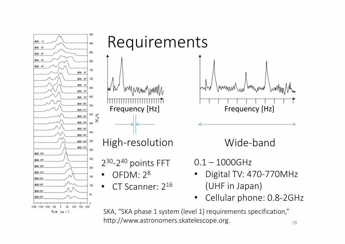
Requirements
18
Wide‐bandHigh‐resolution
230‐240 points FFT• OFDM: 28• CT Scanner: 216
0.1 – 1000GHz• Digital TV: 470‐770MHz
(UHF in Japan)• Cellular phone: 0.8‐2GHz
Frequency [Hz] Frequency [Hz]
SKA, “SKA phase 1 system (level 1) requirements specification,”http://www.astronomers.skatelescope.org.
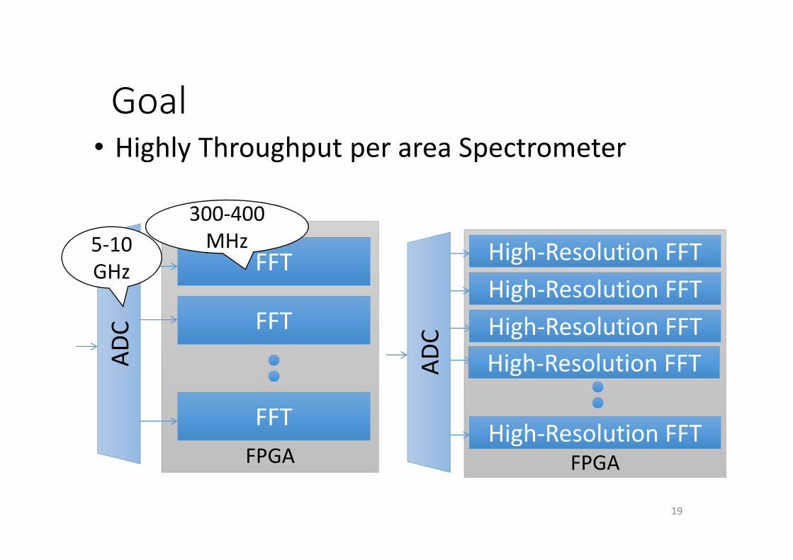
Goal
19
FPGA FPGA
FFT
FFT
FFT
High‐Resolution FFTHigh‐Resolution FFTHigh‐Resolution FFT
High‐Resolution FFT
• Highly Throughput per area SpectrometerAD
C
5‐10GHz
300‐400MHz
High‐Resolution FFTADC
Outline
• Introduction• Digital spectrometer for a radio telescope
• ROACH system at Oxford University• Realization on the FPGA
• Nested residue number system (Nested RNS)• Implementation
• Future plans• Conclusion
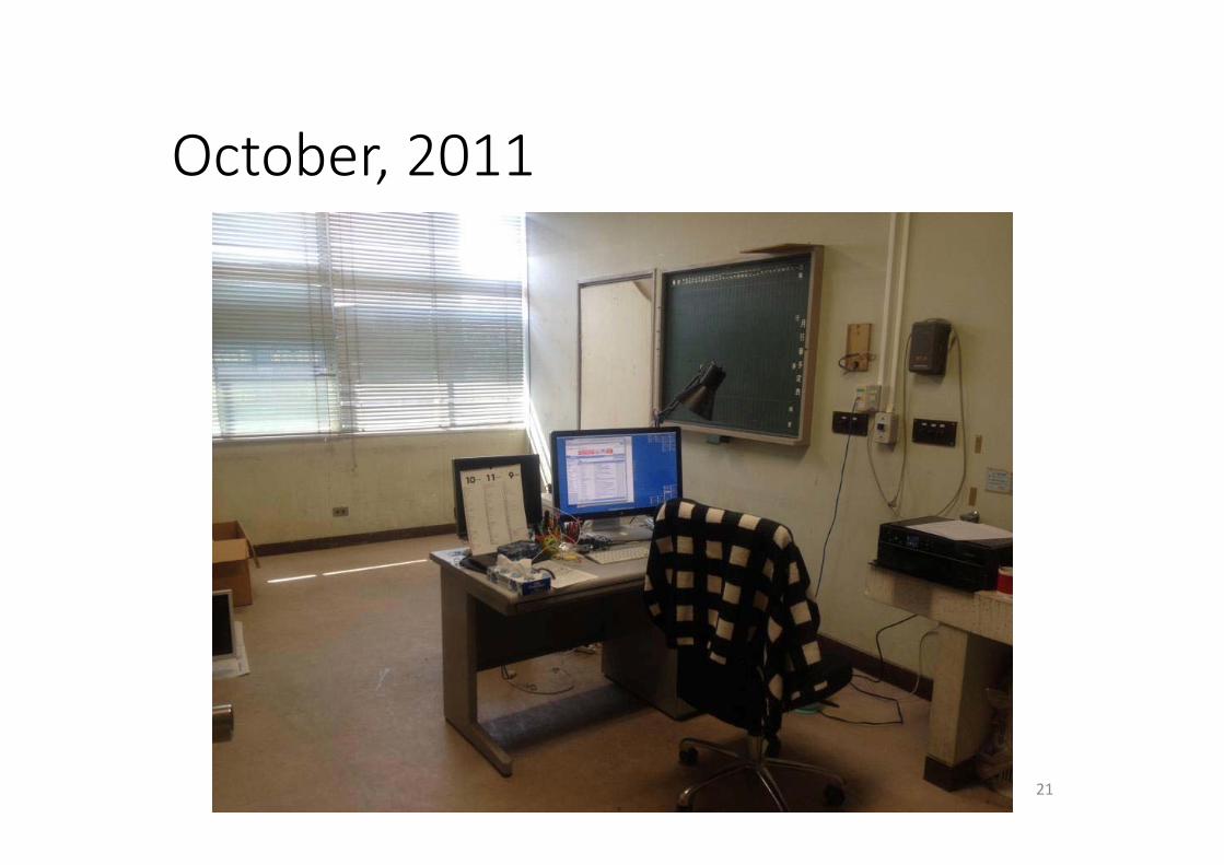
October, 2011
21

Oxford University
22

Sightseeing at Oxford
23
Quiz
24

Discussion with Prof. Nakanishi
25
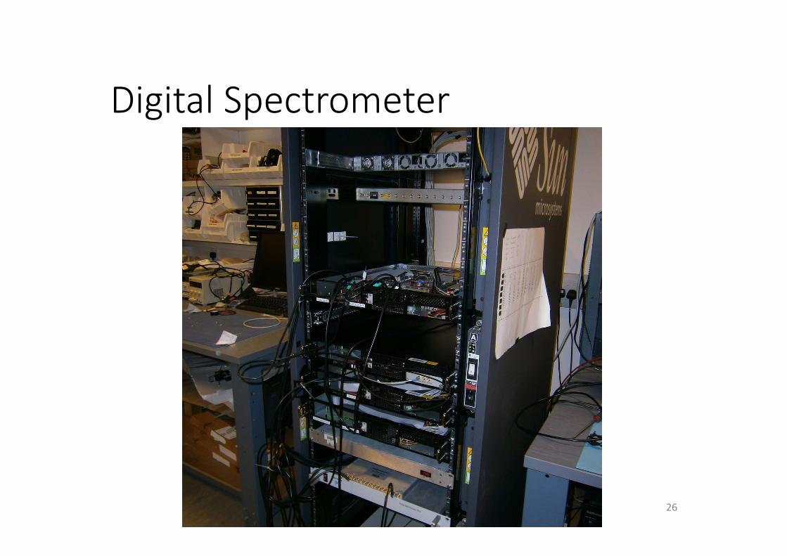
Digital Spectrometer
26
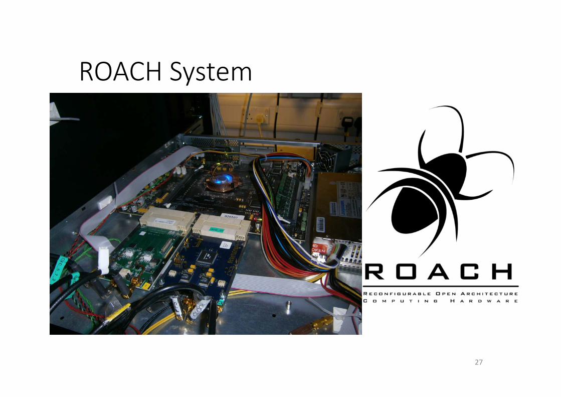
ROACH System
27
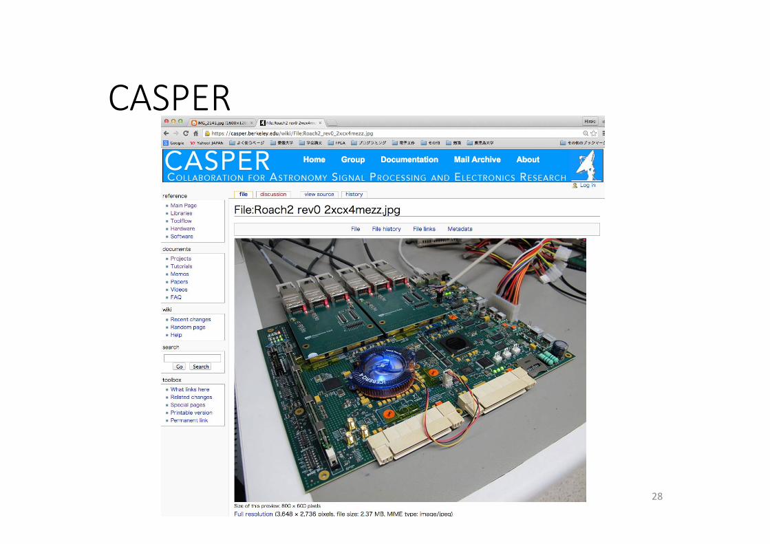
CASPER
28

Dinner...but,
29
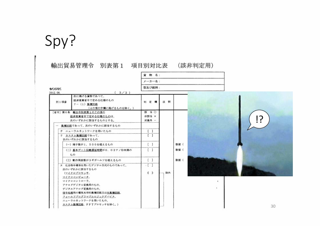
Spy?
30
!?
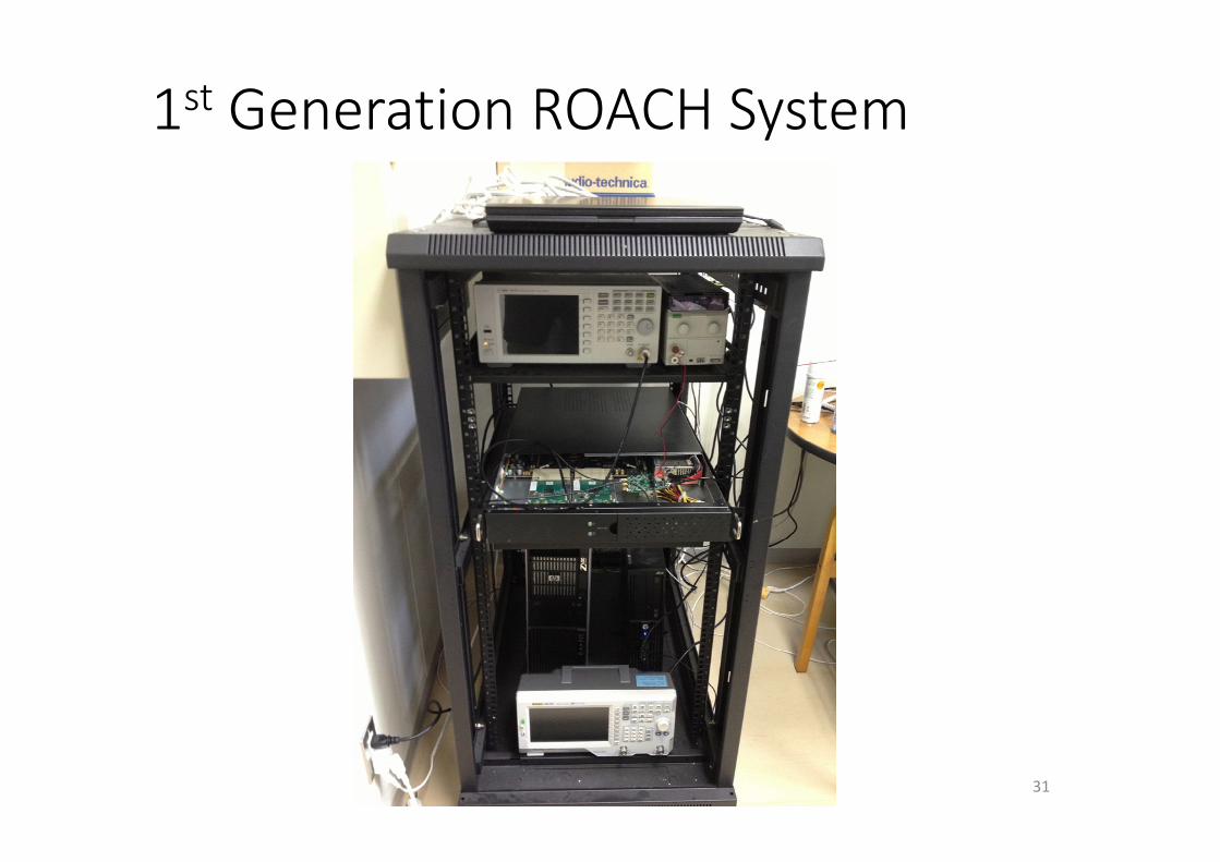
1st Generation ROACH System
31
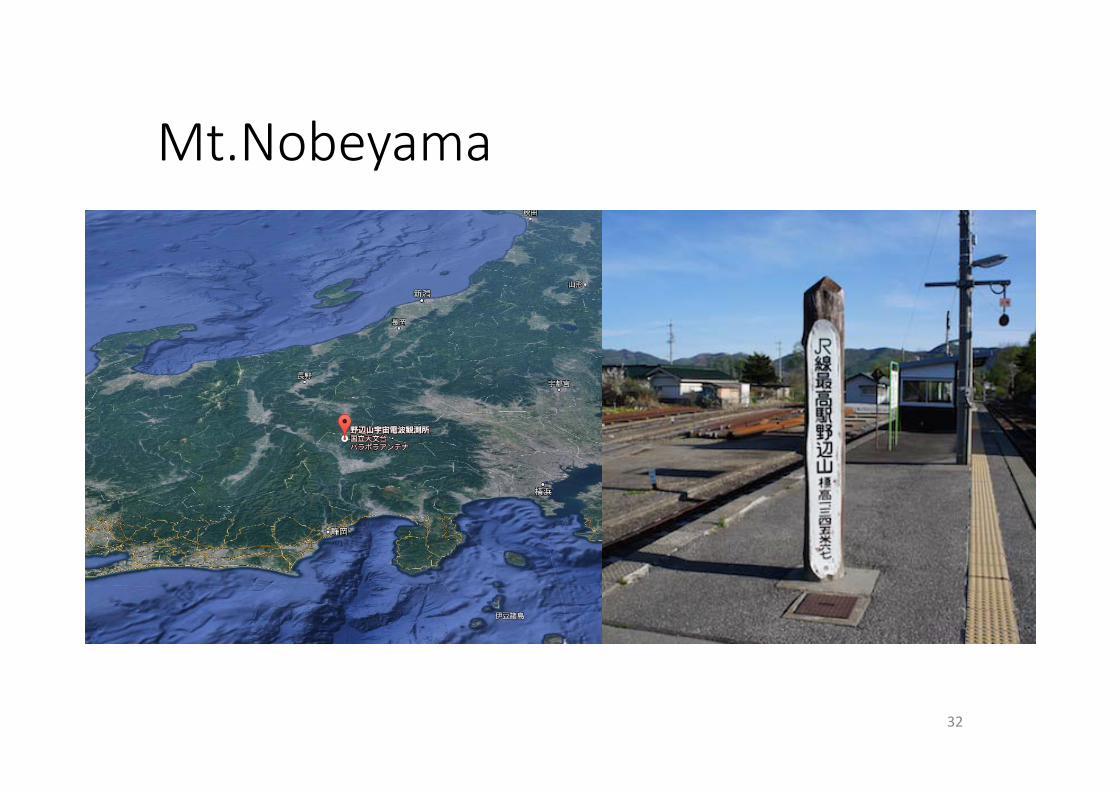
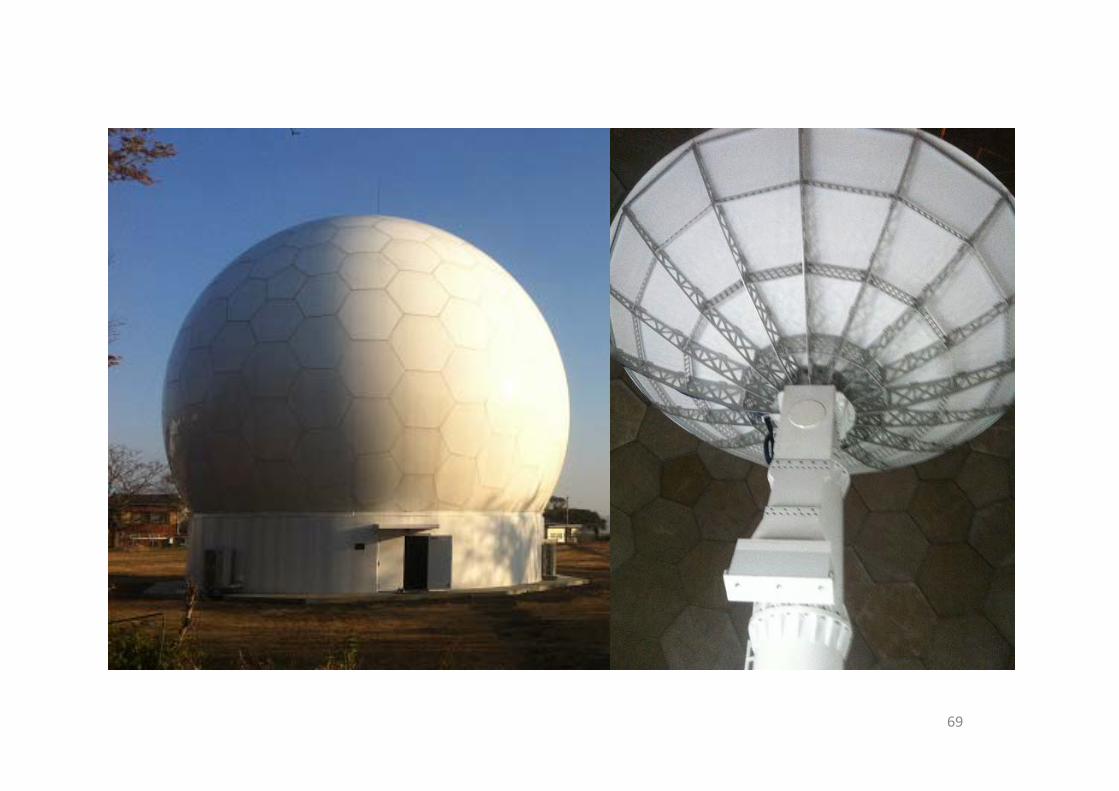
Mt.Nobeyama
32
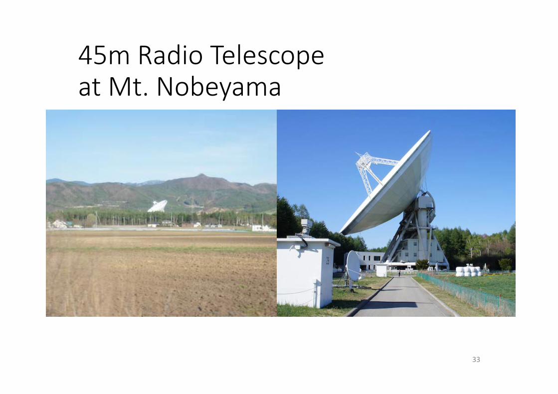
45m Radio Telescopeat Mt. Nobeyama
33
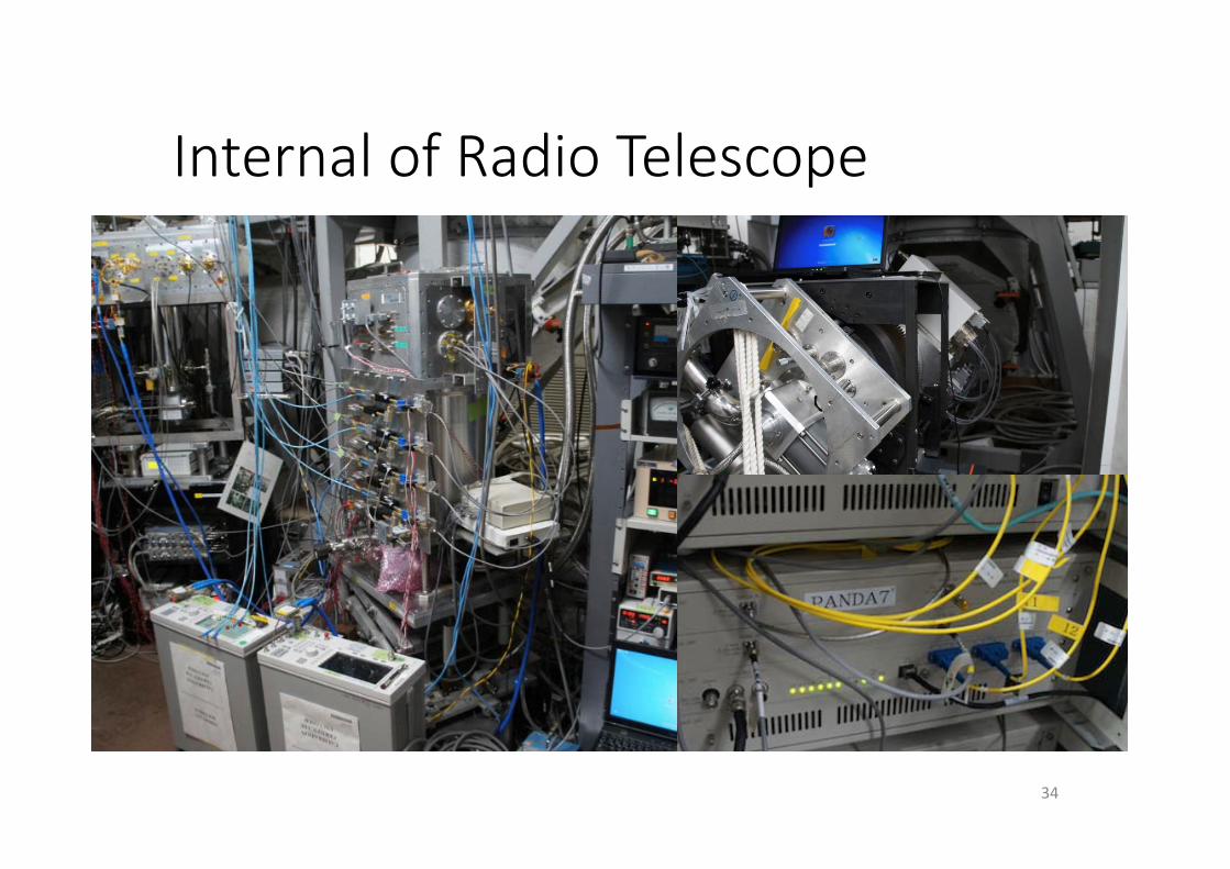
Internal of Radio Telescope
34
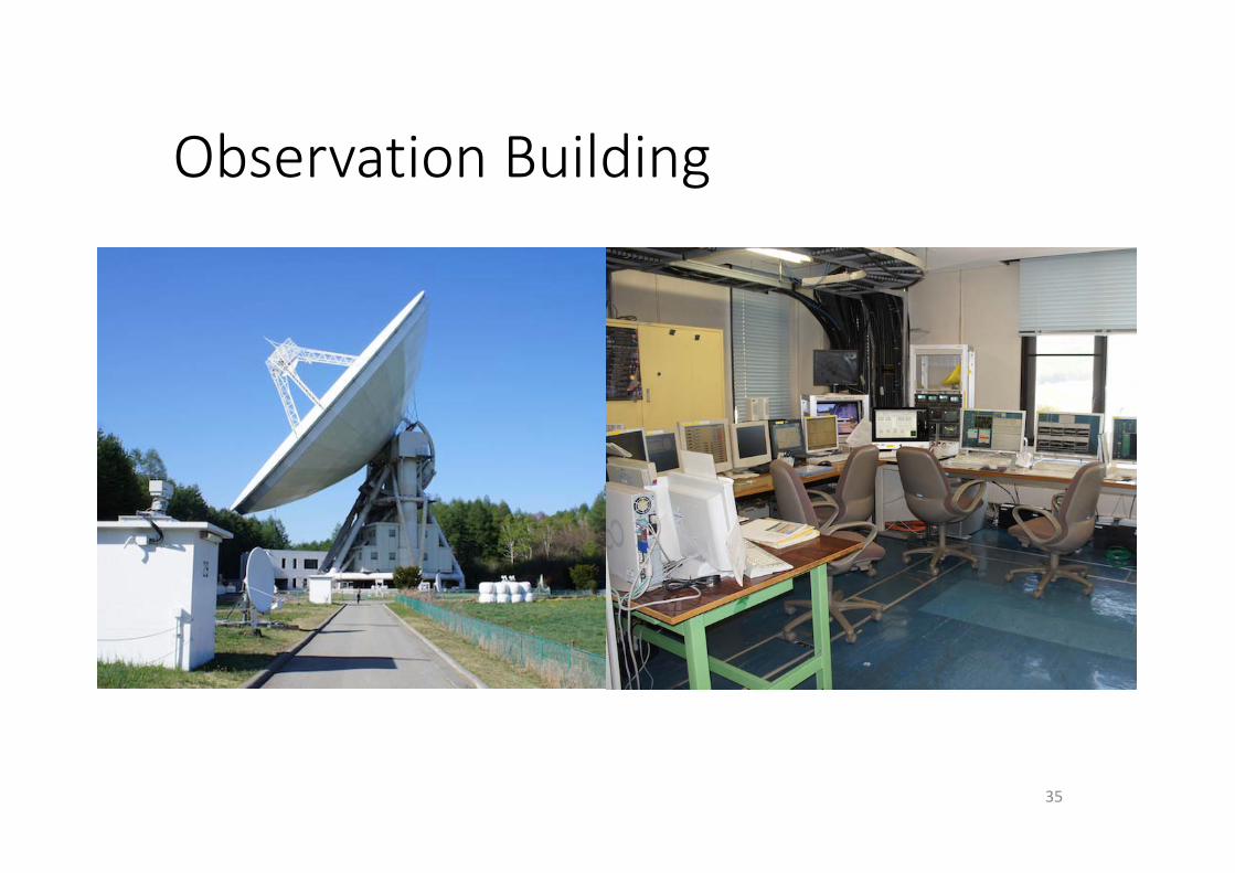
Observation Building
35
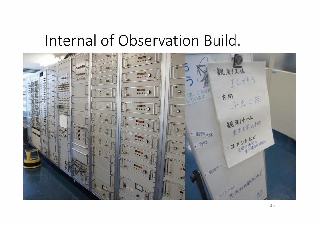
Internal of Observation Build.
36
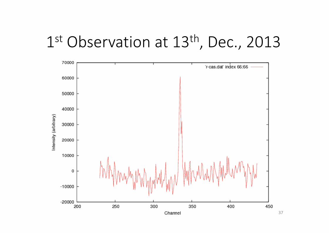
1st Observation at 13th, Dec., 2013
37
Outline
• Introduction• Digital spectrometer for a radio telescope
• ROACH system at Oxford University• Realization Highly Throughput/Area on the FPGA
• Nested residue number system (Nested RNS)• Implementation
• Future plans• Conclusion
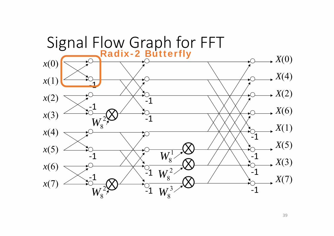
Signal Flow Graph for FFT
39
x(0)
x(1)
x(2)
x(3)
x(4)
x(5)
x(6)
x(7)
X(0)
X(4)
X(2)
X(6)
X(1)
X(5)
X(3)
X(7)2
8W
28W
18W2
8W3
8W
‐1
‐1
‐1
‐1
‐1
‐1
‐1
‐1
‐1
‐1
‐1
‐1
Radix-2 Butterfly
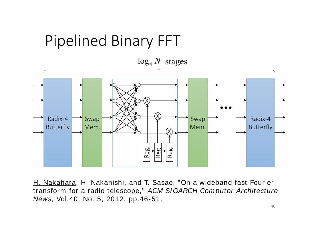
Pipelined Binary FFT
40
Radix‐4Butterfly
SwapMem.
Radix‐4Butterfly
SwapMem.
N4log stages
Reg.
Reg.
Reg.
H. Nakahara, H. Nakanishi, and T. Sasao, "On a wideband fast Fourier transform for a radio telescope," ACM SIGARCH Computer Architecture News, Vol.40, No. 5, 2012, pp.46-51.
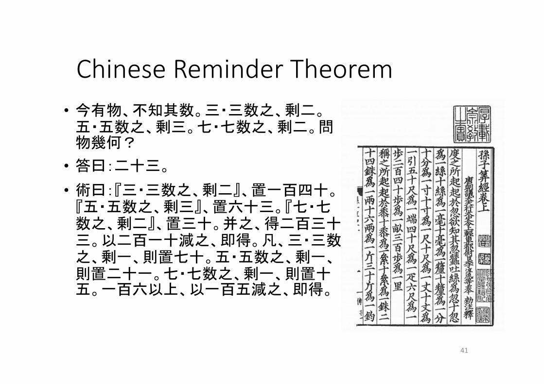
Chinese Reminder Theorem• 今有物、不知其数。三・三数之、剰二。五・五数之、剰三。七・七数之、剰二。問物幾何?
• 答曰:二十三。
• 術曰:『三・三数之、剰二』、置一百四十。『五・五数之、剰三』、置六十三。『七・七数之、剰二』、置三十。并之、得二百三十三。以二百一十減之、即得。凡、三・三数之、剰一、則置七十。五・五数之、剰一、則置二十一。七・七数之、剰一、則置十五。一百六以上、以一百五減之、即得。
41
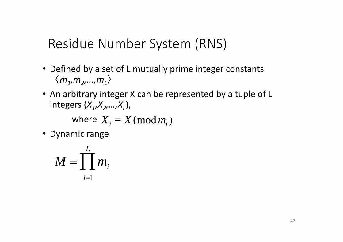
Residue Number System (RNS)
• Defined by a set of L mutually prime integer constants 〈m1,m2,...,mL〉
• An arbitrary integer X can be represented by a tuple of L integers (X1,X2,…,XL),
where• Dynamic range
42
)(mod ii mXX
M mii1
L
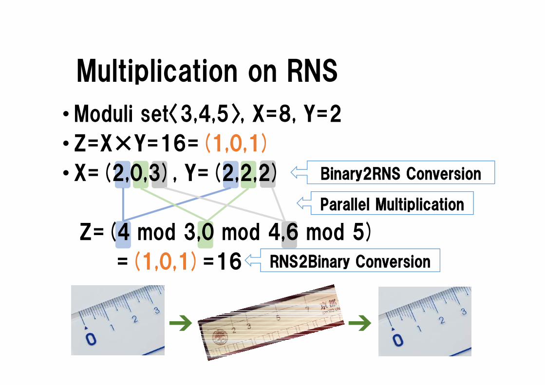
Parallel Multiplication
Multiplication on RNS
•Moduli set〈3,4,5〉, X=8, Y=2
• Z=X×Y=16=(1,0,1)
• X=(2,0,3), Y=(2,2,2)
Z=(4 mod 3,0 mod 4,6 mod 5)
=(1,0,1)=16
43
Binary2RNS Conversion
RNS2Binary Conversion
➔ ➔
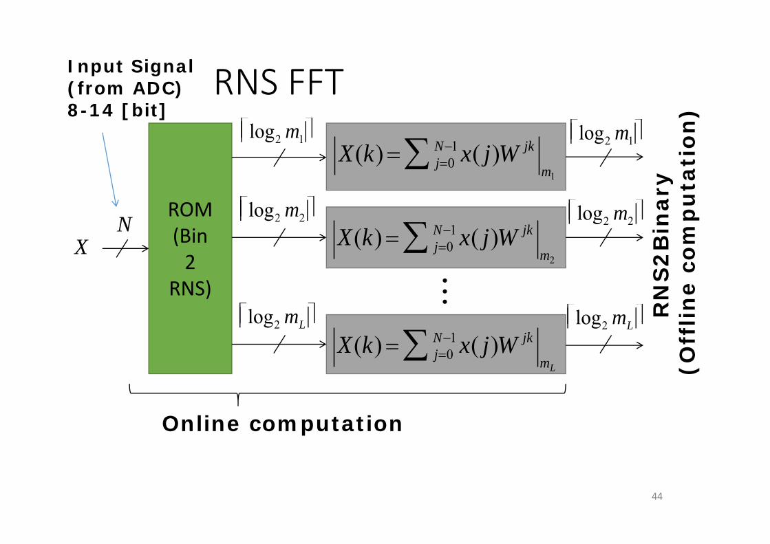
RNS FFT
44
ROM(Bin2
RNS)
X(k) j0N1 x( j)W jk
m1
X(k) j0N1 x( j)W jk
m2
X(k) j0N1 x( j)W jk
mL
RN
S2
Bin
ary
(Off
line
com
pu
tati
on)
Online computation
log2 m1
log2 m2
log2 mL log2 mL
log2 m2
log2 m1
X
Input Signal(from ADC)8-14 [bit]
N
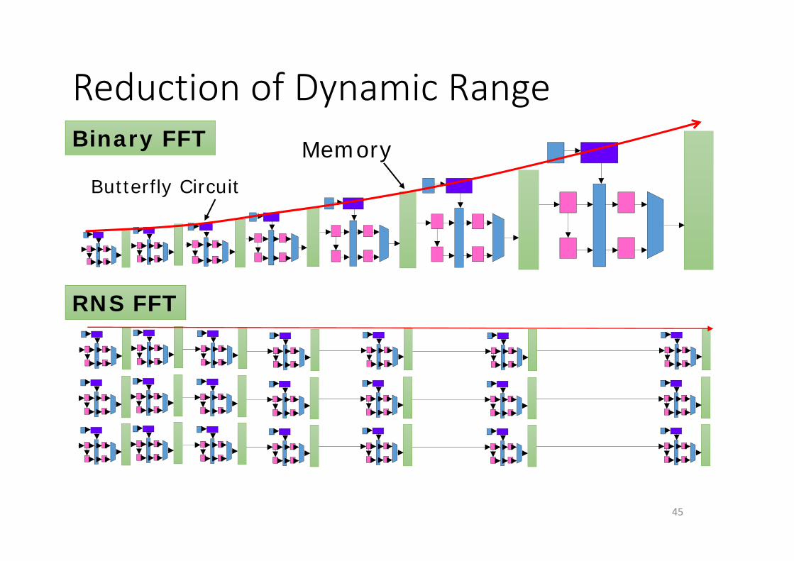
Reduction of Dynamic Range
45
Binary FFT Memory
RNS FFT
Butterfly Circuit
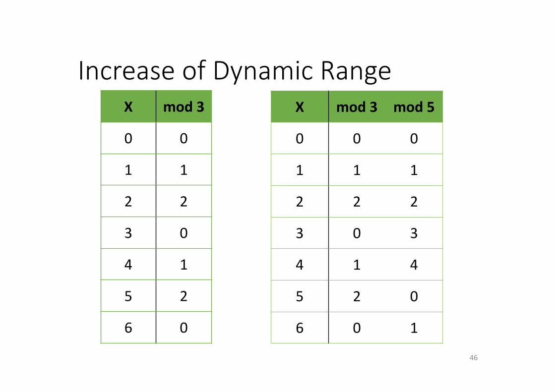
Increase of Dynamic Range
46
X mod 3
0 0
1 1
2 2
3 0
4 1
5 2
6 0
X mod 3 mod 5
0 0 0
1 1 1
2 2 2
3 0 3
4 1 4
5 2 0
6 0 1
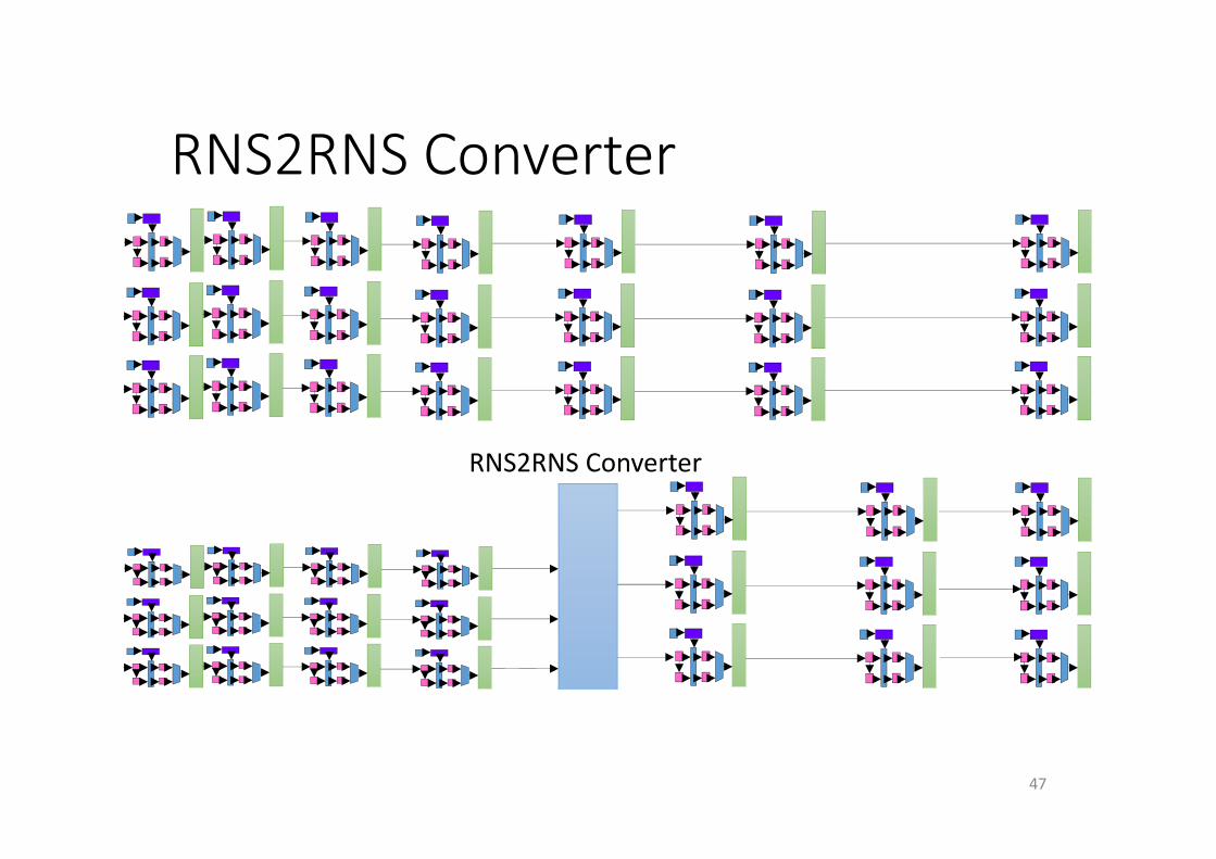
RNS2RNS Converter
47
RNS2RNS Converter
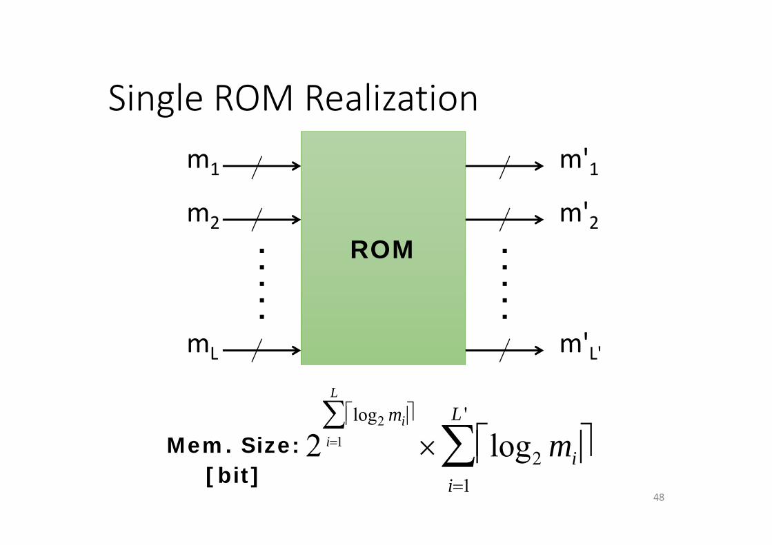
Single ROM Realization
48
ROM
m1
m2
mL
m'1
m'2
m'L'
2log2 mi
i1
L
log2 mi
i1
L '
Mem. Size:[bit]
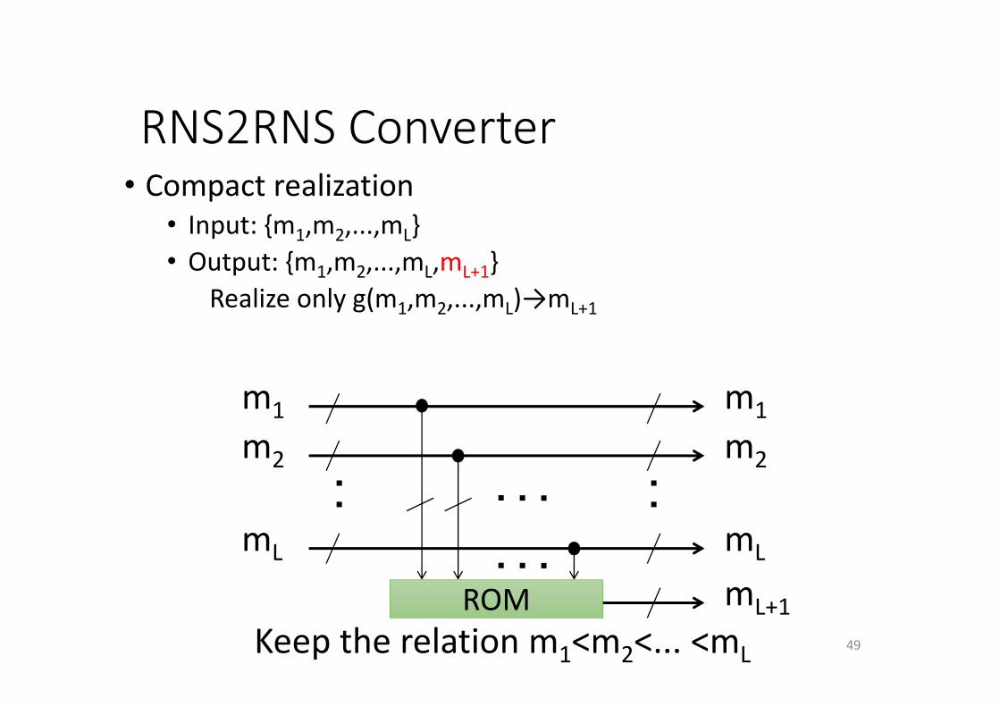
RNS2RNS Converter• Compact realization
• Input: {m1,m2,...,mL}• Output: {m1,m2,...,mL,mL+1}
Realize only g(m1,m2,...,mL)→mL+1
49
ROM
m1
m2
mL
m1
m2
mL
mL+1Keep the relation m1<m2<... <mL
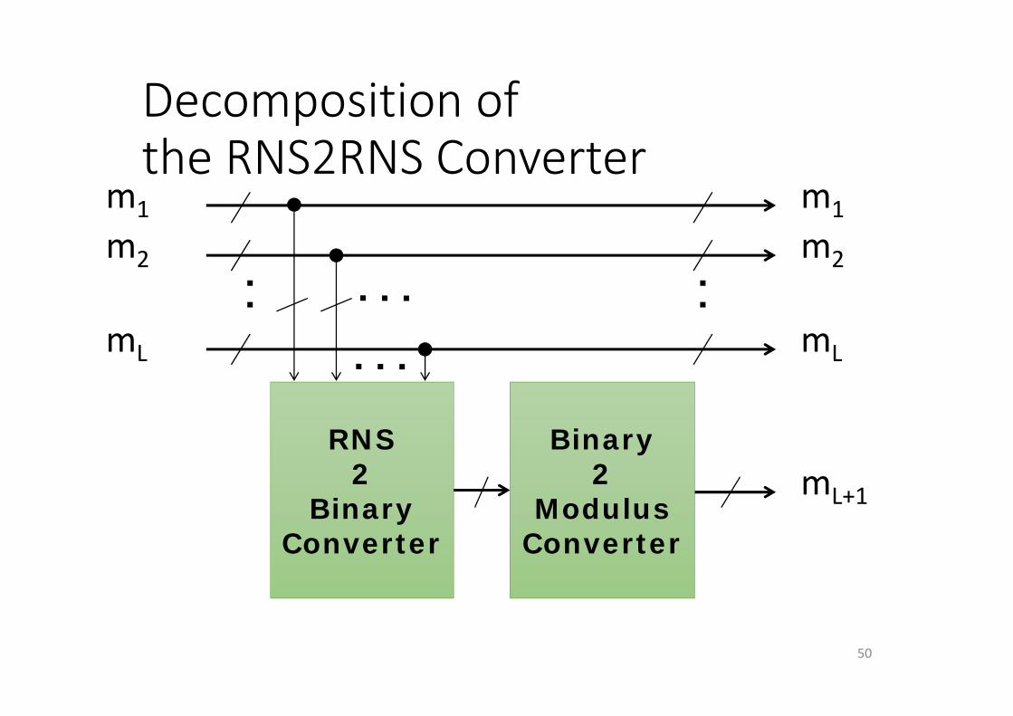
Decomposition of the RNS2RNS Converter
50
m1
m2
mL
m1
m2
mL
mL+1
RNS2
BinaryConverter
Binary2
ModulusConverter
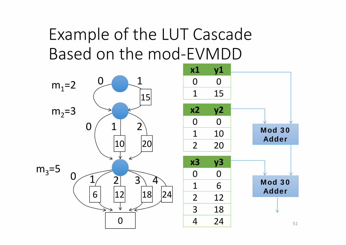
Example of the LUT Cascade Based on the mod‐EVMDD
510
1
0
m1=2
m2=3
m3=5
15
0
10 20
6 12 18 24
1 2
0 1 2 3 4
x1 y10 01 15
x2 y20 01 102 20
x3 y30 01 62 123 184 24
Mod 30Adder
Mod 30Adder
52
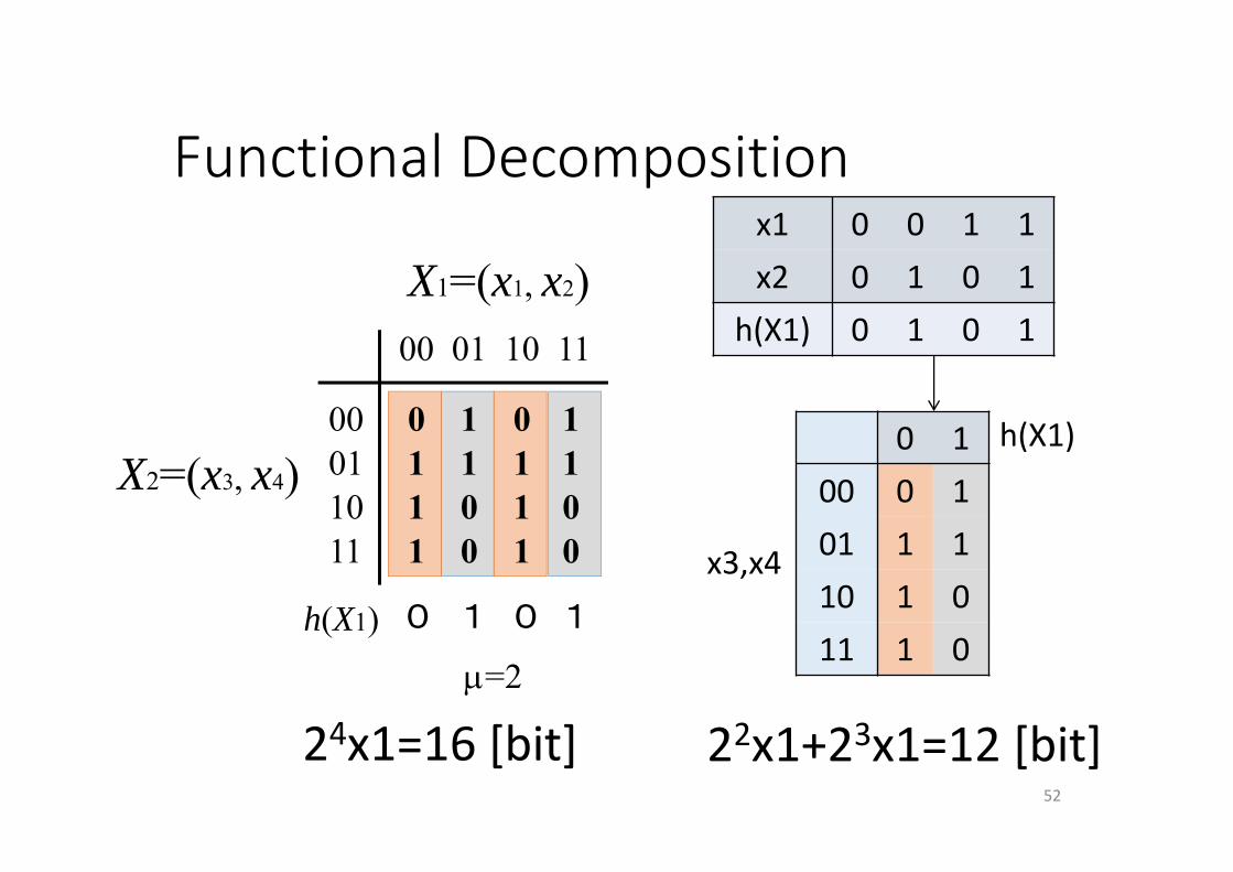
00 01 10 11
00011011
0111
1100
0111
1100
X1=(x1, x2)
X2=(x3, x4)
=2h(X1) 0 01 1
x1 0 0 1 1x2 0 1 0 1
h(X1) 0 1 0 1
0 100 0 101 1 110 1 011 1 0
x3,x4
h(X1)
Functional Decomposition
24x1=16 [bit] 22x1+23x1=12 [bit]
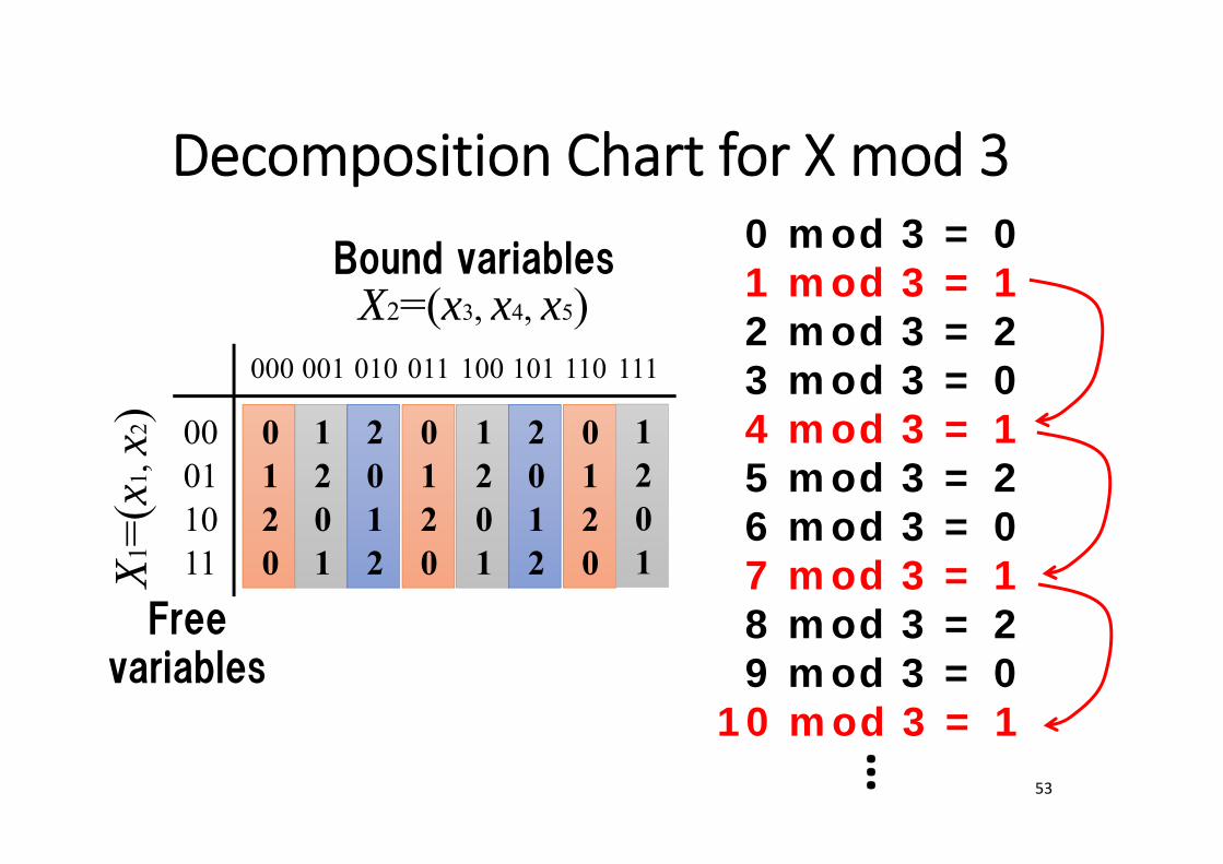
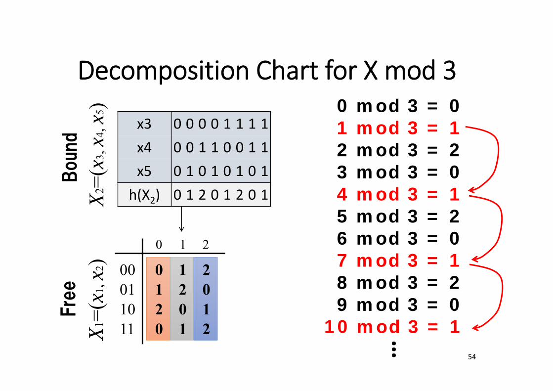
Decomposition Chart for X mod 3
53
000 001 010 011
00011011
0120
1201
2012
0120
X2=(x3, x4, x5)
X1=(
x1, x
2)
100 101 110 111
1201
2012
0120
1201
0 mod 3 = 01 mod 3 = 12 mod 3 = 23 mod 3 = 04 mod 3 = 15 mod 3 = 26 mod 3 = 07 mod 3 = 18 mod 3 = 29 mod 3 = 0
10 mod 3 = 1
…
Freevariables
Bound variables
Decomposition Chart for X mod 3
54
0 1 2
00011011
0120
1201
2012
X2=(
x3, x
4, x5
)X 1
=(x1
, x2)
0 mod 3 = 01 mod 3 = 12 mod 3 = 23 mod 3 = 04 mod 3 = 15 mod 3 = 26 mod 3 = 07 mod 3 = 18 mod 3 = 29 mod 3 = 0
10 mod 3 = 1
…
Fre
eBound
x3 0 0 0 0 1 1 1 1x4 0 0 1 1 0 0 1 1x5 0 1 0 1 0 1 0 1
h(X2) 0 1 2 0 1 2 0 1

RNS2RNS Converter using LUT Cascades
55
Modulo MAdder
ROM
ROM
ROM
m1
m2
mL
ROM
ROM
ROM mL+1
12log Lm
RNS2Binary ConverterUsing LUT cascades
based on mod-EVMDD
Binary2ModulusConverter
using LUT cascadesbased on MTMDD
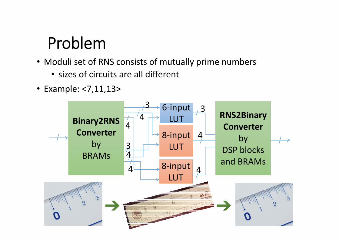
Problem• Moduli set of RNS consists of mutually prime numbers
• sizes of circuits are all different• Example: <7,11,13>
56
6‐inputLUT
8‐inputLUT
8‐inputLUT
34
4
443
3
4
4
Binary2RNSConverter
byBRAMs
RNS2BinaryConverter
byDSP blocksand BRAMs
➔ ➔

Nested RNS• (Z1,Z2,…,Zi,…, ZL) (Z1,Z2,…,(Zi1,Zi2,…,Zij),…, ZL)• Ex: <7,11,13>×<7,11,13>
<7,<5,6,7>11,<5,6,7>13>×<7,<5,6,7>11,<5,6,7>13>
57
1. Reuse the same moduli set
2. Decompose a large modulo into smaller ones
Original modulus
➔
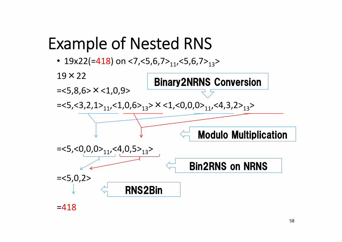
Example of Nested RNS• 19x22(=418) on <7,<5,6,7>11,<5,6,7>13>19×22=<5,8,6>×<1,0,9>=<5,<3,2,1>11,<1,0,6>13>×<1,<0,0,0>11,<4,3,2>13>
=<5,<0,0,0>11,<4,0,5>13>
=<5,0,2>
=41858
Modulo Multiplication
Bin2RNS on NRNS
RNS2Bin
Binary2NRNS Conversion
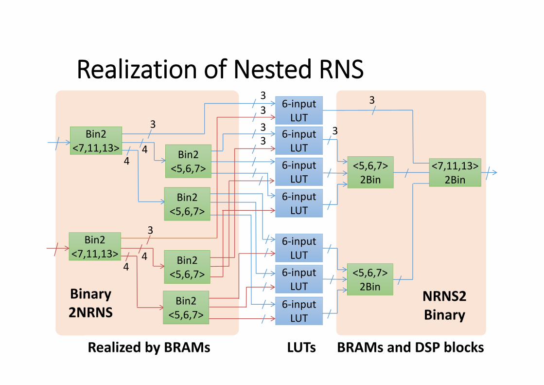
Realization of Nested RNS
59
<5,6,7>2Bin
Bin2<7,11,13>
3
<7,11,13>2Bin
<5,6,7>2Bin
Bin2<5,6,7>
Bin2<5,6,7>
6‐inputLUT
6‐inputLUT
6‐inputLUT
6‐inputLUT
6‐inputLUT
6‐inputLUT
6‐inputLUT
Bin2<7,11,13> Bin2
<5,6,7>
Bin2<5,6,7>
44
3
44
3333
3
3
Binary2NRNS
NRNS2Binary
Realized by BRAMs LUTs BRAMs and DSP blocks
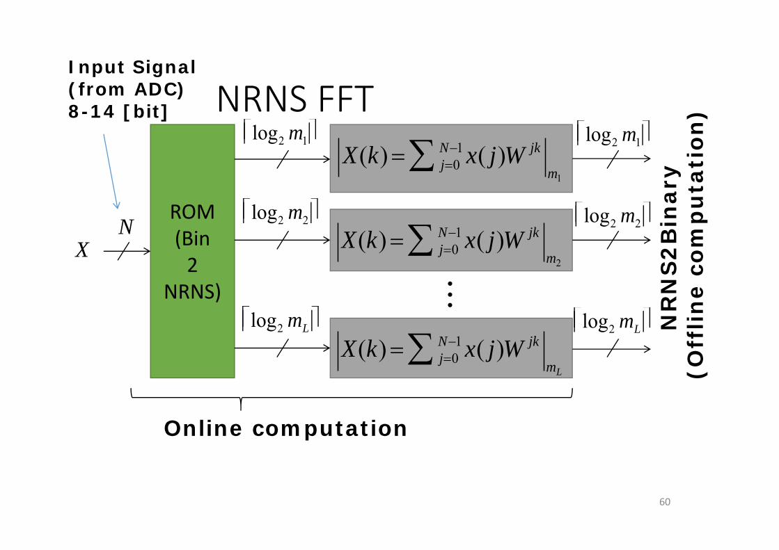
NRNS FFT
60
ROM(Bin2
NRNS)
X(k) j0N1 x( j)W jk
m1
X(k) j0N1 x( j)W jk
m2
X(k) j0N1 x( j)W jk
mL
NR
NS
2B
inar
y(O
fflin
e co
mp
uta
tion
)
Online computation
log2 m1
log2 m2
log2 mL log2 mL
log2 m2
log2 m1
X
Input Signal(from ADC)8-14 [bit]
N
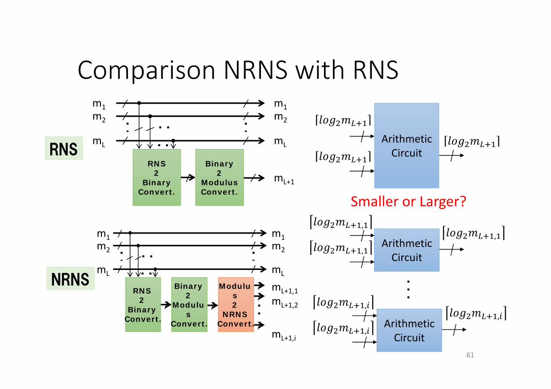
Comparison NRNS with RNS
61
m1m2
mL
m1m2
mL
mL+1,1mL+1,2
mL+1,i
RNS2
BinaryConvert.
Binary2
Modulus
Convert.
Modulus2
NRNSConvert.
m1m2
mL
m1m2
mL
mL+1
RNS2
BinaryConvert.
Binary2
ModulusConvert.
RNS
NRNS
ArithmeticCircuit
ArithmeticCircuit
,
,
,
ArithmeticCircuit
,
,
,
Smaller or Larger?
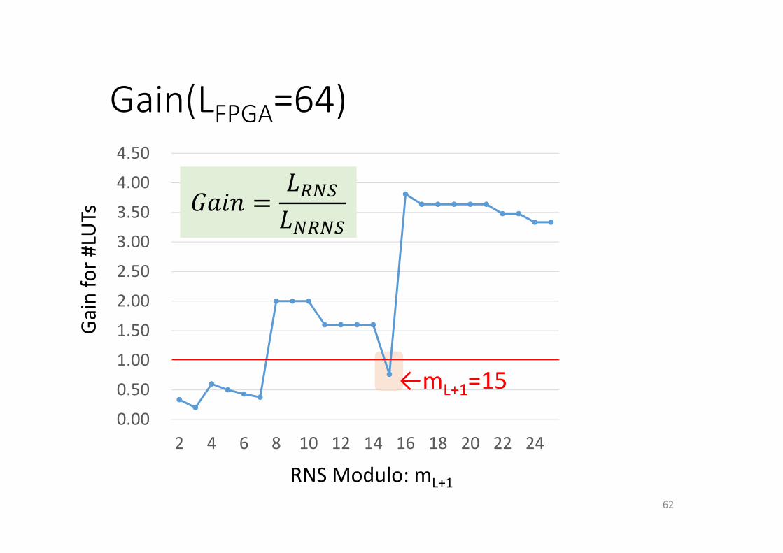
Gain(LFPGA=64)
62
0.00
0.50
1.00
1.50
2.00
2.50
3.00
3.50
4.00
4.50
2 4 6 8 10 12 14 16 18 20 22 24
Gain for #
LUTs
RNS Modulo: mL+1
←mL+1=15
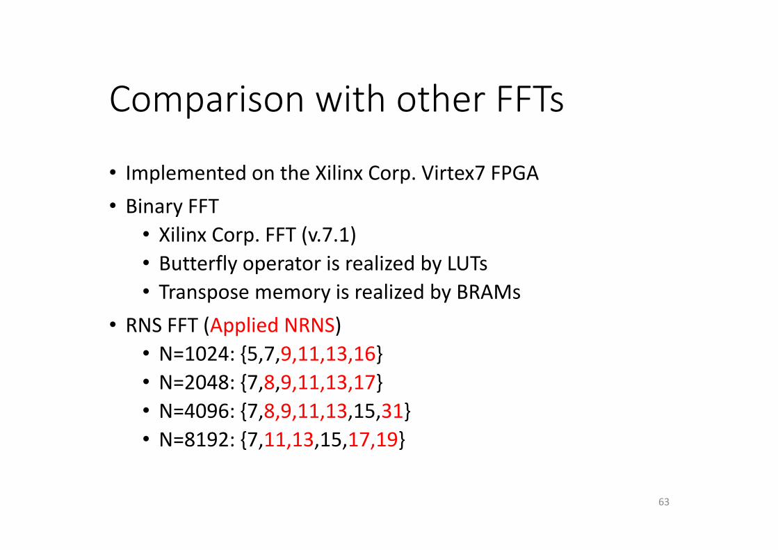
Comparison with other FFTs
• Implemented on the Xilinx Corp. Virtex7 FPGA• Binary FFT
• Xilinx Corp. FFT (v.7.1)• Butterfly operator is realized by LUTs• Transpose memory is realized by BRAMs
• RNS FFT (Applied NRNS)• N=1024: {5,7,9,11,13,16}• N=2048: {7,8,9,11,13,17}• N=4096: {7,8,9,11,13,15,31}• N=8192: {7,11,13,15,17,19}
63
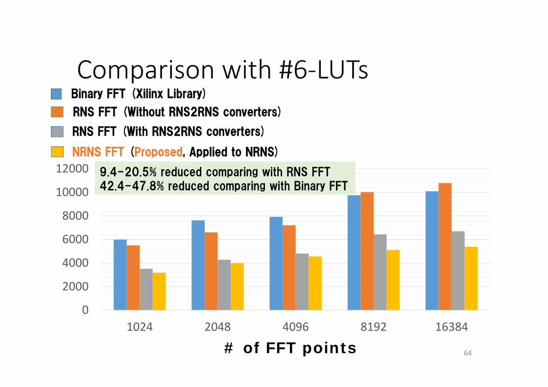
Comparison with #6‐LUTs
64
0
2000
4000
6000
8000
10000
12000
1024 2048 4096 8192 16384
# of FFT points
Binary FFT (Xilinx Library)
RNS FFT (Without RNS2RNS converters)
RNS FFT (With RNS2RNS converters)
NRNS FFT (Proposed, Applied to NRNS)
9.4-20.5% reduced comparing with RNS FFT42.4-47.8% reduced comparing with Binary FFT
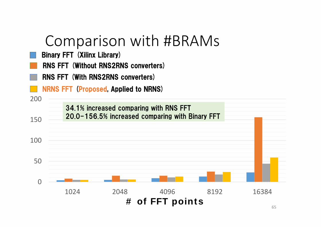
Comparison with #BRAMs
65
0
50
100
150
200
1024 2048 4096 8192 16384# of FFT points
34.1% increased comparing with RNS FFT20.0-156.5% increased comparing with Binary FFT
Binary FFT (Xilinx Library)
RNS FFT (Without RNS2RNS converters)
RNS FFT (With RNS2RNS converters)
NRNS FFT (Proposed, Applied to NRNS)
Outline
• Introduction• Digital spectrometer for a radio telescope
• ROACH system at Oxford University• Realization Highly Throughput/Area on the FPGA
• Nested residue number system (Nested RNS)• Implementation
• Future plans• Conclusion
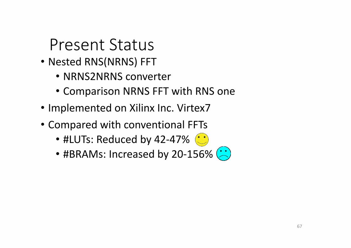
Present Status• Nested RNS(NRNS) FFT
• NRNS2NRNS converter• Comparison NRNS FFT with RNS one
• Implemented on Xilinx Inc. Virtex7• Compared with conventional FFTs
• #LUTs: Reduced by 42‐47%• #BRAMs: Increased by 20‐156%
67
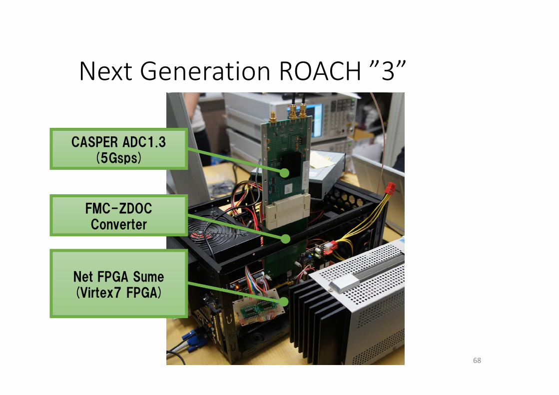
Next Generation ROACH ”3”
68
Net FPGA Sume(Virtex7 FPGA)
FMC-ZDOCConverter
CASPER ADC1.3(5Gsps)
69
Questions?