NACE TM0173
19
NACE Standard TM0173-2005 Item No. 21205 Standard Test Method Methods for Determining Quality of Subsurface Injection Water Using Membrane Filters This NACE International standard represents a consensus of those individual members who have reviewed this document, its scope, and provisions. Its acceptance does not in any respect preclude anyone, whether he has adopted the standard or not, from manufacturing, marketing, purchasing, or using products, processes, or procedures not in conformance with this standard. Nothing contained in this NACE International standard is to be construed as granting any right, by implication or otherwise, to manufacture, sell, or use in connection with any method, apparatus, or product covered by Letters Patent, or as indemnifying or protecting anyone against liability for infringement of Letters Patent. This standard represents minimum requirements and should in no way be interpreted as a restriction on the use of better procedures or materials. Neither is this standard intended to apply in all cases relating to the subject. Unpredictable circumstances may negate the usefulness of this standard in specific instances. NACE International assumes no responsibility for the interpretation or use of this standard by other parties and accepts responsibility for only those official NACE International interpretations issued by NACE International in accordance with its governing procedures and policies which preclude the issuance of interpretations by individual volunteers. Users of this NACE International standard are responsible for reviewing appropriate health, safety, environmental, and regulatory documents and for determining their applicability in relation to this standard prior to its use. This NACE International standard may not necessarily address all potential health and safety problems or environmental hazards associated with the use of materials, equipment, and/or operations detailed or referred to within this standard. Users of this NACE International standard are also responsible for establishing appropriate health, safety, and environmental protection practices, in consultation with appropriate regulatory authorities if necessary, to achieve compliance with any existing applicable regulatory requirements prior to the use of this standard. CAUTIONARY NOTICE: NACE International standards are subject to periodic review, and may be revised or withdrawn at any time without prior notice. NACE International requires that action be taken to reaffirm, revise, or withdraw this standard no later than five years from the date of initial publication. The user is cautioned to obtain the latest edition. Purchasers of NACE International standards may receive current information on all standards and other NACE International publications by contacting the NACE Firstservice Department, 1440 South Creek Drive, Houston, TX, 77084-4906 (telephone + I [281] 228-6200). Reaffirmed 2005-04-07 Revised 1999-06-25 Revised August 1992 Revised February 1984 Reaffirmed February 1983 Revised June 1976 Approved February 1973 NACE International 1440 South Creek Drive Houston, Texas 77084-4906 + I (281) 228-6200 ISBN 1-57590-085-8 O 2005, NACE International Copyright NACE International Provided by IHS under license with NACE Licensee=Daelim Industrial Co Ltd/5935606001 Not for Resale, 09/17/2009 19:17:49 MDT No reproduction or networking permitted without license from IHS --``,,,``,`,`,`,,,,``,``,``,,`,,-`-`,,`,,`,`,,`---
-
Upload
cjstpdngml -
Category
Documents
-
view
2.117 -
download
268
Transcript of NACE TM0173

5/14/2018 NACE TM0173 - slidepdf.com
http://slidepdf.com/reader/full/nace-tm0173 1/19
NACE Standard TM0173-2005Item No. 21205
Standard
Test Method
Methods for Determining Quality of Subsurface
Injection Water Using Membrane Filters
This NACE International standard represents a consensus of those individual members who have
reviewed this document, its scope, and provisions. Its acceptance does not in any respect
preclude anyone, whether he has adopted the standard or not, from manufacturing, marketing,
purchasing, or using products, processes, or procedures not in conformance with this standard.
Nothing contained in this NACE International standard is to be construed as granting any right, by
implication or otherwise, to manufacture, sell, or use in connection with any method, apparatus, or
product covered by Letters Patent, or as indemnifying or protecting anyone against liability forinfringement of Letters Patent. This standard represents minimum requirements and should in no
way be interpreted as a restriction on the use of better procedures or materials. Neither is this
standard intended to apply in all cases relating to the subject. Unpredictable circumstances may
negate the usefulness of this standard in specific instances. NACE International assumes no
responsibility for the interpretation or use of this standard by other parties and accepts
responsibility for only those official NACE International interpretations issued by NACE
International in accordance with its governing procedures and policies which preclude the
issuance of interpretations by individual volunteers.
Users of this NACE International standard are responsible for reviewing appropriate health, safety,
environmental, and regulatory documents and for determining their applicability in relation to this
standard prior to its use. This NACE International standard may not necessarily address all
potential health and safety problems or environmental hazards associated with the use of
materials, equipment, and/or operations detailed or referred to within this standard. Users of this
NACE International standard are also responsible for establishing appropriate health, safety, andenvironmental protection practices, in consultation with appropriate regulatory authorities if
necessary, to achieve compliance with any existing applicable regulatory requirements prior to the
use of this standard.
CAUTIONARY NOTICE: NACE International standards are subject to periodic review, and may be
revised or withdrawn at any time without prior notice. NACE International requires that action be
taken to reaffirm, revise, or withdraw this standard no later than five years from the date of initial
publication. The user is cautioned to obtain the latest edition. Purchasers of NACE International
standards may receive current information on all standards and other NACE International
publications by contacting the NACE Firstservice Department, 1440 South Creek Drive, Houston,
TX, 77084-4906 (telephone + I [281] 228-6200).
Reaffirmed 2005-04-07
Revised 1999-06-25
Revised August 1992Revised February 1984
Reaffirmed February 1983
Revised June 1976
Approved February 1973
NACE International
1440 South Creek Drive
Houston, Texas 77084-4906
+ I (281) 228-6200
ISBN 1-57590-085-8
O 2005, NACE International
Copyright NACE InternationalProvided by IHS under license with NACE Licensee=Daelim Industrial Co Ltd/5935606001
Not for Resale, 09/17/2009 19:17:49 MDT
No reproduction or networking permitted without license from IHS
--``,,,``,`,`,`,,,,``,``,``,,`,,-`-`,,`,,`,`,,`---
5/14/2018 NACE TM0173 - slidepdf.com
http://slidepdf.com/reader/full/nace-tm0173 2/19
TM0173-2005
Foreword
Corrosion engineers in the oil- and gas-producing industry are often charged with the responsibility
of evaluating and controlling the quality of injection waters. Unfortunately, much of the dataavailable are inadequate, misleading, or difficult to interpret. This standard was prepared to
provide standard test methods for use by these engineers in evaluating water quality for injection
waters.
This standard was originally prepared in 1973 by NACE Task Group T-IC-12, revised in 1976,
reaffirmed in 1983, and revised in 1984 and 1992 by T-IC-20, components of Unit Committee T-
I C on Detection of Corrosion in Oilfield Equipment. T- IC was combined with T- ID on Corrosion
Monitoring and Control of Corrosion Environments in Petroleum Production Operations. This
standard was revised by T-ID-47 in 1999 and reaffirmed in 2005 by Specific Technology Group
(STG) 31 on Oil and Gas Production-Corrosion and Scale Inhibition. This standard is issued by
NACE International under the auspices of STG 31.
In NACE standards, the terms shall, must, should, and may are used in accordance with the
definitions of these terms in the NACE Publications Style Manual, 4th ed., Paragraph 7.4.1.9. Shall
and must are used to state mandatory requirements. The term should is used to state something
good and is recommended but is not mandatory. The term may is used to state something
considered optional.
NACE International I
Copyright NACE InternationalProvided by IHS under license with NACE Licensee=Daelim Industrial Co Ltd/5935606001
Not for Resale, 09/17/2009 19:17:49 MDT
No reproduction or networking permitted without license from IHS

5/14/2018 NACE TM0173 - slidepdf.com
http://slidepdf.com/reader/full/nace-tm0173 3/19
TM0173-2005
NACE InternationalStanda rd
Test Method
Methods for Determining Quality of Subsurface InjectionWater Using Membrane Filters
Contents
1. General ......................................................................................................................... 1
2. Definitions ..................................................................................................................... 1
3. Description of Test Methods ......................................................................................... 2
4. Test Apparatus .............................................................................................................. 3
5. Preparation for Testing ................................................................................................. 6
6 . Test Conditions ............................................................................................................. 7
7. Test Procedures ........................................................................................................... 7
11
12
...................................................................................................................... 12Appendix A ........................................................................................................................ 12
Appendix B ........................................................................................................................ 13
Appendix C ....................................................................................................................... 15
Figure 1: Example of a membrane filter holder for 47-mm (1.8-in.) membrane filter. ........ 3
Figure 2: Membrane filter test apparatus showing membrane filter holder from Figure 1
Figure 3: Two-stage test apparatus with pressure gauge and regulator for repressurizing
and testing sample from reservoir rather than water-handling system (Figure 2), used
mainly when sample point cannot be easily adapted to on-stream application ............ 6Figure 4: Example of a graphic representation of water quality. ........................................ 9Figure 5: Apparatus for various washings or extractions by vacuum filtration. ................. 10
Table 1 Example of Membrane Filter Test Data.............................................................. 11
. .
connected to water-handling system 4
..II NACE International
Copyright NACE InternationalProvided by IHS under license with NACE Licensee=Daelim Industrial Co Ltd/5935606001
Not for Resale, 09/17/2009 19:17:49 MDT
No reproduction or networking permitted without license from IHS
5/14/2018 NACE TM0173 - slidepdf.com
http://slidepdf.com/reader/full/nace-tm0173 4/19
TM0173-2005
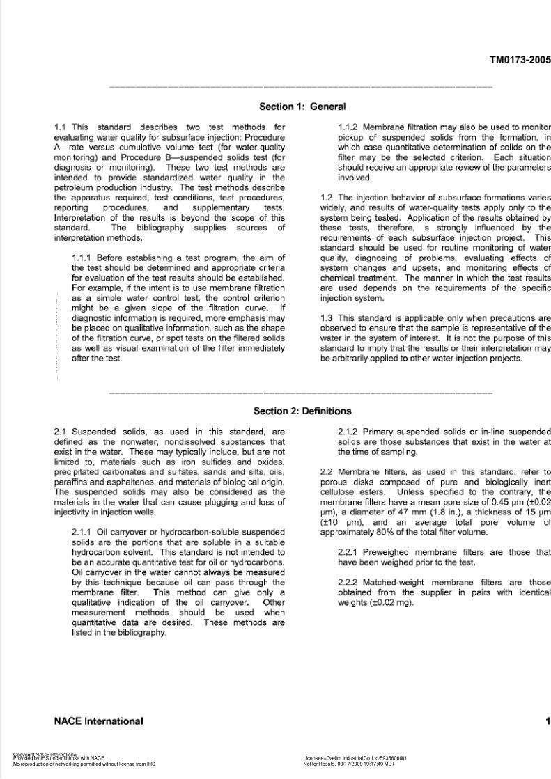
Section 1: General
1.1 This standard describes two test methods for
evaluating water quality for subsurface injection: Procedure
A-rate versus cumulative volume test (for water-qualitymonitoring) and Procedure B-suspended solids test (for
diagnosis or monitoring). These two test methods are
intended to provide standardized water quality in the
petroleum production industry. The test methods describe
the apparatus required, test conditions, test procedures,
reporting procedures, and supplementary tests.
Interpretation of the results is beyond the scope of this
standard. The bibliography supplies sources of
interpretation methods.
1.1.1 Before establishing a test program, the aim of
the test should be determined and appropriate criteria
for evaluation of the test results should be established.
For example, if the intent is to use membrane filtration
as a simple water control test, the control criterionmight be a given slope of the filtration curve. If
diagnostic information is required, more emphasis may
be placed on qualitative information, such as the shape
of the filtration curve, or spot tests on the filtered solids
as well as visual examination of the filter immediately
after the test.
1.1.2 Membrane filtration may also be used to monitor
pickup of suspended solids from the formation, in
which case quantitative determination of solids on thefilter may be the selected criterion. Each situation
should receive an appropriate review of the parameters
involved
1.2 The injection behavior of subsurface formations varies
widely, and results of water-quality tests apply only to the
system being tested. Application of the results obtained by
these tests, therefore, is strongly influenced by the
requirements of each subsurface injection project. This
standard should be used for routine monitoring of water
quality, diagnosing of problems, evaluating effects of
system changes and upsets, and monitoring effects of
chemical treatment. The manner in which the test results
are used depends on the requirements of the specific
injection system.
1.3 This standard is applicable only when precautions are
observed to ensure that the sample is representative of the
water in the system of interest. It is not the purpose of this
standard to imply that the results or their interpretation may
be arbitrarily applied to other water injection projects.
Section 2: Definitions
2.1 Suspended solids, as used in this standard, are
defined as the nonwater, nondissolved substances that
exist in the water. These may typically include, but are notlimited to, materials such as iron sulfides and oxides,
precipitated carbonates and sulfates, sands and silts, oils,
paraffins and asphaltenes, and materials of biological origin.
The suspended solids may also be considered as the
materials in the water that can cause plugging and loss of
injectivity in injection wells.
2.1 I Oil carryover or hydrocarbon-soluble suspended
solids are the portions that are soluble in a suitable
hydrocarbon solvent. This standard is not intended to
be an accurate quantitative test for oil or hydrocarbons.
Oil carryover in the water cannot always be measured
by this technique because oil can pass through the
membrane filter. This method can give only a
qualitative indication of the oil carryover. Othermeasurement methods should be used when
quantitative data are desired. These methods are
listed in the bibliography.
2.1.2 Primary suspended solids or in-line suspended
solids are those substances that exist in the water at
the time of sampling.
2.2 Membrane filters, as used in this standard, refer to
porous disks composed of pure and biologically inert
cellulose esters. Unless specified to the contrary, the
membrane filters have a mean pore size of 0.45 pm (10.02
pm), a diameter of 47 mm (1.8 in.), a thickness of 15 pm
(I10 pm), and an average total pore volume of
approximately 80% of the total filter volume.
2.2.1 Preweighed membrane filters are those that
have been weighed prior to the test.
2.2.2 Matched-weight membrane filters are those
obtained from the supplier in pairs with identical
weights (I0 .02 mg).
NACE International 1
Copyright NACE InternationalProvided by IHS under license with NACE Licensee=Daelim Industrial Co Ltd/5935606001
Not for Resale, 09/17/2009 19:17:49 MDT
No reproduction or networking permitted without license from IHS
-- ̀ ̀
, , , ̀ ̀
, ̀
, ̀
, ̀
, , , , ̀ ̀
, ̀ ̀
, ̀ ̀
, , ̀
, ,- ̀
- ̀
, , ̀
, , ̀
, ̀
, , ̀
---
5/14/2018 NACE TM0173 - slidepdf.com
http://slidepdf.com/reader/full/nace-tm0173 5/19
TM0173-2005
. . . . . . . . . . . . . . . . . . . . . . . . . . . . . . . . . . . . . . . . . . . . . . . . . . . . . . . . . . . . . . . . . . . . . . . .
Section 3: Description of Test Methods
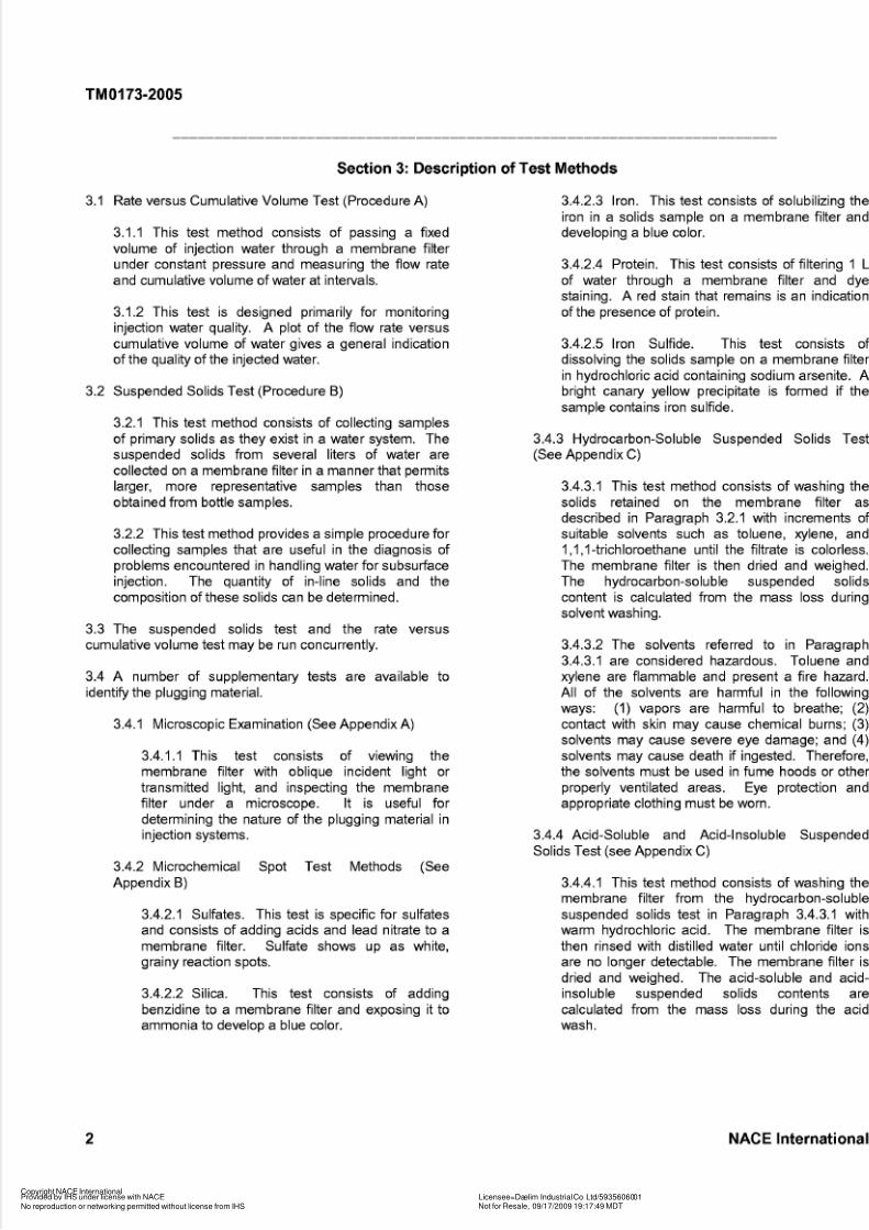
3.1 Rate versus Cumulative Volume Test (Procedure A)
3.1.1 This test method consists of passing a fixedvolume of injection water through a membrane filter
under constant pressure and measuring the flow rate
and cumulative volume of water at intervals.
3.1.2 This test is designed primarily for monitoring
injection water quality. A plot of the flow rate versus
cumulative volume of water gives a general indication
of the quality of the injected water.
3.2 Suspended Solids Test (Procedure B)
3.2.1 This test method consists of collecting samples
of primary solids as they exist in a water system. The
suspended solids from several liters of water are
collected on a membrane filter in a manner that permitslarger, more representative samples than those
obtained from bottle samples.
3.2.2 This test method provides a simple procedure for
collecting samples that are useful in the diagnosis of
problems encountered in handling water for subsurface
injection. The quantity of in-line solids and the
composition of these solids can be determined.
3.3 The suspended solids test and the rate versus
cumulative volume test may be run concurrently.
3.4 A number of supplementary tests are available to
identify the plugging material.
3.4.1 Microscopic Examination (See Appendix A)
3.4.1 I This test consists of viewing the
membrane filter with oblique incident light or
transmitted light, and inspecting the membrane
filter under a microscope. It is useful for
determining the nature of the plugging material in
injection systems.
3.4.2 Microchemical Spot Test Methods (See
Appendix B)
3.4.2.1 Sulfates. This test is specific for sulfates
and consists of adding acids and lead nitrate to a
membrane filter. Sulfate shows up as white,grainy reaction spots.
3.4.2.2 Silica. This test consists of adding
benzidine to a membrane filter and exposing it to
ammonia to develop a blue color.
3.4.2.3 Iron. This test consists of solubilizing the
iron in a solids sample on a membrane filter and
developing a blue color.
3.4.2.4 Protein. This test consists of filtering 1 L
of water through a membrane filter and dye
staining. A red stain that remains is an indication
of the presence of protein.
3.4.2.5 Iron Sulfide. This test consists of
dissolving the solids sample on a membrane filter
in hydrochloric acid containing sodium arsenite. A
bright canary yellow precipitate is formed if the
sample contains iron sulfide.
3.4.3 Hydrocarbon-Soluble Suspended Solids Test
(See Appendix C)
3.4.3.1 This test method consists of washing the
solids retained on the membrane filter as
described in Paragraph 3.2.1 with increments of
suitable solvents such as toluene, xylene, and
1 I I-trichloroethane until the filtrate is colorless.
The membrane filter is then dried and weighed.
The hydrocarbon-soluble suspended solids
content is calculated from the mass loss during
solvent washing.
3.4.3.2 The solvents referred to in Paragraph
3.4.3.1 are considered hazardous. Toluene and
xylene are flammable and present a fire hazard.
All of the solvents are harmful in the following
ways: (1) vapors are harmful to breathe; (2)contact with skin may cause chemical burns; (3)
solvents may cause severe eye damage; and (4)
solvents may cause death if ingested. Therefore,
the solvents must be used in fume hoods or other
properly ventilated areas. Eye protection and
appropriate clothing must be worn.
3.4.4 Acid-Soluble and Acid-Insoluble Suspended
Solids Test (see Appendix C)
3.4.4.1 This test method consists of washing the
membrane filter from the hydrocarbon-soluble
suspended solids test in Paragraph 3.4.3.1 with
warm hydrochloric acid. The membrane filter is
then rinsed with distilled water until chloride ionsare no longer detectable. The membrane filter is
dried and weighed. The acid-soluble and acid-
insoluble suspended solids contents are
calculated from the mass loss during the acid
wash.
2 NACE International
Copyright NACE InternationalProvided by IHS under license with NACE Licensee=Daelim Industrial Co Ltd/5935606001
Not for Resale, 09/17/2009 19:17:49 MDT
No reproduction or networking permitted without license from IHS

5/14/2018 NACE TM0173 - slidepdf.com
http://slidepdf.com/reader/full/nace-tm0173 6/19
TM0173-2005
Section 4: Test Apparatus
4.1 The test apparatus consists of the membrane filters, be run on line as in Figure 2, a sample reservoir may bemembrane filter holders (shown in Figure I),ample used. Except as noted, the same apparatus is used for
receiver, sample connections and fittings, and pressure- ProcedureA and ProcedureB.regulation devices. As an alternative, when the test cannot
FIGURE 1: Example of a membrane filter holder fo r 47-mm (1.8411.) membrane filter. Construction is of
corrosion-resistant materials capable of withstanding upstream pressure of 14 MPa (2,000 psig). The holder
is designed for quick connection to a water-handling system to prevent detrimental aeration effects, and is
also designed for rapid assembly or dismantling.
NACE International 3
Copyright NACE International
Provided by IHS under license with NACE Licensee=Daelim Industrial Co Ltd/5935606001
Not for Resale, 09/17/2009 19:17:49 MDTNo reproduction or networking permitted without license from IHS
--``,,,``,`,`,`,,,,``,``,``,,`,,-`-`,,`,,`,`,,`---

5/14/2018 NACE TM0173 - slidepdf.com
http://slidepdf.com/reader/full/nace-tm0173 7/19
TM0173-2005
, Asample Manifold
Nipple
adlevalve \\
Toggle Valve*embrane Filter Holder
4raduated Cylinder
FIGURE 2: Membrane filter test apparatus showing membrane filter holder from Figure 1connected to water-
handling system. The 6.4-mm nominal OD (%-in. NPT) block and needle valves near the top keep system
pressure within set limits. Above the membrane filter holder is a quick-opening oggle valve to allow
immediate full-stream flow vital to timing accuracy. Length of tubing between the source and the apparatus
should be minimized o prevent forming a “dead leg.”
4.1.1 The pressure ratings of the test equipment
discussed in Paragraphs 4.3, 4.4, and 4.5 must be
strongly considered from a safety standpoint. When a
water injection system operating, for example, at 7, 14,or 28 MPa (1,000, 2,000, or 4,000 psi) is to be
sampled, the test equipment must be designed to
handle these pressures safely. This can be
accomplished by (1) selection of test equipment that
has the required pressure rating or (2) placement of a
proper pressure-relief valve located immediately
downstream from the injection system’s sample valve.
An alternative method that has been used is that
shown in Figure 2.4 in Applied Water Technology.’
4.2 Membrane Filter
4.2.1 The membrane filter defined in Paragraph 2.2
should be used for the rate versus cumulative volumetest (Procedure A). The diameter of the membrane
filter is less critical when only the suspended solids test
(Procedure B) is to be conducted, but a fixed diameter
should be used for all comparative tests. The
membrane filter should have a smooth surface to
permit easy removal of filtered solids.
4.2.2 Matched-weight membrane filters may be used
to help distinguish true suspended solids from
4 NACE International
Copyright NACE International
Provided by IHS under license with NACE Licensee=Daelim Industrial Co Ltd/5935606001
Not for Resale, 09/17/2009 19:17:49 MDTNo reproduction or networking permitted without license from IHS
5/14/2018 NACE TM0173 - slidepdf.com
http://slidepdf.com/reader/full/nace-tm0173 8/19
TM0173-2005
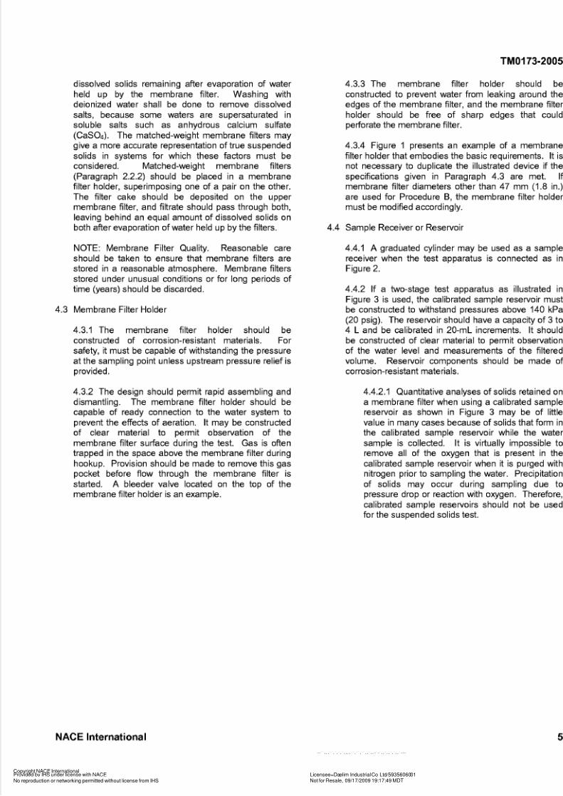
dissolved solids remaining after evaporation of water
held up by the membrane filter. Washing with
deionized water shall be done to remove dissolved
salts, because some waters are supersaturated in
soluble salts such as anhydrous calcium sulfate
(Caso,). The matched-weight membrane filters may
give a more accurate representation of true suspended
solids in systems for which these factors must beconsidered. Matched-weight membrane filters
(Paragraph 2.2.2) should be placed in a membrane
filter holder, superimposing one of a pair on the other.
The filter cake should be deposited on the upper
membrane filter, and filtrate should pass through both,
leaving behind an equal amount of dissolved solids on
both after evaporation of water held up by the filters.
NOTE: Membrane Filter Quality. Reasonable care
should be taken to ensure that membrane filters are
stored in a reasonable atmosphere. Membrane filters
stored under unusual conditions or for long periods of
time (years) should be discarded.
4.3 Membrane Filter Holder
4.3.1 The membrane filter holder should be
constructed of corrosion-resistant materials. For
safety, it must be capable of withstanding the pressure
at the sampling point unless upstream pressure relief is
provided.
4.3.2 The design should permit rapid assembling and
dismantling. The membrane filter holder should be
capable of ready connection to the water system to
prevent the effects of aeration. It may be constructed
of clear material to permit observation of the
membrane filter sutface during the test. Gas is often
trapped in the space above the membrane filter during
hookup. Provision should be made to remove this gaspocket before flow through the membrane filter is
started. A bleeder valve located on the top of the
membrane filter holder is an example.
4.3.3 The membrane filter holder should be
constructed to prevent water from leaking around the
edges of the membrane filter, and the membrane filter
holder should be free of sharp edges that could
petforate the membrane filter.
4.3.4 Figure 1 presents an example of a membrane
filter holder that embodies the basic requirements. It isnot necessary to duplicate the illustrated device if the
specifications given in Paragraph 4.3 are met. If
membrane filter diameters other than 47 mm (1.8 in.)
are used for Procedure B, the membrane filter holder
must be modified accordingly.
4.4 Sample Receiver or Reservoir
4.4.1 A graduated cylinder may be used as a sample
receiver when the test apparatus is connected as in
Figure 2.
4.4.2 If a two-stage test apparatus as illustrated in
Figure 3 is used, the calibrated sample reservoir must
be constructed to withstand pressures above 140 kPa
(20 psig). The reservoir should have a capacity of 3 to4 L and be calibrated in 20-mL increments. It should
be constructed of clear material to permit observation
of the water level and measurements of the filtered
volume. Reservoir components should be made of
corrosion-resistant materials.
4.4.2.1 Quantitative analyses of solids retained on
a membrane filter when using a calibrated sample
reservoir as shown in Figure 3 may be of little
value in many cases because of solids that form in
the calibrated sample reservoir while the water
sample is collected. It is virtually impossible to
remove all of the oxygen that is present in the
calibrated sample reservoir when it is purged withnitrogen prior to sampling the water. Precipitation
of solids may occur during sampling due to
pressure drop or reaction with oxygen. Therefore,
calibrated sample reservoirs should not be used
for the suspended solids test.
NACE International 5
Copyright NACE InternationalProvided by IHS under license with NACE Licensee=Daelim Industrial Co Ltd/5935606001
Not for Resale, 09/17/2009 19:17:49 MDT
No reproduction or networking permitted without license from IHS
--``,,,``,`,`,`,,,,``,``,``,,`,,-`-`,,`,,`,`,,`---

5/14/2018 NACE TM0173 - slidepdf.com
http://slidepdf.com/reader/full/nace-tm0173 9/19
TM0173-2005
FIGURE 3: Tw o-stage test apparatus with pressure gauge and reg ulator for repressurizing and testingsam ple from reservoir rather than water-han dling system (FIG URE 2), used m ainly when sample point
cannot be easily adapted to on-stream application.
4.5 Sample Connections, Fittings, and Pressure
Regulation
4.5.1 Corrosion-resistant fittings, valves, and tubing
should be used to connect the test apparatus. The
tests should be run with the membrane filter holder
connected directly to the system, using suitablepressure regulators and valves to set the test pressure
(Figure 2). If the entire test apparatus can withstand
system pressure, no pressure relief is required. If,
however, the system pressure is greater than the
recommended operating pressure of any item of the
test apparatus, pressure relief shall be provided with a
pop valve, rupture disk, or other device. The valves
and regulator system shall be capable of providing a
constant pressure of 140 kPa (20 psig) or higher.
4.5.2 If a calibrated sample reservoir (Figure 3) is
used, a suitable two-stage pressure regulator shall be
used for repressurization with nitrogen.
Section 5: Preparation for Te sting
5.1 Weighing (Taring) of Membrane Filters for the 5.1.2 The tare weight of the membrane filter should be
Suspended Solids Test (Procedure B) determined to the nearest 0.1 mg (constant weight).
5.1.1 The membrane filter should be washed with 250 5.1.3 The tare weight should be recorded on the
mL of warm (31 to 34°C [88 to 93"F]), clean distilled container (petri dish, plastic case, etc.) for each
water to remove manufacturing solvents and individual membrane filter.
sutfactants.
high-quality water. The membrane filter should be 5.1.4 When high-quality water is tested, the
dried at 60°C (140°F) for two hours, cooled in a membrane filter should be prewashed with deionized
desiccator to room temperature to prevent weight gain, water prior to weighing to remove trace amounts of
and weighed prior to its use in Procedure B. When soluble material in the membrane filter.
matched-weight membrane filters are used, the
washing and drying are not necessary.
This is particularly critical when testing
6 NACE International
Copyright NACE InternationalProvided by IHS under license with NACE Licensee=Daelim Industrial Co Ltd/5935606001
Not for Resale, 09/17/2009 19:17:49 MDT
No reproduction or networking permitted without license from IHS

5/14/2018 NACE TM0173 - slidepdf.com
http://slidepdf.com/reader/full/nace-tm0173 10/19
TM0173-2005
Section 6: Test C onditions
6.1 Cleanliness
6.1.1 Prior to each test run, all parts of the testapparatus must be clean.
6.1.2 The test points must be thoroughly flushed to
ensure a representative sample.
6.2 Test Temperature
6.2.1 If the membrane filter holder is attached directly
to the system, the test temperature at the sample point
shall be measured and recorded.
6.2.2 For a repressurized test, the temperature of the
water in the calibrated sample reservoir shall be
measured and recorded.
6.3 Test Pressure
6.3.1 The test pressure for the rate versus cumulative
volume test shall be 140 kPa (20 psig) ?IO% at the
membrane filter.
6.3.2 Test pressure should be obtained by suitable
mechanical devices for on-stream sampling and by a
pressure regulator between the nitrogen source and
the calibrated sample reservoir for repressurized tests.
6.3.3 The test pressure for the suspended solids test
(Procedure B) is not very important. However, if
pressures are too low, it is difficult to flow water through
the membrane filter and some pressure assistance isrequired.
6.4 Test Sample Volume
6.4.1 For routine rate versus cumulative volume tests,
the test sample volume shall be 2.5 L. When water
quality permits rapid filtration, test samples up to 10 L
or more may be required for meaningful interpretation.
Test sample volumes of 3 or 4 L are considered
adequate to determine representative conditions in
most systems using the suspended solids test.
6.4.2 Some waters are of such poor quality that almost
complete plugging occurs before the recommended
test sample volume can be filtered. There is no
worthwhile information to be obtained from continuing
to measure effluent from the near-plugged membrane
filter. In such instances the rate versus cumulative
volume test should be terminated short of “test sample
volume.”
6.4.3 The suspended solids test should be conducted
on several membrane filters to provide an aggregate of
3 to 4 L of filtered solution. The results of the latter
tests should be averaged. When membrane filters
plug after 25 to 100 mL, it may be impractical to obtainan aggregate of 3 to 4 L of filtered solution. However,
the test should be conducted on several membrane
filters to provide a large aggregate of filtered solution.
6.5 Test Sample Points
6.5.1 Special care must be taken to ensure that a
representative sample of the water is obtained. Test
samples must be taken at points that do not contain
matter from stagnant areas, large amounts of
macrosolids such as debris and matter not
representative of injection water, and at points that are
disproportionately conducive to collecting oil or solids.
6.5.2 Although adequate and appropriate testsampling points are seldom found in existing systems,
planning for new systems should incorporate test sites.
6.5.3 In existing systems, test samples shall not be
taken at high points that tend to collect entrained oil
and drop suspended solids or at low spots that tend to
lose oil and gain solids when compared with the main
st ream.
Section 7: Test Procedures
7.1 Test Preparation. The following procedures shall be
used in preparing for the test.
7.1.1 Carefully insert the test membrane filter in the
membrane filter holder with tweezers to avoid
damaging the membrane filter and to avoid bypassing
water at an edge.
7.1.2 Moisten the test membrane filter with warm,
clean distilled water.
7.2
7.1.3 Purge the test sample point and connecting
tubing thoroughly to remove any sludge or deposits
that may have accumulated in the valve or other
fittings.
Repressurization
7.2.1 If it is not feasible to conduct an on-stream test,
collect a water sample in the calibrated sample
reservoir, after purging free of air, under an
atmosphere of nitrogen. In some cases the pressure
NACE International 7
Copyright NACE InternationalProvided by IHS under license with NACE Licensee=Daelim Industrial Co Ltd/5935606001
Not for Resale, 09/17/2009 19:17:49 MDT
No reproduction or networking permitted without license from IHS
--``,,,``,`,`,`,,,,``,``,``,,`,,-`-`,,`,,`,`,,`---

5/14/2018 NACE TM0173 - slidepdf.com
http://slidepdf.com/reader/full/nace-tm0173 11/19
TM0173-2005
differential between the line and calibrated sample
reservoir allows precipitation of solids that will
invalidate conclusions concerning the quality of the
water in the system if based on further data from a
continuation of this test. In most cases this
precipitation can be visibly detected by rapid black or
red coloration of the water. (Note: This procedure
should not be followed for the suspended solids test.)
7.3 Air Venting
7.3.1 Displace any air from the test membrane filter
holder with test sample water by using the vent valve or
by inverting the membrane filter holder momentarily.
7.4 Procedure A (Rate versus Cumulative Volume Test)
7.4.1 Adjust the pressure to provide for a constant 140
kPa (20 psig) ?IO% at the membrane throughout the
test. A higher constant pressure may be selected or a
series of tests at various constant pressures may be
used. However, the pressure limits of the test
apparatus should be known and shall be adhered to.
7.4.2 Initiate flow through the membrane filter and start
timing to coincide with passage of the first drop through
the membrane filter.
7.4.3 Record the time and volume in one of these two
ways: (1) record the time for each 100-mL increment;
or (2) record the volume at selected time increments.
Continue the test until a specified volume is obtained or
until 600 seconds have elapsed, whichever is first (see
Paragraph 6.4.).
7.4.4 Conduct two or more tests at each sample point.
7.4.5 Test Completion
7.4.5.1 Upon obtaining the required volume of
filtrate, isolate the test membrane filter holder from
the pressure source.
7.4.5.2 Disconnect and dismantle the test
membrane filter holder and carefully remove the
test membrane filter with tweezers. If it is to be
used in the suspended solids test, protect the filter
cake from contamination.
7.4.5.3 The test membrane filter should be kept
moist with a wet blotter pad if it is to be sent to a
distant laboratory for analysis. The moisture
keeps the test membrane filter from adhering tothe storage container.
7.4.6 Calculations
7.4.6.1 Plot the results from this test on
semilogarithmic graph paper as illustrated in
Figure 4.
8 NACE International
Copyright NACE InternationalProvided by IHS under license with NACE Licensee=Daelim Industrial Co Ltd/5935606001
Not for Resale, 09/17/2009 19:17:49 MDT
No reproduction or networking permitted without license from IHS
-- ̀ ̀
, , , ̀ ̀
, ̀
, ̀
, ̀
, , , , ̀ ̀
, ̀ ̀
, ̀ ̀
, , ̀
, ,- ̀
- ̀
, , ̀
, , ̀
, ̀
, , ̀
---

5/14/2018 NACE TM0173 - slidepdf.com
http://slidepdf.com/reader/full/nace-tm0173 12/19
TM0173-2005
FIGURE 4: Exam ple of a graphic representation of water quality. Cum ulative volume in mL is plotted on theabscissa, and the flow rate in mLls is plotted on the ordinate.
7.4.6.2 Cumulative volumes and cumulative times
recorded during the test should be used to obtain
the change in time (At), the change in volume (Av),
and the average rate (Av/At) for each measured
increment. The data should be tabulated as inTable 1 and graphically represented as in Figure
4. The cumulative volume in mL should be plotted
along the abscissa, and the rate in milliliters per
second (mus) should be plotted on the ordinate.
7.5 Procedure B (Suspended Solids Test)
7.5.1 Timing is not required for this test.
7.5.2 Record the cumulative volume through the test
membrane filter.
7.5.3 Conduct two or more tests at each sample point.
7.5.4 Using tweezers, remove the test membrane filter
and filter cake from the container and prepare them for
testing. Tweezers for handling test membrane filters
shall have broad, flat ends to reduce possible damage
to the membrane filter; pointed ends are notacceptable.
7.5.5 Wash the membrane filter with deionized water
to remove water-soluble salts.
7.5.5.1 Wash the membrane filter by vacuum
filtration in an apparatus as shown in Figure 5.
7.5.5.2 Rinse the test membrane filter until the
filtrate is chloride-free as evidenced by no
precipitate when 5% (0.25 N) silver nitrate
(AgN03) is added to 1O mL of washings.
NACE International 9
Copyright NACE InternationalProvided by IHS under license with NACE Licensee=Daelim Industrial Co Ltd/5935606001
Not for Resale, 09/17/2009 19:17:49 MDT
No reproduction or networking permitted without license from IHS
-- ̀ ̀
, , , ̀ ̀
, ̀
, ̀
, ̀
, , , , ̀ ̀
, ̀ ̀
, ̀ ̀
, , ̀
, ,- ̀
- ̀
, , ̀
, , ̀
, ̀
, , ̀
---
5/14/2018 NACE TM0173 - slidepdf.com
http://slidepdf.com/reader/full/nace-tm0173 13/19
TM0173-2005
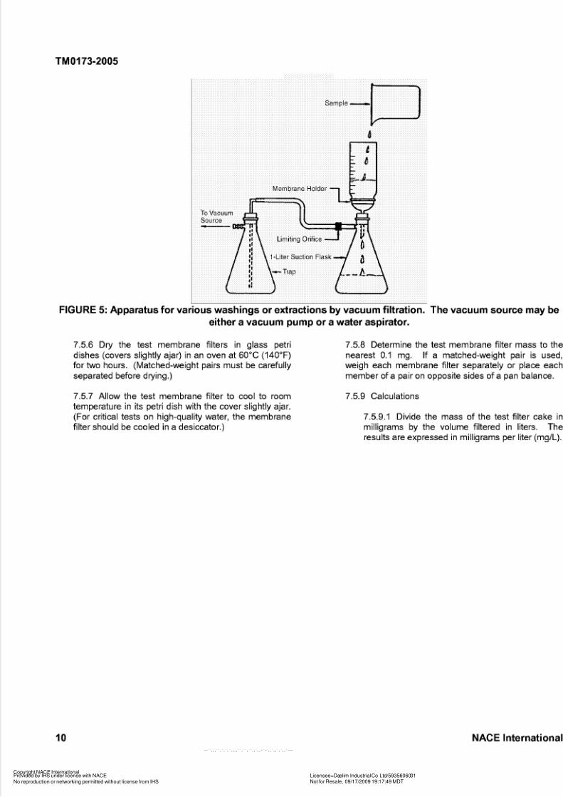
FIGURE 5: Apparatus for various washings or extractions by vacuum filtration. The vacuum s ource m ay beeither a vacuum pump or a water aspirator.
7.5.6 Dry the test membrane filters in glass petri
dishes (covers slightly ajar) in an oven at 60°C (140°F)
for two hours. (Matched-weight pairs must be carefully
separated before drying.)
7.5.8 Determine the test membrane filter mass to the
nearest 0.1 mg. If a matched-weight pair is used,
weigh each membrane filter separately or place each
member of a pair on opposite sides of a pan balance.
7.5.7 Allow the test membrane filter to cool to room 7.5.9 Calculations
temperature in its petri dish with the cover slightly ajar.
(For critical tests on high-quality water, the membrane
filter should be cooled in a desiccator.)
7.5.9.1 Divide the mass of the test filter cake in
milligrams by the volume filtered in liters. The
results are expressed in milligrams per li ter (mg/L).
10 NACE International
Copyright NACE InternationalProvided by IHS under license with NACE Licensee=Daelim Industrial Co Ltd/5935606001
Not for Resale, 09/17/2009 19:17:49 MDT
No reproduction or networking permitted without license from IHS
--``,,,``,`,`,`,,,,``,``,``,,`,,-`-`,,`,,`,`,,`---

5/14/2018 NACE TM0173 - slidepdf.com
http://slidepdf.com/reader/full/nace-tm0173 14/19
TM0173-2005
Table l-Example of Mem brane Filter Test D ata
Sample: Alpha Membrane Filter: 47-mm
(1.8-in.) diameter, 0.45-
pm pore size
Test Pressure: 140 kPa (?IO%) Time for 2,500 mL: 3 min, 36 s
Date: February IO, 1992
Volume (v) Time (t) (s) Av At Rate (AdAt) Comments
(mL) (mL) (4 (mus)
200 15.1 1O0 7.6 13.2
300 23.0 1O0 7.9 12.7
400 31 O 1O0
500 39.1 1O0
600 47.3 1O0
700 55.6 1O0
800 64.0 1O0
900 72.5 1O0
1,000
1,100
1,200
1,300
1,400
1,500
1,600
1,700
1,800
1,900
81 O
89.6
98.4
107.2
116.1
124.9
134.0
143.0
152.1
161.2
1O0
1O0
1O0
1O0
1O0
1O0
1O0
1O0
1O0
1O0
2,000 170.0 1O0
2,100 179.5 1O0
2,200 188.7 1O0
2,300 197.9 1O0
2,400 207.1 1O0
2,500 21 6.3 1O0
8.0
8.1
8.2
8.3
8.4
8.5
8.5
8.6
8.8
8.8
8.9
8.8
9.1
9.0
9.1
9.1
9.1
9.1
9.2
9.2
9.2
9.2
12.5
12.3
12.2
12.0
11.9
11.8
11.8
11.6
11.4
11.4
11.2
11.4
11.0
11.1
11.0
11.0
11.0
10.9
10.9
10.9
10.9
10.9
Section 8: Reporting Test Data
8.1 A report should be written after each series of tests and
should contain the following details:
8.1.3 Descriptions of the test sampling points.
8.1.4 A brief discussion of the test methods used,
noting any variations from the standard procedures.
8.1.5 Tabulation and graphic representation of rate
versus cumulative volume test results (Table 1 and
Figure 4) as described in Paragraph 7.4.6.
8.1.1 A complete description of the water-handling
system tested, including sources, mixtures,
dispositions, and daily volumes.
8.1.2 A flow diagram with line sizes and types (steel,
plastic, etc.).
NACE International 11
Copyright NACE InternationalProvided by IHS under license with NACE Licensee=Daelim Industrial Co Ltd/5935606001
Not for Resale, 09/17/2009 19:17:49 MDT
No reproduction or networking permitted without license from IHS

5/14/2018 NACE TM0173 - slidepdf.com
http://slidepdf.com/reader/full/nace-tm0173 15/19
TM0173-2005
8.1.6 Tabulation of suspended solids test data for 8.1.9 Recommendations for improvements, based on
each sample point in mg/L, ppm, or lb/1,000 bbl. observed results, and recommendations for future test
methods and frequency.
8.1.7 A description of the filtered solids as determined
by one or more methods in Appendix C. 8.2 Test Interpretation and Application
8.1.8 A discussion of the test results and their 8.2.1 This standard presents test procedures that
implications, including comparisons with any prior test should give reproducible results for comparativeresu ts. evaluations. As discussed in Paragraph 1.1, the use of
the results is beyond the scope of this standard.
References
1. C.C. Patton, Applied Water Technology, 2nd ed. (Norman, OK: Campbell Petroleum Series, 1987).
Bibliography
American Conference of Government Industrial
“Threshold Limit Values of Airborneygienists.”)
Contaminants and Intended Changes.” 1970.
ASTM D 3921 (latest revision). “Standard Test Method for
Oil and Grease and Petroleum Hydrocarbons in
Water.” West Conshohocken. PA: ASTM.”’
Barkman, J.H., and D.H. Davidson. “Measuring Water
Quality and Predicting Well Impairment.” Journal of
Petroleum Technology 24, 4 (1972): pp. 865-873.
Dosher, T.M., and L. Webber. “The Use of the Membrane
Filter in Determining Quality of Water for Subsutface
Injection.” In Drilling and Production Practice.
Washington, DC: American Petroleum Institute (APi),‘3’
1957: pp. 169-179.
Eylander, J.G.R. “Suspended Solids Specifications for
Water Injection from Coreflood Tests.” SPE‘4’
Reservoir Engineering 11 (1988): pp. 1287-1294.
Appe ndix A-Microscopic Exam ination
Although microscopic examination is not an absolute
means of identification, it is a useful tool for determining the
nature of the plugging material in injection systems.
Examination by viewing the membrane filter with oblique
incident light or transmitted light may be used.
When large particulate material (>IO pm) is present, it can
be viewed best by oblique incident light. Very small
particulate matter is best viewed using transmitted l ight.
Apparatus:
The microscope used in this analysis typically has an
inclined binocular body, a mechanical stage (two axes), a
multiple nosepiece to accommodate two or more objective
lenses, a substage condenser, and wide-field eyepieces
(usually IOX). Total magnification ranging from 30 or 40X
to 400 or 500X is optimum for almost any identification
application using oblique incident visible light.
I. Microscopic Examination Using Oblique Incident Any of the larger incandescent lamps that provide a suitable
Visible Light light source for this application. These microscope lamps
should be the types that are mounted on an inclining stand
and have a focusing condensing lens. An adjustable iris
diaphragm and ground glass and daylight glass filters are
des rab e.
(’)American Conference of Government Industrial Hygienists (ACGIH), 1330 Kemper Meadow Drive, Cincinnati, OH 45240(’)ASTM International (ASTM), 100 Barr Harbor Dr., West Conshohocken, PA 19428-2959.
(3)AmericanPetroleum Institute (API), 1220 L St. NW, Washington, DC 20005.(4) Society of Petroleum Engineers (SPE), 222 Palisades Creek Drive, Richardson, TX 75083-3836.
12 NACE International
Copyright NACE InternationalProvided by IHS under license with NACE Licensee=Daelim Industrial Co Ltd/5935606001
Not for Resale, 09/17/2009 19:17:49 MDT
No reproduction or networking permitted without license from IHS

5/14/2018 NACE TM0173 - slidepdf.com
http://slidepdf.com/reader/full/nace-tm0173 16/19
TM0173-2005
Materials: Plastic petri dishes
Stainless steel forceps
50 x 80-mm (2.0 x 3.0-in.) glass slides
Petroleum elly or other suitable grease
ProcedUre:
1. Use the dried membrane filter from either the rate
versus cumulative volume test (Paragraph 3.1) or the
suspended solids test (Paragraph 3.2).
2. Prepare a clean 50 x 80-mm (2.0 x 3.0-in.) glass slide
by coating it lightly and evenly with a thin film of grease.
Place the membrane filter on the greased slide. The grease
causes the membrane filter to lie flat and entirely in one
focal plane.
3. Do not use a cover slide in this application because
any contamination on the cover slide may be mistaken for
material retained by the membrane filter. If the membrane
filter is to be preserved for further examination, place the top
of a plastic petri dish over the filter to protect it from
atmospheric contamination.
4. Adjust the incident light source to approximately 40
degrees from horizontal. Examine the membrane filter at
low magnification and then at suitable higher magnification.
Manipulate the microscope stage making two mutually
perpendicular traverses across diameters of the membrane
filters.
5. The oblique incident light will strike the contaminants
on the membrane filter from the side, making differentiation
between fibers, glass, and metals possible.
II. Microscopic Examination Using Visible TransmittedLight
Apparatus:
Microscope and light source are the same as those used in
the microscopic examination with oblique incident light,
except that a IOOX oil-immersion objective lens is useful for
examining and identifying very tiny particulate matter.
Materials:
Stainless steel forceps
50 x 80-mm (2.0 x 3.0-in.) glass slides
45 x 50-mm (1.7 x 1.9-in.)No. 1 cover slides
Immersion oil-index of refraction-I .51
ProcedUre:
1. Use the dried membrane filter from either the rate
versus cumulative volume test (Paragraph 3.1) or the
suspended solids test (Paragraph 3.2). If the membrane
filter is not available, a suitable membrane filter may be
prepared by passing 1 L of fresh sample through a
membrane filter using the apparatus shown in Figure 5.
This membrane filter should be rinsed and dried by the
procedure described in the suspended solids test
(Pa ag a ph 7.5.5).
2. With the forceps, gently float the membrane filter,
sample side up, on a film of immersion oil in the cover of a
plastic petri dish. Draw the membrane filter over the rim of
the cover to remove any excess immersion oil from the
bottom of the membrane filter. Roll the membrane filter
onto a glass slide.
3. Place a clean No. 1 cover slide over the sutface of the
membrane filter, being careful not to trap any air bubbles
under the slide.
4. Adjust the light path from the light source so it is
reflected by the flat substage mirror up through the
substage condenser, through the oil-wet membrane filter,
and into the objective lens. The immersion oil renders the
membrane filter transparent and allows the particles on the
sutface of the membrane filter to be observed.
5. Examine the membrane filter at low magnification and
then under high-powered oil-immersion lens. When using
the drop of immersion oil on the sutface of the slide cover,
carefully lower the oil-immersion objective, using the coarse
adjustment, until the top of objective ust makes contact with
the oil drop. Do this carefully so as not to damage the
objective lens by grinding it into the glass slide. Use the
fine adjustment to bring the sutface of the membrane filter
into final focus.
6. Manipulate the microscope stage making two mutually
perpendicular traverses across diameters of the membrane
filter.
7. The use of transmitted light with the high-powered oil-
immersion lens (total magnification-I ,000X) makes it
possible to identify tiny objects such as diatomaceous earth,
sand grains, slime masses, iron bacteria such as
Sphaerotilus and Gallionella, fresh-water diatoms, and rust
fragments.
Appendix B-Microchemical Spot Test Methods
The spot-testing technique lends itself to quick chemical may be applied. After the sample on the membrane filter
analysis of matter collected on an inert surface (in this case, has been solubilized and dried, the membrane filter is cut
a membrane filter). Spot testing requires that the ion to be into a number of wedge-shaped segments. These
identified be dissolved or partially dissolved before reagents segments are then individually tested for the various ions.
NACE International 13
Copyright NACE InternationalProvided by IHS under license with NACE Licensee=Daelim Industrial Co Ltd/5935606001
Not for Resale, 09/17/2009 19:17:49 MDT
No reproduction or networking permitted without license from IHS
-- ̀ ̀
, , , ̀ ̀
, ̀
, ̀
, ̀
, , , , ̀ ̀
, ̀ ̀
, ̀ ̀
, , ̀
, ,- ̀
- ̀
, , ̀
, , ̀
, ̀
, , ̀
---

5/14/2018 NACE TM0173 - slidepdf.com
http://slidepdf.com/reader/full/nace-tm0173 17/19
TM0173-2005
The cutting blade may leave enough contamination at the
edge of the segment to give a positive test, but the
contamination will not extend into the center of the segment.
The spot tests given in this appendix are for sulfates, silica,
iron, protein, and iron sulfide. NOTE: Various strong
inorganic acids are used as reagents in these tests, e.g.,
nitric and hydrochloric acids. All of these acids are
hazardous and may be harmful in the following ways: (1)
vapors are harmful to breathe; (2) contact with skin may
cause severe chemical burns; (3) acids may cause severe
eye damage; and (4) acids may cause severe damage to
the digestive system if ingested. Eye protection and
appropriate protective clothing must be worn.
I. Sulfates
Materials:
Lead nitrate reagent, saturated aqueous solution
containing 1 mL of concentrated nitric acid per 25 mL of
solution
6N nitric acid
6N hydrochloric acid
ethylene propylene (FEP) coated or lacquered
Stainless steel forceps
47-mm (1.847.) microfiber glass
Prefilter pad
50 x 80 mm (2 x 3 in.) glass slides
47-mm (1.8-in.) plastic petri dish and cover, fluorinated
Black membrane filter (if available)
ProcedUre:
1.
filter using apparatus described in Figure 5.
Filter 1 L of fresh sample through a black membrane
2. Place a 47-mm (1.8-in.) microfiber glass prefilter in a
plastic petri dish and add 1.5 mL each of 6N hydrochloric
and nitric acids.
3.acid-wet prefilter, sample side up, and cover the petri dish.
Roll the membrane filter containing the sample onto the
4. Allow the petri dish to stand for 10 minutes. To aid the
dissolution of the sample, place the petri dish in a 60°C
(140°F) oven during this period.
5.mm (2 x 3 in.) glass slide. Allow the membrane filter to dry.
Remove the membrane filter and place it on a 50 x 80
6. Wet a microfiber glass prefilter with approximately 3mL of lead nitrate. Roll the sample membrane filter, sample
side up, onto the prefilter and let it stand for 10 minutes. Ablack membrane filter should be used for the collection of
the sample.
7. Mount the membrane filter on a glass slide and view it
under low-power (50X) microscopic examination. Use
incident light.
Resu ts:
Sulfate is indicated by white, grainy reaction spots. If it is
necessary to analyze the sample collected on a whitemembrane filter, view the membrane filter by transmitted-
light microscopy.
II. Silica
Materials:
Ben~idine,'~)% ethanol
Ammonium hydroxide, concentrated
7.0-mm (0.28-in.) iltedwire gauzelhot plate
ProcedUre:
1. Filter 1 L of sample using apparatus described in
Figure5.
2. Place the membrane filter on wire gauze and heat
gently over a hot plate.
3.fumes.
Add one drop of benzidine and develop over ammonia
Resu ts:
A blue color indicates he presence of silica.
III. Iron
Materials:
6N hydrochloric acid
6N nitric acid
Potassium errocyanide solution-saturated aqueous
47-mm (1.8-in.) microfiber glass prefilter47-mm (1.8-in.) plastic petri dishes with covers
ProcedUre:
1.
using apparatus illustrated n Figure5.
Filter 1 L of fresh sample through a membrane filter
2. Solubilize the iron in the solids on the membrane filter
using the technique described in the procedure or detecting
sulfates (see Appendix B, Microchemical Spot Test
Methods, I. Sulfates, Procedures 3 through 5). It is not
necessary o dry the membrane filter.
3. While the membrane filter is still slightly damp from the
solubilizing procedure, add one drop of the potassium
ferrocyanide solution.
. . . . . . . . . . . . . . . . . . . . . . . . . . .
(5)NOTE: Benzidine has been listed by the American Conference of Government Industrial Hygienists (ACGIH) as a cancer-causing agent.
14 NACE International
Copyright NACE International
Provided by IHS under license with NACE Licensee=Daelim Industrial Co Ltd/5935606001
Not for Resale, 09/17/2009 19:17:49 MDTNo reproduction or networking permitted without license from IHS
-- ̀ ̀
, , , ̀ ̀
, ̀
, ̀
, ̀
, , , , ̀ ̀
, ̀ ̀
, ̀ ̀
, , ̀
, ,- ̀
- ̀
, , ̀
, , ̀
, ̀
, , ̀
---
5/14/2018 NACE TM0173 - slidepdf.com
http://slidepdf.com/reader/full/nace-tm0173 18/19
TM0173-2005
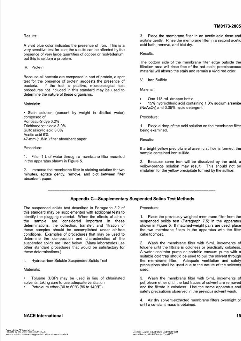
Resu ts:
A vivid blue color indicates the presence of iron. This is a
very sensitive test for iron; the results can be affected by the
presence of very large quantities of copper or molybdenum,
but this is seldom a problem.
IV. Protein
Because all bacteria are composed in part of protein, a spot
test for the presence of protein suggests the presence of
bacteria. If the test is positive, microbiological test
procedures not included in this standard may be used to
determine the nature of these organisms.
Materials:
Stain solution (percent by weight in distilled water)
composed of:
Ponceau-S dye 0.2%
Trichloroacetic acid 3.0%
Sulfosalicylic acid 3.0%Acetic acid 5%
47-mm (1.8-in.) filter absorbent paper
ProcedUre:
1.
in the apparatus shown in Figure 5.
Filter 1 L of water through a membrane filter mounted
2. Immerse the membrane filter in staining solution for two
minutes, agitate gently, remove, and blot between filter
absorbent paper.
3. Place the membrane filter in an acetic acid rinse and
agitate gently. Rinse the membrane filter in a second acetic
acid bath, remove, and blot dry.
Resu ts:
The bottom side of the membrane filter edge outside the
filtration area will rinse free of the red stain; proteinaceousmaterial will absorb the stain and remain a vivid red color.
V. Iron Sulfide
Material:
One 118-mL dropper bottle
15% hydrochloric acid containing 1.0% sodium arsenite
(NaAson) and 0.05% liquid detergent.
ProcedUre:
1.
being examined.
Place a drop of the acid solution on the membrane filter
Resu ts:
If a bright yellow precipitate of arsenic sulfide is formed, the
sample contained iron sulfide.
2. Because some iron will be dissolved by the acid, a
yellow-orange solution may result. This should not be
mistaken for the yellow precipitate formed by the sulfide.
Appendix C-Supplementary Suspended Solids Test Method s
The suspended solids test described in Paragraph 3.2 of
this standard may be supplemented with additional tests to
identify the plugging material. When the effects of air on
the sample are considered important in these
determinations, the collection, transfer, and filtration of
these samples should be accomplished under air-free
conditions. Examples of procedures that may be used to
determine the composition and characteristics of the
suspended solids are listed below. (Many laboratories use
other standard procedures that would be satisfactory for
these determinations.)
I. Hydrocarbon-Soluble Suspended Solids Test
Materials:
ProcedUre:
1. Place the previously weighed membrane filter from the
suspended solids test (Paragraph 7.5) in the apparatus
shown in Figure 5. If matched-weight pairs are used, place
the two membrane filters in the apparatus with the filter
cake topmost.
2. Wash the membrane filter with 5-mL increments of
toluene until the filtrate is colorless or practically colorless.
A water aspirator pump or portable vacuum pump with a
suitable cold trap should be used to pull the solvent through
the membrane filter. Adequate ventilation and safety
precautions shall be used due to the nature of the solvents
used.
Toluene (USP) may be used in lieu of chlorinated 3. Wash the membrane filter with 5-mL increments of
solvents, taking care to use adequate ventilation petroleum ether until the last traces of solvent are removed
and the filtrate is colorless. Use the same apparatus and
safety precautions observed in the previous solvent wash.
Petroleum ether (30 to 60°C [86 to 140"Fl)
4.
until a constant mass is obtained.
Air dry solvent-extracted membrane filters overnight or
NACE International 15
Copyright NACE InternationalProvided by IHS under license with NACE Licensee=Daelim Industrial Co Ltd/5935606001
Not for Resale, 09/17/2009 19:17:49 MDT
No reproduction or networking permitted without license from IHS

5/14/2018 NACE TM0173 - slidepdf.com
http://slidepdf.com/reader/full/nace-tm0173 19/19
TM0173-2005
5. Weigh the membrane filter to the nearest 0.1 mg. 6. Calculate suspended solids as shown in Equation (1):
Record hydrocarbon-free membrane filter mass.
mass after water wash (mg)-mass after solvent wash (mg)
volume of sample through filter (L)hydrocarbon-soluble suspended solids = (1)
NOTE: Oil carryover in the water cannot always be
measured by this technique because oil can pass through
the membrane filter. This method can give only a
qualitative indication of the oil carryover. Other
measurement methods should be used when quantitative
data are desired.
II. Acid-Soluble and Acid-Insoluble Suspended Solids
Test
Material:
15% hydrochloric acid
2. Wash membrane filter with several 10-mL portions of
hot (50 to 60°C [I 22 to 140"Fl) 15% HCI until filtrate is
clear.
3. Rinse membrane filter with distilled water until all traces
of HCI are removed. (Filtrate pH should be >5 as
determined by a suitable test paper.)
4.
2 hours.
Dry membrane filter in drying oven at 60°C (140°F) for
5.minutes in a desiccator.
Cool membrane at room temperature for at least 15
ProcedUre: 6. Weigh cooled membrane filter to the nearest 0.1 mg.
1. Place membrane filter from hydrocarbon-soluble 7. Calculate suspended solids as shown in Equations (2)
suspended solids test in apparatus shown in Figure 5. and (3):
mass after solvent wash (mg) -mass after acid wash (mg)
volume of sample through filteracid-soluble suspended solids (mglL) = (2)
mass after acid wash (mg)
volume of sample through filter (L)acid-insoluble suspended solids (mglL) = (3)
For matched-weight pairs, the initial mass is not neededbecause the lower membrane filter has been subjected to
all liquids and its mass should be the same as that of the
one supporting the filter cake (Paragraphs 2.2.2, 4.2.1, and7.5.8).
16 NACE International
Copyright NACE InternationalProvided by IHS under license with NACE Licensee=Daelim Industrial Co Ltd/5935606001
Not for Resale, 09/17/2009 19:17:49 MDT
No reproduction or networking permitted without license from IHS
--``,,,``,`,`,`,,,,``,``,``,,`,,-`-`,,`,,`,`,,`---