NACA-TR-II54 NATIONAL ADVISORY COMMITTEE FOR AERONAUTICS .../67531/metadc60524/m2/1/high... ·...
52
NACA-TR-II54 NATIONAL ADVISORY COMMITTEE FOR AERONAUTICS REPORT 1154 ANALYSIS OF LANDING-GEAR BEHAVIOR REPRODUCED BY NATIONAL TECHNICAL INFOkMATION SERVICE U,S. DEPARtMENt Of COMIdI:RCE SPRINGfI[LD, ¥A. 22161
Transcript of NACA-TR-II54 NATIONAL ADVISORY COMMITTEE FOR AERONAUTICS .../67531/metadc60524/m2/1/high... ·...

NACA-TR-II54
NATIONAL ADVISORY COMMITTEE
FOR AERONAUTICS
REPORT 1154
ANALYSIS OF LANDING-GEAR BEHAVIOR
REPRODUCED BY
NATIONAL TECHNICALINFOkMATION SERVICE
U,S. DEPARtMENt Of COMIdI:RCE
SPRINGfI[LD, ¥A. 22161

REPORT 1154-
ANALYSIS OF LANDING-GEAR BEHAVIOR
By BENJAMIN MILWITZKY and FRANCIS E. COOK
Langley Aeronautical Laboratory
Langley Field, Va.

National Advisory Committee for Aeronautics
Headquarters, 17Y,_ F Street NW, Washington ,_5, D. C.
Created by act of Congress approved March 3, 1915, for the supervision and direction of the scientific study
of the problems of flight (U. S. Code, title 50, sec. 151). Its membership was increased from 12 to 15 by act
approved March 2, 1929, and to 17 by act approved May 25, 1948. The members are appointed by the President,
and serve as such without compensation.
JEROMR C. HUNSAKER, Sc. D., Massachusetts Institute of Technology, Chairman
D_rLm_ W. BRonx, prt. D.. President, Rockefeller Institute for Medical Research, Vice Chairman
Hotr. JosePH P. AvAus, member, Civil Aeronautics Board. HON..RoBERT B. MURRAY, JR., Under Secretary of Co:nmerce
ALLEN V. ANTIS, PH.D., Director, National Bureau of Standards. for Transportation.
LEONARD CARMICHAEL, PH. D., Secretary, Smithsonian InstitL1- ,, RALPH A. OZSTtE, Vice Admiral, United States Navy, Deputytion. Chief of Naval Operations (Air).
LAt_RENCZ C. CRAInIE, Lieutenant General, United States Air
Force, Deputy Chief of Staff (Development).
JAI_ES H. DOOLIV'rLc-L SC. D., Vice President, Shell Oil Co.LLOYD H_RRISOS, Rear Admiral, United States Navy, Deputy
and Assistant Chief of the Bureau of Aeronautics.
R. M. HAtlCN, B. S., Director of Engineering, Allison Division,
General Motors Corp.WILLIAu. LITTLEWOOD, M: E., Vice President--Engineering,
American Airlines, Inc.
DONALn L. PUTT, Lieutenant Genei'al, United States Air Force,
Commander, Air Research and Development Command.
ARTHUR E. RAYtSO_D, Sc. D., Vice President--Engineering,
Douglas Aircraft Co., Inc.FaA_crs W. REICHELDEarER, Sc. D., Chief, United States
Weather Bureau.
THEODORE P. Wmnttv, Sc. D., Vice President for Research,
Cornell University.
HUOH. L. DsYnz_t, PH.D., Director
JOHI_" W. CROWLET, JR., B. S., Associale "Director for Research
JOHN F. Vtc'roav, LL. D., Executive Secretary
EDWARD H. CHAMBERLIN, Executive Officer
HEART J. E. RIND, D. Eng., ]Jirector, I_ngley Aeronautical Laboratory, Langley Field, Vs.
SMITh J. DRFRANC =, D. Eng., Director, Ames Aeronautical Laboratory. Moffett Field, Calif.
EnWABD R. SHARP, SO. D., Director, Lewis Flight Propulsion Laboratory, Cleveland Airport, Cleveland, Ohio
LANGLRT ARRONAUTICAL LABORATORY, AMES AERONAUTICAL LABORATORYj LEWIS FLIGHT PROPULSION LABORATORY,
Langley Field, Vs. Moffett Field, Calif. Cleveland Airport, Cleveland, Ohio
Ctmducl, under unified control, for all agencies, of scientiYic research oH the fundamental problems of flight

CONTENTS
SUMMARY ...............................................................INTRODUCTION .........................................................
SYMBOLS ....................... : .........................................
MECHANICS OF LANDING GEAR ......................................
Dynamics of System ...............................................Forces ill Shock Strut .................................................
Hydraulic force ....................................................Pneumatic force ...................................................
Internal frictiou force ..........................................
Forces on Tire ............................. •.......................
EQUATIONS OF MOTION ............................................
.Motion Prior to Shock-Strut Deflection .................... . ........
.Motion Subsequent to Beginning of Shock-Strut I)cflec[iovi .... • .....
SOLUTION OF EQUATIONS OF .MOTION ...........................
Nmnerical Integration Procedures__: ...................................Use of Tire Force-Deflection Characteristics .............................
Effect of Drag Loads ...............................................EVALUATION OF ANALYSIS BY COMPARISON OF CAI,CULATED
RESULTS WITH EXPERIMENTAL DATA .........................
Normal Impact ......................................................
Impact With -Tire Bottomittg ....................................PARAMETER STUDIES ..................................................
Representation of Tire Force-Deflection Characl(.risvic,_ __ . , ...........
Normal impact ....................... : .................
hnpact with tire bottomiug ......... _ ......................Effect of Orifice Discharge Coefficient ........................................
Effect of Air-Compression Process .......... : .....................SIMPLIFICATION OF EQUATIONS OF .MOTION ..........................
Evaluation of Simplifications ................... " ..................Generalized Treatment_ .......................................
Equations and solutions ....................................
Applicability of sohltious ........... •..........................SUMMARY OF RESULTS AND CONCI,USIONS ......................
APPENDIX A--NUMERICAL INTEGRATION PROCFDURI':S .......
Linear Procedure ........................................
Quadratic Procedure .........................................Runge-Kutta Proeech,re ................ ........... _ ........
APPENDIX B--SOURCE OF EXPERIMENTAL DATA ...................
Equipment .... : ...............................................
Test Specimen ................................... : ......... . ............Instrumentation .......................................................
REFERENCES ......................... .................................
BIBLIOGRAPtIY ....................................................... :
Ill
Paffe
l
22
3
3
4
6
7
7
89
10
12
12
12
13
13
1314 ""
14
14
17
20
20
20
22
2425
25
25
29
31
3fi
36
3841
42
42
42
42
44
44


REPORT 1154
ANALYSIS OF LANDING-GEAR BEHAVIOR l
By BExJxxntn.._[ILWITZKY and FrAxcls E. {'oak
SUMMARY
This report presents a theoretical study of the beha_'ior of the
coneentional type of oleo-pneumatic bzndin9 gear during the
proce.Qs oJ landing impact. The ba._ic analy._'i._ is pre._ented in
a general.h,'m and treat._" the motions _ the landing gear prior
• t- and .,.ub.;.equent t,, the beginning of._hock-._trut deflection, b_
the analy._is aj the Jir.,'t ph.ase of the impact the lamling gear i._
treated a._" a xin9le.ulegree-ofzfreedom. ._y._tem in order t, ,leter-
m ine the o,,ditioa._ ,,f m,,ti,,n at the in.,'tant ,,[ "in itial ._h,,ck-._trut
,#flection, after which in._tant the landi,9 gear is cou.side?ed as
a ._y._tem witl_ tu, o degree._ qffreedom: The equations Jar the
ta'o-degree-,!f-.h'eedom ._y.,.tem eon_ider such .factors as the
hydraulic (eel,city ._.quare) re._L_tance o.[ the orifice, the .force._
due to air compre._._i,n and internal fi_iction in the. "_hock strut,
the nonlinear.f,,'ce-deflectlon eharacteri._tie.¢ qf the tire, the wing
I_ft, the incli,atian ,!fthe lamling gear, and the _.ffeet.; of wheel
._pin.-up" drag l,_ad._.
The applicability of the analy.,'i._ to actual landing years has
been incest_.qated for the particular ca._e off a vertical landing.!
9ear in the abset_ce oJ drag loads by comparing calculated
re._ults with experimental drop-te._t data f,r impacts with and
without tire bottoming. The calculated behacior of the landing
goat' wa.,'.found to be it!. good ogtvement with the drap-text data.
Studie.s haee al._o been made to determ ine the. effects of raria-
tion_ in such imrameters a.s the dynamic force-dtflectbm
characteristics oJ the tire, the or_ee discharge coefficient, and the
polflropic ex.ponen.t .for the air-eompre,_._i,,n proce._s, which
might not be kn.own accurately it_ practical de_'ign problems.
The study of the effect.; off wu'iations in the tire characteri._'tic.*
it,licate._ that in the ca._e _( a normal impact without tire
bottom i,9 rea._onable _vu4ati,,ns it_ the Jarce-deflecti,m character-
;_ties have ,,nlya relatitvly small effect on the e_leulated behacior
,,f the landing t.lear. Appr,#imati,g the rather complicated
.[,rce-deflecth,_ charaeteri._ties ,'f the actual tire by Mmpl(fied
e_'p,mential ar linear-._egment cariation._ appear.s to be adequate
.[,r practical purp,.,'e._'. Tire hy.,tere.,'i._ wa._ f_mnd to be
relath'ely unimportatd. In the ca._e aJ a _evere impart inroleiny
tire bott,,niu9, the .u.,'e ,:[ ,_implifi,,,I esp,,nentlal an,I linear-
n _ul_,r_.des N?,.CA TN 2755, "3.n:dysis c,r L-,,ndtnlz.( ;e:e,r B_,ha',i.r" by B_,nj;_tllln 51 ilwil;_ky :rod I"r:_nt'is E. ('..k. 1!1:,2.
_$7 g 4¢,--,fi 4------- 1
segmet_t approximation.," to the actual tire .[oree-.,hfl, cth,_
characteri_'tics, which neglect the effect.s" oJ tire bottoming,
although adequate up to the in.,'tant of bottomi_g,.fail.; to indic, te
.the pronoun.cad increa.,'e in landing-gea.r l,ad that r,..sult._ fr,,m
bottomin.g of the tire. The-u._e of exponential a,d li,_.r-
segment appro_rimation,_ to the tire character;._th'._ which t,_t',-
into account the increa._ed .vtiJfne._s ,,f the tic, ,'hieh r,.,alt., /'_,,,,,
bottoming, hawecer, yiel,l,_ good re._ult.*.
The study q[ the importa_ee o.f the di._charge e,t.ffic#,t ,,J" th,
o!.ifice iadicate._ that the magnitmle of the di._charge e,,,-flic;,,t
has a marked _ffeet on the calculated behari,r _ the la,,I;_,!t
gem': a decrease in, the di.,'charg_ e_,e.l_c;e,t (or the pr,,d,_et ,:t th,
discharge coeffieie,t an,I the net i,riKce area) re._d/.,. 'i.. ,t,
appro.rimately proportional ittcreaxe in the ma.rimum _tpp, r-ma._'s acceleration..
The study of the _mporta,ce q( tl_ air-o,mpr*._.sb,, pr,c_._._"in. the shock strut indicate.; that the air .spri,yin 9 ;._ ,.f ,,,l!l
•mlnar ._iynificance throughout mo._t q[ the impact a,,I tl,,tt
variotion._ in, the effectire p,,lytropic exponetd , b, tw,.e_, th,_
i.,.othermal value of I.O and the near_,habatic r,da, ,:[ 1.3 h,tc,
,nlya seeon,h_r!/ effect ,,u the calcahtte,I b_h_t_'ior ,!f the btn,/i,,t
9ear. Et'et_ the as.sumpti,n ,,J c6q,_.tant air pr_.._.._.ure in the .,true
equal ta the initbd pre._._are, that i._. n=O, yields [a;rly y,o,I
results whichamy be adequate.tar ma,y practical p_trp,,.,e_.• It, a_hl.itiou to the ,nora e_'act treatment, an i,ce.,.tlyat;,m ha._
been .made to determi_e the exbnt to u'hich th.e ba.slc eqaatian._
q[ motion ca_ be simplified and still yield acceptable r_.,ults.
TId._ sturdy indicates that, Jot' -many practical p_upo.ees, the
air-pressure force it_ the shock _trut eau be completely ,egl_ct_d.
the tire.force-deflection relation._hip can be assumed to be limar,
and the lower or utmprung ma._._ can. be ta]cetl, eqmd to :,ro.
Generalization. of the equation._ of .mot.iot_ for this .,'im pl(/i_,l
._ystem shows that the be.harior nf the ,_'!l._tem is completdy
determined by eke magn.itude of one lutrameter, na,i,ly the
dimensionle._s in_tial-veloclty parameter. Solutl.n.s <( th._'c
yen_.rallzed equations are presented "i_ teems oJ dimen._io,hss
variables.for a wide range oJ latulitql.ujear and imlmct paramet< rs
which may be useful .for rapidly est_mati,_.l lamli_g-gear
petJ.rmance it_ preliminary design.

2
INTRODUCTION
The shock-absorbing characteristics of airplane landinggears are normally developed largely by means of extensivetrial-and-error drop testing. The desire to reduce the ex-pense and time required by such methods, as well as to pro-vide a more rational basis for the prediction of wheel-inertiadrag loads and dynamic stresses in flexible airframes durblglanding, emphasizes the need for suitable theoretical methodsfor the analysis of landing-gear behavior. Such theoreticalmethods should find application in the design of landinggears and complete airplane structures by permitting
(a) the determination of the behavior of a given landing-gear configuration under varying impact conditions (velocityat contact, weight, wing llft, etc.)
(b) the development of a landing-gear configuration toobtain a specified behavior under given impact conditions
(c) a more rational approach to the detelTnination of wheelspln-up and spring-back loads which takes into account theshock-absorbing characteristics of tile particular landing gearunder consideration
(d) improved determination of dynamic loads in flexibleairplane structures (luring landing. This problem nmy betreated either by calculating the response of the elastic sys-.tem to landing-gear forcing functions determined under theassumption that the airplane is a rigid body or by the simul-taneous solution of the equations of motion for the landinggear coupled with the equations representing the ad(litionaldegre_ of freedom of the structure. In many cases the formerapproach shouhl be sufficiently accurate, but in someinstances, particularly when the landing-gear attachmentpoints experience large displacements relative to the nodalpoints of the flexible system, the latter approach, which takesinto account the interaction between the deformations of thestructure and the landing gear, may be re(tuired in order torepresent the system adequately.
Since many aspects of the lan(ling-impact problem are sointimately connected with the mechanics of the landing gear.the subject of landing-gear I)ehavior ha.s received analyticaltreatment at various times (see bibliography). Many ofthe earlier investigations, itx order to reduce the mathematicalcomple.,dty of the analysis, were limited to consideration ofhighly simplified linear systems which have little relation topractical landing gears. Some of the more recent papersconsider, with different degrees of simlflification, more real-istic nonlinear systems. The present report represents anattempt at a more complete analysis of the mechanics ofpractical landing gears and, in addition, investigates the im-portance of the various elements which make Ul> the landinggear, as well as the extent to which the system can be reason-ably simplified for the purpose of rapid analysis.
The basic analysis is presented in a general form and takesinto account such factors as the hydraulic (velocity square)resistance of the orifice, the forces due to air compression andinternal friction in the shock strut, the nonlinear force-detlection characteristics of the tire, the wing lift, the inclizm-tion of the landing gear and the effects of wheel sl)in-ul) dragloads. An evaluation of the applicalfility of the analysis toactual landing gears is l)resented for the <.ase of a verticallanding gear in the absence of dL'ag loads I)v COml)aring cal-culated results with drop-test data.
REPORT l154--NATIONAL ADVISORY COMMITTEE FOR AERONAUTICS
Since some parameters, such as the dynamic force-deflection characteristics of the tire, the orifice discharge
coefficient, and the polyt topic exponent for the air-compressiouprocess, may not be accurately known in practical designproblems, a study is made to assess the effects of variationsin these parametem on the calculated landing-gear t)ehavior.
Studies are also presented to evaluate the extent to whichthe dynamical system can be simplified without greatly im-pairing the validity of the calculated results. In addition t_the investigations for specific cases, generalized solutions forthe behavior of a simplified system are presented for a widerange of landing-gear ant[ impact parametet_ which may beuseful in preliminary design.
SYMBOLS
+,4+ pneumatic areaAh hydraulic areaA, area of opening in orifice l)latcAt internal cross-sectional area of shock-strut inmq
cylinderA_ external cross-sectional area of shork-strut inLwr
cylinderAp cross-sectional arcs of m(,tering pin (w L't)d b
plane of orificeA, net orifice areaCd orifice discharge coefficientd overall diameter of tin,
F. pneumatic force in shock stru!Fh hydraulic force in shock strmFI friction force in shock strutFs total axial shock-strut" force};'t nornml force on upl)er l)earing (at tached to ira.,
cylinder)F.+ normal forte on lom, r bearing (att a(.h(.d t<,out,.
cylinder)
F v+ force normal to axis ,)f sho,'k stru.t, apl>lit'd ,axle
Fv_ v'ej'tit'al force, applied at axh'F., hot'izontal force, applied at axh'FR, rcsuhaut force, el)plied at axh'
_, force parallel to axis of shock strut, al)l)lied 1tire at grouml
.h:vs fort'e uormal to axis of shock strut, al)l)liedtire at ground
F% vertical force, applied to tire at groumtF,t t hovizontal force, apl)lie<l to tin' at gt'ouudFrs resultant force, apl)licd to tin' at graundg grak'it ational coustantKL lift fa<'tor, L/IVL lift force
It axial distance between ul)p('x' and h)wcr brarin_for fully extended sho_'k strut
1+ axial distance l)t,tween axle aml hnvet' b'tttil(attached to outer cylimh'r), fur fully c"h,n.ded shock stL'LLt
o,b,m,r constants corresl)onditLg t- tilt, 'rut'i[)us rrgitt_,t)f the tire-<h,lhwti(m pt'orcss
a t t'OLUltintq] <'ons| Lilt|, Hd
lit t ('oln])int,d t+.onslanl, mr/r
+t polytt'ol)i[' t,Xl)<_nent for ait'-vttlltl)rl*ssh_n l)m+'*̀+in shork slt'ul

ANALYSIS OF LANDING-GEAR BEHAVIOR3
R
p,
p_
QF.
8
T
t
T
I,,
T'v
T'u
11"
Jr,w,.Xs
?LL
0
_Ys
Reynolds numl)4,r
air pressure ill upper chamber of shock strut
hydraulic pressure in lower ellamber of shockstrut
volumetric rate of discharge througli orifice
radius of deflected tire
shock-strut axial stroke
wheel inertia torque reaction
time after contact
time after beginning of shock-strut deflection
air volume of shmck strut
polar moment of inertia for wheel assemblyabout axle
vertical velocityhorizontal velocity
total dropping weight
weight of upper mass above strut
weight of lower mass below strut
horizontal displacement of lower mass from
position at initial contact
vertical displacement of upper mass from posi-
tion at initial contact
vertical displacement of lower mass front posi-
tion at initia.1 contact
dimensionless upl)er-nl,ass displacenl,ent from
position at initial contactdimensionless lower-mass displacement from
position at initial contactdimensionless shock-strut stroke, at-u:
dimensionless time after contact
angle 1)etwcen shock-strut axis aml vcrti('al
"d;" <t_shock-st rut effectiveness, ,,
• ._l I mazO'max
'ah" d_l
landing-gear effe('t iveness, " U_1 mlix ]max
time interval in numerical integral ion procedures
coefficient of friction between |ire Illl,tl runway
eoeffleient of friet iozi for upper I)earing (at tached
to inner cylinder)
coefficient of fi iction for lower bearing (tit <ached
to outer cylinder)
mass density of hydraulic fluid
angular acceleration of wheel
vertical axis, positive downward
horizontal axis,'l)ositive rearward
at instant of initial contact
at instant of initial shock-strnt deflection
at instant of wheel Slfin-u p
maxiluunl vahie
IZ
_t
P
Axes:
Z
Z
Subscripts:
0
T
71ttl._
Notatiou:
I( )[ absolute value of (.)
( )* estimated value of ( )
The use of dots over s.wul)ols indicates difh,rent iat i(m wit h
rcspcet to time t on" T.
Prime nilll'kS lad<rate dil]'erentiatiolt with resl)rvt to
(linwnsionh,ss lime 0.
MECHANICS OF LANDING GEAR
DYNAMICS OF SYSTEM
In view of tll,e fact, that lan,ling-gear performance appeat_
to be relatively unaffected by tile elastic deformations of
the airplane structure (see, for example, refs. 1 and 23 par-
ticularly since in many eases the main gears are loeat,.d
fairly close to the nodal points of tit<' fund, mental I)emlinz
nmde of the wing, that part of the airplane whiclt acts ell
given gear can generally be considered as a rigid mass.
As a result, landing-gear drop tests are often rondurted in
a jig where the mass of the airplane is represented by a
concentrate<[ weight. In particular instam'es, however, such
as in the case of airplam,s having large com'entraled masses
disposed in an outboard position in the wings, especially
airplanes equipl)ed with bicycle landing gear. ,onsiderati(mof the interaction between the deformation, of the airplane
structure anti tim landing gear may be necessary to ,el)re-
sent the system adequately.
Since the present report is concerned primaril.v with themwchanics of tlw landing gear, it is assumed in the analyst,
that the lan, ding gear is attadwd to a rigid mas_ whirh has
freedom only in vertical translation. The gear is assumedinfinitely rigid in bcmling. The comb<nation< of airphme
and lan, ding gear considered theft, fore rtmstitutes a svsti,ln
havin, g two degrees of freedom (see fig. 1 (a)> as tit'[tiled ]),t,-
tlw verticM displaeenl,ent of the upper mass aml the verti,'al "
displaremcnt of the lower or tmsprtmg mas,_, which is .risethe tire dcflc('tion. The. strut stroke ._ is deiermim.d hv
the difference between thc displaremetlts z, aml z2 and. in
tlw ease of inclined gears, by tit<, angle ¢ I)etween," tile axis
of the strut and the vertical. For in,tithed gears. (.onq)ressi<lli
of the shock strut produces a horizontal disl)lacemvtH of l l,,
axh, .r.,. Ft'om consideration, of the kinematirs of tim svsletll
it <'all Im s.,ell tllat s Zi--Z2 alld.r_.=._' shl- ¢=(-_i--.._2} fan ¢.
COS 9
hi. the analysis, external lift forces, eairresliouding to the
aerodvlialnic lifl, arc a.,,isulned to act on the s,vSlcln lhroligh-
out the impact. In addition to lhc verticlll forvi,s, arhitrary
drag loalls arc considered to ai't between the tire and llu,
ground.
Tim svsteln treated ill lilt' llnalvsis inay l lieleforc lit, COil-
sidcred to represent either a landing-gear droll lest in a jig
where wing lift and drag loads arc sinl,ulaled, or the hlnding
iml)aci of a rigid ah'plam, if rotational motions are n,egleeted. -Rotational freedonI of tile airphlne, wll,,re sign, ifiran, t, inilly"be taken into account approxinlati,ly liv.llSe Of all apl)ro-
priate effective nlass in the alialysis.
I4"igill'e 1 (I)) shows a sebematicrcpresenlaliou of a typiriil
oh,o-pneunlatic shock strllt used ill Anlcrican practice. Tim
lower clianilier <)f ilte strut conlains hydraulic fluid alill tile
upl)er el<anther contains air under i)ix,Ssilrc. The Oilier cyl-
inder of flue strut, whicli is alltivhed to the tipper nlilss.
cotltains a I)erforated tul)e whivh supports it plate with II
sulall orifice, tlu'ough which llle hydi'au_ie fluid is forved to
flov," at high velocity its a result of the teh'scOliUig of the
strut. Thp hydrauliv pressill'e ilro I) acl'OS_ lhe Ol'illt'e Ihu_
produred resists llie vlo,_ure of Ihe strut, ;llld the turlllii['m, _
crealed I)l'ovide_ il powerful liiellllS of lill_oi'llhlg alid dis-
sipaling a large parl of tile iliipli('l eliergy. Ill _l)lile slt'llls
I lie orillcl, ari,il i_ cOlislillil ; whl,reils, in el her ('il#,e_ il iliPleriilg

4 REPORT l154--NATIONAL ADVISORY COMMITTEE FOR AERONAUTICS
\\
\
\
\
\\\
pin or rod is used to ('olltro| the size of the orifice and govern
tile performalwe o1" the slrtlt.The compressioll of the strut prodl|ces all. in(Teas¢' ill lh('
air pr(,_slll-e which also l'esists t|lt' elosuro of the slru|. ]1_
figtlrt. I (b)ph la,presellls the oil pl'eSstlre ill th(' lower chol|ll)(,r
and p_ rol)rt's_'litS the air I)r('ssul'{ ' ill lit(, Ul)l)cr ('}|an/b(,r.In additiml [e tile hydraulic rcsistan('c and air-l)l't'SSlll'('
fol ('('s, interlaal befll'il|_._ fri('t ion also ('ontrii)tltes fol'ces whi_']l
('an appreciably affect tit,, I)(,havior of the strut.
The forces crvated within the strut impart an aeceh, ration
to the upl)i'r mass and also t)rochwc an a(.eeh, ralion of d.'
lowt.r mass and a deflecliol), of Ii., ti.'_'. Figure 1 (c) slmws
the Imlan(.. of fo..c.t,s and r(,a('lions for tlw whys,l, the iluu,r
cyliluh.r, and tlw Otlfl,l' (.ylimh,r. It is ('h,ar that tim S|l'lll
and the tit:' mutually infhwnce tlu' I)(,havi.r of ore, auotl.t,r
aml must I)e ('o]mi(lere(I simultaneously in amdyzing lht' Sysl ,'Ill.
FORCI_ IN SHOCK STRUT
From consideration of tit(, |)l'l'SStll'eS acting in thc sl..'k
stt'ot it ('au Iw readily s.cn from figure 1 (b-) that tl.' lotal
axi,l force due to hydraulic resistance, air c{m!l)r,'ssi(m, au_d
Iwaring fri('tioll call 1)c _,xl)resscd by
whi,r¢
.Ii
.|p
• , i /i_,b._ = ph(A,--.-l,,) + p,,(. 1:--. 1,) -t- p,,. l,,-r- ,
inh,mml (.ross-st,('lional a,'_'a of i,ul_,r ('vliml(q'
(,xl.(,rn0] ql'OSs-se('|ional al't,Ii (}'f illlllq" ,.vlimh, r
(.rnss-s(q'lio}ml ar_,a of im, tcriltg pin -r r(.l i,). l)lam'
or orifi(,_,

ANALYSIS OF LANDING-GEAR BEHAVIOR
/
Forces on outer cyhncier / . ll°_- / / /_ _ / ' //
; \\'_O // //
\ " ,i--I
/// _ "
/ /,,-;: .,-,>>, . / ,," />, -// ,_,\, / V
/- \- " / /",._, I /# _ /
,/ ,'/ ," ./ ]",,,/ "_ _ %1,// , ,/F_ / ./ . .
," / ," . %_I/X ,/ '-"
" " " / "° \ "\'k . .,'cos
• / /
Forces on wheel
(c) Balance of foree,_ and reaelJou_ for landing-gear components.
FI_URt: l .--(',onehlded.
_$7S46--5{--2

6
This expression can also be written as
Fs = (ph-- P.) (A,-- Apt -4-peA, + F s
= (p_--p,)A,+p,A.+ F_
=Fh-4-F.+ F t (1)
where
p,--p, pressure drop across tile orifice
zl, hydraulic area (AI--Ap for tile strut shown in fig. 1)
A, pneumatic area (At for tile strut shown in fig. 1)
In this report the terms (p_--p,).-l, and p,A, are referred
to as hydraulic force F_ and pneumatic force F,, respec-
tively. For the strut shown in figure 1, the h)/thaulic
and pneumatic areas are related to tile strut dimensions as
previously noted. In the case of Struts having different
internal configurations, the hydraulic anti pneumatic areas
may bear somewhat different relations to the dimensions
of the strut. In such cases, however, consideration of the
pressures acting on the various components of the strut
shouhl permit these areas to be readily defined.
Hydraulic foree.--The hydraulic resistance in the shock
strut results from the pressure difference associated with the
flow through the orifice. In a landing gear the orifice area
is usually small enough in relation to tile diameter of the
strut so that the jet velocities anti Reynolds numbers are
sufficiently large that the flow is fully turbulent. As a
result the damping force varies as tile square of the tele-
scoping velocity rather than linearly with the velocity.
Since the hydraulic resistance is the major component of
•tile total shock-strut force, viscous damping cannot be
reasmlably assumed, even though such an assumption
would greatly simplify the analysis.
The hydraulic resistance can be readily derived by making
use of the well-known equation for the discharge throl,gh
an orifice, namely,
O=C_A.12 (ph-.po )
where
0 volumetric rate of discharge
C_ coefficient of discharge
A. net orifice area
ph hydraulic pressure in lower chamber
p. air pr'essure in upper chamber
p mass density of hydraulic fluid
From considerations of cent]natty, the vohunetric rate of
discharge can also be expressed as the product of the teh'-
scopil!g velo,.ity _ and the hydraulic area ..1_
Q= Ah._
Equating the preceding expressimls for tin' discharge per-
hilts writing tilt, follmving stall)h, vquatiou for the pressure
dro I) across the orifice
p .-1,,2_ 2
p,,-- p,,= 2(Cd -i_,)_
Tilt' hyd,'aulic rcsista_we ?'h due to the tdeSVOl)iug of tlwstrut is given 1)3 the product oi" thc difrer.,ntial l)/'ossurc
REPORT l154--NATIONAL ADVISORY COMMITTEE FOR AERONAUTICS
ph--p, and the area -th which is sulljceted to the hydraulic
pressure, as previously noted. Thus
F__ PAJ a _2 (2)- 2(C---_A.)_
Equation (2) can be nlade applicable to both tile compres-
sion and elongation strokes by introducing tlle factor 7;
to indic.ate file sign of tile hydraulic resistance; thus
k pd_ a?k----- i_..! 2(C,A.)_ ._a 2at
Tile net orifice area d,, may be either a vonstant or, wheu a
metering pin is used, can vat" 3" with strut stroke; that is.
A.=Ao--Ap=A.(s), where Ao is the area of the opening it(
the orifice plate anti Ap is the area of the metering pin in tile
plane of the orifice. At the present time there appears to be
some tendency to elinfinate tile metering pili and use a con-
st'axkt orifice area, particularly {or hlrge airphlm,s, in which
case A.=Ao. In tile general ease, the orili.'e discharge
coefficient nfight 1to expected to vary somewhat during an
intl)act Ilecause of changes ht tit(, size amI vontiguration of
the net orifice area, changes in till' exit conditions on tlw
downstreant facc of the orifice due to varhlt ions in tht, anlounl
of hy/h'aulie f]llid above tilt' orifice phlte. (.hanges ill the t,nll'y
conditions due to variations_ in the h,ngth of t]w flow clmtnbcr
upstream of tilt, orifice, and bc¢.ause of variations in the
Reynohls number of the flow. so tlmt, in general. Ca= Cai._. 12).
Although the imlivi(lual effects of these fa,.Io,'s on the dis-
charge coefficients for orifices in shock struts |tare uot been
evahlated, Ilwre is sonle experimental evidence to indicate
apprecialile variations of the dis('harg(. ('oetilt'ient during
in(pact, particularly in tilt, east, of struts with metering pins.
It might lit. exl)ected that such v,lriations wouhl l)(, ('ml-
sidcrably smalh, r for gears having )l orals(anti orifit'(' arva.
lit orth'r to (,valuate the prl,,.ision with whi,.ll Ill,, orifi,',,
dist'harge (,oeliicient has to It(, known, a bri(,f study is
pres(,nt(,(I in a suI)s(,<luent s(,cti()n which shows the (,ffe('l of
Ill(, discharge coeflit'it,nt on (lie ('alculated I)(,havior (if a
landing gear with n vonstant orifice area. un(h'r th(' assump-
tion that th(, (lisehargc eoel_cicnl is constant during the
in(pact.
The foregoing (liscussion has been concerne(I I)rinmrily wit h
the conlpression stroke of the shock strut. .Most struts
ineorl)oratc some forln of pressure-opt'rat_'d l'l,botnltl ch(,ck
valve, sometimvs called a suul)ber valve, whi('h co,u(,s into
action aft,.r the nlaxiutlun st rokc ]Ills lit,ell attained alul (,loses
off the main critic(, as soon as the _t,'n( begins to clongat(,, so
that tilt, fluid is forced to ret u,'n to tilt, lower vhanll)(,r through
small passages. Tit(, action of lilt' snul)l),,r vlllvc intro,lu<.,,s
grt,atly increased hvtl,'aulic resistan('c t<) <lissilml(, the cnt,rgy
stored in the strut in the fo,'ul of air l)t(,s._lu'e aud to l))'(,v(,ut
excessive rei)oun<l. The lu'odut't C,,A. to I)(, used in ,,quation
(2at (luring tilt, (,longs( ion strok(, is g,,u(,rally un('vrtain. Who
(,xa('t area ..1. (htn'ing t'longatlon is usually soln(,wllat (lifli,,uh
to (h'|ill(' from tilt' g,,onwlry of th,' slt'llt siur'e ill lUalty I'llg,('S
the numl)(,r of conn(,('l ing l)a_sag(,_ vau'it,s wit h sl t'ol.:t' and the

ANALYSIS OF LANDING-GEAR BEHAVIOR
leakage area around the piston may be of the same order ofmagnitude as the area of the return passages. Furthermore,the magnitude of the orifice discharge coefficient, and even
possibly the nature of the resistance, are questionable due to
the foanfing state of the returning fluid. Fortunately, the
primary interest is in the compression process rather than
the elongation process since the maximum load always occursbefore the maximum strut stroke is reached.
Faaumatic forca.--The air-pressure force in the upper
chamber is deternfined by the initial strut inflation pres-
sure, the area subjected to the air pressure (pneumatic area),
and the instantaneous compression ratio ill accordance
with the polytropic law for compression of gases, namely
pay'----- Constant, or
Vo
P"---- P°o
where
p° air pressure in upper chamber of shock strut
p.o air pressure in upper chamber for fully extended strutr air volume of shock strut
v0 air volume for fully extended strutginee the instantaneous air volume is equal to the difference
between the initial air volume and the product of the stroke
and pneumatic area A_, pa=Pao_,,Vo---_-_)The force due
t
to ihe air pressure is simply the product of the pressure and
the pneumatic area:
( ,'0 VF,= p_oA, \_] (3)
In the preceding equations, the effective polytropic
exponent n depends on the rate of compression and the rate
of heat transfer from. the air to the surrounding environment.
Low rates of compression would be expected to result in
values of n approaching the isothermal value of L0; whereas
higher values of n, limited by the adiabatic value of 1.4,
wouhl be expected for higher rates of compression. Tlw
actual thermodynamic process is complicated hy the vioh, nt
mixing of the highly tm-bulent effiux of hydraulic fluid and
the air in the upper chamber during impact. On the on,++
hand, the dissipation of energy in the protluctiou .of turl)u-
lenee generates heat; on the other hand, heat is absorbed I)v
the aeration and vaporization of the fluid: The effect of this
mixing phenomenon on the polytropic exponent or on the
equivalent air volume is not clear. A limited amount of
experimental data olitained in drop tests (refs. 3 and 4),
howevei', indicates that the effective polytropie exponent
may be in the neighborhood of 1.1 for practical cases. A
brief study of the importance of the air-compression process
anti the effects which different vahws of n may have on the
calculated behavior of the lauding gear is presented in a
sul)sequeut section.Internal friction force.--Iu the literatm'e on nmchine tie-
sign the wide range of conditions m.le,' which frictionalresistant,' can occur I..tween sliding sm'faces is generally
classified in three major catcgories, nam,,ly, friction l)etween
dry sm'fact,s, friction bel_x,,cn iml)t'rfectly lubricated surfi,',,s,
and friction belween l)*'rfv,'dy ]uhrieated surfaces. In the
7
case of dry friction, the resistance depends on the physical
characteristics of the sliding surfaces, is essentially propor-
tional to the normal force, and is approximately independent
of the surface area. The coefficient of friction _, defined as
the ratio of the frictional resistance to the normal force, is
generally somewhat greater under conditions of rest (static
fl'iction) than under conditions of sliding (kinetic frictiou).
Although the coefficient of kinetic friction generally de-
creases slightly with increasing velocity, it is usually con-
sidered, in first approximation, to be intlepen<leut of vehwity.
If, on the other hand, the surfaces are completely sepm'atcd
by a fluid film of lubricant, perfect luhricatiou is said to exist.Under these conditions the resistance to relative motion
depends primarily on the magnitude of the relative velocity.
the physical characteristics of the lubricant, the area, aml
the film thickness, and is essentially independent of thenormal force and the characteristics of "the sliding surfaces.
Perfect lubrication is rarely found in practice but is most
likely under conditions of high velocity aml relatively small
normal pressure, where the shape of the sliding surfaces is
conducive to the generation of fluid pressure by hydro-
,lynamic action. In most practical applications involvinglubrication, a state of imperfect lubricatiott exists and th,.
resistance phenomenon is intermediate, between that ot dry
friction and perfect lubrication.
In the case of landing-gear shock struts, the eoll, liti,m,_
under which internal friction is of concemi u_.ually involvr
relatively high normal pressures and relatively snmll sliding
velocities. +Moreover, tit(, usual types of hydraulic th,id
used in shock strolls have rather poor lubricating properties,
and the slmpe of the hearing surfaces is generally not con-
ducive to the genel;ation of hydrodynamic pressures. It
wouhl therefore appear that the lubrication of sl_ock strut
bdarings is, at best, imperfect; in fact. the conditions appear
to approach closely those for dry fi'iction. In the presen_
analysis therefore, it is assumed, in first apl)roximation, that
the interiud friction between tit(' bearings an<l the eylinde,'
walls follows laws sinfilar to those flu" dry friction; that i_,
the friction force is given I)y the product of tit,, normal for(','
and a suitably chosen coefficient of friction.
With these assumptions the internal fri<'tion forces pro-
duced in the strut depeml on the maguitud,' of the forces ,m
the axh', the inclination of the gear. the spacing of the bear-
ings, and the eoeffi('ient of friction I)etween tlw I.,arings aml
the ('ylinder walls. Figure 1 (c) st'hematically illust rates thebalance of forces acting on the various eotupom,nts of the
landing gear. Tiw total axial friction in tlw sho,'k strut isthe stun of the friction forces eoutrilmtt,d bv ea,'h of the
bea,'ings:
F:=_] (_,,i/',l--{-_,.o F21)
whtq'e
._) axial h'iction ion'<'<,#L coefficient of friction for upper I)ea,'ing (att.+wlu'd to
inner cylinder)
F_ nornml fore[, on upper I):,ar)ng (attarlwd to" imu,r
(.ylimler)
u.+ co,,tli<.icnt of friction f<u' low,,r I>_,aring (atta,'ht,d to
outer <,ylind,,r)

F_ normal fore(, on lower I)earing (attached to outer
cylinder)
"s factor to indicate sign of friction force
During the interval prior to the beginning of shock-strut
motion the friction forces depend on the coefficients of static
friction; after the strut begins to teh,seope the coefficients of
kinetic friction apply.
From considerations of the balance of moments it can be
seen from figure 1(c) that
r.= r,,. )and
so that
where
REPORT I I54--NATIONAL ADVISORY COMMITTEE FOR AERONAUTICS
(4)
(4a)
F2=F:,. (_s+ 1)
" _ [(u,÷u_)G-s, -lIF' 'I tl- +÷":J
F_ = F,,.sin?--.F.+coslind
Fx. force nornml to strut al)l)lied at axh.
Fv° vertical force applied at axle
Fu. horizontal force applied at axle¢ angh, I)etween strnt axis and vertical
/_ axial (listance 1)ctween upper and lower bearings, for
futl.v extended strutl: axial distance I)etween axh, antl lower bearing (attached
to outer cylinder), for fully extended strut
The quantities Fx., Fv., aml F.. are forces applied at tilt,axle and differ from the ground reactions by anmunts equal
to the inerlill for('es corresponding to the re+q)ec(ive at'l'eh,ra-
,ion component of the lower nmss. Since the imwr cylinder
generally represents only a relatively shall fraction _)f the
lower mass, the lower mass may reasonal,l.v be assunled to ht
concentrated at the axh,. With this assmnl)tion, tilt, rela-
tionships between the forces at the axh, and the forces at the
ground arc given 1)y
Fv.=(Fv,+ 1I', II',) Fn,=(l"u,--l-; _ #2)
The no,'mal force at the axh, <'an therefore be expressed in
terms of the ground rcactiom,, and the component acceh.ra-tions of thelower mass by
F /- IV+ ..+_-- 1I'2) _--(['_+ -II'+ 22) (41,).v.=_-"'_,+ _' sin -" cos
",vllt,r(_
Fv, w.rtical force aplfiied to tire at ground
/"x horizontal force applied to tire at ground11" effectiw, mass below shock Sll'llt, flSSUlnOd concentrated
g at axh,
__ horizontal ttccelcration of axh'
_., vertical aeceh, ration of axh'
In the case of an ire'lined landing gear having iufinite stiff-
hess in bending, the horizon t al displacement of the lower nmss
x.: is related to the vert ical disl,hwemetl Is of the Ul)l)er a,ul lower
masses by the kinematic relationshilJ .'_= (z_--,)tan _. as
previously noted. Double differentiation of this relation-
ship gives _:2= (zt-- z:) tan ,,0. Substitution of this exp,'ession
into equation (4b) gives
F,v =Fv sin_o--Fa_cos ¢+-_"_sin_--lE.,sin,p (4(')
In equation (4e) the quantity k_ sin ¢ rel)resents tile a,'-
celeration of the lower mass normal to the strut axis when tl,e
gear is rigid in bending. In the case of a gear flexible iu
bending, the normal acceleration of the lower mass is n,,t
completely determined by the vertical aeeeh,ration of the
upper mass and the angle of inclination of tilt, gear. If it
should be necessary to take into account, in particular cases.
the effects of gear flexibility on the relatiouship t)etwt,en Ihc
nornml force on tile axle aud'the ground reactions, the quan-
tity _ sin _0 in equation (4e) may be replaced by estimated
values of the actual normal acceleration of the lower mass as
determined from consideration of the bending response of the
gear to the applied forces normal to the gear axis. The effects
of gear fle'xibility are not considered in more detail in tll_,
present analysis.
FORCE8 ON 'rlIIE
Figure 2 (a) shows dynan!ic force-deflectiou.characteris-
ticsfor a 27-inch smooth-eontour (t.ypeI) tireitfllatedto 32
pounds per square inch. These characteristicswere deter-
mined from time-history measm'ements of vertical ;:ruun,I
force aml tire defleeti<m in landing-gear drop tests with u
nonrotating wheel at several vertical velocities. As can h,.
seen, tile tire conll)resses aloug olle ('tll'Ve [lilt[ I|II[OII/[S alt)lltU
another, the hysteresis loop indicatin.g appreciabh' em,r,_,'y
dissipation in the tire. There is some question as to whether
tiw amount of hysteresis wouhl be as great if the tire w_,r,,
rotating as in a lamling with forward speed. The f.r..-th,fleetion curve for a velocity of I 1.63 feet 1)er st,,'<md in lur
a severe impact iq which tire bottomingoc('ln's attd show,.,
the sharp increase in force with deflection sill)sequent to
bet t oming.
In figure ='2 (b) tl,e same foree-deflectiou chm'a.teristics
are shown plotted on logarithmic coordinates. .ks cau be
seen, the force exhibits an exponential variation with defh,c=
"lion. A systematized representation of the force=deflecliou
relationship ca,l therefore be obtaim.d by meaus of simple
equations having the form
//./tYvt_--mz_" _ (5)
where
d
vertical force, al)l)licd to tire at gt_n,ml
vertical displacement of lower mass from p_siti,m _tt
initial coutact (radial dt,lh,ction of tire)
overall diameter of tire
cotmtants ('orrcsl)Onding to thc various regimes of lit('
t ire-delh'ct ion process
COlllJ)ill('t[ t'Oll,mtalll, rod"

.kNALYSIS OF LA_\'DLN'G--GEAR BEHAVIOR
14.4 x 10 5
12.6
(o)
.2 3 _. ,'5 I .I .2 3 4
Tire deflection, zZ, ft
(a) l-=liform coor(li]]at(.s. (b) I.(igarithlttie co.rdilmte_.
FIGURE 2 --|)vnamic force-deflection characteristics of 1ire.
It may he lloted from figure 2 that essentially the same
force-deflection cu_'e holds during comprcssioKl for all impact
velocities, up to the o('('urrellce of tire bottoming, aIl(I that in
figure 2 (b) the slopes of t],, curves in each of the sewq'al
regimes of the tire-deflection process are also independent of
velocity, except ill the eompressio]l regime following tii_t,
bottoming.
Fig_lre 2 also shows simple approximations to the tire
characteristics which were obtain_,(l by fitting straight-line
segments (long,lashed lincs) to the aotl,al forec_lellec'tion
curves in fi_trc 2 (a) for impacts at 8.St_ and 11.63 feet l>_'r
second. These approximations, hereinafter referred to as
linear-se_nent approximations, are included in a study,
presented in a subsequent section, to evaluate the dcl.n'ec of
accuracy required for adequate representation of the tire
_.hai'acteristi_'s. The various representations of the tire
characteristics considered and the pertinent constants for
ea('h r(,gime of tire (letlovt ion are shown in figure 3.
• EQUATIONS OF MOTION
The intcrnal axial for_.c l*is produ('c,I by the shock strut
was shown iu a l)rcvimts se('tion to b(, C(lUa] to thc stun of the
hydraulic, l)llcumatic', and frivtio_l forc.0s, as giv,,u I)x"
cqltation (1). Since these fov_'os a(..t along th(, axi_ of thestrut, whi_'h may be ire'lined to the vertical I)v an angle ¢,
the vertical COml)i)ncnt of the ,xial sho(.k-strltt for,'e is givvnby l's cos ,_. 'l'h_, vertical compgncnt of the fore0 normal
to the shock strut is given b.v [_v= sin _,. These fovct, s a,'t
in _,onjum:tion with the lift for_'e and weight to ])rod_,'e an
a('ccleration of the upper mass. 'l'he equation of motion
for the Itl)permass is
Fs cos ,_ + F_,. sin ,_+ L-- I t', = ll't ..-- zt (t;)g
The vertical cOral)cheats of the axial and normal shock-
strut forces also act, in conjunction with the weight of {h,,
lower mass, to produ('c ,t deformation of the' tire and an
acceleration of the lower mass. 'J'ho equation of mellonfar the lower mass is
__ cos _+ F,,, si_ ¢+l;'_--!lj _ _.= F,. (::) (7)
whel'e the verti('nl grolilid i'cliotion ]"v_ is CXln',,ssed ilS 1t

10 REPORT I I54--NATIONAL ADVISORY COMMITTEE FOR AERONAUTICS
2'-
I
Exoc! ex ponent'iol..... Exponenhol, reQime _ extended
[no hys'ieresis )_ L_neor-se(Jment opproximetion
(no hysteresis)................. Lineor- segment ooproximot=on,
regime _ extended
®
(o)
" MOTION PRIOR TO aHOCK-STRUT DI_FLgC"rlON
Conventional oleo-pneumatic shock struts are inflatedto some finite pressure in the fidly extended position. Tln,s
the strut does not begin to deflect in an impact until sufficient
force is developed to overcome the initial preloading imposed
by the air pressure and internal friction. Since the strut iseffectively rigid in compression, as well as in bending,
prior to this instant, the system may be considered to have
only one degree of freedonl dm'ing the initial stage of
the impact. The equations of motion fo,' the one-degrec-,_lfreedom system are derived in order to permit det,wminati,,_
of the in'itial conditions required for tile analysis of th,
landing-gear behavior subsequent to the beginning of sho.I.
strait deflection.
Since _1=_2=z during this first pllas,' of the iml)a('l
equation (8) may b e written as
where
Ft., (z)=--'_ z-- W(KL-- 1)
LK_= W
(!,
For the geperal case of an exponent ial relat ionshil) I)ct we,.
vertical ground force and tire deflection, equation (5) appli,
and the equation of motion becomes
II.____+mz'-4- W(KL-- 1)=0 (l,g
Fv I (z=)=--_ " - II.__'_i2--L + W2'1. g
(8)
function of the tire deflection z_. Tim relationship 1)etwcen
Fv s and z2 has been discussed in tile l)revious section on tirecharae terist ies.
By combining equations (6) and (7), the vertical ground
force can be written in terms of the inertia reactions of the
upper and lower masses, tile lift force, and the total weight.
The overall dy'namie equilibrium is given by
I [ z .3 ._, 5 t 2
Tire deflect=on, 2"2, tt
(a) Impact'without tire bottondng, 1"V0=8-86 feet per second. (b) Impact with tire bottoming, |'v0= 11.63 feet per ,-econd.
FIGCRE 3.--Tire characteristics considered in solutions (logai'ithmic coordinates).

ANALYSISOF LANDING--GEAR BEHAVIOR 11
Tile shock strut begins to telescope when the sum of the inertia, weight, and lift forces beconli,s e(i[lal [o the vertical
components of the axial and normal shock-strut forces. At this instant t,, Fs= F_o+ F/, and cquat ion (6) call be written as
where
F, o initial air-pressure preload force, p_0.t_
FI, static friction at instant t,
At the instant t,, s=0 and equation (4) becomes
(F.o+F/,) cos ,p+ F.% sin ,a+IG lI'-- IV,",',: (I 11
II'lt_
FI,= l%- K_ ( 1 1 ll_
<,,)In view of the fact tlmt the tire force-deflection curve is
essentially linear for small deflections, it may be reasonablyassumed that r----1 for tile purpose of determining the time
after contact at which the strut begins to teh, seope. With
this assumption t, can be determined from tile relationship
t,_. fz, dz= f *, dz
,go z Jo /. I 2gl-m W(/Q_I)z" 1¥:' -irL7 :'+ J
(1 lbl
(1 2"
where the general expression for the variabh, i is olltained
fronl equation (14) without the slll_seripts r. Pcrforlnin 7the indicated integrlltion gives
m
G= _ IWT_-_g{sin -i C(1--!Q)--sh,-' c K,>.T_i,.r" " '" -"-] _ (15)
where
C- g
,/io' _g+[(1 -- KD.C"W
Tile computation of t, can lie grea.tly siinplified liy use o!the following approximation which ilttlilUi,S 11linear rellllioli-
ship lieiwecn velocity and tinie:
2Zr
/'= i o--b,_, (15aJ
Equation (15a) shouhl be a faMy good approximation in
view of the relatively short time interval between initial con-
tact and tile beginning of shock-strl, t motion.
Equations (12), (13), and (14) permit the determination
of tile vertical acceleration, displacement, and velocity, re-
spectively, of tim system (upper and lower masses) at the
In equation (12) wherever tile 4- sign appears, the plus signs
apply when Fx.>0 and the minus signs apply when F.v, <0.
From equation (10) the vertical displacement of the system
at the instant t, is given in terms of the correspondingacceleration by
z,={l[w(l_Kt.) W_,]}I/, (13)
Integrating equation (10) and noting that z0=0 provides
the relationship between the vertical velot'ity and the
vertical displacement of the system at the beginning ofshock-strut deflection
(4b) becomes
F_,.=(Fv.+I@ '_.-- ITS) sin ,p--F... eos_
Incorporating equations (1 la), (llb). and (9) into equation (1 l) gives
:z.---- F.0-- (-I- K, sin _--cos ,p) (KL W-- ll'l) -- Ftt.(4- K,.cos e-+-sin _)
IVl (±K_ sin _--cos s_)g
where
/_ "__J
and tti anti _2 are coefficients of static friction.
Since the strut is assumed essentially rigid in compression (and also rigid in bending), there is no kinemati,' disphu'e-
ment of the lower nmss in the horizontal direction up to the beginning of shock-strut deflection, so that J':--0 and equation

12 REPORT II54--NATIONAL ADVISORY COMMITTEE FOR AERONAUTICS
beginning of shock-strut deflection. Equation (15) or (15a) permits calculation of the time interval between initial contactand this instant. These equations provide the initial conditions required for the analysis of the behavior of the landing
gear as a system with two degrees of freedoln after the shock strut begins to deflect.If drag loads are considered, the solution of equation (12) requires knowledge of tile horizontal ground force Fag, at
the instant t,. Since the present analysis does not explicitly treat tile determination of drag loads, values of Fu_, hart,.
to be estimated, eitller from other analytical considerations, exp,,rimental ,lata. or oil tlw basis ,)f experience.
MOTION SUBSEOUENT TO BEGINNING OF SHOCK-STRUT I)E ItLECTION
Once tile sum of tl_e inertia weight, and lift forces becomes sufficiently large to overcome the l)reloading form. in the
shock strut due to initial air pressure arid internal friction, tilt, shock strut can deflect and the system becolneS one having
two degrees of freedom. Incorporating tilt, expressions for the hydraulic, pneumatic, anti friction foi'ee,_ Ceqs. t2a_. !3:*.
and (4)) into equation (6) permits the equation of motion for the upper mass to be written as follows:
II'1 zt+ k_+ P'o A"i_] 2 (GA,): \_o--A_,,'} Is! t_
where21--22
cos _o
and, since Fv ) =Fv,(-2), e(luation (4c) I)eeomes
F.v_= Fv_(-:) sin _-- FH,
where Fv_(Zz) is determined from the force-deflection characteristics of the tire.
Fv_(z2) = m z/, as previously noted.Similarly, the equation of motion for the lower mass follows from equation (7)"
(,, + t,:) cosg -((aA.) \ r0--.%,'/ ,si 'L" +'_
The overall dynamic equilibrium equation is still, of course, as given by cquation (Sl
_I}',_,+}!'_ _+ W(K_--I)+Ft- (::)=og g
cos _+_ 2l.sin ,_. I1": sin
For the usual typp of pneuntatic tire.
(1 7_
Mly two of the preceding equations (eqs. (16), (17), and
(8)) are sufficient to describe the behavior of tilt. landing
gear subsequent to the beginning of shock-strut ulotion.
These equations may be used to calculate tile behavior of a
given landing-gear configuration or to develop orifice anti
metering-pin characteristics required to produce a sl)eeified
behavior for given impact ,.onditions. They may also be
used as a basis for tile calculation of dynamic loads in flexible
airplane structures either by (a) determining the landing-
gear forcing ftlnction" under the assumption that tile upper
mass is a rigid body anti then using this forcing function to
calculate the response of the elastic system or (b) combining
the preceding equations with the equations reln'escnting the
additional degrees of freedom of tile structure; the simul-
taneous solution of tile equations for such a system wouhl
then take into account the inte,'action between tile deforma-
tion of the structure am[ the laB,ling gear.
SOLUTION OF EQUATIONS OF ,MOTION
In the gcm.ral case the analysis of a landing gear iuvolves
the solution of the equations of ntotion given in the stq.tiOll
entitled "Motion Subsequent to tim Beginning of Sho,,k-
Strut Delh,ction," with the initial conditions taken asthe
conditions of motion at the beginning of shock-strut deflec-
tion, as determined in accordance with tile initial impa,'t
conditions and the equations given ill the section entith'd
"Motion Prior to ,'-;hock-Strut Deflection."
NUMERICAl, INTEGRATION PROCEI)UBI'_-_
In view of the fact that tlw equations of motion for tho
landing gear subsequent to the beginning of shovk-strut
dclh,ction at'e highly nonlinear, analytical sohltion of these
equations does not appear feasible. In the present report.therct'ore, tinite-di|feren,'e lnt, thods art' l.¢,sot'ted to foe Ilw
step-by-step integration of the eqtmtions of motion. AI-

ANALYSIS OF LANDING-GEAR BEHAVIOR
though such numerical methods lack the generality of ana-
lytical solutions and are especially time consuming if the
calculations are carried out manually, the increasing availa-
bility of automatic calculating machines largely overcomesthese objections.
.XIost of the solutions presented in this report were obtained
with a procedure, hereinafter referred to as the "linear pro-
cedure," which assumes changes in the motion variables to
be linear over finite time intervals. A few of the solutions
presented were obtained _-ith a procedure, hereinafter referred
to as the "quadratic procedure," which assumes a quadratic
variation of displacement with time for successive intervals.
The generalized solutions for the simplified equations dis-
cussed in a subsequent section were obtained by means of
the Runge-Kutta procedure. The application of these
procedures is described in detail in appendix A.
USE OF _ FORCZ-DEFLECTION CHARACTERISTICS
In order to obtain solutions for particular cases, it is, of
course, necessary to have, in addition to information regard-
ing the physical characteristics of the landing gear, someknowledge of the force-deflection characteristics of the tire..
If extensive data regarding the dynamic tire character-
istics, such as sho_Tt in figures 2 and 3, are available, an
accurate solution can be obtained which takes into account
the various breaks in the force-deflection curves (logarithmic
coordinates)., as well as the effects of hysteresis. In view of
the fact that the constants m' and r have the same values
throughout practically the entire tire compression process
regardless of the initial impact velocity or the maximum
load attained, thes.e values of m' and r, as determined from
the force-deflection curves, can be used in the calculation of
the motion subsequent to the beginning of shock-strut deflec-
tion until the first break in the force-deflection curve is
reached prior to the attainment of the maximum force. Ifthe conditions for the calculations are the same as those for
which force-deflection curves are available, the values of
m' and r for each of the several regimes subsequent to the
first break can also be determined directly from the force-
deflection curves. In general, however, the conditions will
not be the same and interpolation" will be necessary to
estimate the values Of m' for the subsequent reghnes.
Such interpolation is facilitated, particularly after the maxi-
mum force-deflection point" has been calculated, by the fact
that each subsequent regime has a fixed value of r, regardless
of the initial impact conditions.The use of the tire,deflection characteristics in the calcula-
tions is greatly simplified if hysteresis is neglected since the
values of m' and r which apply prior to the first break in the
force-deflection curves are then used throughout the entire
calculation, except in the case of severe impacts where tire
bottoming occurs, in wlfich case new values of m' and r arc
employed in the tire-bottoming regime. A similar situationexists with respect to the constants a' and b when the linear
approximations which neglect hysteresis are used. These
simplifications would normally be employed when only the
esrs4(_----54----a
13
tire manufacturer's static or so-called impact load-deflection
data are available, as is usually the case.
ErF_.cr oF t)RAa LOAt)S
Although the present analysis permits taking into account
tile effects of wheel spin-up drag loads on tile behavior of the
landing gear, the determination of the drag-load tinu, history
is not treated explicitly. Thus, if it is desired to consider tlw
effects of the drag load on the gear behavior, such as in the
case of a drop test in which drag loads are simulated by
reverse wheel rotation or in a landing with forward speed, it
is necessary to estimate the drag load, either by means of
other analytical considerations or by recourse to experimentaldata. As a first approximation the instantaneons drag force
may be assumed to be equal to the vertical ground reaction
multiplied by a suitable coefficient of friction _t; that is.
FRt----Fvz#, up to the instant when the wheel stops skidding,after which the drag force may be assumed equal to zero.
(The current ground-loads requirements specify a skidding
coefficient of frictio_ u =0.55; limited experimclttal evident( ',
on the other hand, indicates that u may I)e as high as 0.7 or
as low as 0.4.) In some cases experimental data indicate
that representation of the drag-load time history can bc
simplified even further by assuming a linear variation of the
da'ag force with time during tlw period of wheel skidding.The instant at which the wheel stops skidding can be
estimated from the simple impulse-momentum relationship
f.0tsuFH, dl=_[ t... 1%, dt =I_' l'n'':r
J O I'_"
where
I_, polar moment of inertia of wheel assembly abou! axh,
V_t 0 initial horizontal velocity
r_ radius of deflected tire
t,_ time of wheel spin-Up
When" tile drag force is expressed in t.crms of the vertical
L'force, the value of the integral F_, dt can be deternliLlcd as
the'. step-by-step calculations proceed and the drag-forceterm eliminated fi'om the equations of motion after the re-
quired value of the integn'al at the instant of spin-up isreached.
EVALUATION OF ANALYSIS BY COMPARISON OF CALCULATEDRESULTS WITH EXPERIMENTAL DATA
In order to evaluate tile applicability of the foregoing
analytical treatment to actual landing gears, tests were
conducted in the Langley impact basih with a convcntiomd
oleo-pnenmatic landing gear originally designed for a small
military training airplane. Adescription of the test spveimeu
and apparatus used is given in apl)endix B.
In this section calculated results are COmlm,'ed with ex-
perimental data for a nornml impact and a severe iml)a('t
with tire bottoming. The verti('al velocities al the instant
of gmtmd contact used in the caleulatious corrcspot_(l to

14
the vertival velocities measured in the tests. Equations
(12), 03), (14), and (15a) were used to calculate the values
of the variables at the instant of initial shock-strut deflection.
Numerical integration of equations (16) and (17) provided
the calculated results for the two-degree-of-freedom system
subsequent to tile beginning of shock-strut deflection.
In these calculations the discharge coefficient for the orifice
and the polytropic exponent for the air-compression process
were assumed to have constant values throughout the impact.
Consideration of the shape of the orifice anti examination
of data for rounded approach orifices in pipes suggested
a value of C_ equal to 0.9. Evaluation of data for other
landing gears indicated that the air-compression process
could be represented fairly well by use of an average value
of the effective polytropic exponent n=l.12. In view of
the fact that the landing gear was mounted in a vertical
position and drag loads were absent in the tests, frictionforces in the shock strut were assumed to be negligible
in the calculations. Since the weight w_ fully balanced
by lift forces in the tests, the lift factor K,_ was taken equal to1.0. The appropriate exact tire ctmracteristics (see fig. 3)
were used for each case.
NORMAL IMPACT
Figure 4 presents a comparison of calculated results with
experimental data for an impact without tire bottoming ata vertical velocity of 8.86 feet per second at the instant of
ground contact. The exact dynamic force-deflection charac-teristics of the tire, including hysteresis, were used in the
calculations. These tire characteristics are shown by the
solid lines in figure 2 (a) and vahws.for tile tire constants
m' and r are given in figure 3 Ca).Calculated time histories of the total force on the upper
mass and the acceleration of the lower mass are COlnpared
with experimental data in figm;e 4 Ca). Similar comparisons
for the upper-mass displacement, upper-mass velocity, lower'-
mass displacement, strut stroke, aml strut tch_scoping
velocity are presented in figure 4 (b). As can be seen, the
agreement between the calculated and experimental results
is reasonably good thr6ughout most of the time histoo-.
Some of the minor discrepancies during the later stages of
the impact appear to be clue to errors in measurement si_tccthe deviations between the calculated and experimental
upper-mass accelerations (as represented by the force on
the ui_per mass) ate incompatible with those for the upper-
mass displacements, whereas the cMculated upper-mass dis-
placements arc necessarily directly compatible with the
calculated upper-mass accelerations. The maximum value
'of the experimental acceleration of the lower mass may be
somewhat high because of ovct_shoot of the accele,'oIneter.
In addition to the total fo,'ce on the upper mass, figure
4 Ca) presents calcLdatcd time histories of the hydraulic
and pneumatic components of the shock-strut force, as
determined from equations (2) and (3), respectively. It
can be seen that throughout most of tile impact tile h)rce
developed in the shock strut arises primarily from tilt, hy-
draulic resistance of tilt, orifice. Toward the eml of tilt'
impact, however, because of the decreased telescopingvelocities and fairly large strokes which corresp,md to high
REPORT 1154--NATIONAL ADVISORY COMMITTEE FOR AERONAUTICS
compression ratios, the air-pressure force becomes larger
than the hydraulic force.
IMPACT WITH TIRE BOTTOMING
Figure 5 presents a comparison of calculated atxd experi-
mental results for a severe impact (I'v0=II.63 ft pet"sec)
in which th'ebottoming occurred. The th'eforee-deflecdon
characteristics used in the calculations are showlt by the
solid lines in figure 3 (b). Region (1) of the tire force-
deflection curve has the same values of the tire constants
ca' and r as for the case previously" discussed. Following
the occurrence of tire bottoming, however, different values
of m' and r apply. These values are given in figure 3 (b).
It can be seen from figure 5 that the agreement between
the calculated and experimental results for this case is
similar to that for the comparison previously presented.
The calculated itrstant of tire bottoming is indicated in
figure 5. Viqle,x tire bottoming occurs, the greatly increasedstiffness of tile tire causes a marked increase in the shock-
strut, telescoping velocity, as is Shown in the right-ha,td
portion_of figure 5 (b). Since the strut is suddenly forced toabsorb energy at a much higher rate, an abrupt increase
in the hydraulic resistance takes place. The further incretlse
in shock-strut force immediately following tile occurrence of
tire bottoming is evident from the left-hand portion of
figure 5 Ca). The sudden ire'tease ia lower-mass acct.lerationat the instant of tire bottoming can also be seen.
In this severe intpact the hyilraulic resistance of the critic,:
represents an even greater proportion of the total shock-strut force that_ was indicated by tile calculated results for
an initial vertical n-eloeity of 8.86 feet per second previously
discussed.
The foregoing contiml'isons indicate that the analytical
treatment prc_ented, in conjunction with reasonably straight-
forward assumptions regarding tilt, paranteters invt_lx'cd it_
the equations, provkles a fairly accurate represetltation ofthe behavior of a conventional oleo-pneunmtic landing g,ar.
PARAMETER STUDIES
In the previous section comparisons of calculated results
with experimental data showed that the equations whic'h
hay,' been developed provide a faMy good representation of
the behavior of the landing gear for the impact conditions
cousidered. In view of the fact that the equations arc
somewhat complicated and require numerical values for
several parameters such as tile tire force_leflection constants
m' and r, the orifice discharge coefficient C,, and the poly-
tropic exponent _, which may pot be readily or accuratelyknown in the case of practical engineering prolJlem,% it
appears desirable Ca) to determine the l'elative accuracywith which these various parameters have to be known and
(b) to investigate the extent to which the equations can be
simplified and still yieh[ useful results. In order to accom-
plish these objectives, calculations have been made toevaluate the effect of simplifying the foree-dcllect ion charac-
teristics of the tire, as well as to detcrntine tile effects which
different values of the orifice discharge coefficient nztd tlw
effect ive polyt ropic exponent have on ! he calctdatcd behavior.
The results of these calculations are discussed ia tile lm,sentsection. The question of simplificaliou of the equations of
inotion is cousidered in ntore detail ill a sul_scqu.cnt, section.

10 10
B 8
ANALYSIS OF LANDING-GEAR BEHAVIOR
-7
7x10³ -6
6
(o)
0 .16 I .2=0
:N"
_'-4
i -2
t i.04 .08 .12 .16 .20 tO .04
Time offer¢onlocl,sec
.(a) Time historie._ of forces o. impper mass and lower-ma_s acceleratio,.
_- _ Colculotecl
, 0 Expenmentol
\Oo
o o o
o
I I L I I ;
.08 .12
FIGURE 4.--Comparisons between ealmdated result._ and experimental dala fur normal in=i)acl ;
solution with exact exponential tire characteristie._. I°_,0=8.86 feet; per _cond; Ca=0.9: n = 1.12
Upper-moss
Oisplocen',en t-
Upper-moss a n o a o Strut vetocity.-..velocity .....
o
o
Slruf
<>
<>
O-.OS .12 .16 .20 0 .04
Time offercontact,
(b) Time histories of la.di.g-gear velo('iti(,._ a.d (tisplaeements.
FI(;URE 4.--('oilehi(le(l.
(b)
15
.08 .i2 t6 20

16
t?_ x ,0 3
REPORT 1154--NATIONAL ADVISORY COMMITTEE FOR AERONAUTICS
-12 -
10
__8
4
IQ -
.8-
|
oL
I PneumGtic J
i
04 D8 J6
-I0 -Colculoted
o Exper;mGnt01
_-8-
o
2
-2 _" I
i T_re I
I
I J J i J.aO 0 ,04
Time Qftcr contoct, sec
o
9.08 .l2
(o)
(a) Time histories of forces on tipper mass and lower-mass acceleration.
FIOuaE &--Comparisons between calculated results and experimental data for intpact with tire bottoming; spJution wilh
exact exponential tire characteristics. Vv0=11.63 feet per second; C_=0.9; n=l.12.
o o o oo o
.6 " 6r
Strut velocity .....
Strut stroke
v
II
II I I
O4 08
I
t I l _ 0 L-I 16 zO 0 04
Time offer conlOCt s_c
(b) Time hi._tories of landing-gear velocities and displacements.
l:I(;c a_. 5.--Concluded.
Cotculoted
oat, Or Experimentol

ANALYSIS O1_ LANDING-GEAR BEHAVIOR
REPRESENTATION OF TIRE FORCE-DEFLECTION CHARACTERXST|C8
In order to evaluate the degree of accuracy required for
adequate representation of the tire force-deflection charac-
teristics, comparisons are made of the calculated behavior
of the landing gear for normal impacts and impacts with
tire bottoming when tile tire characteristics are represented
in various ways. First, the force-deflection characteristics
will be assumed to be exactly as shown by the solid-line
curves in figure 2 (b), including the various breaks in the
curve and the effects of hysteresis. These characteristics
are referred to hereinafter as the exact e.xponential tire
characteristics. The effects of simplifying the representa-
tion of the tire characteristics will then be investigated by
considering (a) the exponential characteristics without
hysteresis; that is, the tire will be assumed to deflect and
unload along the same exponential curve, (b) the linear-
segment approximations to the tire characteristics (long-
dashed lines), which also neglect hysteresis, and (c) errors
introduced by neglecting the effects of tire bottoming in the
case of severe impacts. The calculated results presented in
this study make use of the relationships between vertical
forceon the tire and tire deflection, as shown in figures
3 (a) and 3 (b).
Figure 6 presents a comparison of the calculated resultsfor a normal impact at a vertical velocity of 8.86 feet per
second, whereas figure 7 permits comparison of the solutionso.
-3.0 -1O
]7
for a severe impact, involving tire bottoming, at a vertical
velocity of 11.63 feet per second. In figures 6 and 7 the
solid-line curves represent solutions of the landing-gear
equations when the exact exponential relationships betweenforce and tire deflection are considered. Since these solu-
tions were previously shown to be in fairly good agreement
with experimental data (figs. 4 and 5), they are used as abasis for evaluating the results obtained when tire hysteresis
is neglected and the force-deflection characteristics are repre-
sented by either simplified exponential or linear-segment
relationships.
As in the calculations previously described, the solutions
were obtained in two parts. During the first stage of the
impact the shock strut was considered to be rigid until
sufficient force was developed to overcome the initial air-
pressure force. The calculations for the landing-gear behav-
ior subsequent to this instant were based on the equations
which consid.er the gear to have two degrees of freedom.
Time histories of the "upper-mass acceleration calculated on
the basis of a rigid shock strut are shown by the dotted
curves in figures 6 and 7, These solutions show the greatest
rate of increase of upper-mass acceleration possible with
the exponential tire force-deflection characteristics con-
sidered. Comparison of these solutions with those for the
two-<legree-of-freedom system indicates the effect of the
shock strut in attenuating the severity of the impact.
-2.5 " -8
Tire chorocteristics considered:
"Exocl exponentioi
E_ential (no hysteresis)
Linear-seom_t (no hystemsisl
.......... Exponentiol (rigid strut)
8
8
I -2
i '.
(a)_) I I I I 1 _ I I I I0 .04 08 .I 2 t6 .20 .04 .08 .12 .I6 .20
Fxovaw 6.--Effect of tire characteristics on calculated landing-gear behavior in normal impact.
Time ofter contoct,sec
(a) Time histories of upper-mass &cceleration and lower-m_ss acceleration.
V_,o=8.86 feet per second; C_=0,9; n=l.12.

|S REPORT l I54--NA'TIONAL ADVISORY COMMI_I'EE FOR AERONAUTICS
"-.3
_2
.8
.7
.6
.5
.5
.2
|2
_" 10
upp _ 86
! Lower mass _ 4
0
/ Tire chorocteristics con,idered: .
ExOCt exponentiol
/ . Exponential (no hysteresis) -2f Lineor- segment {no hysterests)
I I0 .04
Lower moss
Upper moss
I : I I I J ; I -4.08 ,12 .16 .20 0 04 D8
Time after conloct, se¢
(b) Time hi,_toric_ of landing-gear di,_placenlenis and velocities.
Fmvsz 6.--Coutinued.
esis) I
,12 .16 20
0 .04 .08
_//I I I I I I I I I
12 16 ._0 0 04Time after contact, sec
(c) Time histories of shock-strut stroke and velocity.-
Flc, VRE 6.--Concluded.
08 ,12 _6
(c)I
20

ANALYSIS OF LANDING-GEAR BEHAVIOR19
-2
Trre charoctenstics consiOered: 0
Exact exponential
Exponentiol
(no bottoming, no hysteresis) 2
L_eor - segment
(_nfh boffomin( L no hysteresis)
Linear- segment 4
(no bottoming, no hysteresis)
...................... ExpooeRtiol (r=gid strut)
0 .04 .08 .12 .16 .20 .04 08 t2 16
Time offer contact, sec
(a) Time histories of ul)l)er-mas_ acceleration and lower-ma_s acceleration.
(o)
20
]"ICVRE 7.--Effect of tire charactcri_tic_ ou calc_tlated landing-gear hehavior for impact with tire b(_ttoming.
Vvo _ 11.63 feet per _ecund; C,t=0.9; a = 1.12.
9 t2
-,,,
.8 Upper moss I0
Upper moss
.6 6
.2
.I
0 .04
LOWer moSS
Tire, chorocteristiCs considered;
-- F'xoct exponenf_31
Exponential
(no bottoming, no hysteresis)
Linear- se(_menf
(with botlomin(J, no hysteresis)
Linear o segment
(no bottoming, no hysteresis)
.08 .12 .16 .ZO-6 I I I I I 1
0 04 .08 J2
Time offer contoCt, sec
(I)) Time histuric_ of landing-geur di_l)laecnlellt._ aud velocities.
l:[c,('r_: 7.--C,mtin,ted.
(b)
I I.16 20
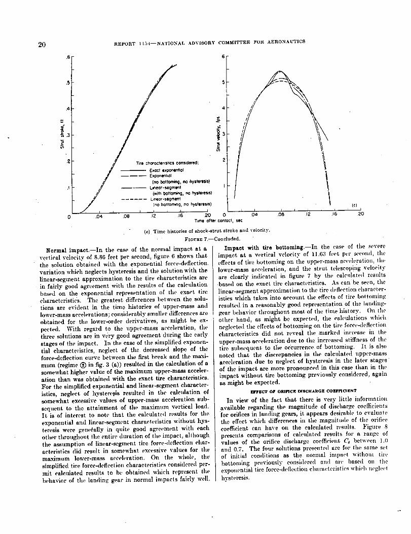
20 REPORT I I54--NATIONAL ADVISORY COMMITTEE FOR AERONAUTICS
.6 6
.5 5
J
.4 4
t_
0, .3 _ 5
o_
.2 . onsidered: 2
- - Exact exponential
#W - - Exponenfiol
,// [no bottominq, no hyste_sis)
.I //# - - Linear-segment I
,// (withbottomi_, no hysteresis)4Y - . L_neor-ssoment
" (no boftominq, no hysteresis}/_ _ i i i i i i i i I
0 .04 .08 .12 .16 20 0Time offer contoct, sec
(e) Time histories of shock-strut stroke and velocity.
FmvRE 7.--Concluded.
Normal impact.--In the case of the normal impact at a
vertical velocity of 8.86 feet per second, figure 6 shows that
the solution obtained with the exponential force-defection,
variation Which neglects hysteresis and the solution with the
linear-segment approximation to the tire characteristics are
in fairly good agreement with the results of the calculation
based on the exponential representation of the exact tire
characteristics. The greatest differences between the solu-
tions are evident in the time histories of upper-mass and
lower-mass accelerations; considerably smaller differences are
obtained for the lower-order derivatives, as might be ex-
pected. With regard to the upper-mass acceleration, the
tlxree solutions are in very good agreement during the early
stages of the impact. In the case of the simplified exponen-tial characteristics, neglect of the decreased slope of the
force-deflection curve between tim first break and the maxi-
mum (regime (_) in fig. 3 (a)) resulted in the calculation of a
somewhat higher value of the maximum upper-mass acceler-ation than was obtained with the exact tire characteristics.
For the simplified exponential and linear-segment character-
istics, neglect of hysteresis resulted in the calculation ofsomewhat excessive values of upper-mass acceleration sub-
sequent to the attainment of the maximum vertical load.
It is of interest to note that the calculated results for tile
exponential and linear-segment characteristics without hys-
teresis were generally in quite good a_eement with each
other throughout the entire duration of the impact, although
the assumption of linear-_gmcnt tire force-deflection char-aeteristics did result in somewhat excessive values for the
maximum lower-mass acceh,ration. On the whole, the
simplified tire force-deflection characteristics considered per-mit ealculated results to be obtained which reprcsent the
behavior of the landing gear in normal impacts fairly well.
(c)I I I J l L _ t I
.04 .08 .I2 J 6 20
Impact with tire bottoming.--In the case of the severe
impact at a vertical velocity of 11.63 feet pot" second, the
effects of tire bottoming on the upper-mass acceleration, thelower-mass acceleration, and the strut telescoping velocity
are clearly indicated in figure 7 by tile calculated results
based on the exact tire characteristics. As can be seen, the
linear-segment approximation to the tire deflection character-istics which takes into account the effects of tire bottoming
resulted in a reasonably good representation of the landing-
gear behavior throughout most of the timehistory. On theother hand, as might be expected, the calculations which
neglected tile effects of bottoming on tile tire force-deflectioncharacteristics did not reveal the marked increase in the
upper-mass acceh;ration due to the increased stiffness of the
tire subsequent, to tlie occurrence of bottoming. It is also
noted that the discrepancies in the calculated upper-mass
acceleration due to neglect of hysteresis in the later stages
of the impact are more pronounced in this case than in theimpact wil_hout tire bottoming previously considered, again
as might be expected.
ErrgCT OF ORI[_C IR DISCHARGE COUFICIENT
In view of the fact that there is very little information
available regarding tile magnitude of discharge coefficientsfor orifices in landing geal_, it appears desirable to evaluatethe effect which differences in the magnitude of the orifice
coefficient can have on the calculate(I results. Figure 8
presents comparisons of calculated results for a range ofvalues of the orifice discharge coefficient C_ between 1.0
and 0.7. The four solutiolLs presented are for the same set
of initial conditions as the normal impact withom tire
bottoming previously considered and are based on the
exponential tire force-deflection characteristics whit.h neglect
hysteresis.

ANALYSIS OF LANDING-GEAR BEHAVIOR 21
-5.0
.._- 2.5
._ -2.02
8
-t.5
-1.0
-.5_....
I i i _ i i I "i[o)
I I I I I I I I t I _ r0 .04 .08 .12 .16 .20 .04 ,08 .12 .t6 .20
Time offer COntOCt, sec
(a) Time histories of upper-mass acceleration arid lower-mass acceleration.
FxavRE 8.--Effect of orifice discharge coefficient on landing-gear behavior; calculations with exponential tire characteristics
without hysteresis. Irr0=8.86 feet per second; n= 1.12.
IO
Uppermass 6
287846---54------4
1.0.9.8
............... °7
-6.04 .08 .12 J6 .20 0 .04 .08 .12
Time offer contocf_ sec
(b) Time histories of landing-gear displacements and velocities.
FxctraE 8.--Continued.
.t6 .20
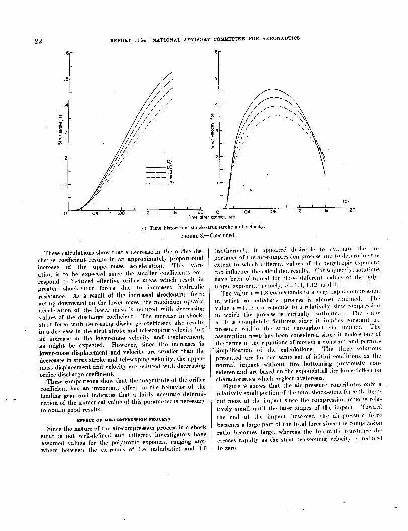
22 REPORT I I54--NATIONAL ADVISORY COMMITTEE FOR AERONAUTICS
.6
.4
2_t
.I
o
L/:" ....'//:?.. "
. /,::...
/..(..." ......... .7.
.04 .08 .L2 .L6
4
#
sf,
I, I J I.20 0
Time alter Contoc/,sec
t.
i ) i r ] I r.04 .08 .12 _6
(c) Time histories of shock-strut stroke and velocity.
FxouaE 8.--Concluded.
(c)
)'0
These calculations show that a decrease in the orifice dis-
charge coefficient results in an approximately proportional
increase it/ the upper-mass acceleration. This vari-
ation is to be expected since the smaller'coefficients cor-
respond to reduced effective orifice areas which result in
greater shock-strut forces due to increased hydraulicresistance. As a result of the increased shock-strut force
acting downward on the lower mass, the maximum upwardacceleration of the lower mass is reduced with decreasing
values of the discharge coefficient. The increase in shock-
strut force with decreasing discharge (_efficient also ,.esults
irt a decrease in the strut stroke and telescoping velocity but "
an increase in the louver-mass velocity and displacement,
as might be expected. However,• since the increases in
lower-mass displacement and velocity are smaller than the
decreases in strut stroke and telescoping velocity, the upper-
mass displacement and velocity are reduced with decreasing
orifice discharge coefficient.
These comparisons show that the magnitude of the orifice
coefficient has an important effect on the behavior of the
landing gear and indicates that a fairly accurate determi-
nation of the numerical value of this paramc(cr is necessaxT
to obtain good results.
_.rr_.cT or Am.com'mEsS,ON Paoc_.ss
Since the nature of the air-compression process in a shock
strut is not well-41efined and different investigatol_ have
assumed values for the polytropic exponent ranging any-
where between the extremes of 1.4 (adiahatic) and 1.0
(isothermal), it apl)eared desirable to evaluate the im-
portance of the air-compression l)ro('ess and to (h, termine tlwextent to which different values of the polytrollie exl)oueut
can influencc the cah'ulated results. Conseql,ently. solutions
have hel',u obtained foi' three (liffcrent vahws of tit(, poly-
tropi(' exponent;namely,, = 1.3, 1.12, and 0.The value :t : 1.3 corresponds to a very rapid ¢'Oml)t'ession
in which an adiabalic process is almost attained. The
vahn' 'tt= 1.12 corrcspon(ls to a relatively slow (.omprcssion
in which the process is virtually isothermal. The value
),=0 is (.ompletely fictitious since it implies constant air
pressure within the strut throughout the impn('t. Tile
assumption n=0 has been consi(lered since it iuakes oue of
the terms in the equations of motion a constant and permits
"simplification of the calculations. The three solutions
presented are for the same set of initial conditions as tilenormal impact without tire bottoming previously con-
sidered and are based on the exponential tire force-deflectioa
characteristics which neglect hysteresis.
Figure 9 shows that the air. prt-ssure contributes only a
relatively small portion of the total shock-strut force tht_ugh-
out most of the iml)act since the compression ratio is rela-
tively small until the later stages of the iml)aet. Toward
the end of the impact, however, the air-pressure for('e
becomes a large part of the total force since the coml)ression
ratio becomes large, whereas the hydraulic resistaa('e tie-
creases rapidly as the strut telescol)iug velocity is reduced
to zero.
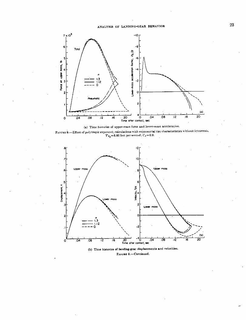
ANALYSIS OF LANDING-GEAR BEHAVIOR 23
7 103
5
4
3
2
\\
I \x
x.,%
I I I I I I I l I I
0 .04 .08 .I 2 .t6 - .20
-IO
-6
#o -6
u,2o
io -2
oEL
_J
I 40
"" ,,\\
i ] J J i I i t t J (°)L
.04 .08 .12 .16 .20
Time ofter contoct_ sec
(a) Time histories of upper-mass force and loweromass acceleration.
FZGVRE 9.--Effect of polytropic exponent; calculations with exponential tire ctlaraeteristics witlmut hysteresis.
Vv0=8.86 feet per secolwl; C_=0.9.
.5
E3
.3
o
I _ 1.12 \,,! .... 0 \
\
I I I.04
,2fIO
.8
6
2
--'\ \ "o .
, , [ , , , ' ' -4_) " _ ' ' ' ' ' . ,..__L__J.08 .t2 .16 .20 ._. .Oe .12 .16 20
T,me oiler Contoc/, sec
(b) Time histories of landing-gear displacements and velocities.
Fmoaz 9.--Continued.

24
.7
.5
-'.4
_.3
.2
REPORT II54--NATIONAL ADVIBORY COMMITTEE FOR AERONAUTICS
I'I
///
/
/ iio J a L J I _ I [ I
•04 .08 .12 .16
2
I (c) J , • j.20 0 .04 .08 .t2 J6 .20
Time offer contoct, sec
As a result, the calculations'show that the magnitude ofthe polytropic exponent has only a very small effect on thebehavior of the landing gear throughout most of the impact.For the practical range of polytropic exponents, variationsin the air-compression process result in only minor differ-ences in landing-gear behavior, even during the very lateststages of the impact. The assumption of constant airpressure in the strut throughout the impact (n=0), however,does lead to the calculation of excessive values of stroke andof the time to reach the maximum stroke. Tile time historyof the shock-strut force calculated on the basis of thisassumption is, on the other hand, in quite good agreementwith the results for the practical range of air-compression
processes.On the whole it appears that the behavior of the lamling
gear is relatively insensitive to variations in tile air-compression process. The foregoing results suggest that, inmany cases, fairly reasonable approximations for the landing-gear force-time variation might be ohtained even if the air-pressure term in the equations of motion were completelyneglected.
SIMPLIFICATION OF EQUATIONS OF MOTION
The preceding studies have indicated that variations in thetire force-deflection characteristics and in tile a!r-comprcssion
process individually have only a relatively minor effect on thecalculated behavior of the landing gear. These results sug-
gest that the equations of motion for the landing gear mightbe simplified by completely neglecting the internal air-
pressure forces in tile shock strut and by conshlering the tireforce-deflection characteristics to be linear. With these as-
sumptions, the equations of motion for the upper mass,lower mass, and complete system (eqs. (16), (17), and (8)) can
(c) Time histories of shock-strut stroke and velocity.
FIouRz 9.--Concluded.
be written as follows for tile case where the wing lift is equalto the weight and the internal friction is neglected:
W_A,__+ A (,_-- i._)_+ It½= 0 ..g
ll'_ 22-- A (il-- i2)_+ az2"+ b -- ll'_= 0g
II'A_,+Tl_ =.,2+az2+b=O£ g
wherek p A, 3
A= _ '2.((_.4,)'_cos_anti
a
(18)
slope of linear approxima(ion to tire force-deflectioncharact,'ristics
b value of force corresponding to zero tire deflection, as
determined from the linear-segment approximation tothe tire force-deflection characteristics
The motion variables at tile beginning of shock-strut de-flection can be readily determined in a manner similar tothat employed in the more general treatment previously dis-cussed. For the simplified equations the variables at the
instant t, are given by11"2
z,=_(1 " IV'`
_ __ / _ ,_a,_"--31 ¢'° ll" z'2
agIn most cases the term _ z, 2 is small in comparison with ioz
so that i,_ io.

ANALYSIS OF LANDING-GEAR BEHAVIOR _D
-3.0
-2.5
-2.0
8o
'-1.5
i_, - t.C
-IO
-8
g
.2j
o!1 $_ut,onof fiqure4// S,m_!!_,d_s!,m,w_,==3,.,
Simplified system W2 0
, L i I _ I I I I J.04 .08 .t Z .t6 .20
\
0 .04 .08 .t 2 .t
(o)
.2'o
Time after contact, sec
(a) Time histories of upper-mass acceleration and lower-mass acceleration.
FZGURv. 10.--Evaluation of calculated results for simplified systems. VVo=8.86 feet per second; C_----O.9.
The values determined from equations (19) are used as
initial conditions in the solution of equations (18).
The fact that the lower mass is a relatively small fraction of
the total mass suggests that the system might be simplified
even further without greatly modifying the calculated results
by assuming the lower mass to be equal to zero. With this
assumption t,=0 and the initial values of the variables in
equations (18) correspond to the conditions at initial contact.
EVALUATION OF SIMPLIFICATION
In order to evaluate the applicability of these simplifica-
tions, the behavior of the landing gear has been calculated in
accordance with equations (18) for an impact with an initial
vertical velocity of 8.86 feet per second. A similar calcula-
tion has been made with the assumption Wr------0. These
results are compared in figure 10 with the more exact solu-
tions previously presented in figure 4, which include con-
sideration of the air-compression springing and the exact
exponential tire characteristics. A time history of the lower-
mass acceleration is not presented for the case where 14_ is
assumed equal to zero since the values of _/g have no
significance in this case.
Figure 10 shows that the two simplified solutions are in
quite good agreement with each other, as might be expected,
and are also in fairly good agreement with the more exact
results. Neglecting the air-pressure forces and assuming alinear tire force-deflection variation resulted in the calcula-
tion of slightly lower "values for the maximum upper-mass
acceleration and somewhat higher values for the maximum
stroke than were obtained with the more exact equations.
The effect of neglecting tim lower mass was primarily to
reduce the lower-mass displacement (tire deflection), as a
result of the elimination of the lower=mass inertia reaction.
On the whole, it appears that the assumptions considered
permit appreciable simplification of the'equations o.f motion
without greatly impairing the validity of the calculated results.
GENERALIZED TREATMENT
Equations and solutions.--By writing the simplified equa-
tions of motion in terms of dimensionless variables, general-
ized solutions can be obtained for a wide range of landing-gear
and impact parameters which may be useful in pre-
liminary design. If _l_ is taken equal to zero and it isfurther assumed that the tire force-deflection curve is
represented by a single straight line through the origin
(b=0 throughout the impact), equations (18) reduce to
W_j _t+A(_,__2)2=0 I
g
A(zt-- _:)_--az== 0
W__j_t+az==0g
(20)
where Wt,A, and a are constants, as previously defined, andg
any two of the foregoing equations are sufficient to describe
completelythebehaviorof thesystem. With this representa-
tion of the system, the shock strut begins to deflect at the in-
stant of initial contact (t,=0). Thus, the initial conditions
for equations (20) are the initial impact conditions; namely,
zao= Z2o= 0 and #,to= k2o= _,o.

26
o.
.6
,5
.4
.j..
.2
.I
c5
.3
REPORT i I7_4--NATIONAL ADVISORY COMMITTEE FOR AERONAUTICS
,r,
oa
Sotut_onof fiqure 4--_ Simp4ifiedsystem, W2 = 131 Ib.... Sim_J_ed system, f,_ -"0
6s ,2 ,6 ' so
8
6
Lo*e*_o. \ N
- 4L _ I l i I I I 1o ,04 .08 .12 .16
T,me after contact,sec
(b) Tinlc hi_turit-+ of landillg-gc, ar +li_placemc]_l_+ aml vcLucilit,_.
]'_IG UII E lO.--Cont, inued.
(b)I I
20
//7 5 ¸
// ,,!/ \
-,,7/-j/
/// - - S_ml_fied SySfem, W2 : I_I Ib
.04 .08 .12 .16 .20 0 04 .08 .12 .16Time offer confoct,se¢
(c) Time historics of shock-strut _trukc and velocity.
]"t6ua_ lO.--CoHcluded.
(c}f ?

ANALYSIS OF LANDINCr-GEAR BEHAVIOR
As can be seen, with tile equations in this form, tile solution
Wt,
depends on five parametel_, namely, _- A, a, and the
initial conditions io and zo. However, since Zo=0 in allcases, the number of variable parameters is reduced to four.In view of the fact that these parameters are independent ofone another and each may take on a large range of values, a
great many solutions and a large number of graphs wot,hl berequired to cover the entire range of landing-gear and impactparameters with the equations in tile form of equations (20).
The number of independent parameters which have to beconsidered may be greatly decreased by the introduction ofgeneralized dimensionless variables and the correspondingtransformations of equations (20). In this case, generalizedvariables can be obtained'which permit transformation of the
equations of motion to a form which does not involve anyconstants. With the equations in this form, there is onlyone variable parameter, namely, the initial velocity param-eter. To determine the generalized variables which satisfythe afdrementioned requirements, let
and
Thus,
and
U-_-ZOt
O=tB
,, du' .. a
Substituting these new variables permits equations (20)to be written as
(u,'-- uT)2+(A _) u,"= 0"
,,, [ a/_'_
The number of independent parameters _-ill be redi,cedif all the combined constants in equations (20a) are set
equal to one another, that is, let
a Il5 a . a/_'A g =--A _=_7_
From this relationship, it can be seen that
A"_=W,/g
and
Thus the generalized wu'iables become
u,=z, A u.,=z,, g._
"' = ,_ =" %, _._ ":' =,re =: W _,tg
and
where
27
t# d2_ti -
t a
With these uew varhtbles equal,oils (20) can lie written lis -'
(ul'--u:')2+u#=O)
(ui,_u2,)2_u2=O _ (21tu#+u_.=0 )
where any two of tkese equations are sufficient to describethe behavior of the system.
Inasmuch as equations (21) do not. involve any constants.their solutions are completely determined by the initial val-ues of the variables. Since the displacements at initial
contact u_o and u.% are equal to zero and the initial velocitiesu, o' and u2o' are equal, the only parameter is the initialdimensionless velocity
/ A:gUo'= io _l T-C_,a
where uo'----uzo'=u2o '.Generalized solutions of equations (21) are presented in
figure 11 for values of u_' corresponding to a wide range oflanding-gear and impact parumeters. Parts (a_ to (e) offigure 11 show the variations of the dimensionless variablesduring the impact; parts (f) and (g) show the maximumvalues of the more important variables as functions of 'u0'.Part (h) shows the shock-strut effectiveness _/, and thelanding-gear effectiveness _zt. The shock-strut effective-ness, sometimes called "efficiency" and, in Europe, "plan,-metric ratio," is defined as
f0 qmasq._lH do-
_i$" #p
_1 mat O'm_z'
where ¢=u,--u_ is the dimensionless shock-strut stroke.Since ,. represents the ratio of the energy actually" absorbed
by the shock strut to the maximum energy which the strutcould possibly absorb for any combination of maximumacceleration (or load) and maximum stroke, it serves as ameasure of the extent to which a given combination ofmaximum load and stroke has been utilized to absorb the
energy of an impact. A similar measure of the energyabsorption effectiveness of the landing gear as a whole isgiven by ,ns which is defined by
fO lllmil_ 1i1 #t dui
lilt _ _, ,# _,lii lliaX l/_|m¢.l_
' Eqilation.t (71) may I_, II.ducl,d to a shllk" cqu_ti.n hi OlW variable by dillei'enllating llw
Ili_l t*qll;lliOll lilld subMilulllig lot ii._" Ill Ihe nr$1Cqll:illoll. This gil-p._ (tll'-I-lll'"jI'4"llltttll.
]ly illlrt_lllt'hll fill' II_*w Vlll'tllllk' tlll#l', Ihi.< i,qllllli_lll lll_iy I_ I_cdlltl._l Ill lhl' _,(_lli,l-
ol-ilt_r iqlll:lltoll (tt:Ji- ir")i-t-//"_lll ._lihi_'t'l t', Ihe hlilkil Clillllil iiill._ ii_= its' :lilll u _'-II.

28 REPORT l l_4--NATIONAL ADVISORY COMMITTEE FOR AERONAUTICS
loJ=
=
10
8
c
_6
4
(3
2
I
,.2 ,.6 2.0 2.4 2.8
Ocmc_ulss lime, @
(a) Relatiozlship between upper-mass acceleration, [ower-ms._s displacement, and time.
FI(}URE ll.--Generalized solutions for simplified system.
2 16 20 2.4 2,8Dimensionless time, 0
(b) I(elationship between uppcr-ma_s displacemeltt and time.
FIOURE l 1.--Continued.
32 36

ANALYSIS OF LANDING-GEAR BEHAVIOR 9.9
The generalized results presented in figure 11 a can be
used to estimate the performance of a given landing gear of
kno_,_n configuration for particular impact conditions or to
choose the dimensions for a landing gear when the impactconditions and desired performance are specified.
Applicability of solutions.--To ilhlstrate the applicabilityof the generalized solutions, tile curves of figure 11 have
been applied to the previously considered case of the normalimpact at an initial vertical velocity of 8.86 feet per second
for comparison with thc more exact solution presented infigure 4. In order to make use of the generalized solutions
Although time.history Imlutions are presented for values of u,' as Imall as 0.5, It will be
noted that valuesof utm.,. Gram.I.. and _,. arenot givenforvaluesofue'<_l.& It can beI_enfromthetimehistoriestLatthecharacteristicsofthesolutionInthelaterst_es oftileim-pact ebonizeas u,' becorm,s small;In pttrtleuiar,u, increasesandthecurve of _la41 _ a fUl]_
tlon o[ u.' appearsto react,a minimumat somevalue of ue'_l.& Furthermo_,the laterstages of the solutions great|y stretch out in time and appear to be almost asymptotic ill
character. Several different artalytlcal, numerical, and analogue methods were applied in an
attempt to study this l)ha_ of the problem further but tbeextremely slow mac of chaugc of
the variables in this n, gion prcven_d suc.cesstul completion of the solutions.
287846----54 --1
it is first necessary to approximate the tire force-deflectioncharacteristics"by a simple linear variation. Two such
linear approximations which might be considered suitable
for this purpose are shown in figure 12. • Linear approxi-
mation I is a straight line through the origin having a slope
a-----18.5X10 a pounds per foot (a'=ad=41.6XlO _ lb). This
value of a and the other pertinent landing-gear, and impactparameters result in a value of the initial dimensionless
velocity parameter u0'-----2.57. Linear. approximation II is
a straight line with slope a---21.3)<103 pounds per foot
•(a'-----47.9)<10 a lb) which does not pass through the originbut intersects the displacement axis at a vahle of
Z2(rv .0)=0.0508 foot. With this value of a, uo'=2.39.
Since the solutions of figure 11 have been calculated only
for integral values of u0', curves for tile foregoing values of
uo' were graphically interpolated by cross plotting. These
results were then converted to dimensional vahles by multi-

30 REPORT I154--NATIONAL ADV1SORY COMMITTEE FOR AERONAUTICS
plying tile dimensionless variables by Hw apl)ropriate
constants. Tile results obtained are compared in figure 13
with tile more exact solution presented in figure 4. Tile
values based on linear approximation I have been plotted
exactly as determined from the generalized solutions. Theresults for linear approximation II, however, have been
displaced relative to the origin o.f coordinates as indicated
• in the following discussion.The assumption of linear approximation II implies that
the system must move a distance equal to z_(r%.o) after
initial contact (at constant velocity since the whig lift is
take n equal to the weight) before any finite ground reaction
can develop. The derivation of the equations of motion,on the other hand, assumes that the ground reaction in-
creases linearly with deflection from tlw instant of initialcontact. As a result, the equations of motion (1o not apply
until after the systcm has attained a displacement equal to
z=(rv.o) , which occurs at a time after initial contact
t= z_(Pv*'°_. In other words, the equations of motionVv o
apply to a coordinate system t,'ansformed so that the tire
force.41eflection relationship passes through the origin; that
is, a coordinate system ,lisplaced by z:(_v=.o ) relative to
8 9
tlw coordinate system originating at the point of initial
contact. It therefore follows that the i,ppcr-ntass and
lower-mass displacements determine, I from the genet'alizedsolutions for the case of linear approximation Ii lllltSt b*'
increased by a constant amount equal to -_(rv =0)' in this
case 0.0508 foot. anti all rt.sults must I,e displa,'ed in
time I,3" a constant increment At-= I'vo , in this case
0'050--8--0.0057 second, relative to the instant of initial8.86
contact. These corrections have been incorporated in plot-
ting the curves for linear approximation II shown in figure 13.As can be seen, the results ol,taincd t)y appli,'ation of the
generalized solutions, particularly 1,3" the metho,I cmlflOying
linear applx)ximation II, arc in fairl._" good agreement with thq,
more exact solution. Thc discrel)ancies which exist art,
attributable to the neglect of the shock-strut preloading and
springing provided by the air-pressure forcc, ncglect of thelower mass, and to ,liffereuccs ])ctwccll the ver's. simple tit','force_lcflection relationshil,s assume,I and the exact tire
characteristics. On the whoh', it appeat.'s that the general-izcd results offer a means for rapidly est imat ing the behavior
of the landing gear within rcasonalth' limits of accuracy and
may thc,'cfore I,c useful for preliminary desiglt I)urposes.

ANALYSISOFLANDING-GEAR BEHAVIOR " 31
-6
J
_5
0 I 8 9 io
SUMMARY OF RESULTS AND CONCLUSIONS
A theoretical study has been math _ of the behavior of the
conventional type of oleo-pneumatic landing gear during the
process of landing impact. The basic analysis is presented
in a general form and treats the motions of the landing gear
prior to and subsequent to the beginning of shock-strut
deflection. .In the flint phase of the impact the landing gear
is treated as a single-degree-of-freedom system in order todetermine the conditions of motion at the instant of initial
shock-strut deflection, after which instant the landing gear is
considered as a system with two degrees of freedom. The
. equations for the two-degree-of-free(lom system consider
such factom as the hydraulic (velocity square) resistance of
the orifice, the forces due to air compression and internal
friction in the shock strut, the nonlinear force-deflectioncharacteristics of the tire, the wing lift, the inclination of the
landing gear, aud the effects of wheel spin-up drag loads.
The applicability of the analysis to actual landing geam
has been investigated for the particular case of a vertical
landing gear in the absence of drag loads by comparing
calculated results with expex'imental drop-test data for corre-
sponding impact comlitions, fox" both a normal iml)aet aml a
severe impa('t involving tire bottoming.
Studies have also I)een made to determine th(' effc('ts of
variations in st,ch parameters as the dynamic force-deflection
chara(.tcristivs df the tit'c, tit,' ot'ifi(.e dis_'hargc _.,)cfl_('ieltt. and
the effective polytropic exponent for the air-coral)Cession
process, which might not be known accurately i,l practical
design problems.In addition to the more exact treatment an investigation
has also been made to determine the exteut to which the
haste equations of motion can lie simplified and still yielduseful results. Generalized solutions of the simplitied
equations obtained arc presented for a wide range of landing-
gear and impact paramett:l_.On the basis of the foregoing studies the following con-
clusions are indicated:
I. The hehavior of the landing gea,' us ('ah'ulated from the
basic equations of motion was found to 1)e ingood agrecInent
with experimental th_op-tcst data fox' the case of a vertical
landing gear in the absence of drag lottds, for both a normal
impact anti a severe impact involving tire I)ot toming.
2. A study of the effects of variations in the for(.e-deflct't ioit
characteristics of the tire imlicalcs that
a. In the case of a nornml iml)act without tire I)ottoming,
reasonable variatious in the force-deih,('tion (.haracteristius
of the tire have only a relatively small eire/'l on the calculated
l)ehavior of the ]tXtVllillg gear. Approxinutting t!:: :.t!a,-
eonll)licaled forco-defh,('tion characteristit's of the uvttm] tit,
I)y simplified expolwntial or linoar-scgmcnt vnrialions appq,_trs

32 REPORT l154--NATIONAL ADVISORY COMMITTEE FOR AERONAUTICS
1.6
A
t_
-_ 1.2E
E
o
!
•._ :4
=
(f) VariAtion of maximum upper-ma_ acceleration and timeto reach maxinmm upper-mas._ acceleration with initial ve ocity parame_.r.
FIGURE 11.--Continued.
to be adequate for practical purposes. Tire hysteresis wasfound to be relatively unimportant.
b. In the case of a severe impact involving tire bottoming,the use of simplified exponential and linear-segment approxi-mations to the actual tire force-deflection characteristicswhich neglect the effects of tire bottoming, although adequate
up to the instant of bottoming, fails to indicate the pro-nounced increase in landing-gear load which results from
bottoming of the tire. The use of exponential or linear-segment approximations to the tire characteristics whichtake into account the increased stiffness of the tire that re-suits from bottoming, however, yields good results.
3. A study of the importance of the discharge coefficientof the orifice indicates that the magnitude of the dischargecoefficient has a marked effect on the calculated behavior of
the landing gear; a decrease in the discharge coefficient (orthe product of the discharge coefficient and the net orificearea) results in an approximately proportional increase inthe maximum upper-mass acceleration.
4. A study of the importance of the air-comprt._ion processin the shock strut indicates that the air springing is of only
minor significance :lu.oughout most of the imp,ct, and thatvariations in the effective polytropic exponent, between theisothermal r_.lue of 1.0 and the near*adiabatic value of 1.3
ha;_ onJy a secondary effect on the calculated behavior of
the landing gear. Even the assumption of constant airpressure in the strut equal to the initial-pressure (n=0)yields fairly good results, which may be adequate for manypractical purposes.
5. An investigation of the extent to which the equations ofmotion for the landing gear can be simplified and still yield
acceptable calculated results indicates that:, for many prac-tical purposes,, the air-pressure force in the shock strut canbe completely neglected, the tire force-deflection relationshipcan be assumed to be linear, and the lower or unsprung mass
can be taken equal to zero.6. Generalization of the equations of motion for the
simplified system described in the preceding paragraphshows that the behavior of tiffs system is completely deter-mined by the magnitude of one parameter, namely, thedimensionless initial-velocity parameter. Solution of these
generalized equations in terms of dimensionless variablespermits compact representation of the behavior of the systemfor a wide range of landing-gear and impact parameters,which may be useftd for rapidly estimating landing:gear
performance in preliminary design.
LANGLEY AERONAUTICAL LABORATORY,
NATIONAL ADVISORY COMMITTEE FOR AEItONAUTICS_
LANGLEY FIELD, VA., :_'ay 1, 1952.
0 0 I 2 3 4 5 6Inifiol climens4onleSsvelocity, _/0'

ANALYSIS OF LANDING-_EAR BEHAVIOR 33
l0
i I
_-50
_, 4or,
3o
2o
io
i I1i 2 3 4 5
Inihol dimensionless velocity, u O'
6 7 u
(h) Variul iotl ,)f H_ock-..trul elfuct iv(_n('_, and landillg-Kear effecli','en(,s_ with inil ial vH_wily im.ramet,'r.
]"Xr;I",_E 11.--('_)=wludc(1.

34 REPORT l I54--NATIONAL "ADVISORY COMMITTEE FOR AERONAUTICS
/
/
5 //
//
Lineor opproximotion I:-. // ""- Experimental:
ff=lS.SXlO 3 Ib/fl "Y VVo =8.86 fp$/
//
//
//
//
//
//
//
//
//
!/
//
I
opproximotio*_ TJr:
O = 21.3X 10³ Ib/fl
I I J I
0 _ .t .2 2, ,4 ..5Tire deflection, z2, ft
FIGURE 12.--Linear approximations to tire force-deflection character-
istjes u_d ill application of ge.eralized solutions.
%
%\
\
_Solution of figure 4
Generolized solutions
.... u o' • 2.57 .(o.. 18.5x10³)
-- -- u O' • 2.39 (o • 21.3x I02_)

ANALYSIS OF LANDING-GEAR BEHAVIOR 30
UoPer mass
/
/
.04
Lower moSS
%
SolutiOn of figure 4Generalized solutions
uo' = 2.57 (o = 18.5 x I03)
uo' -" 2.39 (O = 21.3 x 10³}
6
o
2F10
\
2
0 Lower moss "_ _
-2
'1_ .2,_ -4 _ _ =J 0 .0'4 .08 J2 .16i08 ,12
Time offer contacts sec
(b) Time histories.or landing-gear disl)laceme_Lts and velocities.
Fic, raz 13._Continued.
(1_)
.20
#
\
0 .04 .08
Solut,on of fK_'re 4
Generolized solutions
uo' : 2.57 [o : 18.5 x IO s)
v o' = 2.39 (o = 21.3 x 10³)
.12 .16 .20 0 .04
Time after confoct, sec
(c) Time histories of shock-strut stroke and velocity.
FmVaF, 13.--Concluded.
.08
(c)
,12 J6 .20

APPENDIX A
NUMERICAL INTEGRATION PROCEDURES
As previously noted, most of tile specific solutions presentedin this report were obtained with a numerical integration
procedure, termed tile "linear procedure," which assumes
changes in the variables to be linear over fiifite time intervals.
With this procedure a time interval t=0.001 second was
used in order to obtain the desired accuracy for the particular
cases considered. A few of the specific solutions presented
were obtained by means of a procedure, termed the "quad-
ratic procedure," which assumes a quadratic variation of
displacement with time for successive intervals. This pro-
cedure, although requiring somewhat more computing time
per interval, may permit an increase in the interval size for
a given accuracy, in some cases allowing a reduction in the
total computing time required. In the case of the more
exact equations of nmtion the accuracy of the (ttmdratic pro-cedure with a time interval of 0.002 second appears to be
equal to that of the linear procedure with an interval of0.001 second. Although the accuracy uaiurally decreases
with increasing interval size, the loss in accuracy for pro-
portionate increases in interval size appears to be smaller for
the quadratic than for the lim, ar procedure. In the case of
the simplified equations of motion reasonably satis:actory
results were obtained in.test coml)utations with the quadratic
procedure for intervals as large as 0.01 second, whereas the
linear procedure was considered questiomd_h' for intervals
larger than 0.002 secoud.
The generalized soh'tions prest, nted, be<.ause of the
1'elntively simple form of the equations of motion, wereobtained with the well-known Runge-Kutta l)rocedure.
A study of the allowable interval size rcsuhcd in the vse of
an interval A0=0.0S, which cor,'esl)onds to a time interval of
about 0.005 second for the landing gear undt, t' eonside,'a!ion.
LINEAR PROCEDURE
In this step-by-step procedure the variations in dis'
placement, velocity, anti acceleration are assumed to belinear over each finite time interval _. The metho(I, as
used, involves one stag(' of iteration. Linear oxtrapohdion
of the velocity at the end of any interval is used to obtain
estimated values of velocity and displacement for the next
interval. These values at'(, then used to eah'ulate vahu.'s of
the acceleration in aecordanee with the equalions of motion.
Integration of tlw acceleration provides improved values of
the velocity aml, if desired, the disl)laeement and accelera-
tion. In this procedure all integrations are performc_[ by
al)l)licalion of the trapezoidal rule.
The following derivation illustrates the application of the
linear procedure to the equations of motion for the landing
gear, which apply subsequenl to the beghming of shock-s!rut
deflection at ti,ne t,. In the examl)le ])resented internal
friction forces are negh,eted in order to simplify the deriva-
36
tion. However. lhe same general [)t'ocedtlre <'an l)t, ust'<l if
these, or other rompli('ating effects, are in<.h.h'd in tlie
et[ua t ions.For the <'ase under consideration the etltmtions of moti+m
(,,(I s. (16). (17). aml (S)) can be written +is follows:
IV_ : , A(=t_i,).,.+B[I_C(z,_z:)]-,,D=O (All.¢- 1 -'7" - ' 'g
1I': 2_--d(it-- i-,)2--B[1 -C(z,--z.:)l-"+F,.,(zz)- II'z= 0-7-
(A2)
II'1 W+-- 2,+--: "-:, _ Fv ,( z,)= E=O IA3)g g " .
_A'hel'e
;+ O .-t,?
+4=_ ._,T+_:f,,)_,._+-b
B = p,,+,A,,<'os¢
c=-++t'o COS¢
D=KLII'-W,
E= II'(KL-- 1)
Solving equation (A:_) for -i gives
_=[F_G2._HFv,(z:)] 1g(A4)
xvhel'P
F= 11:(1- K_:,_II'l
Integrating eqt,atiotl (A4) with resl)et't to t b<,tweelt the
limits l, and I and noting that ._l :i:,=- -z, gives
il-_ ;-,-}- l"r--G(k.2-- :">-"ji"<A5)
where r= (t--t,).
Integrating again and holing lhat z_=z,=z, giv_,-_
Zl----(I+(;)(Z,T-,r)+ "2 -- z,.-- l"t (::)dr ,Ir
CA6)

ANALYSIS OF LANDING-GEAR BEHAVIOR
Substituting for -;l alu[ zt in equation (A2) gives
_., l (A[(l+G)(L_i,)+Fr_llf[F,. (z..,)dr]"÷
B{ 1--C [(1-t-G) (z,-£ 2,r--z.,.)+ F[='_,I2 J,+r"dor"1",-+ (=_)d r dr]l-"--Fv,(z->.)--'l':')
Tilt, nmtion of till' landing gear subsequent to tilt, Iwginning
of shock-strut deflection is deternlined by means of a sit, p-
by-step solution of equalion (AT). This nltnlerical procedureviehls time histories, of the lowei'-nmss motion variables
.,._, i+, and _2. from which the motion variabh, s for the upper
mass 2t. it, and zt. can be calculated by nlelins of equations
(A4L (A5), and (A6).The initial conditions for the step-lu,step procedure are
21_'0=Z2_'0= Zv I
• :- - " (AS)Zln.o= _2n .0-- Zr
" 2 --2
_" Lit m0= _ 2it o0 -';r
where z,. -,. and 5, are the conditionls of inotion at the
beginning of shock-strut delteetion as deternfined froth the
solution for the Olw-degree-of-freedom systeni.
Estimated vnhies of tilt' lower-niass velocity lit the end of
the first tilne increnlent _ following the ]leginning of shock-
strut de_,ction can lw obtained from the expression
i* i=i,+tZ, tag)2n.
or. as a ill'st approxilnation,
2_.1 Z,
The corl'eSllonding dispial.enloli! is girt'IX ILV
z,.,.l=z,+ 2 (_21+ i,) (AIO)
Afte( till, iuitial conditions and the conditions at tho end
of the first time illvrenloltt al't' establisilt'd, a siep-lu-stel/
• calculation ofthe motion can bt, obtained by i'mitine opera-
tions as indicated by the following general lU'OCedurl' whMi
applies at any. time r=tlt after the beginning of till' process.
The operatimls indicated are based on integration by appli-
cation of the trapezoidal ruh':
it* --Zz._l+(Z'-.-i--;'2, ")=Zz,,-:a+_(22" -l+_''--_) (All)2it-- --. .
• . , :* t+t'zz,,-t t2zL=z.,.._,+)-(z+.._ t r,_,)=z:._ +_- (,_.-t+;%-+:)
OU2)
With the estilnatvd vah,'s =* tuld -* tilt, accch, ration of,a:_ n +=2 n
tlw ]owvr mass cmi Iw deterlnim,d fry sul_sliti,tion ill the
37
A7b
al>pL.opl.iate integrodiffvrt,ntial _,quatiou For thc _v.t,,nl
equatiori (A7) in the l)l'Vsl'nl case. Thus
-2 =.f(i.*., . z*_, . r,,) IAI:_:
In equation (A7) tilt, itm,gral exprt,ssions vtin also I_,+ t,vtlht-
ated by application of tilt, Irapvz,fidal rule. Fnr vxanxl>h'
when Ft,+ (_2) = ,'l z.,',
Y0 _ O ~ r r"ez,,dr_(z , + -- ").. --2./1
_ -- --~: ..... 't-I
(' (,+-I 1+ _ , .\14
__. | z2',lr+_(z:,,_i--Z:,,')J 0 . t. -
tllld
L"J"'0• L+....' L....z,'dr ,lr_ z/dr,It+
(r<,,+, j.,,,. -- - "d I A l.',Z .rd'r
An ilnl)l'OVi'd vtlhw for tilt, vt,hwity is ,+l>tai,,ed ft'iml th,
t,xpression
• --_ + ._ (._ :,_ i .-- _ 2,, ) (._k I I;Z2 n -- ~2n_ t
Tilis vahie is IlSt,tl ill thl" vl/IcillaliOll <{[" IIW t,+tililttll,d vi,hl,'il '
"*.+i lind di.e, pltit'onn'lil :'*.+l fol' llil + iwxl hilervtll_
If dl,sil'ed, iniprovtql '+,-lihlos of tht, disl>hi<'elnt'nl till<
adceloration'for iho nih intt,i'va[ +uli-,tqlUeiit to thl, Iw,.zhinin:
of shovk-+ti'ui ih,lh,viiml (,till lit + ohlllilu,tl Ill fldlw,;+:
_ _~ 2f_ + ,+2,,---2,,_t :_ (=:.,,,_ _,_7:,,)
=z2,,_t++__,,,_,+]. (_:,2,--_.,) tat,
and_2 =.1(-2 . 2.',. "i',,) (At:"
whPl'e.f(k,.,,, z.>,,, rn ) iS lilt IIp[ll'Opriiitt' eqlllltiOli ft,r tht, systt'll
guvh its oqulilioli (AT).
lYitii tilt' vallle._ of :2., +_.,,,, hnd -2,,, tht, niotion vilrilltlh,s t'_,
l|il' uppt,r Inas,_ ._t,,, ._l,,. tilid ,i,, ('till lit' Vjlll'lihilt'd'st'lllirlill'l
• fronl eqillltiOllS (A4), (AS), litld (All), its prl,viousiy lloh,<l.
In selling tip till' niiniel'it'iil l)rovedill't_ nst'll ill ohlliiniitlz th
solutions |)ro:si,lllod in lifts I'l'i)ol'l, lilt 4,,¢llhltlliOll id' Ihe t,rl'(U
introduced lly the llrovi'thll't ' indiclllt'd Iluil h wouhl llOl I,
li<,<.ossilr 3. to <.lll<.ilitlto lilt' inllil'OXt'd Xllhlt,S of Ilw tlisllltlt',
nlelit ,_'2,+ (ell. (it 17) ) tit' tilt' IlC<'t,ltq'lilion ]2. (C<l. ( -ti 1,_ ) ). [ hlxt
t,Vl,l', inlproved vilhlt'._ of lho vt,hiciiy :.% wt,rt, <,ah,ullilt,ll 1>

38 REPORT 1154--NATIONAL ADVISORY
means of equation (A16] for tile purpose of determiningestimated values of tile velocity i2 and the displacement z:
(eqs. (All) and (AI2)) fox" tilt, in('rcmeI)t immediately
following.In order to ilhlstrate the application of the method, a
tabular computing prot.edm'e for the solution of the system
represented by equations (A1), (A2). and (A3) is presented in
table I.OUADRAT1C plgocED UR Z
In this step-by-step procedure a quadratic variation of
displacement is assumed over su(.eossive equal finite timeintervals for the purpose of extrapolating values of the
COMMITTEE FOR AERONAUTICS
motion variables from one interval to the next. With this
assumption the displacement variation over two successive
equal time intervals is completely determined by the threevalues of (lisplaccmeIU at the beginning and end of each of
tile two intervals. By writing the quadratic variation ill
difference fro'm, the velocity anti ac(.eleration at tilt, midpoitlt
of the double iuterval can be expressed in tcrnls of the Ihvcc
displacement values previously mcntiomql. Substit u ting for
the velocity and acceleration in the differential equal ions for
tile system yields difference equations of motion ill tortus (if
successive displacenient values which can 1)o evahmtcd
interval by interval.
TABLE I
LINEAR PROCEDURE
Row Quantit.v
'r
E(luation
_:._,+_(z:._i+ :._,)
Proeed.ure t
............................
C . ..
'0 ,;. z....+ _ (z:.__ ÷ z:.)_+_®_
@ F,,_(z',) ....................
,._ fo%,(z'.) dr l':qual ion(A 14)
®22 m
@
@
l.'quat iott (.._ 15)
l:;q uat ion (AT)
_:.-,+_ (e:.-_ + e:.)
I . .°
_('-...+_ .... )
..•7..,R41
o
Zl m
21 m
i ' C:.+_ (_.-, + _.)
l.:qualioli (A4)
EquatioH (AS)
l,:qual ion (Aft)
D,qerinined from tire fort'v-
deflection eharacteri-tic,_.
E r.
®,+_ l_+_,l
. _
Given by equal ion (A7).
2 _
!®+_ [® + ®,,lg
i
......... + ..........
(liv('H hy t,(i}lali,m (A43.
(fix'I'll I)y (qltlltlhnl (AS).
(,ivvil I>y _.qualillti (._.6_.
O'p dl'lllilt"_ vftlll(' fi)r liri'vi-u_ liliie inli,rvah

ANALYSIS OF LANDING-GEAR BEHAVIOR
Tile following derivation shows how tile procedure can be
applied to the determination of tlle behavior of the landing
gear subsequent to the beginning of shock-strut deflection at
time t,. In order to simplify the derivation, internal friction
forces are again neglected in setting-up the equations of
motion.
The assumption of a quadratic variation of displacement
with time (constant acceleration) over two successive inter-
vals, each of duration t, permits expressing the velocity and
acceleration at the midpoints of the double interval (see
sketch) in terms of tile displacement Values at the beginning,
midpoint, and end of the double interval by the equations
(see ref. 5, p. 16):
• • =z,,+l.z.-i (A19)Z_ 2e
and
Z_+l-- 2Zn-_-Z__lz-= _2 (A20)
/i
zt z_+,
0 • ' 2,E (n-I)_ _ [n÷l),_r.t-tr
39
"where
,_.+1= 2TI:,_,- w..=_._1-g,'[F,, (=_.)+ E]
8,,+1= 2IV_z2,,+(11"1. lI':)z2,,_i÷ 211'1(zl,,- z,,,_,)_g,2[ Fv•(Z2.)+ El
£tlld
4 1I'12_2V.+,=---_- {Bil--C( z, -- z...)I-" + D}
Equations (tt22) and (A23) are essentially extrapolation fornmlas which l)ernfit the (Icterminalion of values for the
upper-mass and lower-mass displacements to come from the values of displacement alr_,ady cah'ulated. 'i'hes(, (,qualioIls
tiros permit step-by-step calculation of the displa('enwnts as the iml)a('t llrogresses, starting with the initial comlitiot_s.
from which tile t,ppcr-mass and lower-mass velocities and acceh, r'ltions can t)e dctcrmincd by means _,f C¢lUalioas (At9)
and (A20).
Since the caletdation of the displacenwnts zt and z2 at any instant by m('alls of eqvations (A22) aml (A23) requires
vahws for the displacements at two previous instants, the routiuo al)plicatioa of these equations can tlcgfit only a! Iheend of the second interval (r=2t) following tile beginning of shock-st,'ut dclh'ction. Befi)rc the disl)la('t,nwnts at th[' eml
of the second interval can be calculated, however, it is nccessat T to dctermint, the disl)lacements :it lhe eml of the first
interval. These vahtcs (.an be obtained from the conditions of motion at lhc inslanl of initial sh(.'l<-s/rul dt,lh,cliotl by
apl)lying equations (A19) and (A20) to the instant t=t..
where .;., _.., and z. are the velocity, acceleration, and displacement at tile end of the nth interval (r=._) after lhe
beginning of shock-strut deformation and z.-t and z.+t are tile displacements at the end of intervals n--1 aml i,'l.
respect iv ely.
Substituting the difference relations for _, i_, 21, and :22 into equations (A1) and (A3) permits _riti.g the equatioli..,
of motion for the landing gear in difference form as follows:
IVI A (A21)-_-i_(z1.+,-- 2z, .+ z,._l)+_72(z,.+,--z,._l--z:.+l + z:._O'-i-.B[1--C(zl.-- z_..)]-" ÷ D=0
and
z1,,+1 = 2zl.-- zl._ 1-- a(z-_.+t-- 2 z...-k- z._ 1)--So"[ Fv,(z2.) + El (A22)
where the constants are as (iefi_le(1 in the previous section.
Substituting for zt,_+t ill equation (A21) gives

40
At tile instant of initial shock-strut deflection
.<-In.o-- Z2_.O -'_r
Application of tile difference eqtlatiolls (._t19) and (A20)to tile instant t=t, (that is, n=0) gives the following
equations:
!Zn.l--Zn.--1
Z'=- 2e (.-k2 5)
z __ Z "" t _ 2 7"-'"1- 'Z"" - I-(
Since tile landing gear is considered as a one-degree-of-
freedom system front initial contact up to tile instant t=t,,
TABLE II
QUADRATIC PROCEDURI-:
REPORT I154--NATIONAL ADVISORY COMMITTEE FOR AERONAUTICS
tile foregoing applieation of tile dilferenee equati¢ms t.esullsin identical values for the upper-mass displacement andlower-mass displacement at the eml of the first interred.Simultaneous solution of equations (A25) gives the followiuff
expressiou for the ,lisplacement at the emt of tilt, first interv_ll:
• _" (A21;I::,,. =z_,._=z,-_z,+_ -,
With the values for z, and z,,.j, equations (A:221 an_l
(A23) permit the step-by-step ealeulalion of tilt, UplJt'r-m_t,'"and lower-mass displacements sul)seqttent to tho first ittt_,rvalfollowing the beginning of shock-strut tleflectiou. "l'h,'
eorrespomlin_ velocities am[ accelerations of the Upl)t'r altl,t
lower masses can be determined from the caleulated displa,,-
nlents by means of equations (AI9t and (A201. _ls l)revi,m-"13
noted.A tabular computing procedure illustralit_g the apl)lieat i.tt
of tile method is presented in tabh, II.
Row Quanl it .v Equation Procedure "t
.........................
,_.p2- Z:n ..........................
i o_._ gl n ........................... .
z.. L E(lualiOn (.\231 {;ivt'n by O(luati(m fA23).
.._ z_.__ Equation (A22) ( ;i_ _.a hy _'(tuation (A22'_.
Z2_l- g2n-I " P• 2e@ z:. 2 e
• z, +,--2z, '+r, , "_',-2 [ + (.
I.
Zt., t -- 2Zl n .1- Zl .-t
] @,-:_,Zlm+ I -- Zl._ I
_- -2_+ _,,
_" C)_, denotes value for previous time interval.

ANALYSIS OF LANDING-GEA'R BEHAVIOR
RUNGE-KUTTA PROCEDURE
In this step-bv-step procedure the differences in the de-
pendent variables over any given iuterval of the iudcpemlentvariable are calculated fi'om a definite set of formulas, the
same set of formulas being usedfor all incremeuts. Thus the
values of the variables at the end of any giw, n interval are
completely determined by the values at the cud of the pre-
ceding interval. Uufortuuately, however, uulcss the equa-
tions to be integrated are relatively simph,, tilt, method can
become quite lengthy.
The following derivation illustrates the apphcation of the
Runge-Kutta method to the geueralized equations of motion
(eqs. (21)) for the simplified system considered in the section
ou generalized results. Sin('(' these equations can I)e readily
reduced to the first order, they can be integrated by the
step-by-step applieatiou of the general equatioqs given on
pages 301 and 302 of reference 6 for first-order simultaneous
differential equations.
The generalized equations for the siml)lified system pre-
viously discussed (eqs. (21)) are
'(_/- .,.,')'_4- u," = 0
(u_'- 1/:') _- _t_--- 0
u _"-4- u_.-=-O
.hmsmueh as any two'of tlwse equations are sutlicient "to
describe the behavior of the system, only the last twa pqua-
(ions are employed in this procedure. These equatious can
lw reduced to a first-order system by introducing the new•variable "
w_ut" (A27)so that
w'=u/' (A2S)
aud the equations of motion become
(W -- 'tt2') z- 1/,__---0(
w'+u_==0 )(A2!0
Splviug equations (A29) for uz' and w', respectively, gives
u2' = w---, u._ (A 3 O)
w'= --u: (A31)
Applying the general pl'oCedttre prcseutt,d in tilt, refi,rcnec
l)reviou_ly cited to tilt' simultaucovs c:lualions (A27), (),-30),
anti (A31) gives
'whel'e
1AUI=U, --uj.__=_(k_+2k:+2ks+k,)
1
Aw = u'. -- u,._ z= 6 (l_ + 2/: + 2Is '--/_)
1Au..,= u._,,,-- u _•_ _= _ ( m _-- 2 m _. 2 m _-- m ,1
k_=(u'._j-4- Is)_0
4/
(A32)
]l= -- 112n - 1._0
!.,.=--(u., _-t-_)'m_\ zaO
'lit ,\
/,= - (.:,._ _+ ,,_) .x0
,.,= (i,,,,_,- &:,/]) .o
B
x°
ao :
Wilh this proe,-dure, tt_, w, aud u_ cau be calculated in
step-by-stcI_ fashion from the values for the preceding iuter-
val, the procedure beginning wilh the iuitial conditions.
Fl'Onl these values, _tl', ut', alnl uJ Call 111 _ cah.ulalcd b S
Inealls of cqualious (A27), (A2S), n_ld (.'x30), rcspe_.tivcly.

APPEND_ B
SOURCE OF EXPERIMENTAL DATA
FoUowing is a brief description of tile apparatus and test
specimen used in obtaining the experimental data presented
in this report. .EQUIPMENT
The basic piece of equipment employed in tile tests is the
carriage of the Langley impact basin (ref. 7) which provides
means for effecting the controlled descent of tile test speci-
men. In these tests the impact-basin carriage was used in
much the same manner as a conventional stationary landing-
gear test jig (see ref. 8). In order to simulate mechanically
tile winglift forces wliich sustain an airplane during landing
tile pneumatic cylinder and cam system incorporated in tile
carriage was used to apply a constant lift force to the dropping
mass and landing gear during impact. The lift force in these
tests was equal to the tota.l dropping weight of 2,542 pounds.
TEST SPECIMEN
The landing gear used in the tests was originally designed
f.or a small military training airplane having a ga'oss weight of
approximately 5.000 pounds. The gear is of conventionalcantilever construction and incorporates a standard type of
oleo-pneumatic shock strut. 'The wheel is fitted with a 27-
inch type I (smooth-contour) tire, inflated to 32 pounds per
square inch. The weight of the landing gear is 150 pounds.
The weight of the lower mass (unsprung weight) is 131
pounds.In the present investigation the gear was somewhat modi-
fied in that the metering pin was removed and the original
orifice plate was replaced with one having a smalh,r orifice
diameter. Figure 14 shows the internal arrangement of the
shock sti:ut anti presents details of the orifice. Other perti-
nent dimensions are presented in table III. The strut was
filled with specification AN-VV-O-366B hydraulic fluid.
The inflation pressure with the strut fully extended was 43.5
pounds per square inch. In these tests the landing gear wasmounted with the shock-start axis w, rticai. Figalrc 15
is a photograph of the landing gear installed for tcsting.
TABI.E III
IMPOItTANT CHAItACTF, ItISTICS OF LANDIN(_ GEARUSED IN TESTS
Ao, sq ft ............................ O. 05761.'iA, sq ft ................................. O.047118.I0, _{If! ......................... O.110115585t_, eu ft ........................... 0. I}3545Poe' Ib/s¢l f! ..................... ti, 264
It,ft .................. . ... _ _--_-'- ,1).5521"12,ft ........... _.22fi04I1"h lb .............. 2. 4 II1"_, lb ....... --- 131
42
INSTRUMENTATION
A variety of time-history instrumentation was used during
the tests. The vertical acceleration of the upper mass was
measured by means of an oil-damped electrical strain-gage
having a range of :i:8g and a natural frequely'y
of 85 cycles per second.. A low-frequency (16.5 cycles per
second) NACA air-damped optical-recoMing accelerometer,
having a range of --lg to 6g, was used as a stand-by instru-
ment and as a check against the strain-gage accelerometer.
Another oil-_tamped strain-gage accelerometer, having a
range of" -4-12g and a natural frequency of 260 evch's per
second, was used to determine the vertical acceleration of tlw
lower mass. The vertical disphu'ement of the lowm' nu_
(tire deflection) anti the shock-strut stroke wen, mm.,s'ai',t'(L
separately bv moans of variable-resistance slide-wire 1)oft'n-
: iometers. The vertical displaeenwnt of tlw upper mas,,, wa,-
determined by addition of the strut-stroke and tiro-deflevtionmeasurements. The vertical velocity of the hmding gear at
the instant of ground contact was determined from tlw OIII pU!
of an elenwntal electromagnetic voltage generator. A time
history of the vertical velocity of the upper mass was al_
taine(i bv mechanically integrating the vertical acceleration
of the upper mass subsequent to the instant of ground con-
tact. Electrical differentiation of the ell.rrent output of th,'
strut-stroke circuit provided time-history lul,aslli'ellll'lltr.
of the shock-strut telescoping velocity. The instant -f
ground eoida('t was deternlined by Ineails of a iiliCl'O-
switch, recessed into the ground phdforn|, whi,'h clo.,v,!
a circuit as long as the tire was in conta_'t with the platform.
The electrical output of the instrutucnts was revordrd -n :t
14-.channel oscillograph. The galvanometers were damped
to approximately 0.7 critical dainpit_,g and had natural ft't,-
quencics high enough to produce virtually uniform reslmnso
tip to frequencies commensurate with those of tit(, measuringinstrumentation. A typical oscillograph l'evord is shown i'll
figure 16.It is bcliew'd that the nloaSul'elnents obtained ill liter tost_:
arc accurate within the following limits:.
t'tleastlrelllell t Aevura¢'y
Upper-mass acccleraT ion, g ......................... : 0. 2Force on upper tna-s. Ib ...................... = 500Lower-mass acceleration, v ...................... _-=0.3Vertical velocity at ground contact, fps ............. :0. 1
Upper-mass velocity during impact, fir _ .- - =0. 5Ui)per-m,q.ss displaeent('nl, ft ..................... = O.05I,,ower-mass displacement, fl ................... = O. 113
= O. 03Shock-strut .qrokv, ft ...................Shock-s'trut tch'scOldU_- x_'h,city, fl>s ......... 0. 2,Tithe after contact, s(,(. . ..................... -:0. 00:*

ANALYSIS OF LANDING-GEAR BEHAVIOR 43
(
(
(
Air valve
Lock screw
Bronze bearing
Connectin 9 hole
Outer annular chamber
Piston supporting tube "
F'itt_ng assembly flange
Outer cylinder
Inner chamber
Spacer
Upper packing-ring spacer
Packing rings
Lowe" packing-ring spacer
Searing nut
Wiper tin 0
Piston
Orifice plate
Lower chamber
Inner cylinder
End ptote
Yoke collor
Yoke
Filler plug
®
• .,,' I ,_.
2.956
Orifice details
(Dimensions in inches)
Fw, ua_: 14.--Shoek strut of landiJ_g gear testPd at Lallgl(,y impact |_m.il,.

44
Lift rods
Strain-gageoccelerometer
REPORT 1154--NATIONAL ADVISORY COMMITTEE FOR AERONAUTICS
Tire- deflect ionslide-wire
• contoct
Opticoloccelerometer
Stmin-gogeoccelerometer
L - 57350o2 1
tion slide _re
Ftc.t'nE ]5.--View of landinK t_ear alia instrtlmClitation.
REFERENCES
1. McPherson, Albert E., Evans, J., Jr.. and Levy, Samuel: h_fluence
of Wing Fle×ibility on Force-Time Relation in _hock Strut Follow-
ing Vertical Landing hnpact. NACA T.N 1995. 1949.2. Stowell, Elbrklge Z., Houbolt, John C.. and Batdorf. S. B.: An
Evaluation of Some Approximate Methods of Compu¢ing l.amlin,rStresses in Aircraft. NACA TN 1584. 1948.
3. Walls, James H.: Investigation uf the Air-Comprc--i_m Procv-s
During DropTest_ufanOleo-Pneumaticl,anding(;ear- NACATN 2477, 197)1.
4. Iiurty, Wal_,r C.: A Study of the Respouse of an Airplane l.atMiu_"(;ear U.-,ing the I)ifferenHal Analyzer. Jour. Aero. _ci.. v,d. 17.
no. 12, Dee. 19511, pp. 756-764.
5. Southwell, R. V.: Relaxation .Methods in Theorelical Phy,-ic_.
The Clarendon Press (Oxford), 1946.
6. Scarborough, Jame_ B.: Numerical Mathematical Atmly-i_. Second
ed., The Johns Hopkins Press (BahimoreL 1950.
7. Batterson, Sidney A.: The NACA Impact Basin and Wa_er ].amiin,,Test_ of a Float Model at Various Velocities and Weigh_,. N ACA
Rep. 795, 1944. (Supersedes NACA ACR 1.41t15. t
8. )[ilwitzky, Benjamin, and Lindquist, Dean C.: Evaluatitm of theReduced-.Ma-ss Method of Representing Wing-Lift Effects ill
Free-Fall Drop Tests of Landing Gears. NACA TN 24oqD. 1951.
BIBLIOGRAPHY
Callerio, Pietro: The Shock-Absorbing _yslem of _ht. Airl,lam' l.aml-
inK Gear. NACA T)I 938, 19i0.
I_ochanow_ky, W.: Landing and Taxying _hock- V¢irh ()h._l Le_t
l'n(lerearria_es. British Ministry of Supply, TPR 3 TII_ 2 "rra]_,-lation No. GDC 1{1:5250 T, Nov. 1944.
Stowell, Elbritlttc Z., flout)oh, John C._ and Batdorf, S. B.: At_ l.:val-
itation of Some Approximate )lethods of Comlluting l+at,,ling
Stresses ill Aircraft. NACA TN 1584. 19.4R.
Schlaefke, K.: Zur Kenntlds dcr l_raftwegdialtralnm," v,m Fhtg-
zeugfedcrl_'ilmn. (On Foree-Defieeliotl . Diagru.m_ ¢,f AirplalJe
Spring Struts.)1. Teilbcricht: Vergleich volt I)iagramnwn mit lim.arvr und qua-
,lratis,.Iwr l)iilnpfung. (Partial Rpp..No. I: Ctmlpari,,m ofDiagram,_ With Linear aud Quadralit: l)ampiltg, l Tech.
Berichte, Bd. 11. tleft 2, 1944, pp..51-53. _Tran,lati,n
available front CADO, Wright,-PatTer-on Air Ftwcv Ba,e, a,-
ATI 27(_t4.)
2. Tpill)ericht: Niiherungsverfahren zum Ih,rt-,t'hne. dpr Krah-
wegdiagramnne init. uichllillearer Fe, h.rkennliv,ip utM liltc-
arer oth,r quadratischer l)itmpfmltt. (Partial Rt.p. N_. 2:
Approximation .Method for tile Cah.Hlali.n of F,,rve-l)clh'v-
lion Diagrams With a Non-].inear Spriltg Churl tu,I ].inear
or Quadratic Damping.'l Tech. Berichte. P,d. 1.1. l[vft 4.
1944, pp. 10.r-l(lg. (Translation available frtm_ CAI)O,
Wright-Pattc_on Air Force Ba.-e. as AT! 271131.'_3. Tcilberieht: Der La,_destoss yon 011ufffederbei,_'n. !The
Landing TmlmCt of Air-Oil Shock Ab_orb,.r-._ T,,ch.Berichte, Bd. 11, t[eft 3, )lay 171. 1944. iii I . 137-141.
I_01 REPRODUCIBLE

ANALYSIS OF LANDING-GEAR BEHAVIOR
..... I....... [..... l.....Initial vertical velocity
)er-mass disp,locement
Strut strokeUpper'- moss velocity. , _,"_,
. .... _ '1_ ",_1
Telescoping velocity
Schlaefke, K.: "Zur Ke)mt)fis der Wechselwirkungen zwisehen Ft,(lerl)ein
und Reifen beim Landestoss yon Flugzeugfahrwerken. (On'Recil)-
rocal Effects Between Landing Gear and Tire in Landing Impact of
Airplane Undercarriages.) Tecil. Beriehte, Bd. 10, Heft 11, Nov;
15, 1943, pp. 363-367.
Marquard, E., and Meyer zur Cal)ellen, W.: N/i.herungsweise Berech-
hung der zwisehen Fahrgestell und Rumpf beim Landen auftre-
tenden FederkrM.te. (Al)proximate Calculation of the Shock-Strut
Forces Occurring Between Landing Gear.and Fuselage in Landing.)
FB Nr. 1737, Deutsche Luftfahrtforschung (Berlin-Adler:,hof), 1942.
Marquartl, E., azld Meyer ztlr Capellexh W.: .Niiherungsweise Berech-
nungder zwisehen Fahrgestell nnd Rumpf beim Landen atfftre-
tenden Federungskr_.fte. (Approximate Calculation of the Shock-
Strut Forces Occurring Between ]_nding (;ear and Fuselage in
Landing.) FB Nr. 1737/2, Deutsche Luftfahrtforschung (Berlin-
Adlershof), 1943.
Yorgiadis. Alexander J.: Graphical Analysis of Performance of lly-
draulic Shock AI)_orber.s in Aircraft l_nding (;cars. Jour. Aero.
Sci., vvl. 12, no. 4, Oct. 1945, pp. 421-428.
Temple, G.: Prediction of Undercarriage Reactions. R. & M. No.
1927, British A.R.C., Sept. 1944.
45
Makuvski. S. A.: A Mef.l!od of Shock AI)-orber Perf,)rma_we Predi<'l io_
With a Note oil Its Application to Tricycle Aeropla_=_,s. TN N,,
S.M.F. 183. British R.A.E.. Sept. 1943.
Frankland, J. M.: Ground Loads in Carrier Aircraft. Rel). Nt). 7992
Chance Vo,ght Aircraft, Div. of United Aircraft Corp. ql)alla-
Tex.), Oct. 20, 1949.
Readey, W. B., and LaFavor. S. A.: An Analytical .Xletl_o(I for th,
Design of .Metering Pins and Prediction of l,oad Str.ke 1:[i,.t_,ry ,,
Landing Gears. P,.Cl). No. 1688. McDonnell Aircraft Corp...May 12
1950.
Berry, F. :R.. and Frick, R. P.: Theoretical I)evel_,l),-'nt of'l,.a,
Fai:tor Vs. Time Curves for the DC-6 Main Gear. Rt't). No. 21541i
Dougla.s Aircraft Co., Inc., _l)t. l, 195(L
Hurry, Walter C.: A Study of the Real)once of an'Airplane I.ahdil,:
Gear Using the Differential Analyzer. ,Iour. Aero. Sci., vol. 17. m,
12, Dec. 1950. pp. 756-764.
Masaki, Mamoru. Smilg. Ben, and .Moore, C. K.: Th_'_ Prediction ,,
Vertical Two-Wheel I,andi,g I,oads. .M'R No. TS1.]ACS-4595-2-1_
Air Materiel Conm,and, Eng. [)iv.. 1". S. Air Force, .May 2S. 194ti.
Flflgge, W.: I,amling-(;ear Inq)aet. NACA TN 2743, 1952.