
NACA- TN- 209 TECEI I CAL NOTES NATIONAL … ship/Elliot Reid... · rotative speeds until the power...
34
TECEI_I CAL NOTES NACA- TN- 209 NATIONAL ADVISORY CO_ITTEE FOR AERONAUTICS. No. 209 TESTS OF ROTATING CYLINDERS. By Elliott O. Reid, Langley h{emorial Aeronautical Laboratory. December, 1924.
-
Upload
truongdieu -
Category
Documents
-
view
214 -
download
1
Transcript of NACA- TN- 209 TECEI I CAL NOTES NATIONAL … ship/Elliot Reid... · rotative speeds until the power...

TECEI_I CAL NOTES
NACA- TN- 209
NATIONAL ADVISORY CO_ITTEE FOR AERONAUTICS.
No. 209
TESTS OF ROTATING CYLINDERS.
By Elliott O. Reid,
Langley h{emorial Aeronautical Laboratory.
December, 1924.
NOTICE
IS BEING
OF MAKING
HAS BEEN REPRODUCED
COPY FURNISHED US BY
AGENCY. ALTHOUGH IT
THAT CERTAIN PORTIONS
RELEASED
AVAILABLE
THIS DOCUMENT
FROM THE BEST
THE SPONSORING
IS RECOGNIZED
ARE ILLEGIBLE, IT
IN THE INTEREST
AS MUCH INFORMATION AS POSSIBLE.

|,
%.
NATIONAL ADVISORY COM}IIqfEE FOR AERONAUTICS.
TECHNICAL NOTE NO. 209.
TESTS OF ROTATING CYLINDERS.
By Elliott G. Reid.
Summary
Tests have been made in the No. i (5 ft. atmospheric) wind
tunnel at Langley Xemorial Aeronautical Laboratory to determine
the air forces acting on rotating cylinders with axes perpendicu-
lar to the direction of motion. Two cylinders were tested; one
had a circular cross-section, the other that of a Greek cross. A
compound strut was also tested, the rotating circular cylinder con-
stituting its upstream portion. In the case of the circular cyl-
inder, a llft coefficient of 9.5 was obtained without reaching a
maximum; the ratio of lift to drag reached a value of 7.8. Con-
sidered as airfoils, the cross cylinder and compound strut were not
so efficient. Less power was required to rotate the circular cyl-
Inder in moving than in still air.
I nt roduc tion
A combination of translation and circulation is the basic con-
cept of the theor_ of airfoils proposed by Kutta, as well as those
of Joukowski, yon Mises, Lanchester and Prandtl (Reference I).
The tests described below constitute an attemct to measure the
forces arising from controlled combination of these two types of
flow.
|B
N.A.C.A. Technical Note No. 209
_ethods and Apparatus
6
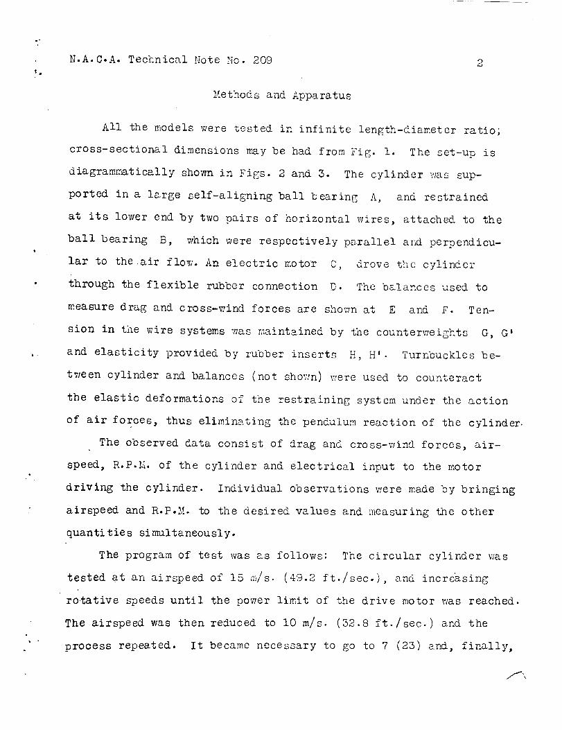
All the models were tested in infinite length-diameter ratio;
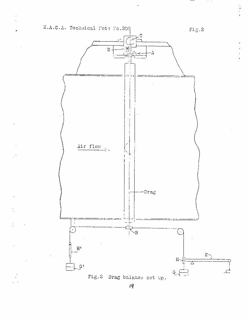
cross-sectional dimensions may be had from Fig. I. The set-up is
diagrammatically shown in Figs. 2 and 3. The cylinder was sup-
ported in a large self-aligning ball bearing A, and restrained
at its lower end by two pairs of horizontal wires, attached to the
ball bearing B, which were respectively parallel and perpendicu-
lar to the air flow. An electric motor C, drove the cylinder
through the flexible rubber connection D. The balances used to
measure drag and cross-wind forces are shown at E and F. Ten-
sion in the wire systems was maintained by the counterweights G, G'
and elasticity provided by rubber inserts H, H'. Turnbuckles be-
tween cylinder and balances (not shown) v_ere used to counteract
the elastic deformations of the restraining system under the action
of air forces, thus eliminating the pendulum reaction of the cylinder.
The observed data consist of drag and cross-wind forces, air-
speed, R.P.N. of the cylinder and electrical input to the motor
driving the cylinder. Individual observations were made by bringing
airspeed and R.P°N. to the desired values and measuring the other
quanti tie s si multaneouslyo
The program of test was as follows: The circular cylinder was
tested at an airspeed of 15 m/s (49.2 ft./sec.), and increasing
rotative speeds until the power limit of the drive motor was reached.
The airspeed was then reduced to I0 m/s. (3_.8 ft./sec.) and the
process repeated. It became necessary to go to 7 (23) a_i, finally,

,o
_m
N.A.C.A. Technical Note No. 209 3
5 m/s. (16.4 ft./see.) in order to reach a maximum "lift/drag" ratio.
The performance of the cross cylinder, at 15 m/s. (49.2 ft./
sec.), was very erratic. A _._rkcd hysteresis loop made its appear-
ance in the vector diagram of resultant air force and, when excess-
ive vibration was encountered at 3000 R.P.I,i. and l0 m/s. (32.8 ft./
sec.) airspeed, the work on this model vras discontinued.
The first test on the compound strut, in which the gap between
cylinder and fairing was 1/8", showed this combination to be infer-
ior to the oircular cylinder when considered as an airfoil. A
large scale effect was also found, coefficients for a fixed ratio of
peripheral speed to airspeed varying with the airspeed. Tests with
a 3/8 I' gap were made next but such a large increase of drag was
found that no further combinations were tried.
After the completion of the force measurements, apparatus was
installed to allow the introduction of smoke filaments into the
aizstream just in front of the cylinder and a series of photographs
were taken at various combinations of rotative and airspeeds.
Reduction of Data - Presentation of Results
The air forces acting on the cylinder were assumed to be sym-
metrical about a horizontal plane through t_he tunnel axis, i.e.,
the resultant air force was ausumed to act in this plane. The di-
mensions.of the set-up were such that a factor 1.965 had to be ap-
plied to the measured forces to give true forces acting on the cyl-
inder. Coefficients were derived on a basis of projected area of

°o
N.A.C.A. Technical Note No. 2.09
ql
4
the cylinder as follows:
CD_ DqS
wherein q is the dynamic pressure, S the projected area of the
cylinder, D the drag force, CWF the cross-wind, or "lift" force,
V' the peripheral speed and V the airspeed.
The data from tests on the circular cylinder are given in
Tables I and II. Fig. 4 is a vector diagram which shows the vari-
ations of resultant as well as component forces throughout the
range explored, Fig. 5 indicates the variation of cross-wind force
with the ratio of peripheral to translational speed, and Fig. 6
shows the power necessary for rotation at zero and 15 m/s (49.2 ft./
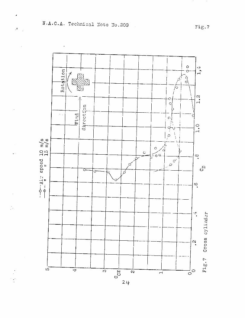
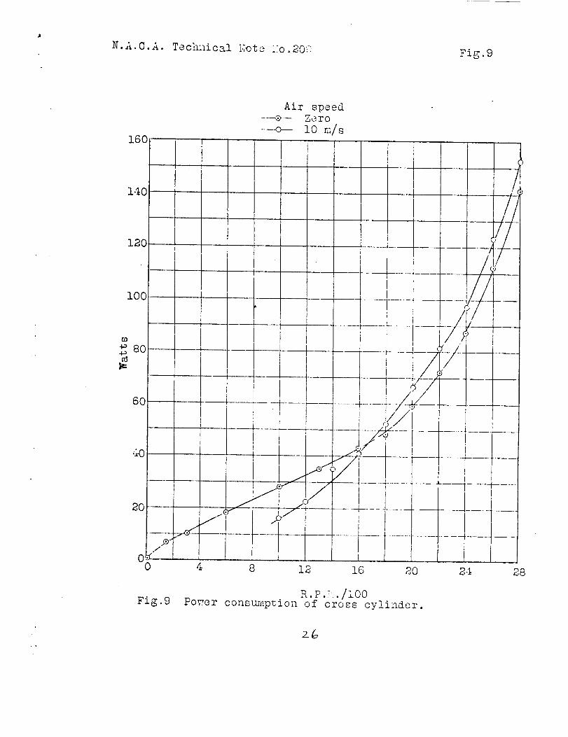
sec.) airspeed. Corresponding data on the cross cylinder are given
in Tables III and IV; Figs. 7, 8 and 9 are the vector diagram, plot
of cross-wind force against speed ratio, and power consumption
against R.P.M., respectively. The data taken on the compound strut
with 1/8" gap, are given in Tables V and VI; Figs. lO, II and 12
are plotted therefrom. Results from the second strut combination
are given in Table VII and plotted in Figs. 13 and 14.
Discussion
As no mathematical or physical analysis of the results has
been attempted, as yet, this discussion will, necessarily, consist

Qm
N.A.C'A. Technical Note No. 209 5
in callir_ the reader's attention to those points _hich seem of
greatest importance. Let us consider, first, the tests of the
circular cylinder.
The sudden appearance of the cross-wind force at z = 0.5
seems so definitely established that mere coincidence is doubtful.
Unfortunately, no ztudy of the smoke flow was made in this range
so it is not known whether there is an abrupt change in the flow
pattern to account for the phenomenon.
Beyond the ratio r = 0.5, the cross-wind force increases
steadily through quite a range in which there is practically no
variation in drag, the value of the lattcr re,,_aining constant be-
tween r = 0.5 and 2.0. "Jith values of r greater than 2.0 the
drag increases and the maximum ratio of lift to dra_g (?.8) is at-
tained when r = 2.5, approximately. It is noted that the drag
coefficient at this point is almost identical with that of the
stationary cylinder.
The high values of CCW result, of course, from the very un-
symmetric velocity distribution around the cylinder. The smoke
photographs (Figs. 15, 16 and l?) clearly depict the Gradual dis -r
tortion of the symmetrical flow pattern with increasing rotation
and the building up of a very high velocity region opposite one
of considerably reduced velocity. Thus the rotation produces the
same sort of velocity distribution as does camber in the case of
an airfoil. The greater dissymmetry of this flow, as compared to
that about an airfoil, is undoubtedly due to the fact that the

" N.A.C:A" Technical Note No. 2096
proportionate increase and decrease of the free stream velocity is
considerably augmented by the rotation.
In connection with the variation of drag, the following points
are noted: The smoke photographs show that at small values of r
the groups of streamlines from the two sides of the cylinder do not
diverge so markedly as is the case with the motionless cylinder.
This accounts for the first reduction of drag. Through the range
in which CD remains constant, although CCW increases rapidly,
there must be balance of the changes in the flow pattern around the
upstream and downstream halves of the cylinder. VJith further in-
crease of rotative speed, it is seen (Fig. 17) that the streamlines
from the high velocity side wrap farther and farther around the
cylinder, It seems probable that as the stagnation point moves
back along the low velocity side, it will finally meet and merge
with the point at which the two groups of streamlines reunite. A
completely different type of flow will naturally result and the
rapid increase of drag and reduction in the rate of increase of
lift are its characteristics.
The fact that the power input is smaller with moving than sta-
tionary air indicates a reduction of air friction. This would be
expected as the relative velocity of air to cylinder is reduced,
around most of the circumference, by the rotation.
The characteristics of the cross cylinder, throughout the range
covered, were very irregular. The relatively high power required
to rotate this model prevented the reaching of high values of r.
%B
N.A.C.A. Technical Note No. 209
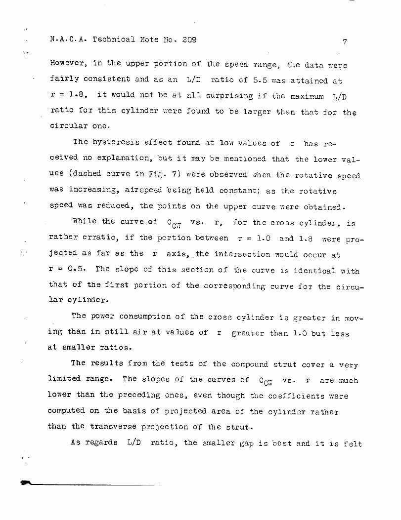
However, in the upper portion of the speed range, the data were
fairly consistent and as an L/D ratio of 5.5 was attained at
r = 1.8, it would not be at all surprising if the maximum L/D
ratio for this cylinder were found to be larger than that for the
circular one.
The hysteresis effect found at low values of r has re-
ceived no explanation, but it may be mentioned that the lower val-
ues (dashed curve in Fig. 7) were observed when the rotative speed
was increasing, airspeed being held Constant; as the rotative
speed was reduced, the points on the upper curve were obtained.
While the curve of CCV ' vs. r, for the cross cylinder, is
rather erratic, if the portion betv_een r = !.0 and 1.8 were pro-
jeoted as far as the r axis, the intersection would occur at
r = 0.5. The slope of this section of the curve is identical with
that of the first portion of the corresponding curve for the circu-
lar cylinder,
The power consumption of the cross cylinder is greater in mov-
ing than in still air at values of r greater than 1.O but less
at smaller ratios.
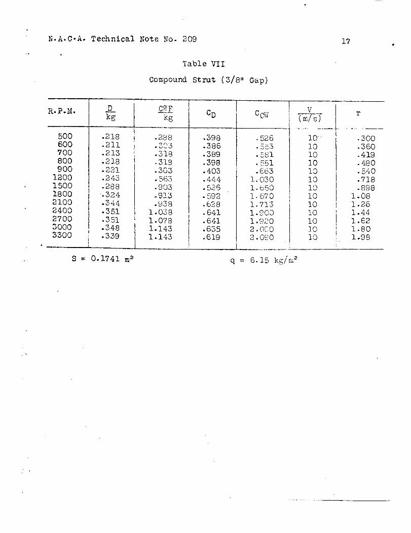
The results from the tests of the compound strut cover a very
limited range. The slopes of the curves of COW vs. r are much
lower than the preceding ones, even though the coefficients were
computed on the basis of projected area of the cylinder rather
than the transverse projection of the strut.
As regards L/D ratio, the smaller gap is best and it is felt

_" N.A.C.A- Technical Note }7o. 209 8
that if it had been possible to use still smaller clearance and
practically eliminate any flow through the gap, rauch better results
might have been realized. It is evident that with any appreciable
gap, the circulation around the entire assembly is reduced by the
flow between the cylinder and fairing.
It will be seen that lift appears at the smallest values of
r observed.
Conclusions
The controlled combination of translational and circulatory
velocities has shown that -
1. The air forces obtainable by superpasition of a circula-
tory flow upon the one arising from translation of a doubly symmet-
ric body are several times Greater than have ever been observed
on any unsymmetric body.
2. Lift increases with circulation, although the law connect-
ing the variables is not definitely established or its limits of
application known.
3. The ratc of increase of lift with _-ate of revolution seems
practically independent of the shape of the rotating body, provided
it is symmetrical about both axes in its plane of rotation, except
at the very low speeds.
4. The drag of a blunt body in rectilinear air flow may be
considerably reduced by the addition of a circulatory flow. (It
seems probable that this results in a reduction in the width of the

N A.C-A. Technical Note No. _0_ 9
turbulent area behind the cylindel* before any "downwash" or change
in the direction of the discharged airstream appears• Th_s is in
accord with the Karman theory of resistance as given in Joukowski's
"Aerodynamique, " p.203).
Bibliography
Reference I - Technical Report No. 116: Applications of !_odern
Hydrodynamics to Aeronautics, by L. Prandtl. 1921.
| t ! __

N.A C.A Technical Uote -7o. _9 I0
!.
R.P.Z.
25
50O9C0
lOSO
1]_15
12 4.0
1300
1300
1400
1500
1500
1600
1600
1700
1700
1700
1780
1800
1900
1900
1900
2000
2080
2100
2200
2220
2500
2420
2 5002 6002620
2700
1300150017001900
210023002 5OO27002900
kg
1.136
1.1361.026
.942
.852
.777
..754
.747
.740
.74"3
.740
.74.4
.7 44•759
•751
.750
.751
•754
.75?.751.757
.759
.765
.764
.764
.787
•7 '72.754
•742.729
•724.710
.353
.351
.338
.331
.324
.332
.334
.346
Tablc I
Circular Cylinder
-.0]0
+.010
-.020
-.022
-.007
+.003
•018
.043
.150
.285
.305
.400
.453
.608
.625
.599
.660
.673
.798
.815
.753.873.869
.997
!.073
1.158
1.188
1.278
1.338
1.468
1.303
1.578
+.308
•418
•636
•758
,978
1.083
1.295
1.403
I •443
CD
.925
.925.835.766.693• 63::3.614.608• 602.6O5• 602.6O5
.605•618
.611
.610
.611
.614
.616
.611
.615
•613
•622.622.622•64.0.628.614
.604Q,z
• 5,j _.J
,589
•578
.646
.642
.618.605.5S9
.593• 607.611.633
CO:."
-.008
- • 008-. 016
-. 0!9
-. hOG
+. 002
.014
•035
.122
.230
.248
.569
• 495• 508.497
.537
•546
.650
•6_3
.617
.710
.706
.811
•873
•942.967
! •040
i. 089
1.194
I. O6O
I •284
,563
•764
I. 163
1.386
1•789
I •980
2,3622. 564
2.639
V
77r,__try
15
1515
15
15
15
15
!5
15
15
15
15
15
1515
15
15
15
15
15
15
15
1515
15
15
15
15
15
15
15
15
I0
I0
I0
I0
!0
"I0
I0
I0
I0
.010
.200
.360• 4O8..t;60.496• 520• 520• 560.600• 600.640
.640
.680• 680•680• t165
•720•760
.760
.760
.800
.832
.84O
.880
.888
.920
.968
1.000
1. 040
1.048
1.080
•780
.900
1. O20
1. 140
1.260
1.380
I. 500
i .620
I. 7 40

• N.A.C.A. Technical Note No. 209 II
Table I - Continued.
Ciccular Cyliner
1800
2100
2400
2700
3000
3300
Z600
1800
2100
2400
2700
3000
3300
3600
D__kg
.085• 105.!30_IE1.168.183.196
.167
•1Y3.181
.197
.222
.256
.287
i
cw__Zkg
.605
.820
.9951.1i01. 1701.2501.295
CD
•622
•769
.952
i .105
1.230! .376
I •434
I
Ccw
4.436.00
7.28
8.138.57
9.15
9.48
V
5
5
.660
.8g01.1401. 365t.7001.9452.210
.624• 64G.676.736.829
.956I • 070
J
2.463.2!4.265.106.357.268.25
5555
77777
77
r
2 .!62.512.873.253 • 593.954.52
1.54! .792.052.502.56
2.823.07
0.1741 m 2
1.535 kg/m 2 (5 m/s), 3.01 kg/m 2 (7 re�s), 6.15 kg/m 2 (10 m/s)
and 13.81 kg/m 2 (15 m/s).

N.A.C.A. Technical I_ote I_o. 2C9
Power
Airspeed = 0
Table
Consumption of
II
Circular Cylinder
Airspeed = m/s
12
R.P._.
29O580
8851190
1400
1775
2260
2810
3140
3475
Watts
6.0
I0.0
11.5
19:024.0
27.0
40.1
51 •8
68.0
89.2
R.P .M.
!0201115
I_40
15OO
1700
1900
2080
22,20
2300
2420
$500
2800
2700
3000
Watts
14.515.5
17.3
2,3 -8
26.028.431.8
28.630-231 o
33.634.8
37.2
44-8

N.A.C.A. Technical Note No. 209 13
Table III
Cross Cylinder
R. P.M.
01501502O02O030O3O04OO4OO5O060O60070084O85O
I000I0001200120014001400160016001600180018002000200022002200
2400
2400260028003000
1800200022002400
2600
_.
q=
D
kg
.594
.723
•740
,763
.782
.702
.731
•618
,640
•.655
•518
• 585• 564
•548•562
•493
•548
C3:Fkg
+. 018•175
•]75
•163
•].65
•355
.305
.430
.465
•530
.475
.480
.495
-395
•475
.205
.485
CD
1.0871.322
1.353
1.396
I. 430
1.284
1.337
1.130
I .]70
1.198
.947
1.070
1 •032
1.000
1. 028
.9021. 000
,458
.515
•420
.472
.405•460
•465,440
.450
.417
.428
.373
.402
.343
.374.372• 372.577
1,079
1.029
.994
-980
,966
.260
•545
.565
,700
•435
.795
.740
.850
.940
i. 010
I. 0951.305
1.220
I. 475
1.425I. 630
1.860
2.075
1.205
1,3!0
I. 440
1,605
1.805
.837
.941
,768
.862
.740
.841
.850
.804
.823
.762
.782
.682
,735
.627,684
-680
.680.689
.$79.838.8!0.798•787
CCW
-0_,0
.320
.320•298.302.649• 557.786.850• 9G9.838.878.905.722.8_8
.375
.887
.475
•996
.667
! .280
.796
I. ,%54
1.353
1. 554
1.720
1. 847
2-000
2. 4202.2502. 6952.6052.9803.400
3. 790
.981
I. 067
I. 174
I. 307
1.4700.1741 m 2
6.15 kg/m _ (I0 m/s), 13.81 kg/m _ (15 m/s)
V
i0
I0
I0
I0
I0
I0
I0
i0
I0
!0
i0
I0
I0
I0
I0
!0
I0
I0
I0
I0
I0
I0
I0
I0
I0
I0
i0
I0
I0
I0
I0
I0
I0
I0
I0
1515
15
15
15
r
•;000•090
.090
•120
•120
•180
.180
.240
.240
.300
.360
.360
.419•503
.509
•598•598.718
.718
.838
.838
.958
.958.9 58
1.08
! .08
1-20
1.20
I- 32I ,32
1.44
!.44
I. 56
1-68
1.80
.720
.800
.880
.960
I .040

N.A.C.A. Technical Note No. ?09 14
Power
Airspeed = 0
Table IV
Consumption of Cross
Airspeed =: I0 m/s
Cylinder
AiT speed = 15 m/s
R. P._{.
!000
1200
1400
1600
1800
2000
22002400
2600
28O0
Watt s
16.125.855-04:2.053 -966.68t.296.6
125 -215,3-2
R.P. DI. Watts R. P-Y..
140
30060O
!000
1500
1600
i800
2000
2200
24OO
2600
28O0
6.B
I0.,_
18.0
28.0
55.0
43.0
48.0
59.4
?2.0
87 .I
I12.5
141.0
1800
20002100
2200
$400
2600
Uat t s
62,4
74-0
84- 0
88 -3
105.0
151.0
138.0

N.A.C.A. Technical Note No. 209 15
Table V
Compound StrutGap = 1/8"
R.P.M.
0
55
105
150
2OO
250
3OO
350
4OO
450
45O
5OO
600
BOO
700
9OO
1200
1500
1600
1700
1900
2100
2400
27003000
0
50O
700
9OO
900
II00
1200
1300
1400
1600
1600
1800
2000
D
kg
•109
•I13
.i14
.!!4
.115
.115
.i15
,115
•117
•119
•119
.121
•125
.128
.128
.125
.125.144• 149
.165
.175
.214
.251
.256
.2 50
.565
•557
•557
•545
.552
•533
.535
•530
.537
•515
.530
.532•532
CWFkg
i
.OOO•0_3.016
.020
.026
.0_8•093.153.138
•193
.250
.218
.355
•278
.333
.375
.440
.635
.720
.730.730.770.890
.920
.885
- .140
-.125
-.030
+•065
+.II0
+.185
•290
.550
•675
•615
.950
1.025
CD
.199
.206• 208.208
.210
.210
.210
.210
•214.217.217
.22i
.228-234-234.228•225.263
.272•301
.320•391
•458
.467
.457
.254
.255
.255
.245• 249.240.241.239•242• 232.259.240.240
CCW
.000
. O0%•029.036.066
.124
.170
.243• 2 52.552
•457
.398
.611
.508
.608
.685
.8031.160
1.314
!. 332I
1.332 I1. 406
I
1.6251.680
1. 616
i
- 063 '
•056.013
.029
.050
.085
-131
.158
.304
.277-428
, 1462 i
I0
I0
I0
I0
I0
i0
I0
I0
I0
I0
I0
I0
I0
I0
I0
I0
I0
10
I0
I0
I0
i0
I0
I0
I0
2O2O2O2O20
2O2O2O2O2O
202O20
0• 02.06• 09.12
.15
.1821,24.27.27.30.36.36.42
.54
.72
.90
.96
1.02
! .14
! .27I .45
1.63
1.81
.15
.21
.27
-27
.33
.36
.39
.42
•48
.48
.592
•603
S = 0.1741 m 2 q = 6.15 kg/m 2 (I0 m/s), 13.81 kg/m 2 (20 m/s).
• °

N.A.C.A. Technical Note No. 209 16
Tabl e Vi
Power Consumption of Compound Strut.
Gap = I/8"
Airspeed = 0 Airspeed = I0 m/s
R.P.M.
I00
3O0
5OO
8O0
II00
1400
17002000
2300
2600
2900
Watt s
2.1
3.0
5.6
7.6
12.5
18.0
33.8
32.2
41.6
46.4
50.4
R. P.._£.
1CO300500800
1100140017002000230026002900
Watts
2.84.05.69.5
15.618.625.935.,240,845.653.6
N.A.C.A. Technical Note No. 209
Table VII
Compound Strut (3/8" Gap)
17
R.P._.
5OO
60O
7OO
8OO
9OO
1200
1500
18002100
2400
2700
S000
3300
D
kg
.218
.211
.213
.218
.221
•243
.288
.324
.344
.351
•351.348
.339
S = 0.1741 m _
CWF
kgCD c@y
V
•3OO
•360
.419
•480
•540
.718I .898I 1.08
! 1.26' 1.44I 1.62
I 1.80l
1.98i
q = 6.15 kg/m 2
.288'7 f'_'
•318
.318
-303• 563.903-933.938
1.038
1.078
1.143
1.143
.398.386• 389•398.403.444• 526• 592• 628.641•641
.635• 619
.526
• ,j_j3
.581
•581
.663
i. 030
1.650
I. 6701.713
1.900
1 .°20
2. O.C.,02. 090
........
F lOI0
i0
I0
I0
I0
I0
i0I0
1 aolO10
. i ao
i

N.A.C.A. Technical i'_ote i,_o.209 Fig.l
4 I/2"D---_
Circular cylinder Cross cylinder
Fig.l
ii i/'i"
/ ,"/ :>, x >// /,.2.'/.
v//_ /,,, ./,. ,,. /,?',.,
Compound st_ut/
19"R
Section of cylinders and struts used in tests.
N.A.C.A. Technical !_ot_ _. Yo.209Fig.2
Air flo_
I
H'
-.T
I_
<-B
Fig.2
rag
Drag balance set up.
v_0I
lq

N. A. C. A. Technical hote 1i,:o.809i
I
wind
O]'C I
III
I
//
/J
//"
Fig.3
H'
Fig. 3 Cross-wind
zO
forcc set up.
F%
___Ir__

iI.A.C._,. ,_,c_inzc_tl Zoto Yo 209 Fi _....
i0
9
S
?
6
5
CC-:r
.I
3
1
0
0
iI
I
i i
i
Fig " Circular cylindcr. 2_I

N.A.C.A. Technical Yote i_To.209Fig.5
i0
9
8
7
6
5
CCW
4
3
2
__
0
-1
0
J
I
I
+ Air speed 5 m/s
o . " i0 "
x . " 15 "
Rot _tion
1.6
r8. ,I 3.2
Fig.5 Circular cylinder.
Z2-

,$
i_.A.C.A.
OhO
c)o --
00
Tochnical
\
.._c,q\_..
P0CO
0qO
Iri
Fir_hOtO
O0
oO
_qC)
q_
.rqrq
0
,-..q
0
._.._0
tH0
0
a.oO.fZ
co
0o
_q¢)
o
_0
c9
[=,
_3
I
N.A.C.A. Technical Note :,To.209Fig.7
CO _D
0 tOr-.4 ,-I
"d_D
•_.t =
tf?
I t' oI .... t--O-
t
I ,I f', i
,P 1i e "
O__ i_Q t,¢
._r-" i
I ,¢_ _
I
i
oa
o
CO
_D
i
00
Ao
M
o3
°,-I
r--t
0
0
0

i_.A. C. h. Technical Foto i'o. ;]09 Fi S. 8
,t
5
C cw
00
Xir spued I0 m/s" ,, 15 "
I
ii
!
_s _-/.W_/__J
.......V
.,'<
c./ ip
------_---r-o)_..............I I i ,I I i q
! ; l...... O/----n----- -_-----_ ...., r 1 6 t
' t _ 0/'/ 1' ' P I
-,t-- _--?---_1_-."--r-------_ r---- -
i I , -d"_: t I IC>'_;.-+mT_--_,S"_:,_------*--,-- -i..... 4- ........... _.........
.;_o "n I i .o] I I
...._.,_]__..___j__ __..]__ _...j..0" j [ i !
2 + ; '_-:_ + ,..... j........,.........
.4 .8 1.2 1.6 2.0r
Fig.8 Cross cylinder.
2-5
.B
N.A.C A T_cnnlcal i,7ote i;o.2,0!_Fig.9
160
l.iO
120
i0(
CO
+_ 8(
6O
4O
_0 ......
,/0 _-0
Fig.9
Air speed---_-- Zero
---o-- I0 m/s
I
7-7?
4 /
i
4 8 12 16 20 2-I 2_8
R. P. ".•/i00Power constumption of cross cylinder.
z&

N.A.O.A. Technical Note [email protected]
I
CCw
5
4
i
0
-O-- Air speed i0 m/s--_.¢- ,, i, _0 "
0 .o
IIiI
Ii i
R ration
i
W_ud d._.rect J,on---
i G_;P)
gh
.4
iiI
i .....
.6
CD
II
i....._ ....Iii
!
.8 1.0
Fig.lO Compound strut.Gap 1/8"
z7

N.A.O.A. Technical ];ote hTo.209• r •FI_ Ii
5
speed I0 m/s" 20 "
4
CCW
2
1
/.Io
o f.jooj, ..o o__ _0 .4 .8
i G _p
_0 f_ )
r
Ii
1.2 1.8 2.0
Fig-ll Compotu_-d strut.Gap 1/8"

' N.A.C.A. Tachnical i,7otc }o.309
C l
O
_ is.l?,
,. 2_

N.A.C.A, Technical Note No.809Fig. 13
--o--Air speed i0 m/s
_ _ _
C cw
4
3
2
1
di:
4 i
i
,8
Fig.13 Compound strut.Gap 3/8"
• °
_0

N.A.O.A. Technical Note 11o.209 Fig.l,l
5--o--Air speed i0 m/s
4
3
CCW
2
I
00
Fig.14
/0_.I0 /
II
.4 .8 1.2r
1.6 2.0
Compound strut.Gap 3/8"
3_

N.A.C.A. Technlc-_l _ote _,;::.Z08 Figs.!5,16 & 17
Fig. 15 600 R.P.m. V': .Tq
52--