Nabinagar Power Generation Co. Pvt. Ltd. (JV between 400/132kV Switchyard at Nabinagar STPP...
44
Transcript of Nabinagar Power Generation Co. Pvt. Ltd. (JV between 400/132kV Switchyard at Nabinagar STPP...

PROJECT: 400/132kV Switchyard at Nabinagar STPP CUSTOMER: Nabinagar Power Generating Company Ltd. Technical Specification of 400,132,33 kV post Insulators TB-350-316-004A Section-1: Scope, Specific Technical Requirements & Quantities REV.00
Page 1 of 2
SECTION 1
SCOPE, SPECIFIC TECHNICAL REQUIREMENTS AND QUANTITIES. 1.0 SCOPE
This technical specification covers the requirements of design, manufacture, testing at works, packing and dispatch of Solid Core Bus Post Insulators complete with accessories. This section covers the specific technical requirements of Bus Post Insulators. In case of any discrepancies between the requirements mentioned in this section and those specified in the following sections of this specification, the specifications given herein shall prevail and shall be treated as binding requirements. No deviation from the requirements specified in various clauses of this specification shall be allowed. A certificate to this effect shall have to be furnished along with the offer as per attached Annexure-1.
1.1 The equipment is required for the following project.
Name of Customer :
Nabinagar Power Generation Co. Pvt. Ltd. (JV between NTPC and Bihar State electricity Board)
Name of Project : 400/132 kV Switchyard at Nabinagar STPP and
extn. at 400 kV Nabinagar TPP (BRBCL) Refer Section - 3 for Project Details and General Specifications. 1.2 SPECIFIC TECHNICAL REQUIREMENTS
Sl. No Parameter Data 1 Type Solid Core type 2 Voltage class (kV) 400 145 33 3 Dry and wet one minute power frequency withstand voltage
(kVp) 680 275 95
4 Dry lightning impulse withstand voltage (kVp) ±1550 ± 650 170 5 Wet switching surge withstand voltage (kVp) ±1175 NA NA 6 Max. RIV (in microV) between 0.5Mhz to 2.0Mhz at 266kV
(rms) for 400kV and 92 kV (rms) for 132kV phase to ground voltage
1000 1000 NA
7 Corona extinction voltage (kV rms) 320 - NA 8 Total min. cantilever strength (kN) 8 6 6 9 Minimum torsional moment (kgm) 600 500 300 10 Total height of insulator (mm) 3650 1500 500 11 P.C.D Top (mm) 127 127 76 Bottom (mm) 300 225 76
12 No. of bolts Top 4 4 4 Bottom 8 4 4
13 Diameter of bolt holes Top (Tapped hole) M16 M16 M12 Bottom (mm) Dia 18 Dia 18 M12
14 Pollution level as per IEC-815 Heavy (III) 15 Min. total creepage distance (mm) 10500 3625 900

PROJECT: 400/132kV Switchyard at Nabinagar STPP CUSTOMER: Nabinagar Power Generating Company Ltd. Technical Specification of 400,132,33 kV post Insulators TB-350-316-004A Section-1: Scope, Specific Technical Requirements & Quantities REV.00
Page 2 of 2
1.3 QUANTITIES
As per Annexure-A
1.4 TYPE TESTS The post insulators to be supplied shall be of type tested design. During detail engineering, the
Bidder / Contractor shall furnish for Owner’s approval the reports of all the type tests as listed in this specification and carried out within last ten years from the date of bid opening. Date of bid opening is . 29.06.2011. These reports should be for the test conducted on the equipment similar to those proposed to be supplied under this contract and the test(s) should have been either conducted at an independent laboratory or should have been witnessed by a client.
However if contractor is not able to submit report of type test(s) conducted in last ten years from
the date of bid opening, or in case of type test report(s) are not found to be meeting the specification requirements, the contractor shall conduct all such tests under this contract at no additional cost to the owner either at third party lab or in presence of client/owners representative and submit the reports for approval.
All acceptance and routine tests as per specification and relevant standards shall be carried out. Charges for these shall be deemed to be included in the equipment price.
The type test reports once approved for any projects shall be treated as reference. For subsequent
projects of NTPC, an endorsement sheet will be furnished by the manufacturer confirming similarity and “No design Change”. Minor changes if any shall be highlighted on the endorsement sheet.

400/132 kV s/s at Nabinagar STPP
Bill of Quantities for 400/132/33 kV Post Insulators Annexure-A
S. No. Item DescriptionNabinagar
STPPNabinagar TPP Total
1. 400kV, 8kN Post Insulators without corona ring (for isolators & wavetrap) along with hard ware for inter-unit connection and hardware for fixing to mounting structure
364 48 412
2. 400kV, 8kN Post Insulators with corona ring * (for bus support) along with hard ware for inter-unit connection and hardware for fixing to mounting structure
275 12 287
3. 132kV, 6kN Post Insulators (for isolators) including Hardware for interconnecting the insulator units and for fixing the insulator to structure
178 0 178
4. 132kV, 6kN Post Insulators (for bus support) including Hardware forinterconnecting the insulator units and for fixing the insulator to structure
31 0 31
5. 33kV, 6kN Post Insulators (for isolators) including Hardware forinterconnecting the insulator units and for fixing the insulator to structure
44 0 44
6. 33kV,6kN Post Insulators (for bus support) including Hardware forinterconnecting the insulator units and for fixing the insulator to structure
6 0 6
Note:
1
2
3
4
5
Quantity (Nos.)
For 400kV Solid Core Bus Post Insulators, if corona extinction voltage is to be achieved with the help of corona ring or any other similar device, the same shall be deemed to be included in the scope of the bidder without any price implication.
Quantity of post insulators may vary by -10% to +25% for any of the items during contract execution.
* If corona extinction voltage is achieved without any corona ring or other similar device, the purchaser reserves the option for procuring insulators without corona ring.The supply of insulators shall also include supply of hardware, comprising bolts, nuts and washers, for joining the units of multiunit insulators as well for fixing to support structure. The length of bolts for fixing to hardware shall be decided on the basis of 12-mm thickness of top plate of mounting structure.
The post insulators shall be suitable for hot line washing.

PROJECT: 400/132kV Switchyard at Nabinagar STPP CUSTOMER: Nabinagar Power Generating Company Ltd. Technical Specification of 400,132,33 kV post Insulators TB-350-316-004A Section-2: Equipment Specification REV.00
Page | 1
SECTION 2
EQUIPMENT SPECIFICATION 2.0 GENERAL
This section covers the standard technical specification for Bus Post Insulator.
2.1 TECHNICAL REQUIREMENTS
The technical requirements shall be as per the SPECIFIC TECHNICAL REQUIREMENTS of Section-1.
2.2 GENERAL TECHNICAL REQUIREMENTS
The post insulators shall conform in general to latest IEC – 273, IS: 2544, IEC-168 and IEC-815.
2.3 CONSTRUCTIONAL FEATURES: 2.3.1 Post type insulators shall be solid core type and shall consist of a porcelain part
permanently secured in a metal base to be mounted on the supporting structures. They shall be capable of being mounted upright. They shall be designed to withstand any shocks to which they may be subjected to by the operation of the associated equipment.
2.3.2 Porcelain used shall be homogeneous, free from lamination, cavities and other flaws or
imperfections that might affect the mechanical or dielectric quality and shall be thoroughly verified, tough and impervious to moisture.
2.3.3 Unless otherwise specified, the glazing shall be of uniform brown colour only. The glazing
of the porcelain shall be free from blisters, burrs and other similar defects. 2.3.4 The insulators shall have alternate long and short sheds with aerodynamic profile. The shed
profile shall also meet the requirements of IEC-815 for the specified pollution level. 2.3.5 When operating at rated voltage there shall be no electric discharge between conductor and
insulators which would cause corrosion or injury to conductors or insulators by the formation of substance produced by chemical action.
2.3.6 The design of the insulators shall be such that stresses due to expansion and contraction in
any part of the insulators shall not lead to deterioration. 2.3.7 All ferrous parts shall be hot dip galvanized in accordance with the latest edition of IS:
2633, & IS: 4579. The zinc used for galvanizing shall be grade Zn 99.95 as per IS: 209. The Zinc coating shall be uniform, adherent smooth, reasonably bright, continuous and free from imperfections such as flux ash, rust stains bulky white deposits and blisters. The metal parts shall not produce any noise generating corona under the operating conditions.
2.3.8 a) Every bolt shall be provided with a steel washer under the nut so that part of the threaded portion of the bolts is within the thickness of the parts bolted together.
b) Flat washer shall be circular of a diameter 3.5 times that of bolt and of suitable thickness. Where bolts heads/nuts bear upon the beveled surfaces they shall be provided with square tapered washers of suitable thickness to afford a seating square with the axis of the bolt.

PROJECT: 400/132kV Switchyard at Nabinagar STPP CUSTOMER: Nabinagar Power Generating Company Ltd. Technical Specification of 400,132,33 kV post Insulators TB-350-316-004A Section-2: Equipment Specification REV.00
Page | 2
c) All bolts and nuts shall be of steel with well formed hexagonal heads forged from the solid and shall be hot dip galvanised. The nuts shall be good fit on the bolts and two clear threads shall show through the nut when it has been finally tightened up.
All ferrous parts shall be hot dip galvanized in accordance with the latest edition Bidder shall make available data on all the essential features of design including the method of assembly of shells and metals parts, number of shells per insulator, the manner in which mechanical stresses are transmitter through shells to adjacent parts, provision for meeting expansion stresses, results of corona and thermal shock tests, recommended working strength and any special design or arrangement employed to increase life under service conditions.
2.4 Tests 2.4.1 The post insulators shall confirm to type tests and acceptance, sample and routine tests as per IS: 2544 and IEC-60168 shall be carried out. 2.4.2 In addition to acceptance/ sample/routine tests as per IS: 2544 and IEC-168, the following
tests shall also be carried out. a) Ultrasonic tests on all cutshells as routine check.
b) Visual examination and magnaflux test on all flanges prior to fixing.
c) Check for uniformity of thickness and weight of zinc coating as a sample test from each
lot of flanges prior to fixing.
d) Bending load test shall be carried out at 50% minimum failing load in four directions as a routine test.
e) Bending load in four directions at 100% minimum bending load guaranteed on samples as per clause-2.3 of IEC. Subsequently this post insulator shall not be used.
f) Tests for deflection measurement at 20, 50, 70% of specified minimum failing load on
sample.
2.4.3 The post insulator shall confirm to following type tests as applicable according to voltage class:
a) Switching Impulse withstand test (dry and wet) for 400 kV insulator only b) Lighting impulse withstand test (dry) c) Power frequency withstand test (dry & wet) d) Measurement of RIV (dry) e) Corona extinction voltage test for 400 kV insulator only f) Test for deflection under load g) Test for mechanical strength
2.5 The other requirements of insulators as given in clause 3.15,3.10,Annexure-A&B of
section 3 shall also be applicable.
PROJECT: 400/132kV Switchyard at Nabinagar STPP CUSTOMER: Nabinagar Power Generating Company Ltd.
Section 3 Page 1 of 20
SECTION- 3 PROJECT DETAILS & GENERAL TECHNICAL REQUIREMENTS
3.0 GENERAL
This section stipulates the General Technical Requirements under the Contract and will form an integral part of the Technical Specification.
The provisions under this section are intended to supplement general requirements for the materials, equipment and services covered under other sections of tender documents and are not exclusive. However in case of conflict between the requirements specified in this section and requirements specified under other sections, the requirements specified under respective sections shall prevail.
3.1 PROJECT INFORMATION:
Particular Details a) Customer Nabinagar Power Generating Company Ltd. (NPGC)
(A joint venture of NTPC Ltd. and Bihar State Electricity Board)
b) Project Title
400/132 kV Switchyard including 400 kV & 33 kV Transmission Lines for Nabinagar Super Thermal Power Project (3X660 MW) at Nabinagar Bihar and extension of two line bays at 4X250MW Nabinagar TPP.
c) Location
Nabinagar STPP (i.) Place : Nabinagar (ii) District :Aurangabad (iii.) State :Bihar
Nabinagar TPP (BRBCL) (i.) Place : Nabinagar (ii) District :Aurangabad (iii.) State :Bihar
d) Nearest Road Head
National Highway-2 (Approximately 25 kms from National highway)
e) Nearest Rail Head
Dehri-On-Sone (Approximately 30 kms from Railway Station)
SITE CONDITIONS a) Max. ambient air temp. 50C b) Min. ambient air temp. 0C c) Max. design ambient
temp. 50C
d) Design reference RH 100 % e) Altitude <500 MSL f) Pollution Severity High Pollution level (25mm/kV) g) Seismic Zone
Zone-III
WIND DATA a) Basic Wind speed 47m/sec b) The risk co-efficient
(K1) 1.07
c) Category of terrain Category-2

PROJECT: 400/132kV Switchyard at Nabinagar STPP CUSTOMER: Nabinagar Power Generating Company Ltd.
Section 3 Page 2 of 20
d) Maximum wind pressure on steel members
1500 N/m2
3.1.1 SYSTEM PARAMETERS: Sl.No. Parameters 400 kV 132 kV 33 kV 1 Highest system voltage 420 kV rms 145 kVrms 36 kVrms 2 Lightning Impulse voltage ±1425kVp ± 650kVp ± 170kVp 3 Switching impulse voltage ±1050kVp -- -- 4 Power frequency withstand for 1
min (rms) 630 kV(rms) 275 kV(rms) 70 kV(rms)
5 Max. fault level (1 sec.) 50 kA 31.5kA 25 kA 6 Minimum creepage distance 10500 mm 3625mm 900 mm 3.1.2 AUXILIARY POWER: Sl.No. Nominal Connection
Voltage Variations in Voltage
Frequency Phase Neutral
1 415V ±10% 50±5% 3 Solidly Earthed
2 240V ±10% 50±5% 4 Solidly Earthed
Combined variation of voltage and frequency shall be + 10%. Fault level of 415V system shall not be less than 20kA. The minimum height of equipment supports shall be 2550mm. The various minimum heights of the switchyard shall be as given below from plinth level :
Voltage Equipment /1st
Level 2nd Level 3rd Level
132kV 4600mm 8500mm 12500mm 400kV (1½ breaker
8000mm 16000mm --
3.2 INSTRUCTION TO BIDDERS:
The bidders shall submit the technical requirements, data and information as per the
technical data sheets, provided in Section-4. The bidders shall furnish catalogues, engineering data, technical information, design
documents, drawings etc fully in conformity with the technical specification. It is recognized that the bidders may have standardized on the use of certain components,
materials, processes or procedures different than those specified herein. Alternate proposals offering similar equipment based on the manufacturer's standard practice will also be considered provided such proposals meet the specified designs, standard and

PROJECT: 400/132kV Switchyard at Nabinagar STPP CUSTOMER: Nabinagar Power Generating Company Ltd.
Section 3 Page 3 of 20
performance requirements and are acceptable to the Purchaser. Unless brought out clearly, the Bidder shall be deemed to conform to this specification scrupulously. All deviations from the specification shall be clearly brought out in the respective schedule of deviations. Any discrepancy between the specification and the catalogues or the bid, if not clearly brought out in the schedule, will not be considered as valid deviation.
Except for lighting fixtures, wherever a material or article is specified or defined by the
name of a particular brand, Manufacturer or Vendor, the specific name mentioned shall be understood as establishing type, function and quality and not as limiting competition. For lighting fixtures, makes shall be as defined in Section-Lighting System.
Equipment furnished shall be complete in every respect with all mountings, fittings,
fixtures and standard accessories normally provided with such equipment and/ or needed for erection, completion and safe operation of the equipment as required by applicable codes, though they may not have been specifically detailed in the Technical Specifications unless included in the list of exclusions. Materials and components not specifically stated in the specification but which are necessary for commissioning and satisfactory operation of the switchyard unless specifically excluded shall be deemed to be included in the scope of the specification and shall be supplied without any extra cost. All similar standard components/parts of similar standard equipment under supply shall be inter-changeable with one another.
The bidder shall supply type tested (including special tests as per tech. specification) equipment and materials. The test reports shall be furnished by the bidder along with equipment/ material drawings. In the event of any discrepancy in the test reports, (i.e., if any test report is not acceptable due to any design/ manufacturing changes or due to non-compliance with the Technical Specification and/ or applicable standard), the tests shall be carried out without any additional cost implication to the BHEL. BHEL reserves the right to get any or all type/tests conducted/repeated.
3.3 STANDARDS 3.3.1 The Contractor is required to follow local statutory regulations stipulated in the latest
amended Electricity Supply Act 1948 and Indian Electricity Rules 1956, and other local rules and regulations.
3.3.2 The equipment to be furnished under this specification shall conform to latest issue with
all amendments of standards and/or codes specified under respective section heads. The standards mentioned in the specification are not mutually exclusive or complete in themselves, but intended to compliment each other. The Contractor shall also note that list of standards presented in this specified is not complete. Whenever necessary the list of standards shall be considered in conjunction with specific IS/IEC. When the specified requirements stipulated in the specifications exceed or differ than those required by the applicable standards, the stipulation of the specification shall take precedence.
3.3.3 Other internationally accepted standards which ensure equivalent or better performance
that that specified in the standards referred under section shall also be acceptable. 3.3.4 In case governing standards for the equipment is different from IS or IEC,the salient points of difference shall be clearly brought out in additional information schedule alongwith English language version of standard of relevant extract of the same. The

PROJECT: 400/132kV Switchyard at Nabinagar STPP CUSTOMER: Nabinagar Power Generating Company Ltd.
Section 3 Page 4 of 20
equipment conforming to standards other than IS/IEC shall be subject to Employer’s approval. 3.3.5 The full names of the codes and standards mentioned in abbreviations under various
equipment heads are as follows: BS British Standards IEC/CISPR International Electro-technical Commission IS Bureau of Indian Standards ISO International Organisation for Standards NEMA National Electric Manufacturers Association
3.4 SERVICES TO BE PERFORMED BY THE EQUIPMENT BEING FURNISHED
The 400 kV system is being designed to limit the power frequency over voltage of 1.5 p.u. and the switching surge over voltage to 2.5 p.u. In 400 kV system the initial value of temporary over voltage could be 2.0 p.u. for 1-2 cycles. All the equipment/materials covered in this specification shall perform all its function satisfactorily without undue strain, restrike etc. under such over voltage conditions.All equipment shall also perform satisfactorily under various other electrical, electromechanical and meteorological conditions of the site of installation. All equipment shall be able to withstand all external and internal mechanical, thermal and electromechanical forces due to various factors like wind load, temperature variation, ice & snow, (not applicable for this project) short circuit etc for the equipment.
The equipment shall also comply with the following: a) All equipments shall be suitable for hot line washing. b). To facilitate erection of equipment, all items to be assembled at site shall be "match
marked”'. c) Piping, if any, between equipment control cabinet or operating mechanism to
marshalling box of the equipment, shall bear proper identification to facilitate the connection at site.
d) All equipment shall be supplied with necessary interpole cabling, and its cost shall be included in the cost of equipment.
3.5 ENGINEERING DATA
3.5.1 Drawings
All drawings submitted by the supplier including those submitted at the time of bid shall be in sufficient detail to indicate the type, size, arrangement, material description, Bill of Materials, weight of each component, break-up for packing and shipment, the external connections, fixing arrangement required. The dimensions required for installation and interconnections with other equipment and materials, clearances and spaces required for installation and interconnections between various portions of equipment and any other information specifically requested in the specifications. Each drawing submitted by the Contractor shall be clearly marked with the name of the Purchaser, the unit designation, the specifications title, the specification number and the name of the Project. If standard catalogue pages are submitted, the applicable items shall be indicated therein. All titles, noting, markings and writings on the drawing shall be in English. All the dimensions should be in metric units.

PROJECT: 400/132kV Switchyard at Nabinagar STPP CUSTOMER: Nabinagar Power Generating Company Ltd.
Section 3 Page 5 of 20
Further work by the Contractor shall be in strict accordance with these drawings and no deviation shall be permitted without the written approval of the Purchaser, if so required. The review of these data by the purchaser will cover only general conformance of the data to the specification and documents, interfaces with the equipment provided under specification, external connections and of the dimensions which might affect substation layout.. This review by the purchaser may not indicate a thorough review of the dimensions, quantities and details of the equipment, material, any devices or items indicated or the accuracy of the information submitted. This review and/or approval by the purchaser shall not be considered by the contractor, as limiting any of his responsibilities and liabilities for mistakes and deviations from the requirements, specified under these specifications and documents.
All manufacturing and fabrication work in connection with the equipment prior to the approval of the drawings shall be at the Contractor's risk. The Contractor may make any changes in the design which are necessary to make the equipment conform to the provisions and intent of the Contract and such changes will again be subject to approval by the Purchaser. Approval of Contractor’s drawing or work by the Purchaser shall not relieve the contractor of any of his responsibilities and liabilities under the Contract. All engineering data submitted by the contractor after final process including review and approval by the purchaser shall form part of the contract document and the entire work performed under these specifications shall be performed in strict conformity, unless otherwise expressly requested by the purchaser in writing.
3.5.2 Approval Procedure
The following procedure for submission and review/approval of the drawings, data,reports, information, etc. shall be followed by Contractor: a. All data/information furnished by Vendor in the form of drawings, documents,
catalogues or in any other form for NTPC’s information/interface and/or review and approval are referred by the general term “drawings”.
b. The ‘Master drawings list’ shall be submitted for review and approval of Employer before award of contract. The Contractor shall have to prepare and submit any other drawings and reference documents in addition to the drawings contained in the list, if so required during engineering stage as felt necessary by the Employer. Number of copies of the list for the distribution shall be as mutually agreed between Contractor and Employer.
c. All drawings (including those of subvendors’) shall bear at the right hand bottom corner the ‘title block’ with all relevant information duly filled in. The format of title block shall approved by Engineer within thirty (30) days after the letter of
award. The Contractor shall give this format to his subvendor along with his purchase order for subvendor’s compliance. The size of title block basic format and its contents shall not be changed. All drawings shall be in English language. All dimensions shall be in metric units.
d. Contractor shall submit all the drawings in five (5) copies for review of Employer. Employer shall forward their comments within four (4) weeks of receipt of drawings.
e. Upon review of each drawings, depending on the correctness and completeness of the drawings, the same will be categorised and approval accorded in one of the following categories:

PROJECT: 400/132kV Switchyard at Nabinagar STPP CUSTOMER: Nabinagar Power Generating Company Ltd.
Section 3 Page 6 of 20
CATEGORY I Approved CATEGORY II Approved subject to incorporation of
comments/modification as noted. Resubmit revised drawing incorporating the comments
CATEGORY III Not approved. Resubmit revised drawings for Approval after incorporating comments/modifications as noted
CATEGORY IV For information and records
f. Contractor shall resubmit the drawings approved under Category II and III within three (3) weeks of receipt of comments on the drawings, incorporating all comments. Every revision of the drawing shall bear a revision index wherein such revisions shall be highlighted in the form of description or marked up in the drawing identifying the same with relevant revision number enclosed in a triangle (e.g 1.2.3. etc.)
g. In case Contractor does not agree with any specific comment, he shall furnish the explanation for the same to Employer consideration. In all such cases Contractor shall necessarily enclose explanations along with the revised drawing (taking care of balance comments) to avoid any delay and/or duplication in review work.
h. It is the responsibility of the Contractor to get all the drawings approved in the Category I or IV (as the case may be) and complete engineering activities within the agreed schedule. Any delay arising out of submission and modification of drawings shall not alter the contract completion schedule.
i. Contractor shall not make any changes in the portion of the drawing other than those commented. If changes are required to be made in the portions already approved, the Contractor shall resubmit the drawings identifying the changes (alongwith reasons for changes) for Employer’s review and approval.
i. Approval of drawings will not in any way relieve the Contractor of his
obligations of furnishing the equipment in accordance with the specification and shall not prevent subsequent rejection if such equipment is later found to be defective.
j. The drawing approval progress report shall be submitted in at least three (3) copies within one (1) week from the last date of the every month.
3.5.3 Erection Drawings.
a. Contractor shall furnish erection drawings for the guidance or commencement of erection or the first shipment, whichever is earlier. These shall generally comprise of fabrication/assembly drawings, various component/part details drawing, assembly, clearance data requirements, etc. The drawings shall contain details of components/ equipment with identification number, match marks, bill of materials, assembly procedures etc.
b. For all major equipment apart from above details, assembly sequence and instructions with check-lists shall be furnished in the form of erection manuals.
3.5.4 Instruction Manual

PROJECT: 400/132kV Switchyard at Nabinagar STPP CUSTOMER: Nabinagar Power Generating Company Ltd.
Section 3 Page 7 of 20
a. The Contractor shall submit to the Employer preliminary instruction manuals
for all the equipments for review. The final instructions manuals incorporating Employer’s comments and complete in all respect shall be submitted at least thirty (60) days before the first shipment of the equipment. The instruction manuals shall contain full details and drawings of all the equipments, the transportation, storage, installation, testing, operation and maintenance procedures, etc. separately for each component/equipment alongwith log record format. These instruction manuals shall be submitted in five (5) copies for approval.
b. If after commissioning and initial operation of the plant, the instruction manuals
require any modifications/additions/changes, the same shall being corporated and the updated final instruction manuals shall be submitted .
c. The operating and maintenance instructions together with drawings (other than shop drawings) of the equipment, as completed, shall have sufficient details to enable the Employer to maintain, dismantle, reassemble and adjust all parts of the equipment. They shall give a step by step procedure for all operations likely to be carried out during the life of the plant/equipment, including erection, testing, commissioning, operation, maintenance dismantling and repair. Each manual shall also include a complete set of approved drawings together with performance/rating curves of the equipment and test certificates, wherever applicable. The contract shall not be considered completed for purpose of taking over until such instructions and drawings have been supplied to the Employer.
d. A separate section of the manual shall be for each size/type of equipment and shall
contain a detailed description of construction and operation, together will all relevant pamphlets, drawings and list of parts with procedures for ordering spares. Maintenance instructions shall include charts showing lubrication, checking, testing and replacement procedure to be carried out daily, weekly, monthly and at longer intervals to ensure trouble free operation. Where applicable, fault location charts shall be included to facilitate finding the cause of mal-operation or breakdown. A collection of the manufacturer'’ standard leaflets will not accepted to be taken as a compliance of this clause. The manual shall be specifically compiled for the concerned project.
3.5.5 Final Submission of drawings and documents:
The Contractor shall furnish the following after approval of all drawings /documents and test reports:
a. List of drawings bearing the Employer’s and Contractor’s drawing number. b. Ten (10) bound sets alongwith 4 CD-ROMs of all drawing. c. All documents/designs in five (5) copies as noted above. d. Contractor shall also furnish nine (9) bound sets of all as-built drawings
including the list of all as-built drawings bearing drawing numbers. The Contractor shall also furnish four (4) sets of film reproducibles or CD-
ROMs of all as-built drawings as decided by the Employer. e. The Contractor shall also furnish eleven (11) copies of instruction manuals
(after approval) for all the equipments. 3.5.6 TEST REPORTS

PROJECT: 400/132kV Switchyard at Nabinagar STPP CUSTOMER: Nabinagar Power Generating Company Ltd.
Section 3 Page 8 of 20
Five (5) copies of all test reports shall be supplied for approval before shipment of equipment. The report shall indicate clearly the standard value specified for each test to facilitate checking of the reports. After final approval seven bound copies of all type and routine test reports shall be submitted to Employer.
3.6 MATERIAL /WORKMANSHIP Where the specification does not contain references to workmanship, equipment, materials
and components of the covered equipment, it is essential that the same must be new, of highest grade of the best quality of their kind, conforming to best engineering practice and suitable for the purpose for which they are intended and shall ensure satisfactory performance throughout the service life.
In case where the equipment, materials or components are indicated in the specification as “similar” to any special standard the purchaser shall decide upon the question of similarity. When required by the specification or when required by the purchaser the contractor shall submit, for approval, all the information concerning the materials or components to be used in manufacture. Machinery, equipment, materials and components supplied, installed or used without such approval shall run the risk of subsequent rejection, it being understood that the cost as well as the time delay associated with the rejection shall be borne by the Contractor. The design of the Works shall be such that installation, future expansions, replacements and general maintenance may be undertaken with a minimum of time and expenses. Each component shall be designed to be consistent with its duty and suitable factors of safety subject to mutual agreements. All joints and fastenings shall be devised, constructed and documented so that the component parts shall be accurately positioned and restrained to fulfill their required function. In general, screw threads shall be standard metric threads. The use of other thread forms will only be permitted when prior approval has been obtained from the Purchaser. Whenever possible, all similar part of the works shall be made to gauge and shall also be made interchangeable with similar parts. All spare parts shall also be interchangeable and shall be made of the same materials and workmanship as the corresponding parts of the equipment supplied under the specification. Where feasible, common component units shall be employed in different pieces of equipment in order to minimize spare parts stocking requirements. All equipment of the same type and rating shall be physically and electrically interchangeable. The equipment offered in the bid only shall be accepted for supply, with the minimum modifications as agreed/accepted.
3.7 LIMIT OF CONTRACT
All the equipment, materials and services furnished by the manufacturer shall be complete in every respect with all mountings, fitting, fixtures and standard accessories normally provided with such equipment, and needed for erection, completion and safe operation of the equipment as required by applicable codes though they may not have been specifically detailed in technical specification and unless included in the list of exclusions. The manufacturer shall supply at no extra cost to Employer any additional material/service not
PROJECT: 400/132kV Switchyard at Nabinagar STPP CUSTOMER: Nabinagar Power Generating Company Ltd.
Section 3 Page 9 of 20
covered specifically but which are found to be required for fulfillment of the scope of work under specification.
3.8 PROVISIONS FOR EXPOSURE TO HOT AND HUMID CLIMATE
Outdoor equipment supplied under the specification shall be suitable for service and storage under tropical conditions of high temperature, high humidity' heavy rainfall and environment favorable to the growth of fungi and mildew. The indoor equipment located in non-air-conditioned areas shall also be of same type.
SPACE HEATERS The heaters shall be suitable for continuous operation at 230 V as supply voltage. On –off
switch and fuse shall be provided.
One or more adequately rated thermostatically connected heaters shall be supplied to prevent condensation in any compartment. The heaters shall be installed in the compartment and electrical connections shall be made sufficiently away from below the heaters to minimize deterioration of supply wire insulation. The heaters shall be suitable to maintain the compartment temperature to prevent condensation.
The heaters shall be suitably designed to prevent any contact between the heater wire and
the air and shall consist of coiled resistance wire centered in a metal sheath and completely encased in a highly compacted powder of magnesium oxide or other material having equal heat conducting and electrical insulation properties or they shall consist of resistance wire wound on a ceramic and completely covered with a ceramic material to prevent any contact between the wire and the air. Alternatively, they shall consist of a resistance wire mounted into a tubular ceramic body built into an envelope of stainless steel or the resistance wire is wound on a tubular ceramic body and embedded in vitreous glaze. The surface temperature of the heaters shall be restricted to a value which will not shorten the life of the heater sheaths or that of insulated wire or other component in the compartments.
FUNGI STATIC VARNISH Besides the space heaters, special moisture and fungus resistance varnish shall be applied
on parts which may be subjected or predisposed to the formation of fungi due to the presence or deposit of nutrient substances. The varnish shall not be applied to any surface of part where the treatment will interfere with the operation or performance of the equipment. Such surfaces or parts shall be protected against the application of the varnish.
Ventilation opening
In order to ensure adequate ventilation, compartments shall have ventilation openings provided with fine wire mesh of brass to prevent the entry of insects and to reduce to a minimum the entry of dirt and dust. Outdoor compartment openings shall be provided with shutter type blinds.
Degree of Protection
The enclosure of the Control Cabinets, Junction boxes and Marshalling Boxes, panels etc. to be installed shall provide degree of protection as detailed here under:

PROJECT: 400/132kV Switchyard at Nabinagar STPP CUSTOMER: Nabinagar Power Generating Company Ltd.
Section 3 Page 10 of 20
a) Installed out door: IP- 55 b) Installed indoor in air conditioned area: IP-31 c) Installed in covered area: IP-52 d) Installed indoor in non air-conditioned area where possibility of entry of water is
limited: IP-41. e) For LT Switchgear (AC & DC distribution Boards) : IP-52 The degree of protection shall be in accordance with IS: 13947 (Part –I) / IEC-947 (Part-I) / IS 12063/IEC 529. Type test report for degree of protection test, on each type of the box shall be submitted for approval.
3.9 RATING PLATES, NAME PLATES AND LABELS 3.9.1 The equipment nameplate should preferably be of stainless steel. In case of aluminium, it
should be at least 2mm thick.. The inscription on the nameplate shall be engraved and no punching shall be accepted except for equipment serial number and year of manufacture. These nameplates shall be black with white engraved lettering.
3.9.2 The rated current, extended current rating and rated thermal current shall be clearly
indicated in the name plate in case of current transformer. 3.9.3 Rated voltage, voltage factor and intermediate voltage shall be clearly indicated on the
nameplate in case of capacitor voltage transformer. 3.9.4 Name plates of cubicles and panels may be made of non-rusting metal or 3 ply lamicoid. 3.9.5 Each switch shall a clear inscription identifying its function. Switches shall also have a
clear inscription of each position indication. 3.10 GALVANISING : 3.10.1 The galvanised surface shall consist of a continuous film adhering to the steel. The
finished surface shall be clean and smooth, and shall be free from defects like dissolved patches, base, spot, unevenness of coating, spelter which is loosely attached to the steel globules, spiky deposits, blistered surfaces, flaking or peeling off, etc. The presence of any of these defects shall render the material liable to rejection.
3.10.2 All exposed ferrous parts shall be hot dip galvanised as per IS:2629 & IS:2633,
Galvanising shall be uniform, smooth continuous and free from acidspots. Should the galvanising of the sample be found defective, the entire batch of steel shall have to be re-galvanised at Contractor’s cost. The amount of zinc deposit shall be not less than 610 gms. per sq.m. of surface area and in addition, the thickness of zinc at any spot shall not be less than 85 microns. The Employer reserves the right to measure the thickness ofzinc deposit by Elkometer or any other instrument acceptable to Employer and reject any component which shows thickness of zinc at any location less than 85 microns. The testing on the galvanised materials shall be carried out as per IS:2633.
3.10.3 The amount of zinc deposit over threaded portion of the bolts, nuts and screws shall not be less than 300 gms. per sq. meter of surface area. The amount of zinc deposit on washers shall not be less than 340 gms. per sq. meter of surface area. The threads

PROJECT: 400/132kV Switchyard at Nabinagar STPP CUSTOMER: Nabinagar Power Generating Company Ltd.
Section 3 Page 11 of 20
having extra deposit of zinc shall be removed by die cutting after the completion of galvanising. The removal of extra zinc shall be carefully done so that threads shall have minimum deposits of zinc on them as specified.
3.11 PAINTING
The sheet steel to be painted shall be pretreated in tanks in accordance with IS:6005. Degreasing shall be done by alkaline cleaning. Rust and scales shall be removed by pickling with acid. After pickling, the parts shall be washed in running water. Then these shall be rinsed in slightly alkaline hot water and dried. The phosphate coating shall be “class-C” as specified in IS:6005. The phosphated surfaces shall be rinsed and passivated prior to application of stoved lead oxide primer coating. After primer application, two coats of finishing synthetic enamel paint on panels shall be applied. Electrostatic paining shall also be acceptable. Finishing paint on outside of the panels shall be as required otherwise by the Employer. The inside of the panels shall be glossy white. Each coat of finishing shall be properly stoved. The paint thickness shall not be less than 50 microns. Finished parts shall be coated by peelable compound by spraying method to protect the finished surfaces from scratches, grease, dirt and oil spots during testing, transportation, handling and erection.
3.12 QUALITY ASSURANCE PROGRAMME 3.12.1 The Contractor shall adopt suitable quality assurance programme to ensure that the
equipment and services under the scope of contract whether manufactured or performed within the Contractor’s works or at his subcontractor’s premises or at the Employer’s site or at any other place of work are in accordance with the specifications. Such programmes shall be outlined by the Contractor and shall be finally accepted by the Employer/authorised representative after discussions before the award of the contract. The QA programme shall be generally in line with ISO-9001/IS- 14001.
A quality assurance programme of the contractor shall generally
cover the following: i. His organisation structure for the management and implementation of the proposed
quality assurance programme ii. Quality System Manual iii. Design Control System iv. Documentation Data Control System v. Qualification data for Bidder’s key Personnel. vi. The procedure for purchase of materials, parts, components and selection of
sub-contractor’s services including vendor analysis, source inspection, incoming raw-material inspection, verification of materials purchased etc.
vii. System for shop manufacturing and site erection controls including process, fabrication and assembly.
viii. Control of non-conforming items and system for corrective actions and resolution of deviations. ix. Inspection and test procedure both for manufacture and field activities. x. Control of calibration and testing of measuring testing equipments. xi. System for Quality Audits. xii. System for identification and appraisal of inspection status. xiii. System for authorising release of manufactured product to the Employer.

PROJECT: 400/132kV Switchyard at Nabinagar STPP CUSTOMER: Nabinagar Power Generating Company Ltd.
Section 3 Page 12 of 20
xiv. System for handling storage and delivery. xv. System for maintenance of records, and xvi. Furnishing quality plans for manufacturing and field activities detailing out
the specific quality control procedure adopted for controlling the quality characteristics relevant to each item of equipment/component.
3.12.2 GENERAL REQUIREMENTS - QUALITY ASSURANCE
3.12.2.1 All materials, components and equipment covered under this specification shall be procured, manufactured, erected, commissioned and tested at all the stages, as per a comprehensive Quality Assurance Programme. An indicative programme of inspection/tests to be carried out by the contractor for some of the major items is given in the respective technical specification. This is, however, not intended to form a comprehensive programme as it is the contractor’s responsibility to draw up and implement such programme duly approved by the Employer. The detailed Quality Plans for manufacturing and field activities should be drawn up by the Bidder and will be submitted to Employer for approval. Schedule of finalisation of such quality plans will be finalised before award.
3.12.2.2 Manufacturing Quality Plan will detail out for all the components and equipment,
various tests/inspection, to be carried out as per the requirements of this specification and standards mentioned therein and quality practices and procedures followed by Contractor’s/ Sub-contractor"s/ sub-supplier's Quality Control Organisation, the relevant reference documents and standards, acceptance norms, inspection documents raised etc., during all stages of materials procurement, manufacture, assembly and final testing/performance testing. The Quality Plan shall be submitted on electronic media e.g. floppy or E-mail in addition to hard copy, for review. Once the same is finalised, hard copies shall be submitted for approval. After approval the same shall be submitted in compiled form on CD ROM.
3.12.2.3 Field Quality Plans will detail out for all the equipment, the quality practices and procedures etc. to be followed by the Contractor’s site Quality Control Organisation, during various stages of site activities starting from receipt of materials/equipment at site.
3.12.2.4 The Bidder shall also furnish copies of the reference documents/plant
standards/acceptance norms/tests and inspection procedure etc., as referred in Quality Plans alongwith Quality Plans. These Quality Plans and reference documents/standards etc. will be subject to Employer’s approval without which manufacturer shall not proceed. These approved documents shall form a part of the contract. In these approved Quality Plans, Employer shall identify customer hold points (CHP), i.e. test/checks which shall be carried out in presence of the Employer’s Project Manager or his authorised representative and beyond which the work will not proceed without consent of Employer/Authorised representative in writing. All deviations to this specification, approved quality plans and applicable standards must be documented and referred to Employer alongwith technical justification for approval and dispositioning.

PROJECT: 400/132kV Switchyard at Nabinagar STPP CUSTOMER: Nabinagar Power Generating Company Ltd.
Section 3 Page 13 of 20
3.12.2.5 No material shall be despatched from the manufacturer’s works before the same is accepted subsequent to predespatch final inspection including verification of records of all previous tests/inspections by Employer’s Project Manager/Authorised representative and duly authorised for despatch by issuance of MDCC.
3.12.2.6 All material used for equipment manufacture including casting and forging etc. shall be of tested quality as per relevant codes/standards. Details of results of the tests conducted to determine the mechanical properties, chemical analysis and details of heat treatment procedure recommended and actually followed shall be recorded on certificates and time temperature chart. Tests shall be carried out as per applicable material standards and/or agreed details.
3.12.2.7 All welding and brazing shall be carried out as per procedure drawn and qualified in accordance with requirements of ASME Section IX/BS-4870 or other International equivalent standard acceptable to the Employer. All welding/brazing procedures shall be submitted to the Employer or its authorised representative for approval prior to carrying out the welding/brazing.
3.12.2.8 All brazers, welders and welding operators employed on any part of the contract either in Contractor’s/his sub-contractor’s works or at site or elsewhere shall be qualified as per ASME Section-IX or BS-4871 or other equivalent International Standards acceptable to the Employer.
3.12.2.9 Test results or qualification tests and specimen testing shall be furnished to the Employer for approval. However, where required by the Employer, tests shall be conducted in presence of Employer/authorised representative.
3.12.2.10 For all pressure parts and high pressure piping welding, the latest applicable
requirements of the IBR (Indian Boiler Regulations) shall also be essentially complied with. Similarly, any other statutory requirements for the equipments/systems shall also be complied with.
3.12.2.11 All the heat treatment results shall be recorded on time temperature charts and
verified with recommended regimes. 3.12.2.12 No welding shall be carried out on cast iron components for repair. 3.12.2.13 Unless otherwise proven and specifically agreed with the Employer, welding
of dissimilar materials and high alloy materials shall be carried out at shop only.
3.12.2.14 All non-destructive examination shall be performed in accordance with written procedures as per International Standards, The NDT operator shall be qualified as per SNT-TC-IA (of the American Society of non-destructive examination). NDT shall be recorded in a report which includes details of methods and equipment used, result/evaluation, job data and identification of personnel employed and details of co-relation of the test report with the job.
3.12.2.15 For components/equipment procured by the contractors for the purpose of the
contract, after obtaining the written approval of the Employer, the contractor’s

PROJECT: 400/132kV Switchyard at Nabinagar STPP CUSTOMER: Nabinagar Power Generating Company Ltd.
Section 3 Page 14 of 20
purchase specifications and inquiries shall call for quality plans to be submitted by the suppliers. The quality plans called for from the subcontractor shall set out, during the various stages of manufacture and installation, the quality practices and procedures followed by the vendor’s quality control organisation, the relevant reference documents/standards used, acceptance level, inspection of documentation raised, etc..
Such quality plans of the successful vendors shall be finalised with the Employer and such approved Quality Plans shall form a part of the purchase order/contract between the Contractor and sub-contractor. Within three weeks of the release of the purchase orders/contracts for such bought out items/components, a copy of the same without price details but together with the detailed purchase specifications, quality plans and delivery conditions shall be furnished to the Employer on the monthly basis by the Contractor.
3.12.2.16 Employer reserves the right to carry out quality audit and quality surveillance of
the systems and procedures of the Contractor’s or their subvendor’s quality management and control activities. The contractor shall provide all necessary assistance to enable the Employer carry out such audit and surveillance.
3.12.2.17 The contractor shall carry out an inspection and testing programme during
manufacture in his work and that of his sub-contractor’s and at site to ensure the mechanical accuracy of components, compliance with drawings, conformance to functional and performance requirements, identity and acceptability of all materials parts and equipment. Contractor shall carry out all tests/inspection required to establish that the items/equipments conform to requirements of the specification and the relevant codes/standards specified in the specification, in addition to carrying out tests as per the approved quality plan.
3.12.2.18 Quality audit/surveillance/approval of the results of the tests and inspection will
not, however, prejudice the right of the Employer to reject the equipment if it does not comply with the specification when erected or does not give complete satisfaction in service and the above shall in no way limit the liabilities and responsibilities of the Contractor in ensuring complete conformance of the materials/equipment supplied to relevant specification, standard, data sheets, drawings, etc.
3.12.2.19 For all spares and replacement items, the quality requirements as agreed for the
main equipment supply shall be applicable. 3.12.2.20 Repair/rectification procedures to be adopted to make the job acceptable shall be
subject to the approval of the Employer/ authorised representative. 3.12.2.21 Burn in and Elevated Temperature Test Requirement for Electronics Solid State Equipment
a. All solid state electronic systems/equipment shall be tested as a complete system/equipment with all devices connected for a minimum of 168 hours (7 Days) continuously under energized conditions prior to shipment from Manufacturing works, as per the following cycle.

PROJECT: 400/132kV Switchyard at Nabinagar STPP CUSTOMER: Nabinagar Power Generating Company Ltd.
Section 3 Page 15 of 20
b. Elevated Temperature Test Cycle During the elevated temperature test which shall be for 48 hours of the total 168 hours of
testing, the ambient temperature shall be maintained at 50 deg.C. The equipment shall be interconnected with devices which will cause it to repeatedly perform all operations it is expected to perform in actual service with load on various components being equal to those which will be experienced in actual service.
During the elevated temperature test the cubicle doors shall be closed (or shall be in the position same as they are supposed to be in the field) and inside temperature in the zone of highest heat dissipating components/modules shall be monitored. The temperature rise inside the cubicle should not exceed 10 deg.C above the ambient temp. at 50 deg.C.
c. Burn in Test Cycle The 48 hours elevated temperature test shall be followed by 120 hours of burn in test as above except that the temperature shall be reduced to the ambient temperature prevalent at that time. During the above tests, the process I/O and other load on the system shall be simulated by simulated inputs and in the case of control systems, the process which is to be controlled shall also be simulated. Testing of individual components or modules shall not be acceptable. In case the Contractor/ sub-contractor is having any alternate established procedure of
eliminating infant mortile components, the detail procedures followed by the Contractor/ sub- contractor alongwith the statistical figures to validate the alternate procedure to be forwarded. The Contractor/Sub-contractor shall carry out routine test on 100% item at contractor/sub-
contractor's works. The quantum of check/test for routine & acceptance test by employer shall be generally as per criteria/sampling plan defined in referred standards. Wherever standards have not been mentioned quantum of check/test for routine / acceptance test
shall be as agreed during detailed engineering stage. 3.12.3 QUALITY ASSURANCE DOCUMENTS 3.12.3.1 The Contractor shall be required to submit two hard copies and two sets on
CDROM of the following Quality Assurance Documents as identifed in respective quality plan with tick ( _ ) mark within three weeks after despatch of the equipment. Typical contents of Quality Assurance Document is as below:- i) Quality Plan, ii) Material mill test reports on components as specified by the specification and
approved Quality Plans. iii) Factory test reports/results for testing required as per applicable codes and
standard referred in the specification and approved Quality Plans. iv) Type test report(wherever applicable). v) Non-destructive examination results /reports including radiography interpretation
reports. Sketches/drawings used for indicating the method of traceability of the radiographs to the location on the equipment.
vi) Heat Treatment Certificate/Record (Time- temperature Chart) vii) All the accepted Non-conformance Reports (Major/Minor) / deviation,

PROJECT: 400/132kV Switchyard at Nabinagar STPP CUSTOMER: Nabinagar Power Generating Company Ltd.
Section 3 Page 16 of 20
including complete technical details / repair procedure)Verification sketches, if used and methods used to verify that the inspection and testing points in the Quality Plan were performed satisfactorily
viii) CHP / Inspection reports duly signed by the Inspector of the Employer and Contractor for the agreed Customer Hold Points.
ix) Certificate of Conformance (COC) whever applicable. x) MDCC 3.12.3.2 Similarly, the contractor shall be required to submit two hard copies and two sets
on CD ROM of Quality Assurance Documents ( in line with above) pertaining to field activities as per Approved Field Quality Plans and otheragreed manuals/ procedures, prior to commissioning of individual system.
3.12.3.3 Due to the large variety of equipment items, it is always possible to adapt the content of the quality document to better match the particularities of any equipment. This shall be done in agreement with the Supplier and the Inspector. The Quality Document file shall be progressively completed by the Supplier's sub- supplier to allow regular reviews by all parties during the manufacturing.Each quality document shall have a project specific Cover Sheet bearing name & identification number of equipment and including an index of its contents with page control on each document.
3.12.3.4 Before shipping any equipment, the Supplier shall make sure that the corresponding quality document or in the case of protracted phased deliveries, the applicable section of the quality document file is completed. The supplier will then notify the Inspector regarding the readiness of the quality document (or applicable section) for review.
i) If the result of the review carried out by the Inspector of the Quality document (or applicable section) is satisfactory.The Inspector shall stamp,the quality document ( or applicable section) for release.
ii) If the quality document is unsatisfactory, the Supplier shall endeavor to correct the incompleteness, thus allowing to finalize the quality document (or applicable section) by time compatible with the requirements as per contract documents. When it is done, the quality document ( or applicable section) is stamped by the Inspector.
iii) If a decision is made to ship equipment, whereas all outstanding actions cannot be readily cleared for the release of the quality document by the time as per contract documents ( or finalization of the applicable section of the quality document within one month as per corresponding shipment date).The supplier shall immediately, upon shipment of the equipment, send a copy of the quality document Review Status ( signed by the Supplier Representative) to the Inspector and notify of the committed date for the completion of all outstanding actions & submission.The Inspector shall stamp the quality document for applicable section when it is effectively completed.
The final quality document will be compiled and issued at the final assembly place of equipment before shipment. 3.12.4 TRANSMISSION OF QUALITY DOCUMENTS
As a general rule, two hard copies of the quality document and Two CD ROMs shall be issued to the Employer not later than 1 month after the delivery date for the corresponding equipment . One set of quality document shall be forwarded to
PROJECT: 400/132kV Switchyard at Nabinagar STPP CUSTOMER: Nabinagar Power Generating Company Ltd.
Section 3 Page 17 of 20
Corporate Quality Assurance Department and other set to respective Site . For the particular case of phased deliveries, the complete quality document to the Employer shall be issued not later than 1 month after the date of the last delivery similarly as stated above
3.13 TYPE TESTING , INSPECTION, TESTING & INSPECTION CERTIFICATE 3.13.1 The word ‘Inspector’ shall mean the Project Manager and/or his authorised representative
and/or an outside inspection agency acting on behalf of the Employer to inspect and examine the materials and workmanship of the works during its manufacture or erection.
3.13.2 The Project Manager or his duly authorised representative and/or an outside inspection agency acting on behalf of the Employer shall have access at all reasonable times to inspect and examine the materials and workmanship of the works during its manufacture or erection and if part of the works is being manufactured or assembled on other premises or works, the Contractor shall obtain for the Project Manager and for his duly authorised representative permission to inspect as if the works were manufactured or assembled on the Contractor’s own premises or works.
3.13.3 The Contractor shall give the Project Manager/Inspector fifteen (15) days written notice of
any material being ready for testing. Such tests shall be to the Contractor’s account except for the expenses of the Inspector’s. The Project Manager/Inspector, unless the witnessing of the tests is virtually waived, will attend such tests within fifteen (15) days of the date on which the equipment is noticed as being ready for test/inspection failing which the contractor may proceed with test which shall be deemed to have been made in the inspector’s presence and he shall forthwith forward to the inspector duly certified copies of test reports in two (2) copies.
3.13.4 The Project Manager or Inspector shall within fifteen (15) days from the date of inspection as defined herein give notice in writing to the Contractor, or any objection to any drawings and all or any equipment and workmanship which is in his opinion not in accordance with the contract. The Contractor shall give due consideration to such objections and shall either make modifications that may be necessary to meet the said objections or shall inform in writing to the Project Manager/Inspector giving reasons therein, that no modifications are necessary to comply with the contract.
3.13.5 When the factory tests have been completed at the Contractor’s or subcontractor’s works, the Project Manager /Inspector shall issue a certificate to this effect fifteen (15) days after completion of tests but if the tests are not witnessed by the Project Manager /Inspectors, the certificate shall be issued within fifteen (15) days of the receipt of the Contractor’s test certificate by the Project Manager /Inspector. Project Manager /Inspector to issue such a certificate shall not prevent the Contractor from proceeding with the works.The completion of these tests, or the issue of the certificates shall not bind the Employer to accept the equipment should it, on further tests after erection be found not to comply with the contract.
3.13.6 In all cases where the contract provides for tests whether at the premises or works of the Contractor or any sub-contractor, the Contractor, except where otherwise specified shall provide free of charge such items as labour, material, electricity, fuel, water, stores, apparatus and instruments as may be reasonably demanded by the Project Manager /Inspector or his authorised representatives to carry out effectively such tests on the equipment in accordance with the Contractor and shall give facilities to the Project Manager/Inspector or to his authorised representative to accomplish testing.

PROJECT: 400/132kV Switchyard at Nabinagar STPP CUSTOMER: Nabinagar Power Generating Company Ltd.
Section 3 Page 18 of 20
3.13.7 The inspection by Project Manager / Inspector and issue of Inspection Certificate thereon shall in no way limit the liabilities and responsibilities of the Contractor in respect of the agreed Quality Assurance Programme forming a part of the contract.
3.13.8 To facilitate advance planning of inspection in addition to giving inspection notice as per Clause 3.03.00, the Contractor shall furnish quarterly inspection programme indicating schedule dates of inspection at Customer Hold Point and final inspection stages. Updated quarterly inspection plans will be made for each three consecutive months and shall be furnished before beginning of each calendar month.
3.13.9 All inspection, measuring and test equipments used by contractor shall be calibrated periodically depending on its use and criticality of the test/measurement to be done. The Contractor shall maintain all the relevant records of periodic calibration and instrument identification, and shall produce the same for inspection by NTPC. Wherever asked specifically, thecontractor shall re-calibrate the measuring/test equipments in the presence of Project Manager / Inspector.
3.14 PACKAGING & PROTECTION
3.14.1 Packing, Marking and shipping
The packing and shipping shall be carried out in accordance with the standard practice of Contractor and with the following additional requirements:
a. The equipment shall be prepared in such a manner as to protect the equipment from damage or deterioration during shipping or storage. The shipments can be exposed to heavy rains, hot sun, high humidity and sudden extreme changes of temperature. The equipment shall be packed and shipped so as to protect it from all such conditions and any other abnormal conditions, generally expected during shipping & storage.
b. The metallic containers, if any, shall be considered as the property of the Contractor and he will be allowed to remove them from site once the contents are unpacked, inspected, documented and placed in temporary storage or in final position.
c. The equipment shall be shipped in such a manner as to facilitate unloading, handling and storage enroute and at the site. The Contractor shall provide lifting lugs and special lifting devices for proper handling and erection.
d. The Contractor shall be liable for any damage or loss resulting due to careless, improper, poor or insufficient packing and handling.
e. Spare parts and spare equipment shall be packed separately in containers adequate for long term storage, plainly marked “Spare Parts Only”. They shall be crated individually or in kits to be used in one single renewal or overhaul operation. Other spare part kits shall not be disturbed when using one set or kit.
f. The Contractor shall at all times protect and preserve from damage, loss, corrosion and all other forms of damage, all parts of the works.
3.14.2 Transportation
a. The Contractor shall make a careful examination of access rail/roadways to the site in order to confirm the practical maximum transport weight and dimensions as well as a careful examination of the ports of disembarkation particularly with respect to the capacity of the cranes installed and access roads.
b. All instruments and computer/microprocessor based equipment imported into India from overseas for the purpose of this contract shall be air freighted

PROJECT: 400/132kV Switchyard at Nabinagar STPP CUSTOMER: Nabinagar Power Generating Company Ltd.
Section 3 Page 19 of 20
to the nearest possible point and further by rail/road taking due precautions as per manufacturer’s recommendations. Employer shall have the right to decide the items that should be air freighted and Employer’s decision shall be binding on Contractor
3.14.3 Insurance
a. The Contractor shall insure all shipments and works at his own expense for not less than the full replacement cost plus any additional cost for accelerated manufacturing of the replacement parts.
b. Loss or the damage to equipment during shipping or transportation to the site(s) or
otherwise shall not constitute groups for claims for extension in time or for extra payment.
3.14.4 Storage of Equipment
a. The Contractor shall provide and construct adequate storage sheds for proper storage of equipment. Sensitive equipments shall be stored indoors. All equipment during storage shall be protected against damage due to act of nature or accidents. The storage instructions of the equipment manufacturers shall be strictly adhered to.
b. The necessary transport packing shall be removed as soon as possible after receipt of equipment at the work site(s).
3.15 BUSHINGS, HOLLOW COLUMN INSULATORS, SUPPORT INSULATORS
3.15.1 Bushings shall be manufactured and tested in accordance with IS:2099 & IEC:137 while hollow column insulators shall be manufactured and tested in accordance with IEC 233/IS 5284. The support insulators shall be manufactured and tested as per IS:2544 / IEC 168/IEC 273. The insulators shall also conform to IEC 815 as applicable. Support insulators/ bushings/ hollow column insulators shall be designed to have ample insulation, mechanical strength and rigidity for the conditions under which they will be used.
3.15.2 Porcelain used shall be homogenous, free from laminations, cavities and other flaws or imperfections that might affect the mechanical or dielectric quality and shall be thoroughly vitrified, tough and impervious to moisture. Hollow porcelain should be in one integral piece in green & fired stage.
3.15.3 Glazing of the porcelain shall be uniform brown in colour, free form blisters, burns and
other similar defects.
3.15.4 When operating at normal rated voltage there shall be no electric discharge between conductor and insulators which would cause corrosion or injury to conductors or when operating at normal rated voltage.
3.15.5 The design of the insulator shall be such that stresses due to expansion and contraction in any part of the insulator shall be lead to deterioration. All ferrous
parts shall be hot dip galvanised.

PROJECT: 400/132kV Switchyard at Nabinagar STPP CUSTOMER: Nabinagar Power Generating Company Ltd.
Section 3 Page 20 of 20
3.15.6 Contractor shall make available data on all the essential features of design including the
method of assembly of shells and metal parts, number of shells per insulator, the manner in which mechanical stresses are transmitted through shells to adjacent parts, provision for meeting expansion stresses, results of corona and thermal shock tests, recommended working strength and any special design or arrangement employed to increase life under service conditions.
3.15.7 Post type insulators shall consist of a porcelain part permanently secured in metal base to
be mounted on supporting structures. They shall be capable of being mounted upright. They shall be designed to withstand all shocks to which they may be subjected to during operation of the associated equipment.
3.15.8 Bushing porcelain shall be robust and capable of withstanding the internal pressures likely
to occur in service. The design and location of clamps, the shape and the strength of the porcelain flange securing the bushing to the tank shall be such that there is no risk of fracture. All portions of the assembled porcelain enclosures and supports other than gaskets, which may in any way be exposed to the atmosphere shall be composed of completely non hygroscopic material such as metal or glazed porcelain.
3.15.9 All iron parts shall be hot dip galvanised and all joints shall be air tight. Surface of joints
shall be trued; porcelain parts by grinding and metal parts by machining. Insulator/ bushing design shall be such as to ensure a uniform compressive pressure on the joints.
3.15.10 Bushings, hollow column insulators and support insulators shall conform to type tests and
shall be subjected to routine tests and acceptance test/ sample test in accordance with relevant standards.
3.15.11 Insulator shall also meet requirement of IEC - 815 as applicable, having alternate long &
short sheds.
3.16 CORONA AND RIV TESTS AND SEISMIC WITHSTAND TEST:
The corona (for 400kV only) and RIV tests shall confirm to the requirements as per Annexure A to this chapter. The seismic withstand test for 400kV shall conform to requirements as per Annexure B to this chapter.
3.17 Enclosures:
1. Annexure- A - CORONA AND RADIO INTERFERENCE VOLTAGE (RIV) TEST 2. Annexure- B - SEISMIC WITHSTAND TEST 3. Appendix -Q3 - Manufacturing Quality Plan 4. Appendix -Q4 - Endorsement sheet for QP 5. Appendix -Q5 - Field Quality plan 6. Annexure-J- Quality Assurance & Inspection (switchyard) -Module No. SQE 19


PROJECT: 400/132kV Switchyard at Nabinagar STPP CUSTOMER: Nabinagar Power Generating Company Ltd. Technical Specification of 400,132,33 kV post Insulators TB-350-316-004A Section-4: Guaranteed Technical Particulars REV.00
SECTION 4
GUARANTEED AND TECHNICAL PARTICULARS Section-VII, Attachment 12, Technical Data Sheet – EHV INSULATORS (Chapter-E5, Part-A), Page 1 to 3


PROJECT: 400/132kV Switchyard at Nabinagar STPP CUSTOMER: Nabinagar Power Generating Company Ltd. Technical Specification of 400,132,33 kV post Insulators TB-350-316-004A Section-5: Enclosures REV.00
SECTION 5
ENCLOSURES TO SPECIFICATIONS ANNEXURE 1 NO DEVIATION CERTIFICATE ANNEXURE 2 CHECK LIST OF INFORMATION TO BE FURNISHED
WITH THE OFFER

PROJECT: 400/132kV Switchyard at Nabinagar STPP CUSTOMER: Nabinagar Power Generating Company Ltd. Technical Specification of 400,132,33 kV post Insulators TB-350-316-004A REV.00 Annexure-1
CHECK LIST FOR INFORMATION TO BE FURNISHED WITH OFFER
BIDDER SHALL PUT A TICK ‘’ IF THE INFORMATION IS ENCLOSED WITH THE OFFER, PUT A CROSS ‘X’ IF THE INFORMATION IS NOT ENCLOSED OR WRITE ‘NOT
APPLICABLE’ IF THE QUERY/ SCHEDULE IS NOT RELEVANT AND RETURN THIS CHECKLIST AS PART OF THE OFFER DULY SIGNED
The offer may not be considered if the following information and this Checklist are not enclosed with the Offer. BIDDER: OFFER REFERENCE: 1. Technical offer with detailed schedules of equipment/ material and
spares
__________
2. Technical Checklist (section 6) duly filled __________
3. Schedule of Deviations listing deviations, if any, clause-wise with respect to technical specification
__________
4. List of past supplies complete with Purchase Order & Project name,
quantity, order reference, etc., where identical equipment have been supplied.
__________
5. Manufacturer’s Quality Plans for approval __________
6. Field Quality Plan for approval
__________
7. General Arrangement drawings with dimensions and weights and foundation/ fixing details
__________
8. Drawing/ data submission Schedule __________
9. Type test reports. The type test reports shall be accompanied with a list
listing all the relevant clauses of the applicable standard and the corresponding type test report. The manufacturer shall also furnish a certificate certifying that the test reports have been carried out on equipment identical in all respects to the one offered. In case the reports are for a different equipment and the applicability of the report is permitted as per applicable standards, the justification shall be enclosed to the list of type test reports.
__________
10. Bar Chart showing time schedule showing time required for design, manufacture, test and inspection, transport, erection, site testing and commissioning
__________
11. Makes of all important components, like motors, operating switches, fuses, etc.
__________
12. Provenness data
13. Any additional information called for in any part of the technical specification.
__________
Date: Signature of the authorized representative of Bidder
Company Seal
PROJECT: 400/132kV Switchyard at Nabinagar STPP CUSTOMER: Nabinagar Power Generating Company Ltd. Technical Specification of 400,132,33 kV post Insulators TB-350-316-004 REV.00
Annexure-2
SCHEDULE OF DEVIATIONS Certified that the following are only deviations from the specification (for the equipment and systems being offered) S.No. Page No. Clause No. Deviation Reason / Justification Date : Signature : Name: Designation :

PROJECT: 400/132kV Switchyard at Nabinagar STPP CUSTOMER: Nabinagar Power Generating Company Ltd. Technical Specification of 400,132,33 kV post Insulators TB-350-316-004A Section-6: CheckList (Technical Requirements) REV.00
SECTION-6, CHECKLIST, Page 1 of 2
SECTION-6
Check List TECHNICAL REQUIREMENTS (FOR BUS POST INSULATOR)
Sl. No
Parameter Data
400kV 132kV 33kV 1 Type Solid Core 2 Voltage class (kV) 420 Yes/No 145 Yes/No 36 Yes/No 3 Dry and wet one minute power
frequency withstand voltage (kVp) 680 Yes/No 275 Yes/No 95 Yes/No
4 Dry lightning impulse withstand voltage (kVp)
±1550 Yes/No ± 650 Yes/No 170 Yes/No
5 Wet switching surge withstand voltage (kVp)
±1175 Yes/No NA Yes/No NA Yes/No
6 Max. RIV (in microV) between 0.5Mhz to 2.0Mhz at 266kV (rms) for 400kV and 92 kV (rms) for 132kV phase to ground voltage
1000 Yes/No 1000 Yes/No - Yes/No
7 Min. Corona extinction voltage (kV rms)
320 Yes/No - Yes/No - Yes/No
8 Total min. cantilever strength (kN) 8 Yes/No 6 Yes/No 6 Yes/No 9 Minimum torsional moment (kgm) 600 Yes/No 500 Yes/No 300 Yes/No 10 Total height of insulator (mm) 3650 Yes/No 1500 Yes/No 500 Yes/No 11 P.C.D Top (mm) 127 Yes/No 127 Yes/No 76 Yes/No Bottom (mm) 300 Yes/No 225 Yes/No 76 Yes/No
12 No. of bolts Top 4 Yes/No 4 Yes/No 4 Yes/No Bottom 8 Yes/No 4 Yes/No 4 Yes/No
13 Diameter of bolt holes Top (Tapped hole) M16 Yes/No M16 Yes/No M12 Yes/No
Bottom (mm) 18 Yes/No 18 Yes/No M12 Yes/No 14 Pollution level as per IEC-815 Heavy (III) : Yes/No 15 Min. total creepage distance (mm) 10500 Yes/No 3625 Yes/No 900 Yes/No 16 Hardware for inter-unit fixing Yes 17 Hardware for fixing to structure Yes
2. TYPE TESTS
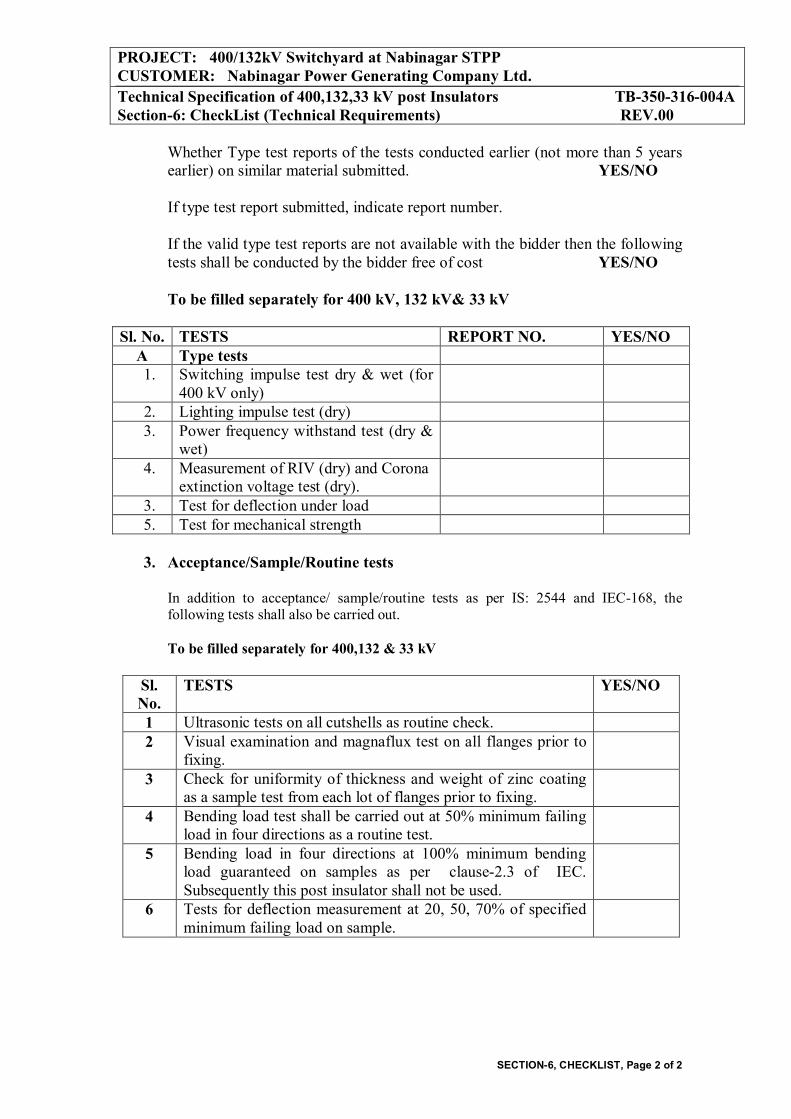
PROJECT: 400/132kV Switchyard at Nabinagar STPP CUSTOMER: Nabinagar Power Generating Company Ltd. Technical Specification of 400,132,33 kV post Insulators TB-350-316-004A Section-6: CheckList (Technical Requirements) REV.00
SECTION-6, CHECKLIST, Page 2 of 2
Whether Type test reports of the tests conducted earlier (not more than 5 years earlier) on similar material submitted. YES/NO If type test report submitted, indicate report number. If the valid type test reports are not available with the bidder then the following tests shall be conducted by the bidder free of cost YES/NO To be filled separately for 400 kV, 132 kV& 33 kV
Sl. No. TESTS REPORT NO. YES/NO
A Type tests 1. Switching impulse test dry & wet (for
400 kV only)
2. Lighting impulse test (dry) 3. Power frequency withstand test (dry &
wet)
4. Measurement of RIV (dry) and Corona extinction voltage test (dry).
3. Test for deflection under load 5. Test for mechanical strength
3. Acceptance/Sample/Routine tests
In addition to acceptance/ sample/routine tests as per IS: 2544 and IEC-168, the following tests shall also be carried out. To be filled separately for 400,132 & 33 kV
Sl. No.
TESTS YES/NO
1 Ultrasonic tests on all cutshells as routine check. 2 Visual examination and magnaflux test on all flanges prior to
fixing.
3 Check for uniformity of thickness and weight of zinc coating as a sample test from each lot of flanges prior to fixing.
4 Bending load test shall be carried out at 50% minimum failing load in four directions as a routine test.
5 Bending load in four directions at 100% minimum bending load guaranteed on samples as per clause-2.3 of IEC. Subsequently this post insulator shall not be used.
6 Tests for deflection measurement at 20, 50, 70% of specified minimum failing load on sample.