
N94-33829 - NASA · N94-33829 The Importance of Robust Error Control in Data Compression...
20
N94- 33829 The Importance of Robust Error Control in Data Compression Applications S.I.Woolley Dept. Electrical Engineering University of Manchester Oxford Road, MI3 9PL, U.K. Phone: 061-275-4538 Fax: 061-257-3902 san dra@h pc. ee. man. ac. uk Abstract Data compression has become an increasingly popular option as advances in information technology have placed further demands on data storage capacities. With compression ratios as high as I00:I the benefits are clear, however; the inherent intolerance of many compression formats to error events should be given careful consideration. If we consider that efficiently compressed data will ideally contain no redundancy, then the introduction of a channel error must result in a change of understanding from that of the original source. Whilst the prefix property of codes such as Huffman enables resynchronisation, this is not sufficient to arrest propagating errors in an adaptive environment. Arithmetic, Lempel-Ziv, discrete cosine transform (DCT) and fractal methods are similarly prone to error propagating behaviours. It is, therefore, essential that compression implementations provide sufficient combatant error control in order to maintain data integrity. Ideally, this control should be derived from a full understanding of the prevailing error mechanisms and their interaction with both the system configuration and the compression schemes in use. Introduction Data compression is essentially the process of identifying and extracting source redundancy in order to reduce storage requirements. Since the nature of encountered redundancy is dependent upon the type of source, e.g. image, audio, video, text, program source, database, instrumentation, etc., the best compression performance is achieved by a source-specific algorithm. For example, an image source may contain a large amount of positional redundancy (e.g. a raster scan of a vertical line) which could be efficiently exploited. However, an algorithm of this type would be of little benefit if applied to a textual source. Accordingly, each of the main source categories have their own families of compression algorithms. The following text provides an introduction to some important compression concepts, methodologies and behaviours, with the aim of demonstrating the effects of compression on data integrity and the need for adequate error control. Where possible, examples have been used to illustrate this information such that a prior understanding of compression methods and behaviours is not required. Advantages and Disadvantages of Data Compression ,_e__ PAGE BL.ANK NOT F'ILke_:_(._ 487 https://ntrs.nasa.gov/search.jsp?R=19940029323 2018-07-13T16:24:45+00:00Z
Transcript of N94-33829 - NASA · N94-33829 The Importance of Robust Error Control in Data Compression...

N94- 33829
The Importance of Robust Error Control in Data Compression
Applications
S.I.Woolley
Dept. Electrical EngineeringUniversity of Manchester
Oxford Road, MI3 9PL, U.K.
Phone: 061-275-4538Fax: 061-257-3902
san dra@h pc. ee. man. ac. u k
Abstract
Data compression has become an increasingly popular option as advances in information
technology have placed further demands on data storage capacities. With compression ratios
as high as I00:I the benefits are clear, however; the inherent intolerance of many compression
formats to error events should be given careful consideration.
If we consider that efficiently compressed data will ideally contain no redundancy, then the
introduction of a channel error must result in a change of understanding from that of the
original source. Whilst the prefix property of codes such as Huffman enables
resynchronisation, this is not sufficient to arrest propagating errors in an adaptiveenvironment. Arithmetic, Lempel-Ziv, discrete cosine transform (DCT) and fractal methods
are similarly prone to error propagating behaviours. It is, therefore, essential that
compression implementations provide sufficient combatant error control in order to maintain
data integrity. Ideally, this control should be derived from a full understanding of the
prevailing error mechanisms and their interaction with both the system configuration and thecompression schemes in use.
Introduction
Data compression is essentially the process of identifying and extracting source redundancy inorder to reduce storage requirements. Since the nature of encountered redundancy is dependent
upon the type of source, e.g. image, audio, video, text, program source, database,
instrumentation, etc., the best compression performance is achieved by a source-specific
algorithm. For example, an image source may contain a large amount of positional
redundancy (e.g. a raster scan of a vertical line) which could be efficiently exploited. However,
an algorithm of this type would be of little benefit if applied to a textual source. Accordingly,
each of the main source categories have their own families of compression algorithms.
The following text provides an introduction to some important compression concepts,
methodologies and behaviours, with the aim of demonstrating the effects of compression on
data integrity and the need for adequate error control. Where possible, examples have beenused to illustrate this information such that a prior understanding of compression methods
and behaviours is not required.
Advantages and Disadvantages of Data Compression
,_e__ PAGE BL.ANK NOT F'ILke_:_(._
487
https://ntrs.nasa.gov/search.jsp?R=19940029323 2018-07-13T16:24:45+00:00Z
In addition to the increasein data storagecapacity, real-time compressionimplementationscan enhancedata transferrates, improve network performanceby reducing traffic loads onlines and, via the encryptionprocess,provideadditional data security against unauthorisedaccess[I].
Thereare, however,disadvantagesinvolvedin datacompression.Firstly, the compresseddatais significantly more vulnerable to error, as will bedemonstrated below. Secondly, themajorityof softwarecompressorsdo not work in real-timesuch that data retrieval and storagecan be significantly delayed. This is particularly noticeablewith most imagecompressionmethods,althoughthedelayis,ofcourse,dependentonsystemperformanceand source size. Inaddition, the plethora of algorithms currently available can result in compatibility problems
when transferring data between systems. For example, the absence of an early compression
standard for DAT (Digital Audio Tape) drives resulted in two competing and incompatibleimplementations, such that compressed DAT tapes cannot be freely transferred between
systems which would otherwise be. compatible [2]. Compatibility is also deteriorated, to some
extent, by the existence of a variety of patents which make bespoke compressors moreattractive.
Channel Errors and Data Integrity
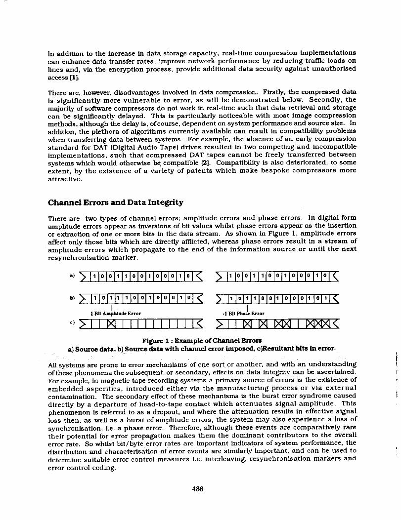
There are two types of channel errors; amplitude errors and phase errors. In dlgital form
amplitude errors appear as inversions of bit values whilst phase errors appear as the insertionor extraction of one or more bits in the data stream. As shown in Figure I, amplitude errors
affect only those bits which are directly afflicted, whereas phase errors result in a stream of
amplitude errors which propagate to the end of the information source or until the next
resynchronisation marker.
,!11olo11111olo111ololo111o1 11[°1°1111[°1°i11°[°i°[11°[
,,) 111°1111111°1'°111°1°1°111°1<I
1 Bit Amplitude Error
! ! II I 1 I ! I i
1 0 1 1 0 0 1 0 0 0 1 0 1
-1 Bit Pha_eI Error
Figure 1 : Example of Channel Errors
a) Source data, b) Source data with channel error imposed, c)Resultant bits in error.
All systems are prone to error mechanisms of one sort or another, and with an understanding
of these phenomena the subsequent, or secondary, effects on data integrity can be ascertained.
For example, in magnetic tape recording systems a primary source of errors is the existence of
embedded asperities, introduced either via the manufacturing process or via externalcontamination. The secondary effect of these mechanisms is the burst error syndrome caused
directly by a departure of head-to-tape contact which attenuates signal amplitude. This
phenomenon is referred to as a dropout, and where the attenuation results in effective signalloss then, as well as a burst of amplitude errors, the system may also experience a loss of
synchronisation, i.e. a phase error. Therefore, although these events are comparatively rare
their potential for error propagation makes them the dominant contributors to the overallerror rate. So whilst bit/byte error rates are important indicators of system performance, thedistribution and characterisation of error events are similarly important, and can be used to
determine suitable error control measures i.e. interleaving, resynchronisation markers and
error control coding.
488
Lossy and Lossless Compression Techniques
The amount of compression that can be achieved by a given algorithm depends on both the
amount of redundancy in the source and the efficiency of Its extraction. The very high
compression ratios often quoted generally relate to hlgh-redundancy sources such as databases
or to lossy compressed formats such as fractal image representations.
Lossless techniques are, of course, required by many applications, such as computer disk
compression, where exact replication of the original is essential. Alternatively, lossy
compression techniques, where only a close approximation of the original is reconstructed,
can be successfully applied to many image, video and audio applications where losses outsidevisual/aural perception can be tolerated, and where the additional compression achieved is
highly desirable. For example, the philosophy behind the lossy DCT (Discrete Cosine
Transform) compression of images is that the human eye is less sensitive to high-frequency
information. Further compression can, therefore, be achieved by more coarsely quantising
hlgh-frequency components of an image without significant visual deterioration.
There are, however, some image compression applications where certain quality and/or legal
considerations dictate the use of lossless compression. For example, medical imaging [3] and
deep space communication of imagery data [4].
Static and Adaptive Implementations
Compression algorithms remove source redundancy by using some working definition of thesource characteristics, i.e. a source model. Compression algorithms which use a pre-deflnedsource model are referred to as static, whilst algorithms which use the data Itself to fully orpartially define this model are referred to as adaptive.
Static implementations can achieve very good compression ratios for well defined sources;however, their inability to respond to changes in source statistics limits their usage. If appliedto a source significantly different from that modelled, a static aigorithm could result In sourceexpansion rather than compression.
In contrast, adaptive algorithms are more versatile, and will update their working sourcemodel according to current source characteristics. However, adaptive implementations havelowered compression performance, at least until a suitable model Is properly generated. Inaddition,
"A major problem with any adaptive compression method Is that a single error on thecommunlcatlon channel or storage medium can cause the sender and recelver to losesynchronisation and can result in error propagation that In the worst case can corrupt all datato follo w. "[5l
Compression Methodologies
The following text presents a selection of commonly used compression methods and
investigates the effects of channel errors on data integrity. Image sources and bit error mapsare used to illustrate these phenomena since the effects of any errors are more readily
appreciated.
489
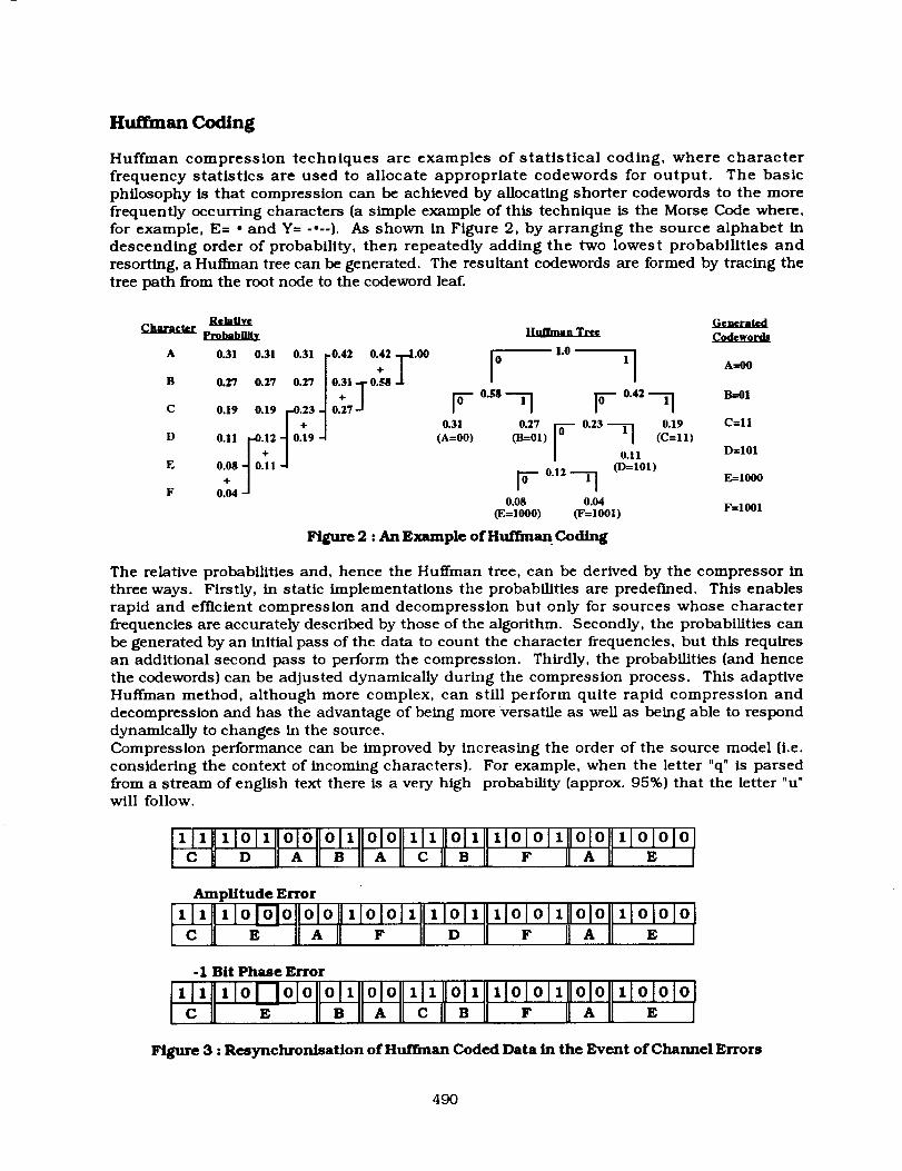
Hu_man Coding
Huffman compression techniques are examples of statistical coding, where character
frequency statistics are used to allocate appropriate codewords for output. The basic
philosophy is that compression can be achieved by allocating shorter codewords to the more
frequently occurring characters (a simple example of this technique is the Morse Code where,
for example, E= * and Y ..... ). As shown in Figure 2, by arranging the source alphabet in
descending order of probability, then repeatedly adding the two lowest probabilities and
resorting, a Huffman tree can be generated. The resultant codewords are formed by tracing the
tree path from the root node to the codeword leaf.
_Atext Ge_rat_V_harat_ _ _ Codewe_
A 03,03,03,¢,,. i0 ,0 'IB 0.27 0.27 0.27 0._8-J.
-- I o,1 0.9 c.o O.llr.,,lo.,, ,A--OO,F ,C-ll,]05 0.,, ._-,0,E 07 1 -4 (D=101)
F 0.04 F 0"12 "--T] E=1000
0.08 0.04(E=1000) (F=I001) F=1001
Figure 2 : An Example of Huffman Coding
The relative probabilities and, hence the Huffman tree, can be derived by the compressor in
three ways. Firstly, in static implementations the probabilities are predeflned. This enables
rapid and efficient compression and decompression but only for sources whose character
frequencies are accurately described by those of the algorithm. Secondly, the probabilities can
be generated by an initial pass of the data to count the character frequencies, but this requires
an additional second pass to perform the compression. Thirdly, the probabilities (and hence
the codewords) can be adjusted dynamically during the compression process. This adaptive
Huffman method, although more complex, can still perform quite rapid compression and
decompression and has the advantage of being more versatile as well as being able to respond
dynamically to changes in the source.
Compression performance can be improved by increasing the order of the source model (i.e.
considering the context of incoming characters). For example, when the letter "q" is parsed
from a stream of english text there is a very high probability (approx. 95%) that the letter "u"will follow.
I111 IIx Io1111olollol xllolol1111 Ilol 1111101o1111o101111olololIcll D IIAIIBI[AIIcIIBII F HAll E I
Amplitude Error
111 1101010 010 II0[0]I 11011 llO]O]li 010 11010]0
C E A F D F A E
-I Bit Phase Error
111 xlol Iolo ol1 ol0 xlx 011 xlololllolo xlololoC E B A C B F A E
Figure 3 : Resynchronisation of H_an Coded Data in the Event of Channel Errors
49O
There is, therefore, no single Huffman method, but rather a whole family varying in adaptlvltyand order[6]. The specific effects of any transmission errors on Huffman compressed data
would therefore depend on the particular implementation as well as the source. Fortunately,
however, some generalisations can be made. Firstly, static implementations have an in-built
resistance to error propagation. This is due to the prefix property common to all Huffman
codes, whereby no code is a prefix of any other. For example, using the generated codewords in
Figure 1, frO0 is a permitted codeword then no other codeword may begin with the sequence 00,
similarly if I01 is a permitted codeword then no other codeword may begin with the sequence
101, and so on. Figure 3 illustrates the effects of an amplitude and a phase error, demonstratingthe code's self-synchronising ability.
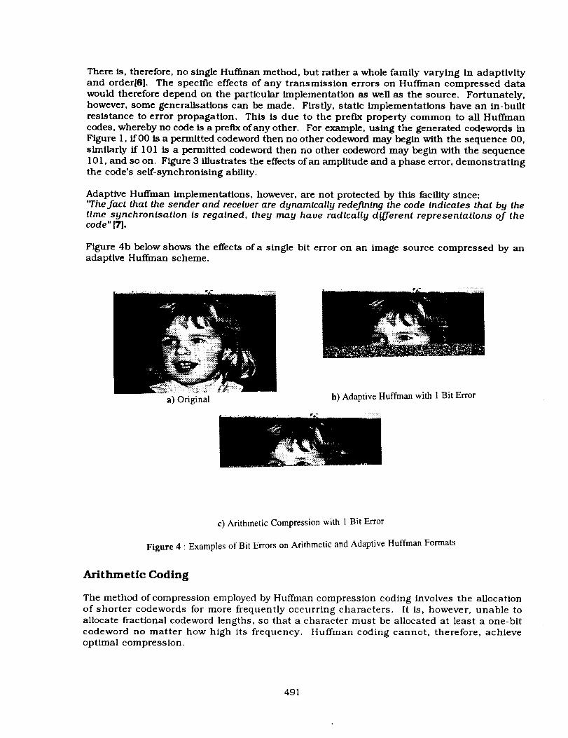
Adaptive Huffman implementations, however, are not protected by this facility since;"The fact that the sender and recelver are dynamlcally redeflnlng the code Indlcates that by thetlme synchrontsatlon Is regalned, they may have radlcally different representatlons of thecode" [7].
Figure 4b below shows the effects of a single bit error on an image source compressed by anadaptive Huffman scheme.
i ¸ ?i_ _
a) Original b) Adaptive Huffman with 1 Bit Error
c) Arithmetic Compression with 1 Bit Error
Figure 4 • Examples of Bit Errors on Arithmetic and Adaptive Huffman Formats
Arithmetic Coding
The method of compression employed by Huffman compression coding involves the allocation
of shorter codewords for more frequently occurring characters. It is, however, unable to
allocate fractional codeword lengths, so that a character must be allocated at least a one-bit
codeword no matter how high its frequency. Huffman coding cannot, therefore, achieve
optimal compression.
491
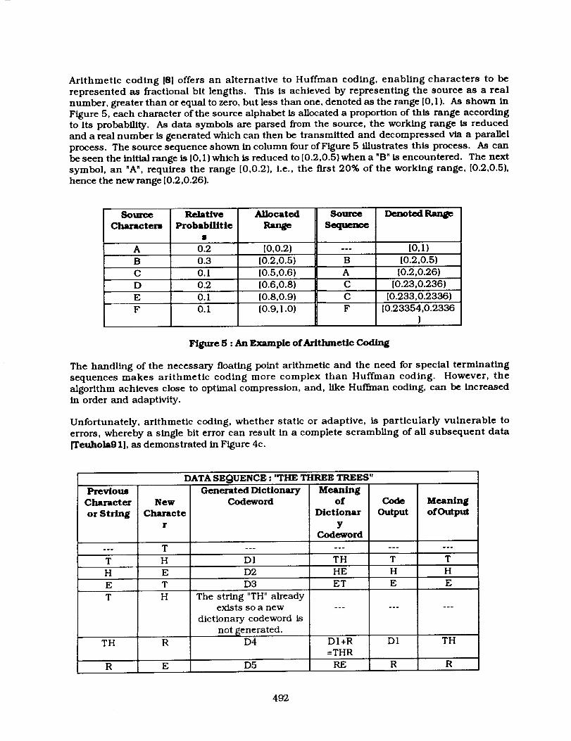
Arithmetic coding [8] offers an alternative to Huffman coding, enabling characters to be
represented as fractional bit lengths. This is achieved by representing the source as a real
number, greater than or equal to zero, but less than one, denoted as the range [0,1). As shown in
Figure 5, each character of the source alphabet is allocated a proportion of this range accordingto its probability. As data symbols are parsed from the source, the working range is reduced
and a real number is generated which can then be transmitted and decompressed via a paranel
process. The source sequence shown in column four of Figure 5 illustrates this process. As can
be seen the initial range is [0, I ) which is reduced to [0.2,0.5) when a "B" is encountered. The next
symbol, an "A", requires the range [0,0.2), i.e., the first 20% of the working range, [0.2,0.5),
hence the new range [0.2,0.26).
Source RelaUve Allocated Source Denoted Range
Characters Probabil/tie Range Sequence
A 0.2 [0,0.2) --- [0,1)
B 0.3 [0.2,0.5) B [0.2,0.5)
C 0. I [0.5,0.6) A [0.2,0.26)
D 0.2 [0.6,0.8) C [0.23,0.236)
E 0. I [0.8,0.9) C [0.233,0.2336)
F 0.1 [0.9,1.0) F [0.23354,0.2336)
Figure 5 : An Example ofAr/thmeUc Cod/ng
The handling of the necessary floating point arithmetic and the need for special terminating
sequences makes arithmetic coding more complex than Huffman coding. However, the
algorithm achieves close to optimal compression, and, like Huffman coding, can be increased
in order and adaptlvity.
Unfortunately, arithmetic coding, whether static or adaptive, is particularly vulnerable to
errors, whereby a single bit error can result in a complete scrambling of all subsequent data
[Teuhola91], as demonstrated in Figure 4c.
DATA SEQUENCE : "rile THREE TREES"
Prev/ous
Character
or String
T
H
E
T
TH
R
New
Characte
r
T
H
E
T
H
R
E
Generated DictionaryCodeword
Di
D2
D3
The string "TH" alreadyexists so fl new
dictionary codeword is
not _enerated.D4
D5
Meaningof
Dictionar
YCodeword
TH
HE
ET
DI+R
=THR
RE
Code
Output
T
H
E
R
Meaning
of Output
T
H
E
TH
R
472
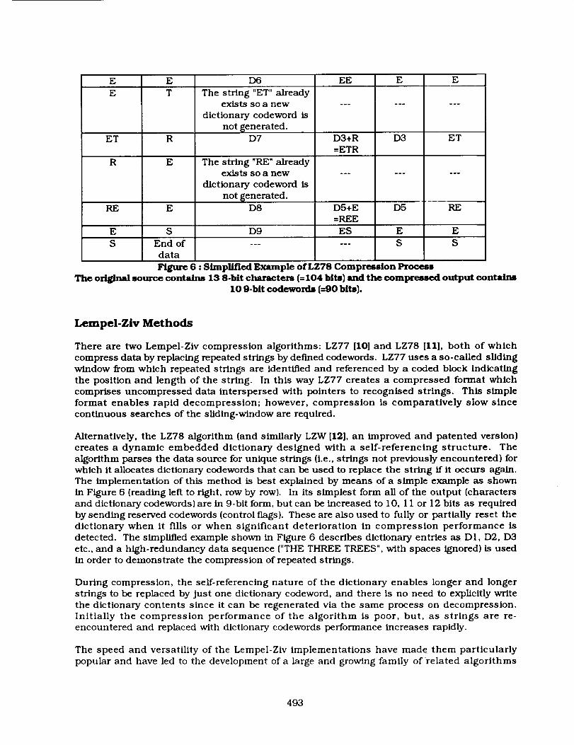
E E 156 EE E EE T
ET
R
RE
R
E
Thestring "ET"alreadyexistssoa new
dictionary codewordisnot _enerated.
D7
Thestring "RE"alreadyexistssoa new
dictionary codewordisnot{_enerated.
D3+R=ETR
D3 ET
E D8 D5+E
=REE
D5 RE
E S D9 ES E E
S End of ...... S S
data
Figure 6 : Simplified Example of LZ78 Compression Process
The original source conta/ns 13 8-bit characters (=104 bits) and the compressed output contains10 9-bit codewords (=90 bits).
Lempel-Ziv Methods
There are two Lempel-Ziv compression algorithms: LZ77 [10] and LZ78 [II], both of which
compress data by replacing repeated strings by defined codewords. LZ77 uses a so-called sliding
window from which repeated strings are identified and referenced by a coOed block Indicating
the position and length of the string. In this way LZ77 creates a compressed format which
comprises uncompressed data interspersed with pointers to recognised strings. This simple
format enables rapid decompression; however, compression is comparatively slow since
continuous searches of the sliding-window are required.
Alternatively, the LZ78 algorithm (and similarly LZW [12], an improved and patented version)
creates a dynamic embedded dictionary designed with a self-referencing structure. The
algorithm parses the data source for unique strings (i.e., strings not previously encountered) for
which it allocates dictionary codewords that can be used to replace the string ff it occurs again.The implementation of this method is best explained by means of a simple example as shown
in Figure 6 [reading left to right, row by row). In its simplest form all of the output (charactersand dictionary cooewords) are in 9-bit form, but can be increased to 10, 11 or 12 bits as required
by sending reserved codewords (control flags). These are also used to fully or partially reset the
dictionary when it fills or when significant deterioration in compression performance is
detected. The simplified example shown in Figure 6 describes dictionary entries as DI, D2, D3
etc., and a high-redundancy data sequence ("THE THREE TREES", with spaces ignored) is usedin order to demonstrate the compression of repeated strings.
During compression, the serf-referencing nature of the dictionary enables longer and longer
strings to be replaced by just one dictionary codeword, and there is no need to explicitly write
the dictionary contents since it can be regenerated via the same process on decompression.
Initially the compression performance of the algorithm is poor, but, as strings are re-encountered and replaced with dictionary codewords performance increases rapidly.
The speed and versatility of the Lempel-Ziv implementations have made them particularly
popular and have led to the development of a large and growing family of related algorithms
493
([13]refers to 12 variants of Lempel-Ziv methods). Implementations of Lempel-Ziv type
algorithms can be found in most computer disk compressors and on tape drives including DAT.
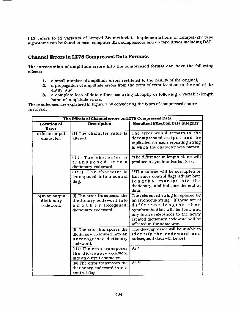
Channel Errors in LZ78 Compressed Data Formats
The introduction of amplitude errors into the compressed format can have the following
effects:
1, a small number of amplitude errors restricted to the locality of the original,
2. a propagation of amplitude errors from the point of error location to the end of the
entity, and
3, a complete loss of data either occurring abruptly or following a variable-length
burst of amplitude errors.
These outcomes are explained in Figure 7 by considering the types of compressed sourceinvolved.
The Effects of Channel errors on LZ78
Location of DescriptionError
a) In an outputcharacter.
b) In an output
dictionarycodeword.
Compressed Data
(i) The character value isaltered.
(il) The character is
transposed into a
dictionary codeword.
(iii) The character is
transposed into a control
flag.
(i) The error transposes the
dictionary codeword into
a n o t h e r [recognised]
dictionary codeword.
(ii) The error transposes the
dictionary codeword into an
unrecognised dictionarycodeword.
(iii) The error transposes
the dictionary codeword
into an output character.
(iv) The error transposes the
dictionary codeword into a
control flag.
Resultant Effect on Data Integrity
The error would remain in the
decompressed output and be
replicated for each repeating stringin which the character was parsed.
*The difference in length alone will
produce a synchronisation loss.
**The source will be corrupted or
lost since control flags adjust byte
lengths, manipulate the
dictionary, and indicate the end ofdata.
The referenced string is replaced by
an erroneous string. If these are ofdifferent lengths then
synchronisation will be lost, and
any future references to the newly
created dictionary codeword will be
affected in the same way.
The decompressor will be unable toidentify the codeword and
subsequent data will be lost.
As*
As _
494
c) In a controlflag.
(i)The control flag ismistaken for an output
character or a dictionarycodeword.
AS _
Figure 7 : A Description of the Potential Effects of Channel Errors on an LZ78 CompressedSource.
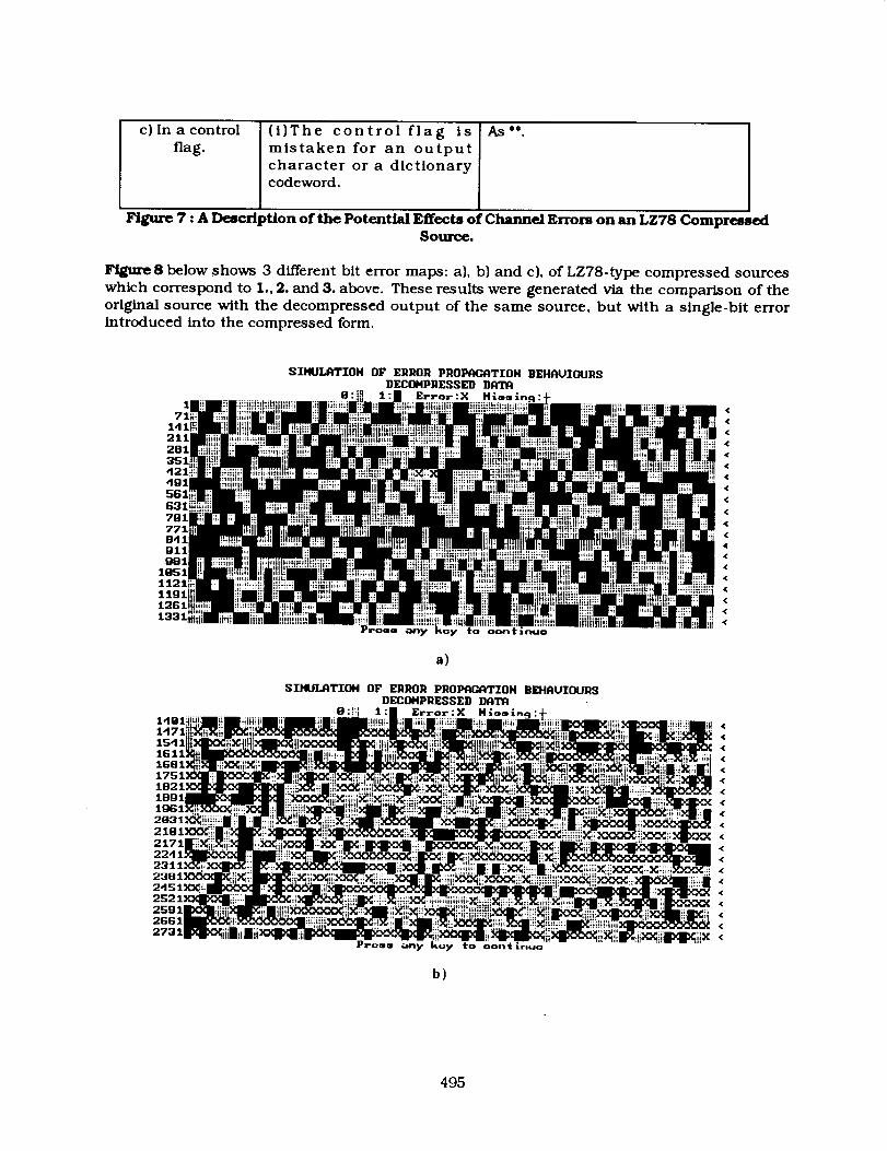
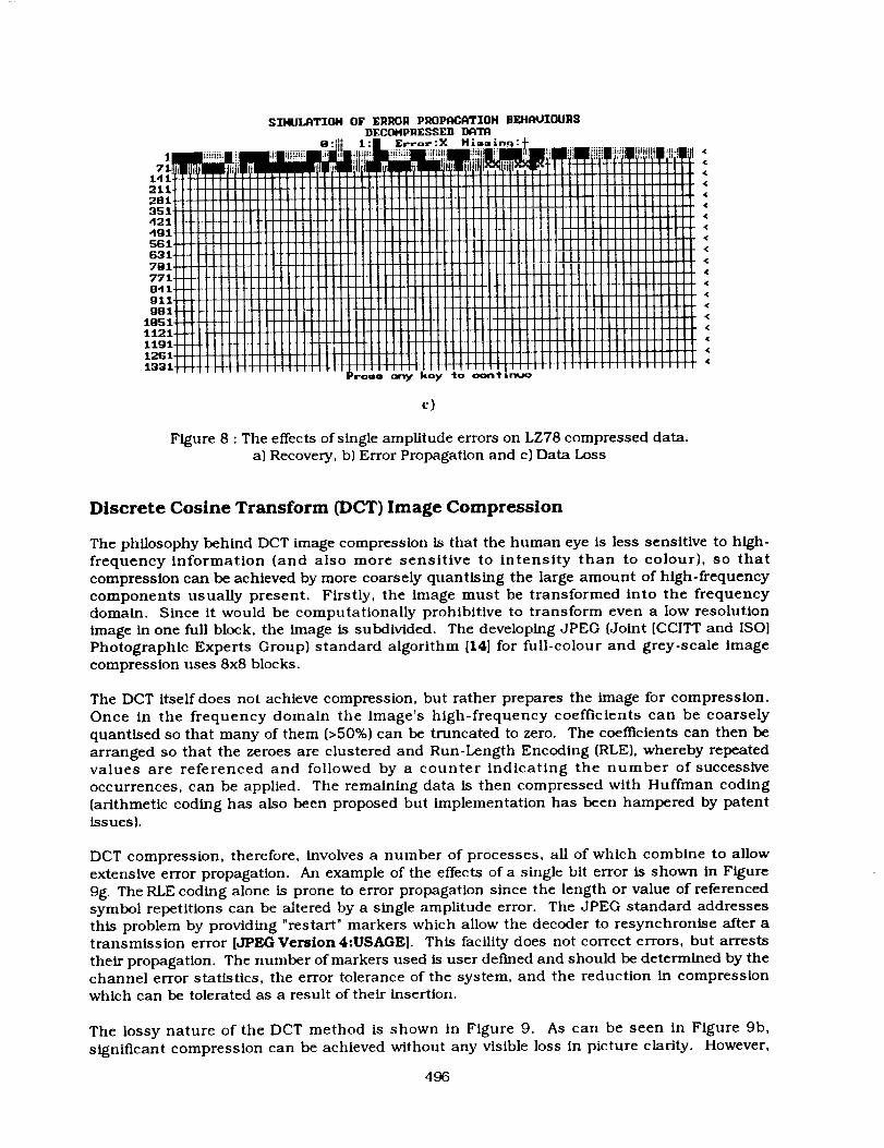
Figure8 below shows 3 different bit error maps: a), b) and c), of LZ78-type compressed sources
which correspond to 1., 2. and 3. above. These results were generated via the comparison of the
original source with the decompressed output of the same source, but with a single-bit errorintroduced into the compressed form.
211281
351
dgl
G31i
B41
gllg81
lg511121
.¢
,¢
<,¢,¢
<
<
,¢
<
<
,(
a)
SIHUI_TII_I OF ERROR PROPI_-_ITIOH BEHAUIOURS
DECOHPRF_SEB DATA
8:_T_ 1:| Error:X Hiamin 9 -it-1491 m ,_ _m _ • m m m "i i =tiiiii
1611 _, ;,i •1681 •
•: I! I _q ' | •
. _ii_iiixx_._i:"c_:x_iii_iiiiiiii!iiiii[x:xx_i;;x:_ill ....... i;iiiil •2451_ •
2S21 •2Sgl •
2731.2661" ,. iiii__iii__<"iii i "' !!!i!i!i iiiX_!iii!!!_i: ..... _ •
rro¢_l o_1_ I_oy TO oon(in_o
b)
495
SII4UI_TIOH OF ERROR PROI_flTIOH BEHflL_OURSDECOHPRESSED l_flTn
B:II;] 1:| E .... :x M_ui-9:_til .......... _ " ; "' ' _ .... _ , ;: : L ' _ 'fit+ 'i+ ill ti_ tl' il_i[_ tilt'_i I
21.1t l[ i i i i i IT[_]_ _]111111 III IIl11111Jlll III III I IIIIIIIJ_L_i I u]liM_ Ll]u]i,iiliJllrrrliJliillil,,,,,,,281LJ ' ' ' ' ' ' ' I ' ' ' '_[JLLLIJ[I-35111' ' l II , , , , , , , ,TI , , ,, ,, _]]_LLLL uzLuzINtIill III IIIII I IIIII IIIIII
_it _iilllitil//lllllll II1111111 IIIIIII1 II•12i 1111-111_.lfl-itttttilll]llt"illi'llliiiii/lltt_ /illlllll llillllll'L]__]lll i 1 IIIIIIIli
Ht t "f,,"',. ,,,L,,,,, <e41TR_rlIIILL_/I 111111111 III]TRT[_TRIIIIIIIIJlIIIIIIIII •lil.lllllllllll[_qTF_T_ll II[J]llll IIIII._ITT_IilI[IHIIIIIIIIIIIIII •_',_lHi]_lli_llllllll II " /ll/IIIIIIIIIIIIU <g"it-H-_tlili i i i I I I-_t _l_-H-t ILHI i ,il i I I I I,, , , , , ,1, <
l°S 11-tttt-ft-1-1111 _1 l]lllllll ] I 1FFIZI11 JJ_LLIJIUJ_[ I I I 1i I I 11 I I •t121 " <llill I •....11_l_H_HH _,1 I1LLI'IIH Jill 111 IIIJ.LIlII I I I I I II I II11 IIII •:I:t:t_I_LLi IHHI_]]]]liiI I-]IlIIHI III]ILI l TI-_IIIIIILIIIIIIIIII
__/IIIIIIILIIJ_LLI_[J._LLLII-I- I1111[11 JLU_LL II rrH l!IHllllllllllll I •.t. ilillllll iiiiii iiiiii iiii II IIII11/ l-HIll I/I I 1
l_oll _ ko_ to ooe"ltinuo
c)
Figure 8 : The effects of single amplitude errors on LZ78 compressed data.a) Recovery, b) Error Propagation and c) Data Loss
Discrete Cosine Transform (DCT) Image Compression
The philosophy behind DCT image compression is that the human eye is less sensitive to high-
frequency information (and also more sensitive to intensity than to colour), so thatcompression can be achieved by more coarsely quantising the large amount of high-frequency
components usually present. Firstly, the image must be transformed into the frequency
domain. Since it would be computationally prohibitive to transform even a low resolution
image in one full block, the image is subdivided. The developing JPEG (Joint [CCITT and ISO]
Photographic Experts Group) standard algorithm [14] for full-colour and grey-scale image
compression uses 8x8 blocks.
The DCT itself does not achieve compression, but rather prepares the image for compression.
Once in the frequency domain the image's high-frequency coefficients can be coarsely
quantised so that many of them (>50%) can be truncated to zero. The coefficients can then be
arranged so that the zeroes are clustered and Run-Length Encoding (RLE), whereby repeatedvalues are referenced and followed by a counter indicating the number of successive
occurrences, can be applied. The remaining data is then compressed with Huffman coding
(arithmetic coding has also been proposed but implementation has been hampered by patent
issues).
DCT compression, therefore, involves a number of processes, all of which combine to allow
extensive error propagation. An example of the effects of a single bit error is shown in Figure
9g. The RLE coding alone is prone to error propagation since the length or value of referencedsymbol repetitions can be altered by a single amplitude error. The JPEG standard addresses
this problem by providing "restart" markers which allow the decoder to resynchronise after atransmission error [JPEG Version 4:USAGE]. This facility does not correct errors, but arrests
their propagation. The number of markers used is user defined and should be determined by thechannel error statistics, the error tolerance of the system, and the reduction in compression
which can be tolerated as a result of their insertion.
The lossy nature of the DCT method is shown in Figure 9. As can be seen in Figure 9b,
significant compression can be achieved without any visible loss in picture clarity. However,
496

by increasing the compressionperformancefurther lossesare seen to develop (particularlylossyexampleswere chosensince the effectswere required to be visible after reduction forinclusion in this document).
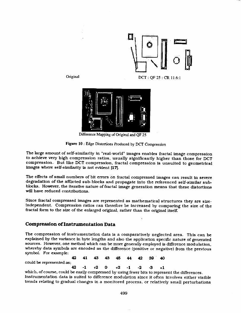
Thepresenceof artifacts aroundsharpedgesis referredto as Glbb'sphenomenon1151(pg225).Theseare causedby the inability of a finite combinationof continuous functions to describeJumpdiscontinuities. Asshownin Figure9e,at highercompressionratios these lossesbecomemoresapparent, as does the blocked nature of the compressedform. Figure 9f shows adifferencemappingof the original and the highly lossydecompressedimagein which the lossof edgeclarity canbeobserved.
This type of lossyness makesJPEGand other DCT-basedalgorithms unsuitable for non-realistic images,e.g. line drawings, cartoons, etc., as can be seen by the large amount ofdeteriorationin the geometricexampleusedin Figure i0.
Fractal Image Compression
A fractal, in simplest terms, is an image of a texture or shape expressed as one or more
mathematical formulae. It is a geometric form whose irregular details recur at different
locations, scales and angles, and which can be described in terms of formulae called affine or
fractal transformations [16]. Fractal image compression is achieved by dividing an image intosub-blocks, each of which is then compared to scaled and rotated versions of the other sub-
blocks in the image. When sufficiently similar sub-blocks have been found for all of the sub-
blocks in the image, they can be referenced geometrically so that a fractal description isobtained.
Unlike other image compression techniques, the fractal transform is a very asymmetric
process. The exhaustive searching for self-similarity requires intensive computational power,
but once expressed in terms of fractal transforms the image can be quickly decompressed.
Fractal compression is therefore best suited to WORM applications. For example, the Microsoftmultimedia encyclopaedia Encarta makes use of fractal compression to store hundreds of
colour maps and thousands of photographs on a single CD which also contains extensive audio,animation and textual data. [15].
497

a)Original b) DCT:QF3:CR8:I
¢)DCT: QF10: CR11.6:1
e)DCT: QF25: CR14.2:1
d)DCT:QF20 :CR13.6:1
f)DifferenceMappingofOriginalandQF25
g)DC;P(8:1)wiih lBitError
Figure 9: b)-e) DCT Compressed Images of a) : QF (Quality Factor) in the range [1-25] (best-worst)f) Comparison of a) and e)
g) Data Loss due to a Single Bit Error
498
Original
°li,,
DCT:QF25:CR I1.6:1
Difference Mapping of Original and QF 25
Figure 10 : Edge Distortions Produced by DCT Compression
The large amount of self-similarity in "real-world" images enables fractal image compression
to achieve very high compression ratios, usually significantly higher than those for DCT
compression. But like DCT compression, fractal compression is unsuited to geometricalimages where self-similarity is not evident [17].
The effects of small numbers of bit errors _3n fractal compressed images can result in severedegradation of the afflicted sub-blocks and propagate into the referenced self-similar sub-
blocks. However, the Iterative nature of fractal image generation means that these distortionswill have reduced contributions.
Since fractal compressed images are represented as mathematical structures they are size-
independent, Compression ratios can therefore be increased by comparing the size of thefractal form to the size of the enlarged original, rather than the original itself.
Compression oflnstrumentation Data
The compression of instrumentation data is a comparatively neglected area. This can be
explained by the variance in byte lengths and also the application specific nature of generatedsources. However, one method which can be more generally employed is difference modulation,
whereby data symbols are encoded as the difference (positive or negative) f_om the previoussymbol. For example:
42 41 43 43 45 44 42 39 40
could be represented as;42 - I +2 0 +2 - 1 -2 -3 + I
which, of course, could be easily compressed by using fewer bits to represent the differences.Instrumentation data is suited to difference modulation since it often involves either visible
trends relating to gradual changes in a monitored process, or relatively small perturbations
499
centredaboutsomemeanvalue. Differencemodulation is also useful in audio compressionapplications, wheretrends can be identified in the source waveform. In applications werelossescan be tolerated,the quantisationof differencescanachievefurther compression.In thepresenceof channel errors differencemodulationwill result in error propagationsinceeachof the symbolsmeasuresitselfagainstits predecessor.Theresultant shift causedby a biterrorwill bereplicatedin all subsequentsymbolsondecompression,propagatinguntil the endofthe datasequenceoruntil thenext true measurementis parsed.
Conclusion
In the absence of data compression many systems, when afflicted by uncorrected channel
errors, will suffer only localised losses in data integrity, i.e. will fail gracefully.. However,
similar errors in systems using data compression can have disastrous results. For this reason
users of computer disk compression are advised to take regular backups since: "if something
does go wrong, it is llkely to be major".[18].
The results of transmission errors on different compression methodologies has been
demonstrated, and the need for robust error control emphasised. This control should be
determined by the channel error statistics and the error tolerance of the system. In addition to
error control coding, piece-wise compression, resynchronisation markers and deep
interleaving can also be employed to limit the propagation of errors and reduce the correction
burden placed on the error control coding.
Acknowledgements
Much of the work presented here was sponsored by British Gas Plc, whose financial and
technical support has been greatly appreciated. I am also very grateful for the interest and
support given by IC! Imagedata which has enabled the publication of this work. Finally, Iwould llke to thank to my research supervisor, Prof.B.K.Middleton, and Dr.B.Bani-Eqbal (Dept.
Computer Science, University of Manchester) for his technical advice on fractal and DCT
compression implementations.
References
[1] The Hidden Benefits of Data Compression
D.Powell
Networking Management, Vol.7, No. I0, October 1989, pp46-54
[2] The Compression WarsJ.McLeod
Electronics, Voi.64, September 9 I, pp27-28
[31 Performance Analysis of Reversible Image Compression Techniques
for High-Resolution Digital Teleradiology
G.R.Kuduvalli and R.M.RangayyanIEEE Transactions on Medical Imaging, Vol. I I, No.3, September
1992, pp430-445
500
[4]
[5]
[8[
[7]
[8]
[9]
[10]
[11]
[12]
[13]
[14]
[15]
[16]
Recent Advances in Lo_less Coding TechnlquesG.S .Yovanof
Proc-27th Int. Telemetric Conf. ITC91, pp7-19
Data CompressionA.Booksteln and J.A.Storer
Information Processing and Management, Vol 28, No.6, 1992, pp675-680
Overview of Huffman Encoding as [a] Compression TechniqueK.Anderson
Computer Technology Review, Vol. I I, No.6, 199 I, pp97- I 01
Data Compression
D.A.Lelewer and D.S.Hirschberg
ACM Computing Surveys, Vol. 19, No.3, September 1987, pp261-296
An Introduction to Aritlunetic Coding
G.G.LangdonIBM Journal of Research and Development, Voi.28, No.2, March
1984, pp135-149
Piecewise Arithmetic CodingJ.Leuhola and T.Ralta
Proceedings of DCC'91, pp33-42
A Un/versal Algorithm for Sequential Data Compression
J.Ziv and A.LempelIEEE Trans IT, IT-32, No.3,May 1977,pp337-343
Compression of Individual Sequences via Variable-Rate Coding
J.Ziv and A.Lempel
IEEE Trans IT, IT-24, No.5,Sept 1978, pp530-536
A Technique for High-Performance Data CompressionT.A.Welch
IEEE Computer, Vol. 17, No.6, June 1984, ppS- 19
Text CompressionT.C.Ben, J.G.Cleary and I.H.Witten
Published by Prentice Hall, Englewood Cliffs,NJ. 1990
The JPEG Still Picture Compression StandardG.K.WaUace
Communications of the ACM, Voi.34, No.4, April 1991, pp31-44
Fractal Image Compression
M.F.Barnsley and L.P.Hurd
Published by AK Peters Ltd, 1993, ISBN 1-56881-000-8
Advances in Digital Image Compression TechniquesG .Lu
Computer Communications, Vol 16, NO.4, April 1993, pp202-214
501
[17]
[18]
Fractals Transform Image Compression
A.WrightElectronics World and Wireless World, March 1992, pp208-211
Data Compression SoftwareR. Milton
Computing, 22 July 1993, pp19-20
502

Form Approved
REPORT DOCUMENTATION PAGE OMBNo. 0704-0188
Public reportingburden for this co act on of information is estimated to average 1 hourper response, includingthe time for reviewing instructiOnS, searching existingdata sources,gathering and ma ntein ng he data needed, and completing end reviewingthe collectionof information. Send comments regardingthis burden estimate or any other aspect of thiscoflectionof information, including suggestions for reducingthis burden, to Wash ngtoo Headquarters Servces, D rec orate for InformationOperations and Reports, 1215 JeffersonDavis Highway,Suite 1204, Arlington,VA 22202-4302, and to the Office of Management and Budget, Paperwork ReductionProject (0704-0188), Washington, DC 20503.
1. AGENCY USE ONLY (Leave b/ank) 2. REPORT DATE 3. REPORT TYPE AND DATES COVERED
April 1993 Conference Publication_ October 19-21 r 1993
4. TITLE AND SUBTITLE 5. FUNDING NUMBERS
Third NASA Goddard Conference on Mass Storage Systems and
Technologies
6. AUTHOR(S)
Benjamin Kobler and P. C. Hariharan, Editors
7. PERFORMING ORGANIZATION NAME(S) AND ADDRESS (ES)
Goddard Space Flight Center
Greenbelt, Maryland 20771
9. SPONSORING / MONITORING ADGENCY NAME(S) AND ADDRESS (ES)
National Aeronautics and Space Administration
Washington, DC 20546-0001
11. SUPPLEMENTARY NoTEs
Kobler: Goddard Space Flight Center, Greenbelt, Maryland;Hariharan: Systems Engineering and Security, Inc., Lanham, Maryland.
505
8. PEFORMING ORGANIZATION
REPORT NUMBER
12a. DISTRIBUTION / AVAILABILITY STATMENT
Unclassified - Unlimited
Subject Category 82
94B00057
10. SPONSORING I MONITORING
ADGENCY REPORT NUMBER
NASA CP-3262
12b. DISTRIBUTION CODE
13. ABSTRACT (Maximum 200 words)
This report contains copies of nearly all of the technical papers and viewgraphs presented at the
Goddard Conference on Mass Storage Systems and Technologies held in October 1993. Once again,
the conference served as an informational exchange forum for topics primarily relating to the ingestion
and management of massive amounts of data and the attendant problems involved. Discussion topics
include the necessary use of computers in the solution of today's infinitely complex problems, the need
for greatly increased storage densities in both optical and magnetic recording media, currently popular
storage media and magnetic media storage risk factors, data archiving standards including a talk on the
current status of the IEEE Storage Systems Reference Model (RM). Additional discussion topics
addressed System performance, data storage system concepts, communications technologies, data
distribution systems, and finally, a talk on data compression and error detection and correction.
14. SUBJECT TERMS
Magnetic tape, magnetic disk, optical disk, mass storage, software storage,digital recording, data compression
17. SECURITYCLASSIRCATION 18. SECURITYCLASSIRCATIONOFREPORT OFTHISPAGE
Unclassified Unclassified
NSN7540-01-280-5500
19. SECURITY CLASSIRCATIONOF ABSTRACT
Unclassified
15. NUMBER OF PAGES
51416. PRICE CODE
20. LIMITATION OF AB,_T_ACT
UL
Standard Form 298 (Rev. 2-89)Prescribed by ANSI Std. Z39.1B

= _
SA _ ......_- _NTER FOR AEROSPACE INFORMATION -- :_:_-?- - --
ACCESSIONING _-_.=- =_.=...... _ - -800 ELKRIDGE LANDING ROAD _ ....LINTNICUM HEIGHTS MO 210902934 .--


![II N94-33493 - NASA · ii n94-33493 high performance jet-engine flight ... w nch instruments & transmitter] ... 1171. flight ensemble averaging](https://static.fdocuments.in/doc/165x107/5bc3cd6509d3f299608d70f1/ii-n94-33493-nasa-ii-n94-33493-high-performance-jet-engine-flight-w-nch.jpg)
