N94-15581 - NASA Two Color Satellite Laser Ranging Upgrades ... The Quantel laser was replaced with...
13
N94-15581 Two Color Satellite Laser Ranging Upgrades At Goddard's 1.2m Telescope Facility Thomas W. Zagwodzki Jan F. McGarry John J. Degnan NASA/Goddard Space Flight Center Greenbelt, Maryland 20771 Thomas K. Varghese Bendix Field Engineering Corporation Seabrook, Maryland 20706 Abstract The ranging laboratory at Goddard's 1.2m telescope tracking facility has recently been upgraded to include a single photoelectron sensitive Hamamatsu streak camera-based range receiver which uses doubled and tripled Nd:YAG frequencies for satellite laser ranging. Other ranging system upgrades include a new Continuum laser, which will deliver up to 30 millijoules (mJ) at both 532 and 355 nm at a pulsewidth of 30 picoseconds (FWHM), and replacement of both ranging and tracking computers with COMPAQ 386 based systems. Preliminary results using a photomultiplier tube based receiver and waveform digitizer indicate agreement within the accuracy of the measurement with the theoretical Marini and Murray model for atmospheric refraction. Two color streak camera measurements will be used to further analyze the accuracy of these and other atmospheric refraction models. 7-15 https://ntrs.nasa.gov/search.jsp?R=19940011108 2018-07-13T17:04:20+00:00Z
Transcript of N94-15581 - NASA Two Color Satellite Laser Ranging Upgrades ... The Quantel laser was replaced with...
N94-15581
Two Color Satellite Laser Ranging Upgrades
At Goddard's 1.2m Telescope Facility
Thomas W. ZagwodzkiJan F. McGarryJohn J. Degnan
NASA/Goddard Space Flight CenterGreenbelt, Maryland 20771
Thomas K. Varghese
Bendix Field Engineering CorporationSeabrook, Maryland 20706
Abstract
The ranging laboratory at Goddard's 1.2m telescope trackingfacility has recently been upgraded to include a singlephotoelectron sensitive Hamamatsu streak camera-based rangereceiver which uses doubled and tripled Nd:YAG frequencies forsatellite laser ranging. Other ranging system upgrades include anew Continuum laser, which will deliver up to 30 millijoules (mJ)at both 532 and 355 nm at a pulsewidth of 30 picoseconds
(FWHM), and replacement of both ranging and tracking computerswith COMPAQ 386 based systems. Preliminary results using a
photomultiplier tube based receiver and waveform digitizerindicate agreement within the accuracy of the measurement withthe theoretical Marini and Murray model for atmospheric refraction.Two color streak camera measurements will be used to further
analyze the accuracy of these and other atmospheric refractionmodels.
7-15
https://ntrs.nasa.gov/search.jsp?R=19940011108 2018-07-13T17:04:20+00:00Z

INTRODUCTION
Satellite laser ranging efforts at the 1.2m tracking telescope at
Goddard's Geophysical and Astronomical Observatory (GGAO) have
evolved over the past few years in response to the demand for more
accurate SLR data. This includes a frequency-tripled Nd:YAG laser
system and a streak camera based range receiver. The laboratorywhich houses the Experimental Satellite Laser Ranging System
(ESLRS) adjoins a azimuth-elevation mount multi-user facility
designed to support the scientific community at the Goddard SpaceFlight Center. Two of six facility experimenter port locations arededicated to the laser transmitter and the streak camera based
receiver for ranging applications. The ESLRS is a ranging laboratory
where new instrumentation, hardware and software are investigated
and characterized for planning and developing next generationsystems. The SLR data gathered by the ESLRS is considered
engineering data and is not archived as is other NASA laser trackingnetwork data. The end users of the ESLRS data are the
experimenters and their goal is to use this information to better
understand system problems and to help transition laboratory
systems more efficiently to field SLR operations. Other system
upgrades include a new 386 based tracking computer, a new 386
based ranging computer, and physical plant upgrades at the facility.
The ESLRS has been operational since 1983 except for periods inwhich high priority flight programs within the Instrument Electro-
Optics Branch left the facility without crew support. The initialSLR system [McGarry et al, 1-986] included a Quantei YG 402 DP
frequency-doubled Nd:YAG laser, a two stage ITT F4128
microchannel plate photomultiplier tube (MCP-PMT), Ortec 934 and
later Tennelec TC 453 constant fraction discriminators (CFD's), and
a developmental time interval unit (TIU) built by Lawrence Berkeley
Laboratory. This system operated at a 5 hertz rate at the doubledYAG wavelength (532nm) and yielded data at the i to 2 centimeter
level on LAGEOS with a _Ve_ h_gh _retum:t0-fire _ ratiol
7-16

PROGRAM GOALS
Goddard Laser Tracking Network (GLTN) systems currently operating
at or below the 1 cm level RMS must still rely on models of
atmospheric range correction which assume certain altitude profiles
for temperature, pressure, and possible gradient effects. Knowledge
of atmospheric range correction on a shot-to-shot basis is therefore
uncertain, and must be addressed to eliminate atmospheric concerns.The best way of accounting for the atmospheric range correction is
to measure it on a shot-to-shot basis. The time of flight
measurement is made in the conventional manner with a MCP based
receiver using the 532nm pulse, while a differential time of flight
between the 532nm and 355nm pulses is made with a streak camera
based receiver. In making a streak camera differential measurement
accurate at the few picosecond level, the atmospheric range
correction can be recovered at the few millimeter level. Work in
improving ground-based SLR accuracies closely parallel work on
planned next generation space-based laser ranging systems. Effortsin the ranging laboratory at the 1.2m facility have been
concentrating on both programs in this parallel effort.
SYSTEM UPGRADES
The extension from single color to two color operation at the 1.2m
facility required significant system upgrades, one being an
improvement in low mirror reflectivities in the UV. Recoating of alltelescope mirror surfaces was required since previous coatingsrevealed mirror reflectivities in the UV of typically 50 to 60% and
one as low as 40%. For a 6 mirror coude focus system used in
common optics configuration, UV operation was prohibitive. Newaluminum mirror coatings with an SiOx overcoating (peaked at
355nm) improved surface reflectivities to typically 92% at 355nmand 88% at 532nm while maintaining broadband characteristics
required by other experimenters at the facility.
Return signal levels from LAGEOS are not adequate for two colorstreak camera-based operation with the present system. Therefore
we have opted to use low earth orbiting satellites such asSTARLETTE, AJISAI, and ERS-1 for two color data collection. As an
acquisition aid for sunlit passes, two TV camera systems have beenadded to the mount, and a third low light level RCA silicon
intensified target (SIT) camera has been used in the system prime
focus.
7-17
Facility upgrades include the replacement of the PDP 11/24 trackingcomputer with a COMPAQ 386/20 based system, and new
meteorological instruments including air pressure, temperature, and
relative humidity. The ranging computer, a LSI 11/23 (MINC), wasalso replaced with a COMPAQ 386/20 system.
Ranging instrumentation upgrades include both laser transmitter and
receiver. The laser available for use at the 1.2m facility for ranging
from 1983 to March of 1992 was a Quantel passively mode locked
Nd:YAG system model number YG402 DP. This laser system generated
up to 60 mJ of doubled YAG at 532nm and about 15 mJ of tripled YAGat 355 nm in a 140 picosecond pulse (FWHM). To make differential
measurements accurate at the picosecond level laser pulsewidths
must be narrowed considerably, and target satellites with low pulse
spreading must be used. The Quantel laser was replaced with a
Continuum model PY-62 YAG with doubling and tripling capability.The new Continuum laser outputs 30 picosecond pulses with about30 mJ of energy at both 532nm and 355nm. The laser fire rate is
currently 4 hertz, with work underway to increase it to 10 hertz.
The laser is housed in a clean room approximately 10 meters from
the base of the mount. The output beam is coupled into the telescope
system with a negative lens (negative focal length matching the F28
ray bundle of the 1.2m system) and a 45 degree aperture sharing'holey' mirror just inside the system focal plane. The outgoing laser
beam is translated approximately 1.25 cm from the optical axis ofthe telescope to avoid the shadowing by the central obscuration
(secondary mirror) in the telescope. The output beam is
approximately .4m in diameter, exits the system cleanly betweenthe primary and secondary mirror, and travels around that annulus as
the system tracks in azimuth. This configuration results in the
least amount of loss in the outgoing beam. In the common opticsmode the return path at the 45 degree mirror is folded across an NRC
table top to another mirror, Splitter, and receiver package. In theprime focus of the system is a field stop, to limit the receiver fieldof view, and a high speed shutter.
The receive signal is split between a two stage ITT model F4128
MCP PMT and a Hamamatsu streak camera. Shown in Figure 1 is asimplified block diagram of the system that was used for both
aircraft and Relay Mirror experiments as well as current SLR
activities. The streak camera in use up until the Spring of 1992 was
7-18

- 7-19
a 2 picosecond resolution Hamamatsu model 1370. This unit was
integrated into the system in support of two color experiments
which included both aircraft and the NASA/Air Force Relay MirrorExperiment (RME) programs. The signal threshold for the Hamamatsu
1370 streak camera is estimated at several thousand photoelectrons
and could be used only for ground work, aircraft, and the RME
program where signal levels were extremely high. The Hamamatsu
1370 streak camera has since been replaced with a newerHamamatsu model 2909 which has an additional internal
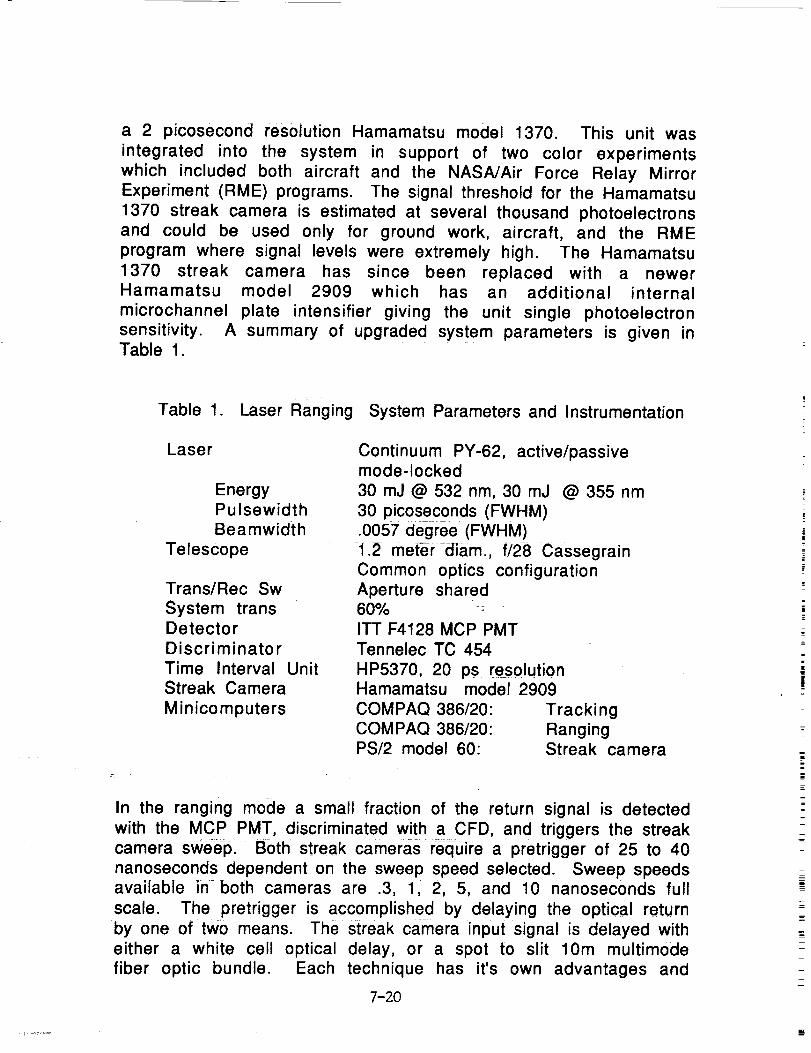
microchannel plate intensifier giving the unit single photoelectronsensitivity. A summary of upgraded system parameters is given inTable 1.
Table 1. Laser Ranging System Parameters and Instrumentation
Laser
EnergyPulsewidth
Beamwidth
Telescope
Trans/Rec Sw
System transDetector
Discriminator
Time Interval Unit
Streak Camera
Minicomputers
Continuum PY-62, active/passivemode-locked
30mJ@532nm, 30mJ @355nm
30 picoseconds (FWHM)
.0057 degree (FWHM)
1.2 me,r-diam., f/28 Cassegrain
Common optics configurationAperture shared60%
ITT F4128 MCP PMT
Tennelec TC 454
HP5370, 20 ps resolutionHamamatsu model 2909
COMPAQ 386/20: Tracking
COMPAQ 386/20: RangingPS/2 model 60: Streak camera
In the ranging mode a small fraction of the return signal is detected
with the MCP PMT, discriminated with a CFD, and triggers the streakcamera sweep. Both streak cameraS require a pretrigger of 25 to 40
nanoseconds dependent on the sweep speed selected. Sweep speedsavailable in both cameras are .3, 1, 2, 5, and 10 nanoseconds full
scale. The pretrigger is accomplished by delaying the optical return
by one of two means. The streak camera input signal is delayed with
either a white cell optical delay, or a spot to slit 10m muitimode
fiber optic bundle. Each technique has it's own advantages and
7-20

disadvantages. The fiber optic bundle is easy to align and has the
largest field of view, but introduces pulse spreading, while thewhite cell has the best throughput, no pulse spreading, but is
difficult to align. To maintain the best differential timing
capability at the receive end an artificial delay on the 532nm pulseis introduced at the laser transmitter. This delay is a dogleg optical
path into a total internal reflection (TIR) cube corner on a
Compumotor linear motor stage. The linear translation stage
provides the differential delay control from -.5 to 10 nanoseconds
additional optical path length for the 532nm pulse so that both
return pulses can be maintained within the 1 nanosecond sweepwindow. The linear motor stage under computer control uses the
differential delay predicted by differencing the Marini & Murray
model delays at 355nm and 532nm The optical delay is adjusted sothat the two spatially separated pulses are incident in the streak
camera slit at approximately the same time. This minimizes
nonlinearity problems in the streak camera sweep. To resolve
simultaneous pulses in the PMT based receiver using the waveform
digitizer two PMT'S must be used.
PRELIMINARY RESULTS
The NASA/Air Force two color RME experiment mentioned earlier
generated the first streak camera returns for the ESLRS [Zagwodzki
et al, 1992]. The RME satellite was very attractive for severalreasons. The RME satellite represented an active, single cube corner
response target with an extremely high lidar cross section (~6x10⁹
m2). With a short pulse laser transmitter and streak camera basedreceiver, the individual cube corners on the satellite, separated by
41.2 mm, could be resolved in time. In the Fall of 1991 the onlystreak camera available at the 1.2m facility for the RME program
was the Hamamatsu model 1370. The high threshold of several
thousand photoelectrons for this streak camera made the RME the
only viable satellite target. Shown in Figure 2 are streak camerareturn waveforms from the RME satellite at 532nm only. Three cube
corners on the satellite could clearly be resolved in time (separation
of 41.2mm). The horizontal sweep speed was 1.2 nanoseconds intime and the laser pulsewidth was 140 picoseconds. Unfortunately
satellite control problems ended the experiment prematurely before
UV operation began.
7-21

E
:>O
E
:>o
C:3
°
o
- .°°
• °o
j-- °_ .
"-_°.
o-" °
" °°-" ._.
.c_____
r __
0 L"4
0
E
apn1!ldwVaA!IDIgU
oc_.
v._ o_• .: _
_c:::l t,,}.c3 --
• .:.,.'°-
:' iN o
- _
_N
IN m-N
o
apn1!IdwV aA!101ai9
E0
ID
n_
n_
oc_
:8<,
- c:_ x-cM O.
j " " -O _
" .-- :N
"'%.-" 70 tr_
". Lc:_--__._><
":'" ;8 o
121u "." . .
. O
-- N__
j_D _3
Tr-.;
° o.-
apnl!IdwV aA!lUlgU
8]
I!c_
- ° _°.
- ..
-.o.
I[3
io
ki-
O
apnl!IdwV a^!IOlaU
ILl
rr
J:
EO11,-
c
_.)
E
l....
Ec
LI..
7-22
The loss of the RME as a target meant satellite streak camera work
had to wait for the installation of the more sensitive Hamamatsu2909 unit. In the interim, two color efforts have continued at the
1.2m facility using the MCP PMT based receiver with a 1 Ghzbandwidth Tektronix model 7912 waveform digitizer. The ranging
system can be configured with two PMT's (one each for 532nm and355nm) or a single PMT (usually the 355nm). For night time
operation, when no bandpass filters are required, a single PMT isused. Since the UV link is the weakest, the PMT with peaked
quantum efficiency at 355nm is used. To resolve two distinct
pulses with the single UV PMT the differential delay at thetransmitter is set to allow at least two nanoseconds offset between
the peaks of the two pulses. This assures adequate separation of
return pulses at the receiver, but reduces the temporal resolution of
the differential time-of-flight measurement.
Figure 3 shows a comparison plot of the theoretical differentialdelay versus the measured delay calculated from the two colorreturns as seen by the Tektronix 7912. The theoretical differential
delay was calculated by differencing the 355nm and 532nm delays
computed using the Marini and Murray model. The Marini and Murraycalculations used the weather conditions from the log file taken
during the pass. This weather information was taken in real-time,so the actual temperature and pressure were not constant. The
pressure changed minimally (1006.27 to 1006.31 millibars) as did
the temperature (14.24 to 14.48 C). The gaps (thinner lines) in theMarini and Murray curve represent times that no weather
information was available, and so the data had to be interpolated for
those regions.
For this pass the linear translator was fixed at 6 nanoseconds. Thisnecessitated a slow sweep setting on the 7912 waveform digitizer
in order to capture both frequency's return waveforms during the
entire pass. Setting the green delay at 6 nanoseconds always placedthe 355nm return ahead of the 532nm return and caused the UV
pulses to move toward the green as the elevation decreased.
The measured differential delay was computed by taking the
inverted raw 7912 waveforms (no smoothing) and computing the
pixel locations of the highest two peaks. The location of these two
pixels was differenced, converted to nanoseconds, and subtractedfrom the fixed 6 nanosecond green delay. This was a "quick-look" at
the data so no interpolation was performed between pixels, and
7-23

X
XX
XxX
X><
X
X
X
XxX
X
X
X
X
X
(gosu] Av7cla
00
0_CO
0_ r----
_rj(1)
(£3
- Z
I_x_l__J
-_ F--"7"
c_ ZZDo
-00
-c5
-00
-c50C',40
(221
0
1--0
w--L
Eo_
0-- _
_ 0
"0 m
0 _
0--o,_
O--
e,i
II,,_
U..
7-24

there was no 7912 calibration data used
nonlinearities in the sweep.
to correct any
The calibration of the linear translator was not performed as
accurately as it will be for streak camera data. The actual zero
point of the translator for the 7912 data was good to approximately
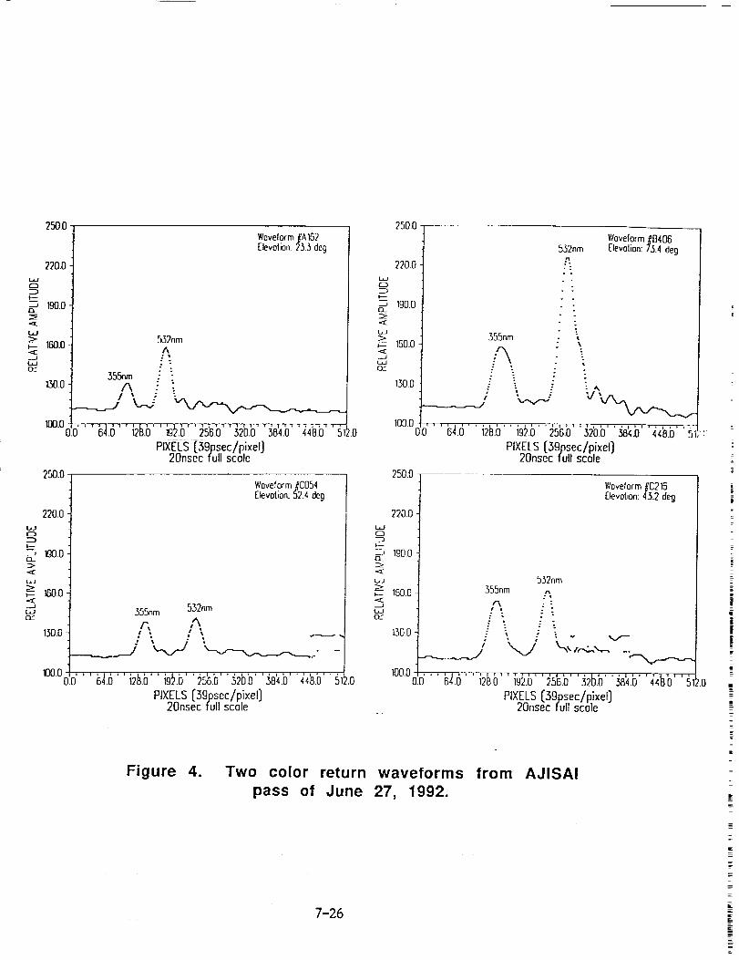
+/- 200 picoseconds. Actual raw 7912 return waveforms atdifferent elevations are shown in Figure 4. In these plots the 7912
data is inverted, but not smoothed in any way.
FUTURE WORK
Two color laser ranging activities will continue at the 1.2m facility
to complete the installation of the streak camera based receiver
with single photoelectron sensitivity. This will enable tracking ofall low earth orbit satellites in two colors and will yield a good
data set for atmospheric model comparisons. Investigative work
will begin in the areas of system automation, and optical time
interval units. [Degnan, 1985]
ACKNOWLEDGEMENTS
The authors wish to thank the Strategic Defense Initiative
Organization Office of Directed Energy for use of the Relay Mirror
Experiment satellite, the Phillips Laboratory of Albuquerque, NewMexico for their coordinating efforts, and the Consolidated Space
Test Center of Sunneyvale, California for their work in providing
NASA the satellite maneuvers for optical engagements.
We would like to thank Arnie Abbott of NASA for his services in
maintaining the 1.2m facility, and Tammy Bertram for her
operational support. We would also like to thank Bendix Field
Engineering Corporation crew members Dick Chabot, Jim Fitzgerald,Dave Grolemund, Mike Seldon, Tom Oldham, and Jack Cheek of
Hughes- STX for their continued effort in support of this program.
REFERENCES
J.J. Degnan, "Satellite Laser Ranging: Current Status and Future
Prospects", IEEE Trans. on Geoscience and Remote Sensing, GE-23, pp.
398-413, July, 1985.
7-25
250.0
220.0
O
190.0.
_aE
160.0<J
130.0
100.0
250.0
220.0W
lg0.0
ELI
1600
n-"
130.0
100.0
Woveform_A162
Elevolion: 233 deg
532nm
A
- .355nm
A " :
0': ' i_L6' ' i2_.b'' {9:5._' ' :#5b.b''._2b.b''._8'4.b''4'4_.b'' _Ii.0PIXELS [3gpsec/pixel]
20nsec full stole
Woveform_C054Etevotion:52.4 deg
355nm 532nm
T- A,,',-vJ -
J
_'' ' W.6'' i2_6'' bL6' '#5'o.b''_2bb....... _4.b'' S_).o384.0
PIXELS [3gpsec/pixel)20nsec full scole
250.0
220.0
igo.o
w
_-- 160.0
__JLLJO_
130.0•
355nm
i
/__.__..._._._/ x.-..,/-...
532nmA
Woveform#8406Elevolion:73.4 deg
I°°°o.o'''i_.[_'' i2_.6'' b).b''_sb.b''_2b.b''_8_b''_&b''fi_;:PIXELS (3gpsec/pixel)
20nsec full scole
250.0
220.0
C)
moo<E
LJ
_-- 160.0
J
Woveform _C216Elevotion:43.2 deg
532nm355nm ,-,
A :_
130.0 . _ ; _ " "v'--
'_._; _','.z,-.._.'_--....
_°°°0.0'' ' W.6'' b_' ' b_.b'' _5'_.b'' _2b.b"'._tb' '4&b' ' _PIXELS [_3gpsec/pixel]
20nsec full scole
Figure 4. TWO color return waveforms from AJISAI
pass of June 27, 1992.
7-26

J. L. McGarry, T. W. Zagwodzki, J. J. Degnan, "Large aperture highaccuracy satellite laser tracking," in Proc. of S.P.I.E. Acquisition,Tracking, and Pointing, Orlando, Florida, April, 1986.
T.W. Zagwodzki, J.F. McGarry, A. Abbott, J.W. Cheek, R.S. Chabot, J.D.Fitzgerald, D.A. Grolemund, "Laser Ranging to the Relay MirrorExperiment (RME) Satellite from Goddard Space Flight Center's 1.2mTelescope Facility", to be published in the Journal of GeophysicalResearch.
7-27