N93-13174 - ntrs.nasa.gov G254 UNDERGRADUATE EXPERIMENT ... Industrial Technology and Education...
14
N93-13174 G254 UNDERGRADUATE EXPERIMENT Doran Barton, Karilyn Bogh, Brett Evans, Steve Folkman, Marc Hammond, Casey Hatch, Neva Herr, Tina Hubble, Jeff Humpherys, Steve Johnson, Mark Lemon, Oscar A. Monje, Kristin Redd, Rich Warby, Tumkur Raghuram (coordinator), and Students from Kinkaid High School. Utah State University Logan, UT 84322-4415 ABSTRACT This paper describes the experiments on payload G254. Each experiment is accommodated in a spacepak and six experiments fly in a full canister. One of the experiments will be housed in a new Isospacepak structure, which will be described briefly. Five of the six experiments have dedicated controllers. The objective of each experiment is discussed. In addition, the operational scenario is provided. INTRODUCTION The Get Away Special (GAS) program is an academic program at Utah State University (USU) which enables students and other educational organizations to participate by designing their own engineering and microgravity science experiments. Five of the experiments on this payload utilize the "spacepak" concept similar to G-008, G-004, G-525 and G- 006. The sixth uses the new "Isospacepak" concept. The external shape and dimensions of each experiment is standardized and each experiment is independently controlled so that experiments can be easily interchanged within the canister. One of the experiments in this GAS canister has been mounted on a new Isospacepak structure that has been machined by Utah State University GAS investigator Tina Hubble and Industrial Technology and Education Department graduate student Joe Greathouse, utilizing Isogrid manufacturing techniques. The Isogrid method consists of milling a series of equilateral triangles out of solid plate stock to produce a structure which is six times as strong as a solid plate of equal weight. In addition, the nodes of the machined structure provide convenient attachment points for experiment components. Each of the nodes has been drilled and tapped, so that a regular, repeating attachment pattern is available to the experimenter. Following its demonstration in this canister, the Isospacepak will be employed in all future Utah State University GAS experiments and will be made available to other organizations desiring to adopt this concept. 151 PRECEDING PAGE BLA_JK NOT FILMED https://ntrs.nasa.gov/search.jsp?R=19930003986 2018-07-08T22:32:09+00:00Z
Transcript of N93-13174 - ntrs.nasa.gov G254 UNDERGRADUATE EXPERIMENT ... Industrial Technology and Education...

N93-13174
G254 UNDERGRADUATE EXPERIMENT
Doran Barton, Karilyn Bogh, Brett Evans, Steve Folkman, Marc
Hammond, Casey Hatch, Neva Herr, Tina Hubble, Jeff Humpherys,
Steve Johnson, Mark Lemon, Oscar A. Monje, Kristin Redd, Rich
Warby, Tumkur Raghuram (coordinator), and Students from
Kinkaid High School.
Utah State University
Logan, UT 84322-4415
ABSTRACT
This paper describes the experiments on payload G254.
Each experiment is accommodated in a spacepak and six
experiments fly in a full canister. One of the experiments
will be housed in a new Isospacepak structure, which will be
described briefly. Five of the six experiments have
dedicated controllers. The objective of each experiment is
discussed. In addition, the operational scenario is
provided.
INTRODUCTION
The Get Away Special (GAS) program is an academic
program at Utah State University (USU) which enables students
and other educational organizations to participate by
designing their own engineering and microgravity science
experiments. Five of the experiments on this payload utilize
the "spacepak" concept similar to G-008, G-004, G-525 and G-
006. The sixth uses the new "Isospacepak" concept. The
external shape and dimensions of each experiment is
standardized and each experiment is independently controlled
so that experiments can be easily interchanged within the
canister.
One of the experiments in this GAS canister has been
mounted on a new Isospacepak structure that has been machined
by Utah State University GAS investigator Tina Hubble and
Industrial Technology and Education Department graduate
student Joe Greathouse, utilizing Isogrid manufacturing
techniques. The Isogrid method consists of milling a series
of equilateral triangles out of solid plate stock to produce
a structure which is six times as strong as a solid plate of
equal weight. In addition, the nodes of the machined
structure provide convenient attachment points for experiment
components. Each of the nodes has been drilled and tapped,
so that a regular, repeating attachment pattern is available
to the experimenter. Following its demonstration in this
canister, the Isospacepak will be employed in all future Utah
State University GAS experiments and will be made available
to other organizations desiring to adopt this concept.
151 PRECEDING PAGE BLA_JK NOT FILMED
https://ntrs.nasa.gov/search.jsp?R=19930003986 2018-07-08T22:32:09+00:00Z
i
i
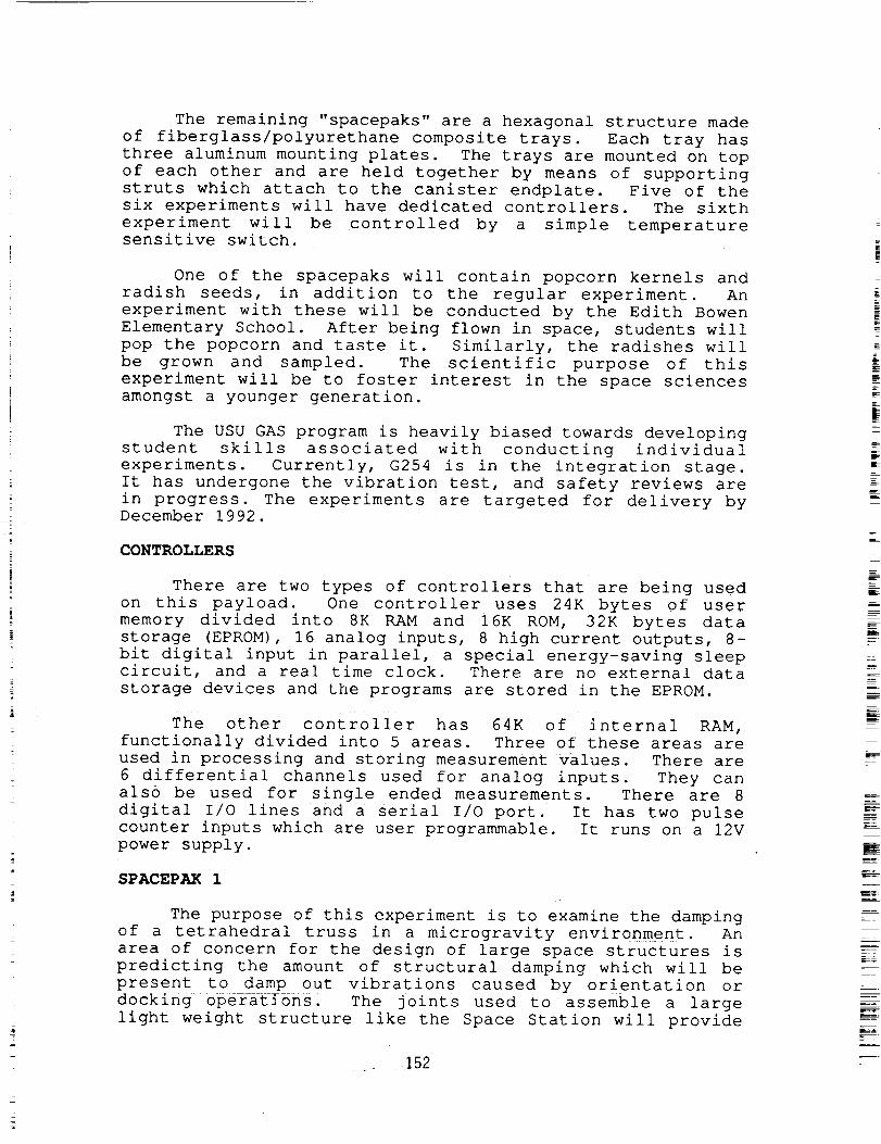
The remaining "spacepaks" are a hexagonal structure made
of fiberglass/polyurethane composite trays. Each tray has
three aluminum mounting plates. The trays are mounted on top
of each other and are held together by means of supporting
struts which attach to the canister endplate. Five of the
six experiments will have dedicated controllers. The sixth
experiment will be controlled by a simple temperaturesensitive switch.
One of the spacepaks will contain popcorn kernels and
radish seeds, in addition to the regular experiment. An
experiment with these will be conducted by the Edith Bowen
Elementary School. After being flown in space, students will
pop the popcorn and taste it. Similarly, the radishes will
be grown and sampled. The scientific purpose of this
experiment will be to foster interest in the space sciences
amongst a younger generation.
The USU GAS program is heavily biased towards developing
student skills associated with conducting individual
experiments. Currently, G254 is in the integration stage.
It has undergone the vibration test, and safety reviews are
in progress. The experiments are targeted for delivery byDecember 1992.
CONTROLLERS
There are two types of controllers that are being used
on this payload. One controller uses 24K bytes of user
memory divided into 8K RAM and 16K ROM, 32K bytes data
storage (EPROM), 16 analog inputs, 8 high current outputs, 8-
bit digital input in parallel, a special energy-saving sleepcircuit, and a real time clock. There are no external data
storage devices and the programs are stored in the EPROM.
The other controller has 64K of internal RAM,
functionally divided into 5 areas. Three of these areas are
used in processing and storing measurement values. There are
6 differential channels used for analog inputs. They can
also be used for single ended measurements. There are 8
digital I/O lines and a serial I/O port. It has two pulse
counter inputs which are user programmable. It runs on a 12V
power supply.
SPACEPAK 1
The purpose of this experiment is to examine the damping
of a tetrahedral truss in a microgravity environment. An
area of concern for the design of large space structures is
predicting the amount of structural damping which will be
present to damp out vibrations caused by orientation or
docking 0perations. The joints used to assemble a large
light weight structure like the Space Station will provide
152

some damping. However, an accepted methodology for
predicting joint damping is yet to be established. A Get
Away Special experiment was assembled to investigate methods
for predicting joint damping in large space structures. A
miniature tetrahedral aluminum truss will be attached to the
wall of a vacuum chamber, and a tip mass attached to the free
end. Oscillations will be induced in the truss structure
with a solenoid and the rate of decay of the vibration modes
will be recorded. The tip mass will be secured using
solenoids during both launch and reentry maneuvers. The
truss chamber will be evacuated through a vent to the shuttle
bay.
Leak testing was conducted on the vacuum cell housing
for the tetrahedral truss experiment. A vacuum pump was used
to reduce the pressure down to approximately 10 -6 Torr
inside the vacuum cell and a helium leak detector was used to
determine if outside air was leaking through any of theseals. A successful leak test was obtained which confirms
that a high vacuum can be maintained inside the vacuum cell.
The goal of this experiment is to record the decay of
the truss while it is vibrating in its fundamental vibration
mode. The controller operates the experiment and measures
the data. The controller pulses the solenoid at the resonant
frequency of the truss for about I0 seconds. Next the
resulting decay of the truss is recorded from either output
of a displacement transducer or a strain gage attached to one
of the truss members. The controller will excite the truss
and record the decay a total of ten times. Since it is
desired to measure the decay in microgravity, the experiment
will be conducted during the first sleep period. A steel tip
mass is attached to the truss to produce a resonant frequency
of approximately 15 Hz. Additional structural support is
provided to the truss tip mass during launch and reentry by
the truss locking mechanism. The locking mechanism is in
place during launch. Shortly after launch the stepper motor
is activated to unlock the truss. After the testing is
complete the truss is locked again for reentry. In the event
the locker mechanism fails to relock the truss, the vacuum
cell is designed to limit the deflection of the truss. The
structural diagram for this experiment is shown in fig. i.
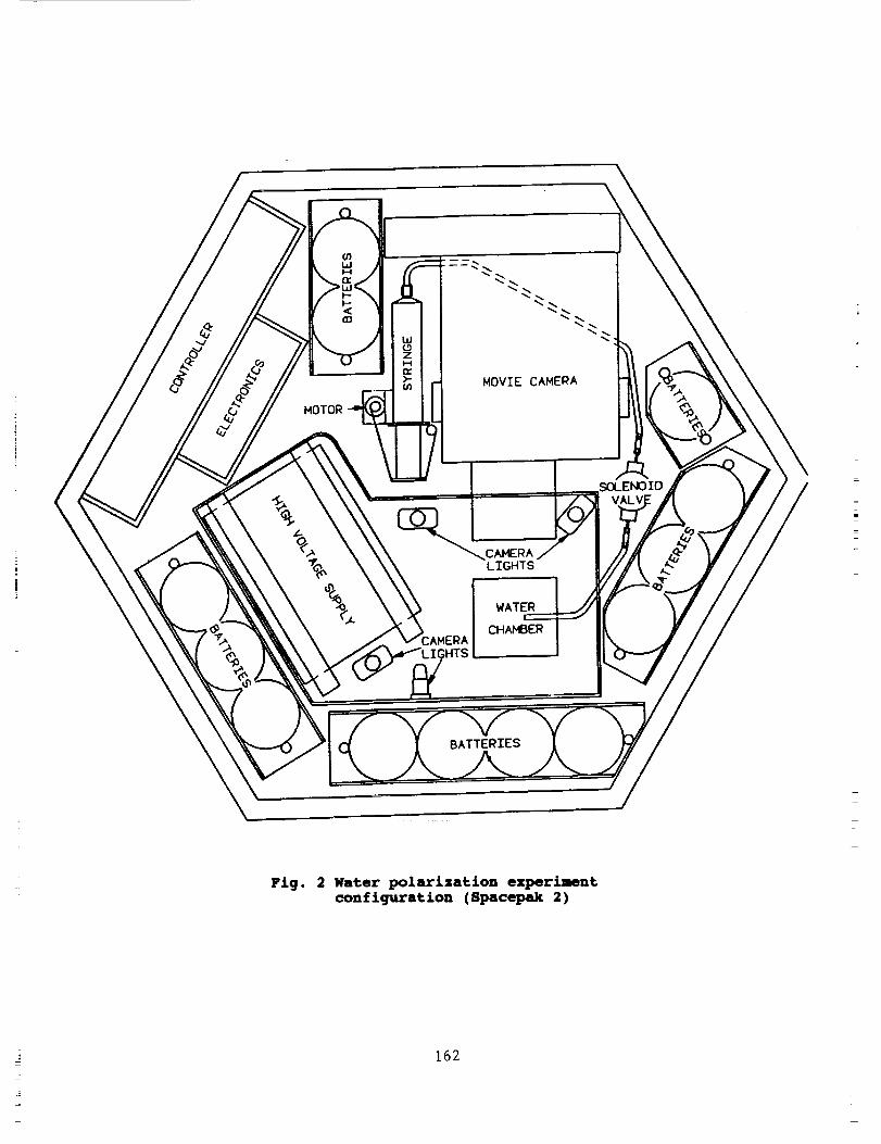
SPACEPAK 2
The objective of this experiment is to examine the
behavior of an isolated water droplet suspended in an
electromagnetic field. Theory suggests that when a droplet
is polarized under a very strong field (of the order of 10-20
kV) it elongates into a prolate spheroid. The forces exerted
on the water droplet are the normal stress from the electric
field, the surface tension from the water droplet, and the
153

constant internal and external pressures exerted on the
droplet (1,2). Although the internal and external pressures
of the droplet are constant they are hot constant over the
surface of the droplet (I). To balance this inconsis£ency
there must be an induced flow arising from the viscous stress
of the droplet (2). This flow is shown to be both inside and
outside of the droplet_ These forces are believed to be themechanics of the deformation of these water droplets.
At some point the droplet will become unstable. This
point is labeled as the critical field strength. The
critical field strength for a conducting incompressible
(liquid) droplet is an inverse function of the original
radius of the spheroid. After the critical field strength is
reached, some droplets would expand until they disintegrate
while others expand until they form sharp points from which
jets of liquid form. The droplet can expand to an oblate or
a prolate spheroid depending on the ratios of three physical
parameters of the medium of the droplet. The parameters are
electrical conductivity, viscosity and permittivity. These
ratios determine the shape of the droplet (1,2)•
The water polarization experiment depends upon 13 lead-
acid batteries for all its electrical needs. Each battery
delivers 2 V and 5 amp-hrs. Four batteries are needed just
i to power the controller. The main component of the
experiment is the water chamber. It consists of two parallel
plates with a separation distance of about 4 cm. The plates
are made of aluminum and are 5 cm square in area. The volume
inside allows a wa£er droplet of radius I cm. A needle of
nylon will be used to produce the water droplet. A high
voltage supply which requires 15 V and delivers about 18kV
output is required. A super 8mm movie camera will be used to
photograph the water droplet during the experiment.
The aim in this experiment is to confirm a relationship
between the eccentricity of the ellipsoid and the applied
voltage across the plates. The experiment configuration is
_--___sh_own_ in fig, 2.
SPACEPAK_3 -
This experiment is called Project Panchamama. Project
Panchamama is a biological experiment designed to study the
effects of microgravity on photosynthesis• Physiological
data of this nature will be useful in elucidating the effects
of microgravity on the performance of plants• Microgravity
may affect photosynthesis in one of two ways: (i) by altering
the diffusion of gases (i.e.. C02 ) into cells or (ii) by
altering c_!ilfunction due to redistribution of water or
altering hydrostatic forces. The experiment has been
designed to study photosynthesis by using chlorophyll
fluorescence measurements. Chlorophyll fluorescence is a
154

sensitive indicator of the efficiency of photosyntheticreactions and has been used extensively to monitor plantstress.
Biological experiments are inherently more complex thannon-biological ones, because measurements must be obtainedfrom a living organism. The GAS CAN environment is extremelyharsh for living organisms because of the pre-flight dormancyperiod (30-90 days), exposure to high g-forces duringliftoff, and followed by approximately 7 days of apotentially harmful thermal environment. Furthermore, theatmosphere of the GAS CAN is composed of nitrogen, and theexperiment will be unable to provide life support during thepre-flight dormancy period. GAS payload temperatures werefound to reach minimums close to -20oc. The sampletemperature during the experiment must be maintained betweena maximum of 30oc and a minimum of 5oc, so as to avoidthermal damage of the samples. Fluctuating temperatures alsoaffect the thermal drift of electronic components and theheating rate experienced by the organism.
The experiment will rehydrate a lichen in orbit, andfluorescence measurements will be recorded using a simplefluorometer. A lichen, a symbiotic poikilohydric organism
composed of algae and fungus, was chosen because it can
remain dormant for many months without the loss of viability.
The organisms will be housed within a compact life support
system composed of an airtight chamber, and a water
reservoir. The chamber is made of aluminum and is sealed by
a static o-ring. The chamber atmosphere will be air
containing 21% 02 and 600-1200 ppm of CO2 at 1 atm of
pressure. A nylon sample holder assembly is located inside
the chamber. It consists of two aluminum sample holders, six
incandescent glow lights, and a sensor arm. The two sample
holders are independently connected to a water reservoir.
Water is pumped into each sample holder with a peristaltic
pump. Sample holder temperature is controlled with a feedback
circuit composed of a peltier heater. All electrical
connections into the gas tight chamber are made through three
20 pin feedthrough connectors.
Water is passed into the chamber through an o-ring
sealed water feedthrough connector. The reservoir consists
of a 10cm long, 5cm diameter solid PVC pipe and holds 150 ml
of distilled water. The reservoir will be insulated and
heated by a thermofoil heater. Water flow is regulated by
two individually operated, normally closed solenoid valves.
The experiment will be activated by a baroswitch, which
will power up the control system. Data acquisition is
accomplished through 16 single-ended input channels.
Control is accomplished through a memory mapped multiplexer
and switching board. The control system will heat the water
155

reservoir to 10°C, and then each sample holder will be
rehydrated. The glow lights will then be turned on to start
photosynthesis to allow for a period of normal growth and
recovery from the long pre-launch dormancy period.
The data acquisition portion of the experiment will
begin after a suitable time for rehydration. The data
acquisition consists of a sensor arm shaped like an X, that
holds a pair of photometric sensors in each leg of the X.
Each leg contains a chlorophyll meter and a fluorometer.
The sensor arm is moved directly over the samples during the
measurement sequence by a linear actuator. Measurements
will be made at five different temperatures in order to
characterize the temperature response of the organism.
The power required to provide a controlled temperature
regime was estimated from the expected power use of both the
water reservoir and the sample holders. The water reservoir
will require 2 watts of continuous power to maintain the
water temperature at 10°C if the GAS CAN temperature is 5oc,
and i0 watts if the GAS CAN temperature drops to -10°C.
Each sample holder will require 0.88 Watts continuously to
heat the sample at a heating rate of 2°C/min. The second
sample holder will be rehydrated only if the payload
temperature is above -5°C. This arrangement allows both
redundancy and economy of power in the event of encountering
an extremely harsh temperature environment.
The life support system presently being developed
allows certain biological experiments to be performed in the
GAS CAN. The nature of these experiments was found to be
limited by the reduced capability for life support during
the pre-launch phase, and thus dictated by the choice of
test organism. Furthermore, the use of photometric probes
for measuring physiological parameters allows simplicity of
design, in-flight data acquisition, and low mass and power
requirements.
SPACEPAK 4
The bubble micro-gravity experiment is designed to study
the characteristics of a small three-dimensional bubble
structure inside a NASA GAS canister. It is completely self-
contained and requires a signal to initiate the experiment
operation. The primary goals of the experiment are to: (i)
observe the formation process of the bubble, (ii) look for
evidence of drainage in the bubble after it has been formed,
(iii) look for interference bands due to bubble wall
thickness gradients, and (iv) observe surface tension induced
motions on the bubble surface. The bubble experiment data
will be gathered by an 8 mm movie camera. Supplemental data
will be measured in analog form and stored in a memory
module. The bubble itself will be formed using a fluid which
156

is 85% (by volume) Dow Silicon diffusion pump oil and 15% 3M
FC430 surfactant.
The experiment consists of 5 major subsystems: command
and control, a bubble blower, camera and lighting, power and
heaters.
The command and control subsystem is run by a
controller. The controller has 8 digital output lines. The
controller is electrically isolated from the experiment
apparatus through the use of optical isolators and a separate
power source.
The bubble blower is the crux of the experiment. It
consists of an aluminum block onto which other parts are
attached. The block serves as a bubble material reservoir.
A blower aperture is affixed to this block. The bubble is
formed at the blower aperture. Two linear actuators are
also attached to this block, as are the DC stirring motor,
two thermofoil heaters, and two thermistors. The stirring
motor is used to mix the bubble material prior to the bubble
formation sequence. One of the linear actuators is used to
unseat a spring-loaded check valve. This valve normally
keeps the bubble material inside the reservoir. The second
linear actuator is used to force the bubble material to flow
to the top of the bubble aperture. The thermofoil heaters
are used to keep the bubble material at a temperature above
15oc. One of the two thermistors is used in a closed-looped
heater subsystem. The second thermistor is used to monitor
the bubble blower temperature.
An 8 mm movie camera is used to record all of the bubble
formation activity. A fluorescent lamp is used to provide
lighting during the filming sequences. The light is mounted
directly behind the blower block, on the other side of the
camera. A small incandescent lamp is used to heat the
bubble surface. The heating is not uniform, which causes a
gradient in the surface tension. The induced surface tension
gradient will cause movement of the material on the bubble
surface. This movement will be filmed by the camera.
All energy for operation of the experiment comes from
several sets of lead-acid batteries. One set of 6 cells is
devoted to the controller, while a Second set of 12 cells is
devoted to the experiment power. This was done, in part, to
completely electrically isolate the controller from the
experiment.
Thermofoil heaters are attached to the base of the
blower block for temperature control purposes. Once powered
up, the heater subsystem does not require attention from the
controller. Power is supplied to the thermofoils whenever
the temperature of the blower block falls below 15Oc.
157

SPACEPAK 5
This project was proposed by Kinkaid High School. Since
USU began supporting this project, various students have
assisted in its development. Since the delays that resulted
from the Challenger accident, the USU GAS program has taken
the initiative to complete this project. The controller has
been completed and tested.
The objective of this experiment is to distill a mixture
of two fluids in microgravity using a temperature
differential. The fluids intended for the experiment are
trichlorotrifluoroethane and carbon tetrachloride.
Significant properties of these fluids that require
examination include boiling point, vapor pressure, and
toxicity and flammability characteristics.
This experiment is contained within a composite
hexagonal spacepak. Lead-acid batteries supply four power
sources of 35V, 5V, 10V, and 5V. These batteries are
contained within a support structure. The fluid containment
system includes one solenoid valve, two aluminum containers
with a fluid capacity of 13.7 ml each, and brass fittings. A
thermofoil heating element wraps around one container. It
requires a 35V power supply. The c0n£roiling system consists
of a mechanical relay, one USU GAS switch, two voltage
regulators for each of the 5V power supplies, a printed
circuit board, and Teflon coated wires. A voltage regulator
stand, fluid chamber stand and two aluminum base plates
secure the experiment structurally.
The experiment starts when the NASA signal is received
by the USU GAS switch. The USU GAS switch activates the
relay that connects all power sources to the controller. The
controller receives the power and regulates all power output
and operation. A thermistor is attached to the bottom of the
aluminum container which has the heating element. The
thermistor, in combination with another resistor, makes a
variable voltage divider that provides input for a Schmitt
trigger. Resistor selection controls the operating
temperature and the fluctuation of temperature during
feedback about the desired operating temperature. The heater
turns on with the power up of the controller. When the
operating temperature is reached a binary counter turns on.
The valve that separates the two fluid chambers also opens up
as the controller receives power. The binary counter runs
for approximately three hours. During this time the Schmitt
trigger of the controller powers the heater according to the
resistance of the thermistor so that a temperature level may
be maintained. Three J-K flip flops aid in system operation.
When the counter returns to zero, the valve is closed, the
controller shuts down, and the project remains dormant.
Completion of this experiment involves analyses of the
_=
@
158

chemical composition of the fluid in each container and
comparison with results of distillation experiments in the
earth's gravitational field. A figure of the fluid
containers and the solenoid valve is shown in fig. 3.
SPACEPAK 6
Float Zone Instability Experiment (FiZIE) aims to
investigate convective instabilities in float zone
geometries. The primary goal of the experiment is to verify
the Plateau Instability limit, which states that in zero
gravity a fluid cylinder is unstable when the ratio of length
L to radius R exceeds 2K. This will be accomplished by
creating four independent liquid wax bridges with varying
lengths and radii. In addition, by allowing the liquid wax
to resolidify under "non-quiescent" conditions, a sensitive
test of background g-levels can be qualitatively measured bythe common distortion in the resolidified float zones.
Four columns of solid parowax with radii ranging from
0.5 to 0.7cm and lengths ranging from 3 to 6 cm are suspended
in an array between two copper supports. At one end of each
of the wax columns is connected a heater which will be used
to melt the wax. The four heaters will be operated by eight
lead-acid batteries. The heaters operate at i0 watts. To
melt the wax, the heaters need to reach about a temperature
of 70°C. A circuit known as a Schmitt trigger will be used
to reach and maintain this temperature for 30 minutes. A
programmable controller will be used to control the
experiment, switches and time-variables. The controller will
receive its power from 4 lead-acid batteries. Upon the end
of the mission, the resulting shapes of the resolidified
float zones will be qualitatively analyzed.
159

References
i. Taylor, G.I. Studies in Electrohydrodynamics. I. The
Circulation Produced in a Drop by an Electric Field. Proc.
R. Soc. Lond. A 291, pp.159-166 (1986)
2. Ajayi, 0.0., A note on Taylor's Electrohydrodynamic
Theory, Proc. R. Soc. Lond. A 364, pp.499-507 (1978)
160

IZv
50-psivalve
35V
• - volume 13.7 ml
volume 13.7 ml
I TOTAL VOLUME 34.6 ml I
thermistor
brass
I
tI
I
II
I
I
3 cm
8 cm
Fig. 3 Fluid containers and Solenoid valve (Spacepak 5)
161
MOTOR
\
'---- MOVIE CAMEPA
LIGHTS
WATER
_AMB_
BATTERIES
Fig. 2 Water polarization experiment
configuration (Spacepak 2)
162

ITETR.AHEDRAL TRUSS EXPERINENTI
WIRE PASSTHRUFITTING
LATCHINGRELAY
TRUSS JOINTTIP MASS
TRUSS MEMBERSOLENOID
TRUSSMOUNTINGBRACKET
FUSE
ACTUATOR FORLOCKING MECHANISM
BATTERIES FORSOLENOID & ACTUATOR
LOCKINGMECHANISM
FUSE
VACUUM CELLFITTINGS&FLEXIBLE TUBING
BATTERIES FORCONTROLLER
Fig. 1 Structural diagram of Spacepak 1
163

=