N88- 23746 - NASA · PDF fileN88- 23746 PRELIMINARY ... stall/spln resistance with minimum ......
42
N88- 23746 PRELIMINARY AERODYNAMIC DESIGN CONSIDERATIONS FOB _'_/ _ O-__'_ ADVANCED LAMINAR FLOW AIRCRAFT CONFIGURATIONS Joseph L. Johnson, Jr., Long P. Yip, and Frank L. Jordan, Jr. NASA Langley Research Center Hampton, Virginia 23665 SUMMARY Recent aerodynamic research on advanced aircraft configurations has revealed some important design considerations that affect aerodynamic efficiency and performance, stability and control, and safety of flight. Modern composite manufacturing methods have provided the opportunity for smooth surfaces that can sustain large regions of natural laminar flow (NLF) boundary-layer behavior and have stimulated interest in developing advanced NLF airfoils and improved aircraft designs. The present paper overviews some of the preliminary results obtained in exploratory research Investigations on advanced aircraft configurations at the NASA Langley Research Center. Results of the initial studies have shown that the aerodynamic effects of configuration variables such as canard/wlng arrangements, airfoils, and pusher-type and tractor-type propeller installations can be particularly significant at high angles of attack. Flow field interactions between aircraft components were shown to produce undesirable aerodynamic effects on a wing behind a heavily loaded canard, and the use of properly designed wing leadlng-edge modifications, such as a leadlng-edge droop, offset the undesirable aerodynamic effects by delaying wing stall and providing increased stall/spln resistance with minimum degradation of laminar flow behavior. INTRODUCTION In recent years, there have been significant performance improvements in general aviation aircraft from the realization of increased amounts of NLF (see refs. I through 8). This result was achieved in part through advanced NLF airfoil design and modern construction materials and fabrication techniques such as composites and milled or bonded aluminum skins. In addition, there have been design trends toward unconventional aircraft arrangements incorporating unusual features such as canards, tandem wings, and multiple surfaces to obtain performance gains. Preliminary results suggest that the use of some of these features provides weight savings, improved cabin layouts, and improved aerodynamic characteristics which can provide significant performance benefits and increased overall operating efficiency and utility. Examples of such advanced designs are the Gates LearJet/Plagglo GP-180, a three-surface configuration with twin- pusher englnes mounted on the wing (fig. I), and the Beech Aircraft Corporation Starshlp I, a canard configuration with twln-pusher engines mounted on the wing (fig. 2). Although the advanced aircraft designs with new 185 PP, ECED G PAGEBI.Ai NOT mLMm https://ntrs.nasa.gov/search.jsp?R=19880014362 2018-05-03T13:12:02+00:00Z
Transcript of N88- 23746 - NASA · PDF fileN88- 23746 PRELIMINARY ... stall/spln resistance with minimum ......
N88- 23746
PRELIMINARY AERODYNAMIC DESIGN CONSIDERATIONS FOB _'_/ _ O-__'_
ADVANCED LAMINAR FLOW AIRCRAFT CONFIGURATIONS
Joseph L. Johnson, Jr., Long P. Yip, and Frank L. Jordan, Jr.
NASA Langley Research Center
Hampton, Virginia 23665
SUMMARY
Recent aerodynamic research on
advanced aircraft configurations has
revealed some important design
considerations that affect aerodynamic
efficiency and performance, stability
and control, and safety of flight.
Modern composite manufacturing methods
have provided the opportunity for
smooth surfaces that can sustain large
regions of natural laminar flow (NLF)
boundary-layer behavior and have
stimulated interest in developing
advanced NLF airfoils and improved
aircraft designs. The present paper
overviews some of the preliminary
results obtained in exploratory
research Investigations on advanced
aircraft configurations at the NASA
Langley Research Center. Results of
the initial studies have shown that the
aerodynamic effects of configuration
variables such as canard/wlng
arrangements, airfoils, and pusher-type
and tractor-type propeller
installations can be particularly
significant at high angles of attack.
Flow field interactions between
aircraft components were shown to
produce undesirable aerodynamic effects
on a wing behind a heavily loaded
canard, and the use of properly
designed wing leadlng-edge
modifications, such as a leadlng-edge
droop, offset the undesirable
aerodynamic effects by delaying wing
stall and providing increased
stall/spln resistance with minimum
degradation of laminar flow behavior.
INTRODUCTION
In recent years, there have been
significant performance improvements in
general aviation aircraft from the
realization of increased amounts of NLF
(see refs. I through 8). This result
was achieved in part through advanced
NLF airfoil design and modern
construction materials and fabrication
techniques such as composites and
milled or bonded aluminum skins. In
addition, there have been design trends
toward unconventional aircraft
arrangements incorporating unusual
features such as canards, tandem wings,
and multiple surfaces to obtain
performance gains. Preliminary results
suggest that the use of some of these
features provides weight savings,
improved cabin layouts, and improved
aerodynamic characteristics which can
provide significant performance
benefits and increased overall
operating efficiency and utility.
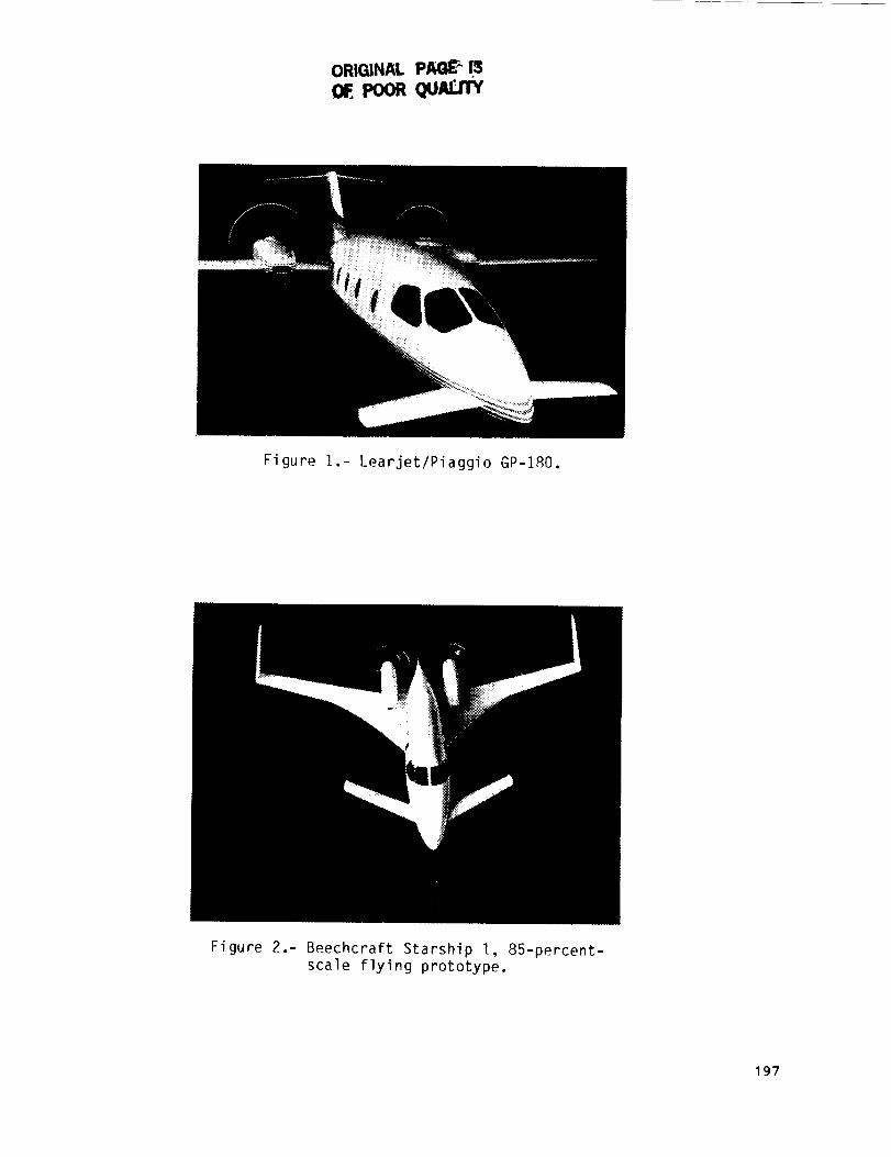
Examples of such advanced designs are
the Gates LearJet/Plagglo GP-180, a
three-surface configuration with twin-
pusher englnes mounted on the wing
(fig. I), and the Beech Aircraft
Corporation Starshlp I, a canard
configuration with twln-pusher engines
mounted on the wing (fig. 2). Although
the advanced aircraft designs with new
185
PP,ECED G PAGEBI.Ai NOT mLMm
https://ntrs.nasa.gov/search.jsp?R=19880014362 2018-05-03T13:12:02+00:00Z

technology features and modern
construction techniques appear very
promising from performance
considerations, information on the
aerodynamic characteristics of
unconventional configurations, par-
ticularly those with strong flow-field
interactions, is very limited. For this
reason, several recent system studies
and wlnd-tunnel investigations have
been initiated to provide a technology
base for evaluating the aerodynamic
characteristics of the advanced
designs. The initial results of these
wind-tunnel investigations indicate the
importance of recognizing the strong
aerodynamic interactions that can
result from placing propulsion systems
or control surfaces in unconventional
locations.
Flow-fleld interactions between
aircraft components can produce
undesirable aerodynamic effects, and
the use of wing leading-edge
modifications may be required to offset
the undesirable aerodynamic effects and
improve stall/spln resistance.
Preliminary results have shown that the
application of a properly designed wing
leading-edge droop to advanced NLF
wings can improve the stall/spin
resistance of these wings with minimum
performance degradation. This paper
presents some of the initial results of
the exploratory aerodynamic
investigations for several of the con-
figurations investigated and discusses
the significance of the results from
overall performance and stability and
control considerations.
SYMBOLS
BL
C
c
c
CD
CD c
CL
CL c
C1P
Cm
Cm c
C n
CT
AFc
Fp
AFw
LE
q
butt llne
canard
wing mean aerodynamic chord, ft
local chord, ft
drag coefficient, Drag/qS
canard drag coefficient
lift coefficient, Lift/qS
canard lift coefficient,
Canard llft/qS c
roll damping
pltching-moment coefficient,
Pitching moment/qSc
canard pitching-moment
coefficient
section normal-force
coefficient, Normal force/qc
propeller thrust coefficient,
Thrust/qS
incremental force on canard due
to power, ib
propeller normal force, lb
incremental force on wing due
to power, lb
leading edge
dynamic pressure, lb/ft 2
b wing span, ft RN
S
Reynolds number
wing area, ft 2
186

Sc
WL
x
Y
8
6e
canard area, ft 2
water line
local wing chord, ft
lateral distance from wing
centerline, ft
angle of attack, deg
sideslip angle, deg
elevator deflection, deg
Notation:
C.G. center of gravity
MODELS AND TEST CONDITIONS
The models used to provide
aerodynamic information for discussion
in this paper include the following
configurations:
O Canard, slngle-englne pusher
0 Canard, slngle-engine tractor
Conventional single-englne
tractor design
Conventional business jet
design
0 Three-surface design
O Over-the-wlng propeller design
The canard, pusher configuration
was a full-scale model of a propeller-
driven homebuilt aircraft which has
demonstrated good performance and a
high level of stall/spln resistance in
operational use (see refs. 3 to 5).
The canard, tractor configuration was a
sub-scale model of an advanced general
aviation design which incorporated a
relatively close-coupled canard and an
aft-mounted wing of relatively low
sweep (see ref. 6). A single-slotted
elevator on the canard provided pitch
control. For the canard models, an
auxilary balance was used to measure
canard loads independently from the
total aerodynamic loads measured on a
main balance.
The conventional single-engine
tractor model and the conventional
business jet model represent
configurations incorporating advanced
NLF airfoils for improved performance
(see refs. 7 and 8). One of the unique
features of these configurations was
the application of leading-edge droop
designs which increased stall/spin
resistance without significantly
degrading NLF performance (see ref.
9). The three-surface design and the
over-the-wlng propeller design were
configurations derived from a general
purpose model used in generic studies
to explore low-speed stability and
control characteristics of advanced
designs including the effects of power
with aft-mounted engines (see refs. 10
and 11). The wind-tunnel results
presented in this paper were obtained
in investigations conducted in the
Langley 30- by 60-Foot Wind Tunnel and
12"Foot Low-Speed Wind Tunnel.
RESULTS AND DISCUSSION
Canard, Single-Englne Pusher
Presented in figure 3 is a
photograph of the large-scale canard,
slngle-englne pusher configuration
investigated in the Langley 30- by 60-
Foot Wind Tunnel. The model was
constructed with smooth fiberglass
187
surfaces and was equipped with pressure
ports in the canard and wing to give
detailed pressure distribution data.
This investigation revealed many
important design considerations for
canard aircraft and pointed out the
significance of these design features
on performance, stability, and control
characteristics (see refs. 4 and 5).
Some of the more significant results of
the investigation include: (I) the
influence of the canard downwash on the
wing aerodynamics; (2) the large
regions of NLF on the smooth fiberglass
surfaces; (3) the effect of canard
airfoil section on stability and
control; and (4) the effect of the
engine location on propeller efficiency
and stability and control. One of the
most important, unexpected findings
resulting from the wind-tunnel
investigation was the discovery of
large regions of NLF boundary-layer
behavior. Using a sublimating chemical
technique for transition visualization,
it was determined that NLF existed back
to 55-percent chord on the canard, 65-
percent chord on the wing, and 60-
percent chord on the winglets for a
cruise attitude (see fig. 4). Figure 5
shows the flight vehicles which were
used to verify the amount of NLF
indicated in the wind-tunnel tests.
Figure 5(c) shows the results of
chemical sublimation tests conducted in
flight and illustrates that the amount
of NLF achieved in flight on the canard
was similar to that measured in the
wind tunnel (back to 55-percent chord
station). As part of the 30- by 60-foot
wlnd-tunnel investigation, tests were
conducted to force premature boundary-
layer transition on the canard by
either carborundum grit applied at 5-
percent chord or by water spray. These
tests were initiated because of pilot
reports of such aircraft experiencing a
pitch trim change when entering rain.
To determine whether this trim change
was the result of early laminar to tur-
bulent boundary-layer transition caused
by rain, a test apparatus was used for
rain slmulat_on as shown in figure 6.
The test apparatus consisted of a
horizontal boom mounted in the wind
tunnel about 4 chord lengths ahead of
the canard. Results of the forced
boundary-layer transition tests
(presented in fig. 7) show that forced
transition by either carborundum g_tt
or rain simulation resulted in a
significant reduction in the canard
lift-curve slope and increased canard
drag. Figure 8 shows that fixed
boundary-layer transition on the canard
caused, as expected on the basis of
premature traillng-edge flow separation
and reduced canard llft-curve slope, an
increase in longitudinal stability and
loss of elevator control effectiveness.
These results point out the importance
of airfoil selection to avoid changes
in llft characteristics with loss of
laminar flow. Advanced NLF airfoils
have been designed to minimize the loss
in llft due to premature transition
(see ref. 7). Advanced NLF airfoils
will be examined in more detail in
subsequent sections of this paper.
Included in the investigation of
canard airfoil design was a study of
the effect of canard configuration on
stall/post-stall behavior. Figure 9
shows the two airfoils investigated to
illustrate the effects of camber and
shape on stability and control.
Presented in figure IO(a) are pitching-
moment characteristics of the aircraft
with the two different canards, and the
data show significant differences in
the stall/post-stall angle-of-attack
range. For either airfoil
configuration, the data show a stable
18R
break at wing stall, but in the post-stall angle-of-attack range the NACA0012 airfoil shows a markeddestabilizing trend and positivepitching momentsat high angles ofattack. The significance of such atrend is that for certain landingconditions there may exist thepossibility of inadvertently enteringthe post-stall angle-of-attack regionand experiencing a deep-stall trimcondition. The data of figure 10(b)show the importance of airfoil designin avoiding undesirable deep-stallcharacteristics. The significant pointof figure IO(b) is that the GU25-5(11)8airfoil has a relatively flat lift-curve slope following the stall,whereas the NACAOO12airfoil shows anabrupt loss of llft at the stall andthen an increase in lift in the post-stall angle-of-attack range. Theincrease in canard llft-curve slope inthe post-stall angle-of-attack range isvery destabilizing because an increase
in canard llft tends to aggravate the
destabilizing effect of wing stall on
pitch stability for a canard
arrangement. The stability and control
of canard arrangements will be
discussed in further detail in the
section of this paper dealing with
tractor engine arrangements.
Figure 11 presents a sketch to
introduce the subject of canard
downwash and vortex-wake interaction
effects on the main wing. The two main
points to be discussed are the canard
downwash on the inboard portion of the
wing, and the canard vortex flow which
introduces an upwash on the wing tip.
Figure 12 presents measured section
normal-force coefficient data to show
the effect of the canard wake on the
wing and indicates, as expected, that a
reduction in span loading occurs
inboard and an increase in span loading
occurs at the wing tip. The results of
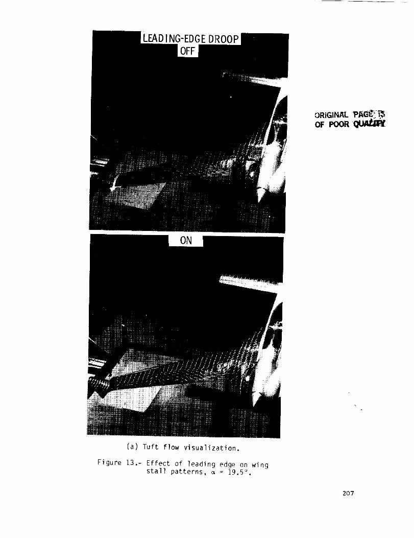
tuft flow studies (fig. 13(a)) show
that the aircraft experiences spanwlse
flow on the wing and severe tip stall
at a = 19.5 °. The use of a leading-
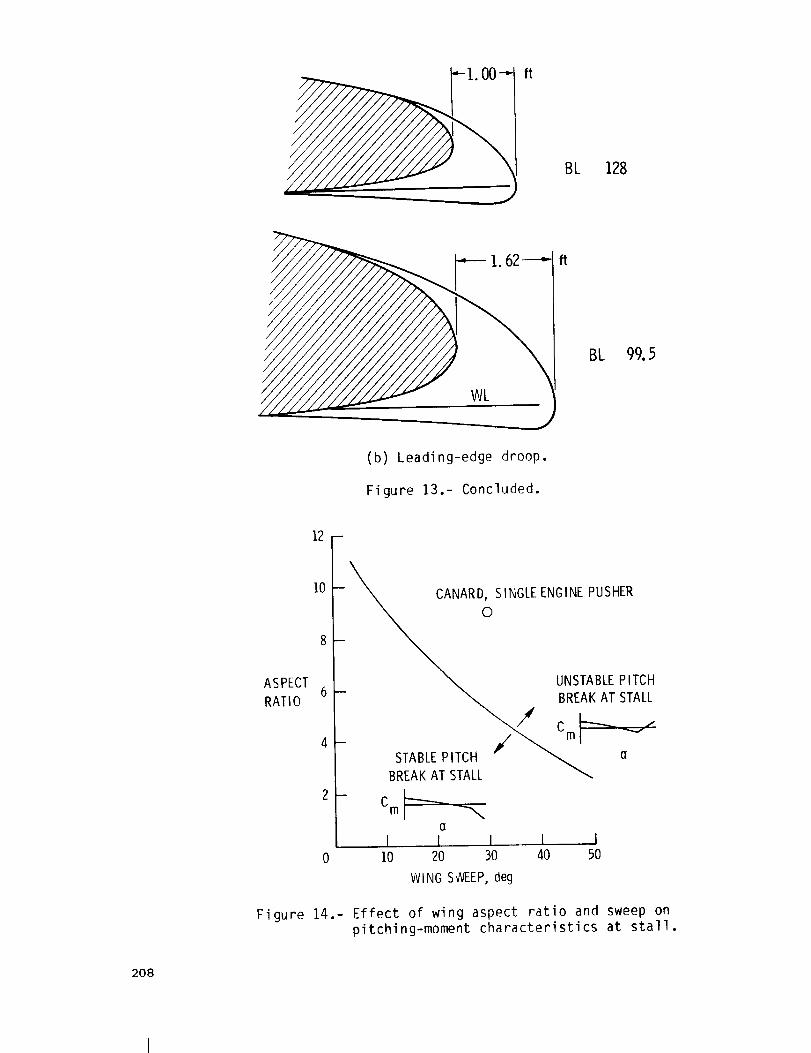
edge droop, shown in cross section in
figure 13(b), is shown by the tuft
photograph of figure 13(a) to provide
attached flow at the wing tip.
The importance of wing leadlng-edge
treatment for swept wings is
illustrated in a plot of aspect ratio
against wing sweep in figure 14. The
figure was taken from reference 12 and
shows that swept wings with high aspect
ratios tend to have an unstable
pitchlng-moment break at the stall due
to tip stall. The figure does not take
into account the effects of such items
as wlnglets or canard vortex flow on
the wing tip stall. Such effects
emphasize the need for additional
research on the use of wing leading-
edge treatment for improved stall
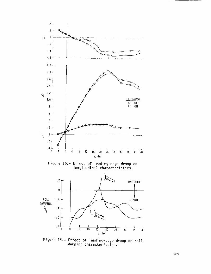
characteristics. Figure 15 shows the
stabilizing effect of the wing leading-
edge droop on the pltching-moment
characteristics of the canard single-
engine pusher configuration, and figure
16 shows the stabilizing effect of the
leadlng-edge droop on roll damping.
Model and airplane flight tests
verified the damping-ln-roll data of
figure 16 and showed that the wing
leadlng-edge droop eliminated a wing
rock tendency of the basic airplane
configuration for aft center-of-gravity
location.
Canard, Single-Englne Tractor
Discussion of the canard, single _
engine tractor configuration emphasizes
the effects of canard airfoil section
189
and the effects of power on longitudi-
nal stability characteristics. More
complete discussion of the overall
stability and control characteristics
of the tractor configuration is
presented in reference 6.
Presented in figure 17 is a
photograph of the canard, tractor model
mounted for static wlnd-tunnel tests in
the Langley 30- by 60-Foot Wind
Tunnel. The model has a closely
coupled canard-wing arrangement with
the canard placed slightly above the
wing. Power for the subject model was
supplied by a tip-turbine air motor
driven by compressed air.
Figure 18 shows a comparison of the
effects of power on the pitching-moment
characteristics of the canard, tractor
and pusher configurations for climb
power (CT = 0.4) and aft center-of-
gravity conditions. The data show
that the power effects were
destabilizing for the tractor model and
stabilizing for the pusher model. The
large nose-up trim changes for the
tractor model were caused by a
combination of direct propeller normal
force and induced effects on the canard
and wing. As indicated in the sketch
of figure 18, the rearward location of
the propeller results in a propeller
normal force which produces a nose-down
or stabilizing pitching moment.
Figure 19 shows the effect of
canard airfoil section on the pitching-
moment characteristics of the tractor
configuration. Of particular interest
in figure 19 is the relative difference
between the pitching-moment data of the
NACA 23018 airfoil and two NLF
airfoils, the GU25-5(11)8 and the
NLF(1)-0416, in the post-stall angle-
of-attack range. As noted in the
preceding section, the post-stall
stability characteristics of canard
configurations can be greatly
influenced by the canard airfoil. For
the three airfoils investigated, the
NACA 23018 gives the most destabilizing
pitching-moment trends at post-stall
angle of attack. The reason for this
trend _s that the NACA 23018 is a
relatively thin airfoil which exhibits
a sharp stall and an increase in lift-
curve slope at post-stall angles of
attack and becomes very
destabilizing. The other airfoils of
figure 19 tend to have a relatively
flat lift curve at stall and,
therefore, give more desirable post-
stall stability contributions.
As part of the exploratory research
on the tractor design, tests were
continued to examine in more detail the
aerodynamic characteristics of the
GU25-5(11)8 and the NLF(1)-0416
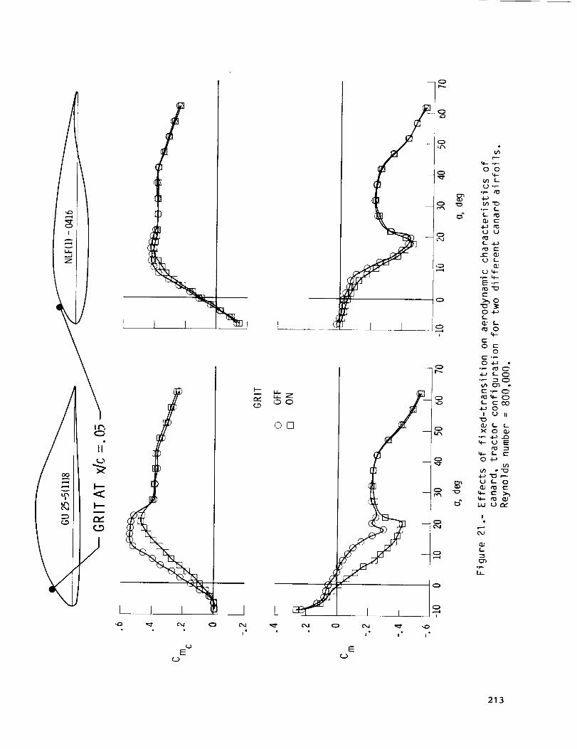
airfoils. Presented in figure 20 are
the results of some of the exploratory
tests to show the effect of Reynolds
number, and presented in figure 21 are
the effects of forced boundary-layer
transition using carborundum grit
applied at the 5-percent chord
station. The significant results of
figures 20 and 21 are that the
aerodynamic characteristics of the
NLF(1)-O_16 are not sensitive to
Reynolds number or forced boundary-
layer transition; whereas, the GU25-
5(11)8 airfoil shows loss of canard
llft due to boundary-layer separation
at low Reynolds number and, also, loss
of llft due to forced boundary-layer
transition. The NLF(1)-O416 airfoil
aerodynamic characteristics are typical
of several advanced NLF airfoils
developed in recent years which provide
promising performance gains.
Application of some of the advanced NLF
airfoils to conventional airplane
190

configurations for improved performancewill be addressed in subsequentsections.
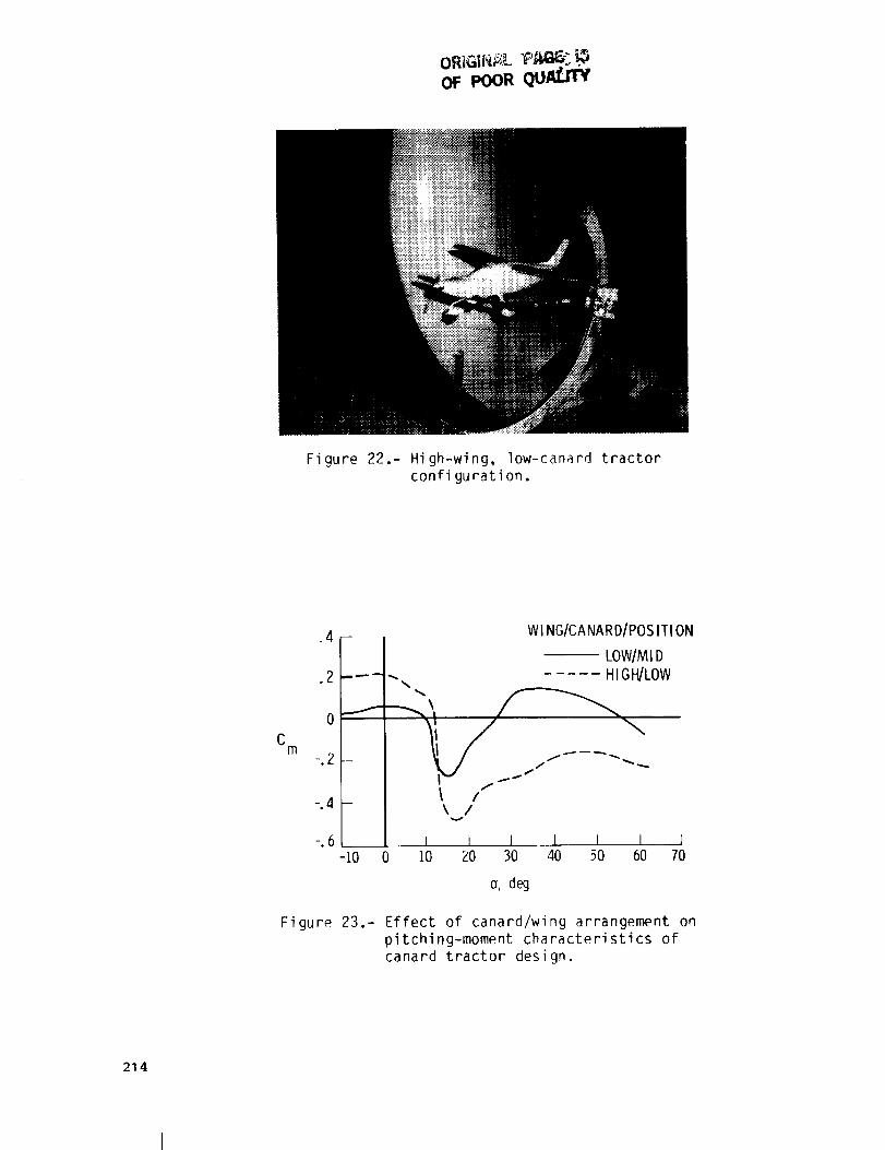
Included in the canard, tractorinvestigation were tests to study theeffect of relative locations of thecanard and wing on longitudinalcharacteristics of the configuration.Presented in figure 22 is a photographof the tractor model with the canardlowered on the fuselage and the wingraised to the top of the fuselage. Thedata of figure 23 show that modifyingthe configuration to have the canardlowered and the wing raised provided astabilizing influence on longitudinalstability in the post-stall angle-of-attack range and el[mlnated theundesirable deep-stall tendency of thebasic configuration with power on. The
stabilizing effect of the modified
design apparently results from moving
the canard out of the propeller
slipstream and moving the wing out of
the canard downwash.
Conventional Single-Englne
Tractor Design
The discussion of conventional
configurations will emphasize the use
of advanced NLF airfoils for improved
performance and the application of wing
leading-edge droop to the NLF airfoils
to improve stall/spin resistance with
minimum performance degradation.
Before discussing the new airfoil
configurations, a brief review of
related stall/spin research at Langley
is provided to discuss the development
of an effective wing leadlng-edge droop
for increased departure resistance.
Shown in figure 24 are the research
airplanes flown at Langley in the
stall/spin research program. These
research airplanes were flown with a
modified wing leading-edge droop which
proved effective for increased
stall/spin resistance. Figure 25 shows
some design features of the droop
arrangement developed for the T-tail
research airplane. An important
feature of the droop is the abrupt
discontinuity of the droop inboard
leading-edge. This d_scontinulty is
effective in generating a vortex which
acts as an aerodynamic fence to stop
the spanwise flow from the inboard
portion of the wing as stall
progresses. The leading-edge droop
extends to near the wing tip such that
the outer position of the wing performs
as a low-aspect-ratio wing with a very
high stall angle of attack. Flow
visualization studies using fluorescent
oll provide an excellent means of
illustrating the effectiveness of the
leading-edge droop. Figure 26 presents
the results of oil flow studies and
shows the basic wing in a stalled
condition with a predominant outward
flow direction. The outboard droop is
shown to keep the outer wing panel flow
attached to _ = 35 °. A summary of the
effectiveness of the droop for spin
prevention is presented in figure 27
which shows that the leading-edge droop
significantly improved the spin
resistance of the research airplanes.
The recent trend in general
aviation airplane design toward the use
of NLF airfoils for improved
performance has led to an interest in
applying the wing leading-edge
technology developed in stall/spln
research to the new NLF airfoils. Two
NLF airfoils of current interest are
the NLF(1)-O215F and the NLF(1)-O414F
(see fig. 28). One approach recently
studied in exploratory research
programs at Langley was to use the
NLF(1)-O414F airfoil for enhanced
performance, and the NLF(1)-O215F
191
airfoil for the droop required forimproved spin resistance. A leading-edge droop was developed from theNLF(1)-O215Fairfoil by gloving overthe leading-edge outboard panel of thewing. Presented in figure 29 is asketch of the advanced wing planform,comparedto the planform of a moreconventional general aviation wing.The advanced wing is of higher aspectratio, and the droop is smaller in spanand located further outboard than thatderived for conventional wings inearlier research. The droop wasdeveloped in subscale tests in theLangley 12-Foot Low-SpeedWindTunnelusing a wing-tlp balance to measuretheaerodynamics of the outer wing panel.This research also revealed that theeffectiveness of the outboard droopcould be enhancedby the addition of asmall-span inboard droop locatedinboard on the wing. _ photograph ofthe model used in the 12-foot tunneltest is presented in figure 30. Thefinal droop geometry developed from thelow-speed tests evolved from a numberof exploratory studies of differentdesigns. The fact that the mosteffective location of the droop wasrelatively far outboard on the wing isprobably related to the stall patternof the higher aspect ratio wingcomparedto that of previous wingsinvestigated. Someoil flow studiesconducted by Professor Allen Winkelmanat the University of Maryland haveshownthat considerable differencesoccur in the stall behavior of wings ofvarious aspect ratios. For example,presented in figure 31 are results ofoil flow studies which show that inseparated flow conditions the higheraspect ratio wings tend to have agreater numberof stall cells on thewing t,ailing edge than noted for thelower aspect ratio wings. These dif-ferences in surface patterns between
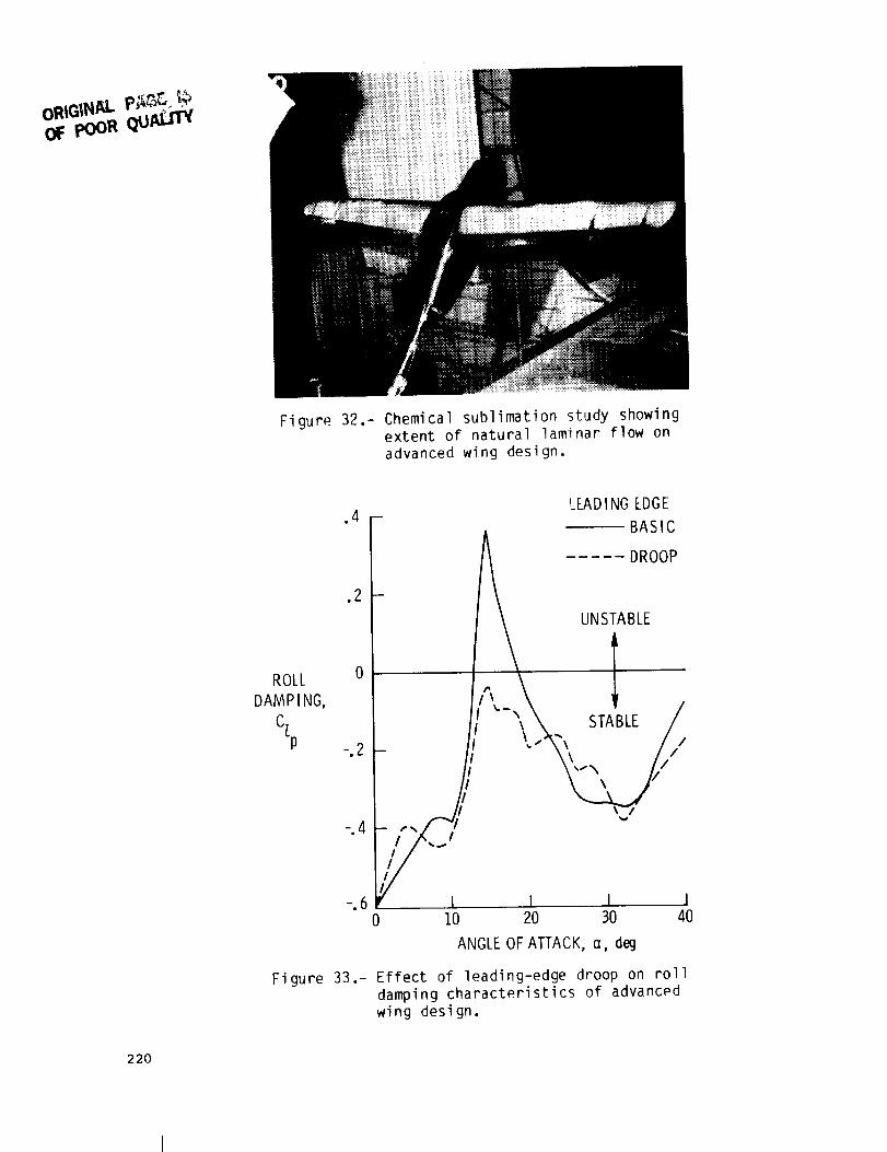
wings oF different aspect ratio maybeone of the reasons for differentleading-edge droop requirements as thewing aspect ratio increases.Additional tests are planned to provideresearch information for use in wingleading-edge droop design for theadvanced wing planform. Presented infigure 32 are the results of chemicalsublimation tests conducted on a largerscale model of the general aviationadvanced wing configuration. Figure 32shows that the wing had NLFback toabout 70-percent chord where transitionoccurred near the point of minimumpressure. Except for wedgesalong theedges of the droop, NLFalso occurredbehind the droop to the 70-percentchord station. Chemical sublimationtests on the lower side of the wingalso showedNLF to about the 70-percentchord station. Thus, incorporation ofthe droop had a minimal impact on thecharacter of the NLFfeatures of theadvancedwing.
The results of roll damping testson the advanced wing, presented infigure 33, show that the leading-edgedroop arrangement investigatedeliminated the unstable roll damping atthe stall for the basic wing andprovided stable roll damping for themodified wing over the test angle-of-attack range.
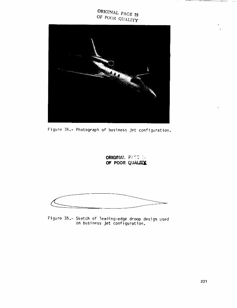
Conventional Business Jet Design
Another configuration employing NLFairfoils for improved performance isthe business jet shownin figure 34.The wing NLF airfoil used on theconfiguration is shownin figure 35.This airfoil is the NLF(1)-O414Fandhas the departure resistant leading-edge droop developed from the NLF(1)-O215Fin a similar manner to that
192
discussed earlier for the advanced NLFwing on the general aviation researchaircraft.
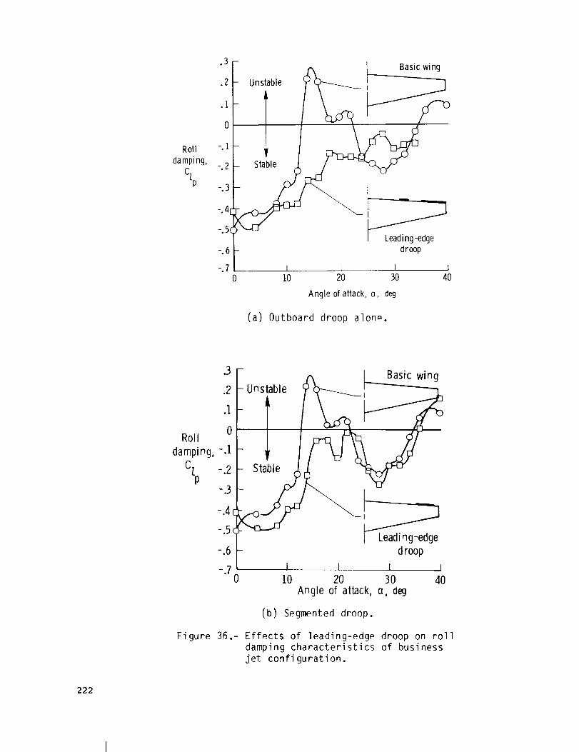
In order to determine theeffectiveness of the wing leadlng-edgedroop for departure resistance,damping-ln-roll tests were madeof thebusiness jet configuration, and theresults of the tests are presented infigure 36. The data of figure 36(a)show that the damping-in-rollcharacteristics of the basic wingbecameunstable near the stall angle ofattack, and as the angle of attackincreased, a region of stable dampingdeveloped and then the damping becameunstable again near _ = 35 ° . The
addition of the outboard droop is shown
to have eliminated the unstable damping
near the stall. Although the
configuration was not very heavily
damped in the stall angle-of-attack
range, the configuration would be
expected to show increased departure
resistance over that of the basic
design. In an attempt to increase the
roll damping of the configuration at
the initial stall angle of attack, the
basic leading-edge droop arrangement
was modified to add a small inboard
droop segment in combination with the
outboard segment (see fig. 36(b)).
This segmented droop arrangement was
developed for the general aviation
research configuration discussed in the
preceding section. The data of figure
36(b) show that the modified droop
arrangement provided a substantial
increase in roll damping at the initial
wing stall and provided good roll
damping over the test angle-of-attack
range. Figure 37 shows the results of
chemical sublimation tests of the wing
and modified leading-edge droop
arrangement. The results show that NLF
was maintained relatively far rearward
on the wing chord (about 70-percent
chord) and was not adversely affected
by the wing leading-edge droop.
Similar results were obtained for
sublimation tests made on the bottom of
the wing, indicating that performance
penalties associated with the departure
resistant wing should be small.
Three-Surface Configuration
Three-surface configurations
employing NLF airfoils were recently
investigated in exploratory studies at
the Langley Research Center. Figure 38
shows plan views of the three-surface
designs investigated and also a plan
view of a conventional design tested to
provide data for comparison purposes.
Included in the study were
configurations with aft-mounted engines
and with wing-mounted pusher engines.
All three configurations were derived
from the basic model components. The
model was equipped with a six-component
straln-gage balance for measuring the
total aerodynamic characteristics of
the configuration and also had separate
balances on the wing, canard, and the
engine nacelle. More complete model
descriptions are presented in reference
10. A photograph showing the model
with aft-mounted engines is presented
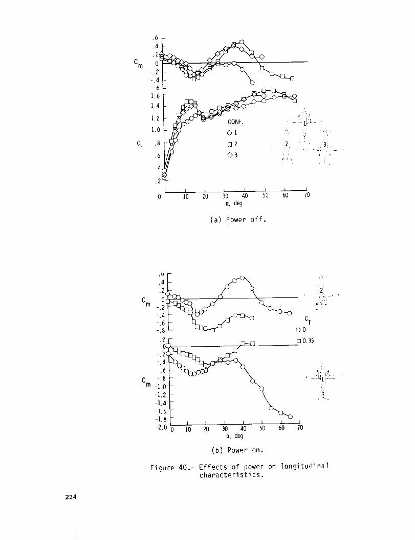
in figure 39. A comparison of the
aerodynamic characteristics of the aft-
mounted engine configurations with
those of the conventional design is
shown in figure 40. The llft data of
figure 40(a) show a slightly higher
llft-curve slope and maximum lift
coefficient for the three-surface
designs than for the conventional
design. This result can be attributed
to the lift of the canard and also to
the fact that wlng-nacelle interference
effects of the conventional design were
eliminated or minimized in the aft-
mounted engine configurations.
193

The data of figure 40(b) show the
effects of power on the longitudinal
stability characteristics of the test
configurations. Although all three
configurations exhibited a pitch-up
tendency, which Is generally
characteristic of a T-tall design, the
three-surface configuration tended to
have more aggravated pitch-up
characteristics. This result can be
attributed to the aft location of the
wing in the three-surface design, which
results in the wlng giving relatively
large destabilizing pitching-moment
changes when the wing stalls. The data
of figure 40(b) show a destabilizing
effect of power on the longitudinal
stability characteristics of the
conventional design, whereas a
significant stabilizing change in
pitching moment due to power is shown
for the three-surface configuration
with aft-fuselage-mounted engines.
Lateral-directional stability tests in
sideslip showed that power effects were
also very stabilizing characteristics
for the aft-mounted engine arrangement.
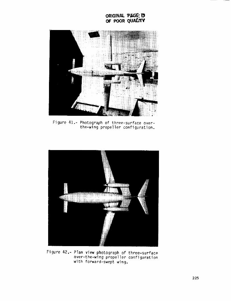
Over-the-Wing Propeller Design
Presented in figure 41 is a
photograph of an advanced configuration
recently investigated which uses the
propellers in an over-the-wing
arrangement to induce large favorable
interference effects of the propeller
slipstream on the wlng for reduced wing
drag at high power settings (see ref.
10). This concept, which is based on
earlier research with jet-englne
aircraft, was derived from the three-
surface design shown in figure 38 by
rotating the engine nacelles and
propellers from the pusher arrangement
to the over-the-wing tractor
arrangement. The drag data obtained
with the over-the-wing propeller
arrangement show that the drag of the
wing decreases as the propeller thrust
coefficient is increased. At the
thrust coefficient corresponding to the
climb condltlon, the drag of the wing
relative to that for the power-off
condition is significantly reduced.
Preliminary results of tests to measure
the effects of the wing proximity on
the propeller efficiency indicated
relatively small interference penalties
on the propeller performance.
Additional tests with the over-the-
wing propeller arrangement are
currently planned using a forward-swept
arrangement (fig. 42). The forward-
swept wlng configuration has the
advantage of locating the wing root
chord and over-the-wing propellers aft
on the fuselage for improved structural
efficiency and reduced cabin noise.
Preliminary results wlth the forward-
swept wing configuration indicate simi-
lar performance improvements for the
over-the-wlng propeller concepts to
those determined earlier for straight-
wing configurations. Preliminary
stability and control studies indicate,
however, that careful consideration
must be given to tailoring of the
forward-swept wlng design to minimlze
pltch-up tendencies associated with
early wing root stall and lateral
instability (loss of effective
dihedral) inherent wlth forward-swept
wings. Follow-on tests at larger scale
are planned to provide information for
analysis and evaluation of over-the-
wlng propeller concept and forward-
swept wing design at higher Reynolds
numbers.
CONCLUDING HEMARKS
The results of recent aerodynamic
research on advanced configurations
"#94
have revealed some important design 2.considerations that affect aerodynamicefficiency and performance, stabilityand control, and safety of flight.Moderncomposite manufacturing methodshave provided large regions of NLFboundary-layer behavior and stimulated 3.interest in developing advanced NLFairfoils and improved aircraftdesign. Experiments have indicatedthat selection of canard airfoils canbe extremely important to avoid largepitch trim and stability changesbetween conditions of natural and 4.forced turbulent boundary-layertransition; the canard airfoilcharacteristics at stall/post-stallangles of attack can determine thesusceptibility of an aircraft to pitch-up and deep-stall trim problems. Flow_ ' 5.field interactions between aircraftcomponentswere shown to produceundesirable aerodynamic effects on awing located behind a heavily loadedcanard. The use of properly designedwing leading-edge modifications, such 6.as a leadlng-edge droop, was found todelay wing stall and provide increasedstall/spin resistance with minimumperformance degradation. Power effectswere shownto be generally stabilizingfor aft-mounted engine arrangements anddestabilizing for tractor-engine 7.arrangements.
REFERENCES
I. Holmes, Bruce J.; Obara, Clifford 8.J.; and Yip, Long P.: NaturalLaminar Flow Experiments onModernAirplane Surfaces. NASATP-2256, June 1984.
Holmes, B. J.; and Obara, C. J.:Observations and Implications ofNatural Laminar Flow onPractical Airplane Surfaces.ICAS Paper 82-5.1.1, 1982.
Rutan, B.: Developmentof a Small,High Aspect Ratio CanardAircraft. Society ofExperimental Test PilotsTechnical Review, Vol. 13,No. 2, 1976, pp. 93-I01.
Yip, L. P.; and Coy, P. F.: WindTunnel Investigation of a Full-Scale Canard-Conflgured GeneralAviation Aircraft. ICAS PaperNo. 82-6.8.2, 1982.
Yip, Long P.: Wind-TunnelInvestigation of a Full-ScaleCanard-Conflgured GeneralAviation Airplane. NASATP'2382, 1985.
Chambers,Joseph R.; Ylp, Long P.;and Moul, ThomasM.: WindTunnel Investigation of anAdvancedGeneral Aviation CanardConfiguration. NASATM-85760,April 1984.
Somers, Dan M.: Design andExperimental Results for aNatural-Laminar-Flow Airfoil forGeneral Aviation Applications.NASATP-1861, 1981.
Viken, Jeffrey K.: AerodynamicDesign Considerations andTheoretical Results for a HighReynolds NumberNatural LaminarFlow Airfoil. M.S. Thesis,GeorgeWashington University,January 1983.
195
o Staff of the Langley Research
Center: Exploratory Study of
the Effects of Wing Leading-Edge
Modifications on the Stall/Spin
Behavior of a Light General
Aviation Airplane. NASA
TP-1589, 1979.
10. Johnson, J. L., Jr.; and White, E.
R.: Exploratory Low-Speed Wind-
Tunnel Investigation of Advanced
Commuter Conflgurations
Including an Over-the-Wing
Propeller Design. AIAA Paper
83-2531, October 1983.
11. Williams, L. J.; Johnson, J. L.,
Jr.; and Yip, L. P.: Some
Aerodynamic Considerations for
Advanced Aircraft
Configurations. AIAA Paper
84-0562, 1984.
12. Shortal, Joseph. A.; and Maggin,
Bernard.: Effect of Sweepback
and Aspect Ratio on Longitudinal
Stability Characteristics of
Wings at Low Speeds. NACA
TN-IO93, 1946.
196
OR_NAL PN_ _ rS_ F_X__.n_
Figure I.- Learjet/Piaggio GP-180.
Figure 2.- Beechcraft Starship 1, 85-percent-scale flying prototype.
197

iiiii!iiii!!!i
Figure 3.- Canard, single-engine pusherconfiguration in the Langley 30- by60-Foot Wind Tunnel.
ORIGINAL PAGE IS
OF POOR QUALITY
198

or POoRQu_
(a) Top vi ew
{._OUNPA,_Y I A_';, i:{ ; 14Af,., ::I'_I(}N
t i ¸
of wing and canard. (b) Canard.
Figure
/_ _i_i-' k_ i? _ _
(c) Winglet.
4.- Flow visualization using sublimating chemicalsto show boundary-layer transition.
199

(a) Rutan Vari-eze.
(b) Rutan Long-E_.
Figure 5.- Canard, single-engine pusher airplanes usedfor natural laminar flow flight experiments.
2OO
ORIGINAL PAGE I$
POOR QUALITY.

(c) Canard.
Figure 5.- Concluded.
SPRAY NOZZLES
j!
_._ il SURVEY CARRIAGE ARM
Figure 6.- Sketch of rain-simulation apparatus.
201
8r
6
C 4m
¢
'21 S0 i
4
[] FIXED, x/c = 005, WATEROFFOFREE, WATERON
CL 3C
.2
.I
0-8 -4 0 4
L ; I i L .____ I i J I
8 12 16 20 24 28 32 36 40
o deg
(a) Lift and pitching moments.
4
.3
CL
C 2
.I
0
CANARD TRANSITION
© FREE
[] FIXED, 5% CHORD, WATER OFF_> FREE, WATER ON
• 01 .02 .03 .04 .05 .06 .07
CDC
(b) Drag characteristics.
Figure 7.- Effect of water spray on canard aerodynamics.
202

Cm
C[
CLC
.2
-.2
-,6
1.8
1.6-
1.4-
1.2
1.0_
.8 -
.6 -
I
I
L L. L L L_ _ i L_ J •
.2-
OU
}
-8 -4 0 4 8 12 16 20 24 28
a, deg
/,W TRANSITION_
y
[] FIXED, 5°1oCHORD
- D E)
L__ i J I
32 36 40 44
(a) Lift and pitching moments.
Figure 8.- Effect of canard transition on airplane
aerodynamics.
203
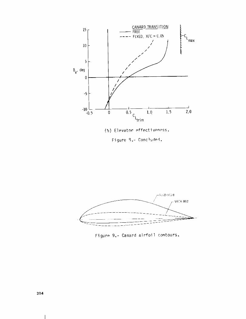
15
5
6e, deg
0
-5
-10 - /-0.5 0
(b)
CANARDTRANSITIONFREE
.... FIXE0, X/C : 0,05
/I/11111 /
///
/1 _. _ i I
0.5 ].0 ].5 2.0
CLtrim
Elevator effectivpn_ss.
Figure 8.- Concluded.
-CLmax
Figure 9.- Canard airfoil contours.
204

0,4 -
Cm 0
-0.4-10
NACA 0012
(6e = I0°)---_
I I I I I
0 I0 20 30 40 50o, deg
(a) Total pitching-moment characteristics.
2.0 --
1.5
CL 1.0
.5 -
0-I0
/
Airfoil section"""
= 0°)
..... NACA0012(be = 10°)
I I I I I0 10 20 30 40 50
(I, deg
(b) Canard lift characteristics.
Figure I0.- Effect of canard on longitudinal stabilityof configuration with aft c.g.:
Reynolds number = 1.60 million.
205

Figure 11.- Sketch oF canard-wing aerodynamicflow interactions.
206
I0
8-
n.4-
0
CANARD TiP LOCATION,II --/-Y= 0.535I b/2 CANARD
O" --'0""-i[0.". OOFFE]ON
-_3""-_- -::i_50
I "_III
a = 1.5°
-.2 i _ i I J
0 .2 .4 y .6 .8 1.0
b/2
Fi gu re 12.- Effect of canard on spanloaddistribution of wings,
LEADING-EDGE DROOP
ORiGiNALOF POOR
ON
(a) Tuft flow visualization.
Figure 13.- Effect of leading edge on w_ngstall patterns, _ = 19.5 °.
207
O0 ft
BL 128
/
/
//
/
.J
(b) Leading-edge droop.
Figure 13.- Concluded.
fl
BL 99.5
12
10
8
ASPECTRATIO 6
4
A.%S,NG.EENO,NEPUSH .UNSTABLEPITCH
BREAK AT STALL
STABLEPITCH jr" _ aBREAKAT STALL
- Cm _ _o
I I I i I10 20 30 40 50
WING SVVEEP,deg
Figure 14.- Effect of wing aspect ratio and sweep onpitching-moment characteristics at stall.
208
4_
Cm0L
[
.2 i
-.4Fl
-.6J- ± k
1.8
1.6
12CL
I OFI
.8 F
iI
6[
20T-
r1.4 i
LI
/ _ o_F
.4l / _ oN
i
i
I
[- . 1 _
-8 4 0 4 8 12 16 20 24 28 32 36 40 44
a, deg
Figure 15.- Effect of leading-edge droop onlongitudinal characteristics.
,2 - _ UNS BLE
-° 4 --
-, 6 --
-.8 I-5 0 5 I0 15 20 25 30 35 40
., deg
Effect of leading-edge droop on rolldamping characteristics.
2
CL 0C
-.2
-.4
ROLL
DAMPI NG,
C/.p
Figure 16.-
209

Figure 17.- Canard, tractor configuration mounted
in the 30- by 60-Foot Wind Tunnel.
I Fp A Fc
Fp
!
210
Tractor design
• Destabilizing effect
Pusher design
• Stabilizing effect
(a) Illustration of power effects.
C m
.2 F- _l /.----_...
-'2I-. 6 _ _t___
0 10 20 30 40 50
[_X CT
- \\\ Power off
\k 0 4
,
.._L L_ 1_
0 i0 20 30 40 50
o, deg Q, deg
(b) Pitching-moment characteristics.
Figure 18.- Comparison of powpr effects on
pitching-moment characteristics of
canard tractor and pusher designs.

Cm
-.2 --
-° 4, --
-10
CANARD AIRFOIL
NACA 23018
GU 25 - 5(11)8
NLF(1] - 0416
I I I I I J10 20 30 40 50 60
a, deg
Figure 19.- Effect of canard airfoil on
pitching-moment characteristics.
211

//
I
._.J
z
\
//
/
/I
C
J
/
I____l I
/
I
....3
I
I
0
I
I I
0
0
0
0
I
E
• • °! ! !
L
E
r_
212
/
/
I I
E
C)
• . oI I I
213
OF POOR
Figure 22.- High-wing, low-canard tractorconfiguration.
4-
.2 m_-
J0
Cm
-.4 -
-° 6
-I0
Figure 23.-
WI NG/CANARD/POSITI ON
-- LOW/MIDHIGH/LOW
\._./
i i ] l I I i0 i0 20 30 40 50 60 70
a, deg
Effect of canard/wing arrangement onpitching-moment characteristics ofcanard tractor design.
214

Poc_ Quarry
HIGH-cx RESEARCH AIRPLANESConventional conf ms
Figure 24.- Conventional airplanes used install/spin research.
215

IPED LEADING EDGE
SHARP DISCONTINUITY
,_"' b = WING SPAN '_
j _.AIRFOIL SECTION AT 0.5]' b/2
-F' \ ,_AI,FOl,SECTIONAT0.%b/Z
\
Figure 25.- Wing leading-edge droop used install/spin research.
ORIGINAL PAGE IS
OF_ POOR QUALITY
216

oF POoRQuActrv
e = 30 °
(a) Basic wing, a = 30 ° .
= 35 °
(b) Modified wing, _ = 35 ° .
Figure 26.- 0il flow visualization on tapered-wingmodel showing effect of leading-edgedroop.
AA-IX (YANKEE)
NUMBEROF SPINS
MODIFIEDAIRPLANE
ATTEMPTS
BASICAI RPLANE
185--: 969o193
127- 98%
129
224-- = 88%255
0_=0%
31
C-23X (SUNDOWNER)
12PA-28RX (ARROW) 23--6" 5%
Figure 27.- Summary of stall/spin flight testresults showing spin resistance due towing modifications.
217

NIF(1)-0215 F (SOMERS)
NLF (1) - 0414 F (HARVEY/VI KEN)
Figure 28.- Sketch of two different airfoilsdesigned for natural laminar flow.
C,
II L ....
r'------q t
• Drooped L.E. extension 1 f NLF airfoil for
for stall/spin resistance I drag reductionf
I If
Ii
Figure 29.- Leading-edge droop modificationapplied to advanced wing design.
218

OF POOR QUALITY
Figure 30.- Photograph of leading-edge droop onadvanced wing design in Langl_y12-Foot Low-Speed Wind Tunnel.
Figure 31.- Oil flow patterns developed on aseries of wings (14% Clark Y airfoilsof various aspect ratios, _ = 18.4 °,Reynolds number = 385,000.
219
oRIGINJ_Lp_E. t_oi: i>ooI___
Figure 32.- Chemical sublimation study showingextent of natural laminar flow onadvanced wing design.
ROLL
DAMPING,
C[P
Figure
.4
.2
0
-.2
-.4
-.6
33.-
LEADING EDGE
BASIC
..... DROOP
UNSTABLE
//
/
I ! I0 10 20 30 40
ANGLE OF ATTACK, a, d_
Effect of leading-edge droop on rolldamping characteristics of advancedwing design.
220
ORIGINAL PAGE IS
OF POOR QUALITY"
Figure 34.- Photograph of business jet configuration.
ORIGINAL ?;:z: _:_OF POOR QU_
Figure 35.- Sketch of leading-edge droop design usedon business jet configuration.
221
Rolldamping,
C[P
Unstable
Stable
droop
I I I J0 10 20 30 40
Angle of attack, o, deg
(a) Outboard droop alone.
.3
.2
.I
0Roll
damping, -.1
C[ -.2P
-,3
-.41
-°5 _
-°6
-,7
Un,ab,e- Stable
droop
I 1 1 I0 10 20 30 40
Angle of attack, a, deg
(b) Segmented droop.
Figure 36.- Effects of leading-edge droop on rolldamping characteristics of business
jet configuration.
222
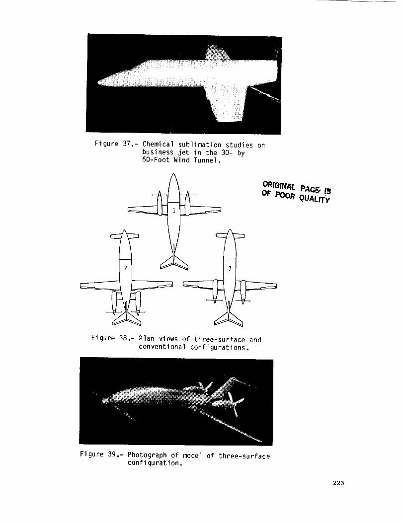
Figure 37.- Chemical sublimation studies onbusiness jet in the 30- by60-Foot Wind Tunnel,
/_ ORIGINAl.. PAC_ l_
Figure 38.- Plan views of three-surface and
conventional configurations.
Figure 39.- Photograph of model of three-surfaceconfiguration.
223
Cm 0-.2
-.4
-,6
1,6
1.4
1.2
1.0
CL .8
.6
.6 -
.2
C___ _; i''_' 'I
.4
I I I 1
.2
0 I0 20 30 40 50 60 70a, deg
(a) Power off.
.6-
.2(
OtCm -.2
-.4
-.6
-.8
.20 • _ -
-.2
-.46-18
Cm -i.0
q.2
-I.4
-1.6q.8
-2.0 0 10 20 30 40 50 60
a, deg
(b) Power on.
CT
O0
O0.35
IlO
, I
l_?:,--'_._..'_
Figure 40.- Effects of power on longitudinalcharacteristics.
224
ORIGINAL _J_'A_OF POOR " " "
Fi gu re 41.- Photograph of three-surface over-the-wing propeller configuration.
Figure 42.- Plan view photograph of three-surfaceover-the-wing propeller configurationwith forward-swept wing.
225