
N57EN POH - Eric Newton's Bearhawk Sitemybearhawk.com/BH682POH.doc · Web viewNew C/N oil pump...
80
N57EN SERIAL #682 PILOT’S OPERATING HANDBOOK
Transcript of N57EN POH - Eric Newton's Bearhawk Sitemybearhawk.com/BH682POH.doc · Web viewNew C/N oil pump...

N57ENSERIAL #682
PILOT’S OPERATING HANDBOOK

BEARHAWK – N57EN SERIAL #682 SECTION 1 GENERAL
THIS PAGE
INTENTIONALLY
LEFT BLANK
1-2

BEARHAWK – N57EN SERIAL #682 SECTION 1 GENERAL
SECTION 1
GENERALThree View......................................................................1-2Introduction.....................................................................1-1Descriptive Data..............................................................1-1
Engine.......................................................................1-1Propeller...................................................................1-1Fuel...........................................................................1-1Oil.............................................................................1-3Maximum Weights...................................................1-3Standard Weights.....................................................1-3Cabin and Entry Dimensions....................................1-3
Baggage Space and Entry Dimensions.....................1-3Specific Loadings.....................................................1-3
Symbols, Abbreviations and Terminology......................1-3General Airspeed Terminology Symbols.................1-3Meteorological Terminology....................................1-4Engine Power Terminology......................................1-4Airplane Performance and Flight Planning Terminology.............................................................1-4Weight and Balance Terminology............................1-4
INTRODUCTION
This handbook contains 7 sections, and includes material corresponding to that required to be furnished to the pilot by 14 CFR. It also contains supplemental data applicable to this aircraft, including a suggested checklist for annual condition inspections.
Section 1 provides basic data and information of general interest. It also contains definitions or explanations of symbols, abbreviations, and terminology commonly used.
DESCRIPTIVE DATA
Engine
Number of Engines: 1Engine Manufacturer: Lycoming/Barrows Engine Model Number: O-360 EXPEngine Serial Number: L-5505-39Engine Type: Normally aspirated, direct-drive, air-cooled,
horizontally-opposed, carburetor-equipped, four-cylinder engine with 360 cubic inch displacement
Horsepower Rating and Engine Speed: 180 rated BHP at 2700 RPM
Compression Ratio: 8.2:1
Note
A&P Bob Barrows, phone number (540) 473-3661, built the engine. The engine was built from Lycoming parts to 0 SMOH, or new tolerance limits as per the Lycoming Overhaul manual. Yellow tagged and overhauled solid crankshaft, connecting rods, crankcase; cam and lifter bodies were used. New bearings were used. New Lycoming (74158) chrome angle valve cylinder assemblies (pistons machined to 8.2:1 compression ratio) with new steel rings were installed.
New C/N oil pump gears, new seals and gaskets, new plugs, overhauled MA4-5 carburetor and overhauled magnetos with a new wiring harness.
The engine was built with a compression ratio of 8:2:1 and is STC’d for 93 Octane unleaded auto fuel. 110LL aviation fuel is also acceptable and it is recommended that the engine be run with 100LL periodically. PropellerPropeller Manufacturer: SensenichPropeller Model Number: M76-EMS-0-56Propeller Serial Number: 39591Number of Blades: 2Propeller Type: Fixed Pitch Aluminum Propeller Diameter: 76” Pitch: 56 degrees
Fuel
Approved Fuel Grades:93 Octane unleaded auto fuel (no Ethanol)100LL grade aviation fuel
Fuel Capacity: Total Capacity: 52 gallonsTotal Capacity Each Tank: 26 gallonsTotal Usable: 51 gallons
NoteTo ensure maximum fuel capacity when refueling, place the fuel selector valve in OFF, LEFT, or RIGHT position to prevent cross feeding.
1-3

Wing Span 33 ft 2 inLength 23 ft 6 inHeight (at cabin) 6 ft 9 inWing Reference Area 180 ft2

Oil
Oil Grade (Specification):Aeroshell 100W or Aeroshell 15W50 orEquivalent aviation grade oil
Oil Capacity:Sump: 8 U.S. QuartsTotal: 8 U.S. QuartsMinimum Safe Quantity in Sump: 2 U.S. Quarts
The Oil Dipstick is marked in 2-quart increments starting at 2 quarts (the minimum) and ending at 8 quarts (the maximum).
Maximum Weights
Takeoff: 2700 lbsLanding: 2500 lbs
Standard Weights
Standard Empty Weight: 1338 lbs.Maximum Useful Load: 1162 lbs
Cabin and Entry Dimensions
Detailed dimensions of the cabin interior and entry door opening instructions are illustrated in Section 6.
Specific Loadings
Wing Loading: 13.89 lb/ft2 at 2500 lbs (15 lb/ft2 at 2700 lbs)
Power Loading: 9.61 lb/HP at 2500 lbs(10.38 lb/HP at 2700 lbs)
Limit Load Factor
Maximum 4.5 G’s @ 2,500 lbsMaximum 5.0 G’s @ 2,300 lbs.
Symbols, abbreviations and terminologyGeneral Airspeed Terminology Symbols
KCAS Knots Calibrated Airspeed is indicated airspeed corrected for position and instrument error and expressed in knots. Knots calibrated airspeed is equal to KTAS in standard atmosphere at sea level.
MPH Knots Indicated Airspeed is the speed shown on the airspeed indicator and expressed in knots.
KTAS Knots True Airspeed is the airspeed expressed in knots relative to undisturbed air, which is KCAS, corrected for altitude and temperature.
VA Maneuvering Speed is the maximum speed at which you may use abrupt control travel.
VFE Maximum Flap Extended Speed is the highest speed permissible with wing flaps in a prescribed extended position.
VNO Maximum Structural Cruising Speed is the speed that should not be exceeded except in smooth air, then only with caution.
VNE Never Exceed Speed is the speed limit that may not be exceeded at any time.
VS Stalling Speed or the minimum steady flight speed at which the airplane is controllable.
VS0 Stalling Speed or the minimum steady flight speed at which the airplane is controllable in the landing configuration at the most forward center of gravity.
VX Best Angle-of-Climb Speed is the speed, which results in the greatest gain of altitude in a given horizontal distance.
VY Best Rate-of-Climb Speed is the speed, which results in the greatest gain in altitude in a given time.

Meteorological Terminology
OAT Outside Air Temperature is the free air static temperature. It is expressed in either degrees Celsius or degrees Fahrenheit.
Standard Temperature
Standard Temperature is 15°C at sea level pressure altitude and decreases by 2°C for each 1000 feet of altitude.
Pressure Altitude
Pressure Altitude is the altitude read from an altimeter when the altimeter’s barometric scale has been set to 29.92 inches of mercury (1013 mb).
Engine Power Terminology
BHP Brake Horsepower is the power developed by the engine.
RPM Revolutions Per Minute is engine speed.
MAP Manifold Air Pressure is a pressure measured in the engine’s induction system and is expressed in inches of mercury (Hg).
Airplane Performance and Flight Planning Terminology
Demon-strated Crosswind Velocity
Demonstrated Crosswind Velocity is the velocity of the crosswind component for which adequate control of the airplane during takeoff and landing was actually demonstrated during flight tests. The value shown is not considered to be limiting.
Usable Fuel
Usable Fuel is the fuel available for flight planning.
Unusable Fuel
Unusable Fuel is the quantity of fuel that cannot be safely used in flight.
GPH Gallons Per Hour is the amount of fuel (in gallons) consumed per hour.
NMPG Nautical Miles Per Gallon is the distance (in nautical miles), which can be expected per gallon of fuel consumed at a specific engine power setting and/or flight configuration.
g g is acceleration due to gravity.
Weight and Balance Terminology
Reference Datum
Reference Datum is an imaginary vertical plane from which all horizontal distances are measured for balance purposes.
Station Station is a location along the airplane fuselage given in terms of the distance from the reference datum.
Arm Arm is the horizontal distance from the reference datum to the center of gravity (C. G.) of an item.
Moment Moment is the product of the weight of an item multiplied by its arm.
Center of Gravity (C. G.)
Center of Gravity is the point at which an airplane, or equipment, would balance if suspended. Its distance from the reference datum is found by dividing the total moment by the total weight of the airplane.
C. G. Arm Center of Gravity Arm is the arm obtained by adding the airplane’s individual moments and dividing the sum by the total weight.
C. G. Limits
Center of Gravity Limits are the extreme center of gravity locations within which the airplane must be operated at a given weight.
Standard Empty Weight
Standard Empty Weight is the weight of a standard airplane, including unusable fuel, full operating fluids and full engine oil.
Basic Empty Weight
Basic Empty Weight is the standard empty weight plus the weight of optional equipment.
Zero Fuel Weight
Zero Fuel Weight is the difference between gross weight of the airplane and the fuel weight.
Useful Load
Useful Load is the difference between takeoff weight and the basic empty weight.
Gross (Loaded) Weight
Gross (Loaded) Weight is the loaded weight of the airplane.
Maximum Takeoff Weight
Maximum Takeoff Weight is the maximum weight approved for the start of the takeoff run.
Maximum Landing Weight
Maximum Landing Weight is the maximum weight approved for the landing touchdown.
Tare Tare is the weight of chocks, blocks, stands, etc. used when weighing an airplane, and is included in the scale readings. Tare is deducted from the scale reading to obtain the actual (net) airplane weight.

BEARHAWK – N57EN SERIAL #682 SECTION 2
LIMITATIONS
SECTION 2
LIMITATIONSIntroduction.....................................................................2-1Airspeed Limitations.......................................................2-1Airspeed Indicator Markings...........................................2-1Power Plant Limitations..................................................2-1Weight Limits..................................................................2-2Center of Gravity Limits..................................................2-2
Maneuver Limits..............................................................2-2Flight Load Factor Limits................................................2-2Kinds of Operation Limits...............................................2-2Fuel Limitations...............................................................2-3Placards............................................................................2-3
2-1

INTRODUCTION
Section 2 includes operating limitations, instrument markings, and basic placards necessary for the safe operation of the airplane, its engine, systems and equipment.
AIRSPEED LIMITATIONS
Airspeed limitations and their operational significance are shown in figure 2-1.
AIRSPEED INDICATOR MARKINGS
Airspeed indicator markings and their color code significance are shown in figure 2-2.
2-2
SPEED (indicated airspeed) KNOTS MPH REMARKS
VNE
Never Exceed Speed 152 175 Do not exceed this speed in any operation
VNOMaximum Structural Cruising Speed 135 155 Do not exceed this speed except in smooth air, and
then only with caution
VAManeuvering Speed:
2700 Pounds2500 Pounds2300 Pounds2100 Pounds1900 Pounds
10096928884
11511010610196
Do not make full or abrupt control movements above this speed
VFEMaximum Flap Extended Speed:
15° Flaps25° Flaps40° Flaps50° Flaps
87746556
100857565
Do not exceed these speeds with the given flap settings
Figure 2-1. Airspeed Limitations
MARKING MPH-IAS VALUE OR RANGE SIGNIFICANCE
White Arc 45 - 65 Full Flap Operating Range. Lower limit is maximum weight VS0 in landing configuration. Upper limit is maximum speed permissible with flaps extended.
Green Arc45 - 155
Normal Operating Range. Lower limit is maximum weight VS at most forward C.G. with flaps retracted. Upper limit is maximum structural cruising speed.
Yellow Arc155 - 175
Operations must be conducted with caution and only in smooth air.
Red Line175
Maximum speed for all operations.
Figure 2-2. Airspeed Indicator Markings

POWER PLANT LIMITATIONS
Engine Manufacturer: Barrows LycomingEngine Model Number: O-360-EXPEngine Operating Limits for Takeoff and Continuous Operations:
Maximum Power: 180 BHPMaximum Engine Speed: 2700 RPMNever Exceed CHT: 500°FMaximum Recommended CHT: 435°FMaximum Oil Temperature: 235°FRecommended Oil Temperature: 170° - 180°FOil Pressure
Minimum: 60 psi @2000 RPMMaximum: 100 psi @2000 RPMIdling: minimum. 25 psiStart & Warm-Up: maximum 115 psi
Fuel PressureMinimum: 0.5 psiMaximum: 8 psi
Propeller Manufacturer: Sensenich Propeller Model Number: M76EMS-0-56Propeller Diameter: 76 inchesPropeller Pitch: 56 degrees
WEIGHT LIMITS
Maximum Takeoff Weight: 2700 lbsMaximum Landing Weight: 2500 lbs
Note:Refer to Section 6 of this handbook for loading arrangements with the rear seat removed for cargo accommodation.
CENTER OF GRAVITY LIMITS
Center of Gravity Range:Forward: 10.5 inches aft of datum (16 percent MAC)Aft: 22.5 inches aft of datum (34 percent MAC)
Reference Datum: Wing leading edge
Note:See section 5 for more on weight and balance calculations
MANEUVER LIMITS
This airplane is designed in the utility category. The utility category is applicable to aircraft intended for limited acrobatic operation. These operations include any maneuvers incident to normal flying, stalls (except whip stalls), spins, lazy eights, chandelles, and steep turns, or similar maneuvers, in which the angle of bank is not more than 60 degrees. (Ref 14 CFR § 23.3)
Load Limit Factor (“G” Limits)Maximum + 4.5 g at 2,500 lbs grossMaximum + 5.0 g at 2,300 lbs gross
KINDS OF OPERATION LIMITS
The airplane is equipped for day/night VFR operations. FAR Part 91 establishes the minimum required instrumentation and equipment for these operations.
Flight into known icing conditions is prohibited.
2-3

FUEL LIMITATIONS
Approved Fuel Grades (and Colors):93 Octane Auto Fuel (No Ethanol)100LL Grade Aviation Fuel (Blue)
Fuel Capacity: Total Capacity: 52 gallonsTotal Capacity Each Tank: 26 gallonsTotal Usable: 51 gallons
Note
To ensure maximum fuel capacity when refueling, place the fuel selector valve in either LEFT, RIGHT or OFF position to prevent cross-feeding.
Note
Takeoff and land with the fuel selector valve handle in the BOTH position.
PLACARDS
Near Dynon EFIS:
Flap Limit Speeds15° 100 MPH25° 85 MPH40° 75 MPH50° 65 MPHManeuvering Speed
110 MPH
In full view of all passengers:
PASSENGER WARNINGTHIS AIRCRAFT IS AMATEUR BUILT AND DOES NOT COMPLY WITH THE FEDERAL
SAFETY REGULATIONS FOR STANDARD AIRCRAFT
Near each entrance to the cabin
EXPERIMENTAL
2-4

BEARHAWK – N57EN SECTION 3S/N #682 EMERGENCY PROCEDURES
SECTION 3
EMERGENCY PROCEDURESIntroduction.....................................................................3-1Airspeeds For Emergency Operations.............................3-1Engine Failures................................................................3-2
Engine Failure During Takeoff Run.........................3-2Engine Failure Immediately After Takeoff..............3-2Engine Failure During Flight...................................3-2Starter Does Not Disengage.....................................3-2
Forced Landings..............................................................3-3Emergency Landing Without Engine Power............3-3Precautionary Landing With Engine Power.............3-3Ditching....................................................................3-3
Landing With A Flat Main Tire.......................................3-3Landing Without Elevator Control..................................3-3Rough Engine Operation Or Loss Of Power...................3-4
Carburetor Icing.......................................................3-4Spark Plug Fouling...................................................3-4Ignition Malfunction.................................................3-4Low Oil Pressure......................................................3-4
Fires.................................................................................3-4During Start On Ground...........................................3-4Engine Fire In Flight................................................3-5Electrical Fire In Flight............................................3-5Cabin Fire.................................................................3-5Wing Fire..................................................................3-5
Carbon Monoxide Warning.............................................3-5Electrical Power Supply System Malfunctions...............3-6
Over-Voltage Condition...........................................3-6Low Voltage Condition............................................3-6
Icing.................................................................................3-7Inadvertent Icing Encounter.....................................3-7Static Source Blockage (Erroneous Instrument
Reading Suspected)...........................................3-7Emergency Operation In Clouds
(Attitude Gyro Failure).............................................3-7Executing A 180° Turn In Clouds............................3-7Emergency Descent Through Clouds.......................3-8Recovery From A Spiral Dive..................................3-8
Spins................................................................................3-8
INTRODUCTION
Section 3 contains the procedures to be used in coping with the various emergencies that may be encountered. A thorough knowledge of these procedures will enable the crew to perform their emergency duties in an orderly manner, and to judge more quickly the seriousness of the emergency.
Regardless of specific emergency encountered:
1. Maintain airplane control2. Analyzed the situation3. Take coordinated corrective action4. Land as soon as practicable
AIRSPEEDS FOR EMERGENCY OPERATIONS (indicated airspeeds)
Engine Failure After Takeoff:Wing Flaps Up.................................................70 MPHWing Flaps Down 20°......................................65 MPH
Maneuvering Speed:2700 Pounds...................................................115 MPH2500 Pounds...................................................110 MPH2300 Pounds...................................................106 MPH2100 Pounds...................................................101 MPH1900 Pounds.....................................................96 MPH
Maximum Glide:2700 Pounds.....................................................75 MPH1900 Pounds.....................................................70 MPH
Precautionary Landing With Engine Power, Flaps 40°..........................................................60 MPH
Landing Without Engine Power:Wing Flaps Up.................................................65 MPHWing Flaps 40°.................................................60 MPH
3-1

BEARHAWK – N57EN SECTION 3S/N #682 EMERGENCY PROCEDURES
ENGINE FAILURES
Engine Failure During Takeoff Run
1. Throttle – IDLE
2. Brakes – As Required
3. Wing Flaps – Retract
Retracting Wing Flaps can improve braking effectiveness by reducing lift and thus increasing normal force on the wheels.
After tail wheel is on the runway:
4. Control stick – Full Aft
Full aft stick reduces the probability of nose-over during heavy braking.
If necessary to secure engine:
5. Mixture – IDLE CUT-OFF
6. Ignition Switches – OFF
7. Master Switch – OFF
If an engine failure occurs during the takeoff run, the most important thing to do is to stop the airplane on the remaining runway. The extra items on the checklist will provide added safety during a failure of this type.
Engine Failure Immediately After Takeoff
1. Pitch Down for Airspeed – 70 MPH
If landing is not immediately imminent, attempt an engine restart as detailed in Engine Failure During Flight.
As time allows:
2. Wing Flaps – As Required (50° recommended)
3. Mixture – IDLE CUT-OFF
4. Fuel Selector Valve – OFF
5. Ignition Switches – OFF
6. Master Switches – OFF
Prompt lowering of the nose to maintain airspeed and establish a glide attitude is the first response to an engine failure after takeoff. In most cases, the landing should be planned straight ahead with only small changes in
direction to avoid obstructions. Altitude and airspeed are seldom sufficient to execute a 180° gliding turn necessary to return to the runway.
WARNING
Do not allow securing the fuel and ignition systems to take precedence over properly flying, flaring, and landing the airplane.
Engine Failure During Flight
1. Carburetor Heat – ON
2. Fuel Selector Valve – LEFT/RIGHT/BOTH
3. Mixture – RICH
4. Ignition Switch – LEFT/RIGHT/BOTH
5. Starter – START (if propeller has stopped)
If restart is not successful, go to Emergency Landing Without Engine Power.
After an engine failure in flight, establish a descent at best glide speed. While gliding toward a suitable landing area, an effort should be made to identify the cause of the failure. If time permits, an engine restart should be attempted as shown in the checklist. If the engine cannot be restarted, a forced landing without power must be completed.
Starter Does Not Disengage
If STARTER ENGAGED light remains on after releasing the STARTER switch
1. Master Switch – OFF
2. Mixture – IDLE CUT-OFF
3. Ignition Switch – OFF
If the STARTER ENGAGED light remains on after the Starter Switch is released, the most likely cause is a stuck starter contactor. Turning off the Master Switch opens the master contactor, removing power from the starter motor, which will probably disengage the starter. The remaining steps shut down the engine for inspection and troubleshooting.
FORCED LANDINGS
Emergency Landing Without Engine Power
3-2

BEARHAWK – N57EN SECTION 3S/N #682 EMERGENCY PROCEDURES
1. Airspeed – 70 MPH (flaps UP)65 MPH (flaps DOWN)
2. Wing Flaps – As Required (50° recommended)
3. Mixture – IDLE CUT-OFF
4. Fuel Selector Valve – OFF
5. Ignition Switches – OFF
6. Master Switch – OFF
7. Windows – Unlatch prior to touchdown
8. Touchdown – 3-point attitude
9. Brakes – Apply heavily
Precautionary Landing With Engine Power
1. Wing Flaps – 25°
2. Airspeed – 70 MPH
3. Selected Field – Fly Over, noting terrain and obstructions then retract flaps upon reaching a safe altitude and airspeed
4. Wing Flaps – 40°
5. Airspeed – 65 MPH
6. Master Switch – OFF
7. Windows – Unlatch prior to touchdown
8. Touchdown – 3-point attitude
9. Ignition Switches – OFF
10. Brakes – Apply heavily
Ditching
1. Radio – MAYDAY on 121.5 MHz (or current ATC facility), giving location and intentions
2. Heavy Objects – Secure or Jettison
3. Seats and Belts – Secure
4. Approach – High Winds, Heavy Seas – Into the windLight Winds, Heavy Swells – Parallel to swells
5. Wing Flaps – 40°
6. Power – Establish 300 ft/min descent at 70 MPH
7. Windows – Unlatch
8. Touchdown – Level Attitude at 300 ft/min descent
9. Airplane – Evacuate
10. Life Vests and Raft – Inflate
LANDING WITH A FLAT MAIN TIRE
1. Wing Flaps – 40°
2. Touchdown – 3-point attitude
3. Aileron Control – Hold off flat tire as long as possible
4. Brakes – As required to maintain directional control
LANDING WITHOUT ELEVATOR CONTROL
Trim for horizontal flight with flaps 25° using an airspeed of approximately 75 MPH by using throttle and trim controls. Then do not change the trim setting, and control the glide angle by adjusting power exclusively.
At flare out, the trim should be adjusted nose up and power adjusted so that the airplane will rotate to a suitable attitude for touchdown. Close the throttle at touchdown.
3-3

BEARHAWK – N57EN SECTION 3S/N #682 EMERGENCY PROCEDURES
ROUGH ENGINE OPERATION OR LOSS OF POWER
Carburetor Icing
An unexplained drop in RPM and/or manifold pressure may result from the formation of carburetor ice. To clear the ice, apply full throttle and pull the carburetor heat knob full out until the engine runs smoothly; then remove carburetor heat and readjust the throttle.
If conditions require the continued use of carburetor heat in cruise flight, use the minimum amount of heat necessary to prevent ice from forming. Lean the mixture slightly for smoothest engine operation.
Spark Plug Fouling
A slight engine roughness in flight may be caused by one or more spark plugs becoming fouled by carbon or lead deposits. This may be verified by turning the key switch to LEFT, and then back to BOTH, then to RIGHT, then returning the key switch to BOTH. An obvious power loss in single ignition operation (LEFT OR RIGHT) is evidence of spark plug or ignition system trouble. The offending plug can be identified by the sudden drop in EGT on the EIS monitor.
Assuming that spark plugs are the more likely cause, lean the mixture to the recommended lean setting for cruising flight. If the problem does not clear up in several minutes, determine if a richer mixture setting will produce smoother operation. If not, proceed to the nearest airport for repairs with the key switch in the BOTH position unless extreme roughness dictates the use of a single ignition system (LEFT or RIGHT).
Ignition Malfunction
A sudden engine roughness or misfiring is usually evidence of ignition problems. Individually turning OFF each ignition switch (turning the key from BOTH to LEFT, then back to BOTH, then to RIGHT) will identify which ignition system is malfunctioning. Select different power settings and enrichen the mixture to determine if continued operation with both ignition systems on (key switch set to BOTH) is practicable. If not, turn OFF the bad ignition system (LEFT or RIGHT) and proceed to the nearest airport for repairs.
Low Oil Pressure
If low oil pressure is accompanied by normal oil temperature, there is a possibility the oil pressure gauge or relief valve is malfunctioning. A leak in the line to the gauge is not necessarily cause for an immediate precautionary landing because the orifice in this line will
prevent a sudden loss of oil from the engine sump. However, a landing at the nearest airport would be advisable to inspect the source of trouble.
If a total loss of oil pressure is accompanied by a rise in oil temperature, there is good reason to suspect an engine failure is imminent. Reduce engine power immediately and select a suitable forced landing field. Use only the minimum power required to reach the desired touchdown spot.
FIRES
During Start On Ground
1. Cranking – Continue, to get a start which would pull the flames and accumulated fuel through the carburetor and into the engine
If engine starts:
2. Throttle – 1700 RPM for a few minutes
3. Mixture – IDLE CUT-OFF
4. Ignition Switch – OFF
5. Master Switch – OFF
6. Engine – inspect for damage
If engine fails to start:
7. Starter – START (continue cranking)
8. Throttle – FULL OPEN
9. Mixture – IDLE CUT-OFF
10. Ignition Switch – OFF
11. Master Switch– OFF
12. Fuel Selector Valve – OFF
13. Fire – Extinguish using fire extinguisher
Note
If sufficient ground personnel are available (and fire is on ground and not too dangerous) move airplane away from the fire by pushing rearward on the leading edge of the horizontal tail.
14. Engine – inspect for damage
3-4

BEARHAWK – N57EN SECTION 3S/N #682 EMERGENCY PROCEDURES
Engine Fire In Flight
1. Fuel Selector Valve – OFF 2. Mixture – IDLE CUT-OFF
3. Ignition Switch – OFF
4. Master Switch – OFF
5. Cabin Heater – OFF
6. Airspeed – 105 MPH. If fire is not extinguished, increase glide speed to find an airspeed, which will provide an incombustible mixture.
7. Select a field suitable for a forced landing
8. Go to Emergency Landing Without Engine Power.
Electrical Fire In Flight
1. Master Switch – OFF 2. Vents/Cabin Heater – CLOSED
3. Fire – Extinguish using fire extinguisher
WARNING
After discharging an extinguisher within a closed cabin, ventilate the cabin.
If fire appears out and electrical power is necessary for continuance of flight:
4. All Radio/Electrical Switches – OFF
5. Master Switch – OFF
6. Essential Bus Switch - ON
7. Radio/Electrical Switches – ON one at a time, with delay after each until short circuit is localized
8. Vents/Cabin Heater – OPEN when it is ascertained that fire is completely extinguished
Cabin Fire
1. Master Switch – OFF 2. Vents/Cabin Heater – CLOSED
3. Fire – Extinguish using fire extinguisher
WARNING
After discharging an extinguisher within a closed cabin, ventilate the cabin.
4. Land the airplane as soon as possible to inspect for damage
Wing Fire
1. Position Lights – OFF2. Strobes – OFF3. Landing/Taxi Light - OFF
Note
Perform a sideslip to keep the flames away from the fuel tank and cabin, and land as soon as possible.
CARBON MONOXIDE WARNING
1. Cabin Heater – Push closed
2. Air Vents – Open
If necessary for further Carbon Monoxide reduction
3. Airspeed – Reduce below 85 MPH
4. Pilot and Copilot Windows – Open
3-5

BEARHAWK – N57EN SECTION 3S/N #682 EMERGENCY PROCEDURES
ELECTRICAL POWER SUPPLY SYSTEM MALFUNCTIONS
Over-Voltage Condition
Note
An over voltage condition is identified by a tripped alternator circuit breaker or a voltmeter reading of 16.3 volts or greater. If the Alternator Field Switch Breaker has tripped, the voltmeter will show a lower voltage because the alternator is off-line and the battery is carrying the load.
1. Alternator Field Switch Breaker – Reset
If the Alternator Field Switch Breaker does not trip, the fault was transient, and this checklist is complete. If the Alternator Field Switch Breaker trips again, the fault is persistent. Continue:
2. Essential Bus – ON
3. Master Switch – OFF
4. Alternator Field – OFF
5. Nonessential Electrical Equipment – OFF
6. Land as soon as practicable
Note
See page 8-6 for listing of equipment on Main and Essential Bus. Using the Essential Bus alternate feed bypasses the current draw of the battery contactor and the alternator field. If equipment on the main bus is required, the Master Switch will need to be turned back ON.
Low Voltage Condition
Note
A voltmeter reading of 12.5 volts or less indicates a low voltage condition. The cause is usually an alternator failure or a voltage regulator failure.
1. Essential Bus – ON
2. Master Switch – OFF
3. Alternator Field – OFF 4. Nonessential Electrical Equipment – OFF
5. Land as soon as practicable
Note
See page 8-6 for listing of equipment on main and essential bus. Using the essential Bus alternate feed bypasses the current draw of the battery contactor and the alternator field. If equipment on the main bus is required, the Master Switch will need to be turned back ON.
3-6

BEARHAWK – N57EN SECTION 3S/N #682 EMERGENCY PROCEDURES
ICING
Inadvertent Icing Encounter
1. Turn back or change altitude to obtain an outside air temperature that is less conducive to icing.
2. Cabin Heater – PULL ON
3. Carb Heat – ON as required
4. Mixture – LEAN as required
5. Plan a landing at the nearest airport. With an extremely rapid ice build-up, select a suitable “off airport” landing site.
6. With an ice accumulation of 1/4 inch or more on the wing leading edges, be prepared for significantly higher stall speed.
7. Leave wing flaps retracted. With a severe ice build-up on the horizontal tail, the change in wing wake airflow direction caused by wing flap extension could result in a loss of elevator effectiveness.
8. Open left window and, if practical, scrape ice from a portion of the windshield for visibility in the landing approach.
9. Perform a landing approach using a forward slip, if necessary, for improved visibility.
10. Approach at 80 to 90 MPH, depending upon the amount of ice accumulation
11. Perform a wheel landing at a speed slightly higher than normal.
EMERGENCY OPERATION IN CLOUDS (ATTITUDE GYRO FAILURE)
Executing A 180° Turn In Clouds
Upon inadvertently entering the clouds, an immediate plan should be made to turn back as follows:
1. Note the heading on the Dynon D100.
2. Start the timer on the Dynon D100 or note the time on another clock.
3. Using the turn coordinator, initiate a standard rate turn. Hold for 60 seconds, and then stop the turn.
4. Check that the heading on the Dynon D100 is the reciprocal to the initial heading.
5. If necessary, adjust heading primarily with skidding motions (rudder) rather than rolling motions so that the compass will read more accurately.
6. Maintain altitude and airspeed by cautious application of elevator control. Avoid over controlling by keeping hands off the stick (in trimmed flight) as much as possible and steering only with rudder.
3-7

BEARHAWK – N57EN SECTION 3S/N #682 EMERGENCY PROCEDURES
Emergency Descent Through Clouds
If conditions preclude reestablishment of VFR flight by a 180° turn, a descent through a cloud deck to VMC may be appropriate. If possible, obtain a radio clearance for an emergency descent through clouds. To guard against a spiral dive, choose an easterly or westerly heading to minimize compass swings due to changing bank angles. Monitor artificial horizon on the Dynon EFIS and maintain wings level. Occasionally check the compass heading and make minor corrections to hold an approximate course. Before descending into the clouds, set up a stabilized let-down condition as follows:
1. Mixture – RICH
2. Carb Heat – ON
3. Throttle – Reduce to set up a 500 to 800 fpm rate of descent
4. Trim – 85 MPH
5. Monitor turn coordinator and make corrections by rudder alone
6. Check trend of compass movement and make cautious corrections with rudder to stop turn.
7. Upon breaking out of clouds, resume normal cruising flight
Recovery From A Spiral Dive
If a spiral dive is encountered, proceed as follows:
1. Throttle – IDLE
2. Stop the turn by leveling the turn coordinator with coordinated aileron and rudder control
3. Cautiously but quickly apply elevator back pressure to reduce the indicated airspeed to 85 MPH. CAUTION: DO NOT OVERSTRESS THE AIRPLANE BY PULLING UP APBRUPTLY
4. Trim – 85 MPH
5. Monitor turn coordinator and make corrections by rudder alone
6. Clear engine occasionally, but avoid using enough power to disturb the trimmed glide.
7. Upon breaking out of clouds, resume normal cruising flight
SPINS
1. Throttle – IDLE
2. Ailerons – Neutral
3. Rudder – Full opposite direction of spin and hold
4. Stick – Forward until spinning stops
5. Controls – Neutral and quickly recover from dive
Note
The turn coordinator will be deflected in the direction of the spin.
3-8
BEARHAWK – N57EN SERIAL #682 SECTION 4 NORMAL PROCEDURES
SECTION 4
NORMAL PROCEDURESIntroduction.....................................................................4-1Airspeeds For Normal Operations...................................4-1Preflight Inspection..........................................................4-1
Cabin........................................................................4-1Left Wing.................................................................4-2Left Nose..................................................................4-2Nose..........................................................................4-2Right Nose................................................................4-2Right Wing...............................................................4-2Fuselage (Right Side)...............................................4-3Tail Section...............................................................4-3Fuselage (Left Side).................................................4-3Night Flight..............................................................4-3
Clearance Delivery (As Required)..................................4-3Before Starting Engine....................................................4-3Starting Engine................................................................4-4Taxiing.............................................................................4-4Engine Run-Up................................................................4-5Before Takeoff.................................................................4-5
Takeoff.............................................................................4-6Normal Takeoff........................................................4-6Short Field Takeoff..................................................4-6Soft Field Takeoff....................................................4-6Crosswind Takeoff...................................................4-6
Enroute Climb..................................................................4-6Cruise...............................................................................4-7Descent. ...........................................................................4-7Before Landing................................................................4-7Landing............................................................................4-7
Normal Landing.......................................................4-7Short Field Landing..................................................4-7Go Around................................................................4-8
After Landing..................................................................4-8Securing Airplane............................................................4-8Cold Weather Operation..................................................4-8
Starting.....................................................................4-8Operation..................................................................4-8
Noise Abatement.............................................................4-9
INTRODUCTIONSECTION 4 CONTAINS THE PROCEDURES FOR THE CONDUCT OF NORMAL OPERATIONS.
AIRSPEEDS FOR NORMAL OPERATION
Takeoff:Normal Climb Out...........................................80 MPHShort Field Takeoff, Flaps 25°,
Speed at 50 Feet........................................65 MPHEnroute Climb, Flaps Up:
Normal...........................................................100 MPHBest Rate of Climb, Sea Level.........................75 MPHBest Angle of Climb, Sea Level.......................65 MPH
Landing Approach:Normal Approach, Flaps UP............................70 MPHNormal Approach, Flaps 40°...........................65 MPHShort Field Approach, Flaps 40°......................60 MPH
Go Around:Maximum Power, Flaps 25°.............................70 MPH
Caution: Watch for nose to pitch-up until trim is adjusted
Maneuvering Speed:2700 Pounds...................................................115 MPH2500 Pounds...................................................110 MPH2300 Pounds...................................................106 MPH2100 Pounds...................................................101 MPH1900 Pounds.....................................................96 MPH
Maximum Demonstrated Crosswind Velocity:Takeoff or Landing 20 MPH
PREFLIGHT INSPECTION
Cabin
1. Essential Bus Switch – ON 2. Fuel Gauges – Check quantity3. Control stick – Free and Correct4. Rudder Pedals – Free and Correct5. Flaps – Free and Even
On the ground, flaps are held up by spring tension only. A tailwind may hold the flaps in the down position.
6. Trim – Set for Takeoff 7. Fuel Selector Valve – BOTH8. Fire Extinguisher – Secure9. Essential Bus Switch - OFF
4-1
BEARHAWK – N57EN SERIAL #682 SECTION 4 NORMAL PROCEDURESLeft Wing
1. Fuel Sump – Drain
2. Surface Condition – Check
3. Flap and hinges – Check
4. Aileron and hinges – Check
5. Wing tip and lights – Check
6. Taxi light – Check
7. Pitot Tube – Unobstructed
8. Tie down – Removed
9. Fuel cap – Open
10. Fuel cap – Blow through vent
11. Fuel quantity and color – Check
12. Fuel cap – Close and secure
13. Cabin air vent – Unobstructed
Left Nose
1. Landing gear shock struts – No leaks
2. Left landing gear and tire – Inflated to 30 psi
3. Brake block and disc – Sufficient pad thickness, no leaks
4. Chock – Removed
5. Gascolator – Drain
6. Transponder Antennae – Check
7. Outside general condition – Check
8. Windshield – Check and clean
Nose
1. Air inlets – Clear
2. Propeller and spinner – Check
3. Nose bowl – Secure
Right Nose1. Engine compartment – Check
2. Open right cowl door
3. Oil quantity – 8 quarts maximum, 2 quarts minimum (should be at least 4-quarts for normal operations)
Note: The Oil Dipstick is marked in 2-quart increments starting at 2 quarts (the minimum) and ending at 8 quarts (the maximum).
3. Check battery condition, Alternator belt and all wiring.
4. Cowl door - Secure
5. Outside general condition – Check
6. Windshield – Clean
7. Right landing gear and tire – Inflated to 30 psi
8. Brake block and disc – Sufficient pad thickness, no leaks
9. Chock – Removed
Right Wing
1. Cabin air vent – Unobstructed
2. Fuel cap – Open
3. Fuel cap – Blow through vent
4. Fuel quantity and color – Check
5. Fuel cap – Close and secure
6. Tie down – Removed
7. Landing light – Check
8. Wing tip and lights – Check
9. Aileron and hinges – Check
10. Flap and hinges – Check
11. Surface Condition – Check
12. Fuel Sump – Drain
4-2

BEARHAWK – N57EN SERIAL #682 SECTION 4 NORMAL PROCEDURES
4-3

BEARHAWK – N57EN SERIAL #682 SECTION 4 NORMAL PROCEDURESFuselage (Right Side)
1. General condition – Check
2. Side and rear windows – Clean
3. Static port - Check
3. Control Cables – Clear
4. Rear Doors – Secure
5. Antennas – Secure
Tail Section
1. Right side general condition – Check
2. Right stabilizer attachment – Check
3. Right stabilizer strut – Check
4. Right brace wires – Check
5. Right elevator hinges – Check
6. Right trim tab and pushrod – Check
7. Right rudder cable – Check
8. Tailwheel and tire – Inflated to 60-70 psi
9. Rudder Hinges – Check
10. Left rudder cable – Check
11. Left trim tab and pushrod – Check
12. Left elevator hinges – Check
13. Left brace wires – Check
14. Left stabilizer strut – Check
15. Left stabilizer attachment – Check
16. Left side general condition – Check
Fuselage (Left Side)
1. General condition – Check
2. Static port - Check
3. Side and rear windows – Clean
Night Flight
1. Master switches – ON
2. Strobes – ON, check for operation, OFF
3. Position Lights – ON, check for operation, OFF
4. Taxi Light – ON, check for operation, OFF
5. Landing Light – ON, check for operation, OFF
CLEARANCE DELIVERY (As Required)
1. Essential Bus – ON
Selecting the alternate feed bypasses the load of the master contactors and only supplies power to the avionics and not other high current loads.
2. Radios – As Required
3. Essential Bus - OFF
BEFORE STARTING ENGINE
1. Seats – Adjusted and locked
2. Seat belts and harnesses – Fastened
3. Carburetor Heat – Push OFF
4. Fuel Selector – BOTH
5. Brakes – Test and Set
4-4

BEARHAWK – N57EN SERIAL #682 SECTION 4 NORMAL PROCEDURESSTARTING ENGINE
1. Mixture – Push RICH
2. Master Switch - ON
3. Propeller area – “CLEAR”
4. Throttle – Pump once, then OPEN ½”
5. Starter – ENGAGE
If prolonged cranking is necessary, allow the starter motor to cool at frequent intervals, since excessive heat may damage the armature.
If needed, pump throttle while cranking to deliver a squirt of fuel into the carburetor.
After it starts:6. Throttle – 1000 RPM
7. Oil pressure - CHECK
8. Starter Engaged Warning Light – OUT
9. Engine Instruments – CHECK
10. Mixture – LEAN (as needed)
11. Radio – ON
12. Transponder – ON (standby)
13. GPS - ON
14. Tail Strobe - ON
NoteTail Strobe only for Taxi operations. Turn on Wingtip Strobes before take-off. Wingtip Strobes will not operate unless the Tail Strobe is ON.
TAXIING
1. Taxi area – Clear
2. Brakes – Check
3. Steering – Check
4. Instruments – Check
ENGINE RUN-UP
1. Brakes – Set
2. Mixture – RICH
4. Throttle – 1800 RPM
5. Key Switch – LEFT, noticeable RPM drop, BOTH
6. Key Switch – RIGHT, noticeable RPM drop, BOTH
8. Carburetor Heat – HOT, noticeable RPM drop, COLD
9. Engine Instruments – Check
10. Throttle – Idle – (check that engine continues running at idle)
BEFORE TAKEOFF1. Flight Instruments – CHECK AND SET
2. Radios – Set
3. Transponder - ALT
4. Carburetor Heat -- Push OFF
5. Mixture – RICH
6. Fuel Selector Valve – BOTH
7. Trim – Set for Takeoff
8. Flight Controls – Free
9. Flaps – 0° to 25° as required
Using 25° wing flaps reduces the total distance over an obstacle by approximately 20 percent.
10. Belts and Harnesses – Secure
11. Doors – Closed, Unlocked, Stripes Aligned (3)
12. Windows – Closed & Latched
13. Position Lights – As required
4-5
Some of these steps repeat steps previously accomplished during the engine run-up. This checklist is intended to be complete in the case an engine run-up is not required
BEARHAWK – N57EN SERIAL #682 SECTION 4 NORMAL PROCEDURES
14. Wing Strobes – ON
4-6
BEARHAWK – N57EN SERIAL #682 SECTION 4 NORMAL PROCEDURESTAKEOFF
Normal Takeoff
1. Heading – Matches runway heading
2. Throttle – Advance smoothly to FULL
When takeoffs must be made over a gravel surface, it is very important that the throttle be advanced slowly. This allows the airplane to start rolling before high RPM is developed, and the gravel will be blown in back of the propeller rather than pulled into it. When unavoidable small dents appear in the propeller blades they should be corrected immediately as described in Section 7 under Propeller Care.
After full throttle is applied, adjust the throttle friction lock clockwise to prevent the throttle from creeping back from a maximum power position. Similar friction lock adjustment should be made as required in other flight conditions to maintain a fixed throttle setting.
3. Engine Instruments -- Checked
4. Elevator Control – Tail up but held moderately low
5. Climb Speed – 75 -80 MPH (Flaps UP), 65-70 MPH (Flaps 25°)
6. Flaps – UP after obstacles are cleared
Short Field Takeoff
1. Flaps – 25°
2. Heading – Matches runway heading
3. Brakes – Apply
4. Throttle – Advance smoothly to FULL
5. Engine Instruments -- Checked
6. Brakes – Release
7. Elevator Control – Maintain Tail Low (Three-point)
8. Climb Speed – 65 MPH until all obstacles are cleared
9. Flaps – UP after obstacles are cleared
Soft Field Takeoff
1. Flaps – 25°
2. Heading – Matches runway heading
3. Throttle – Advance smoothly to FULL without use of wheel brakes
4. Engine Instruments -- Checked
5. Elevator Control – Maintain Tail Low (Three-point)
6. Accelerate to 60 MPH in ground effect
8. Climb Speed – 65 MPH until all obstacles are cleared
9. Flaps – UP after obstacles are cleared
Crosswind Takeoff
Takeoffs into strong crosswinds normally are performed with the minimum flap setting necessary for the field length, to minimize the drift angle immediately after takeoff. Keeping aileron into the wind, the airplane is accelerated to a speed slightly higher than normal, then pulled off briskly to prevent possible settling back to the runway while drifting. When clear of the ground, crab into the wind to correct for drift.
ENROUTE CLIMB
Portions of this checklist are redundant immediately after takeoff. They are included to be complete for climbs begun from cruising flight.
1. Fuel Selector – BOTH
2. Fuel Pump – ON
3. Mixture – RICH (may be leaned above 5000 feet)
4. Throttle – FULL
6. Airspeed – 100 MPH (cruise climb), 75 MPH (best rate), 65 MPH (best angle)
4-7
BEARHAWK – N57EN SERIAL #682 SECTION 4 NORMAL PROCEDURESCRUISE
1. Power – Set as desired
2. Mixture – LEAN as needed
The use of full carburetor heat is recommended during flight in very heavy rain to avoid the possibility of engine stoppage due to excessive water ingestion. With full carburetor heat selected, ram air and rain passing through the air filter is diverted away from the carburetor. The indirect air path of the carburetor heat is less likely to pick up large amounts of water. The mixture setting should be readjusted for smoothest operation.
DESCENT
1. Power – As Desired (avoid shock cooling)
2. Mixture – Push RICH as required for smooth operation
3. Carburetor heat – As required to prevent carburetor icing
BEFORE LANDING
1. Seats, Belts, Harnesses – Adjust
2. Fuel Selector Valve – BOTH
3. Mixture – Push RICH
4. Carburetor Heat – As Required
5. Landing Lights - As Required
LANDING
Normal Landing
1. Airspeed – 70 MPH (flaps UP)
2. Wing Flaps – As Desired
3. Airspeed – 65 MPH (flaps DOWN)
4. Trim – Adjust
5. Touchdown, Three-Point or Wheel – As Desired
6. Control Stick – Lower tail wheel gently then full aft
7. Brakes – As Desired
Short Field Landing
1. Airspeed – 70 MPH (flaps UP)
2. Wing Flaps – 40°
3. Airspeed – 55 MPH
4. Trim – Adjust
5. Power – Reduce to IDLE as obstacle is cleared
6. Touchdown – Three-Point
7. Control Stick – Full aft
8. Brakes – Apply Heavily
9. Wing Flaps – Retract for maximum brake effectiveness
4-8

BEARHAWK – N57EN SERIAL #682 SECTION 4 NORMAL PROCEDURESGo Around
1. Power – Increase to stop sink rate
Expect a large pitch-up moment. Counter with forward stick.
2. Wing Flaps – 25°
3. Trim – Adjust
4. Power – FULL
Expect a large pitch-up moment. Counter with forward stick.
5. Airspeed – 75 MPH
6. Trim – Adjust
7. Wing Flaps – Retract slowly after obstacles are cleared
8. Trim – Adjust
AFTER LANDING
1. Wing Flaps – UP
2. Carburetor Heat – COLD
3. Trim – Reset for Takeoff
SECURING AIRPLANE
1. Throttle – IDLE
2. Lights, Equipment – OFF
3. Avionics – OFF
4. Mixture – IDLE CUT-OFF
5. Ignition Switch – OFF
7. Alternator Field – OFF
8. Master Switch – OFF
COLD WEATHER OPERATION
Starting
Prior to starting on a cold morning, it is advisable to pull the propeller through several times by hand to “break loose” or “limber” the oil, thus conserving battery energy.
Note
When pulling the propeller through by hand, first ensure both Ignition switches are OFF. Treat the propeller as if the engine could fire at any time.
In extremely cold (-18°C / 0°F and lower) weather, the use of an external pre-heater and an external power source are recommended whenever possible to obtain positive starting and to reduce wear and abuse to the engine and the electrical system. Preheat will thaw the oil trapped in the oil cooler, which probably will be congealed prior to starting in extremely cold temperatures.
Without preheat, consider pumping the throttle slightly while cranking.
In cold weather, pull Carburetor Heat ON after engine has started. Leave on until engine is running smoothly.
Note
If the engine does not start during the first few attempts, or if engine firing diminishes in strength, it is probable that the spark plugs have been frosted over. Preheat must be used before another start is attempted.
CAUTION
Pumping the throttle may cause raw fuel to accumulate in the intake air duct, creating a fire hazard in the event of a backfire. If this occurs, maintain a cranking action to suck the flames into the engine. An outside attendant with a fire extinguisher is advised for cold starts without preheat
Operation
During cold weather operations, no indication will be apparent on the oil temperature gauge prior to takeoff if outside air temperatures are very cold. After a suitable warm-up period (2 to 5 minutes at 1000 RPM), accelerate the engine several times to higher engine RPM. If the engine accelerates smoothly and the oil pressure remains normal and steady, the airplane is ready for takeoff.
Rough engine operation in cold weather can be caused by a combination of an inherently leaner mixture due to the dense air and poor vaporization and distribution of the fuel-air mixture to the cylinders. The effects of these
4-9

BEARHAWK – N57EN SERIAL #682 SECTION 4 NORMAL PROCEDURESconditions may be more noticeable during operation on one ignition system during ground checks where only one spark plug fires in each cylinder.
For optimum operation of the engine in cold weather, the appropriate use of carburetor heat is recommended. The following procedures are indicated as a guideline:
1. Use carburetor heat during engine during engine warm-up and ground check. Full carburetor heat may be required for temperatures below -12°C (10°F) whereas partial heat could be used in temperatures between -12°C and 4°C (10°F and 39°F)
2. Use the minimum carburetor heat required for smooth operation in takeoff, climb, and cruise.
Note
When operating in sub-zero temperatures, care should be exercised when using partial carburetor heat to avoid icing. Partial heat may raise the carburetor air temperature to the 0° to 21°C range where icing is critical under certain atmospheric conditions.
3. Select relatively high manifold pressure and RPM settings for optimum mixture distribution, and avoid excessive manual leaning in cruising flight.
4. Avoid sudden throttle movements during ground and flight operations.
NOISE ABATEMENT
Increased emphasis on improving the quality of our environment requires renewed effort on the part of all pilots to minimize the effect of airplane noise on the public.
We, as pilots, can demonstrate our concern for environmental improvement, by application of the following suggested procedures, and thereby tend to build public support for aviation:
1. Pilots operating aircraft under VFR over outdoor assemblies of persons, recreational and park areas, and other noise-sensitive areas should make every effort to fly not less than 2000 feet above the surface, weather permitting, even though flight at a lower level may be consistent with the provisions of government regulations.
2. During departure from or approach to an airport, climb after takeoff and descent for landing should be made so as to avoid prolonged flight at low altitude near noise-sensitive areas.
Note
The above-recommended procedures do not apply where they would conflict with Air Traffic Control clearances or instructions, or where, in the pilot’s judgment, an altitude of less than 2000 feet is necessary for him to adequately exercise his duty to see and avoid other aircraft.
4-10

BEARHAWK – N57EN SERIAL #682 SECTION 5 WEIGHT & BALANCE
SECTION 5
WEIGHT & BALANCEIntroduction.....................................................................5-1 Airplane Weighing Procedures........................................5-1
INTRODUCTION
This section describes the procedure for establishing the basic empty weight and moment of the airplane. Sample forms are provided for reference. Procedures for calculating the weight and moment for various operations are also provided.
AIRPLANE WEIGHING PROCEDURES
Preparation
1. Inflate tires to recommended operating pressures.
2. Fill tanks completely or drain completely.
3. Fill engine oil to a known quantity.
4. Move sliding seats to flight position.
5. Raise flaps to the fully retracted position.
6. Place all control surfaces in neutral position.
Leveling
1. Place scales under each main wheel. Chock each main gear to prevent rolling. Scales should have a minimum capacity of 750 pounds.
2. Use shop crane or other suitable means to raise tail wheel until fuselage is level. Support tail wheel on scale. Scale should have a minimum capacity of 150 pounds.
The fuselage is level when a level of smart level placed front passenger side door-sill reads 0.0 degrees, level Alternatively, the side seam of the boot cowl on either side may be used for leveling.
Measuring
1. Establish the datum by dropping a plumb bob from each wing leading edge. To minimize errors, drop the plumb bob from leading edge as close to the root as
possible without interfering with the landing gear. Connect the two dots to establish the datum line.
2. Establish the fuselage centerline by dropping a plumb bob precisely between the landing gear shock struts upper attachment points. Drop another plumb bob from the front attachment bolt of the tailwheel spring. Connect the two dots to establish the centerline.
3. Using the plumb bob, mark the locations of the center of each main gear axle and the tailwheel axle.
4. Using the plumb bob, mark the location of the center of the engine, fuel tanks, front seats, rear seats, and cargo area.
5. From each point, draw a line to the centerline perpendicular to the centerline. Determine the distance from each point to the datum. Positive distances are aft of the datum, negative distance are forward of the datum.
5-1

BEARHAWK – N57EN SERIAL #682 SECTION 5 WEIGHT & BALANCE
5-2

N57EN Empty Weight
Item Weight Arm MomentLeft Main 625 -3 -1875Right Main 613 -3 -1839Tail wheel 100 195 19500Fuel 0 24 0Front Seats 0 15 0Rear Seats 0 52 0Baggage 0 77 0
Totals 1338 15786CG 11.8
% MAC 18%
LimitsGross Weight 2500C.G. 10.5 to 22.5MAC 16% to 34%
N57EN Sample load with Aft CG
N57EN Sample Load with Forward CG
Item Weight Arm Moment Item Weight Arm MomentLeft Main 625 -3 -1875 Left Main 625 -3 -1875Right Main 613 -3 -1839 Right Main 613 -3 -1839Tail wheel 100 195 19500 Tail wheel 100 195 19500Fuel 312 24 7488 Fuel 36 24 864Front Seats 400 15 6000 Front Seats 100 15 1500Rear Seats 350 52 18200 Rear Seats 0 52 0Baggage 100 77 7700 Baggage 0 77 0
Totals 2500 55174 Totals 1474 18150CG 22.1 CG 12.3
% MAC 33% % MAC 19%
Limits LimitsGross Weight 2500 Gross Weight 2500C.G. 10.5 to 22.5 C.G. 10.5 to 22.5MAC 16% to 34% MAC 16% to 34%
Figure 5-1. Airplane Weighing
5-3

Use this document to record any equipment changes to N57EN
Date Description
Weight Change Running Empty Weight and CGAdded (+) Removed (-)
WeightPounds
ArmInches
MomentInch-Pounds
WeightPounds
ArmInches
MomentInch-Pounds
WeightPounds
MomentInch-Pounds
04/15/08 Beginning Empty Weight
------- ------- -------- -------- ------- -------- 1338 lbs 11.8
Figure 5-2. Weight and Balance Record
5-3
BEARHAWK – N57EN SERIAL #682 SECTION 6 AIRCRAFT SYSTEMS
SECTION 6
AIRPLANE & SYSTEMS DESCRIPTIONSIntroduction.....................................................................6-1Airframe...........................................................................6-1Flight Controls.................................................................6-2
Trim Systems............................................................6-2Instrument Panel..............................................................6-2Ground Control................................................................6-2Wing Flap System...........................................................6-3Landing Gear System......................................................6-3Baggage Compartment....................................................6-3Seats.................................................................................6-3Seat Belts and Shoulder Harnesses..................................6-4Entrance Doors and Cabin Windows...............................6-4Control Locks..................................................................6-4Engine..............................................................................6-4
Engine Controls........................................................6-5Engine Instruments...................................................6-5Engine Oil System....................................................6-5Ignition System.........................................................6-6Starter System...........................................................6-6Air Induction System................................................6-6Exhaust System........................................................6-6Carburetor and Priming System...............................6-6Cooling System........................................................6-6
Propeller...........................................................................6-7Fuel System.....................................................................6-7Brake System...................................................................6-7Electrical System.............................................................6-8
Master and Alternator Field Switches......................6-8
Avionics Master Switch...........................................6-8Loadmeter.................................................................6-8Voltmeter and Over-Voltage Protection...................6-8Fuses.........................................................................6-8Ground Service Plug Receptacle..............................6-9
Lighting Systems.............................................................6-9Exterior Lighting......................................................6-9Interior Lighting.......................................................6-9
Intercom and Entertainment System................................6-9ICS Muting.............................................................6-10
Cabin Heating, Ventilating and Defrosting System......6-10Pitot-Static System and Instruments..............................6-10
Airspeed Indicator..................................................6-10Altimeter.................................................................6-10Rate-of-Climb Indicator.........................................6-11
Gyroscopic Instruments.................................................6-11Attitude Indicator...................................................6-11Directional Indicator...............................................6-11Autopilot Interface.................................................6-11
Additional Equipment....................................................6-11Stick Grip Switches................................................6-11Landing Light Flasher............................................6-11Carbon Monoxide Detector....................................6-12Weapons Systems...................................................6-12Warning Light Panel..............................................6-12ELT.........................................................................6-12
INTRODUCTION
Section 7 contains descriptions and instructions for operating the airplane and its systems.
AIRFRAME
The construction of the fuselage is a steel tube truss with fabric covering. The cowl and boot cowl areas are covered with sheet aluminum.
The externally braced wings, containing the fuel tanks, are constructed of a front and rear spar with formed sheet metal ribs. The entire structure is covered with aluminum skin. The front spars are equipped with wing-to-fuselage and wing-to-strut attach fittings. The aft spars are equipped with wing-to-fuselage attach fittings.
Friese ailerons and plain flaps are attached to the trailing edge of the wings. The ailerons are constructed of a
forward spar, formed sheet metal ribs and trailing edge. The section forward of the spar is covered with an aluminum skin and contains a balance weight. The entire aileron is fabric covered. The flaps are constructed similar to the ailerons with the exception of the balance weight.
The tail assembly consists of a vertical stabilizer, rudder, horizontal stabilizer and elevator. The vertical stabilizer is constructed of steel tubing and is integral to the fuselage. The rudder is constructed of steel tubing with fabric covering. The rudder is equipped with a mount for a fixed trim tab. The top of the rudder incorporates a leading edge extension for aerodynamic balance. There is a white tail light/strobe integrated into the trailing edge of the rudder.
The horizontal stabilizers are constructed of steel tubing with fabric covering. Struts at the leading edge and brace wires at the trailing edge support them. The elevators are constructed of steel tubing with fabric covering. The trailing edge of each elevator is equipped with a trim tab.
6-1

BEARHAWK – N57EN SERIAL #682 SECTION 6 AIRCRAFT SYSTEMSBoth elevator tip leading edge extensions incorporate balance weights.
FLIGHT CONTROLS
The airplane’s flight control system consists of conventional aileron, rudder and elevator control surfaces. The ailerons and elevator are controlled with dual control sticks. .
The ailerons are connected by cables to the control stick assembly. The cable runs from the left side of the control sticks, up the left wing strut, around two pulleys to a bell crank which is connected to the left aileron by a short pushrod. Another cable proceeds from this bell crank just in front of the rear spar, through the fuselage above the cabin ceiling, and on to the corresponding bell crank in the right wing. A third cable completes the circuit back to the control stick assembly down the right wing strut.
The elevators are connected by cables to a bell crank just aft of the control stick assembly. This bell crank is attached to the control stick assembly by a short pushrod.
The rudder is connected by cables to the rudder pedals. These cables pass through fairleads on either side of the fuselage just above the flooring. The rudder pedals are connected to light springs to keep the pedals from falling to the floor toward the pilot.
Trim System
Pitch trim is accomplished by a small electric motor in the empennage of the airplane driving the trim tabs on the elevator. Control is by momentary push buttons on either control stick. Pushing the forward button on the control stick trims the airplane nose down. Likewise, pushing the aft button on the control stick trims the airplane nose up. An LED indicator on the instrument panel shows the position of the trim system. A safety relay is installed in- line that prevents a runaway trim system by limiting trim travel to 3-second intervals. The trim will only run for 3 seconds and will automatically stop. Momentarily releasing and pressing the button again, will give another 3-second interval.
INSTRUMENT PANEL
The Instrument panel is set up for Day/Night VFR operations.
Main flight instrumentation is a single Dynon D-100 EFIS unit located immediately in front of the pilot on the instrument panel. This unit fulfills the functions of the attitude gyro, directional gyro, airspeed indicator, turn
coordinator, altimeter, rate of climb and “G” meter. Just to the left of the Dynon EFIS is a backup airspeed indicator.
Engine parameters are monitored using the grand Rapids Technology EIS 4000 system located directly to the right of the GPS. Left and Right fuel gauges are located directly beneath the EIS engine monitor. Avionics equipment is stacked just right of the centerline of the panel. Avionics consist of one Val Electronics Comm radio, Collins altitude encoding Mode C Transponder and Lowrance 2000C color moving map GPS. A PS Engineering 2000 intercom (4 place) provides communications between all aircraft occupants and between the pilot, co-pilot and the radio.
Most of the switches necessary to operate the airplane are located at the lower edge of the instrument panel on the left side. The primary engine controls—carburetor heat, throttle and mixture are located along the lower edge of the instrument panel on a sub-panel in the center. To the right of the engine controls is the “T” handle parking brake valve control. The cabin heat control is located above the parking brake.
Immediately above the EFIS is a placard of flap limit airspeeds and a warning light. The warning light will signal any out of parameter indications for the engine monitoring. Directly above the radio stack is the ELT control and monitor and directly below the radio stack is the elevator trim indicator.
For entertainment, an XM Satellite radio and an auxiliary plug for MP3 players, CD players etc. is installed at the far right side and is wired through the intercom system. The radio will automatically be muted if there is any conversation between the occupants or if there are any comm. Radio transmissions received.
GROUND CONTROL
Effective ground control while taxiing is accomplished through tail wheel steering by using the rudder pedals; left rudder pedal to steer left and right rudder pedal to steer right. When a rudder pedal is depressed, springs connected to the rudder will turn the tail wheel through an arc of approximately 50 degrees each side of center, after which it becomes free swiveling.
Moving the airplane by hand is most easily accomplished by pushing on the wing struts. Ground handling handles are located on the lower longerons on each side of the fuselage just forward of the horizontal stabilizer. These handles are angled down sufficiently to allow supporting the rear fuselage by placing the handles on a sawhorse or other support with a 2” block on either side. In this case,
6-2

BEARHAWK – N57EN SERIAL #682 SECTION 6 AIRCRAFT SYSTEMSthe supporting beam will not contact the fabric covering or stringers.
6-3

BEARHAWK – N57EN SERIAL #682 SECTION 6 AIRCRAFT SYSTEMSWING FLAP SYSTEM
The wing flaps are of the plain type and are extended or retracted by positioning the flap control lever, between the control sticks, to the desired flap deflection position. The lever can be pulled up to the first three notches without depressing the button on the end. To pull the last notch or lower the flaps, the button must be depressed. The lever incorporates mechanical latching positions at 0, 15, 25, 40 and 50 degrees of flap extension.
The flaps are connected to the flap control lever by cables. Pulling up on the flap control lever pulls the flaps down by cable tension. Lowering the flap control lever releases the cable tension, and the flaps are raised by air loads or by spring tension.
Note
When taxiing downwind, the air pressure of the wind blowing backwards over the wing may lower the flaps. The flaps will return to their commanded position upon turning into the wind. To prevent the flaps from slamming down against the stops, taxi with the flaps down when taxing downwind in strong winds.
LANDING GEAR SYSTEM
The landing gear is of the conventional type with two main wheels and a steerable tail wheel. Pivoting gear legs, supported by shock struts containing a fluid damped coil spring, provides shock absorption. Shock absorption for the tail wheel is provided by a leaf spring. The shock struts are filled with Automatic Transmission Fluid. The fluid fill plugs are internally wrenched (hex key) pipe thread plugs, which can be accessed by removing the floor panels immediately in front of the pilot/copilot seats.
The brake fluid reservoir is located on the engine side of the firewall. From the reservoir, fluid flows to two independent master cylinders attached to the pilot rudder pedals and toe brakes. The output of these master cylinders is fed into the inputs of two independent master cylinders attached to the copilot rudder pedals and toe brakes. The output of these master cylinders is fed into the parking brake valve. From the parking brake valve the fluid is plumbed to the brake on each wheel. Each main gear is equipped with a hydraulically actuated disc brake on the inboard side of each wheel.
Parking BrakeTo set the parking brake, apply pressure to the brakes with the toe brakes. While holding pressure, pull out the parking brake knob fully. This closes a valve, which will hold the pressure at the brakes.
WARNING
Constantly monitor for any aircraft movement. If the pressure leaks down past the parking brake valve, the brakes will release. If movement is detected, immediately push in the parking brake knob fully and apply toe brakes. If the parking brake valve is not opened, the toe brakes will not be effective, as the parking brake valve will block rapid application of hydraulic pressure to the brakes.
CAUTION
Pulling the parking brake knob to the stop is sufficient. The parking brake valve is a rotary valve. Pulling harder on the knob will not close the parking brake valve any tighter.
Service the brake reservoir with Aircraft Grade Brake Fluid or equivalent.
The tail wheel is steerable for approximately 50 degrees to either side of center. If forced beyond this point, such as by differential braking, the tail wheel will release and become free swiveling. Taxi the airplane forward to re-engage the steering mechanism.
BAGGAGE COMPARTMENT
The baggage compartment area extends from the rear seat aft to the aft cabin bulkhead. If the rear seat is removed, the baggage compartment extends forward to the front seats. Access to the baggage compartment is gained through the aft cargo door on the right side of the airplane or by folding the seat backs forward. Eyebolts are provided for cargo tie-down. When loading the airplane, children should not be placed or permitted in the baggage compartment, and any material that might be hazardous to the airplane or occupants should not be placed anywhere in the airplane.
6-4

BEARHAWK – N57EN SERIAL #682 SECTION 6 AIRCRAFT SYSTEMSSEATS
Seating arrangement consists of two separate adjustable seats for the pilot and copilot and a two-place bench rear seat. The front seat backs can be tilted forward as desired for access.
The pilot and copilot seats can be adjusted fore and aft by lifting up on the lever attached to the inside edge of the seat. It is recommended to grab hold of the diagonal tube across the windshield with the outboard hand to keep from rapidly sliding to the rear upon releasing the latch.
The rear seat can be removed by unscrewing the four bolts holding it to the eyebolts in the floor. These eyebolts can be used if needed for tying down cargo.
SEAT BELTS AND SHOULDER HARNESSES
Seat Belts
Lap Belts are provided for the Pilot and Co-pilot positions as well as two rear seat occupants.
Shoulder Harnesses
Should Harnesses are provided for the Pilot and Co-Pilot positions only. They are integrated with the seat lap belts and have Inertia Reels, which allow freedom of movement and lock into place to restrain the occupants in case of a sudden stop or jolt.
ENTRANCE DOORS AND CABIN WINDOWS
Access to the front seats is by a door and window on each side of the fuselage. Access to the rear seat and baggage area is by the rear door and cargo door on the right side of the fuselage.
To enter a front seat, open the window by rotating the outside handle to release the window. Raise the window up to the wing, and latch the outside handle into the catch on the bottom side of the wing. Reach inside at the middle of the door and slide the latch bolt forward. Open the door forward until it rests on the wing strut.
To close the door, pull the door closed and the latch bolt will automatically latch shut. Make sure latch bolt is aligned with stripe on the door. Push the latch bolt closed if necessary until the latch bolt is aligned with the stripe on the door.
The window may be left open in flight (must be closed for takeoff), although it does get windy and noisy in the cockpit. To close the window, grasp the J-handle firmly and pull toward the cabin to release the latch. Pull window closed and move the J-handle down over the door. If the handle doesn’t move into place easily, try rotating the handle in the other direction to latch the window.
To open the rear door, slide the latch bolt forward and open the door. A latch is provided that can be tied to the wing strut and slipped over the latch bolt to keep the door open. To close the rear door, pull the door closed while pulling forward on the latch bolt. Release the latch bolt into the hole to secure the door. Push the latch bolt closed if necessary until the latch bolt is aligned with the stripe on the door.
To open the cargo doors, first open the forward cargo door and latch it open with the latching device on the top inside of the door. To open the aft cargo door, lift up on the handle that is between the cargo door and rear door, pulling latches out of the top and bottom of the door. Pull the aft door open. The door is restrained by a cable and will remain open with gravity. To close the cargo door, pull the door closed and push the handle down, driving the latches into the top and bottom doorframes.
The forward windows and the cargo door have key locks that are keyed the same as the ignition switch.
WARNING
The rear door should always be unlocked in flight so that the rear door is available as an escape route after a forced landing.
CONTROL LOCKS
The flight controls are locked internally by a stiff wire device strapped to the control stick and hooked into to two holes at the bottom flange of the instrument panel on the pilot’s side. The rudder and flaps are locked via padded gust locks inserted between the movable surface and the adjacent non-movable surface. These locks should be removed prior to starting the preflight inspection.
WARNING
Always do a control sweep during the preflight and before takeoff to ensure control locks have not been left in place.
6-5

BEARHAWK – N57EN SERIAL #682 SECTION 6 AIRCRAFT SYSTEMS
6-6

BEARHAWK – N57EN SERIAL #682 SECTION 6 AIRCRAFT SYSTEMSENGINE
The airplane is powered by a horizontally opposed, four-cylinder, overhead-valve, air-cooled carbureted engine with a wet sump oil system. The engine is a Lycoming O-360-EXP and is rated at 180 horsepower at 2700 RPM.
Engine Controls
Engine RPM is controlled by a throttle located on the lower center portion of the instrument panel. The throttle operates in a conventional manner; in the full forward position, the throttle is open, and in the full aft position, it is closed. A friction lock, which is a round knurled disk, is located at the base of the throttle and is operated by rotating the lock clockwise to increase friction or counterclockwise to decrease it.
The mixture control, located just to the right of the throttle control on the lower center portion of the instrument panel, is a red knob with raised points around the circumference and is equipped with a lock button in the end of the knob. The rich position is full forward, and full aft is the idle cut-off position. For small adjustments, the control may be moved forward by rotating the knob clockwise, and aft by rotating the knob counterclockwise. For rapid or large adjustment, the knob may be moved forward or aft by depressing the lock button in the end of the control and the positioning the control as desired.
Engine Instruments
Engine operation is monitored by a Grand Rapids EIS 4000 system. Included on this instrument are bar graph and digital representations of manifold pressure, a tachometer, oil temperature, oil pressure, electrical system voltage, alternator load meter, outside air temperature, fuel flow, individual cylinder head temperature, individual exhaust gas temperature, and percent horsepower.
Information on operation of the EIS 4000 is found in the EIS 4000 Pilot’s Guide.
Engine Oil System
The lubrication system is of the pressure wet sump type. The main bearings, connecting rod bearings, camshaft bearings, valve tappets, push rods and crankshaft idler gears are lubricated by means of oil collectors and spray. The oil pump, which is located in the accessory housing, draws oil through a drilled passage leading from the oil suction screen located in the sump. The oil from the pump then enters a drilled passage in the accessory housing where a flexible line leads the oil to the external oil cooler. In the event that cold oil or an obstruction should restrict
the flow of oil to the cooler, an oil cooler bypass valve is provided. Pressure oil from the cooler returns to a second threaded connection on the accessory housing.
This relief valve regulates the engine oil pressure by allowing excessive oil to return to the sump, while the balance of the pressure oil is fed to the main oil gallery in the right half of the crankcase. During its travel through this main gallery, the oil is distributed by means of separate drilled passages to the main bearings of the crankshaft. Separate passages from the rear main bearings supply pressure oil to both crankshaft idler gears. Angular holes are drilled through the main bearings to the rod journals. Oil from the main oil gallery also flows to the cam and valve gear passages, and is then conducted through branch passages to the hydraulic tappets and camshaft bearings. Oil enters the tappets through indexing holes and travels out through the hollow push rods to the valve mechanism, lubricating the valve rocker bearings and valve stems. Residual oil from the bearings, accessory drives and the rocker boxes is returned by gravity to the sump.
An oil dipstick is located in the oil filler tube on the right rear side of the engine. The oil dipstick and oil filler tube are accessible through a cowling door. The minimum safe amount of oil in the sump is 2 quarts, but the level should be maintained well above this. For engine oil grade and specifications, refer to Section 8 of this handbook.
An oil quick-drain valve is installed on the bottom of the oil sump. A drain hose is attached to the quick-drain valve, then the valve is pushed up and turned slightly to lock in the open position to drain the oil. The quick-drain valve operates on the same principle as the fuel drain valves. After draining, the valve is pushed up and turned slightly in the opposite direction, then let down to close the valve.Ignition System
Engine ignition is provided by dual magneto ignition systems and two spark plugs in each cylinder. This system is totally independent and does not require any power from the airplane’s electrical system. The left system fires the lower left and upper right spark plugs. The right system fires the upper left and lower right spark plugs. Normal operation is conducted with both systems due to the more complete burning of the fuel-air mixture with dual ignition. To ease starting and prevent kick-backs, the left mag is an impulse mag. The engine is started on the left mag only. The timing is retarded during startup and then goes to the normal 25 degrees BTDC after the engine starts.The magneto ignition systems are turned on and off by key switch on the instrument panel by turning to left/right or off.
Starter System
6-7

BEARHAWK – N57EN SERIAL #682 SECTION 6 AIRCRAFT SYSTEMSThe key switch controls the starter. To activate the starter, turn the key to the “start” position. The right magneto is automatically grounded out, the starter contactor is energized and the starter will crank the engine. When the switch is released, it will automatically return to the BOTH position and both magnetos will be running the engine.
The “Starter Engaged” warning light will illuminate whenever the starter contactor contacts are closed. If the “Starter Engaged” warning light remains illuminated after releasing the starter switch, the starter contactor has welded in the closed position, and the starter motor is probably still engaged with the engine. Turning off the Master Switches opens the master contactors, removing power from the starter motor, which will probably disengage the starter. See the STARTER DOES NOT DISENGAGE checklist.
Air Induction System
The engine air induction system receives ram air through an intake in the lower front portion of the engine cowling. The intake is covered by an air filter, which removes dust and other foreign matter from the induction air. Airflow passing through the filter enters an airbox. After passing through the airbox, induction air enters the inlet in the carburetor, which is under the engine, and then is ducted to the engine cylinders through intake manifold tubes. In the event carburetor ice is encountered or the intake filter becomes blocked, alternate heated air can be obtained from a shroud around the exhaust pipe, through a duct to a valve, in the airbox, operated by the carburetor heat control on the instrument panel. Heated air from around the exhaust pipe is obtained from unfiltered air inside the cowling. Use of full carburetor heat at full throttle will result in loss of approximately one to two inches of manifold pressure.
Exhaust System
Exhaust gas from the cylinders on each side passes through 1 ¾” pipes and exhaust through tailpipes to the bottom cowling opening. Heat Muffs are constructed with a shroud around the outside of the tailpipes, which forms a heating chamber for carburetor heat and for cabin heat air.
Carburetor System
The engine is equipped with an up-draft, float-type, fixed jet carburetor mounted on the bottom of the engine. The carburetor is equipped with an enclosed accelerator pump, simplified fuel passages to prevent vapor locking, an idle cut-off mechanism, and a manual mixture control. Fuel is delivered to the carburetor by gravity flow from the fuel
system. In the carburetor, fuel is atomized, proportionally mixed with intake air, and delivered to the cylinders through intake manifold tubes. The proportion of atomized fuel to air is controlled, within limits, by the mixture control on the instrument panel.
Cooling System
Ram air for engine cooling enters through openings on either side of the spinner. The cooling air is directed around the cylinders and other areas of the engine by baffling, and is then exhausted through the cowl exit area on the lower aft edge of the cowling. Cooling is also enhanced by the oil system, which contains an oil cooler mounted on the left front baffle floor. The intake tubes from the carburetor run through the oil sump, further cooling the engine oil.
PROPELLER
The airplane has an all-metal, two-bladed, fixed pitch propeller.
FUEL SYSTEM
The airplane is equipped with a 26-gallon fuel tank in each wing. Fuel flows by gravity from the front and rear of each tank to a four-position selector valve, labeled BOTH, RIGHT, LEFT, and OFF. With the selector valve in either the BOTH, LEFT, or RIGHT position, fuel flows to the gascolator, where it is strained. The gascolator bowl is the lowest point in the fuel system both in flight and on the ground. A drain valve, accessible from outside the fuselage, is provided for draining any water that may collect in the bowl. An access panel may be removed from the bottom of the fuselage to gain access to remove the gascolator bowl for cleaning (with the selector valve in the OFF position).
From the gascolator, the fuel flows through tubes to a firewall bulkhead fitting and then through a flexible hose to the carburetor.
From the carburetor, mixed fuel and air flows to the cylinders through intake manifold tubes.
6-8

BEARHAWK – N57EN SERIAL #682 SECTION 6 AIRCRAFT SYSTEMSFuel System continuedFuel system venting is essential to system operation. Complete blockage of the venting system can result in collapsing of the tanks, a decreasing fuel flow and eventual engine stoppage. Each tank is vented through the fuel filler caps at the top of each wing. The fuel filler caps must be unobstructed and oriented with the hole facing forward. Air should be blown through the caps to determine they are open. This should be checked at every pre-flight inspection.
Float type fuel gauges located on the co-pilot’s side of the instrument panel indicate fuel quantity. There is one for each wing tank. These fuel gauges are not reliable during slips, skids and/or unusual flight maneuvers. The fuel quantity should be visually checked at the tank, using the calibrated dip-tube prior to each flight.
The fuel selector valve should be in the BOTH position for takeoff, climb, landing, and maneuvers that involve slips or skids. Operation from either LEFT or RIGHT tank is reserved for cruising flight, but is not necessary unless an unbalanced fuel condition exists.
The fuel system is equipped with drain valves in each tank and the gascolator to provide a means for the examination of fuel in the system for contamination and grade. The system should be examined before the first flight of every day and after each refueling by using a sampler cup to drain fuel from the wing tank sumps and the gascolator.
The fuel selector valve should be placed in either the LEFT, RIGHT or OFF position while parked on a side-slope. This position will prevent cross-flow between tanks.
BRAKE SYSTEM
The airplane has a dual-puck, hydraulically-actuated brake on each main landing gear wheel. Each brake is connected by a hydraulic line to a master cylinders attached to the pilot’s and copilot’s rudder pedals. The brakes are operated by applying pressure to the top of either the left or right set of rudder pedals. The pilot’s master cylinders are plumbed through the copilot’s master cylinders.
The hydraulic lines are routed through a shut-off valve used as a parking brake. To apply the parking brake, brake pressure is applied using either the pilot or copilot’s pedals. While holding brake pressure, the parking brake cable is pulled out from the instrument panel. The pedals can then be released. The shutoff valve traps hydraulic pressure between the valve and the brake cylinders.
CAUTION
When using the parking brake, be vigilant for aircraft movement, which is a sign that the hydraulic pressure in the brake system has leaked down. The parking brake valve must be re-opened for the toe brakes to be effective.
For maximum brake life, keep the brake system properly maintained, and minimize brake usage during taxi operations and landings.
Some of the symptoms of impending brake failure are: gradual decrease in braking action after brake application, noisy or dragging brakes, soft or spongy pedals, and excessive travel and weak braking action. If any of these symptoms appear, the brake system is in need of immediate attention. If, during taxi or landing roll, braking action decreases, let up on the pedals and then re-apply the brakes with heavy pressure. If the brakes become spongy or pedal travel increases, pumping the pedals should build braking pressure. If one brake becomes weak or fails, use the other brake sparingly while using opposite rudder, as required, to offset the good brake.
ELECTRICAL SYSTEM
Electrical energy is supplied by a 14-volt, direct current system powered by an engine-driven 50-amp alternator. A 12-volt, 13 amp hour battery is located on the engine side of the firewall. Power is supplied to all electrical circuits through two busses, a main bus and an essential bus.
Master and Alternator Field Switches
A split master switch is installed. The left side controls the alternator field and the right side controls the master contactor from the battery to the main bus. For normal operations, both master switch sides should be ON.
Essential Bus Switch
The Essential Bus Switch supplies an alternate power feed to the essential bus. In the down position (OFF), power is supplied to the essential bus from the main bus circuit. Flipped up to the ON position, power is supplied to the essential bus directly from the battery and bypassing the master battery contactor and the main bus.
6-9

BEARHAWK – N57EN SERIAL #682 SECTION 6 AIRCRAFT SYSTEMS
Loadmeter
The load meter (marked “AMPS” on the EIS 4000) indicates the flow of current, in amperes, from the alternator to the electrical system. Total alternator output is measured, not battery charging current. If the alternator is not functioning, the load meter will show zero amperage. Current drawn from the battery or external power will not be measured on the load meter.
Voltmeter and Over-Voltage Protection
The voltmeter (marked “VLT” on the EIS 4000 ) indicates the system voltage. Normal system voltage will be between 13 and 15 volts, depending on the temperature. Battery charging is assumed if the system voltage is above 13 volts. A system voltage of 12.5 volts or less will usually indicate an alternator failure and battery discharge.
Fuses
Automotive blade-type fuses protect most of the electrical circuits in the airplane. The main bus and essential bus fuse blocks are located between the instrument panel and the firewall, on the passenger sidewall. These fuse blocks may be accessed by unlatching the winged cam lock and pivoting the panel out. The alternate feed line from the battery has an in-line fuse near the battery.
LIGHTING SYSTEMS
Exterior Lighting
Position lights are located in the leading edge corner of the wingtips; red on the left and green on the right. A white position light is located in the trailing edge of the rudder. Strobe lights are located leading edge corner of each wingtip and in the rudder light. Landing and taxi lights are located in the wingtip leading edge corners. All exterior lights are controlled by toggle switches on the instrument panel.
Two separate switches control the wingtip strobes and taillight strobe. The taillight must be activated in order to activate the wing tip strobes. The two high intensity wingtip strobe lights will enhance anti-collision protection. However, the lights should be turned off when taxiing in the vicinity of other aircraft, or during night flight through clouds, fog or haze.
Interior Lighting
The instruments in the panel are all self illuminated. Additionally there are cabin dome lights (2) installed for use on the ground. These dome lights controlled by switches on each light. The cabin light near the front seats can be used for map reading and to illuminate the instrument panel switches if needed. The baggage compartment dome light activates automatically whenever the aft cargo door is opened.
INTERCOM AND ENTERTAINMENT SYSTEM
Headset jacks are provided at each seat. The front seat intercom jack plugs are located on the instrument panel, outboard sides. Rear seat intercom jack plugs are located on the cabin ceiling just forward of the rear seat centered on the seating position. Standard headset and microphone plugs are of different diameter such that they can only be inserted in the proper jacks.
The instrument panel is equipped with an XM satellite radio receiver that supplies music to intercom system and all four headsets. A separate 3/32” stereo plug is located near the XM Satellite radio for alternate music sources (CD, MP3, etc.).
The intercom will automatically soft mute the music if the pilot or any of the passengers talk, of if the pilot or co-pilot transmits on the radio, or if a radio transmission is received. Only the pilot or co-pilot can transmit on the Comm Radio, which is activated via a push-to-talk (PTT) switch on the control stick of the pilot or co-pilot. The pilot’s PTT switch only activates the pilot’s microphone. Likewise the co-pilot’s PTT switch activates only the co-pilot’s microphone.
CABIN HEATING
Cabin heat is supplied by pulling out the CABIN HEATER knob. The amount of heat is modulated by the amount that the knob is pulled out. Cabin heat is provided from an outlet centered on the back side of the firewall.
6-10

BEARHAWK – N57EN SERIAL #682 SECTION 6 AIRCRAFT SYSTEMS
PITOT-STATIC SYSTEM AND INSTRUMENTS
The Pitot-static system supplies ram air pressure to the airspeed indicator and Dynon D-100 EFIS. Static pressure is supplied to the airspeed indicator, Dynon D-100 EFIS and the altitude encoder for the transponder. The system is composed Pitot tube mounted on the leading edge of the left wing. The static source consists of ports located on each side of the fuselage just aft of the cargo door.
Airspeed Indicator
The airspeed indicator is marked in knots and MPH. Limitation and range markings include the white arc (45 to 65 MPH), green arc (45 to 155 MPH), yellow arc (155 to 175 MPH), and a red radial line (175 MPH).
EFISMain flight instrumentation is a single Dynon D-100 EFIS unit located immediately in front of the pilot on the instrument panel. This unit fulfills the functions of the attitude gyro, directional gyro, airspeed indicator, turn coordinator, altimeter, rate of climb and “G” meter.
ADDITIONAL EQUIPMENT
Stick Grip Switches – Pilot and Co-pilot
Both stick grips are identical, with identical button functions. The control stick has buttons on top to control elevator trim and a push-to-talk (PTT) for the comm. Radio. The side buttons are inoperative.
Warning Light Panel
Starter Engaged – Illuminated whenever the starter contactor is closed. If this light remains illuminated after the starter switch is released, then it is likely that the starter contactor has welded itself closed and the starter motor is still engaged to the engine. Turn the Master Switche OFF immediately and shut down the engine.
Check Engine – Consult the EIS-4000 engine monitor instructions for engine alarms.
ELT
The Ameri-King Corporation AK-450 ELT is a “second generation ELT,” transmitting on 121.5 and 243.0 MHz. The ELT is designed to meet or exceed the requirements of TSO-C91a and the mandatory automatic ELT requirements of FAR Part 91. This ELT meets the requirements of DOT Aviation Regulations, Section 3, Chapter 3, Part 2.
The ELT automatically activates during a crash and transmits the standard swept tone.
The LED ON lights, located on both the ELT Main Unit and the Cockpit Remote Unit, indicate when the ELT is active. The ON switch on the Remote Unit turns the unit ON for testing. The RESET Switch on the Remote Unit turns off the ELT and resets it for automatic operation. In normal operation, the Main Switch on the Main Unit must be in the “ARM” position. The ELT cannot be “disarmed” or disabled from the cockpit; the ELT can only be deactivated after it has been activated.
The AK-450 ELT is automatically activated upon sensing a change of velocity of 3.5±0.5 feet per second along its longitudinal axis. It is designed to be removed from the aircraft and used as a personal locating device when it is necessary to leave the scene of the accident. A telescoping antenna is attached to the ELT unit and should be connected in place of the aircraft antenna if the ELT unit is removed from the aircraft.
6-11

BEARHAWK – N57EN SERIAL #682 SECTION 7 HANDLING, SERVICE & MAINTENANCE
SECTION 7
AIRPLANE HANDLING, SERVICE & MAINTENANCEIntroduction.....................................................................7-1Ground Handling.............................................................7-1
Parking......................................................................7-1Tie-Down..................................................................7-1Jacking......................................................................7-1Leveling....................................................................7-2Flyable Storage.........................................................7-2
Servicing..........................................................................7-2Engine Oil.................................................................7-2Fuel...........................................................................7-2Landing Gear............................................................7-2Oxygen.....................................................................7-2
Cleaning and Care...........................................................7-2Windshield – Windows............................................7-2Painted Surfaces.......................................................7-3Propeller Care...........................................................7-3Engine Care..............................................................7-3
Important Part Numbers..................................................7-3
Engine and Propeller................................................7-3Fuel System..............................................................7-4Landing Gear and Brakes.........................................7-4Cabin........................................................................7-4Instruments and Avionics.........................................7-5Electrical...................................................................7-5
Alternator Test Procedure................................................7-5Electrical Data.................................................................7-6
Main Power Distribution Bus...................................7-6Avionics Bus............................................................7-6Left Battery Bus.......................................................7-6Right Battery Bus.....................................................7-7Control Stick Pinouts................................................7-7Right Wing Root......................................................7-7Left Wing Root.........................................................7-8Flight Test Instrumentation Pinouts.........................7-8
Pipe Thread Sizes............................................................7-8
INTRODUCTION
Section 8 contains recommended procedures for proper ground handling and routine care, servicing, and maintenance. It is wise to follow a planned schedule of lubrication and preventive maintenance based on climatic and flying conditions encountered in your locality.
GROUND HANDLING
When maneuvering the airplane by hand, push or pull on the handles on the lower fuselage. A tow bar can be used on the tail wheel. Alternatively, push at the front tube of the stabilizer adjacent to the fuselage, a longeron cluster, or the strut root fitting. Do not lift the tail by the elevator or outboard surfaces of the horizontal stabilizer. Do not shove sideways on the upper portion of the fin. Do not move the fuselage by grasping the tail brace wires or tail support strut.
Parking
When parking the airplane, head into the wind and set the parking brake. Do not set the parking brake during cold weather when accumulated moisture may freeze the brakes, or when the brakes are overheated. Close the cowl flaps, chock the wheels and install control locks. Release the parking brake.
Tie-Down
Proper tie-down procedure is the best precaution against damage to the parked airplane by gusty or strong winds.
1. Set the parking brake.
2. Tie sufficiently strong ropes or chains to the wing tie-down fittings. Secure each rope to a ramp tie-down.
3. Tie a rope or chain around the tail wheel spring and secure to a ramp tie-down.
4. Install a Pitot tube cover.
5. Install control locks.
Jacking
A single main gear can be jacked, such as for tire changing, by placing a floor jack under the axle where it connects to the shock strut. Chock the opposite main gear to minimize the chance of movement. If the wheel is removed, place a support under the axle. Do not leave the airplane supported by just the jack for long periods.
If necessary to raise both wheels off the ground or to service a gear leg, remove the upper cowling and use a shop crane to lift the airplane from the engine mount at the firewall.
7-1
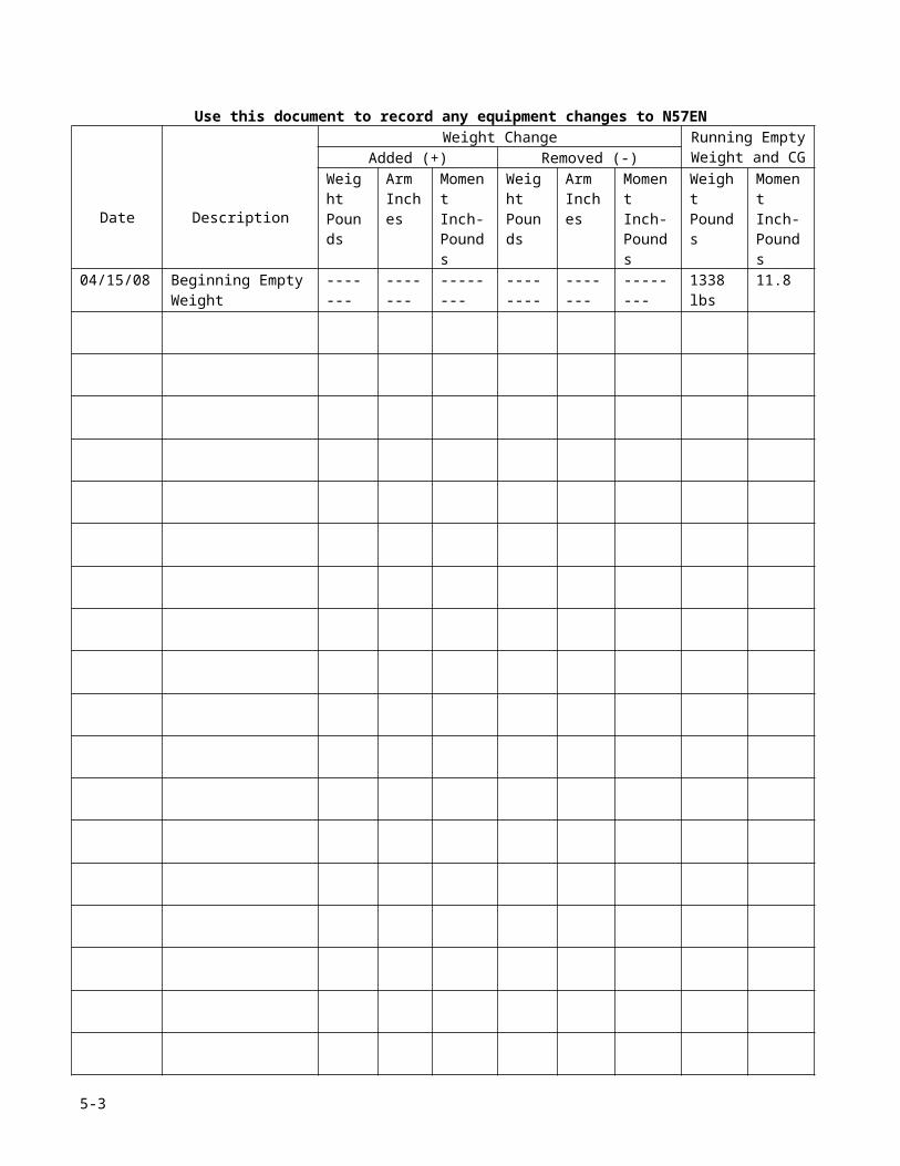
BEARHAWK – N57EN SERIAL #682 SECTION 7 HANDLING, SERVICE & MAINTENANCETo raise the tail wheel, a shop crane and strap can be used to raise the tail by the lower longeron handles. Alternatively, the tail may be manually lifted and the lower longeron handles rested on a sawhorse with blocks on each side under the handles.
Leveling
The fuselage is level when a level or Smartlevel placed on top of either front door sill reads level. Alternatively, the side seam of the boot cowl on either side may be used for leveling.
Flyable Storage
Airplanes placed in non-operational storage for a maximum of 30 days are considered in flyable storage status. Every seventh day during these periods, the propeller should be rotated by hand through five revolutions. This action “limbers” the oil and prevents any accumulation of corrosion on engine cylinder walls.
WARNING
For maximum safety, check that the ignition switches are OFF, the throttle is closed, the mixture control is in the idle cut-off position, and the airplane is secured before rotating the propeller by hand. Do not stand within the arc of the propeller blades while turning the propeller. Always treat the propeller as if the engine will start.
After 30 days, the airplane should be flown for 30 minutes or a ground runup should be made just long enough to produce an oil temperature within the lower green arc range (>165° F). Excessive ground runup should be avoided.
Engine runup also helps to eliminate excessive accumulations of water in the fuel system and other air spaces in the engine. Keep tanks full to minimize condensation in the tanks. Keep the batteries fully charged to prevent the electrolyte from freezing in cold weather.
SERVICING
Engine Oil
Oil Grade (Specification):MIL-L-6082 Aviation Grade Straight Mineral Oil: Use
to replenish supply during first 25 hours and at the first 25-hour oil change. Continue to use until a total of 50 hours has accumulated or oil consumption has stabilized
Aeroshell 100Plus or equivalent: Use after first 50 hours or oil consumption has stabilized. Change oil and filter every 25 hours thereafter. Change engine oil at least every 6 months even though less than the recommended hours have accumulated. Reduce intervals for prolonged operation in dusty areas, cold climates, or when short flights and long idle periods result in sludging conditions.
Oil Capacity:Sump: 8 U.S. QuartsMinimum Safe Quantity in Sump: 2 U.S. Quarts
Fuel
Approved Fuel Grades (and Colors):93 Octane Auto Fuel (no Ethanol)100LL Grade Aviation Fuel (Blue)100 (Formerly 100/130) Grade Aviation Fuel (Green)
Fuel Capacity: Total Capacity: 52 gallonsTotal Capacity Each Tank: 26 gallonsTotal Usable: 25.5 gallons
Note
To ensure maximum fuel capacity when refueling, place the fuel selector valve in either LEFT, RIGHT or OFF position to prevent cross-feeding.
Landing Gear
Main Wheel Tire Pressure30 psi on 6.00-6, 6-ply or 8-ply rated tires23 psi on 8.00-6, 6-ply or 8-ply rated tires
Tail Wheel Tire Pressure60 to 70 psi on 8” 2.80x2.50, 4-ply rated tire
Oxygen
Not installed.
CLEANING AND CARE
Windshield – Windows
The plastic windshield and windows should be cleaned with an aircraft windshield cleaner. Apply the cleaner sparingly with soft cloths, and rub with moderate pressure until all dirt, oil scum and bug stains are removed. Allow the cleaner to dry, then wipe it off with soft flannel cloths.
Note
7-2

BEARHAWK – N57EN SERIAL #682 SECTION 7 HANDLING, SERVICE & MAINTENANCE
Never use gasoline, benzene, alcohol, acetone, carbon tetrachloride, fire extinguisher or anti-ice fluid, lacquer thinner or glass cleaner to clean the plastic. These materials will attach the plastic and may cause it to craze.
Follow by carefully washing with a mild detergent and plenty of water. Rinses thoroughly, then dry with a clean moist chamois. Do not rub the plastic with a dry cloth since this builds up an electrostatic charge, which attracts dust. Waxing with a good commercial wax will finish the cleaning job. A thin, even coat of wax, polished out by hand with clean soft flannel cloths, will fill in minor scratches and help prevent further scratching.
Painted Surfaces
The painted surfaces can be kept bright by washing with water and mild soap, followed by a rinse with water and drying with cloths or a chamois. Harsh or abrasive soaps or detergents, which cause corrosion or scratches, should never be used. Remove stubborn oil and grease with a cloth moistened with Stoddard solvent.
When the airplane is parked outside in cold climates and it is necessary to remove ice before flight, care should be taken to protect the painted surfaces during ice removal with chemical liquids. A 50-50 solution of isopropyl alcohol and water will satisfactorily remove ice accumulations without damaging the paint. A solution with more than 50% alcohol is harmful and should be avoided. While applying the de-icing solution, keep it away from the windshield and cabin windows since the alcohol will attach the plastic and may cause it to craze.
Propeller Care
Preflight inspection of propeller blades for nicks, and wiping them occasionally with an oily cloth to clean off grass and bug stains will assure long, trouble-free service. Small nicks on the propeller, particularly near the tips and on the leading edges, should be dressed out as soon as possible since these nicks produce stress concentrations, and if ignored, may result in cracks. Never use an alkaline cleaner on the blades; remove grease and dirt with carbon tetrachloride or Stoddard solvent.
Engine Care
The engine may be cleaned with Stoddard solvent, or equivalent, then dried thoroughly.
CAUTION
Particular care should be given to electrical equipment before cleaning. Cleaning fluids should not be allowed to enter the starter, alternator, and the like. Protect these components before saturating the engine with solvents. All other openings should also be covered before cleaning the engine assembly. Caustic cleaning solutions should be used cautiously and should always be properly neutralized after their use.
IMPORTANT PART NUMBERS
Engine and Propeller
EngineManufacturer: LycomingModel Number: O-360-EXPSerial Number: L-5505-39Type: Normally-aspirated, direct-drive, air-cooled, horizontally-opposed, carburetor-equipped, four-cylinder engine with 360 cubic inch displacementHorsepower Rating and Engine Speed: 180 rated BHP at 2700 RPMCompression Ratio: 8.2:1Base Timing Angle: 25° BTDC
CarburetorPrecision Airmotive P/N 10-4161-1Model MA-4-5Serial # K32639
StarterPrestolite Starter
Spark PlugsAutolite UREM40EGap 0.016 to 0.018
7-3

BEARHAWK – N57EN SERIAL #682 SECTION 7 HANDLING, SERVICE & MAINTENANCE
Tighten to 15 ft-lb (180 in-lb)
Oil CoolerNiagra P/N 20003A – 9 rowS/N K06-5014
Brakes (Cleveland)Brake assembly – 30-52Wheel Assembly – 40-75BLinings – 66-105
Important Part Numbers cont.
Engine & Propeller
Alternator –internally regulated P/N 14684
50 amp Regulator set point 14.8 volts
Alternator V- BeltDuralast 15345 (AutoZone)1.1 cm x 87.5 cm
Engine Mount Rubber IsolatorsLord P/N J-7402-5Aircraft Spruce P/N 08-03500
Air Filter AssemblyBrackett BA-5110Replacement Element BA-6108
PropellerSensenich Model Number: M76-EMS-0-56Serial Number: 39591Number of Blades: 2Fixed Pitch Aluminum Propeller Diameter: 76” Pitch: 56 degrees
Fuel System
Fuel CapsAdjust for tight seal when rotated 90 degrees. Caution: Make sure vent hole is open and pointed forward!!!! Lubricate threads lightly with Vaseline or fuel lube. Keep lubricated to prevent galling of threads Replace O rings as required 3/8”I.D x 1/16”C.S and/or 1 3/8” I.D. x 3/16” C.S. Viton or Hi Nitrile
Fuel Selector Valve
Andair FS20B4-F
GascolatorVan’s Aircraft GAS-1Order replacement gasket and screenfrom Van’s Aircrafthttp://www.vansaircraft.com/503.678.6545
Electrical
Battery Odyssey PC680 12 volt
ELT BatteriesDuracell “D” cells (6 each)
Landing/Taxi LightsBulbrite XpDichroic Halogen LampEYF 12V 75WN. Spot
Wingtip Position LightsLED by CreativAirhttp://www.creativair.com/Phone: 719-266-2388
Wingtip Strobe tubeNova – Hide-a-flash clear
Tail Strobe/Position lightWhelen A500A
Strobe PowerAvi-Pak 60 watt, 4 outlet
7-4

BEARHAWK – N57EN SERIAL #682 SECTION 7 HANDLING, SERVICE & MAINTENANCE
ELECTRICAL DATA
Main Power Distribution Bus
Fuse Num
Fuse(Amps)
Circuits
1 3 XM Satellite Radio2 5 Fuel Gauges3 3 Inst. Lights/ Manifold pressure4 10 Taxi Light5 5 Wing Nav Lights6 3 Engine info System7 7 Starter/Ignition8 10 Landing Light9 7 Tail Nav Light10 7 Strobe Power pack
Essential Bus
Fuse Num
Fuse(Amps)
Circuits
E1 3 Trim IndicatorE2 5 Trim PowerE3 - Open - SpareE4 - Open - SpareE5 - Open - SpareE6 3 IntercomE7 7 Icom A200 Comm RadioE8 3 Dynon D100 EFISE9 3 Lowrance 2000C GPSE10 3 Collins Transponder
Always On Bus
Fuse Num
Fuse(Amps)
Circuits
A1 10 Dome LightsA2 15 Cig LighterA3 3 EFIS keep aliveA4 - Open - SpareA5 - Open - SpareA6 10 Power to Essential Bus
7-5

BEARHAWK – N57EN SERIAL #682 SECTION 7 HANDLING, SERVICE & MAINTENANCE
Wiring Schematic

BEARHAWK – N57EN SERIAL #682 SECTION 7 HANDLING, SERVICE & MAINTENANCE

BEARHAWK – N57EN SERIAL #682 SECTION 8 Annual Condition Inspection Checklist
BEARHAWK N57ENCONDITION INSPECTION CHECKLIST
Condition Inspection Consumables
o Spark Plugs - Autolite UREM40E (if needed)o ELT batteries – Duracell “D” cell – 6 eacho Oil – Aeroshell 100Plus – 7 qts.o Oil Sample Kit (Aviation Laboratories)o ATF fluid for gear struts (if needed)o Alternator belt - Duralast 15345 (AutoZone) 1.1 cm x 87.5 cm (if needed)o Air filter replacement element (BA-6108)o Battery - Odyssey PC680 12 volt (if needed)o Brake Linings Cleveland 66-105 (8 ea) plus rivetso Brake fluid Aeroshell #41o Main Tires - 6.00 x 6 (6 ply or 8 ply) and tubeso Tailwheel – 8” 2.80x2.50, (4-ply rated tire) and tube
Firewall Forward
o Fly plane, warm up oilo Note EIS tach time ___________o Drain oil o Send out oil analysiso Remove spinnero Inspect spinner for cracks and wearo Inspect spinner bulkheads for crackso Inspect propeller attach hardware and safety wireo Inspect and clean propeller hub exterioro Clean propeller bladeso Inspect propeller blades for nicks and crackso File/smooth out nicks in propeller bladeso Paint propeller (if necessary)o Remove engine cowlingo Remove top plugso Differential compression test:
o #1: /80o #2: /80o #3: /80o #4: /80
o Check mag timing 25 degrees BTDCo Check propeller blade track (while top spark plugs removed)o Clean and inspect top spark plug condition and gap to .016” or replaceo Remove bottom spark plugso Clean and inspect bottom spark plugs, gap to .016” or replaceo Rotate bottom plugs to top, and swap left to right sideso Lubricate sparks plug threads and re-installo Inspect alternator belt for condition and tensiono Inspect starter ring gear teetho Remove batteryo Remove air filtero Inspect airbox for crackso Remove and inspect heat SCAT tubing
8-1
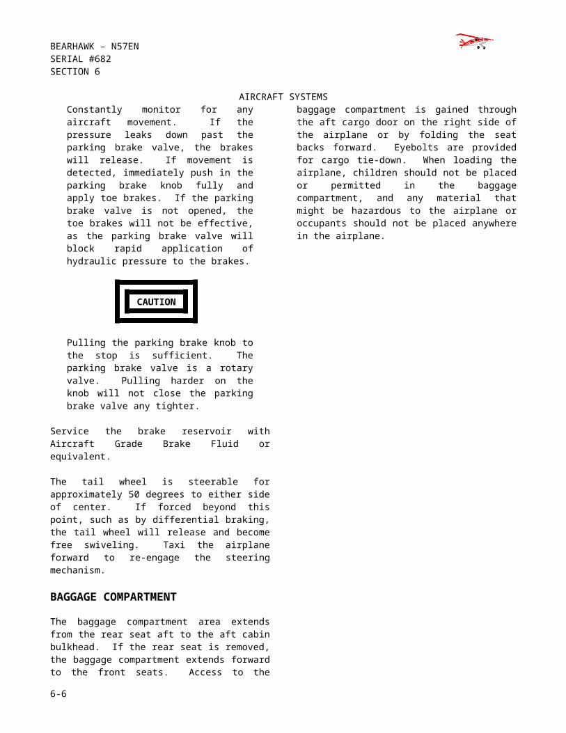
BEARHAWK – N57EN SERIAL #682 SECTION 8 Annual Condition Inspection Checklisto Clean air filter with K&N air filter cleaner, let dryo Clean engineo Inspect exhaust for crackso Inspect engine controls
o Throttleo Mixtureo Carb heat
o Inspect heat muffso Inspect engine mount for crackso Inspect firewallo Inspect oil coolero Inspect baffleso Inspect hoses and fittingso Inspect brake fluid reservoir, check fluid levelo Torque intake boltso Torque exhaust boltso Lubricate engine controls with LPS-2o Lubricate throttle shafto Inspect and clean oil screenso Fill sump with 7 quarts of Aeroshell 100 pluso Service air filter with K&N air filter oilo Reinstall air filter o Have battery testedo Install new battery (if necessary)o Run up engine, check for leakso Inspect top and bottom cowling and hingeso Reinstall cowlingNotes:__________________________________________________________________________________________________________________________________________________________________________________________________________________________________________________________________________________________________________________________________________________________________________________________
Main Landing Gear
o Inspect tireso Inspect main landing gearo Inspect brake lines and caliperso Remove wheels and tireso Install new brake linings (if necessary)o Separate wheel halves, remove all bearing componentso Clean bearing components and inspect for pittingo Repack wheel bearings with Aeroshell #5o Reassemble wheels and tires, rotate tires (if necessary)o Bleed brakes (if necessary)o Inflate tires to 30 psiNotes:______________________________________________________________________________________________________________________________________________________________________________________________________________________________________________________________________________________________________
8-1
BEARHAWK – N57EN SERIAL #682 SECTION 8 Annual Condition Inspection Checklist
Tailwheel
o Inspect tailwheelo Inspect tailwheel fork and springo Inspect tailwheel steering linko Disassemble and clean tailwheel forko Inspect condition of rudder lock keyo Lubricate tailwheel bearings with Aeroshell #5o Rotate tailwheel (if necessary)o Inflate to 60 to 70 psi
Notes:______________________________________________________________________________________________________________________________________________________________________________________________________________________________________________________________________________________________________
Right wingo Check operation of position lighto Check operation of strobe flashero Check operation of taxi lighto Remove wing tipo Remove lower access panelso Remove wing root fairingo Inspect wires & connectionso Inspect exterior wing surfaces for crackso Inspect fuel tank exterior for leakso Inspect aileron exterior for cracks, cuts or tearso Inspect aileron hinge bracketso Inspect aileron counterweight “pipe”o Inspect flap exterior for cracks, cuts or tearso Inspect interior wing structure and interior of skinso Inspect condition of pushrodso Inspect bellcrank, turnbuckles, pulleys and cables for play and wearo Lubricate bellcrank & rod end bearings with LPS-2o Lubricate aileron hinges with LPS-2o Inspect flap hinges and lubricate with LPS-2o Inspect flap return springso Lubricate flap pushrod end bearings with LPS-2o Lubricate flap drive bushings via grease fittingso Inspect fuel cap, lubricate with EZ-Turn o Inspect fuel tank interioro Inspect fuel draino Inspect fuel tank root rib for leakso Inspect fuel lines and fittingso Inspect fuel quantity sender & wiringo Inspect front sparo Inspect wing root areao Inspect rear spar attach pointo Actuate flaps and inspect through range of travelo Reinstall wing tipo Reinstall lower access panelso Reinstall wing root fairing
8-1

BEARHAWK – N57EN SERIAL #682 SECTION 8 Annual Condition Inspection ChecklistNotes:_______________________________________________________________________________________________________________________________________________________________________________________________________________________________________________________________________________________________________
Left wing
o Check operation of position lighto Check operation of strobe flashero Check operation of landing lighto Remove wing tipo Remove lower access panelso Remove wing root fairingo Inspect lighting wires & connectionso Inspect remote compass module and wiringo Inspect OAT and wiringo Inspect pitot tube and connectionso Inspect exterior wing surfaces for crackso Inspect fuel tank exterior for leakso Inspect aileron exterior for cracks, cuts or tearso Inspect aileron hinge bracketso Inspect aileron counterweight “pipe”o Inspect flap exterior for cracks, cuts or tearso Inspect interior wing structure and interior of skinso Inspect condition of pushrodso Inspect bellcrank, turnbuckles, pulleys and cables for play and wearo Lubricate bellcrank & rod end bearings with LPS-2o Lubricate aileron hinges with LPS-2o Inspect flap hinges and lubricate with LPS-2o Inspect flap return springso Lubricate flap pushrod end bearings with LPS-2o Lubricate flap drive bushings via grease fittingso Inspect fuel cap, lubricate with EZ-Turn (if necessary)o Inspect fuel tank interioro Inspect fuel draino Inspect fuel tank root rib for leakso Inspect fuel lines and fittingso Inspect fuel quantity sender & wiringo Inspect front sparo Inspect wing root areao Inspect rear spar attach pointo Actuate flaps and inspect through range of travelo Reinstall wing tipo Reinstall lower access panelso Reinstall Wing root fairingsNotes:_______________________________________________________________________________________________________________________________________________________________________________________________________________________________________________________________________________________________________
8-1

BEARHAWK – N57EN SERIAL #682 SECTION 8 Annual Condition Inspection Checklist
Tailcone and Empennage
o Remove empennage fairings and tail inspection panelso Inspect longerons, VS and HS attachment pointso Inspect HS brace supportso Inspect all tailwires for proper tension and thread engagemento Inspect tail spring mount bolts and weldmentso Lubricate elevator cable ends and trim tab actuatotr with LPS-2o Lubricate elevator hinges via grease fittings o Lubricate rudder hinges via grease fittingso Inspect rudder cable clevis ends and hardwareo Inspect rudder stopso Inspect exterior of tail surfaces for cracks, cuts and tearso Inspect elevator counterweights for securityo Inspect trim tab, hinge, pin securedo Inspect rudder light and elevator trim wiringo Check operation of elevator trimo Check operation of tail position lighto Check operation of tail strobe flashero Reinstall all covers and gap fairings
Notes:_______________________________________________________________________________________________________________________________________________________________________________________________________________________________________________________________________________________________________
Fuselage Exterioro Inspect exterior skins for cracks, cuts and tearso Inspect static portso Clean & inspect bellyo Remove gear leg fairingso Remove bottom skin between landing gear legso Disassemble, clean and inspect gascolatoro Inspect fuel lines for any wear or chaffingo Inspect all wiring under floor panso Inspect brake lines for leaks or chaffingo Inspect landing gear and all attachmentso Inspect external antennaso Inspect condition of rear windowso Inspect door skins for cracks or loose rivetso Inspect and lubricate all door hinges and latcheso Inspect front side windows for cracks or crazingo Inspect windshield for cracks or crazingo Inspect coot cowlNotes:_______________________________________________________________________________________________________________________________________________________________________________________________________________________________________________________________________________________________________
8-1

BEARHAWK – N57EN SERIAL #682 SECTION 8 Annual Condition Inspection Checklist
Fuselage Interior
o Remove front and rear seatso Remove center floor panelso Remove front floor panelso Remove covers in ceilingo Remove rear baggage bulkheado Inspect fuselage aft of baggage compartmento Inspect static port hoses and connectionso Inspect and lubricate rudder and brake pedal assemblyo Inspect brake lines and rudder cable connectionso Inspect control stick assembly and lubricateo Inspect and lubricate elevator bellcrank assemblyo Inspect both gang pulleyso Inspect flap cables, pulleys and turnbuckleso Inspect and lubricate flap handle assemblyo Check landing gear strut fluid levels (fill with ATF as needed)o Inspect ELT mounto Replace ELT batteries (if necessary)o Test ELT with radio tuned to 121.5 (5 minutes past the hour)o Inspect strobe power supplyo Inspect trim and flap relays and wiringo Inspect antenna connectionso Inspect all seat beltso Inspect parking brake and cableo Inspect instruments, avionics, and wiringo Inspect manifold pressure tubingo Inspect firewall and forward fuselage structureo Reinstall all cover panelso Reinstall floor cover panels, seats, and rear baggage bulkheado Reinstall exterior skins and covers
Notes:_______________________________________________________________________________________________________________________________________________________________________________________________________________________________________________________________________________________________________
This condition inspection was completed on ________/________/_________
_________________________________________________________________Printed Name
__________________________________________________________________Signature and Certificate Number
8-1

BEARHAWK – N57EN SERIAL #682 SECTION 8 Annual Condition Inspection Checklist
8-1