
N5 PCIe Flash Array - Promark...
27
www.pivot3.com N5 PCIe Flash Array ARCHITECTURE WHITEPAPER
Transcript of N5 PCIe Flash Array - Promark...

Architecture Whitepaper – N5 PCIe Flash Array
2© 2016 Pivot3, Inc. All rights reserved. Pivot3 reserves the right to make changes without further notice to any products herein. The content provided is as is and without express or implied warranties of any kind.
Table of ContentsData Value . . . . . . . . . . . . . . . . . . . . . . . . . . . . . . . . . . . . . . . . . . . . . . . . . . . . . . . . . . . . . . . . . . . . . . . . . . 3
Pivot3 N5 PCIe Flash Array Architecture . . . . . . . . . . . . . . . . . . . . . . . . . . . . . . . . . . . . . . . . . . . . . . . . . 4
Storage Quality of Service and Service Levels . . . . . . . . . . . . . . . . . . . . . . . . . . . . . . . . . . . . . . . . . . . . . . . . . . 5
PCIe Flash Multi-tier Design . . . . . . . . . . . . . . . . . . . . . . . . . . . . . . . . . . . . . . . . . . . . . . . . . . . . . . . . . . . . . . . . . . . 10
Dynamic Data Path . . . . . . . . . . . . . . . . . . . . . . . . . . . . . . . . . . . . . . . . . . . . . . . . . . . . . . . . . . . . . . . . . . . . . . . . . . . 11
Data Reduction . . . . . . . . . . . . . . . . . . . . . . . . . . . . . . . . . . . . . . . . . . . . . . . . . . . . . . . . . . . . . . . . . . . . . . . . . . . . . . 18
Active-Active High Availability and Performance . . . . . . . . . . . . . . . . . . . . . . . . . . . . . . . . . . . . . . . . . . . . . . . . 21
Management . . . . . . . . . . . . . . . . . . . . . . . . . . . . . . . . . . . . . . . . . . . . . . . . . . . . . . . . . . . . . . . . . . . . . . . . . . . . . . . . 23
Scalability . . . . . . . . . . . . . . . . . . . . . . . . . . . . . . . . . . . . . . . . . . . . . . . . . . . . . . . . . . . . . . . . . . . . . . . . . . . . . . . . . . . 25
Conclusion . . . . . . . . . . . . . . . . . . . . . . . . . . . . . . . . . . . . . . . . . . . . . . . . . . . . . . . . . . . . . . . . . . . . . . . . . . 27

Architecture Whitepaper – N5 PCIe Flash Array
3© 2016 Pivot3, Inc. All rights reserved. Pivot3 reserves the right to make changes without further notice to any products herein. The content provided is as is and without express or implied warranties of any kind.
Data ValueIn a recent customer survey1, 94% of respondents stated that the ability to manage data based on its business value importance would be valuable to their organization. However, only 32% of respondents were actively practicing this type of data management.
GAP94%
94% of IT Pros considerit valuable to manage data based on the business value of it
Only 32% of them are doing it – because it’s really hard .
32%
Figure 1: Data Value Management - %-respondents that see value vs. those actively doing it.
Why the gap between what customers want (managing data according to business value) vs. doing nothing? Until now, this functionality has been financially out of reach for most customers. Storage systems were never designed to help customers prioritize data based on their unique priorities and the value of their data. Solving these challenges was one of the founding principles around Pivot3’s PCIe Flash Array architecture that is described in this paper.
1. IDG; December, 2014; “Market Pulse Research: Data Storage Management Strategies, Expectations, and Challenges”
Architecture Whitepaper – N5 PCIe Flash Array
4© 2016 Pivot3, Inc. All rights reserved. Pivot3 reserves the right to make changes without further notice to any products herein. The content provided is as is and without express or implied warranties of any kind.
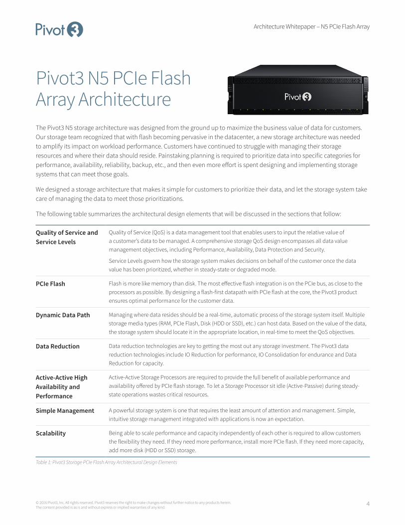
Pivot3 N5 PCIe Flash Array ArchitectureThe Pivot3 N5 storage architecture was designed from the ground up to maximize the business value of data for customers. Our storage team recognized that with flash becoming pervasive in the datacenter, a new storage architecture was needed to amplify its impact on workload performance. Customers have continued to struggle with managing their storage resources and where their data should reside. Painstaking planning is required to prioritize data into specific categories for performance, availability, reliability, backup, etc., and then even more effort is spent designing and implementing storage systems that can meet those goals.
We designed a storage architecture that makes it simple for customers to prioritize their data, and let the storage system take care of managing the data to meet those prioritizations.
The following table summarizes the architectural design elements that will be discussed in the sections that follow:
Quality of Service and Service Levels
Quality of Service (QoS) is a data management tool that enables users to input the relative value of a customer’s data to be managed. A comprehensive storage QoS design encompasses all data value management objectives, including Performance, Availability, Data Protection and Security.
Service Levels govern how the storage system makes decisions on behalf of the customer once the data value has been prioritized, whether in steady-state or degraded mode.
PCIe Flash Flash is more like memory than disk. The most effective flash integration is on the PCIe bus, as close to the processors as possible. By designing a flash-first datapath with PCIe flash at the core, the Pivot3 product ensures optimal performance for the customer data.
Dynamic Data Path Managing where data resides should be a real-time, automatic process of the storage system itself. Multiple storage media types (RAM, PCIe Flash, Disk (HDD or SSD), etc.) can host data. Based on the value of the data, the storage system should locate it in the appropriate location, in real-time to meet the QoS objectives.
Data Reduction Data reduction technologies are key to getting the most out any storage investment. The Pivot3 data reduction technologies include IO Reduction for performance, IO Consolidation for endurance and Data Reduction for capacity.
Active-Active High Availability and Performance
Active-Active Storage Processors are required to provide the full benefit of available performance and availability offered by PCIe flash storage. To let a Storage Processor sit idle (Active-Passive) during steady- state operations wastes critical resources.
Simple Management A powerful storage system is one that requires the least amount of attention and management. Simple, intuitive storage management integrated with applications is now an expectation.
Scalability Being able to scale performance and capacity independently of each other is required to allow customers the flexibility they need. If they need more performance, install more PCIe flash. If they need more capacity, add more disk (HDD or SSD) storage.
Table 1: Pivot3 Storage PCIe Flash Array Architectural Design Elements
Architecture Whitepaper – N5 PCIe Flash Array
5© 2016 Pivot3, Inc. All rights reserved. Pivot3 reserves the right to make changes without further notice to any products herein. The content provided is as is and without express or implied warranties of any kind.
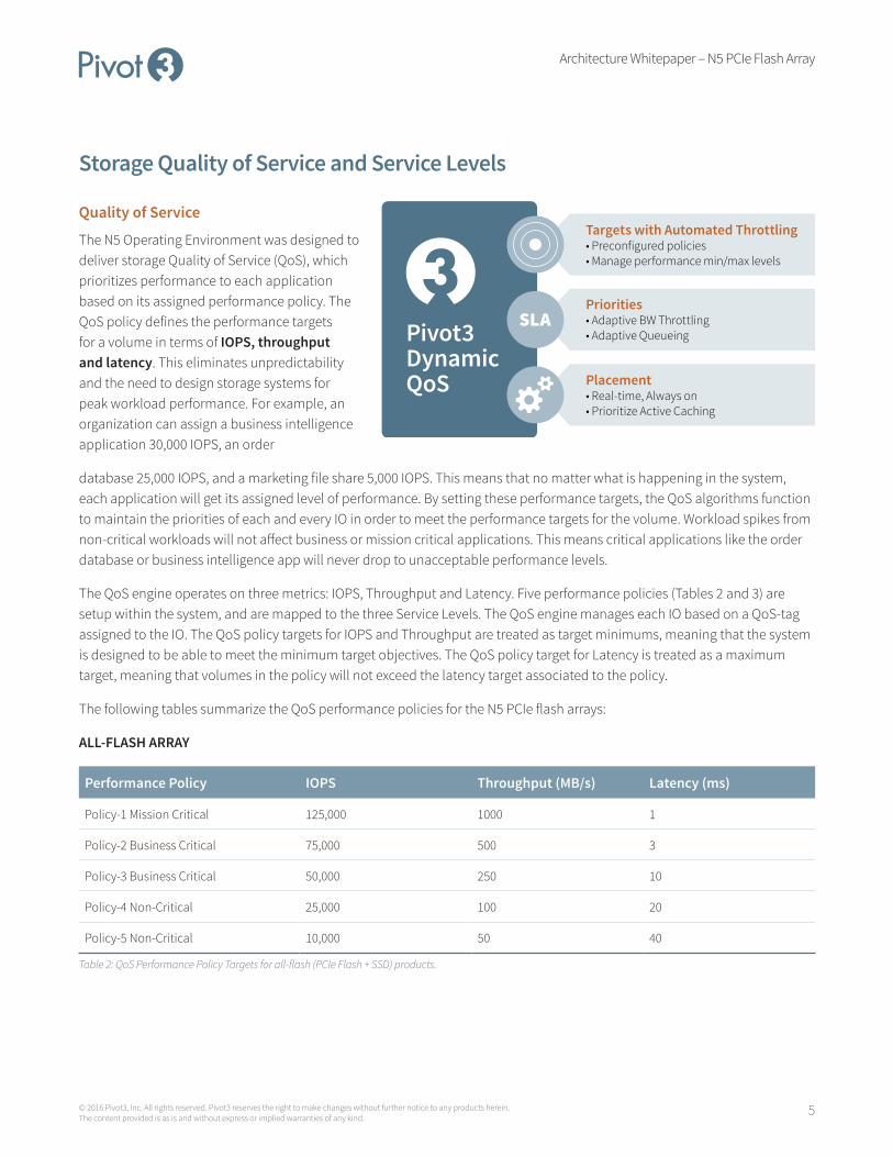
Storage Quality of Service and Service Levels
Quality of Service
The N5 Operating Environment was designed to deliver storage Quality of Service (QoS), which prioritizes performance to each application based on its assigned performance policy. The QoS policy defines the performance targets for a volume in terms of IOPS, throughput and latency. This eliminates unpredictability and the need to design storage systems for peak workload performance. For example, an organization can assign a business intelligence application 30,000 IOPS, an order
database 25,000 IOPS, and a marketing file share 5,000 IOPS. This means that no matter what is happening in the system, each application will get its assigned level of performance. By setting these performance targets, the QoS algorithms function to maintain the priorities of each and every IO in order to meet the performance targets for the volume. Workload spikes from non-critical workloads will not affect business or mission critical applications. This means critical applications like the order database or business intelligence app will never drop to unacceptable performance levels.
The QoS engine operates on three metrics: IOPS, Throughput and Latency. Five performance policies (Tables 2 and 3) are setup within the system, and are mapped to the three Service Levels. The QoS engine manages each IO based on a QoS-tag assigned to the IO. The QoS policy targets for IOPS and Throughput are treated as target minimums, meaning that the system is designed to be able to meet the minimum target objectives. The QoS policy target for Latency is treated as a maximum target, meaning that volumes in the policy will not exceed the latency target associated to the policy.
The following tables summarize the QoS performance policies for the N5 PCIe flash arrays:
ALL-FLASH ARRAY
Performance Policy IOPS Throughput (MB/s) Latency (ms)
Policy-1 Mission Critical 125,000 1000 1
Policy-2 Business Critical 75,000 500 3
Policy-3 Business Critical 50,000 250 10
Policy-4 Non-Critical 25,000 100 20
Policy-5 Non-Critical 10,000 50 40
Table 2: QoS Performance Policy Targets for all-flash (PCIe Flash + SSD) products.
Pivot3DynamicQoS
Targets with Automated Throttling• Preconfigured policies• Manage performance min/max levels
Priorities• Adaptive BW Throttling• Adaptive Queueing
Placement• Real-time, Always on• Prioritize Active Caching

Architecture Whitepaper – N5 PCIe Flash Array
6© 2016 Pivot3, Inc. All rights reserved. Pivot3 reserves the right to make changes without further notice to any products herein. The content provided is as is and without express or implied warranties of any kind.
HYBRID ARRAY
Performance Policy IOPS Throughput (MB/s) Latency (ms)
Policy-1 Mission Critical 100,000 750 5
Policy-2 Business Critical 50,000 375 10
Policy-3 Business Critical 20,000 150 25
Policy-4 Non-Critical 10,000 75 50
Policy-5 Non-Critical 2,000 37.5 100
Table 3: QoS Performance Policy Targets for hybrid (PCIe Flash + HDD) products.
Setting the QoS performance policy of a volume is done at time of its creation, and can be changed anytime in real-time to dynamically adjust the relative priority and performance of the volume. For instance, if a customer wants to allocate more performance to a SQL Reports volume for month-end reporting, they can simply go into one the management interfaces (UI, CLI or vCenter Plugin) and adjust the QoS policy on the volume.
The following screenshot highlights the QoS Performance Policy targets for “Policy-1 Mission Critical”:
Figure 2: QoS Performance Policy screenshot.

Architecture Whitepaper – N5 PCIe Flash Array
7© 2016 Pivot3, Inc. All rights reserved. Pivot3 reserves the right to make changes without further notice to any products herein. The content provided is as is and without express or implied warranties of any kind.
The following screenshot shows how easy it is to change a QoS Policy on a volume on-the-fly:
Figure 3: Volume QoS Performance Policy modification screenshot.
Performance monitoring capabilities in the user interface allow performance to be monitored real-time, and viewed up to one year prior. Volume QoS policies can be adjusted to ensure that configurations are always optimized. Storage QoS prioritizes storage performance levels, so you can be confident that your system is as powerful, cost-effective and efficient as possible.
Architecture Whitepaper – N5 PCIe Flash Array
8© 2016 Pivot3, Inc. All rights reserved. Pivot3 reserves the right to make changes without further notice to any products herein. The content provided is as is and without express or implied warranties of any kind.
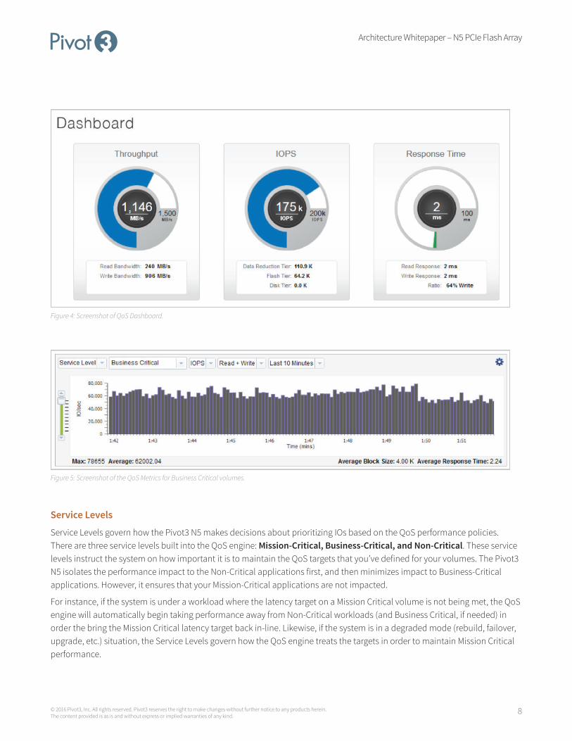
Figure 4: Screenshot of QoS Dashboard.
Figure 5: Screenshot of the QoS Metrics for Business Critical volumes.
Service Levels
Service Levels govern how the Pivot3 N5 makes decisions about prioritizing IOs based on the QoS performance policies. There are three service levels built into the QoS engine: Mission-Critical, Business-Critical, and Non-Critical. These service levels instruct the system on how important it is to maintain the QoS targets that you’ve defined for your volumes. The Pivot3 N5 isolates the performance impact to the Non-Critical applications first, and then minimizes impact to Business-Critical applications. However, it ensures that your Mission-Critical applications are not impacted.
For instance, if the system is under a workload where the latency target on a Mission Critical volume is not being met, the QoS engine will automatically begin taking performance away from Non-Critical workloads (and Business Critical, if needed) in order the bring the Mission Critical latency target back in-line. Likewise, if the system is in a degraded mode (rebuild, failover, upgrade, etc.) situation, the Service Levels govern how the QoS engine treats the targets in order to maintain Mission Critical performance.

Architecture Whitepaper – N5 PCIe Flash Array
9© 2016 Pivot3, Inc. All rights reserved. Pivot3 reserves the right to make changes without further notice to any products herein. The content provided is as is and without express or implied warranties of any kind.
You are able to proactively define the amount of resources a volume will receive during an event. Figure 6 shows the Metrics screen for the three service levels. During a VDI boot storm, Mission Critical performance is maintained while Business Critical performance is impacted to the accepted target levels.
Figure 6: Metrics screenshot during VDI boot storm.
With any other storage system, there is no way to prioritize performance in this manner based on the business value of the data. Not the case with the Pivot3 N5. Since the volumes associated with the Exchange workload were categorized as Mission-Critical, SQL reports as Business-Critical, and VDI as Non-Critical, the Pivot3 N5 knows exactly where to allocate resources during an event.
Architecture Whitepaper – N5 PCIe Flash Array
10© 2016 Pivot3, Inc. All rights reserved. Pivot3 reserves the right to make changes without further notice to any products herein. The content provided is as is and without express or implied warranties of any kind.
PCIe Flash Multi-tier Design
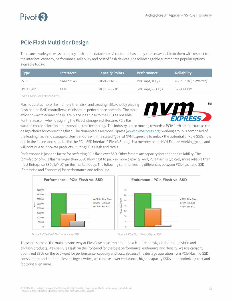
There are a variety of ways to deploy flash in the datacenter. A customer has many choices available to them with respect to the interface, capacity, performance, reliability and cost of flash devices. The following table summarizes popular options available today:
Type Interfaces Capacity Points Performance Reliability
SSD SATA or SAS 80GB – 1.6TB 190K iops, 1GB/s 4 – 35 PBW (PB Written)
PCIe Flash PCIe 200GB – 5.2TB 380K iops, 2.7 GB/s 12 – 64 PBW
Table 4: Flash/Solid-state Choices.
Flash operates more like memory than disk, and treating it like disk by placing flash behind RAID controllers diminishes its performance potential. The most efficient way to connect flash is to place it as close to the CPU as possible. For that reason, when designing the Pivot3 storage architecture, PCIe flash was the choice selection for flash/solid-state technology. The industry is also moving towards a PCIe flash architecture as the design choice for connecting flash. The Non-volatile Memory Express (www.nvmexpress.org) working group is composed of the leading flash and storage system vendors with the stated “goal of NVM Express is to unlock the potential of PCIe SSDs now and in the future, and standardize the PCIe SSD interface.” Pivot3 Storage is a member of the NVM Express working group and will continue to innovate products utilizing PCIe Flash and NVMe.
Performance is just one factor for preferring PCIe flash over SSD. Other factors are capacity footprint and reliability. The form-factor of PCIe flash is larger than SSD, allowing it to pack in more capacity. And, PCIe flash is typically more reliable than most Enterprise SSDs (eMLC) on the market today. The following summarizes the differences between PCIe flash and SSD (Enterprise and Economic) for performance and reliability:
Figure 7: PCIe Flash Performance vs. SSD Figure 8: PCIe Flash Reliability vs. SSD
These are some of the main reasons why at Pivot3 we have implemented a Multi-tier design for both our hybrid and all-flash products. We use PCIe Flash on the front-end for the best performance, endurance and density. We use capacity optimized SSDs on the back-end for performance, capacity and cost. Because the destage operation from PCIe Flash to SSD consolidates and de-amplifies the ingest writes, we can use lower endurance, higher capacity SSDs, thus optimizing cost and footprint even more.
Architecture Whitepaper – N5 PCIe Flash Array
11© 2016 Pivot3, Inc. All rights reserved. Pivot3 reserves the right to make changes without further notice to any products herein. The content provided is as is and without express or implied warranties of any kind.
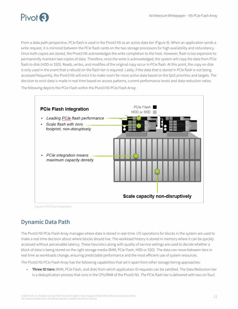
From a data path perspective, PCIe flash is used in the Pivot3 N5 as an active data tier (Figure 9). When an application sends a write request, it is mirrored between the PCIe flash cards on the two storage processors for high availability and redundancy. Once both copies are stored, the Pivot3 N5 acknowledges the write completion to the host. However, flash is too expensive to permanently maintain two copies of data. Therefore, once the write is acknowledged, the system will copy the data from PCIe flash to disk (HDD or SSD). Reads, writes, and modifies of the original copy occur in PCIe flash. At this point, the copy on disk is only used in the event that a rebuild on the flash tier is required. Lastly, if the data that is stored in PCIe flash is not being accessed frequently, the Pivot3 N5 will evict it to make room for more active data based on the QoS priorities and targets. The decision to evict data is made in real time based on access patterns, current performance levels and data-reduction ratios.
The following depicts the PCIe Flash within the Pivot3 N5 PCIe Flash Array:
Figure 9: PCIe Flash Integration.
Dynamic Data Path
The Pivot3 N5 PCIe Flash Array manages where data is stored in real-time. I/O operations for blocks in the system are used to make a real time decision about where blocks should live. The workload history is stored in memory where it can be quickly accessed without perceivable latency. These heuristics along with quality of service settings are used to decide whether a block of data is being stored on the right storage media (RAM, PCIe Flash, HDD or SSD). The data can move between tiers in real time as workloads change, ensuring predictable performance and the most efficient use of system resources.
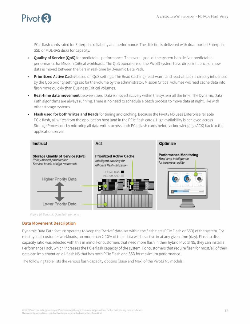
The Pivot3 N5 PCIe Flash Array has the following capabilities that set it apart from other storage tiering approaches:
• Three IO tiers (RAM, PCIe Flash, and disk) from which application IO requests can be satisfied. The Data Reduction tier is a deduplication process that runs in the CPU/RAM of the Pivot3 N5. The PCIe flash tier is delivered with two (or four)
Architecture Whitepaper – N5 PCIe Flash Array
12© 2016 Pivot3, Inc. All rights reserved. Pivot3 reserves the right to make changes without further notice to any products herein. The content provided is as is and without express or implied warranties of any kind.
PCIe flash cards rated for Enterprise reliability and performance. The disk tier is delivered with dual-ported Enterprise SSD or MDL-SAS disks for capacity.
• Quality of Service (QoS) for predictable performance. The overall goal of the system is to deliver predictable performance for Mission Critical workloads. The QoS operations of the Pivot3 system have direct influence on how data is moved between the tiers in real-time by Dynamic Data Path.
• Prioritized Active Cache based on QoS settings. The Read Caching (read-warm and read-ahead) is directly influenced by the QoS priority settings set for the volume by the administrator. Mission Critical volumes will read cache data into flash more quickly than Business Critical volumes.
• Real-time data movement between tiers. Data is moved actively within the system all the time. The Dynamic Data Path algorithms are always running. There is no need to schedule a batch process to move data at night, like with other storage systems.
• Flash used for both Writes and Reads for tiering and caching. Because the Pivot3 N5 uses Enterprise reliable PCIe flash, all writes from the application host land in the PCIe flash cards. High availability is achieved across Storage Processors by mirroring all data writes across both PCIe flash cards before acknowledging (ACK) back to the application server.
Figure 10: Dynamic Data Path elements.
Data Movement Description
Dynamic Data Path feature operates to keep the “Active” data-set within the flash tiers (PCIe Flash or SSD) of the system. For most typical customer workloads, no more than 2-10% of their data will be active in at any given time (day). Flash to disk capacity ratio was selected with this in mind. For customers that need more flash in their hybrid Pivot3 N5, they can install a Performance Pack, which increases the PCIe flash capacity of the system. For customers that require flash for most/all of their data can implement an all-flash N5 that has both PCIe Flash and SSD for maximum performance.
The following table lists the various flash capacity options (Base and Max) of the Pivot3 N5 models.

Architecture Whitepaper – N5 PCIe Flash Array
13© 2016 Pivot3, Inc. All rights reserved. Pivot3 reserves the right to make changes without further notice to any products herein. The content provided is as is and without express or implied warranties of any kind.
Model TypePCIe Flash Capacity
Read/Write Mirror
Prioritized Active Cache* Disk Capacity
N5-200 Hybrid Base: 2TB
Max: 7.2TB
Base: 700GB * 2
Max: 700GB * 2
Base: 600GB
Max: 5800GB
Base: 32TB HDD
Max: 128TB HDD
N5-300 Hybrid Base: 2.6TB
Max: 7.8TB
Base: 800GB * 2
Max: 800GB * 2
Base: 1000GB
Max: 6200GB
Base: 64TB HDD
Max: 256TB HDD
N5-500 Hybrid Base: 5.2TB
Max: 10.4TB
Base: 1600GB * 2
Max: 1600GB * 2
Base: 2000GB
Max: 7200GB
Base: 64TB HDD
Max: 256TB HDD
N5-1000 Hybrid Base: 10.4TB
Max: 15.6TB
Base: 2000GB * 2
Max: 2000GB * 2
Base: 6400GB
Max: 11600GB
Base: 64TB HDD
Max: 256TB HDD
N5-1500 All-flash Base: 2.6TB
Max: 2.6TB
Base: 1300GB * 2
Max: 1300GB * 2
Base: 96GB*
Max: 96GB*
Base: 15TB SSD
Max: 60TB SSD
N5-3000 All-flash Base: 2.6TB
Max: 2.6TB
Base: 1300GB * 2
Max: 1300GB * 2
Base: 96GB*
Max: 96GB*
Base: 30TB SSD
Max: 60TB SSD
Table 5: Flash Capacity Options by Pivot3 N5 model.
*Prioritized Active Cache utilizes RAM and PCIe Flash to provide read-warm and read-ahead functions. The all-flash products use only RAM for PAC operations as a SSD read is already sufficiently accelerated.
The Dynamic Data Path algorithms work in conjunction with the Quality of Service (QoS) engine to keep the active data in flash based on meeting the QoS metrics and priorities set on a per volume (LUN) basis. All things being equal, there will be more Mission Critical data held in flash than Business Critical than Non-Critical.
IO Prioritization
All data IO arrives from the application servers into the Pivot3 N5 array via SCSI commands (encapsulated in a network storage protocol – iSCSI). From the Pivot3 IO stack perspective, the data IO is first prioritized into the system based on the QoS Performance Policy that the volume (LUN) is part of. It is next handed to the rest of the IO stack for processing. Mission Critical IOs are prioritized higher than Business Critical than Non-Critical. Once an IO is released for processing by the QoS engine, it flows through the rest of the Pivot3 IO stack. The Dynamic Data Path Engine is a set of software in the Pivot3 IO stack that manages real-time movement of data between the flash and disk tiers.
Architecture Whitepaper – N5 PCIe Flash Array
14© 2016 Pivot3, Inc. All rights reserved. Pivot3 reserves the right to make changes without further notice to any products herein. The content provided is as is and without express or implied warranties of any kind.
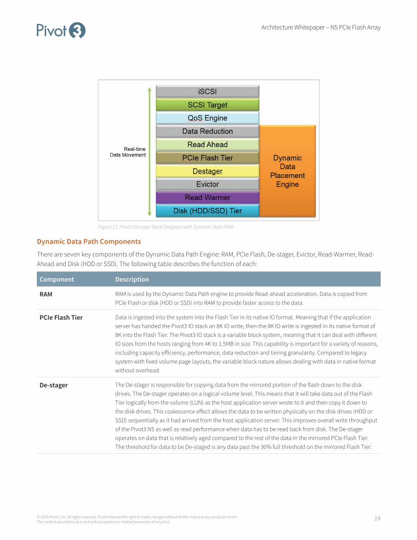
Figure 11: Pivot3 Storage Stack Diagram with Dynamic Data Path
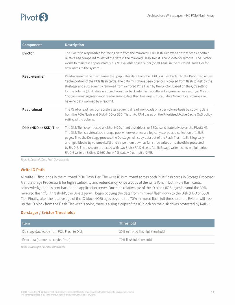
Dynamic Data Path Components
There are seven key components of the Dynamic Data Path Engine: RAM, PCIe Flash, De-stager, Evictor, Read-Warmer, Read-Ahead and Disk (HDD or SSD). The following table describes the function of each:
Component Description
RAM RAM is used by the Dynamic Data Path engine to provide Read-ahead acceleration. Data is copied from PCIe Flash or disk (HDD or SSD) into RAM to provide faster access to the data.
PCIe Flash Tier Data is ingested into the system into the Flash Tier in its native IO format. Meaning that if the application server has handed the Pivot3 IO stack an 8K IO write, then the 8K IO write is ingested in its native format of 8K into the Flash Tier. The Pivot3 IO stack is a variable block system, meaning that it can deal with different IO sizes from the hosts ranging from 4K to 1.5MB in size. This capability is important for a variety of reasons, including capacity efficiency, performance, data reduction and tiering granularity. Compared to legacy system with fixed volume page layouts, the variable block nature allows dealing with data in native format without overhead.
De-stager The De-stager is responsible for copying data from the mirrored portion of the flash down to the disk drives. The De-stager operates on a logical volume level. This means that it will take data out of the Flash Tier logically from the volume (LUN) as the host application server wrote to it and then copy it down to the disk drives. This coalescence effect allows the data to be written physically on the disk drives (HDD or SSD) sequentially as it had arrived from the host application server. This improves overall write throughput of the Pivot3 N5 as well as read performance when data has to be read back from disk. The De-stager operates on data that is relatively aged compared to the rest of the data in the mirrored PCIe Flash Tier. The threshold for data to be De-staged is any data past the 30% full threshold on the mirrored Flash Tier.
Architecture Whitepaper – N5 PCIe Flash Array
15© 2016 Pivot3, Inc. All rights reserved. Pivot3 reserves the right to make changes without further notice to any products herein. The content provided is as is and without express or implied warranties of any kind.
Component Description
Evictor The Evictor is responsible for freeing data from the mirrored PCIe Flash Tier. When data reaches a certain relative age compared to rest of the data in the mirrored Flash Tier, it is candidate for removal. The Evictor works to maintain approximately a 30% available space buffer (or 70% full) in the mirrored Flash Tier for new writes to the system.
Read-warmer Read-warmer is the mechanism that populates data from the HDD Disk Tier back into the Prioritized Active Cache portion of the PCIe flash cards. The data must have been previously copied from flash to disk by the Destager and subsequently removed from mirrored PCIe Flash by the Evictor. Based on the QoS setting for the volume (LUN), data is copied from disk back into flash at different aggressiveness settings. Mission Critical is most aggressive on read-warming data than Business-Critical, while Non-critical volumes will have no data warmed by a read hit.
Read-ahead The Read-ahead function accelerates sequential read workloads on a per volume basis by copying data from the PCIe Flash and Disk (HDD or SSD) Tiers into RAM based on the Prioritized Active Cache QoS policy setting of the volume.
Disk (HDD or SSD) Tier The Disk Tier is composed of either HDDs (hard disk drives) or SSDs (solid state drives) on the Pivot3 N5. The Disk Tier is a virtualized storage pool where volumes are logically stored as a collection of 1.5MB pages. Thru the De-stage process, the De-stager will copy data out of the Flash Tier in 1.5MB logically arranged blocks by volume (LUN) and stripe them down as full stripe writes onto the disks protected by RAID-6. The disks are protected with two 8-disk RAID-6 sets. A 1.5MB page write results in a full-stripe RAID-6 write on 8 disks (256K chunk * (6 data + 2 parity)) of 2MB.
Table 6: Dynamic Data Path Components.
Write IO Path
All write IO first lands in the mirrored PCIe Flash Tier. The write IO is mirrored across both PCIe flash cards in Storage Processor A and Storage Processor B for high availability and redundancy. Once a copy of the write IO is in both PCIe flash cards, acknowledgement is sent back to the application server. Once the relative age of the IO block (IOB) ages beyond the 30% mirrored flash “full threshold”, the De-stager will begin copying the data from mirrored flash down to the Disk (HDD or SSD) Tier. Finally, after the relative age of the IO block (IOB) ages beyond the 70% mirrored flash full threshold, the Evictor will free up the IO block from the Flash Tier. At this point, there is a single copy of the IO block on the disk drives protected by RAID-6.
De-stager / Evictor Thresholds
Item Threshold
De-stage data (copy from PCIe Flash to Disk) 30% mirrored flash full threshold
Evict data (remove all copies from) 70% flash full threshold
Table 7: Destager / Evictor Thresholds.
Architecture Whitepaper – N5 PCIe Flash Array
16© 2016 Pivot3, Inc. All rights reserved. Pivot3 reserves the right to make changes without further notice to any products herein. The content provided is as is and without express or implied warranties of any kind.
Read IO Path
As Read IO is presented to the Pivot3 IO stack on a Storage Processor, the data will either in PCIe flash (flash-hit) or it will be disk (HDD or SSD). Additionally, there will be some data that will be both in PCIe flash and disk, but the Pivot3 IO stack will always prefer to source the Read from PCIe flash. As a general guideline, for a proper performing hybrid (PCIe Flash + HDD)system, we expect no more than 30% of the Read IOs to result in a PCIe flash-miss (where the IO must be satisfied from HDD). If more than 30% of Read IO is coming from disk, the customer should evaluate their workloads and whether or not they need more PCIe flash in the N5 (add a Performance Pack). The all-flash (PCIe Flash + SSD) products will source reads from either PCIe Flash or SSD Flash, thus there is no possibility of a “flash-miss” as all media is flash. Read IO on the all-flash array is 100% flash hit rate.
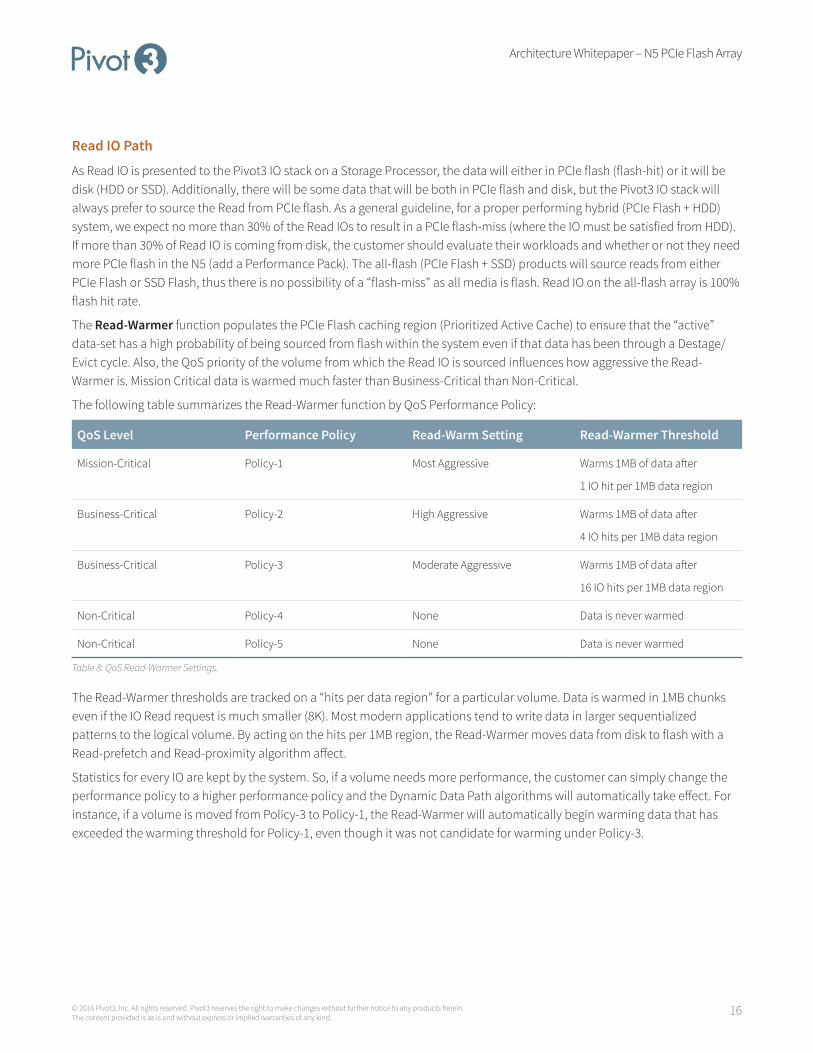
The Read-Warmer function populates the PCIe Flash caching region (Prioritized Active Cache) to ensure that the “active” data-set has a high probability of being sourced from flash within the system even if that data has been through a Destage/Evict cycle. Also, the QoS priority of the volume from which the Read IO is sourced influences how aggressive the Read-Warmer is. Mission Critical data is warmed much faster than Business-Critical than Non-Critical.
The following table summarizes the Read-Warmer function by QoS Performance Policy:
QoS Level Performance Policy Read-Warm Setting Read-Warmer Threshold
Mission-Critical Policy-1 Most Aggressive Warms 1MB of data after
1 IO hit per 1MB data region
Business-Critical Policy-2 High Aggressive Warms 1MB of data after
4 IO hits per 1MB data region
Business-Critical Policy-3 Moderate Aggressive Warms 1MB of data after
16 IO hits per 1MB data region
Non-Critical Policy-4 None Data is never warmed
Non-Critical Policy-5 None Data is never warmed
Table 8: QoS Read-Warmer Settings.
The Read-Warmer thresholds are tracked on a “hits per data region” for a particular volume. Data is warmed in 1MB chunks even if the IO Read request is much smaller (8K). Most modern applications tend to write data in larger sequentialized patterns to the logical volume. By acting on the hits per 1MB region, the Read-Warmer moves data from disk to flash with a Read-prefetch and Read-proximity algorithm affect.
Statistics for every IO are kept by the system. So, if a volume needs more performance, the customer can simply change the performance policy to a higher performance policy and the Dynamic Data Path algorithms will automatically take effect. For instance, if a volume is moved from Policy-3 to Policy-1, the Read-Warmer will automatically begin warming data that has exceeded the warming threshold for Policy-1, even though it was not candidate for warming under Policy-3.

Architecture Whitepaper – N5 PCIe Flash Array
17© 2016 Pivot3, Inc. All rights reserved. Pivot3 reserves the right to make changes without further notice to any products herein. The content provided is as is and without express or implied warranties of any kind.
Figure 12: Prioritized Active Cache data movement.
The Read-Ahead function of the product accelerates sequential read workloads on a volume basis. Leveraging a portion of RAM from each Storage Processor, the Pivot3 IO stack will pre-fetch copy data from PCIe Flash and/or disk (HDD or SSD) into RAM to accelerate application IOs. There are potential 128 individual read-ahead streams (64 per Storage Processor) that can be active at any given time. Up to 4 sub-streams can be active on a volume at a time.
The following table summarizes the Read-Ahead function by QoS Performance Policy:
QoS Level Performance Policy Read-Ahead Setting
Mission-Critical Policy-1 On
Business-Critical Policy-2 On
Business-Critical Policy-3 On
Non-Critical Policy-4 None
Non-Critical Policy-5 None
Table 9: QoS Read-Ahead Settings.

Architecture Whitepaper – N5 PCIe Flash Array
18© 2016 Pivot3, Inc. All rights reserved. Pivot3 reserves the right to make changes without further notice to any products herein. The content provided is as is and without express or implied warranties of any kind.
Data Reduction
The Pivot3 N5 PCIe Flash Array family of products employ three different data reduction technologies to improve performance, extend Flash life and reduce capacity. The following table summarizes these capabilities.
Technology Description
IO Reduction Inline IO reduction for 2 .5X performance improvement. 1
The Pivot3 pattern match function reduces the IO footprint of the data by stripping common patterns out of the write ingest data stream. If a piece of data is identified as a recognized pattern, metadata is updated, and no data IO is performed. This results in less actual writes to PCIe Flash, SSD and/or HDD.
IO Consolidation IO Consolidation for 4X endurance and performance. 2
Data is ingested directly into the PCIe Flash tier of the N5. This allows for rapid ingest of data from a variety of hosts with very different data streams. The resultant workload is typically a highly randomized variable block write. The Pivot3 IO Consolidation technology takes these writes out of PCIe Flash, serializes and consolidates them before pushing them to either the SSD or HDD tier. The resultant behavior is write de-amplification on the SSDs and higher performance on the HDDs.
Capacity Reduction Inline data reduction for 50% capacity reduction. 3
The Pivot3 pattern match function compresses the capacity of the data by stripping common patterns out of the write ingest data stream. If a piece of data is identified as a recognized pattern, metadata is update, and no data is stored. If the application server requests the data, the pattern is generated out of CPU/RAM of the storage processor on the N5.
Table 10: Data Reduction Technologies.
IO Reduction for Performance
The Pivot3 IO Reduction technology is an inline pattern match deduplication function that recognizes common patterns in the data stream and immediately strips them at an individual block level. The only data that has to be stored is the metadata describing the actual data. Because the IO never makes it to storage media, there is an immediate performance benefit for the application. The IO Reduction performed is counted as part of the Data Reduction Tier iops in the Pivot3 user interface right on the dashboard. Customers can see up to 2 .5X the iops and more than 50% reduction in latency for workloads serviced from the IO Reduction engine versus the PCIe Flash tier.
The IO Reduction metrics are available via the Pivot3 metrics feature. Up to a year’s worth of metrics data is available for viewing and downloading by the customer.
Architecture Whitepaper – N5 PCIe Flash Array
19© 2016 Pivot3, Inc. All rights reserved. Pivot3 reserves the right to make changes without further notice to any products herein. The content provided is as is and without express or implied warranties of any kind.
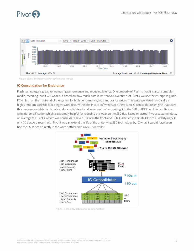
Figures 13 and 14: Data Reduction performance metrics.
IO Consolidation for Endurance
Flash technology is great for increasing performance and reducing latency. One property of Flash is that it is a consumable media, meaning that it will wear-out based on how much data is written to it over time. At Pivot3, we use the enterprise grade PCIe Flash on the front-end of the system for high performance, high endurance writes. This write workload is typically a highly random, variable block ingest workload. Within the Pivot3 software stack there is an IO consolidation engine that takes this random, variable block data and consolidates it and serializes it when writing it to the SSD or HDD tier. This results in a write de-amplification which is extremely helpful for reducing the wear on the SSD tier. Based on actual Pivot3 customer data, on average the Pivot3 system will consolidate seven IOs from the front-end PCIe Flash tier to a single IO to the underlying SSD or HDD tier. As a result, with Pivot3 we can extend the life of the underlying SSD technology by 4X what it would have been had the SSDs been directly in the write path behind a RAID controller.
Figure 15: IO Consolidation write de-amplification.
Architecture Whitepaper – N5 PCIe Flash Array
20© 2016 Pivot3, Inc. All rights reserved. Pivot3 reserves the right to make changes without further notice to any products herein. The content provided is as is and without express or implied warranties of any kind.
Data Reduction for Capacity
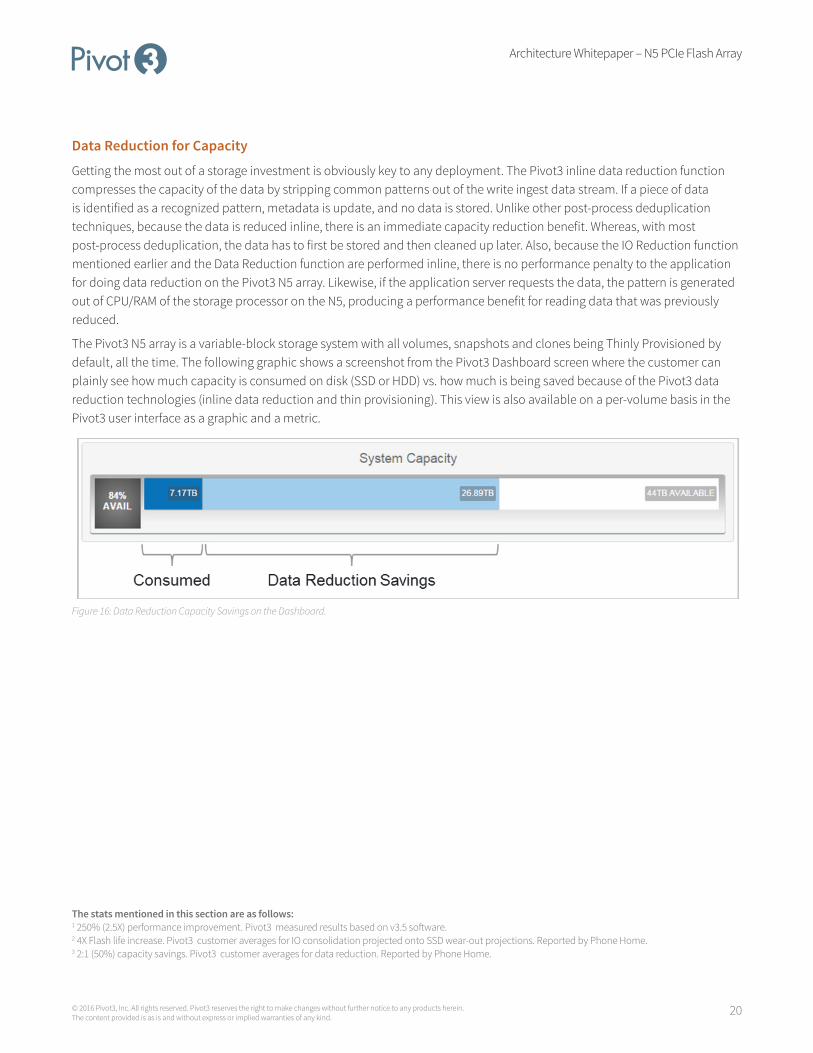
Getting the most out of a storage investment is obviously key to any deployment. The Pivot3 inline data reduction function compresses the capacity of the data by stripping common patterns out of the write ingest data stream. If a piece of data is identified as a recognized pattern, metadata is update, and no data is stored. Unlike other post-process deduplication techniques, because the data is reduced inline, there is an immediate capacity reduction benefit. Whereas, with most post-process deduplication, the data has to first be stored and then cleaned up later. Also, because the IO Reduction function mentioned earlier and the Data Reduction function are performed inline, there is no performance penalty to the application for doing data reduction on the Pivot3 N5 array. Likewise, if the application server requests the data, the pattern is generated out of CPU/RAM of the storage processor on the N5, producing a performance benefit for reading data that was previously reduced.
The Pivot3 N5 array is a variable-block storage system with all volumes, snapshots and clones being Thinly Provisioned by default, all the time. The following graphic shows a screenshot from the Pivot3 Dashboard screen where the customer can plainly see how much capacity is consumed on disk (SSD or HDD) vs. how much is being saved because of the Pivot3 data reduction technologies (inline data reduction and thin provisioning). This view is also available on a per-volume basis in the Pivot3 user interface as a graphic and a metric.
Figure 16: Data Reduction Capacity Savings on the Dashboard.
The stats mentioned in this section are as follows: 1 250% (2.5X) performance improvement. Pivot3 measured results based on v3.5 software. 2 4X Flash life increase. Pivot3 customer averages for IO consolidation projected onto SSD wear-out projections. Reported by Phone Home. 3 2:1 (50%) capacity savings. Pivot3 customer averages for data reduction. Reported by Phone Home.
Architecture Whitepaper – N5 PCIe Flash Array
21© 2016 Pivot3, Inc. All rights reserved. Pivot3 reserves the right to make changes without further notice to any products herein. The content provided is as is and without express or implied warranties of any kind.
Active-Active High Availability and Performance
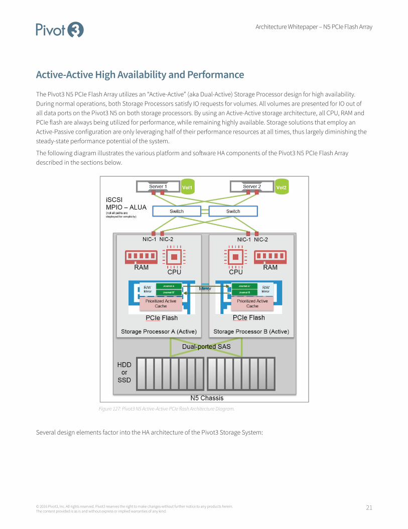
The Pivot3 N5 PCIe Flash Array utilizes an “Active-Active” (aka Dual-Active) Storage Processor design for high availability. During normal operations, both Storage Processors satisfy IO requests for volumes. All volumes are presented for IO out of all data ports on the Pivot3 N5 on both storage processors. By using an Active-Active storage architecture, all CPU, RAM and PCIe flash are always being utilized for performance, while remaining highly available. Storage solutions that employ an Active-Passive configuration are only leveraging half of their performance resources at all times, thus largely diminishing the steady-state performance potential of the system.
The following diagram illustrates the various platform and software HA components of the Pivot3 N5 PCIe Flash Array described in the sections below.
Figure 127: Pivot3 N5 Active-Active PCIe flash Architecture Diagram.
Several design elements factor into the HA architecture of the Pivot3 Storage System:

Architecture Whitepaper – N5 PCIe Flash Array
22© 2016 Pivot3, Inc. All rights reserved. Pivot3 reserves the right to make changes without further notice to any products herein. The content provided is as is and without express or implied warranties of any kind.
Item HA Implementation Description
Active-Active Storage Processors (SPs)
Dual-Redundant hot-swappable SPs per Pivot3 N5
An SP can be offline for any reason (maintenance, upgrade, failure, etc.) and the entire system operates on the remaining SP. The Active-Active SP design if leveraged for a variety of failover/failback use-cases (maintenance, upgrade, failure, etc.), and is managed seamlessly via the Pivot3 Storage user interfaces.
PCIe Flash Writes are mirrored across PCIe Flash cards
Data ingested into PCIe flash is mirrored for high availability and redundancy. Acknowledgement returned to host once both mirror copies are written.
SAS HDDs Dual-ported Enterprise SAS hard drives
Each SAS hard drive is connected to both SPs for high availability. In the event of a failover, the surviving SP is able to read/write to all HDDs.
SAS SSDs Dual-ported Enterprise SAS solid state drives
Each SAS solid state drive is connected to both SPs for high availability. In the event of a failover, the surviving SP is able to read/write to all SSDs.
MPIO MPIO ALUA with Round-Robin pathing policy
Utilizing the native host operating system MPIO stacks, multiple paths are connected to each volume for redundancy and performance. MPIO ALUA allows the Pivot3 N5 storage to instruct the host which paths are “optimized” for IO and which are “non-optimized”.
Data Ports Redundant Data Port NICs
MPIO paths are constructed from the host NICs to the Data Port NICs on the Pivot3 N5. Typically, on a host with 2-port iSCSI NIC and the 4x 10Gb NIC ports on the Pivot3 N5, there will be 8x MPIO paths to a volume. Four paths will be ALUA “optimized” and four paths will be ALUA “non-optimized”.
Power Supplies Dual-Redundant Hot-plug Power Supplies
The Pivot3 N5 chassis comes with two independent power supplies. The entire chassis can be powered via a single power supply. In the event a power supply fails, the chassis operates on the single remaining power supply until the faulty one is replaced.
Fans 12 Redundant Variable-Speed Fans (6 per SP)
Each storage processor has 6x variable-speed fans installed. In the event a fan fails, the system automatically increases the RPMs of the remaining fans until the failed fan can be replaced.
Table 11: High Availability components of the Pivot3 N5.
The HA function of the Pivot3 N5 product is always-on. Normal operational mode of the Pivot3 N5 is in the “Active-Active” state where both SPs are servicing IO for volumes. Typically, volumes are load-balanced across both Storage Processors to provide for optimal performance and capacity layout. In the event that an SP is offline, the surviving SP will take on IO operations for all volumes.
From a host perspective, a volume is “owned” by one storage processor at a time. Hosts connect to the volumes with MPIO ALUA (Asymmetric Logical Unit Assignment) in order for the Pivot3 N5 to instruct the operating system on which paths to prefer for IO (“optimized” paths. The recommended MPIO policy for connecting to volumes on the Pivot3 N5 is the “Round- Robin” policy. Most modern operating systems today have native MPIO stacks that support MPIO ALUA and Round-Robin MPIO Policies.
The following screenshot shows a volume connected to an ESX host with MPIO ALUA (VMW_SATP_ALUA) and the “Round Robin (VMware)” path selection policy.

Architecture Whitepaper – N5 PCIe Flash Array
23© 2016 Pivot3, Inc. All rights reserved. Pivot3 reserves the right to make changes without further notice to any products herein. The content provided is as is and without express or implied warranties of any kind.
Figure 138: MPIO ALUA setup on ESX host.
Management
Management of a storage system should be simple, straight-forward and flexible. Let’s face it, most IT administrators are stretched thin and can’t dedicate time for managing their storage systems on a day-to-day basis. With that in mind, the Pivot3 storage management architecture is one that is built on the latest technologies so that customers can manage their storage simply while in the context of their applications.
The Pivot3 storage management architecture is based on a secure RESTful API transport with JSON payloads. Based on this management architecture, there are three customer-facing management interfaces that can be used to manage the Pivot3 N5:
• A web-interface is instantiated on the Pivot3 N5 itself and can be accessed via your favorite web-browser (including mobile).
• A CLI client is available for Windows and Linux hosts.
• A vCenter plug-in is available for integrated vSphere management.
Accessing the web-UI is as simple as pointing your web-browser to one of the management ports of the Pivot3 N5.

Architecture Whitepaper – N5 PCIe Flash Array
24© 2016 Pivot3, Inc. All rights reserved. Pivot3 reserves the right to make changes without further notice to any products herein. The content provided is as is and without express or implied warranties of any kind.
Figure 149: Pivot3 Storage Web Interface.
The CLI is a powerful tool used for automation and scripting of common storage management tasks.
Figure 20: Pivot3 Storage Command Line Interface.
Architecture Whitepaper – N5 PCIe Flash Array
25© 2016 Pivot3, Inc. All rights reserved. Pivot3 reserves the right to make changes without further notice to any products herein. The content provided is as is and without express or implied warranties of any kind.
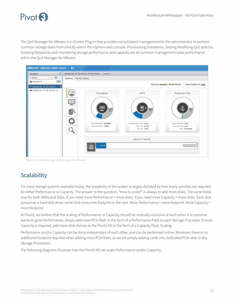
The QoS Manager for VMware is a vCenter Plug-in that provides consolidated management for the administrator to perform common storage tasks from directly within the vSphere web console. Provisioning Datastores, Setting/Modifying QoS policies, Growing Datastores and monitoring storage performance and capacity are all common management tasks performance within the QoS Manager for VMware.
Figure 21: Pivot3 Storage QoS Manager for VMware.
Scalability
For most storage systems available today, the scalability of the system is largely dictated by how many spindles are required for either Performance or Capacity. The answer to the question, “How to scale?” is always to add more disks. The same holds true for both HDDs and SSDs. If you need more Performance = more disks. If you need more Capacity = more disks. Each disk consumes a hard disk drive carrier that consumes footprint in the rack. More Performance = more footprint. More Capacity = more footprint.
At Pivot3, we believe that the scaling of Performance or Capacity should be mutually exclusive of each other. If a customer wants to grow Performance, simply add more PCIe flash in the form of a Performance Pack to each Storage Processor. If more Capacity is required, add more disk shelves to the Pivot3 N5 in the form of a Capacity Pack. Scaling
Performance and/or Capacity can be done independent of each other, and can be performed online. Moreover, there is no additional footprint required when adding more PCIe flash, as we are simply adding cards into dedicated PCIe slots in the Storage Processors.
The following diagrams illustrate how the Pivot3 N5 can scale Performance and/or Capacity.

Architecture Whitepaper – N5 PCIe Flash Array
26© 2016 Pivot3, Inc. All rights reserved. Pivot3 reserves the right to make changes without further notice to any products herein. The content provided is as is and without express or implied warranties of any kind.
Figure 22: PCIe Flash Scalability Figure 23: Storage Capacity Scalability
Adding Performance Packs to the system is an online event. Installing the Performance Pack involves adding additional PCIe flash cards to each Storage Processor. In order to do this we leverage the Active-Active HA function of the product to take each SP offline independently. For instance, SPA is taking offline to install the PCIe flash card and the system fails over to SPB and continues to service all volumes for IO. The same is done for SPB to install the PCIe flash card.
Adding Capacity Packs to the system is also an online event. Installing the Capacity Pack involves connecting additional disk shelves to the Pivot3 N5 chassis via SAS cables. Once connected, the additional capacity is added to the existing storage pools online with no interruption to volume availability.
The following table summarizes the Performance and Capacity scalability of each Pivot3 N5 model.
Model TypePCIe Flash Capacity
PCIe Flash Upgrade
Disk Capacity Scalability Disk Upgrade
N5-200 Hybrid Base: 2TB
Max: 7.2TB
Online (PCIe Flash Add)
Base: 32TB HDD
Max: 128TB HDD
Online (Pool Expansion)
N5-300 Hybrid Base: 2.6TB
Max: 7.8TB
Online (PCIe Flash Add)
Base: 64TB HDD
Max: 256TB HDD
Online (Pool Expansion)
N5-500 Hybrid Base: 5.2TB
Max: 10.4TB
Online (PCIe Flash Add)
Base: 64TB HDD
Max: 256TB HDD
Online (Pool Expansion)
N5-1000 Hybrid Base: 10.4TB
Max: 15.6TB
Online (PCIe Flash Add)
Base: 64TB HDD
Max: 256TB HDD
Online (Pool Expansion)

Architecture Whitepaper – N5 PCIe Flash Array
27© 2016 Pivot3, Inc. All rights reserved. Pivot3 reserves the right to make changes without further notice to any products herein. The content provided is as is and without express or implied warranties of any kind.
Model TypePCIe Flash Capacity
PCIe Flash Upgrade
Disk Capacity Scalability Disk Upgrade
N5-1500 All-flash Base: 2.6TB
Max: 2.6TB
N/A Base: 15TB SSD
Max: 60TB SSD
Online (Pool Expansion)
N5-3000 All-flash Base: 2.6TB
Max: 2.6TB
N/A Base: 30TB SSD
Max: 60TB SSD
Online (Pool Expansion)
Table 12: Performance and Capacity Scalability options.
ConclusionThe Pivot3 Storage Architecture is designed to help customers achieve their desire to manage data based on business value and priorities of the data. By implementing a storage architecture designed specifically around PCIe flash and storage QoS and Service Levels, Pivot3 allows customers to instruct the storage system about the value of their data. The Pivot3 N5 PCIe Flash Array automatically manages the IO prioritization based on the customer inputs.
The Dynamic Data Path manages the data in real-time making decisions based on QoS performance policies to ensure the data resides in the appropriate location (RAM, PCIe Flash, HDD, SSD), at the appropriate time. The Prioritized Active Cache is populated with the most valuable data based on QoS priorities in order to fulfill the performance targets for the volumes.
The Active-Active PCIe flash architecture is optimized for High Availability and Performance. Simple and flexible management allows a customer to manage the Pivot3 N5 PCIe Flash Array easily and with a minimal learning curve. Finally, being able to scale Performance and Capacity independently of each other provides the best value to the customer.