N5 Cover 8.5' x 11' - Vickers | Eaton | Char-Lynn | гидравлика ... · · 2005-07-12Bore...
30
HYDRO-LINE, INC. N5 Series Cylinders Heavy-Duty NFPA Interchangeable R O C K F O R D , I L
-
Upload
nguyenliem -
Category
Documents
-
view
219 -
download
2
Transcript of N5 Cover 8.5' x 11' - Vickers | Eaton | Char-Lynn | гидравлика ... · · 2005-07-12Bore...

HYDRO-LINE, INC.
N5 SeriesCylindersHeavy-Duty NFPAInterchangeable
RO
CKFORD, IL

Feature Description SymbolRod Diameter Specify in inches (2 position decimal) –
Cushions Noncushioned NCushioned both ends BCushioned head end HCushioned cap end C
Stroke Specify in inches (2 position decimal) –Bore Specify in inches (2 position decimal) –
Double Rod Include ONLY for double-rod cylinder DMounting Side lugs, MS2 A
Style Side tapped, MS4 BCap fixed clevis, MP1 CCap spherical bearing CSCap detachable clevis, MP2 DCSide end lugs, MS7 EHead rectangular flange, MF1 FHead rectangular, ME5 GCenter-line lugs, MS3 HHead square flange, MF5 JNo mount KAll tie rods extended, MX1 LHead end tie rods extended, MX3 MCap end tie rods extended, MX2 NCap rectangular, ME6 PCap rectangular flange, MF2 RCap square flange, MF6 SIntermediate fixed trunnion, MT4 TTHead trunnion, MT1 UCap trunnion, MT2 W
Model Series Hydraulic high pressure N5Air heavy duty AN5Air heavy duty prelubricated LAN5
Rod End Male, large 1Style Male, large, extended 1X
Male, small (standard) 2Male, small, extended 2XMale modified 2MFemale 4Female modified 4MPlain end 5Male, full rod diameter 6Male, for rod end coupling 10Modified M
Ports NPTF N†SAE S*SAE #12, standard for 31/4”, 4” and 5” bore cylinders TManifold MFlange FBSP/G GSpecial X
Rod Seals Urethane Ultra-Seal HCarboxylated lip type NPolyPak P‡Viton PolyPak F‡Viton lip type VUltra-Seal with scraper JNitrile lip type with scraper S‡Viton PolyPak with scraper G‡Viton lip type with scraper USpecial X
Piston Seals Carboxylated lip type NLow friction PolyPak DPolyPak PCast iron rings R‡Viton lip type VLow breakaway Teflon radial seal with wearband BSpecial X
Port Locations Head end positions 1-4Special XCap end positions 1-5Special X
Special Include ONLY if special modifications are required. XModifications Air bleeders Rod boots
Drainbacks Indicator switchesSpecial seals Four rod end flatsNonstd. mount Port or cushionOversize ports modificationsBronze bushings Double-end rod withKey Plate different rod endsStainless steel rod Special paint/platingStop tube
How to Order an N5 CylinderHydro-Line standard cylinders can be completely and accurately identified with a model number that encodesconstruction specifications. To develop the model number for ordering a cylinder, see the following example:
HOW TO ORDER1. Quantity2. Model number3. Special modifications
if required4. Completed
Application Data Sheet(s) (page 8) if required.
5. Required ship date
* To order standard SAE #12 ports on 31/4”, 4” and 5” bore, use T.† To order oversize SAE #16 ports on 31/4”, 4” and 5” bore, use S.‡ Consider specifying pinning the piston to the piston rod for temperatures
over 250˚ F.
24
3
1
Port LocationsPort location 5 is on thecenter of the back face ofthe end cap.
2
N5KD - 3.25 X 8.00 - N - 1.38 -- 2 - T - H - R - 1 - 1 - X
Customer Number (if desired)Hydro-Line Serial Number
HYDRO-LINE, INC.ROCKFORD, IL
NN55KKDD--33..2255 XX 88..0000--NN--11..3388--22--TT--HH--RR--11--11--XX119944001111223344--11AA1111557799--337755

N5 Design FeaturesHeavy Duty Rod Cartridge• Machined from gray iron for max-
imum bearing support and wearresistance
• Unitized, threadless assembly ispilot fitted into the head on a pre-cision bored diameter to assuretrue concentricity (See Fig. 3-1)
Piston Seals• Step cut iron piston rings standard
on N5• Nitrile lip-type seals standard on AN5
and LAN5• Viton lip seals available for special
fluid compatibility or temperaturesto 400˚F
• Special seals for high speed, lowfriction and other requirementsare available
Long Life Urethane RodSeals• Urethane “Ultra-Seal” standard
through 8” rod diameters on N5cylinders providing the optimum inlong life and sealing up to 200˚F(see Fig. 3-3)
• Viton PolyPak seals available on N5for special fluids or temperaturesto 400˚F
• Nitrile lip-type seals standard onAN5 and LAN5
• Special seals available
Double-Lipped Rod Wiper• Carboxylated double-lipped rod
wiper removes foreign materialsfrom the exposed rod to extendrod seal life
• The standard rod wiper is carboxylated material through51/2”; Viton for 7” through 10”diameter rods
• Metallic rod scraper and low friction
wipers available
SAE Ports• SAE ports standard on N5;
NPTF ports available at noextra charge
• NPTF ports standard onAN5 and LN5; SAE portsavailable at no extra charge
• Metric, BSP, Manifold,
Flange and other portingoptions available
Teflon Tube Seals• Superior design to prevent
leakage• Compatible with virtually all
fluids
A
B
C
E F
B
G
H
J
Fig. 3-1
F
Key FeaturesUnitized Rod CartridgeConstruction• The unitized construction contains all
cartridge seals in one assembly.• Standard removable retainer allows
cartridge removal with hex wrench withoutloosening the tie rods.
• See Page 5 for exceptions.
Sculptured Floating CushionsSelf-centering cushions are sculptured toallow the cylinder driving force and load tobe absorbed gradually and smoothly overthe entire cushion length maintaining nearconstant pressure. Refer to pages 20 and21 to determine your specific cushionrequirements
I
3
Urethane Ultra-Seal Rod SealHydro-Line’s Ultra-Seal Rod Seal provides much longer wearlife than conventional rod seals. Special urethane formulation allows superior resistance to abrasion, tearingand extrusion. The balanced radial cross-sectional designwith back-beveled sealing lips provides excellent low pressuresealability. Higher pressures energize the sealing lipsincreasing the contact stress profile and giving the addedsealing needed at increased pressures.
Fig. 3-2 Fig. 3-3
D

SpecificationsBore Sizes: 11/2” through 30”Pressure Ratings: N5 – 3000 psi hydraulic – nominal
AN5, LAN5 – 250 psi airSee page 23 for specific pressure ratingsand safety factors
Temperature: -40˚F to 200˚F standardNFPA interchangeable mountingsN5: Hydraulic cylinders incorporate urethane Ultra-Seal rod
seals, carboxylated double-lipped rod wipers, cast ironpiston rings, honed steel tubing I.D. and SAE ports.
AN5: Pneumatic cylinders incorporate carboxylated lip-typerod seals, carboxylated double-lipped rod wipers, carboxylated piston seals, .0003/.0005” thick chromeplated tube I.D. and NPTF ports.
LAN5: Pneumatic cylinders incorporate all AN5 features, andare also permanently lubricated at assembly by fillingthe piston and rod seals “V” groove with molybdenum disul-fide grease.
Floating Cap CushionInsert• Floating design allows closer
tolerance, yet minimum wear (seeFig. 3-2)
• Replaces ball check to providegreater flow area for fast breakaway
Captive Cushion Adjustment• Inner hex allows safe cushion
adjustment under pressure• Fine threads and special tip
design allows for precise adjustmentover a broad range of operatingconditions
Damage Resistant Piston Rod• 5/8” through 41/2” diameters use
90,000 to 100,000 minimum psiyield steel, case hardened andhard chrome plated
• Over 5” diameter uses 41,000 to80,000 psi yield steel, hardchrome plated
• All rods polished to 8-14 microinch finish for long seal life
• 17-4 PH stainless steel and othermaterials also available
Studded Piston Rod End• Roll threaded 125,000 minimum
psi yield steel• Greater strength and fatigue
resistance• Standard on 5/8”, 1” and 13/8”
diameter rods in styles 1, 1X, 2and 2X
• Available on 13/4”, 2” and 21/2”rods in styles 1, 1X, 2 and 2Xupon request
G I
J
K
L
ACK
L
Precision Steel Heads and Caps• Provides truly flat and parallel
mounting surfaces• Insures correct alignment of tube
and rod cartridge
Self Centering HeadCushion• Floating design allows closer
tolerances, yet minimum wear(see Fig. 3-2)
• Sculptured shape provides constantdeceleration curve
• Large size ball check provided athead end for fast breakaway
D
E
I
4
H

Metallic Rod ScrapersA Metallic Rod Scraper providesincreased rod seal life by removingabrasive contamination from therod in severe applications.
Special Rod EndsModifications of standard rod ends or completely special rodend styles are available to meet unique rod end connection requirements. (See page 29.)
Special PortsMetric, BSP, Manifold and other porting options are availableto meet specific requirements. (See page 22.)
Extra Heavy Chrome Tubes and RodsAdded wear and corrosion resistance are available by spec-ifying Extra Heavy Chrome (.002" to .003" thick).
Electronic FeedbackA complete line of precision cylinder position sensing andfeedback devices are available. These packaged cylindersystems can handle virtually any application requiring feed-back throughout the cylinder stroke — pneumatic orhydraulic, large or small bore, long or short strokes, with orwithout velocity monitoring — with resolutions of ± 0.001" orbetter. (See the Hydro-Line Systems Catalog.)
Stainless Steel Piston RodsPiston rods in 300 and 400 series, 17-4 PH, and others areavailable for those applications requiring increased corrosionresistance.
Special Coating and PaintingCylinders can be prepared with a primer coat, epoxy, lacquer, orenamel paint finish coatings to customer specifications.Synergistic, Nitrocarburizing and other material treatmentsare also available for special applications.
PlatingElectroless Nickel, Cadmium and other plating finishes areavailable for corrosive, washdown, pharmaceutical andother applications.
Special MaterialsBronze rod cartridges, brass, aluminum and composite tubing,complete stainless steel cylinders or other special materialsare available to meet most unique material requirements.
Low Breakaway PistonA low breakaway piston reducesrunning friction and metal-to-metalcontact by utilizing a bronze-filledTeflon wearband and a bi-directional,O-ring energized, bronze-filledTeflon piston seal.
WearbandsWearbands fitted to the pistonand/or rod cartridge eliminatemetal-to-metal contact on the piston/tube I.D. and the cartridge/rod O.D. Bronze-filled Teflonwearband material reduces frictionand wear in applications whereside-load is present.
Air Bleeders1/8" NPTF bleeders are located inthe tube or in the head and capwhen specified. SAE #2 bleederslocated in the head and cap arealso available when specified. Allbleeders may be located in positions1, 2, 3 or 4.
Rod BootsA rod boot surrounds the pistonrod with an external, expandablecover to protect the rod surfacefrom external contamination.Requires additional rod lengthwhich is determined by the cylinderstroke.
N5 Series Standard Design Options
Table Of ContentsHow to Order ....................................................................page 2N5 Design Features.....................................................pages 3-4N5 Standard Design Options............................................page 5N5 Cylinder Types .........................................................page 6-7Quality Statement .............................................................page 7N5 Custom Cylinders........................................................page 7Application Data Sheet .....................................................page 8
N5 Mounting Application Data ..........................................page 9N5 Mounting Dimensions ........................................pages 10-17Technical Data .........................................................pages 18-23Cylinder Mounting Accessories ...............................pages 23-27Warranty .........................................................................page 26Oversized Rods ..............................................................page 28Rod End Styles...............................................................page 29
5
ABS ApprovedHydro-Line is accepted under theEquipment Type Approval Programof the American Bureau of Shipping,and is the preferred source of manycustomers with requirements for ABSApproval. Steering applications mustbe specified to obtain appropriateprice and delivery.

6
N5 Series Cylinder Types
Back-to-Back CylindersBack-to-back cylinders are two single rod cylinders mountedtogether at the caps. Combinations of positions are possiblethrough various combinations of piston actuation. Consult Hydro-Line for maximum operating pressure.
Spring Return/Extend CylindersSpring return/extend cylinders provide thrust in one direction only(can be either direction). One port is used for pressure to actagainst the load while the inactive port is vented. An internal springis used to return the cylinder to its normal position.
Pumping UnitsPumping units consist of a standard hydraulic cylinder coupledwith a volume displacing lance cylinder via tie-bars. Special sealsand lance surface treatments are available to provide compatibili-ty with resins and chemicals used in the pumping process. Singleand double ended designs are available.
Systems CylindersSystems cylinders integrate position sensing and control valvesto produce a complete servoactuator package. Hydro-Line’sunique HLT In-Cylinder magnetostrictive feedback sensor providesa compact, robust package. External magnetostrictive (with protec-tive covers) or internally mounted linear potentiometer transduc-ers provide additional options. Valve, manifold blocks and a vari-ety of servocontrol valves may be added to yield a complete con-trol solution. (See Hydro-Line’s Systems Catalog for more informa-
Multiple Position CylindersMultiple position cylinders are similar to tandem cylinders (exceptthat the piston and rod assemblies are not connected) in that theoutput force is increased. Additionally, they may act as a precisionmultiple positioning device by actuating each cylinder successivelyor independently. Consult Hydro-Line for maximum operating pressure.
Single/Double Acting CylindersStandard R5 & A5 Series cylinders are double acting, with fluidpower driving the piston in both directions. Single acting cylin-ders have fluid power driving the piston in one direction, relyingon either the load or an external force to return the piston afterthe pressure is released.
Double End Cylinders Back-to-BackDouble end cylinders mounted back-to-back have common pistonrod and tie rods and the same stroke length. Consult Hydro-Linefor maximum operating pressure.
Tandem CylindersTandem cylinders consist of two cylinders interconnected (pistonand rod assemblies are connected). Pressure can act on twoeffective piston areas allowing the cylinder to be used as a forcemultiplier. This type of cylinder can also be used in air/oil systemsto provide smooth, metered flow because of equal volumes inone chamber of both cylinders. Consult Hydro-Line for maximumoperating pressure. NOTE: Front cylinder stroke is 1/8" longer atfront cylinder when strokes are the same.
Adjustable Stroke CylindersAdjustable stroke cylinders are furnished with a stroke adjustingscrew in the cap end of the cylinder. Adjusting this screw in or outlimits the retract stroke to the precise length desired.
Non-Rotating CylindersNon-rotating cylinders are furnished with internal guide rodswhich prevent piston rod rotation throughout the stroke.Rotational torque and stroke length determine the amount anddiameter of the guide rods.
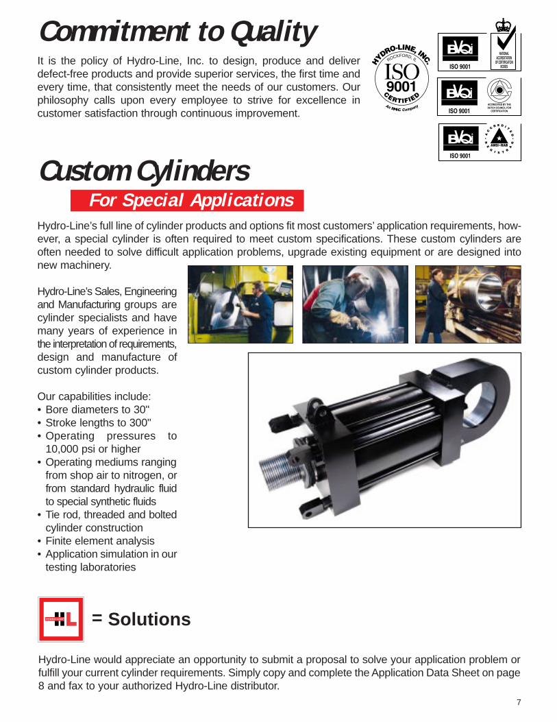
Hydro-Line’s full line of cylinder products and options fit most customers’ application requirements, how-ever, a special cylinder is often required to meet custom specifications. These custom cylinders areoften needed to solve difficult application problems, upgrade existing equipment or are designed intonew machinery.
Hydro-Line’s Sales, Engineeringand Manufacturing groups arecylinder specialists and havemany years of experience inthe interpretation of requirements,design and manufacture ofcustom cylinder products.
Our capabilities include:• Bore diameters to 30"• Stroke lengths to 300"• Operating pressures to
10,000 psi or higher• Operating mediums ranging
from shop air to nitrogen, orfrom standard hydraulic fluidto special synthetic fluids
• Tie rod, threaded and boltedcylinder construction
• Finite element analysis• Application simulation in our
testing laboratories
7
Custom CylindersFor Special Applications
Hydro-Line would appreciate an opportunity to submit a proposal to solve your application problem orfulfill your current cylinder requirements. Simply copy and complete the Application Data Sheet on page8 and fax to your authorized Hydro-Line distributor.
= Solutions
Commitment to QualityIt is the policy of Hydro-Line, Inc. to design, produce and deliverdefect-free products and provide superior services, the first time andevery time, that consistently meet the needs of our customers. Ourphilosophy calls upon every employee to strive for excellence in customer satisfaction through continuous improvement.
ROCKFORD, IL

8FRM-24-005
Hydro-Line Application Data Sheet
PREPARED BY: DATE: REVIEWED BY: DATE:
CUSTOMER DRAWING NUMBER: REVISION DATES: HYDRO-LINE QUOTE NUMBER:
APPLICATION SKETCH: DESCRIPTION OF APPLICATIONOR SPECIAL REQUIREMENT:
WHAT INDUSTRY IS THE CYLINDER WHAT TYPE OF MACHINE IS THE WHAT IS THE CYLINDER NAMEUSED IN? CYLINDER USED ON? THE APPLICATION?
WHAT IS THE PRESENT PROBLEM?
WHAT IS THE PRESENT CYLINDER TYPE AND MODEL NUMBER?
WHAT ENVIRONMENTAL CONDITIONS IS THE CYLINDER SUBJECTED TO?
Standard Factory Corrosive Washdown Chemical Outdoors Other
WHAT IS THE MOUNTING?Attitude Rod End Connection Kno wn Side LoadVertical Angle Horizontal Firmly Guided
Degrees From Vertical Supported lbs.Rod Up Rod Up Unsupported Rod Down Rod Down
WHAT IS THE OPERATING ENVIRONMENT?Fluid Media Operating Pressure Temperature at CylinderAir Minimum psi Minimum °FOil Typical psi Typical °FOther Maximum psi Maximum °FFluid Type
WHAT IS THE WORK BEING PERFORMED?Load Rod Speed Cycles per Min ute
Push lbs. Extend in./sec.
Pull lbs. Retract in./sec. (in and out)
Company Name:
Contact:
Phone Number: Fax Number:
Distributor Name:
Contact:
Phone Number: Fax Number: ______________
Model Numbering System
STAINLESS STEELSTOP TUBE LENGTH TRUNNION XI DIMENSION ROD TYPE
HEAD CAP
DOUBLE END ADDITIONAL NEEDLE MODELROD STYLE ROD LENGTH LOCATION 4-FLAT PREFIX
MODEL/SERIES MOUNT BORE STROKE CUSHION ROD DIA ROD STY PORTS ROD PSTN H C MODEL
• • •
QUANTITY
C C
Please fill in all available information above. Refer to the Hydro-Line Model Numbering System on Pages 2.
SEALS PORT LOC

Head RectangularFlange F MF1 11/2" - 8"Cap Rectangular Flange R MF2 11/2" - 8"Head Square Flange J MF5 11/2" - 8"Cap Square Flange S MF6 11/2" - 8"Integral Square Head J ** 10" - 30"Integral Square Cap S ** 10" - 30"Tie Rods Extended L, N, M MX1, MX2, 11/2" - 8"
MX3Head Rectangular G ** ME5 11/2" - 14"Cap Rectangular P ** ME6 11/2" - 14"No Mount K N/A 11/2" - 30"
N5 Series Mounting Application Data
Side Lugs A MS2 11/2" - 8"
Side Tapped B MS4 11/2" - 8"
Center-Line Lugs H ** MS3 11/2" - 20"
Side End Lugs E MS7 11/2" - 8"
Cap Fixed Clevis C ** MP1 11/2" - 30"Cap SphericalBearing CS N/A 11/2" - 6"Detachable Clevis DC MP2 11/2" - 8"Head Trunnion U ** MT1 1" - 30"Cap Trunnion W ** MT2 11/2" - 30"IntermediateFixed Trunnion TT ** MT4 11/2" - 30"
Piston Securing MethodsPiston to rod joints are threaded, anaerobically sealed and secured, and staked (single rod ends). Under normal operatingconditions, additional securing is not necessary. However, in applications where: 1) temperatures exceed 250˚F, 2) pressurespike or impact shock is present, or 3) a piston previously detached, the piston should be pinned; this must be specifiedwhen ordering. Consult factory for other securing methods.
Double Rod CylindersDouble rod cylinders are available in all mountings except C, CS, DC, N, P, R, S and W. Use the basic dimensional information on page 15 combined with dimensions in the drawings on pages 10-15.
Mounting AccessoriesSee pages 23-27 for mounting accessories.
End MountingsThe head and cap rectangular mounts G and P should beused for hydraulic applications to avoid excessive deflectionwhich occurs on the F and R mountings.
Refer to the chart on page 10 for pressure ratings for Fmounts in push and R mounts in pull.
The G, P, J and S mounts are usable in both push and pullat full rated hydraulic pressures as shown on page 23.
End and Intermediate Pivot MountingsTrunnion and pivot pins are designed to carry shear loadsonly. Trunnion and pivot bearings must fit closely for theentire length of the pin. Hold the trunnion bearings rigidly andin accurate alignment.
** NFPA MOUNTING DIMENSIONS ARE AVAILABLE ON ALL CYLINDERS 1 1/2" - 8" BORE.FOR LARGER CYLINDERS, SEE PAGES 16-17 FOR MOUNTING DIMENSIONS.
9
Side and Center-Line MountingsThese mounts should be keyed or pinned to prevent shiftingduring operation. Keys or pins must be strong enough toresist the full thrust of the cylinder. The lugs on A and Hmounts are large enough to accommodate dowel pins.Extended key plates for stock and custom cylinder modelsare available when specified. Pin or key the head wheneverpossible. Do not pin or key both ends. Cylinders becomelonger when pressure is applied and tube will tend to buckle.
The alignment and center-line height on the E mount aremaintained by accurately machined surfaces on the headand cap which are held against the mounting surface by theend lugs.
DESCRIPTION HYDRO-LINEMOUNT
NFPADESIGNATION
N5 BORESAVAILABLE
DESCRIPTION HYDRO-LINEMOUNT
NFPADESIGNATION
N5 BORESAVAILABLE
DESCRIPTION HYDRO-LINEMOUNT
NFPADESIGNATION
N5 BORESAVAILABLE
11/2" - 8" bore cylinders
LB★
ZF ★
G J FH
Y•RODDIA.MMKK
AC
VF
K EE (2)
R
ESQ
TFUF
2 4
3
1
B
RM
FB‡ DFLATS
P •★
R
ESQ
TFUF
24
3
1
BFLATSD
FB‡
EE (2)RM
LB★
ZB★
G J K
Y•RODDIA.MMKK
A
VBFH
W
C
P •★
R
LB★
ZJ ★ ESQ
TFUF
G J
Y•K
2 4
3
1RODDIA.MM
KK
AC V
F B
RM
FB‡
St’d cushion adj. locationcap rectangular end.
DFLATS
EE (2)P •
★
EE (2)
R
LB★
ZB★
ESQ
TFUF
G J K
Y•
24
3
1 RODDIA.MMKK
AC V
FWFSt'd cushion
adj. locationhead retangular end.
BD
RM
FB‡FLATS
P •★
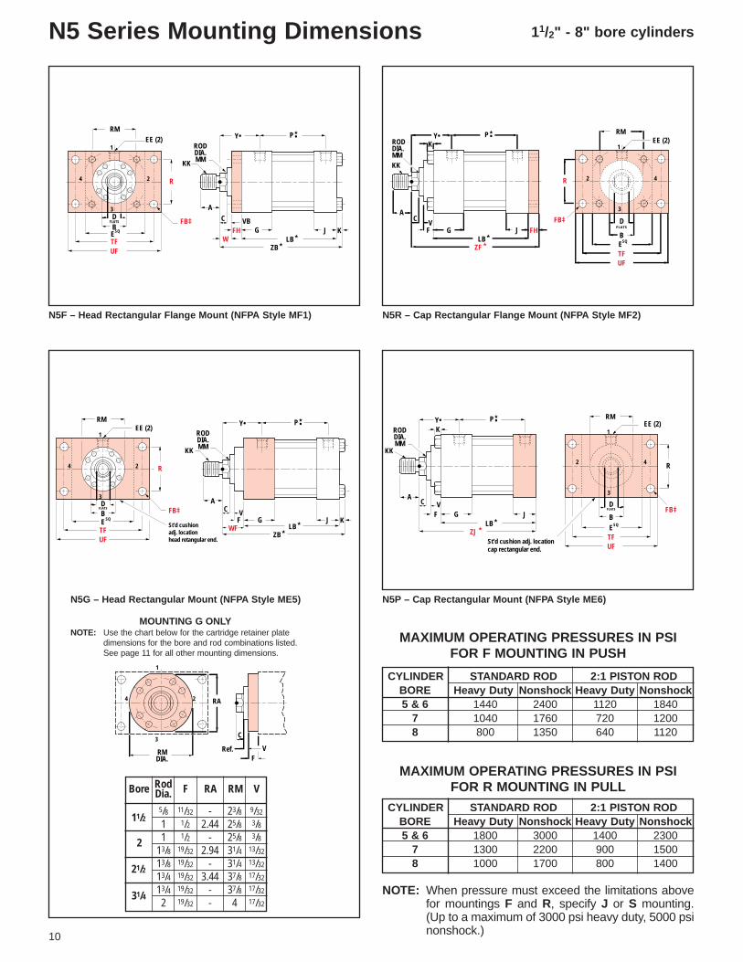
N5F – Head Rectangular Flange Mount (NFPA Style MF1) N5R – Cap Rectangular Flange Mount (NFPA Style MF2)
N5P – Cap Rectangular Mount (NFPA Style ME6)N5G – Head Rectangular Mount (NFPA Style ME5)
RA2
1
3
4
C
RMDIA.
Ref. VF
10
N5 Series Mounting Dimensions
5/8 11/32 - 23/8 9/32
1 1/2 2.44 25/8 3/81 1/2 - 25/8 3/8
13/8 19/32 2.94 31/4 13/32
13/8 19/32 - 31/4 13/32
13/4 19/32 3.44 37/8 17/32
13/4 19/32 - 37/8 17/32
2 19/32 - 4 17/32
MOUNTING G ONLYNOTE: Use the chart below for the cartridge retainer plate
dimensions for the bore and rod combinations listed.See page 11 for all other mounting dimensions.
CYLINDER STANDARD ROD 2:1 PISTON RODBORE Heavy Duty Nonshock Heavy Duty Nonshock5 & 6 1440 2400 1120 1840
7 1040 1760 720 12008 800 1350 640 1120
MAXIMUM OPERATING PRESSURES IN PSI FOR F MOUNTING IN PUSH
MAXIMUM OPERATING PRESSURES IN PSI FOR R MOUNTING IN PULL
NOTE: When pressure must exceed the limitations abovefor mountings F and R, specify J or S mounting.(Up to a maximum of 3000 psi heavy duty, 5000 psinonshock.)
CYLINDER STANDARD ROD 2:1 PISTON RODBORE Heavy Duty Nonshock Heavy Duty Nonshock5 & 6 1800 3000 1400 2300
7 1300 2200 900 15008 1000 1700 800 1400
Bore F RMRA VRodDia.
11/2
2
21/2
31/4

BORE 11/2 2 21/2 31/4 4 5 6 7 8
A 3/4 11/8 11/8 15/8 2 21/4 3 31/2 31/2
AA 2.3 2.9 3.6 4.6 5.4 7.0 8.1 9.3 10.6
AC 11/8 11/2 11/2 13/4 2 25/8 31/4 33/4 43/8
AD 5/8 15/16 15/16 11/16 15/16 111/16 115/16 27/16 211/16
AE 1/4 3/8 3/8 3/8 1/2 5/8 3/4 7/8 1
AF 3/8 11/16 11/16 7/8 11/8 13/8 13/4 21/4 21/2
B -.001
-.003BB 13/8 113/16 113/16 25/16 25/16 33/16 35/8 41/8 41/2
C 3/8 1/2 1/2 5/8 3/4 7/8 1 1 1
CC 1/2-20 7/8-14 7/8-14 11/4-12 11/2-12 13/4-12 21/4-12 23/4-12 31/4-12
D 17/32 7/8 7/8 11/8 11/2 13/4 21/8 25/8 3
DD 3/8-24 1/2-20 1/2-20 5/8-18 5/8-18 7/8-14 1-14 11/8-12 11/4-12
E 21/2 3 31/2 41/2 5 61/2 71/2 81/2 91/2
EE (SAE) 10 10 10 12 12 12 16 20 24
EE (NPTF) 1/2 1/2 1/2 3/4 3/4 3/4 1 11/4 11/2
F ▲ ▲ 1/2 19/32 19/32 19/32 19/32 23/32 23/32
FB‡ 7/16 9/16 9/16 11/16 11/16 15/16 11/16 13/16 15/16
FH 3/8 5/8 5/8 3/4 7/8 7/8 1 1 1
FT 5/8-18 1-14 1-14 13/8-12 13/4-12 2-12 21/2-12 3-12 31/2-12
G 13/4 13/4 13/4 2 2 2 21/4 23/4 3
J 11/2 11/2 11/2 13/4 13/4 13/4 21/4 23/4 3
K 3/8 7/16 7/16 9/16 9/16 13/16 15/16 1 11/8
KK 7/16-20 3/4-16 3/4-16 1-14 11/4-12 11/2-12 17/8-12 21/4-12 21/2-12
LB★ 45/8 45/8 43/4 51/2 53/4 61/4 73/8 81/2 91/2
MM 5/8 1 1 13/8 13/4 2 21/2 3 31/2
P★• 211/16 211/16 213/16 39/16 313/16 45/16 411/16 51/8 57/8
R 1.63 2.05 2.55 3.25 3.82 4.95 5.73 6.58 7.50
RM ■ ■ 25/8 31/4 37/8 4 47/16 51/4 55/8
TF 37/16 41/8 45/8 57/8 63/8 83/16 97/16 105/8 1113/16
UF 41/4 51/8 55/8 71/8 75/8 93/4 111/4 125/8 14
V ▲ ▲ 3/8 13/32 17/32 17/32 21/32 17/32 17/32
VB 1/4 1/4 1/4 1/4 1/4 1/4 1/4 1/4 1/4
W 5/8 3/4 3/4 7/8 1 11/8 11/4 11/4 11/4
WF 1 13/8 13/8 15/8 17/8 2 21/4 21/4 21/4
Y• 23/32 215/32 215/32 223/32 231/32 33/32 319/32 315/16 41/16
ZB★ 6 67/16 69/16 711/16 83/16 91/16 109/16 113/4 127/8
ZF★ 6 65/8 63/4 77/8 81/2 91/8 105/8 113/4 123/4
ZJ★ 55/8 6 61/8 71/8 75/8 81/4 95/8 103/4 113/4
ZT★ 7 713/16 715/16 97/16 915/16 117/16 131/4 147/8 161/4PISTON
THICKNESS
Dimensions shown in red are mounting dimensions.
NOTE: Additional port information on page 22.
Oversize rods affect dimensions in gray-shaded areas. See pages 28-29 for these dimensions.
★ Add stroke to all starred dimensions.
■ Refer to page 23.
NOTE: Overall length dimensions that require addition of stroke mayvary from dimensions shown, due to manufacturing tolerances.
▲ Use FH dimension in place of F dimension and VB dimension inplace of V dimension.
‡ Use screws 1/16" smaller than mounting holes.• Port dimensions for standard ports only. Consult Hydro-Line for
flange, manifold and special ports
LB★
ZF
G J
Y•
FH
RODDIA.MMKK
AC V
F
K
★
EE (2)
R
ER SQ
TF
TF
UFSQ
2 4
3
1
B
RM
DFLATS
FB‡
P •★
EE (2)
R
ER
SQ
TF
TF
UFSQ
24
3
1
BFLATSD
RM
FB‡
LB★
ZB★
GJ K
Y•
RODDIA.MMKK
A
C VBFH
W
P •★
EE (2)
ESQRB
D
AA
24
3
1
RM
FLATS
LB★
ZT★
G J
Y•RODDIA.MMKK
A
C VBFH
W
DD
BBBB
K
P •★
N5S – Cap Square Flange Mount (NFPA Style MF6)
N5J – Head Square Flange Mount (NFPA Style MF5)
N5K (No Mount), N5L (NFPA Style MX1), N5N (NFPA Style MX2),N5M (NFPA Style MX3) – Tie Rods Extended Mounts
End Mountings(See important application data on pages 18-19.)
Cylinder Dimensions
11
13/8 13/8 11/2 13/4 2 21/2 27/8 3 31/2
K – No Mount(MX1) L – Both tie rods extended(MX2) N – Cap end tie rods extended(MX3) M – Head end tie rods extended
NOTE: Mounting styles L and M use filler plate at thehead end when cylinder has circular retainer.
11/8 11/2 11/2 2 23/8 25/8 31/8 33/4 41/4
11/2" - 8" bore cylinders
EE (2)
ST
SS★
ZB★
ETSUS
SB‡
G J
Y•
K
XS
24
1
3
BD
FLATS
SQ
RM
SW
LB★
SU SU
RODDIA.MMKK
AC V
F
SW
P •★EE (2)
SN★
ZB★
E
TK
G J
Y•
K
XT
24
1
3
TN NT TAP
DFLATS
SQ
LB★
RODDIA.MMKK
AC V
F
B
RM
-.005-.010
E2
P •★
LB ★★
ZE
SE
★
ELEO
RODDIA.MMKK
A
W
G
K
C VBFH
Y•
★XE
J
2
E
BD
BL
FLATS
SQ
4
EE (2)1
3ET
EB‡
-.005-.010
E2
EG
DIA. COUNTERBORE2 HOLES HEAD END ONLYEF
1/64 APPROX.
RM P •★
ST
SS★
ZB★
ETSUS
SB‡ G J
Y•
K
XS
24
1
3
BD
FLATS
SQ
RM
-.005-.010
SW
LB★
SU SU
RODDIA.MMKK
AC
VF
SW
E2
EE (2)P •
★
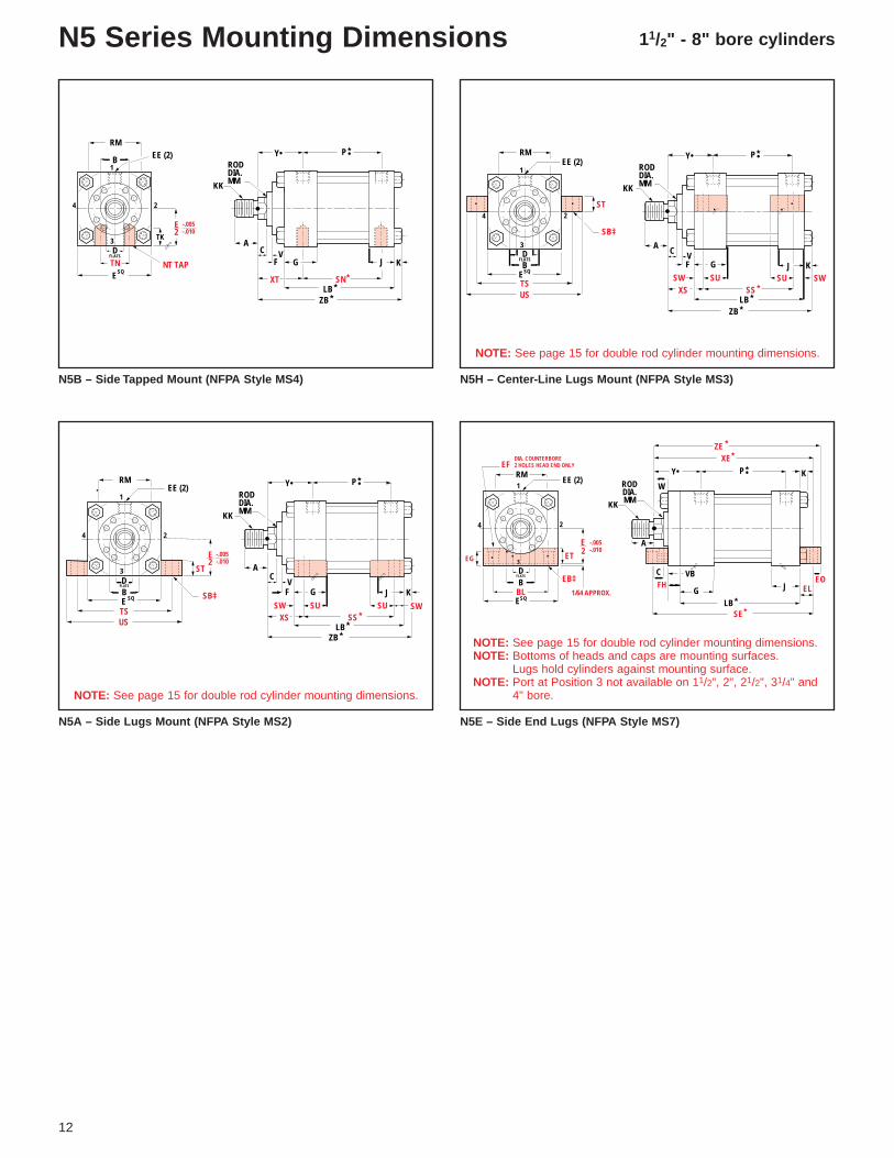
N5B – Side Tapped Mount (NFPA Style MS4) N5H – Center-Line Lugs Mount (NFPA Style MS3)
N5 Series Mounting Dimensions
N5A – Side Lugs Mount (NFPA Style MS2) N5E – Side End Lugs (NFPA Style MS7)
12
NOTE: See page 15 for double rod cylinder mounting dimensions.
NOTE: See page 15 for double rod cylinder mounting dimensions.
NOTE: See page 15 for double rod cylinder mounting dimensions.NOTE: Bottoms of heads and caps are mounting surfaces.
Lugs hold cylinders against mounting surface.NOTE: Port at Position 3 not available on 11/2", 2", 21/2", 31/4" and
4" bore.

13
★
P •★Y•
ZB
★LBG K
RODDIA.MMKK
A
FHE
24
1
3
BD
FLATS
SQ
RM
JW
VB-.013-.015
FH 2
C
EE (2)
N5 – Extended Key Plate – Available when specified
Side and Center-Line Mountings(See important application data on pages 18-19.)
Cylinder Dimensions
Dimensions shown in red are mounting dimensions.
NOTE: Additional port information on page 22.
Oversize rods affect dimensions in gray-shaded areas. See pages 28-29 for these dimensions.
★ Add stroke to all starred dimensions.
■ Refer to page 23.
NOTE: Overall length dimensions that require addition of stroke mayvary from dimensions shown, due to manufacturing tolerances.
▲ Use FH dimension in place of F dimension and VB dimension inplace of V dimension.
‡ Use screws 1/16" smaller than mounting holes.• Port dimensions for standard ports only. Consult Hydro-Line for
flange, manifold and special ports.
PISTONTHICKNESS
NOTE: To order, specify extended key plate after the N5 series andmounting style (Example: N5A with extended key plate).
BORE 11/2 2 21/2 31/4 4 5 6 7 8A 3/4 11/8 11/8 15/8 2 21/4 3 31/2 31/2
AC 11/8 11/2 11/2 13/4 2 25/8 31/4 33/4 43/8AD 5/8 15/16 15/16 11/16 15/16 111/16 115/16 27/16 211/16
AE 1/4 3/8 3/8 3/8 1/2 5/8 3/4 7/8 1AF 3/8 11/16 11/16 7/8 11/8 13/8 13/4 21/4 21/2
B-.001-.003BL 1.63 2.07 2.56 3.27 3.84 4.95 5.74 6.58 7.51C 3/8 1/2 1/2 5/8 3/4 7/8 1 1 1
CC 1/2-20 7/8-14 7/8-14 11/4-12 11/2-12 13/4-12 21/4-12 23/4-12 31/4-12D 17/32 7/8 7/8 11/8 11/2 13/4 21/8 25/8 3E 21/2 3 31/2 41/2 5 61/2 71/2 81/2 91/2
EB‡ 7/16 9/16 9/16 11/16 11/16 15/16 11/16 13/16 15/16
EE (SAE) 10 10 10 12 12 12 16 20 24EE (NPTF) 1/2 1/2 1/2 3/4 3/4 3/4 1 11/4 11/2
EF 5/8 13/16 13/16 1 1 13/8 15/8 15/8 23/32
EG 11/16 3/4 3/4 11/16 7/8 11/4 11/2 11/2 13/4EL 7/8 15/16 15/16 11/8 11/8 11/2 111/16 113/16 2EO 3/8 1/2 1/2 5/8 5/8 3/4 7/8 1 11/8ET 7/8 1 1 11/4 11/4 11/2 13/4 2 2F ▲ ▲ 1/2 19/32 19/32 19/32 19/32 23/32 23/32
FH 3/8 5/8 5/8 3/4 7/8 7/8 1 1 1FT 5/8-18 1-14 1-14 13/8-12 13/4-12 2-12 21/2-12 3-12 31/2-12G 13/4 13/4 13/4 2 2 2 21/4 23/4 3J 11/2 11/2 11/2 13/4 13/4 13/4 21/4 23/4 3K 3/8 7/16 7/16 9/16 9/16 13/16 15/16 1 11/8
KK 7/16-20 3/4-16 3/4-16 1-14 11/4-12 11/2-12 17/8-12 21/4-12 21/2-12LB★ 45/8 45/8 43/4 51/2 53/4 61/4 73/8 81/2 91/2MM 5/8 1 1 13/8 13/4 2 21/2 3 31/2NT 3/8-16 1/2-13 5/8-11 3/4-10 1-8 1-8 11/4-7 11/2-6 11/2-6P★• 211/16 211/16 213/16 39/16 313/16 45/16 411/16 51/8 57/8RM ■ ■ 25/8 31/4 37/8 4 47/16 51/4 55/8SB‡ 7/16 9/16 13/16 13/16 11/16 11/16 15/16 19/16 19/16
SE★ 63/4 71/8 71/4 81/2 87/8 101/8 113/4 131/8 141/2SN★ 27/8 27/8 3 31/2 33/4 41/4 51/8 57/8 65/8SS★ 37/8 35/8 33/8 41/8 4 41/2 51/8 53/4 63/4ST 1/2 3/4 1 1 11/4 11/4 11/2 13/4 13/4SU 15/16 11/4 19/16 19/16 2 2 21/2 27/8 27/8SW 3/8 1/2 11/16 11/16 7/8 7/8 11/8 13/8 13/8TK 9/16 1/2 13/16 3/4 1 11/8 15/16 21/8 19/16
TN 3/4 15/16 15/16 11/2 21/16 215/16 35/16 33/4 41/4TS 31/4 4 47/8 57/8 63/4 81/4 93/4 111/4 121/4US 4 5 61/4 71/4 81/2 10 12 14 15V ▲ ▲ 3/8 13/32 17/32 17/32 21/32 17/32 17/32
VB 1/4 1/4 1/4 1/4 1/4 1/4 1/4 1/4 1/4W 5/8 3/4 3/4 7/8 1 11/8 11/4 11/4 11/4
XE★ 61/2 615/16 71/16 81/4 83/4 93/4 115/16 129/16 133/4XS 13/8 17/8 21/16 25/16 23/4 27/8 33/8 35/8 35/8XT 2 23/8 23/8 23/4 3 31/8 31/2 313/16 315/16
Y• 23/32 215/32 215/32 223/32 231/32 33/32 319/32 315/16 41/16
ZB★ 6 67/16 69/16 711/16 83/16 91/16 109/16 113/4 127/8ZE★ 67/8 77/16 79/16 87/8 93/8 101/2 123/16 139/16 147/8
13/8 13/8 11/2 13/4 2 21/4 27/8 3 31/2
11/8 11/2 11/2 2 23/8 25/8 31/8 33/4 41/4

11/2" - 8" bore cylinders
J K
ZB★
G
Y•RODDIA.MMKK
AC
VF
LB★XG
TD24
EE (2)
EUT
TL
1
3
BD
FLATS
SQ
RM
TL
+.000-.001
P •★
TD
J K
ZB★
24
G
EE (2)
EUT
TL
1
3
BD
FLATS
SQ
RM
TL
Y•RODDIA.MM
KK
AC
VF
LB★
★XJ
+.000-.001
P •★
TD
J K
ZB★
24
G
EE (2)
EUM
TL
1
3
BD
FLATS
SQ
RM
TMTL
Y•RODDIA.MM
KK
A C
XI
VF
LB★
BD
Customer to Specify
UV +.000-.001
P •★
TD
J K
ZB★
24
G
EE (2)
EUM
TL
1
3
BD
FLATS
SQ
RM
TMTLY•
RODDIA.MM
KK
A C
XI
VF
LB★
BD
Customer to Specify
UV +.000-.001
P •★
EE (2)
MR
LRCD
M
K
LB★
E
CB†SQ
G J FH
Y•
L M
XD ★
2 4
CW CW
RODDIA.MM
A
KK
CV
F
1
3
FLATSD
25˚*
RMP •★
N5W – Cap Trunnion Mount (NFPA Style MT2) N5U – Head Trunnion Mount (NFPA Style MT1)
N5 Series Mounting Dimensions
N5TT – Intermediate Fixed Trunnion Mount (NFPA Style MT4) N5TT – Intermediate Fixed Trunnion Mount (NFPA Style MT4)
14
NOTE: 11/2" - 5" bores have one-piece trunnion.
✝ Maximum width of mating part.
NOTE: 6" - 8" bores have split trunnion.
N5DC – Cap Detachable Clevis Mount (NFPA Style MP2)
25˚*
EE (2)
MR
LRCD
M
K
LB★
ESQ
G J
Y•
L M
XC★
2 4
CW CW
RODDIA.MM
A
KK
CVF
1
3
FLATSD
RM
CB†
B
P •★
N5C – Cap Fixed Clevis Mount (NFPA Style MP1)
✝ Maximum width of mating part.

Dimensions shown in red are mounting dimensions.NOTE: Additional port information on page 22.
Oversize rods affect dimensions in gray-shaded areas. See pages 28-29 for these dimensions.★ Add stroke to all starred dimensions.■ Refer to page 23.NOTE: Overall length dimensions that require addition of stroke may vary from dimensions shown, due to
manufacturing tolerances.▲ Use FH dimension in place of F dimension and VB dimension in place of V dimension.★★ Plus 2 x stroke• Port dimensions for standard ports only. Consult Hydro-Line for flange, manifold and special ports.
EE (2)
MS
NR
CD
K
LB★
ESQ
G J
Y•
L
XC★
2 4
RODDIA.MM
A
KK
CVF
1
3
FLATSD
RM
EX
3˚
+.0000-.0005
3˚
LUBEFITTING
P •★
SV★
★
ZM + 2 x STROKE
Y•
ZL
XS
LD★
SU SU
GGE
24
1
3
BD
FLATS
SQ
RMEE (2) P •
★
15
N5AD – Side Lugs Mount – Double Rod
SX★
ZM + 2 x STROKE
ZL
XT
LD★
★
N5BD – Side Tapped Mount – Double Rod
LD★
★
ZM + 2 x STROKE
SP
★XX
EL ELEOEO
N5ED – Side End Lugs Mount – Double Rod
NOTE: N5HD has mounting dimensions identical to N5AD.NOTE: Add D for double end after the N5 series and mounting style.
(Example: N5AD)NOTE: Dimensions not shown are same as single rod cylinders.NOTE: Double rod cylinders available in all mounts except C, DC and W.
Pivot Mountings and Double Rod Cylinders(See important application data on pages 18-19.)
Cylinder Dimensions
N5CS – Cap Spherical Bearing Mount
BORE 11/2 2 21/2 31/4 4 5 6 7 8A 3/4 11/8 11/8 15/8 2 21/4 3 31/2 31/2
AC 11/8 11/2 11/2 13/4 2 25/8 31/4 33/4 43/8AD 5/8 15/16 15/16 11/16 15/16 111/16 115/16 27/16 211/16
AE 1/4 3/8 3/8 3/8 1/2 5/8 3/8 7/8 1AF 3/8 11/16 11/16 7/8 11/8 13/8 13/4 21/4 21/2
B-.001-.003
BD 11/2 11/2 11/2 2 2 21/2 3 3 31/2C 3/8 1/2 1/2 5/8 3/4 7/8 1 1 1
CB 3/4 11/4 11/4 11/2 2 21/2 21/2 3 3CC 1/2-20 7/8-14 7/8-14 11/4-12 11/2-12 13/4-12 21/4-12 23/4-12 31/4-12CD 1/2 3/4 3/4 1 13/8 13/4 2 21/2 3CW 1/2 5/8 5/8 3/4 1 11/4 11/4 11/2 11/2D 17/32 7/8 7/8 11/8 11/2 13/4 21/8 25/8 3E 21/2 3 31/2 41/2 5 61/2 71/2 81/2 91/2
EE (NPTF) 1/2 1/2 1/2 3/4 3/4 3/4 1 11/4 11/2EE (SAE) 10 10 10 12 12 12 16 20 24
EL 7/8 15/16 15/16 11/8 11/8 11/2 111/16 113/16 2EO 3/8 1/2 1/2 5/8 5/8 3/4 7/8 1 11/8EX 7/16 21/32 21/32 7/8 13/16 117/32 13/4 – –F ▲ ▲ 1/2 19/32 19/32 19/32 19/32 23/32 23/32
FH 3/8 5/8 5/8 3/4 7/8 7/8 1 1 1FT 5/8-18 1-14 1-14 13/8-12 13/4-12 2-12 21/2-12 3-12 31/2-12G 13/4 13/4 13/4 2 2 2 21/4 23/4 3J 11/2 11/2 11/2 13/4 13/4 13/4 21/4 23/4 3K 3/8 7/16 7/16 9/16 9/16 13/16 15/16 1 11/8
KK 7/16-20 3/4-16 3/4-16 1-14 11/4-12 11/2-12 17/8-12 21/4-12 21/2-12L 3/4 11/4 11/4 11/2 21/8 21/4 21/2 3 31/4
LB★ 45/8 45/8 43/4 51/2 53/4 61/4 73/8 81/2 91/2LD★ 47/8 47/8 5 53/4 6 61/2 73/8 81/2 91/2LR 9/16 11/16 11/16 11/4 17/8 115/16 21/16 29/16 211/16
M 1/2 3/4 3/4 1 13/8 13/4 2 21/2 23/4MM 5/8 1 1 13/8 13/4 2 21/2 3 31/2MR 9/16 11/16 11/16 11/8 13/4 17/8 21/8 21/2 23/4MS 15/16 13/8 13/8 111/16 27/16 27/8 35/16 – –NR 5/8 1 1 11/4 15/8 21/16 23/8 – –P★• 211/16 211/16 213/16 39/16 313/16 45/16 411/16 51/8 57/8RM ■ ■ 25/8 31/4 37/8 4 47/16 51/4 53/8SP★ 73/8 8 81/8 91/2 10 111/4 123/4 141/8 151/2SU 15/16 11/4 19/16 19/16 2 2 21/2 27/8 27/8SV★ 41/8 37/8 35/8 43/8 41/4 43/4 51/8 53/4 63/4SX★ 27/8 27/8 3 31/2 33/4 41/4 47/8 53/8 61/8TD 1 13/8 13/8 13/4 13/4 13/4 2 21/2 3TL 1 13/8 13/8 13/4 13/4 13/4 2 21/2 3TM 3 31/2 4 5 51/2 7 81/2 93/4 11UM 5 61/4 63/4 81/2 9 101/2 121/2 143/4 17UT 41/2 53/4 61/4 8 81/2 10 111/2 131/2 151/2UV 23/4 33/8 37/8 47/8 51/2 71/4 91/2 111/2 131/4V ▲ ▲ 3/8 13/32 17/32 17/32 21/32 17/32 17/32
VB 1/4 1/4 1/4 1/4 1/4 1/4 1/4 1/4 1/4W 5/8 3/4 3/4 7/8 1 11/8 11/4 11/4 11/4
XC★ 63/8 71/4 73/8 85/8 93/4 101/2 121/8 133/4 15XD★ 63/4 77/8 8 93/8 105/8 113/8 131/8 143/4 16XG 17/8 21/4 21/4 25/8 27/8 3 33/8 35/8 33/4XJ★ 47/8 51/4 53/8 61/4 63/4 73/8 83/8 93/8 101/4XS 13/8 17/8 21/16 25/16 23/4 27/8 33/8 35/8 35/8XT 2 23/8 23/8 23/4 3 31/8 31/2 313/16 315/16
XX★ 71/8 713/16 715/16 91/4 97/8 107/8 125/16 139/16 143/4Y• 23/32 215/32 215/32 223/32 231/32 33/32 319/32 315/32 41/16
ZB★ 6 67/16 69/16 711/16 83/16 91/16 109/16 113/4 127/8ZL★ 61/4 67/8 67/8 731/32 815/32 93/32 107/32 1115/32 1215/32
ZM★★ 67/8 75/8 73/4 9 93/4 101/2 117/8 13 1413/8 13/8 11/2 13/4 2 21/4 27/8 3 31/2PISTON
THICKNESS
Maximum Operating Pressure11/2 2 21/2 31/4 4 5 6
1650 2200 1400 1500 1750 1900 1700
11/8 11/2 11/2 2 23/8 25/8 31/8 33/4 41/4

EE (2)
RE
LB★
ZB★
E
RE SQ
TE
TE
EXSQ
GJ K
Y•
24
3
1
RODDIA.MM
KK
A
1" VF
WF
B
RM
EB‡
Z
1/2 DIA.HOLE (4)
Z
P •★
10"- 20", 24" and 30" bore cylinders
EE (2)
ST
SS★
ZB★
ETSUS
SB‡ (4)
G J
Y•
K
XS
24
1
3
BSQ
RM
SW
LB★
SU SU
RODDIA.MM
KK
A1" V
F
SW
1/2 DIA.HOLE (4)
P •★
EE (2)
R
LB★
ZJ ★
ESQ
TFUF
G J
Y•
24
3
1
RODDIA.MM
KK
A1" V
FWF
St'd cushion adj.location head retangular end.
B
RM
FB‡
1/2 DIA.HOLE (4)
HEAD CAP
P •★
LB★
ZJ
G J
Y•RODDIA.MM
KK
A1" V
F
★
EE (2)
RE
ERE
SQ
TE
TE
EXSQ
2 4
3
1
B
RM
EB‡
Z
1/2 DIA.HOLE (4)
Z
P •★
N5G – Head Rectangular Mount N5P – Cap Rectangular Mount
N5H – Center-Line Lugs Mount
N5 Series Mounting Dimensions
N5S – Cap Square Mount N5J – Head Square Mount
16
TD
J K
ZB★
24
G
EE (2)
EUT
TL
1
3
BSQ
RM
TL
Y•RODDIA.MM
KK
A1"
VF
LB★
★XG
+.000-.001
1/2 DIA.HOLE (4)
P •★
TD
J K
ZB★
24
G
EE (2)
EUT
TL
1
3
BSQ
RM
TL
Y•RODDIA.MM
KK
A1"
VF
LB★
★XJ
+.000-.001
1/2 DIA.HOLE (4)
P •★
N5W – Cap Trunnion Mount N5U – Head Trunnion Mount
Available in 10", 12" and 14" bores only.Over 14" bore, use J or S mount.
NOTE: Tie rod nuts will extend past the end cap Kthickness on the end opposite flange mounting.

BORE 10 12 14 16 18 20 24 30A 41/2 51/2 7 8 9 10 11 14
AC 51/4 61/4 61/2 61/2 63/4 71/4 – –AD 33/16 315/16 41/16 41/16 41/8 45/8 – –AE 11/2 17/8 2 2 2 23/8 – –AF 31/2 43/8 53/4 61/2 71/4 8 – –
B-.001-.003BD 4 5 51/2 – – – – –
CB† 4 41/2 6 7 8 9 10 12CC 41/4-12 51/4-12 61/2-12 71/2-12 81/2-12 91/2-12 – –CD 31/2 4 5 6 61/2 71/2 9 11CW 2 21/4 3 31/2 4 41/2 5 6E 125/8 147/8 171/8 191/4 22 235/8 31 371/2
EB 15/16 19/16 113/16 113/16 21/16 21/16 29/16 31/16
EEEX 165/8 193/4 213/4 241/2 261/2 29 36 47F 7/8 13/8 15/8 17/8 23/16 211/16 211/16 31/8
FB‡ 113/16 21/16 25/16 – – – – –FT 41/2-12 51/2-12 7-12 8-12 9-12 10-12 11-12 14-12G 311/16 47/16 47/8 57/8 67/8 77/8 10 123/8J 311/16 47/16 47/8 57/8 67/8 77/8 10 123/8K 15/8 113/16 113/16 2 2 2 3 31/2
KK 31/4-12 4-12 5-12 53/4-12 61/2-12 71/4-12 8-8 11-8L 4 41/2 53/4 7 75/8 83/4 17 21
LB★ 121/8 141/2 155/8 181/8 211/8 235/8 291/2 361/4LR 33/8 37/8 43/16 43/4 51/16 63/16 – –M 31/2 4 5 6 61/2 71/2 9 11
MD 10˚ 14˚ 0 0 0 0 0 0MM 41/2 51/2 7 8 9 10 11 14P★• 81/8 91/2 97/8 11 12 121/2 18 2115/16
R 9.62 11.45 13.26 – – – – –RE 9.89 11.75 12.90 15.28 16.45 18.07 22.125 23.75RM 71/8 83/8 1013/16 123/8 131/8 145/8 16 19SB‡ 19/16 19/16 25/16 29/16 213/16 31/16 – –SS★ 87/8 101/2 111/8 125/8 145/8 157/8 – –ST 21/4 3 4 41/2 51/4 61/2 – –
SU 31/2 41/4 43/4 51/4 51/2 63/8 – –
SW 15/8 2 21/4 23/4 31/4 37/8 – –TD 31/2 4 41/2 5 53/4 61/4 71/2 91/2TE 14.13 16.79 18.43 21.03 22.65 24.87 31.25 40.75TF 157/8 181/2 21 – – – – –TL 31/2 4 41/2 5 53/4 61/4 71/2 91/2TM 14 161/2 191/2 – – – – –TS 157/8 187/8 215/8 241/4 271/2 301/8 – –UF 19 22 25 – – – – –UM 21 241/2 281/2 – – – – –US 191/8 227/8 261/8 291/4 33 365/8 – –UT 195/8 227/8 261/8 291/4 331/2 361/8 46 561/2UV 171/2 203/4 243/4 – – – – –V 11/16 13/16 7/8 11/8 11/16 13/16 13/16 3/8
WF 215/16 33/16 31/2 4 41/4 41/2 41/2 41/2XC★ 191/16 223/16 247/8 291/8 33 367/8 51 613/4XG 43/4 53/8 515/16 615/16 711/16 87/16 91/2 103/4XJ★ 131/4 151/2 1611/16 193/16 2115/16 243/16 29 341/2XS 49/16 53/16 53/4 63/4 71/2 83/8 – –Y• 415/16 511/16 63/8 79/16 813/16 101/16 101/4 117/16
Z – – – – – – – 403/4ZB★ 1611/16 191/2 2015/16 241/8 273/8 301/8 37 441/4ZJ★ 151/16 1711/16 191/8 221/8 253/8 281/8 34 403/4
43/4 55/8 57/8 63/8 73/8 77/8 91/2 111/2
Dimensions shown in red are mounting dimensions.Oversize rods affect dimensions in gray-shaded areas. See pages 28-29 for these dimensions.
★ Add stroke to all starred dimensions.† Maximum width of mating part.‡ Use screws 1/16" smaller than mounting holes.NOTE: Overall length dimensions that require addition of stroke may
vary from dimensions shown, due to manufacturing tolerances.• Port dimensions for standard ports only. Consult Hydro-Line for
flange, manifold and special ports.
Tie Rod Information10"- 20", 24" and 30" bore
NOTE: The interchangeability of the 10"- 20", 24" and 30" bores withother cylinder brands has not been established by the N.F.P.A.The above dimensions are Hydro-Line standards.
Cylinder Dimensions
17
All Mountings(See important application data on pages 18-19.)
TD
J K
ZB★
24
G
EE (2)
EUM
TL
1
3
BSQ
RM
TMTL
Y•RODDIA.MM
KK
A 1"
XI
VF
LB★
BD
Customer to Specify
UV +.000-.001
1/2 DIA.HOLE (4)
P •★
N5TT – Intermediate Fixed Trunnion Mount
MD˚
EE (2)LR
CD
M
K
LB★
ESQ
G J
Y•
L
XC★
2 4
CW CW
RODDIA.MM
A
KK
1" VF
1
3
RM
CB†B
1/2 DIA.HOLE (4)
P •★
N5C – Cap Fixed Clevis Mount
DIM 10 12 14 16 18 20 24 30RA 5.291 6.270 7.485 8.086 9.589 10.437 13.589 16.585RB 3.775 4.555 6.143 6.093 7.910 8.750 11.722 14.380RC – – 4.409 – 5.761 6.649 9.158 11.439RD – – – – – – 6.050 7.911
TIE RODTHREAD
RARB
RC
RCRB RA
RARB
RB RA
RCRD
RD RC RB RA
RBRA
10", 12" and 14", 18" and 24" and 30" bores16" bores 20" bores
✝ Maximum width of mating part.
For trunnion dimensions over 14" bore, consult factory.
51/4 61/4 8 9 10 11 12 15
SEE PAGE 22
PISTONTHICKNESS
11/8-12 11/4-12 11/4-12 11/2-12 11/2-12 11/2-12 2-12 21/4-12

SS
TT
DD
SS
TT
DD
SS
TT
DD
SS
TT
SS
TT
SS
TT
D = 4SUNSUPPORTED ROD END
D = SSUPPORTED ROD END
D = 1/2SFIRMLY GUIDED ROD END
D = 4SUNSUPPORTED ROD END
D = SSUPPORTED ROD END
Hydro-Line Technical DataRod Size And Stop Tube Selection
Rod Size SelectionStandard rod sizes are normally suitable for all applications except for longstroke or high thrust applications. Proper selection of minimum rod sizemay be determined by the following steps:1. With knowledge of bore size and operating pressure, thrust may be
determined. Refer to the graph in the next column.2. Select from illustrations above the type of mounting to be used and
determine the length of D with the piston rod in the fully extended position.3. Find the value of D at the bottom of the graph and follow its line vertically
until it intercepts the horizontal line representing the maximum pushthrust that will be applied to your cylinder. The intersection of these twolines will fall within a stripe representing the minimum recommended pis-ton rod diameter for your application.
Stop tubes are located between the piston and the rod shoulder on thehead end of the cylinder. Bearing loading is reduced by separating the pistonand the rod bushing. Bearing wear and tendency to buckle is reduced.
To determine if a stop tube is required and the length of stop tubeneeded, use the following procedure:
Determine the value of D with the piston rod in the fully extended position.If the value of D is under 40", no stop tube is needed. If D is greater than40", one inch of stop tube is recommended for each 10" or fraction there-of beyond 40".
Special note: When specifying stroke and stop tube lengths, pleaseinclude net working stroke plus stop tube length.
Rod Bushing
Stop TubePiston
CAP CLEVISOR TRUNNION
INTERMEDIATETRUNNION
HEADTRUNNION
D = 1/2SFIRMLY GUIDED ROD END
18
1 2 3 4 6 8 10 20 30 40 60 80 100 200 300 400 500100
200
300400500
1,000
600800
2,000
3,0004,0005,0006,0008,000
10,000
20,000
30,00040,00050,00060,00080,000
100,000
200,000
300,000400,000500,000600,000800,000
1,000,000
2,000,000
3,000,000
14" DIA.
11" DIA.10" DIA.9" DIA.8" DIA.7" DIA.
5" DIA.5 /2" DIA.1
4 /2" DIA.1
3 /2" DIA.1
2 /2" DIA.1
1 /4" DIA.3
1 /8" DIA.3
/8" DIA.5
4" DIA.
3" DIA.
2" DIA.
1" DIA.
Stop Tubes
Value of D in inches
Axi
al t
hrus
t T
in p
ound
s

CylindersPipe Inside Area Std. Std. Gate Globe & 2-3-Way 4-WaySize Diameter* Sq. In. Elbow Tee Valve Valve Valves Valves
1/2 .622 .304 1.5 3.3 .35 17 6 to 30 12 to 603/4 .824 .533 2.2 4.5 .47 22 10 to 50 20 to 1001 1.049 .864 2.7 5.8 .60 28 13 to 65 25 to 125
11/4 1.380 1.495 3.7 7.7 .81 37 15 to 75 30 to 15011/2 1.610 2.036 4.4 9.2 .92 44 20 to 100 40 to 2002 2.067 3.355 5.5 12.0 1.20 57 25 to 125 50 to 250
11/2 250 3000 1.84 92 110 147 184 368 460 920 1,380 1,840 2,760 3,680 5,520 .00797 .00106 .006832 250 3000 3.24 162 194 259 324 648 810 1,620 2,430 3,240 4,860 6,480 9,720 .01403 .00188 .01211
21/2 250 3000 5.03 252 302 402 503 1,006 1,258 2,520 3,773 5,030 7,545 10,060 15,090 .02177 .00291 .0187531/4 250 3000 8.45 423 507 676 845 1,690 2,113 4,230 6,338 8,450 12,675 16,900 25,350 .03658 .00489 .031494 250 2700 12.76 638 766 1,021 1,276 2,552 3,190 6,380 9,570 12,760 19,140 25,520 38,280 .05524 .00738 .047555 250 3000 19.87 994 1,192 1,590 1,987 3,974 4,968 9,940 14,903 19,870 29,805 39,740 59,610 .08602 .01150 .074056 250 2700 28.56 1,428 1,714 2,285 2,856 5,712 7,140 14,280 21,420 28,560 42,840 57,120 85,680 .12364 .01653 .106447 250 3000 38.82 1,941 2,329 3,106 3,882 7,764 9,705 19,410 29,115 38,820 58,230 77,640 116,460 .16805 .02247 .144688 250 3000 50.64 2,532 3,038 4,051 5,064 10,128 12,660 25,320 37,980 50,640 75,960 101,280 151,920 .21922 .02931 .18873
10 250 3000 79.01 3,951 4,741 6,321 7,901 15,802 19,753 39,510 59,258 79,010 118,515 158,020 237,030 .34203 .04572 .2944612 250 3000 113.66 5,683 6,820 9,093 11,366 22,732 28,415 56,830 85,245 113,660 170,490 227,320 340,980 .49203 .06578 .4235914 250 2700 154.60 7,730 9,276 12,368 15,460 30,920 38,650 77,300 115,950 154,600 231,900 309,200 463,800 .66926 .08947 .5761716 250 3000 201.82 10,091 12,109 16,146 20,182 40,364 50,455 109,910 151,365 201,820 302,730 403,640 605,460 .87368 .11679 .7521518 250 3000 255.32 12,766 15,319 20,426 25,532 51,064 63,830 127,660 191,490 255,320 382,980 510,640 765,960 1.10528 .14775 .9515420 250 3000 315.10 15,755 18,906 25,208 31,510 63,020 78,775 157,550 236,325 315,100 472,650 630,200 945,300 1.36407 .18235 1.1743324 250 3000 453.12 22,676 27,211 36,282 45,352 90,704 113,380 226,760 340,140 453,520 680,280 907,040 1,360,560 1.96329 .26245 1.6902030 250 3000 708.27 35,414 42,496 56,662 70,827 141,654 177,068 354,140 531,203 708,270 1,062,405 1,416,540 2,124,810 3.06610 .40988 2.63962
1/2 .622 .304 4.7 .157 9.4 .585 14.1 1.215 18.6 2.065 23.5 3.130 28.2 4.343/4 .824 .533 8.3 .117 16.6 .370 24.9 .710 33.2 1.520 41.5 2.300 49.8 3.171 1.049 .864 13.5 .090 26.9 .323 40.4 .673 53.8 1.555 67.3 1.725 80.8 2.44
11/4 1.380 1.495 23.3 .064 46.5 .231 69.8 .488 93.0 .755 116.3 1.240 139.6 1.7411/2 1.610 2.036 31.7 .054 63.4 .181 95.1 .404 126.8 .691 158.5 1.042 190.2 1.482 2.067 3.355 52.3 .047 104.5 .169 156.8 .360 209.0 .609 261.3 .927 313.6 1.11
5/8 11/2 .31 16 19 25 31 62 78 155 233 310 465 620 930 .00138 .00018 .001161 2 & 21/2 .79 40 47 63 79 158 198 395 593 790 1,185 1,580 2,370 .00342 .00046 .00294
13/8 31/4 1.49 75 89 119 149 298 373 745 1,118 1,490 2,235 2,980 4,470 .00645 .00086 .0055513/4 4 2.41 121 145 193 241 482 603 1,205 1,808 2,410 3,615 4,820 7,230 .01043 .00139 .008982 5 3.14 157 188 251 314 628 785 1,570 2,355 3,140 4,710 6,280 9,420 .01359 .00182 .01170
21/2 6 4.91 246 295 393 491 982 1,228 2,455 3,683 4,910 7,365 9,820 14,730 .02126 .00284 .018303 7 7.07 354 424 566 707 1,414 1,768 3,535 5,303 7,070 10,605 14,140 21,210 .03061 .00409 .02635
31/2 8 9.62 481 577 770 962 1,924 2,405 4,810 7,215 9,620 14,430 19,240 28,860 .04165 .00557 .035854 – 12.57 629 754 1,006 1,257 2,514 3,143 6,285 9,428 12,570 18,855 25,140 37,710 .05442 .00727 .04685
41/2 10 15.90 795 954 1,272 1,590 3,180 3,975 7,950 11,925 15,900 23,850 31,800 47,700 .06883 .00920 .059265 – 19.63 982 1,178 1,570 1,963 3,926 4,908 9,815 14,723 19,630 29,445 39,260 58,890 .08498 .01136 .07316
51/2 12 23.76 1,188 1,426 1,901 2,376 4,752 5,940 11,880 17,820 23,760 35,640 47,520 71,280 .10286 .01375 .088557 14 38.48 1,924 2,309 3,078 3,848 7,696 9,620 19,240 28,860 38,480 57,720 76,960 115,440 .16658 .02227 .143418 16 50.27 2,514 3,016 4,022 5,027 10,054 12,568 25,135 37,703 50,270 75,405 100,540 150,810 .21762 .02909 .187359 18 63.62 3,181 3,817 5,090 6,362 12,724 15,905 31,810 47,715 63,620 95,340 127,240 190,860 .27541 .03682 .23710
10 20 78.54 3,927 4,712 6,283 7,854 15,708 19,638 39,270 58,905 78,540 117,810 157,080 235,620 .34000 .04545 .2927111 24 95.03 4,752 5,702 7,602 9,503 19,006 23,758 47,515 71,272 95,030 142,545 190,060 285,090 .41138 .05499 .3541314 30 153.94 7,697 9,236 12,315 15,394 30,788 38,485 76,970 115,455 153,940 230,910 307,880 461,820 .66641 .08908 .57367
NOTE: Bore Dimensions Are 0.030" Larger Than NOMINAL.
Pipe Size Chart for Hydraulic Cylinders and Systems
Cyl.Bore
ininches
AirAN5
LAN5
Hyd.N5
PistonArea
sq. in.50psi
60psi
80psi
100psi
200psi
250psi
500psi
750psi
1000psi
1500psi
2000psi
OilGallons
Displaced
AirPressureCubic Ft.Displaced
Free AirCubic Ft.at 80 psi
Displaced
Standard OperatingPressure Rating
Out-Stroke Thrust In Pounds ForceConsumption Per Inch
Of Stroke in One Direction
Hydro-Line Technical DataPressure-Thrust-Consumption-Flow Charts
PistonRod
Dia. ininches
PistonRodArea
sq. in. 50psi
60psi
80psi
100psi
200psi
250psi
500psi
750psi
1000psi
1500psi
2000psi
3000psi
OilGallons
Displaced
AirPressureCubic Ft.Displaced
Free AirCubic Ft.at 80 psi
Displaced
In-Stroke Pull In Pounds ForceDeduct The Following Force Or Consumptions Corresponding To Rod Size From Out-Stroke Thrust
Or Consumptions To Determine In-Stroke Pull Or Consumptions
Consumption Per InchOf Stroke in One Direction
Bore SizeN5
AN5LAN5
Pressures of Operating Medium – Air or Hydraulic
Gallons Pressure Gallons Pressure Gallons Pressure Gallons Pressure Gallons Pressure Gallons PressurePipe Inside Area Per Drop In Per Drop In Per Drop In Per Drop In Per Drop In Per Drop In Size Diameter* Sq. In. Minute psi Minute psi Minute psi Minute psi Minute psi Minute psi
Standard Weight PipeVel. = 5 Ft. Per Sec. Vel. = 10 Ft. Per Sec. Vel. = 15 Ft. Per Sec. Vel. = 20 Ft. Per Sec. Vel. = 25 Ft. Per Sec. Vel. = 30 Ft. Per Sec.
Oil Flow Gallons Per Minute And Friction Pressure Drop Pounds Per Square Inch Per Foot Length Of Pipe
Equivalent Length of Straight Pipe In Feet For Various Fitting
19
Below are cylinder sizes for which the rod diameters in the column to the left are stan-dard. Consult bulletins for rods larger than standard. Thrusts for pressures not shownin table, add the thrust for two or more operating pressures which combined equal thedesired pressure.
1 Gallon = 231 Cubic InchesOil consumption gal. per min = Gal. per in. times in. per min. piston speedAir consumption cubic ft. per min = Cu. ft. per in. times in. per min. piston speedFree air consumption per in. of stroke = Cu. ft. displaced x (press. + 14.7) – 14.7:
The pressure drop shown in the above table is for ordinary wrought ironpipe. For smooth, new wrought iron pipes, multiply the values shown by .7;for very smooth, straight tubing, multiply the values shown by .54. Pressuredrop is the same regardless of operating pressure. Avoid large pressuredrops in low pressure systems. Note that oil flows through large pipes athigh velocity (up to 30 ft. per sec.) with small pressure loss. The pressuredrop shown is for hydraulic oil with approximately 225 SSU at 100°F underaverage operating conditions. The values also apply to water. In order toaccommodate large pump volumes without severe pressure drops, allHydro-Line hydraulic cylinders are available with oversize ports with weld-ed half pipe couplings or flange fitting.
3000psi
Pressures of Operating Medium – Air or Hydraulic
*Inside diameter and areas shown are standard pipe. For tubing or extra heavyand double extra heavy pipe, use I.D. in table closest to your pipe or tubing I.D.
Standard Weight Pipe

TERM USED EXPLANATION UNITSW Weight of the load poundsAb Bore area square inchesAh Ab less rod area square inchesAcc Ab less cap plunger cross-sectional area square inchesAhc Ab less head plunger cross-sectional area square inchesa Force factor –s Acceleration or deceleration distance inchesu Coefficient of friction of load’s motion Horizontal = .15; Vertical = 0v Velocity inches per second (ips)
Facc Force needed to accelerate a weight poundsFdec Force needed to decelerate a weight pounds
Ff Friction force due to load motion poundsFp Driving pressure force poundsFt Total cushioning force poundsPp Pump pressure pounds per square inch (psi)Pc Contained cushioning pressure pounds per square inch (psi)
FORCE FACTORS(a = v2 x .001294)
PISTON VELOCITYips a
1 .001292 .005183 .01174 .02085 .03246 .04667 .06358 .08299 .105
10 .12911 .15712 .18613 .21914 .25415 .29116 .33217 .37418 .42019 .46720 .51821 .57122 .62723 .68524 .74625 .80926 .87527 .94428 1.0229 1.0930 1.1631 1.2432 1.3333 1.4134 1.5035 1.5936 1.6837 1.7738 1.8739 1.9740 2.0741 2.1842 2.2843 2.3944 2.5145 2.6246 2.7447 2.8648 2.9849 3.1150 3.24
Hydro-Line Technical DataCushion Formulas and Factors
Cushions are recommended when piston speed is inexcess of 20-25 feet per minute. Cushions decelerate thepiston and rod assembly at the end of the stroke, lesseningthe noise and shock and increasing cylinder life. Heavy
loads that are attached to the piston and rod assemblyshould be stopped by external means, such as shockabsorbers, springs, decelerating valves, etc.
Force Factor Chart Use the information below along with the examples on page 21 todetermine if standard cushioning is sufficient for your application.
Force Factor Terminology
General FormulasHorizontal motion ................................................................................................Facc or Fdec = W x a /s
Vertical motion, deceleratingdownward or accelerating upward .....................................................Facc or Fdec = (W x a /s) + W
Vertical motion, deceleratingupward or accelerating downward .....................................................Facc or Fdec = (W x a /s) – W
Frictional force ........................................................................................................................Ff = u x WTotal cushioning force....................................................................................Ft = Facc or Fdec + Fp ± Ff
(+ Ff if load accelerating, — Ff if load decelerating)Contained pressure ...............................................................................................Pc = Ft /Acc or Ft /Ahc
Acceleration and Deceleration ForcesThe a force factors shown are used to determine the forces required to accelerate or decelerate a weight
through a given distance, s (Refer to Force Factor Chart ).If the motion of the load is horizontal, use the general formula Facc or Fdec = W x a /s.
If the motion of the load is vertical and is being decelerated downward or accelerated upward, use thegeneral formula Facc or Fdec = (W x a /s) + W.
If the motion of the load is vertical and is being decelerated upward or accelerated downward, use thegeneral formula Facc or Fdec = (W x a /s) – W.
Friction due to load motion affects Ft. Add Ff to Ft if the load is accelerating. Subtract Ff from Ft if the loadis decelerating.
Cylinder friction is negligible.
The contained cushioning pressure must not exceed 5000 psi. If the standard cushion results ina too high pressure, then a longer cushion spud must be specified.
20

Bore RodSize Dia. Head Cap Head (A hc) Cap (Acc)11/2 5/8 11/8 13/16 1.24 1.70
1 11/8 13/16 .73 1.702 1 11/8 11/8 2.13 2.91
13/8 11/8 11/8 1.17 2.9021/2 1 11/8 11/8 3.92 4.77
13/8 11/8 11/8 2.96 4.7713/4 11/8 11/8 1.89 4.77
31/4 13/8 13/8 11/4 6.38 7.8513/4 13/8 11/4 5.31 7.85
2 13/8 11/4 4.02 7.854 13/4 13/8 11/4 9.62 12.16
2 13/8 11/4 8.33 12.1621/2 13/8 11/4 6.27 12.16
5 2 13/8 11/4 15.44 18.6421/2 13/8 11/4 13.38 18.64
3 15/16 11/4 10.93 18.6431/2 15/16 11/4 8.08 18.64
6 21/2 13/8 11/2 22.07 26.163 15/16 11/2 19.62 26.16
31/2 15/16 11/2 16.77 26.164 11/2 11/2 15.20 26.16
7 3 2 2 29.88 36.4231/2 2 2 27.03 36.42
4 2 2 25.46 36.4241/2 2 2 19.29 36.42
5 2 2 17.70 36.428 31/2 2 2 38.85 48.24
4 2 2 37.28 48.2441/2 2 2 31.11 48.24
5 2 2 29.52 48.2451/2 2 2 29.52 48.24
10 41/2 2 2 59.48 74.125 2 2 57.89 74.12
51/2 2 2 57.89 74.127 2 2 31.91 74.12
12 51/2 2 2 92.54 108.777 2 2 66.56 108.778 2 2 53.61 108.77
14 7 2 2 107.50 143.368 2 2 94.55 143.369 2 2 80.04 143.36
10 2 2 63.95 143.3616 8 2 2 141.77 192.26
9 2 2 127.26 192.2610 2 2 111.17 192.26
18 9 2 2 180.76 245.7610 2 2 164.67 245.76
20 10 2 2 224.45 304.1224 11 2 2 325.99 439.8230 14 2 2 512.03 687.22
Cushion Length (in.) Effective Cushion Area (in. 2)
Hydro-Line Technical DataHow to Calculate Your Cushion Requirements
Standard Cushion InformationN5 Series
21
Hydraulic Examples
Example AHorizontal decelerationN5 series cylinder, 31⁄4" bore, 13⁄8" rod (standard), cush-ioning at cap.A weight of 3000 lbs., moving at 25 ips, and driven by apump pressure of 1000 psi, is to be stopped in 11⁄4".Assume the coefficient of friction to be .15.
1. Ff = u x W= .15 x 3000 lbs.
Ff = 450 lbs.2. Fp = Ah x Pp
Ah = Ab – rod area= 8.45 sq. in. – 1.49 sq. in.
Ah = 6.96 sq. in.Fp = 6.96 sq. in. x 1000 psiFp = 6960 lbs.
3. Fdec = W x a /s= 3000 lbs. x .809/1.25 in.
Fdec = 1942 lbs.4. Ft = Fdec + Fp – Ff
= 1942 + 6960 – 450Ft = 8452 lbs.
5. Pc = Ft /Acc= 8452 lbs./7.85 sq. in.
Pc = 1077 psi
This figure does not exceed the pressure capability of thecylinder; therefore, the standard cushion is acceptable.
Example BVertical decelerationN5 series cylinder, 6" bore, 21⁄2" rod (standard), cushioningat head.The cylinder is mounted vertical rod down, with a 2000lb. load attached to the rod end. Pump pressure is 750psi, the load is moving at 40 ips, and must be stoppedin 13⁄8" There is no load friction.
1. Fp = Pp x Ab= 750 psi x 28.56 sq. in.
Fp = 21,420 lbs.2. Fdec = (W x a /s) + W
= (2000 lbs. x 2.07/1.375) + 2000 lbs.Fdec = 5011 lbs.
3. Ft = Fp + Fdec= 21,420 lbs. + 5011 lbs.
Ft = 26,431 lbs.4. Pc = Ft /Ahc
= 26,431 lbs./22.07 sq. in.Pc = 1198 psi
This does not exceed the pressure capability of thecylinder; therefore, the standard cushion is acceptable.
NOTE: If your calculations show you need a longer cushion than standard, longer cushions are available in 1⁄4 inch increments.

11/2" 5/8" #10 N/A N/A 1/2" 3/4" 3/4" N/A 9/16"
1" #10 N/A N/A 1/2" N/A 3/4" N/A 9/16"
2" 1" #10 N/A N/A 1/2" 3/4" 3/4" N/A 9/16"
13/8" #10 N/A N/A 1/2" N/A 3/4" N/A 9/16"
21/2" 1" #10 N/A N/A 1/2" 3/4" 3/4" 1/2" 9/16"
13/8" #10 N/A N/A 1/2" 3/4" 3/4" 1/2" 9/16"
13/4" #10 N/A N/A 1/2" N/A 3/4" N/A 9/16"
31/4" 13/8" #12 #16 #16 3/4" 1" 1" 3/4" 3/4"
13/4" #12 #16 #16 3/4" 1" 1" 3/4" 3/4"
2" #12 #16 #16 3/4" 1" 1" 3/4" 3/4"
4" 13/4" #12 #16 #16 3/4" 1" 1" 3/4" 3/4"
2" #12 #16 #16 3/4" 1" 1" 3/4" 3/4"
21/2" #12 #16 #16 3/4" 1" 1" 3/4" 3/4"
5" 2" #12 #16 #16 3/4" 1" 1" 3/4" 3/4"
21/2" #12 #16 #16 3/4" 1" 1" 3/4" 3/4"
3" #12 #16 #16 3/4" 1" 1" 3/4" 3/4"
31/2" #12 #16 #16 3/4" 1" 1" 3/4" 3/4"
6" 21/2" #16 N/A #20 1" 11/4" 11/4" 1" 1"
3" #16 N/A #20 1" 11/4" 11/4" 1" 1"
31/2" #16 N/A #20 1" 11/4" 11/4" 1" 1"
4" #16 N/A #20 1" 11/4" 11/4" 1" 1"
7" 3" #20 #24 #24 11/4" 11/2" 11/2" 11/4" 13/8"
31/2" #20 #24 #24 11/4" 11/2" 11/2" 11/4" 13/8"
4" #20 #24 #24 11/4" 11/2" 11/2" 11/4" 13/8"
41/2" #20 #24 #24 11/4" 11/2" 11/2" 11/4" 13/8"
5" #20 #24 #24 11/4" 11/2" 11/2" 11/4" 13/8"
8" 31/2" #24 N/A N/A 11/2" 2" 2" 11/2" 15/8"
4" #24 N/A N/A 11/2" 2" 2" 11/2" 15/8"
41/2" #24 N/A N/A 11/2" 2" 2" 11/2" 15/8"
5" #24 N/A N/A 11/2" 2" 2" 11/2" 15/8"
51/2" #24 N/A N/A 11/2" 2" 2" 11/2" 15/8"
10" 41/2" #32 N/A N/A 2" 21/2" 21/2" 2" N/A
5" #32 N/A N/A 2" 21/2" 21/2" 2" N/A
51/2" #32 N/A N/A 2" 21/2" 21/2" 2" N/A
7" #32 N/A N/A 2" 21/2" 21/2" 2" N/A
12" 51/2" #32 N/A N/A 21/2" 3" 3" 21/2" N/A
7" #32 N/A N/A 21/2" 3" 3" 21/2" N/A
8" #32 N/A N/A 21/2" 3" 3" 21/2" N/A
14" 7" #32 N/A N/A 21/2" 3" 3" 21/2" N/A
8" #32 N/A N/A 21/2" 3" 3" 21/2" N/A
9" #32 N/A N/A 21/2" 3" 3" 21/2" N/A
10" #32 N/A N/A 21/2" 3" 3" 21/2" N/A
16" 8" #32 N/A N/A 3" 31/2" 31/2" 21/2" N/A
9" #32 N/A N/A 3" 31/2" 31/2" 21/2" N/A
10" #32 N/A N/A 3" 31/2" 31/2" 21/2" N/A
18" 9" #32 N/A N/A 3" 31/2" 31/2" 3" N/A
10" #32 N/A N/A 3" 31/2" 31/2" 3" N/A
20" 10" #32 N/A N/A 3" 31/2" 31/2" 3" N/A
24" 11" #32 N/A N/A 3" 31/2" 31/2" 4" N/A
30" 14" #32 N/A N/A 3" 31/2" 31/2" 5" N/A
* Fitting hex may interfere with mountings S, R and P. Consult factory foradditional information.
** Flanges may overhang head and caps. Consult factory for additionalinformation.
*** Manifold dimension is for flow passage diameter.
N5 Cylinder Port Size Data and Port, CushionAdjustment and Ball Check Location Information
22
PortsStandard ports for N5 and WBN5 are SAE straight thread.AN5 and LAN5 standard ports are NPTF.
Optional and Oversize PortsThe chart at right lists port sizes. Larger welded half-pipecoupling ports are available in some sizes; please contactHydro-Line. For oversize ports where short restrictions indash pot areas cannot be allowed, specify “full flow porting.”
Port, Cushion Adjustment, Ball Check LocationsStandard port locations are at No. 1, with optional locationsNo. 2, 3, 4 or 5 furnished when specified, except where H,U or W mounts interfere at Nos. 2 and 4. Ports at No. 3 in Band the cap end of E mountings need special construction.Note possible piping interference with mounting screws in Acylinders ported at Pos. 2 and 4. Mounting holes are coun-terbored to allow access to them with piping in place.Request Engineering File P-26 for reference to dimensions.
In the end view shown, standard position of cushion adjustmentis above port location No. 2 in location C3; ball check aboveport location No. 4 at C8 when ports are at position No. 1.On H, the head on G, U and the cap on P, W cushion adjust-ments are on the right side of port location No. 3 at C5, andchecks are on the left side at C6. For distance dimensions ofball checks and needles from the port locations, requestEngineering File P-123C.
Locations 1 through 4 indicate possible port positions.
Number 1 is standard. Optional location No. 5 is availableon cap end centerline.
Locations C1 through C8 indicate possible cushion adjust-ment positions. When ports are at position No. 1, C3 isstandard needle location.
Oversize
Head Cap
Oversize
Head Cap
SAE*Manifold
*****
4-BoltSAE
NPTF
Std. Std.
Rod Diameter(inches)
CylinderBore Dia.(inches)

Clevis Pivot FemaleBore C B Standard Swivel Bracket Pin Eye D°11/2 11/8 77/8 C-8903 C-219-3-1 CN-133-03 C-9003-3 C-9303 60°
2 17/8 915/16 C-8904 C-219-3-2 CN-133-04 C-9004-3 C-9304 65°21/2 17/8 97/16 C-8904 C-219-3-2 CN-133-05 C-9004-3 C-9304 65°31/4 23/8 117/16 C-89065X C-219-3-3X CN-133-065 C-9065-3 C-93065 65°
4 3 133/16 C-8908 C-219-3-4 CN-133-08 C-9008-3 C-9308 70°5 33/8 141/2 C-8910X C-219-3-5X CN-133-10 C-9010-3 C-9310 65°6 4 171/8 C-8912X C-219-3-6X CN-133-12 C-9012-3 C-9312 65°7 4 199/16 C-8914 CN-133-14 C-9014-3 C-9314 65°8 41/4 211/8 C-8916 CN-133-16 C-9016-3 C-9316 65°
10 511/16 2611/16 C-8920 CN-133-20 C-9020-3 C-9320 60°12 67/16 315/16 C-8924 CN-133-24 C-9024-3 C-9324 60°
Female PivotBore A B Standard Swivel Clevis Pin C° D°11/2 11/8 77/8 C-8903 C-219-3-1 C-134-05 C-9003-3 90° 60°2 17/8 95/8 C-8904 C-219-3-2 C-134-08 C-9004-3 90° 65°
21/2 17/8 93/4 C-8904 C-219-3-2 C-134-08 C-9004-3 90° 65°31/4 23/8 113/4 C-89065X C-219-3-3X C-134-11 C-9065-3 80° 65°4 3 137/8 C-8908 C-219-3-4 C-134-14 C-9008-3 90° 70°5 33/8 15 C-8910X C-219-3-5X C-134-16 C-9010-3 75° 65°6 4 175/8 C-8912X C-219-3-6X C-134-20 C-9012-3 75° 65°7 4 201/4 C-8914 C-134-24 C-9014-3 70° 65°8 41/4 213/4 C-8916 C-134-28 C-9016-3 70° 65°
10 511/16 279/16 C-8920 C-134-36 C-9020-3 70° 60°12 67/16 323/16 C-8924 C-134-44 C-9024-3 65° 60°
11/2 5/8 – 1 3750 3008
2 1 – 13/8 2900 2335
21/2 1 13/8 13/4 3150 2531
31/4 13/8 13/4 2 3050 2477
4 13/4 2 21/2 2400 2214
5 2 21/2, 3 31/2 3100 2836
6 21/2 3, 31/2 4 2800 2406
7 3 31/2, 4, 41/2 5 2850 2336
8 31/2 4, 41/2, 5 51/2 2375 1975
10 41/2 5, 51/2 7 2900 2499
12 51/2 7 8 2550 2069
14 7 8, 9 10 2600 1796
16 8 9,10 – 2150 1864
18 9 10 – 2550 1919
20 10 – – 2100 1822
24 11 – – 2750 1921
30 14 – – 2750 1835
Typical Mounting AccessoriesFor Standard Rod Diameters Style #2 Eye Bracket
Eye Bracket
CylinderBore
(inches) Standard Oversize
Piston Rod Diameters (inches)
2:14:1
Tensile4:1
Yield
Pressure Ratings (psi)
N5 Series Hydraulic Pressure Ratings
N5 Series cylinders comply with NFPA specifications andANSI B93.15-1981 mounting dimensions standard.
23
N5, AN5 and LN5 Cylinder For mounting dimensions over 12" bore, consult Hydro-Line.
For mounting dimensions over 12" bore, consult Hydro-Line.N5, AN5 and LN5 Cylinder
A B + STROKE
C-89 or C-219
A
C-89 or C-219C-134
D˚ C˚
A B + STROKE
C-89 or C-219 CN-133C-93
D˚
A
PIVOTS FULL 90˚
Rod Cartridge Retainers SimplifyCartridge Removal
Cylinders with the following bore and rod combinations use circularretainers which permit removal of rod cartridge without disassemblingthe cylinder:21/2" bore with 1" rod31/4" bore with 1 3/8" rod4" bore and larger with all rod diameters
Refer to Engineering File No. 188 for alternate removable cartridgeconstructions.
Cylinders use above retainer construction on the following bore androd combinations:11/2" bore with 5/8" and 1" rods 2 1/2" bore with 1 3/8" and 1 3/4" rods2" bore with 1" and 1 3/8" rods 3 1/4" bore with 1 3/4" and 2" rods

CD LoadPart No. A +.0000 CE EX ER JL KK LE Capacity
-.0005 (lbs.)
CS-9303 11/16 1/2 7/8 7/16 7/8 7/8 7/16-20 3/4 2,600
CS-9304 1 3/4 11/4 21/32 11/4 15/16 3/4-16 11/16 9,400
CS-93065 11/2 1 17/8 7/8 13/8 11/2 1-14 17/16 16,800
CS-9308 2 13/8 21/8 13/16 113/16 2 11/4-12 17/8 28,600
CS-9310 21/8 13/4 21/2 117/32 23/16 21/4 11/2-12 21/8 43,000
CS-9312 27/8 2 23/4 13/4 25/8 23/4 17/8-12 21/2 70,000
Part No. CB CD CE CH CW ER KK L
C-134-05 3/4 1/2 11/2 7/8 1/2 1/2 7/16-20 3/4
C-134-08 11/4 3/4 23/8 13/8 5/8 3/4 3/4-16 11/4
C-134-11 11/2 1 31/8 15/8 3/4 1 1-14 11/2
C-134-14 2 13/8 41/8 2 1 13/8 11/4-12 21/8
C-134-16 21/2 13/4 41/2 23/8 11/4 13/4 11/2-12 21/4
C-134-20 21/2 2 51/2 215/16 11/4 2 17/8-12 21/2
C-134-24 3 21/2 61/2 31/2 11/2 21/2 21/4-12 3
C-134-28 3 3 63/4 37/8 11/2 23/4 21/2-12 31/4
C-134-36 4 31/2 81/2 5 2 31/2 31/4-12 4
C-134-44 41/2 4 10 61/8 21/4 4 4 -12 41/2
Part No. A CA CB CD ER KK
C-9302 3/4 11/2 7/16 7/16 19/32 5/16-24
C-9303 3/4 11/2 3/4 1/2 5/8 7/16-20
C-9304 11/8 21/16 11/4 3/4 7/8 3/4-16
C-93065 15/8 213/16 11/2 1 13/16 1-14
C-9308 2 37/16 2 13/8 19/16 11/4-12
C-9310 21/4 4 21/2 13/4 2 11/2-12
C-9312 3 5 21/2 2 21/4 17/8-12
C-9314 31/2 513/16 3 21/2 213/16 21/4-12
C-9316 31/2 61/8 3 3 31/4 21/2-12
C-9320 41/2 75/8 4 31/2 37/8 31/4-12
C-9324 51/2 91/8 41/2 4 47/16 4-12
Part No. CD CL CP
C-9003-3 1/2 13/4 23/8
C-9004-3 3/4 21/2 31/8
C-90065-3 1 3 33/4
C-9008-3 13/8 4 43/4
C-9010-3 13/4 5 61/32
C-9012-3 2 5 61/32
C-9014-3 21/2 6 71/32
C-9016-3 3 6 71/8
C-9020-3 31/2 8 95/8
C-9024-3 4 9 105/8
Pivot Pin
Female Eye
Female Clevis
Cylinder Mounting Accessories
CD CL
CP
CD
ER
CD CB
CD
CD
CA
KK
A
+.004+.002
CE
ER RADIUS CB
CD
CW CW
+.004+.002
KK TAP
CH HEX ACROSS FLATS
L
1. Pivot pins are furnished with clevis mounted cylinders.2. Pivot pins must be ordered as a separate item if to be used with female eye, female
clevis, standard eye bracket and clevis bracket. They are included only with swiveleye bracket.
3. CL = (2 x CW) + CB
24
Spherical Rod Eye
CDCD
+.0000–.0005
LE
ER (MAX)
CE
A
KKTHD
LUBEFITTING
JLDIA.
EX

Part No. AA BA CB CD CW DD E FH FJ LR M MR
CN-133-03 2.3 15/8 25/32 1/2 1/2 3/8-24 21/2 3/8 11/8 1/2 1/2 9/16
CN-133-04 2.9 21/16 19/32 3/4 5/8 1/2-20 3 5/8 17/8 1 3/4 11/16
CN-133-05 3.6 29/16 19/32 3/4 5/8 1/2-20 31/2 5/8 17/8 11/16 3/4 11/16
CN-133-065 4.6 31/4 117/32 1 3/4 5/8-18 41/2 3/4 21/4 11/4 1 11/8
CN-133-08 5.4 313/16 21/32 13/8 1 5/8-18 5 7/8 3 17/8 13/8 13/4
CN-133-10 7.0 415/16 217/32 13/4 11/4 7/8-14 61/2 7/8 31/8 2 13/4 17/8
CN-133-12 8.1 53/4 217/32 2 11/4 1-14 71/2 1 31/2 21/8 2 21/8
CN-133-14 9.3 619/32 31/32 21/2 11/2 11/8-12 81/2 1 4 25/8 21/2 21/2
CN-133-16 10.6 71/2 31/32 3 11/2 11/4-12 91/2 1 41/4 27/8 23/4 23/4
CN-133-20 13.6 95/8 41/16 31/2 2 13/4-12 125/8 111/16 511/16 35/8 31/2 31/2
CN-133-24 16.2 111/2 49/16 4 21/4 2-12 147/8 115/16 67/16 4 4 4
Part Number Swivel Bracket
Recommended
Standard Swivel* Static Load
Part No. Part No. AA BA BD CB CD E F** FL** LR M MR M MR Limit in lbs.
C-8903 C-219-3-1 2.3 15/8 13/32 3/4 1/2 21/2 3/8 11/8 1/2 1/2 9/16 11/16 11/16 8,100
C-8904 C-219-3-2 3.6 29/16 17/32 11/4 3/4 31/2 5/8 17/8 1 3/4 11/16 13/16 13/16 18,800
C-89065X C-219-3-3X 4.6 31/4 21/32 11/2 1 41/2 7/8 23/8 1 1 11/8 13/8 13/8 33,300
C-8908 C-219-3-4 5.4 313/16 21/32 2 13/8 5 7/8 3 11/8 13/8 13/4 2 2 59,800
C-8910X C-219-3-5X 7.0 415/16 29/32 21/2 13/4 61/2 11/8 33/8 13/4 13/4 17/8 21/8 21/8 102,000
C-8912X C-219-3-6X 8.1 53/4 11/32 21/2 2 71/2 11/2 4 2 2 21/8 23/8 23/8 132,000
C-8914X 9.3 619/32 15/32 3 21/2 81/2 13/4 43/4 21/2 21/2 21/2
C-8916X 10.6 71/2 19/32 3 3 91/2 2 51/4 23/4 23/4 23/4
C-8920 13.6 95/8 125/32 4 31/2 125/8 111/16 511/16 31/2 31/2 31/2
C-8924 16.2 111/2 21/32 41/2 4 147/8 115/16 67/16 37/8 4 4
Mounting AccessoriesSwivel Eye Bracket * Standard Eye Bracket
CB
E FL
BD DIA.(4) HOLES
MR
BA
BA2
FSQ
AAB.C.
M
APPROX.25°
+.004+.002
CD
LR
RADIUS ON C-8910 & LARGERRADIUS ON ALL SWIVEL BRACKETS
* NOTE: To assure precision fit-up, pivot pins machined to special tolerances are furnished with allswivel eye brackets, unless otherwise specified.
** Dimensions F and FL reflect revised NFPA standards. Part numbers with suffix letter X are affected.
(Includes spacers toallow swivel actionup to 7° and tomake dimensionsin te rchangeab lewith standard eyebracket.)
Clevis Bracket
CB*
E FJ
DD TAP(4) PLACES
BA
BA2
MSQ
AAB.C.
M
APPROX.
25°
CW CW
LR
FH
+ .004+ .002 CD
MR
DimensionsStandard Bracket
SwivelBracket
25
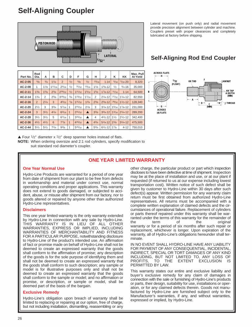
Rod Max. PullPart No. Dia. A B C D F G H J K KK At Yield
AC-2-05 5/8 3/4 11/4 2 1/2 5/8 1/2 13/16 1-14 5/16 7/16-20 8,320
AC-2-08 1 11/8 111/16 25/16 1/2 31/32 13/16 11/8 13/8-12 1/2 3/4-16 35,000
AC-2-11 13/8 15/8 23/8 229/32 1/2 111/32 15/32 15/8 17/8-12 11/16 1-14 64,500
AC-2-14 13/4 2 25/8 319/32 3/4 123/32 17/16 2 21/4-12 27/32 11/4-12 82,550
AC-2-16 2 21/4 3 45/32 7/8 131/32 13/4 23/8 25/8-12 29/32 11/2-12 128,340
AC-2-20 21/2 3 33/4 57/16 1 215/32 21/8 3 31/4-12 15/16 17/8-12 231,000
AC-2-24 3 31/2 41/4 63/16 1 231/32 ▲ 33/8 33/4-12 13/16 21/4-12 289,200
AC-2-28 31/2 31/2 5 67/16 1 315/32 ▲ 4 41/2-12 11/2 21/2-12 342,400
AC-2-36 41/2 41/2 6 77/8 1 415/32 ▲ 43/4 51/4-12 15/8 31/4-12 475,500
AC-2-44 51/2 51/2 71/4 93/8 1 515/32 ▲ 53/4 61/2-12 17/8 4-12 750,010
One Year Normal UseHydro-Line Products are warranted for a period of one yearfrom date of shipment from our plant to be free from defectsin workmanship and material under correct use, normaloperating conditions and proper applications. This warrantydoes not extend to goods damaged, or subjected to acci-dent, abuse, or misuse after shipment from our factory, nor togoods altered or repaired by anyone other than authorizedHydro-Line representatives.
DisclaimersThis one year limited warranty is the only warranty extendedby Hydro-Line in connection with any sale by Hydro-Line.THIS WARRANTY IS IN LIEU OF ALL OTHER WARRANTIES, EXPRESS OR IMPLIED, INCLUDINGWARRANTIES OF MERCHANTABILITY AND FITNESSFOR A PARTICULAR PURPOSE, notwithstanding disclosureto Hydro-Line of the product’s intended use. An affirmationof fact or promise made on behalf of Hydro-Line shall not bedeemed to create an expressed warranty that the goodsshall conform to the affirmation of promise; any descriptionof the goods is for the sole purpose of identifying them andshall not be deemed to create an expressed warranty thatthe goods shall conform to such description; any sample ormodel is for illustrative purposes only and shall not bedeemed to create an expressed warranty that the goodsshall conform to the sample or model; and no affirmation orpromise, or description, or sample or model, shall bedeemed part of the basis of the bargain.
Exclusive RemedyHydro-Line’s obligation upon breach of warranty shall belimited to replacing or repairing at our option, free of charge,but not including installation, dismantling, reassembling or any
other charge, the particular product or part which inspectiondiscloses to have been defective at time of shipment. Inspectionmay be at the place of installation and use, or at our plant ifrequested (if returned to us at our expense including lowesttransportation cost). Written notice of such defect shall begiven by customer to Hydro-Line within 30 days after suchdefect(s) appear. Written permission for any warranty claimreturn must be first obtained from authorized Hydro-Linerepresentatives. All returns must be accompanied with acomplete written explanation of claimed defects and the cir-cumstances of operational failure. Replacement of cylindersor parts thereof repaired under this warranty shall be war-ranted under the terms of this warranty for the remainder ofthe term of the original warranty or for a period of six months after such repair orreplacement, whichever is longer. Upon expiration of thewarranty, all of Hydro-Line’s obligations hereunder shall ter-minate.
IN NO EVENT SHALL HYDRO-LINE HAVE ANY LIABILITYFOR PAYMENT OF ANY CONSEQUENTIAL, INCIDENTAL,INDIRECT, SPECIAL OR TORT DAMAGES OF ANY KINDINCLUDING, BUT NOT LIMITED TO, ANY LOSS OFPROFITS, TO THE EXTENT EXCLUSION IS PERMITTED BY LAW.
This warranty states our entire and exclusive liability andbuyer’s exclusive remedy for any claim of damages in connection with the sale or furnishing of Hydro-Line’s productsor parts, their design, suitability for use, installations or oper-ation, or for any claimed defects therein. Goods not manu-factured by Hydro-Line are furnished subject only to theManufacturer’s warranties, if any, and without warranties,expressed or implied, by Hydro-Line.
ONE YEAR LIMITED WARRANTY
Self-Aligning Coupler
▲ Four 1/2” diameter x 1/2” deep spanner holes instead of flats.NOTE: When ordering oversize and 2:1 rod cylinders, specify modification to
suit standard rod diameter’s coupler.
Lateral movement (on push only) and radial movement provide precision alignment between cylinder and machine.Couplers preset with proper clearances and completelylubricated at factory before shipping.
26
1/32"LATERAL
PISTON ROD
ACROSS FLATSH
B
GACROSS(4) FLATS
JAM NUT
KK TAPA DEPTH
(MIN)
1/32(FLOAT)
C(MIN)
A
KK THDF
J THREADKD
Self-Aligning Rod End Coupler

Rod Weld Soc. BoltDia. Plate Hd. Cap Torq.MM AF B C D E F G H K C-272- L N P Screws Ft. lb. S T U X.625 .38 .44 .41 1.50 .218 4 1.12 45˚ .44 C-272-05 .50 2.00 .25 #10-24x.88 5 .398 – – –
1.000 .69 .62 .75 2.00 .281 6 1.50 30˚ .38 C-272-08 .50 2.50 .25 1/4”-20x1.0 14 .375 .750 .650 –
1.375 .88 .69 .94 2.50 .343 6 2.00 30˚ .56 C-272-11 .62 3.00 .25 5/16”-18x1.25 30 .500 1.000 .866 –
1.750 1.12 .88 1.18 3.00 .406 8 2.38 22˚ 30’ .62 C-272-14 .75 3.50 .25 3/8”-16x1.5 52 .454 1.097 – –
2.000 1.38 1.25 1.44 3.50 .406 12 2.69 15˚ .75 C-272-16 .88 4.00 .38 3/8”-16x2.0 52 .348 .950 1.298 –
2.500 1.75 1.38 1.88 4.25 .531 8 3.44 30˚ 30’ .88 C-272-20 1.00 5.00 .38 1/2”-13x2.25 128 .658 1.588 – –
3.000 2.25 1.88 2.38 5.00 .531 12 4.00 15˚ .88 C-272-24 1.00 5.50 .38 1/2”-13x2.75 128 .518 1.414 1.932 –
3.500 2.50 2.00 2.62 5.88 .656 12 4.69 15˚ 1.00 C-272-28 1.12 6.50 .38 5/8”-11x3.0 255 .607 1.657 2.264 –
4.000 3.00 2.00 3.12 6.38 .656 12 5.18 15˚ 1.00 C-272-32 1.12 7.00 .38 5/8”-11x3.0 255 .671 1.834 2.505 –
4.500 3.50 2.38 3.62 6.88 .781 8 5.69 22˚ 30’ 1.12 C-272-36 1.25 7.50 .38 3/4”-10x3.5 450 1.088 2.627 – –
5.000 3.88 2.50 4.00 7.38 .656 12 6.18 15˚ 1.25 C-272-40 1.38 8.00 .38 5/8”-11x3.75 255 .801 2.188 2.988 –
5.500 4.38 3.12 4.50 8.25 .781 12 6.88 15˚ 1.38 C-272-44 1.50 9.00 .38 3/4”-10x4.5 450 .890 2.431 3.320 –
7.000 5.75 4.00 5.94 10.38 1.031 12 8.75 15˚ 1.50 C-272-56 1.75 11.00 .50 1”-8x5.5 1090 1.132 3.094 4.226 –
8.000 6.50 4.00 6.69 11.38 1.031 16 9.75 11˚ 15’ 1.50 C-272-64 2.00 12.00 .50 1”-8x5.5 1090 .951 2.708 4.053 4.781
9.000 7.25 4.00 7.50 13.12 1.281 12 11.12 15˚ 2.00 C-272-72 2.25 14.00 .50 11/4”-7x6 2180 1.440 3.933 5.373 –
10.000 8.00 4.50 8.25 14.12 1.281 16 12.12 11˚ 15’ 2.00 C-272-80 2.50 15.00 .50 11/4”-7x6.5 2180 1.183 3.368 5.040 5.946
CouplingC-271-
C-271-05C-271-08C-271-11C-271-14C-271-16C-271-20C-271-24C-271-28C-271-32C-271-36C-271-40C-271-44C-271-56C-271-64C-271-72C-271-80
WELD-PLATE
LOCATORPIN
MACHINEMEMBER
QUICKCONNECT-DISCONNECTCOUPLING
Rod End Coupling
27
Used with the Hydro-Line style 10Rod End, the Hydro-Line Rod EndCoupling provides for close lateralalignment between the rod end andmachine member.
The two-piece steel coupling features high tensile strengthsocket head cap screws (with safety factor designed totake full load), permits quick assembly/disassembly for fastand easy installation and servicing.
To order C-271-__ and C-272-__ as an assembly, use part no. C-275-__
SMM
D
N
CAF
A A
B
L
MOUNT -05
SHE DIA.
F NO. BOLTS
G DIA.B.C.
U
MOUNT -08, -11
S
THE DIA.
F NO. BOLTS
G DIA B.C.
T
S
MOUNT -14, -20, -36
S
THE DIA.
F NO. BOLTS
G DIA.B.C.
S
S
H
G DIA.B.C.
S
G DIA. B.C.MOUNT-16, -24, -28, -32,-40, -44, -56, -72
TU T
U
E DIA.F NO.BOLTS
TUX
STUX E DIA.F NO. BOLTS
MOUNT -64, -80
Typical section AAdepending on rod diameter
H
C-272-Weld PlateP DIA.
Locator Pin
C-271-Coupling
K

Bore
11/2
2
21/2
31/4
4
5
6
7
8
10
12
14
16
18
VB
1/2
3/8
3/8
1/2
3/8
3/8
1/4
3/8
3/8
3/8
3/8
1/4
1/4
1/4
1/4
1/4
1/4
1/4
1/4
1/4
1/4
1/4
–
–
–
–
–
–
–
–
–
–
–
Oversize Rod InformationThe dimensions listed on these two pages are those that change when oversize r
MM
▲1
▲13/8
▲13/8
▲13/4
13/4
▲2
▲2
▲21/2
21/2
3
▲31/2
3
31/2
▲4
31/2
4
▲41/2
▲5
4
41/2
5
▲51/2
5
51/2
7
7
8
8
9
10
9
10
10
KK
3/4-16
1-14
1-14
11/4-12
11/4-12
11/2-12
11/2-12
17/8-12
17/8-12
21/4-12
21/2-12
21/4-12
21/2-12
3-12
21/2-12
3-12
31/4-12
31/2-12
3-12
31/4-12
31/2-12
4-12
31/2-12
4-12
5-12
5-12
53/4-12
53/4-12
61/2-12
71/4-12
61/2-12
71/4-12
71/4-12
CC
7/8-14
11/4-12
11/4-12
11/2-12
11/2-12
13/4-12
13/4-12
21/4-12
21/4-12
23/4-12
31/4-12
23/4-12
31/4-12
33/4-12
31/4-12
33/4-12
41/4-12
43/4-12
33/4-12
41/4-12
43/4-12
51/4-12
43/4-12
51/4-12
61/2-12
61/2-12
71/2-12
71/2-12
81/2-12
91/2-12
81/2-12
91/2-12
91/2-12
FT
1-14
13/8-12
13/8-12
13/4-12
13/4-12
2-12
2-12
21/2-12
21/2-12
3-12
31/2-12
3-12
31/2-12
4-12
31/2-12
4-12
41/2-12
5-12
4-12
41/2-12
5-12
51/2-12
5-12
51/2-12
7-12
7-12
8-12
8-12
9-12
10-12
9-12
10-12
10-12
A
11/8
15/8
15/8
2
2
21/4
21/4
3
3
31/2
31/2
31/2
31/2
4
31/2
4
41/2
5
4
41/2
5
51/2
5
51/2
7
7
8
8
9
10
9
10
10
AC
11/2
13/4
13/4
2
2
25/8
25/8
31/4
31/4
35/8
43/8
33/4
43/8
41/2
43/8
41/2
51/4
53/8
41/2
51/4
53/8
61/4
53/8
61/4
61/2
61/2
61/2
61/2
63/4
71/4
63/4
71/4
71/4
AD
15/16
11/16
11/16
15/16
15/16
111/16
111/16
115/16
115/16
27/16
211/16
27/16
211/16
211/16
211/16
211/16
33/16
33/16
211/16
33/16
33/16
315/16
33/16
315/16
41/16
41/16
41/16
41/16
41/8
45/8
41/8
45/8
45/8
AE
3/8
3/8
3/8
1/2
1/2
5/8
5/8
3/4
3/4
7/8
1
7/8
1
1
1
1
11/2
11/2
1
11/2
11/2
17/8
11/2
17/8
2
2
2
2
2
23/8
2
23/8
23/8
AF
11/16
7/8
7/8
11/8
11/8
13/8
13/8
13/4
13/4
21/4
21/2
21/4
21/2
3
21/2
3
31/2
37/8
3
31/2
37/8
43/8
37/8
43/8
53/4
53/4
61/2
61/2
71/4
8
71/4
8
8
11/2
2
2
23/8
23/8
25/8
25/8
31/8
31/8
33/4
41/4
33/4
41/4
43/4
41/4
43/4
51/4
53/4
43/4
51/4
53/4
61/4
53/4
61/4
8
8
9
9
10
11
10
11
11
C
1/2
5/8
5/8
3/4
3/4
7/8
7/8
1
1
1
1
1
1
1
1
1
1
1
1
1
1
1
–
–
–
–
–
–
–
–
–
–
–
D
7/8
11/8
11/8
11/2
11/2
13/4
13/4
21/8
21/8
25/8
3
25/8
3
❑
3
❑
❑
❑
❑
❑
❑
❑
❑
❑
❑
❑
❑
❑
❑
❑
❑
❑
❑
F‡
–
–
–
–
–
–
19/32
19/32
19/32
23/32
23/32
23/32
23/32
7/8
23/32
7/8
7/8
7/8
7/8
7/8
7/8
7/8
11/8
13/8
15/8
15/8
17/8
17/8
23/16
211/16
23/16
211/16
211/16
W
1
1
1
11/4
11/8
11/4
11/8
13/8
13/8
13/8
13/8
11/4
11/4
11/4
11/4
11/4
11/4
11/4
11/4
11/4
11/4
11/4
–
–
–
–
–
–
–
–
–
–
–
WF
13/8
15/8
15/8
17/8
17/8
2
2
21/4
21/4
21/4
21/4
21/4
21/4
21/4
21/4
21/4
21/4
21/4
21/4
21/4
21/4
21/4
33/16
33/16
31/2
31/2
4
4
41/4
41/2
41/4
41/2
41/2
Y•
215/32
223/32
223/32
231/32
231/32
33/32
33/32
311/32
311/32
311/32
311/32
319/32
319/32
319/32
315/16
315/16
315/16
315/16
41/16
41/16
41/16
41/16
53/16
53/16
51/2
6
61/2
67/8
71/8
73/8
713/16
81/16
91/2
RM
■
■
■
■
■
■
4
47/16
47/16
51/4
55/8
51/4
55/8
67/16
55/8
67/16
71/8
79/16
67/16
71/8
79/16
83/8
75/8
83/8
1013/16
1013/16
123/8
123/8
131/8
145/8
131/8
145/8
145/8
TK
1/2
1/2
9/16
5/16
3/4
1/2
3/4
11/16
11/8
11/8
3/4
15/16
15/16
7/8
21/8
13/4
7/8
7/8
19/16
19/16
19/16
13/8
–
–
–
–
–
–
–
–
–
–
–
XC*
63/4
71/2
75/8
77/8
87/8
9
97/8
101/8
103/4
103/4
103/4
121/8
121/8
121/8
133/4
133/4
133/4
133/4
15
15
15
15
195/16
195/16
193/4
221/2
23
253/8
255/8
257/8
293/8
295/8
331/4
XD*
71/8
81/8
81/4
81/2
95/8
93/4
103/4
11
115/8
115/8
115/8
131/8
131/8
131/8
143/4
143/4
143/4
143/4
16
16
16
16
–
–
–
–
–
–
–
–
–
–
–
XE*
67/8
73/16
75/16
79/16
81/2
85/8
87/8
91/8
10
10
10
115/16
115/16
115/16
129/16
129/16
129/16
129/16
133/4
133/4
133/4
133/4
–
–
–
–
–
–
–
–
–
–
–
XG
21/4
21/2
21/2
23/4
27/8
3
3
31/4
31/4
31/4
31/4
33/8
33/8
33/8
35/8
35/8
35/8
35/8
33/4
33/4
33/4
33/4
5
5
55/16
511/16
63/16
67/16
611/16
615/16
73/16
77/16
715/16
X
5
5
5
5
6
6
6
7
7
7
7
8
8
8
9
9
9
9
1
1
1
1
1
1
13
15
16
17
17
17
19
19
22
Dimensions shown in red are mounting dimensions.▲ Mount B not available with standard dimensions in these sizes. Contact Hydro-Line for special dimensions.‡ If no dimension is given, use FH dimension in place of F dimension and VB dimension in place of V dimen-sion.❏ Four 1/2” diameter spanner holes used instead of wrench flats on 4” diameter and larger.NOTE: Consult Hydro-Line for 20”, 24” and 30” bore dimensions.
* Add stroke to all starred dimensions.■ Refer to lower half of page 21.
** Plus 2 x stroke.• Port dimensions for standard ports only. Consult Hydro-Line for flange, manifold and special ports.
V‡
–
–
–
–
–
–
17/32
21/32
21/32
17/32
17/32
17/32
17/32
3/8
17/32
3/8
3/8
3/8
3/8
3/8
3/8
3/8
11/16
13/16
7/8
7/8
11/8
11/8
11/16
13/16
11/16
13/16
13/16
XI
28
B -.001-.003
NPTF SAE
Cus
tom
er t
o sp
ecify

XX*
71/2
81/16
83/16
87/16
91/2
95/8
10
101/4
111/8
111/8
111/8
125/16
125/16
125/16
139/16
139/16
139/16
139/16
143/4
143/4
143/4
143/4
–
–
–
–
–
–
–
–
–
–
–
rods are used.
* Male Rod End Style No. 2 is standard and will be furnishedunless otherwise specified.
** Rod End Style No. 4 will be furnished when female thread isrequired unless otherwise specified.
*** Rod End Styles No. 1, 1X, 2 and 2X are furnished studded on5/8”, 1” and 13/8” diameter rods. Larger sizes are of one-piececonstruction.
**** All Hydro-Line mounting accessories are designed to fit No. 2and 2X rod end styles only.
NOTE: A 1/8” long taper begins 1/16” from pilot face and leads to theturned down diameter, except on Rod Styles No. 5 and 6.
NOTE: Consult distributor for rod end configurations other than thoseshown.
Rod End StylesChoose from eight
22X
1
1X
5
6
10
STD.** * ** * * *
* * *
* * *
* * *
ROD ENDSTYLE NO. DIMENSIONS
29
4 STD.
* *
XJ*
51/4
51/2
55/8
57/8
61/2
65/8
67/8
71/8
75/8
75/8
75/8
83/8
83/8
83/8
93/8
93/8
93/8
93/8
01/4
01/4
01/4
01/4
31/2
31/2
313/16
513/16
65/16
73/16
77/16
711/16
97/16
911/16
23/16
XS
13/4
21/8
25/16
29/16
29/16
211/16
27/8
31/8
31/8
31/8
31/8
33/8
33/8
33/8
35/8
35/8
35/8
35/8
35/8
35/8
35/8
35/8
413/16
413/16
51/8
51/2
6
61/4
61/2
63/4
7
71/4
73/4
XT
23/8
25/8
25/8
27/8
3
31/8
31/8
33/8
33/8
33/8
33/8
31/2
31/2
31/2
313/16
313/16
313/16
313/16
315/16
315/16
315/16
315/16
–
–
–
–
–
–
–
–
–
–
–
ZB*
63/8
611/16
613/16
71/16
715/16
81/16
85/16
89/16
95/16
95/16
95/16
109/16
109/16
109/16
113/4
113/4
113/4
113/4
127/8
127/8
127/8
127/8
17
17
175/16
20
201/2
217/16
217/8
2115/16
243/8
245/8
275/8
ZE*
71/4
711/16
713/16
81/16
91/8
91/4
91/2
93/4
103/4
103/4
103/4
123/16
123/16
123/16
139/16
139/16
139/16
139/16
147/8
147/8
147/8
147/8
–
–
–
–
–
–
–
–
–
–
–
ZF*
63/8
67/8
7
71/4
81/8
81/4
85/8
87/8
93/8
93/8
93/8
105/8
105/8
105/8
113/4
113/4
113/4
113/4
123/4
123/4
123/4
123/4
17
17
175/16
1915/16
207/16
217/8
221/8
223/8
251/8
253/8
285/8
ZJ*
6
61/4
63/8
65/8
73/8
71/2
73/4
8
81/2
81/2
81/2
95/8
95/8
95/8
103/4
103/4
103/4
103/4
113/4
113/4
113/4
113/4
155/16
155/16
155/8
18
181/2
195/8
197/8
201/8
223/8
225/8
255/8
ZL*
65/8
71/8
71/4
71/2
83/8
81/2
819/32
827/32
911/32
915/32
915/32
1011/32
1011/32
101/2
1115/32
115/8
115/8
115/8
125/8
125/8
125/8
125/8
–
–
–
–
–
–
–
–
–
–
–
ZM**
75/8
81/8
81/4
83/4
91/2
93/4
10
101/2
11
11
11
117/8
117/8
117/8
13
13
13
13
14
14
14
14
–
–
–
–
–
–
–
–
–
–
–
ZT*
73/8
81/16
83/16
87/16
911/16
913/16
101/16
105/16
1111/16
1111/16
1111/16
131/4
131/4
131/4
147/8
147/8
147/8
147/8
161/4
161/4
161/4
161/4
–
–
–
–
–
–
–
–
–
–
–

REV. 11/98 10,000 CG
Delivering Engineered Solutionsin Actuation Worldwide
HYDRO-LINE Actuation Products
HM SERIES CYLINDERS• Conform to international metric
specifications ISO 6020/2 andDIN 24 554
• 25 mm to 200 mm bore sizes• 210 BAR nominal hydraulic• All steel construction
ROCKFORD SERIESCYLINDERS• ASAE interchangeable
agricultural cylinders• Rockford 2500 –2500 psi hydraulic• Rockford 3000 –3000 psi hydraulic
ELECTRONIC FEEDBACKCYLINDERSHydraulic or pneumatic cylinderswhich incorporate cylinder positionsensing and feedback throughoutthe stroke. Available in N5, R5,A5, Q5, HM, HW, SM or specialcylinders.
SERIES 20/30 BOOSTERS• Standard series to 5000 psi output• Custom designs to 20,000 psi T SERIES AIR/OIL TANKS• All steel constructionQT SERIES AIR/OIL TANKS• Aluminum end caps and translucent
tubing
N5 SERIES CYLINDERS• NFPA interchangeable• N5 – 3000 psi nominal hydraulic• AN5 – to 250 psi very heavy-
duty pneumatic• LAN5 – to 250 psi very heavy-
duty pneumatic – permanentlylubricated
• All steel construction
R5 SERIES CYLINDERS• NFPA interchangeable • A5/R5 – to 250 psi pneumatic• LA5/LR5 – to 250 psi pneumatic –
permanently lubricated• HA5 – to 400 psi hydraulic• HR5 – 1500 psi nominal hydraulic
Q5 SERIES CYLINDERS• NFPA interchangeable • Q5 – to 250 psi pneumatic• LQ5 – to 250 psi pneumatic –
permanently lubricated• HQ5 – to 400 psi hydraulic• Aluminum construction
CUSTOM CYLINDERSCustom cylinders to meet specialrequirements• Bores to 48˝• Strokes to 300˝• Pressures to 10,000 psi or higher
V5 SERIES CYLINDERS• NFPA Interchangeable• To 200 psi pneumatic• Aluminum construction• Now available in
5”, 6” and 8” bore
HW SERIES CYLINDERS• Welded construction• 3000 psi nominal hydraulic
TSAVER CYLINDERS• Threaded body construction• To 200 psi pneumatic• To 1000 psi nominal hydraulic
SM SERIES CYLINDERS• Steel mill type construction• MSM–2000 psi nominal hydraulic• HSM–3000 psi nominal hydraulic• ASM–Pneumatic
830 MEREDITH WAYSPARKS, NEVADA 89431 U.S.A.702-355-7071 • FAX 702-355-7170
HIGHWAY 20 WEST • P.O. BOX 2068DECATUR, ALABAMA 35602 U.S.A.205-350-2603 • FAX 205-351-1264
HYDRO-LINE s.r.1.VIA CAPRETTI 12/141-25136 STOCCHETTA BS, ITALY(39)-030-201-6211 • (39)-030-209-1500
HEADQUARTERS4950 MARLIN DRIVE • P.O. BOX 2045
ROCKFORD, ILLINOIS 61130 U.S.A.815-654-9050 • FAX 815-654-3393
4908 HOVIS ROADCHARLOTTE, NORTH CAROLINA 28208 U.S.A.
704-394-0043 • FAX 704-394-0073
PATRICK GREGORY ROADWOLVERHAMPTON WEST MIDLANDS, WV11 3DZ U.K.
(0) 1902 304000 • FAX (0) 1902 305676
VISIT OUR WEB SITE:www.hydro-line.com