N4PY Icom Control Program Version 3 Icom Control Program Version 3.28 ... There is also the ability...
74
N4PY Icom Control Program Version 3.29 Personal Computer This program is a 32 bit windows program. Your personal computer is an integral part of the your transceiver. The minimum system requirements for your PC to operate your radio is a Windows XP system. Connect one end of the serial cable to the serial port connection of the radio and connect the other end of the serial cable to the 9 pin serial port connector on your PC. If your computer does not have a serial port, almost any USB to serial converter will work fine. This program will work on the following Windows versions: All versions of Windows XP (both 32 and 64 bit) All versions of Windows Vista (both 32 and 64 bit) All versions of Windows 7 (both 32 and 64 bit) All versions of Windows 8 and 8.1 (both 32 and 64 bit) All versions of Windows 10 (both 32 and 64 bit) Screen resolution of at least 1024 X 768 is recommended. Also, in order for this program to pick up frequency, mode, and filter changes performed directly on the radio, "CIV Transceive" must to turned on in the radio. The parameter "CIV with IC-735" must be turned off for this program to work properly. PC to Icom radio Serial Connection Connect a 9 pin serial port cable between the Icom radio serial interface and an available COM port on your PC. When you start the Icom radio control program for the first time you need to tell the program which COM port the radio will be using and what Icom radio you are using. Choose the appropriate COM port, speed, and radio under the INTERFACE section of the SETTINGS panel. It is also possible to use a USB to SERIAL PORT adapter to operate the radio over a USB port. Please refer to the adapter documentation for information on using a USB port as a Serial Port. Some USB adapters do not work very well and others work great. If you are using a CT-17 and change radios, it is necessary to "reboot" the CT-17 much in the same way you reboot your computer. Unplug the 9-15V DC power source for 10 seconds, then reconnect. This is necessary for proper CT-17 operation. If you do not have a CT-17 or any other CIV level converter, you have two other choices: 1. Buy a 3rd party converter for $25 to $100: http://k1nu.home.comcast.net/k1nu/Products/ http://www.cssincorp.com/prod-cable.htm http://home.att.net/~n8st/icom.html http://www.microham.com/USB%20interfaces.html http://home.comcast.net/~n4vas/wsb/html/view.cgi-home.html-.html
-
Upload
nguyenkiet -
Category
Documents
-
view
225 -
download
1
Transcript of N4PY Icom Control Program Version 3 Icom Control Program Version 3.28 ... There is also the ability...

N4PY Icom Control Program Version 3.29
Personal Computer
This program is a 32 bit windows program. Your personal computer is an integral part of the your transceiver. The minimum system requirements for your PC to operate your radio is a Windows XP system. Connect one end of the serial cable to the serial port connection of the radio and connect the other end of the serial cable to the 9 pin serial port connector on your PC. If your computer does not have a serial port, almost any USB to serial converter will work fine.
This program will work on the following Windows versions: All versions of Windows XP (both 32 and 64 bit) All versions of Windows Vista (both 32 and 64 bit) All versions of Windows 7 (both 32 and 64 bit) All versions of Windows 8 and 8.1 (both 32 and 64 bit) All versions of Windows 10 (both 32 and 64 bit)
Screen resolution of at least 1024 X 768 is recommended.
Also, in order for this program to pick up frequency, mode, and filter changes performed directly on the radio, "CIV Transceive" must to turned on in the radio. The parameter "CIV with IC-735" must be turned off for this program to work properly.
PC to Icom radio Serial Connection
Connect a 9 pin serial port cable between the Icom radio serial interface and an available COM port on your PC. When you start the Icom radio control program for the first time you need to tell the program which COM port the radio will be using and what Icom radio you are using. Choose the appropriate COM port, speed, and radio under the INTERFACE section of the SETTINGS panel.
It is also possible to use a USB to SERIAL PORT adapter to operate the radio over a USB port. Please refer to the adapter documentation for information on using a USB port as a Serial Port. Some USB adapters do not work very well and others work great.
If you are using a CT-17 and change radios, it is necessary to "reboot" the CT-17 much in the same way you reboot your computer. Unplug the 9-15V DC power source for 10 seconds, then reconnect. This is necessary for proper CT-17 operation.
If you do not have a CT-17 or any other CIV level converter, you have two other choices:
1. Buy a 3rd party converter for $25 to $100:
http://k1nu.home.comcast.net/k1nu/Products/
http://www.cssincorp.com/prod-cable.htm
http://home.att.net/~n8st/icom.html
http://www.microham.com/USB%20interfaces.html
http://home.comcast.net/~n4vas/wsb/html/view.cgi-home.html-.html

http://n9zle.tripod.com/cable.htm (warning -- this is a tripod-hosted site; don't go here without a firewall!)
http://hosenose.com/detail.asp?product_id=LCU-3 (by W1GEE -- recent traffic indicates problems when used with IC765 or IC781)
You'll find reviews of the above products at http://www.eham.net/reviews/products/53
2. Build one yourself
This is a fun project you can do for less than $10 if you don't get too fancy with the packaging. Radio Shack has everything you need, as does Digikey and other mail order houses. The circuit I use was published by Nigel KG7SG in the 7/92 QST, and can be found in http://www.qsl.net/civ_commander/interface.jpg ; like many others, it derives its power from the serial port's modem control signals DTR and RTS. This is fine, as long as you configure the program to assert DTR. See the "Interface" section for how to do this. Alternatively, you can power the circuit from an external source of +12VDC. Ekki DF4OR has this and some other circuits on his site at http://www.plicht.de/ekki/civ/civ-p2.html , An excellent example of a MAX232-based design done correctly can be found in http://www.seed-solutions.com/gregordy/Amateur%20Radio/Experimentation/C IVInterface.htm .
Basic Operation
Turn on the Icom radio using the front panel switch. You must wait until the Icom radio is fully operating. The Icom radio must always be turned on first before the program is started.
Start the N4PY Icom Control program. The control program should connect to the Icom radio. If needed you may change the selected serial port, baud rate, and radio type in the INTERFACE section of the SETTINGS screen.
When using the Icom radio with this control program, do not attempt to use the controls on the Icom radio other than the main frequency knob, mode changes, or filter settings. If you use any other controls on the radio, the program will get out of step with the radio.
The program also supports the LP-100A watt meter from Telepost. See www.telepostinc.com for further details on this device.
Direct Frequency Entry
You can entry a frequency for either VFO A or VFO B directly from the computer keyboard. Mouse click on the displayed frequency. You will see a flashing cursor on the digit you clicked. Then enter the digits from the keyboard. Once you have entered the frequency completely, press the "enter" key on the keyboard to have the frequency take effect. If you make a mistake, press the "ESC" key to cancel the entry so you can start over.

Mouse Wheel
There are options for the mouse wheel to be used for Frequency Tuning, Volume Control, Pod Knob, Frequency Tuning + Slider, and Pod Knob + Slider. These option are in the "Call Sign, TopTen" settings window.
You can tune the radio frequency by hovering over a displayed VFO digit and moving the mouse wheel. This allows for instant frequency tuning at almost any tuning rate you want. The supported digits are the all the digits to the right of the first decimal point in the displayed frequency area plus the MHZ digit. This works with both VFO A and VFO B.
If "Frequency Tuning" is selected, the tuning step size for the mouse wheel is the selected tuning step size.
The option called "Pod Knob" makes the mouse wheel simulate a Tentec remote tuning pod knob. If you use a mouse with a mouse wheel that can spin, this makes an excellent tuning knob. The mouse wheel can be assigned to any of the functions for the Tentec remote pod. I am using the Logitech MX 620 mouse as a pod knob with excellent results. If the mouse wheel seems a little slow, check the setting for "Tuning Knob Desense Factor" in the "Remote Pod Fkey" settings window. Set it to at 1 if you are not using the Tentec remote tuning pod. You can also make the mouse wheel have a high speed setting. In "Preferences4", you can set the "Sensitivity" to somewhere around 10 or so. This is the number of mouse wheel pulses received in 150 milliseconds. The higher this number is, the faster you have to spin the mouse wheel to go into high speed mode. The "High Speed Tuning Factor" is used as a multiplier for the frequency step. So once high speed is achieved, this factor says how much faster you move in frequency. I find a setting of 10 or so for each of these values works pretty well.
There are also two options that have "Slider" added to them. These options will allow any slider on the program radio panel to be moved with the mouse wheel when the mouse is over that slider. When the mouse wheel is not over a slider, either "Frequency Tuning" or "Pod Knob" will be in effect.
Remote Operation
There is now a new function called Client-Server. Read the file "CSRemote.txt" that is included in your folder where you installed the program. This describes exactly how to do remote operation. There is also the ability to control the remote radio from a local radio. This is called remote mirrored radio operation. This is fully described in "CSRemote.txt".
Control Panel Buttons
Special Right Click on Mode Button for IC-7800
All the receive mode buttons (AM, LSB, USB, CW, FM, PSK, RTTY) have a special function if "DUAL" receive is turned on. If you right click the mode button, they will send the mode, default filter, and default AGC to the VFO B receiver instead of the VFO A receiver.
DUAL

This button controls the dual receive function for radios that have dual watch or a second receiver. If this button is off, the sub receiver will always be muted. With this button on, both the main and sub receivers will be heard. Also, if this button is off, no data will be sent to the sub receiver until DUAL is turned on.
On the IC-7800, if DUAL is on, the left headphone has the main receiver audio and the right headphone has the sub-receiver audio. With DUAL off, both the left and right headphone have the main receiver audio.
Right clicking the "DUAL" button will turn on "A=B Frequency Tracking" This mode is indicated with a "DIV" displayed just above the DUAL button. With this mode on, VFO B will automatically follow VFO A in frequency. To turn off this mode, left click on the "DUAL" button. The purpose of this mode is for diversity reception from two receivers at the same time. For true diversity reception, the two receivers must have separate antennas.
Please note that if "DUAL" is off, all updates to the sub receiver will be saved and not actually sent until "DUAL" is switched on.
The IC-9100 is a special case. It has dual receive but does not have dual watch. The second receiver cannot be on the same band as the main receiver. This means DUAL will not function if VFO A and VFO B are on the same band. If VFO A and VFO B are on the same band, the program VFO A will be assigned to the main receiver VFO A and the program VFO B will be assigned to the main receiver VFO B. If VFO A and VFO B are on different bands, the program VFO A will be assigned to the main receiver VFO A, and the program VFO B will be assigned to the sub receiver VFO A.
M Sliders
This button is just for the IC-7800. It is only visible when DUAL is on. It is used to toggle the NR slider, NB slider, SQ slider, and RF slider functions between VFO A (main receiver) and VFO B (sub-receiver). When set for the main receiver, this button is labelled "M Sliders". When set for the sub-receiver, this button is labelled "S Sliders" and the 4 sliders changed by this button are then labelled in lower case to show they are now for the sub-receiver.
ManMD
This button controls whether or not filter and step information automatically change when a new mode is selected. With this button off, when a new mode is selected, a new filter and step will automatically change according to the mode. With this button on, only the mode will change when a new mode is selected.
AM
Clicking this button will put the main receiver in AM mode. Also, while in AM Mode, the filter button operation is different for the 756PROII, 756PROIII, 7200, 746PRO, 7700, and 7800. See the filter button section for more information.
LSB

Clicking this button will put the main receiver in LSB mode.
USB
Clicking this button will put the main receiver in USB mode.
CW
Left clicking this button will put the main receiver in CW mode. Right clicking this button (not available on the IC-756, IC-781, or IC-775) will put the main receiver in CWR mode. An interesting side effect of this mode is you can tell when you are tuned directly onto a CW signal by swapping back and forth between CW and CWR mode. If the pitch of the signal does not change, you are perfectly tuned to the signal.
The 746Pro, 756ProII, 756ProII, 7700, and 7800 have a SSB/CW sync tuning feature. This feature must be turned off in the radio menus for this program to work properly.
FM
Clicking this button will put the main receiver in FM mode. For the IC-706 only, right clicking on this will select wide band FM for things like the FM broadcast band.
PSK
Clicking this button will put the main receiver in PSK mode for the 7700 and 7800 and all put other radios in USB mode. Right clicking this button will put the 7700 and 7800 in PSK-R mode and all other radios in LSB mode.
RTTY
Clicking this button will put the main receiver in RTTY mode. Right clicking this button (not available on the IC756, IC775, or IC-781) will put the main receiver in RTTY-R mode. If your radio does not have RTTY mode, then you will get LSB for RTTY mode and USB for RTTY-R mode.
Sto SP
This button stores the frequency, mode, and filter in a temporary memory for later retrieval.
Rcl SP
This button retrieves the values of frequency, mode, and filter, last saved with the "Sto SP" button.
STORE
STORE opens the Store Memory window and prompts you for station data. You can also add a PBT value to the saved memory. If you

edit the memory window, you can add "PBT=" text to specify a PBT value to be set when the memory is recalled. For example, if you want a PBT value of 1000 hertz, anywhere in the "Notes" box add the following text:
PBT=1000
For a minus 1000 hertz PBT add the following:
PBT=-1000
Make sure not to have any spaces on either side of the "=".
There is also a setting to turn the speech processor on and off from a memory. If you put "SP=1" in the notes section of a memory, the speech processor will be turned on when you recall the memory. If you put "SP=0" in the notes section, the speech processor will be turned off when you recall the memory.
For most newer Icom radios, the setting for FM CTCSS, is also saved. This setting is saved in the first line of the notes section of the memory. The saving of this setting is controlled by the option in "Preferences4" called "Save FM CTCSS in Mem".
RECALL
RECALL brings up the Recall Memory window and allows you to select stations.
Scan
Clicking the "Scan" key will cause the stored memory file to be scanned one frequency at a time, beginning at the current entry. The time spent on each memory is called the dwell time. The dwell time is specified in the preferences window. It must be between 1 and 99 seconds. The default dwell time is 2 seconds. All the memories in the loaded memory file will be scanned. When it gets to the last entry, it will start over at the first memory of the file. You will most likely make special memory files to use this scan feature. You can stop the memory scan by clicking again on the "Scan" button. If you add the word "skip" in lower case anywhere in the "notes" section of a memory, the memory will be skipped during the scan function.
The memory scan will be stopped if you transmit while the scan is in progress. You can configure an automatic resume time. See the "Preferences4" section.
VFO A
Left clicking this button will cause the main VFO A frequency to go down by one step amount. Right clicking this button will cause the main VFO A frequency to go up one step amount.
VFO B

Left clicking this button will cause the alternate VFO B frequency to go down by one step amount. Right clicking this button will cause the alternate VFO B frequency to go up one step amount.
FAST A
Left clicking this button will cause the main VFO A frequency to go down by one step amount times the "Fast Tuning Mult". Right clicking this button will cause the main VFO A frequency to go up by one step amount times the "Fast Tuning Mult" amount. See "Fast Tuning Mult" in "Preferences2" below.
FAST B
Left clicking this button will cause the alternate VFO B frequency to go down by one step amount times the "Fast Tuning Mult". Right clicking this button will cause the alternate VFO B frequency to go up by one step amount times the "Fast Tuning Mult" amount. See "Fast Tuning Mult" in "Preferences2" below.
FILTER A
Left clicking this button will cause the main VFO A filter to go to the next wider filter. Right clicking this button will cause the main VFO A filter to go to the next narrower filter.
FILTER B
Left clicking this button will cause the alternate VFO B filter to go to the next wider filter. Right clicking this button will cause the alternate VFO B filter to go to the next narrower filter. The VFO B filter setting in displayed in the black area just to the right of the S meter. Here, there are three green indicators to show VFO B mode at the top, then VFO B filter just below mode, and finally VFO B step just below filter.
LO CUT
Left clicking this button will cause the next lower locut passband step to be selected. Right clicking this button has exactly the opposite effect. This button is useful when QRM appears on the low side of the passband. It allows the low side of the passband to be tuned while keeping the high side of the passband constant. The numeric button directly below the LO CUT button indicates how many steps the low cutoff frequency has moved. You can reset the low cutoff to zero by left clicking this numeric key.
HI CUT
Left clicking this button will cause the next lower hicut passband step to be selected. Right clicking this button has exactly the opposite effect. This button is useful when QRM appears on the high side of the passband. It allows the high side of the passband to be tuned while keeping the

low side of the passband constant. The numeric button directly below the HI CUT button indicates how many steps the high cutoff frequency has moved. You can reset the high cutoff to zero by left clicking this numeric key.
PBT
Clicking this button on enables pass band tuning for the VFO A receiver. Dragging the scale to the right of the button controls the amount of PBT used. You can right click on the PBT scale to zero it. This control actually moves LO CUT and HI CUT together. LO CUT, HI CUT, and PBT are all closely related. The ranghe of PBT is + or - 1280. The 1280 scale is a relative value that is related to the filter selected for how much movement. This value is 10 times the step value for LO CUT or HI CUT.
RIT
Clicking this button on enables RIT for the VFO A receiver. Dragging the scale to the right of the button controls the amount of RIT used. You can right click on the RIT scale to zero it. Because Icom receivers do not have computer commands for RIT, this control actuall uses SPLIT and VFO B to operate. RIT can only be used when SPLIT is off and DUAL is off.
XIT
Clicking this button on enables XIT for the VFO A receiver. Dragging the scale to the right of the button controls the amount of XIT used. You can right click on the XIT scale to zero it. The XIT shares the same drag window as RIT. Because Icom receivers do not have computer commands for XIT, this control actually uses SPLIT and VFO B to operate. XIT can only be used when SPLIT is off and DUAL is off.
A / B
Clicking this button causes the VFO A and VFO B contents to be swapped. This includes frequency, mode, filter, AGC, LOCK status, and antenna setting.
A = B
Clicking this button causes the contents of VFO A to be copied into VFO B. This includes frequency, mode, filter, and AGC setting.
XFC
Clicking this button causes the VFO A and VFO B contents to be swapped if SPLIT is on. This allows the transmit frequency to be checked for activity.
SPLIT
Clicking this button causes the transmit frequency to shift from the VFO A frequency to the VFO B frequency.

The IC-9100 is a special case. The second receiver cannot be on the same band as the main receiver. If VFO A and VFO B are on the same band, the program VFO A will be assigned to the main receiver VFO A and the program VFO B will be assigned to the main receiver VFO B. If VFO A and VFO B are on different bands, the program VFO A will be assigned to the main receiver VFO A, and the program VFO B will be assigned to the sub receiver VFO A.
LOCK
Clicking this button causes VFO A to be locked so that it does not change in frequency.
FAST, MED, SLOW
These buttons set the AGC speed. They are not available on the IC-756 IC-775, or IC-781. For the IC-7800, if "DUAL" is turned on, you can right click to set the AGC rate for the sub-receiver. Additionally, the IC-7800 and IC-7700 have a "Man" button for manual AGC using AGCVR and the "AG" slider.
Re-Initialize Button
This button is there is overcome an Icom shortcoming. If any pot is turned on the Icom radio while under program control, all the radio values return to there pot settings. This causes the program to get out of step with the radio. The "Re-Initialize" button causes the program to resend all its settings to the radio to get the program back in step with the radio.
S Meter Button
This button is only available on the IC-7700, IC-7800, IC-746PRO, IC-7200, IC-756PROIII, and IC-703. It allows the meter display for transmit to be toggled between S meter, power meter, SWR meter, speech compression meter, and ALC meter. In receive, the meter always shows S meter reading.
Step Buttons
These buttons set the frequency step size according to their value. They are user definable in the "Steps" window of the "settings" menu. Left clicking these buttons changes the VFO A step size. Right clicking these buttons changes the VFO B step size.
Band Buttons
These buttons are band register buttons. They return you to the last frequency and mode you were using on the appropriate band section. The column labelled "CW" is for the normal "CW" section of that band. Clicking these buttons will return you to the last frequency and mode you were using when in this section of the band. The column labelled "SSB" will return you to the last frequency and mode you were using when in this section of the band. The "SWL" column will return you to the last frequency and mode

you were using when in this band. The "GEN" band button is a general band register that gets used if the frequency is not in any other band. The band buttons save the frequency, mode, filter, and antenna setting for each band.
Also, you can access the ham band buttons with the function keys. Shift F1 to Shift F9 corresponds to the 160 to 10 meter SSB band buttons and Ctrl F1 to Ctrl F9 corresponds to the 160 to 10 meter CW band buttons.
The "60" button under SSB, is a special button. In order to handle the unique requirements of this band, this button has a special click feature. Once you are on the band, you can toggle through the 5 band channels by left clicking to go down one channel or right clicking to go up one channel. New priviledges now allow CW on the center frequency of each channel. If you set CW mode while on 60 meters, then left and right clicking the 60 meter band button will move you to each center frequency of each channel for CW.
AMTN
The AMTN (AMP TUNE) button is to make tuning an amplifier easier. When you click the "AMTN" button, several steps happen automatically. They are 1) The current mode and frequency is save in the scratch pad memory. 2) The frequency is moved up 5 kHz. 3) CW mode is set. 4) A wide filter is selected. 5) The Step rate is set to 1 kHz. 6) The griffin tuning knob is set to ALC to control power. 7) The Icom radio power level is set to the previous saved value for this band and mode.
While the "AMP TN" button is "RED", you should first make sure the frequency is clear. If it is not, tune to a clear frequency with the mouse by clicking the radio panel knob. Once a clear frequency is found, key your rig with your PTT or CW key and tune your amplifier. Use the remote tuning knob to set the Icom radio output power to correct drive level. When the AMP is tuned, click the "AMP TN" to exit this mode. The frequency, mode, and step will be restored to original values. The Icom radio power output value will be saved and used anytime "AMP TN" is again clicked. This value is kept separate by band and mode. Try this function out. It is a real time saver. The more you use it, the more you will like it.
There is also a "pulse tune" method when using Amp Tune. This feature is enabled by setting "PTT Amp Tune Pulse" check box in the "preferences3" window of the "settings" menu. When "AmTn" is on, clicking the "PTT" button will cause a pulsing action to help tune an amplifier in a 50 percent duty cycle instead of 100 percent.
TUNE
The power when the "TUNE" button is clicked is remembered. When you click "TUNE", set the power to what you want the tune power to be with the TX slider. When you click "TUNE" off, the power will be restored to the previous value. The next time you click "TUNE", it will remember the tune power value and set it to this value. Try it, it may save your finals! This option may be

overridden with the "No Tune Save" option described in the "Preferences3" section.
ID
The ID button is used to activate a 10 minute ID timer to assist in meeting the 10 minute FCC ID requirement. Clicking this button causes it to turn blue and send out the ID when the PC clock minute changes to 0, 10, 20, 30, 40, or 50.
To turn the timer off, click the button again and it will go black, indicating the timer is now off.
This option must be enabled by turning on the check box in "Preferences3" called "Auto Cw ID".
If you right click the ID button, it will send out the CW ID immediately.
Transmit Disable
This key is used to enable and disable the transmitter. If the button red, the transmitter is set to 0 power output. For the 7700, 7800, 746Pro, 756ProII, and 756ProIII, it is labelled "XmtD". For all other radios, it is labelled "Xmit Disable".
DM
This button is only on the 7700, 7800, 746Pro, 756ProII, and 756ProIII. It controls going into and out of datamode. Data mode is also automatically turned on when going into PSK mode and automatically turned off when leaving PSK mode. You can disable the automatic switching of this mode by turning on the option "Manual Data Mode" located in the "Preferences3" window of the settings menu.
Call
This button brings up the call sign window. In order to use this feature, you must have the BuckMaster CDROM installed. Once you have installed the BuckMaster database on your hard drive, you can set the "HamCall Drive Letter or Path" in the "Preferences" window to "c:\ham0\" without the quotes. This will allow calls to be looked up without the BuckMaster CDROM in its drive.
Speech
This button turns the speech processor and off and on. When the speech processor is turned on, you will see the word "Sp xxx", where xxx is the level of speech processing, near the main frequency. The level of speech processing is set with a slider in the SSB settings menu. It has a range of 0 to 9 with 0 being no processing and 9 being maximum processing.
SSB Transmit Filter Bandwidth

For the 756Pro, 756ProII, 756ProIII, 746Pro, IC-7700, and IC-7800, there are transmit filter settings of wide, medium, and narrow, in the SSB settings menu.
Main Display Panel
The main display area contains information about A and B VFO's, tuning steps, AGC selection and Local/UTC time. The Larger of the frequency displays is VFO-A; VFO-B the smaller.
Mode Selection
Select the mode for the current VFO using the mode buttons. To set the transmit mode in split mode select A/B, set the mode and press A/B again. In Simplex the current VFO's mode will be both the receive and transmit mode.
PTT
The PTT button provides manual PTT control. With Manual PTT control you can place the Icom radio into transmit mode from the radio panel. This is equivalent to pushing the PTT control on a microphone connected to the front panel.
Vox
Toggle VOX operation ON and OFF. The button text will change color whenever VOX is turned ON. This button is not available on the IC-756, IC-775, or the IC-781.
Mon
The mon button allows you to hear your transmit audio. Use it when adjusting microphone or audio input levels. This function is not available on the IC-756, IC-775, or IC-781.
Mute
Used to temporarily silence the received audio.
NBlk
This button turns the noise blanker on and off. For the IC-7700 and IC-7800, see the "NB Slider" description. This button is not available on the IC-756, IC-775, or the IC-781.
NR Slider
This slider sets the noise reduction level. It is labelled "NR". For the IC-7800, if DUAL is on and the "M SLIDERS" button has been changed to "S SLIDERS", this slider is labelled "nr" and then controls the noise reduction level for the sub-receiver. The label for this slider is also a button to turn its function on and off.

NB Slider
This slider is only on the IC-7700 and IC-7800. It sets the noise blanker level. It is labelled "NB". For the 7800, if DUAL is on and the "M SLIDERS" button has been changed to "S SLIDERS", this slider is labelled "nb" and then controls the noise blanker level for the sub-receiver. The label for this slider is also a button to turn its function on and off.
DS Slider
This slider is only on the IC-7700 and IC-7800. It sets the dig-sel level. It is labelled "DS". For the 7800, if DUAL is on and the "M SLIDERS" button has been changed to "S SLIDERS", this slider is labelled "ds" and then controls the digi-selr level for the sub-receiver. The label for this slider is also a button to turn its function on and off.
AF Slider
This slider is only on the IC-7700 and IC-7800. It sets the APF (audio peak filter) frequency. It is labelled "AF". For the 7800, if DUAL is on and the "M SLIDERS" button has been changed to "S SLIDERS", this slider is labelled "af" and then controls the APF frequency for the sub-receiver.
NO Slider
This slider is on the IC-7700, IC-7800, 746PRO, 756PRO, 756PROII, and 756PROIII. It sets the manual notch frequency. It is labelled "NO". The label for this slider is also a button to turn the manual notch on and off. Additionally, for the IC-7800, if DUAL is on and the "M SLIDERS" button has been changed to "S SLIDERS", this slider is labelled "no" and then controls the manual notch frequency for the sub-receiver. If "S Sliders" is selected, this label button will turn manual notch on and off for the sub-receiver.
AG Slider
This slider is only on the IC-7700 and IC-7800. It sets the AGCVR decay rate. It is labelled "AG". For the 7800, if DUAL is on and the "M SLIDERS" button has been changed to "S SLIDERS", this slider is labelled "ag" and then controls the AGCVR decay rate for the sub-receiver.
Squelch
This slider is labelled "SQ". It controls the squelch setting of the VFO A receiver. For the IC-7800, if DUAL is on and the "M SLIDERS" button has been changed to "S SLIDERS", this slider is labelled "sq" and then controls the squelch level for the sub-receiver.
VSC

For the 7700, 7800 and 746Pro, VSC can be toggled on and off with the "SQ" label button. VSC stands for "voice activated squelch" and is only available on these radios.
Rf Gain
This slider is labelled "RF". It controls the RF gain level of the VFO A receiver. For the IC-7800, if DUAL is on and the "M SLIDERS" button has been changed to "S SLIDERS", this slider is labelled "rf" and then controls the RF gain level for the sub-receiver.
Volume VFOA
This slider is labelled "VA". It controls the volume for the main receiver.
Sub-Receiver Balance Control
This slider is labelled "BL" and is only available on the 756PRO and 756PROII. It controls the volume balance between the main and sub receiver. It is only operational when DUAL is on.
Sub-Receiver Volume Control
This slider is labelled "VB" and is available on radios that have a sub-receiver. It controls the volume of the sub receiver. It is only operational when DUAL is on.
The IC-9100 is a special case. It has dual receive but does not have dual watch. The second receiver cannot be on the same band as the main receiver. This means VB will not function if VFO A and VFO B are on the same band. In fact in this case it will actually control the main receiver volume. It will only function if VFO A and VFO B are on different bands and DUAL is turned on.
Attn
The Attn button activates the RF attenuator. This button is not available on the IC-756, IC-775, or IC-781.
PreAmp
The PreAmp button activates the preamp. This button is not available on the IC-756.
Filter Buttons
For the 706MKII, 718, 756, 703, 746, 736, and 738 there are 3 filter buttons. Select between normal filter, wide filter, and narrow filter depending on mode and optional filters installed.
For the 781 amd 775 there are 2 filter buttons. Select between normal filter, wide filter, or narrow filter depending on mode and optional filters installed.

For the 756PRO, there are 3 filter buttons. They select filter 1, 2, or 3 according to your filter definitions in the 756PRO.
For the 756PROIII, 756PROII, 746PRO, 7000, 7200, 7700, and 7800, the radio panel provides 12 buttons for quick access to the most often used filters. Each of these 12 buttons can be programmed with your choice of filters. To see the filter options right-click on any filter. Any of the 41 filter choices may be assigned to any filter button. For RTTY mode, you cannot use a filter wider than 2700 hertz. If you have the RTTY filter turned on for RTTY operation, then in RTTY mode changing the filter will have no effect. For AM mode with the 756PROII, 756PROII, 7200, 7000, and 746PRO only, the filter operation is very different. The top left filter button selects the radio's AM filter number 1, the top middle button selects the radio's AM filter number 2, and the top right button selects the radio's AM filter number 3. For the 7700 and 7800 in AM mode, all AM filters from 10 kHz to 2 kHz are selectable and programmable on any of the 12 filter buttons. When AM mode is selected on the 7700 and 7800, the 12 filter buttons change their assignments to the AM filter assignments. Additionally, for the 7700 and 7800, if the selected filter is less than 5800 hertz, the 6 kHz roofing filter is automatically selected. If the selected filter is 5800 hertz or greater, the 15 kHz filter is automatically selected.
Auto Notch
The "ANotch" button turns auto notch on and off. For the IC-7800, if DUAL is on, right clicking this button turns the auto notch on and off for the sub-receiver.
Cw Break-in
The "Bk-In" button sets the break-in type for CW mode. It toggles between "Bk-In" which is break-in off, "BSemi" which is semi-break in, and "BFull" which is full break-in. You can control the delay for semi-breakin with the "CW Brk" slider in the "CW Settings" window. This button is not available on the IC-756, IC-775, or IC-781.
APF
This button is only for the IC-7700 and IC-7800, It controls the APF width. Tha values are off, 320, 160, and 80 hertz. For the 7800, if DUAL is on, right clicking this button turns controls the APF width on the sub-receiver.
TPF
This button is only for the IC-7700 and IC-7800, It turns the TPF function on and off. For the 7800, if DUAL is on, right clicking this button turns TPF on and off for the sub-receiver.
Ant 1
This button toggles between antenna 1 and antenna 2. It's value is remembered by band. For the IC-7700 and IC-7800, this value runs from "Ant 1" to "Ant 4". If you have "Ant 4" defined in the IC-7700 and IC-7800 as the receive only antenna, then the "Ant 4" button position

cannot and should not be set from the program. Also, on the IC-7800, you can right click this button to change the antenna for the sub-receiver.
Rx Ant
This button toggles the receive only antenna on and off. Its value is remembered by band. You can right click this button to set the receive only antenna for the sub-receiver. This button is only on the IC-7700 and IC-7800.
Tuner On
This button, if available, engages the internal tuner and starts a tune cycle.
Tuner Off
This button, if available, turns the internal tuner off and bypasses the tuner.
Special right click on "Split" key
Right clicking on the "split" key is used as an automatic FM repeater split function. A repeater offset is automatically set in VFO B and "split" is turned on when you right click on the "split" key and you are in an FM repeater band and in FM mode. The split offsets are calculated according to receive frequency as follows:
29.6 to 29.7 MHz - Down 100 kHz 53 to 54 MHz - Down 1 MHz 144.9 to 147 MHz - Down 600 kHz 147 to 148 MHz - Up 600 kHz
Please note the the 746Pro DUPLEX feature must be turned off for this program to work properly.
Tuning Selections
When setting an "F" key on the remote pod is set to tuning selections, it will toggle between VFOA, VFOB, PBT, RIT, ALC, VOL, and RFG. VOL is for volume. Also, each key can be defined to expressly set one of the tuning knob functions. In addition to the functions that were already there you can directly define each function key to set the remote tuning knob to go to VFOA, VFOB, PBT, RIT, ALC, VOL, or RFG. This is done on the remote tuning pod configuration box. You can also make one of the function keys be a "PTT" key by selecting the "PTT" entry. There also is a "SPOT" entry. When this is selected, that function key will turn on the CW spotting tone when pressed and turn it off when released. There is also a "RF Gain" entry. When this is selected, the remote tuning knob will control the RF gain setting. Also, see the "Remote Pod Keyboard Definition" section.
There are sliders on the main control panel for Transmit Power (TX), and Keyer Speed (KS).
The keyer speed slider on the CW settings panel is a coarse adjustment. It has a range of 40 wpm. The KS slider on the front panel is a fine adjustment. It has a range of 15 wpm. The intended use is for you to
set the speed on the CW panel one time to set the general range you want. When you do this, you should first set the front panel in the middle and then use the CW panel setting to get the middle of the range you want. You then use the KS slider on the front panel as a fine adjustment of 15 wpm of the coarse range set from the CW panel. This allows the setting of keyer speed to not be touchy. In addition, if the keyer is enabled, the keyer speed is digitally displayed above the keyer slider on the front panel.
You can also change the keyer speed one word per minute at a time. If you left click the "KS" above the "KS" slider you will go down one word per minute. If you right click the "KS", you will go up one word per minute in keyer speed.
The upper of the two front panel offset drag control is for PBT. The tuning rate of both these drag control may be user configured. The lower of the two front panel offset drag controls is for RIT and XIT. This controls a single offset in hertz that may be applied to RIT or XIT depending on which is turned on. This is similar to the implementation of the offset function in the OMNI VI. This allows you while listening to a DX station, to tune in the station he is working with the RIT control, and then switch to XIT to actually work the DX station. Note that RIT and XIT only apply to VFO A.
Frequency Slider Bar
The Frequency Slider displays a coarse view of the band. The displayed band width of the bar will depend on the selected tuning steps and the setting of "Variable Frequency Scale" in "Preferences3".
The radio can be tuned using the Slider. Click and hold the left mouse button on the Slider Bar display and drag left or right. The frequency display will show the change and the radio will follow. Double click within the Slider Bar display to jump to a new frequency.
S Meter
There is an S meter compensation value that you can define to calibrate your S meter. See "S METER COMP" in the "Preferences4" section.
Using the Spectrum Display
The Spectrum Display or Sweep Window provides the operator with the ability to quickly scan the radio bands and produce a visual representation of station activity. Several user-selectable settings are available to control the width of the sweep, sweep center frequency and display features. This function is not available on the IC-756, IC-775, or IC-781.
Sweep Result Display
While the radio is sweeping through the selected frequency range the display will change to show each new point as it is processed. When the sweep is complete the radio will return to

normal operation and the result window will keep the last data displayed until a new sweep is performed or the program is restarted.
The sweep result window provides several types of information. The left and right hand boundaries indicate the start and stop points for the sweep. The range is determined by the range setting. The vertical scale provides a relative comparison between different signals. The higher the point the bigger the signal.
Sweep Pulse Width
This box is used to select how many pixels wide each plotted sweep pulse is. Wide pulses yield a fast sweep time but low resolution. Narrow pulses yield high resolution but slow sweep times. The first selection is called "Default Pulse Width" and lets the program decide the width. This box has no effect if "High Resolution" is checked since that size uses a fixed 1 pixel width size.
Sweep Center Frequency
The operator may choose to let the sweep center frequency be the same as the receiver tuned frequency with the TRACK_RECEIVER option or select MANUAL and enter the center frequency in the box provided. The MANUAL operation allows for the sweep of frequencies removed from where the radio is tuned. There is also an option called "Band Center". This option puts the center of the band you are currently tuned to in the center of the sweep window and automatically adjusts the width to match the band segment.
Sweep Range
The amount of spectrum covered in each sweep can be set using the Sweep Range control. The default range is 300 kHz.
Starting and Stopping a Sweep
Pressing the SWEEP button will begin the sweep acquisition of data for the sweep display. The process involves tuning the receiver to each frequency and getting a signal strength reading. The display is updated with each new point as it is gathered. To stop a sweep in progress press STOP at any time.
There is a selection for spectrum sweep called "MaxHold". When this is selected, only signals that are stronger than what is already displayed at that location will be changed. This allows the presence of strong signals that come and go to remain on the sweep screen.
There is a selection for spectrum sweep called "Integrate". When this is selected, the sweep display is integrated over several passes with the formula:
Displayed Value = Previous Value - Previous Value/4 + New Value/4
Thanks to KH7T for this formula.

There is also a "High Resolution" check box on the spectrum sweep. Selecting it causes the sweep display to show a large increase in resolution. However, the sweep speed is significantly slowed down when this is on. You can decide between speed and resolution with this setting.
When using the IC-7800, the sweep uses the sub-receiver, leaving the main receiver available for general operation. Do not transmit while sweep is running.
There is a "Wide Sweep" check box on the spectrum sweep. Selecting it causes the sweep display width to double. A program restart is required for the sweep panel to change size.
Main Window Title
The VFO A frequency is displayed on the main window title. This allows the frequency to be seen when the radio control panel window is minimized. This is very useful as it allows you to tune with the remote tuning knob and see the frequency while minimized.
Local/UTC time Display
The local time and UTC are displayed in the lower right hand corner of the black display area to the right of the frequency. There is a Local/UTC time correction in the Preferences window of the settings menu. This is the amount of time in hours to be added to local time to get UTC. There is also a check box for local time to be displayed in 24 or 12 hour format. Some common time zone values for this Local/ UTC correction are as follows:
ADT +3 AST +4 EDT +4 EST +5 CDT +5 CST +6 MDT +6 MST +7 PDT +7 PST +8
The program calculates local time by first getting GMT from the windows system time. It then subtracts the above hours to get local time. You must have your windows time zone set correctly for this to work properly.
There is also a check box that says "Automatic DST". When you turn this check box on, local time and UTC will be calculated automatically. With this setting on, the above time zone correction values are ignored by the program. For this to work properly, your Windows time zone must be defined properly. This setting has no effect if you have turned on the setting "PC Keeps time in UTC".
License Class
You can define your license class and have your transmit

privileges displayed on the frequency scale. You define your license class in the "preferences" section of the settings menu. You can also decide to have your transmitter follow your license class with a check box in this same area. When you define your license class, the background of the frequency scale will be blue for CW and digital mode only operation, green for phone operation, and burgundy for operation not allowed. If you select to have your transmitter follow your license class selection, transmit will be blocked when your transmit frequency is tuned to a non-authorized frequency for your class.
When you select your license class, the last selection is called "foreign". This selection is for foreign countries that have different operating privileges than the U.S. It allows you to define your operating privileges via an ASCII file called "foreign.dat". Each line of this file defines a band segment you are authorized to operate in. There are 3 entries in each line. The first entry should be either "cw" or "phone". If "cw" is specified, it means the band is restricted to CW or digital modes. If "phone" is specified, it means the band has no bandwidth restrictions. The second entry defines the starting frequency for the band segment in MHz. The third entry defines the band segment end in MHz. There is a limit of 29 entries for the entire "foreign.dat" file. The supplied "foreign.dat" is an example of how one would define a file for a foreign country that had privileges identical to a U.S. general class license.
There are also entries in the Icom.ini file to control the point that the band button segments for the 160, 80, 40, 20, 15, and 10 meter bands switch from CW to SSB. There is also one entry to control the switchover point between 40 SSB and the 41 meter SWL band. These entries are as follows with defaults as shown:
160 meter line=1.840 80 meter line=3.750 40 meter line=7.150 4041 meter line=7.300 20 meter line=14.150 15 meter line=21.200 10 meter line=28.300
You can change these values to the appropriate value for your countries usage in these bands.
There is also a "SSBRTTY.DAT" file that can be used to define the frequencies you want RTTY or SSB mode selected automatically when doing direct frequency entry. This file can have up to 28 lines for RTTY and 28 lines for SSB. Each line for RTTY must start with "RTTY", and each line for SSB must start with "SSB". Follow the mode name with a comma, followed by the starting frequency in mhz, followed by the ending frequency for the mode in mhz. This file can be edited with notepad or any ASCII text editor. Examining the file will show the exact format. The USA SSB and CW band limits are built into the program. This file is used to override those values.
Scratch Pad Memory Window
There is a scratch pad memory window. This window is toggled on and off using Alt-V. This window has a repeat of the Sto and Rcl buttons to manage the scratch pad memories and also shows you the frequency memory contents of each of the 3 scratch pad memories.

The Rcl 1 button first stores the frequency, mode, and filter in temporary scratch pad memory X and then retrieves the values of frequency, mode, and filter, last saved with the "Sto 1" button.
The Rcl 2 button first stores the frequency, mode, and filter in temporary scratch pad memory X and then retrieves the values of frequency, mode, and filter, last saved with the "Sto 2" button.
The Rcl 3 button first stores the frequency, mode, and filter in temporary scratch pad memory X and then retrieves the values of frequency, mode, and filter, last saved with the "Sto 3" button.
The Rcl X button retrieves the values of frequency, mode, and filter, last saved in scratch pad X when Rcl 1, Rcl 2, or Rcl 3 was clicked.
CW Keyboard Keyer
There is a CW keyboard keyer. It is turned on with the "Alt-K" key sequence. When the keyboard keyer is enabled, the letters "Cw Kb" will appear just to the left of the "SPLIT" key. Pressing "Alt-K" again will turn off the keyboard keyer. Some buttons may cause the keyboard focus to move from the main radio panel causing the keyboard keys to not send CW. When this happens, either click on the radio front panel with the mouse or do Alt-K twice to restore the keyboard focus. Using the CW Keyboard will force the Icom internal keyer to be enabled. If you accidently press the "enter" key while using the CW keyboard, it will put you into "direct frequency entry" mode. Press the "Esc" key to get back to CW keyboard mode or key in a frequency and press "enter" again.
Please note you must have the Bk-In button in the N4PY program set to "BFull" or "BSemi" for the CW keyboard to work properly.
The keyed characters will not be sent until a full word is typed. The space bar is necessary to define the end of a word. This allows words to be transmitted smoothly and also gives you an opportunity to correct a keying error before the word is transmitted. This full word feature can be turned off by un-checking the check box labelled "Transmit full words only" located in the "CW Keyboard" window.
The setting "Pop Out Window" when turned on allows the CW Keyboard window to go outside the main program window. This allows you to place it anywhere on the screen. However when this window is a pop out window, you will not be able to edit the CW memory text. In order to edit this text, you will need to first turn off the pop out selection.
The F12 key will toggle the CW Keyboard buffer between pause and transmitting. This key will allow you to type ahead while you are receiving. If the buffer is stopped, the "Cw Kb" will appear RED. If the buffer is transmitting, it will be black.
The speed and weight of the keyboard keyer are controlled with CW keyer speed and weight controls. Typing at the keyboard will cause the appropriate character to be transmitted in CW.
Special CW characters are as follows: BT is sent with the "-". SK is sent with the "$".

AR is sent with the "+". KN is sent with the "^". di-dah-di-dah for traffic handling is sent with the "*".
The above special character keys can be redefined with icom.ini parameters. To redefine these keys, with the program not running, find the following lines:
BT CHAR=(-) SK CHAR=($) AR CHAR=(+) KN CHAR=(^) AA CHAR=(*)
You can then change the key value that is in parentheses to change the key for the special character.
The "escape" key will immediately end sending and empty the CW internal keyboard buffer.
There are two CW weight controls. They are a "Dah Wght" and a "Dit Wght" control. The value of each weight setting appears as a number from 0.8 to 1.70 at the bottom of each weight slider. The length of a dah is computed as the length of a space times 3 times the dah weight setting. The length of a dit is computed as the length of a space times the dit weight setting. The length of a space is fixed at the keyer speed setting. Theoretical perfect 3 to 1 spacing occurs at a dah weight setting of 1.00 and a dit weight setting of 1.00. These weight controls are used on both the CW keyboard keyer and the internal paddle keyer.
Additionally, there is a slider marked "Btwn Char". This slider controls a weighting of the between character time. The normal between character time is multiplied by the value of this slider. The range is 0.5 to 4.0. This is used to either lengthen or shorten the time between sending characters. A value of 1.00 results is normal spacing for the selected speed. Obviously, this slider is only for the CW Keyboard Keyer and not for the paddle keyer.
There is a CW Keyboard window for showing the contents of the CW keyboard buffer. This window is visible when the CW Keyboard is turned on. It may be hidden by clicking the "X" in the upper right hand corner of the window. You can make the window visible again by doing Alt-K twice. The keyboard buffer is 500 characters long.
There are 5 memories that can be used with the keyboard keyer. The memories are loaded with the edit boxes on the "CW Keyboard" window. The memories are transmitted by pressing F1 for memory 1, F2 for memory 2, F3 for memory 3, F4 for memory 4, and F5 for memory 5. There are also 5 mouse buttons at the bottom of the radio panel labelled "M1" to "M5" to transmit the memories. There are also 5 CW Memory Tag edit boxes. These edit boxes, located in the "CW Keyboard" window, will change the labels on the M1 through M5 memory buttons. You can use these tags to help remember what is in each memory. They are limited to 3 characters.
The special character "#" followed by a number from 1 to 5 can be placed in a memory to cause the contents of the memory number to be sent in place of the "#" character. This is useful to increase the size of a memory for a longer message.
The special character " (double quote) can be placed at the beginning of a memory to send a file instead of the text in the memory. When

you start a memory with a " (double quote), you directly follow the " with the name of the file you want to send text from. The internal CW keyboard buffer is limited to 511 characters so the file cannot be larger than 511 characters. You can never be more than 511 characters ahead of what is being transmitted. The file must be built with an ascii text editor such as notepad. If you build the file with notepad, the actual name of the file will have a ".txt" added to it. The basic name itself must be 8 characters or less and not have spaces or special characyers in it. The file must be located in the c:\n4pyic folder or wherever you have the program installed.
The special character "%" followed by a number from 1 to 9 can be placed at the end of a memory to cause a delayed repeat of the memory. The number 1 to 9 is the delay in seconds before the memory is resent. When the repeat function is active, a capital "R" will show in the keyboard display buffer. The repeat function is cancelled when any new character is added to the keyboard buffer or a new memory is selected with the F keys.
K1EL Keyer
The program has full support for the K1EL Winkey keyer version 4 or later. Information on getting this keyer can be found at www.k1el.com. There is a check box in the CW settings window labelled "K1EL Keyer". Checking this box causes all the CW setting controls to change to the K1EL settings controls. Using this keyer allows the keying to be much smoother, especially for Windows XP, NT, and 2000. The controls are as follows:
Please note you must have the Bk-In button in the N4PY program set to "BFull" or "BSemi" for the K1EL kewyer to work properly.
"Key Spd" - This slider sets the minimum range for the K1EL speed pot. The speed pot low end is set to this value and the high end is set to this value plus 15. Thus the range of the speed pot is always 15 wpm. Note that the actual keying speed of the K1EL is always set with the speed pot on the keyer itself. The "KS" slider on the program front panel will show the current speed but the "KS" slider cannot be used to change the K1EL keyer speed. If you do not have a speed pot on your keyer, check the "No Speed Pot" box and the KS slider will control the keyer speed.
Additionally, if you are using the Winkey 2 keyer, the 4 buttons on top of the keyer will can be defined to be any function key on the computer keyboard. See section on modifying the Icom.ini file for details on how to do this.
"Wgt" - This slider controls the keyer weighting. A value of 50 is no weighting.
"Ptt Lead" - This slider controls the lead time the PTT line is energized before keying begins. The values are in 10 millisecond increments. This is useful to control an amplifier to ensure the amplifier relay comes up before RF is applied.
"Ptt Tail" - This slider controls how long PTT stays energized after keying stops.

The value is in 10 millisecond increments.
"Key Comp" - This slider controls the amount of keying compensation applied to all keying elements. It is in milliseconds and adds a fixed amount of milliseconds to all character elements.
"Dit Dah" - This slider controls the dit/dah ratio and allows you to change it from the standard 1:3 ratio. A value of 50 corresponds to the normal 1:3 ratio. The range of the control is 33 to 66, with 33 being a 1:2 ratio and 66 being a 1:4 ratio.
"AutoSpace" - This check box enables or disables the keyer's autospace function.
"CT Spacing" - This check box enables or disables the keyer's contest spacing option.
"Use PTT Pin 5" - Turn this check box on if you want to use pin 5 of the keyer output for PTT. The default is to use it.
"No Speed Pot" - Turn this check box on if you do not have or do not wish to use the speed pot on your WinKey keyer.
"Reverse Paddle" - This check box allows you to use a paddle with the dit and dah connections reversed.
"Iambic B" - This list box selects between Iambic B, Iambic A, Ultimatic, and Bug operation.
"COM setting box" - This box allows you to define the correct comport the K1EL keyer is connected to.
Consult the K1EL manual for more explanation of these controls. If you have the CW Keyboard turned on, you will get character echos from the paddle in the CW Keyboard window. This will show you what you the last 20 characters you have sent with the paddles.
Using direct entry from the keyboard
Keyboard frequency entry is always active while on the main radio panel unless the CW keyboard is active. If the CW keyboard is active, you should first press the "enter" key to get into direct frequency mode. Entry works by simply typing in the frequency. You may also click inside the frequency display to edit the frequency as in a normal text box. If you enter a frequency that is above 1000, the program assumes you have entered the frequency in kHz. If the value is below 1000, the program assumes you have entered the frequency in MHz. If you begin the entry with a ".", the program assumes you are only entering the kHz portion of the current MHz you are tuned to. To enter a frequency below 1 MHz, start the entry with a "0" followed by the "." and then the kHz value. To enter 680 kHz, key in "0.680".

Griffin Pod Keyboard Definition
The keys on the keyboard numeric pad are programmable. There are four entries in the settings window to define the keys. The entry "Remote Pod" is used to define the three function keys. The entry "Remote Pod 789" is used to define the 7, 8, and 9 keys. The entry "Remote Pod 456" is used to define the 4, 5, and 6 keys. The entry "Remote Pod 123" is used to define the 1, 2, and 3 keys. The entry "Remote Pod P0" is used to define the period key and 0 key.
Most of the values you can select are self-explanatory. An entry labelled "5" would be for the "5 key" to define it just for direct frequency entry. An entry labelled "up 5" would be for the "5 key" to define it to turn on split and make VFO B be up 5 from VFO A. The entry marked "Band Bottom" takes you to the bottom of the band.
The entry labelled "AccInp Xmit" is a special one for slow-scan TV users. Clicking this button will cause the Icom radio to go into transmit mode, and the monitor audio to come on. Clicking this again, will turn off transmit, and turn off monitor audio. This is extremely useful during slow scan TV sessions when you are changing from sending pictures to SSB to describe them. Also, when in this mode, the main program title adds additional text to note you are transmitting.
If you have the pod in RIT tune mode and RIT is on, if you press the pod RIT button again, it will set the RIT value to zero.
The entry marked "Up Numeric" causes that key to set "up numeric mode". When you follow this key with a numeric key it sets VFO B equal to VFO A plus the numeric value of the key and then turns on "split". Note that the zero key causes you to go up 10. This allows you have have a "quick split" ability of 1 to 10 kHz without having to use all your numeric key definitions for this feature.
The nice part of all this is you do NOT lose direct frequency entry from the remote pod when you define the numeric keys for other things. All you have to do is press the "E" key first, and the pod is then put into numeric mode for direct frequency entry.
I leave it up to the creativity of the user to come up with a really nice remote pod key definition.
The following example is how I use my remote tuning pod to work a Split DX pileup:
I tune the dx station in on VFO A. I soon find out he is listening say up 5. I press the "Up" key on the pod followed by the "5" key. Now VFO B is tuned 5 kHz higher than VFO A. This is a starting point. Next I press the "dual" button I have defined on the pod and I set the pod to tune VFO B only by pressing the pod's VFO B key. I don't need to lock VFO A because the pod is now only tuning VFO B. I also press the pod's "SPLIT" key at this time. Now anytime I tune the pod knob, I am only tuning the DX listening frequency and not the DX transmitting frequency. As soon as I hear the DX transmitting, I press DUAL to turn it off so I don't hear all the callers. When the DX listens to a calling station, I turn dual back on and tune the pod knob to find the caller. If I find the caller, then I call at the next opportunity. Because I am now transmitting right where the DX station was listening, I have a greatly increased probability of

getting through. It works pretty well.
Pod Function Keys Without a Pod
There are over 25 pod functions that can be assigned to keyboard keys. You can get pod functions from the keyboard without having a griffin knob or TenTec remote pod. The pod functions for numeric 6 to 9 can be done with F6 to F9 on the keyboard. The pod function for the zero key can be done with F10. The pod function for F1 can be done with F11. You can also use the numeric 1 to 5 for pod functions 1 to 5 if the CW keyboard is turned off and you have defined that you have a griffin powermate. Additionally, if the CW keyboard is off, F1 to F5 will operate as pod functions for 1 to 5. Also, if the CW keyboard is turned on and the memory for the F key is empty, then the F key will work as a pod key. Please note the F keys only work as pod keys when the griffin powermate option is selected.
Preferences2 Menu Window
The default filter positions for each mode are defined with numbers from 1 to 12. Number 1 refers to the top left filter button, number 2 refers to the top center button, and so on to number 12 for the bottom right filter button.
The default AGC setting for each mode is also defined in this window. The entry labelled "Do Not Use Auto AGC" simply means to not change the AGC setting when going to that mode.
The value of the "Fast Tuning Mult" can be set using the "Fast Tuning Mult" edit box in this window. This value controls the amount of step multiplication used when the "FAST A" and "FAST B" buttons are used. The default value is 10. If the step being used is 50 hertz and this has a value of 10, then when the "FAST A" and "FAST B" buttons are used, the step would become 500 hertz. This controls how much tuning speed up is invoked when using these buttons. This value is also used as a multiplier for tuning with the mouse wheel.
Preferences3 Menu Window
The second decimal point in the displayed frequency can be removed. This is useful is you are doing a lot of cut and paste operations. Use the "Remove Extra Decimal" check box.
Setting the "No Tune Save" check box will cause the tune power to always be whatever the ALC power slider is set to. Setting it unchecked will cause it to remember the value last set while tune was in progress.
When the "Variable Frequency Scale" check box is checked, the analog frequency scale will vary with the step size. For steps less than 100 hertz, the scale is multiplied by 100. For steps between 100 and 1000 hertz, the scale is multiplied 0by 10. For steps above 1000 hertz, the scale is unchanged. This scale change is primarily for people that do not have the remote tuning pod to aid in dragging the frequency. With this option unchecked, the analog frequency scale is fixed.
When the "Manual Data Mode" check box is checked, data mode will not
automatically be selected when going into PSK or RTTY. This option is only available for the 7700, 7800, 746Pro, 756ProII, and 756ProIII.
The "Use RTTY for Tune Mode" option will cause the program to use RTTY mode instead of CW when the TUNE button is clicked. By doing this, the RTS or DTR keying setting and associated hardware connection for keying the radio in TUNE mode is no longer required.
The "PTT Amp Tune Pulse" check box causes a "pulse tune" method when using Amp Tune. When "AmTn" is on, clicking the "PTT" button will cause a pulsing action to help tune an amplifier in a 50 percent duty cycle instead of 100 percent.
The "Remote Pod PTT Toggle" check box allows the remote pod PTT button to be used as a toggle. With this check box on, pushing the remote pod PTT button will cause the Icom radio to go to transmit. Releasing it will do nothing. Pressing it again will cause transmit to stop.
Setting the "PC keeps time in UTC" check box assumes time on your PC is kept in UTC time. Un-checking this box assumes time in your PC is kept in local time. This value is used in displaying local and UTC time in the radio panel.
If you have the IC-7100, you can have the program turn the radio on at program start and turn the radio off at program exit. To enable this feature, check the check box labelled "Power On/Off start/exit".
When the "Using Touch Screen" is checked, the buttons that require a left and right click such as "VFO A", "VFO B", "FAST A", and "FAST B", will be split in the center. On a touch screen you cannot quickly right click, so when you want to right click, instead you press the right side of a split button. Please note that when turning this setting on, a program exit and restart is required so the screen can be redrawn.
Setting "POLLING (Omni V.9 and Steppir only)" check box causes the radio to be periodically polled for frequency and mode. This is only necessary for radios that do not support the CIV Transceive option such as the TenTec Omni V.9 and when using Steppir to get the frequency sent to the Steppir controller.
Setting "Using IC-PW1 Amp" causes all frequency commands to be sent using a broadcast address. This is to allow the IC-PW1 solid state amplifier to automatically follow the transceiver.
The "Auto Memory File Entry Select" check box, when on, causes an entry in the memory file that corresponds to the current tuned frequency to be automatically selected. This automatic selection only occurs if the memory file has been sorted by frequency. With this check box off, this selection does not occur. The reason for setting this off is a performance reason. Under some circumstances, this automatic selection can slow down tuning of the radio.
The option "Frequency Event Timer" is explained in the "Frequency Event Timer" section.
There are scale factors for the main radio windo to control its size. For horizontal scaling use the SCALE X edit box. It is a multiplier for the horizontal scale.
For vertical scaling use the SCALE Y edit box. It is a multiplier

for the vertical scale.
The scale factors are used as multipliers of all coordinates in the program. With these values set to 1, the size of the main radio window will be unchanged. To make the window 10% larger in both axis use a value of 1.1 for each scale factor. To make the window 10% smaller, use 0.9 for each scale factor. You must exit and restart the program for the change to take effect.
Preferences4 Menu Window
The "PBT Drag Scale" and "RIT Drag Scale" are used for setting the fine tuning rate of RIT/XIT and PBT. You can set the fine tuning rates to 1, 2, 4, 8, 16, or 32. Changes to these values do not go into effect until the program is restarted.
The "Transfer Folder" box is used to set the folder for the Ten-Tec file interface. Some logging programs using the Ten-Tec file interface are not configurable for the location of "pegasus.out" and "pegasus.in". This parameter allows you to specify the folder for these files.
Setting TRANSFER FOLDER C:\MYFOLDER
would cause the location of the "pegasus.out" and "pegasus.in" files to be in the "c:\MYFOLDER" folder. The default for this parameter is the folder the N4PY control program runs in. The default is in effect if the window shows all blanks.
The "High Speed tuning Factor" box causes the tuning rate when the tuning knob is turned at a high rate to be multiplied by this factor's amount. Legal values for this factor are 1 to 100. Use the value of 1 to disable this feature.
The "S Meter Compensation" box is an S meter compensation value that you can select to adjust the calibration of your S meter. This value is expressed in + or - dB. Remember each S unit is 6 dB. For example, to make your S meter always read 12 dB lower (2 S uints), you would set the value as follows:
S Meter Compensation -12
To make your S meter always read 12 dB higher (2 S units), you would set the value as follows:
S Meter Compensation 12
The "Frequency Display Delay" parameter is for users that are running a remote station using PCAnywhere or other remote software. This parameter can be used to slow down the display updates so that the remote program does not get behind on too many screen updates. Normally, you set this to zero, but in some PCAnywhere setups you would set this to 1000 ( 1 second) or so to allow tuning and not have excessive screen updates while tuning.
The "S Meter Polling Time" parameter is similar to the "Frequency Display Delay" but determines how often the S meter on the radio is checked from the program. Normally, this is set to 200 (0.2 of a second) but when using PCAnywhere, this may be too fast. A setting of 1000 (1 second) works well with PCAnywhere over a slow remote link.

The "Diversity Tuning Delay" parameter is similar to the "Frequency Display Delay" but determines how often the "M=S" command is sent to the radio when diversity receive (righ click on dual) is set. Normally, this is set to 0 but when using PCAnywhere, this may be too fast. A setting of 200 to 400 (.2 second to .4 second) works well with PCAnywhere over a slow remote link.
If the "RED Frequency Display on Transmit" check box is on, when transmitting the frequency is displayed in RED. If this box is set off, the frequency is always displayed in yellow. If split is on, the VFO B frequency box will always display the transmit frequency in red as a reminder that split frequency operation is being used. This option can be used on all radios except the IC-706 and the IC-718.
The Icom radio "Sweep Delay" setting may be configured. Because the AGC in the Icom radio receiver is not extremely fast even in fast mode, a delay needs to be added when the sweep is running to allow time for the AGC to react to the new frequency as the frequency is swept. The normal value for this parameter is 10 millisecond. You can experiment with increased delays for more sweep resolution. Valid values are 0 to 500. Watch out for the zero setting!
For most newer Icom radios, the setting "Save FM CTCSS" being on will cause the value FM CTCSS to be saved in a memory for later recall.
The box "Scan resume after transmit time" allows you to configure a scan automatic resume time. If the scan was stopped because the transmitter came on, this value controls how long transmit has to be off before scan comes back on again. A zero value means no automatic scan resume is used. The value of the resume time is in seconds.
Frequency Scan Window
Selecting this window will show the frequency scan controls. The scan will start at the "Frequency Start" setting. When the radio reaches the "Frequency Stop" setting, it will loop back to the "Frequency Start" setting. The "Frequency Increment" controls how much is added to the scan frequency for each dwell time. The "Dwell Time" setting controls how long the radio remains on each frequency. To start the scan, "click" the "Start Frequency Scan" button". To stop the scan, "click" the "Stop Frequency Scan" button. The scan will not start if a memory scan or spectrum sweep is in progress. The scan will be stopped if the radio goes into transmit mode.
You can control the direction of the scan. If the start frequency is less than the stop frequency, the scan will go up in frequency. If the start frequency is greater than the stop frequency, the scan will go down in frequency.
Colors Window
In order to help out hams with sight difficulties, the color of the button text can be configured. There are three settings to control the text colors of the buttons. Additionally, you can also define the color for local time display and UTC time display. There are 8 standard colors that can be selected. They are BLACK, WHITE, RED, GREEN, BLUE, YELLOW, PURPLE, and CYAN. There are also 6 low intensity colors. They are LO RED, LO GREEN, LO BLUE, LO YELLOW,

LO PURPLE, and LO CYAN. Additionally, there are also 2 user definable colors that can be selected with the names COLOR1 and COLOR2.
Local Time This entry sets the color of the text for the display of local time.
UTC Time This entry sets the color of the text for the display of UTC time.
Button Text This entry sets the color of the text for all non-selected buttons.
Button Sel Text This entry sets the color of the text for all selected buttons.
Special Button Sel Text This entry sets the color of the selected text for the five special buttons LOCK, TUNE, DUAL, AMPTN, and SPLIT.
CW Bkgnd This entry sets the color of the background for the CW keyboard window.
Settings Bkgnd This entry sets the color of the background for the settings window.
Radio Bkgnd This entry sets the color of the background for the radio panel window.
Radio Small Font (default 14) Radio Micro Font (default 12)
These are font sizes for the radio panel window buttons. You can change these values for font sizing to go with the scale factors. Experiment with making these numbers a little larger depending on your SCALEX and SCALEY size.
CW Text This entry sets the color of the text for the CW keyboard window.
To define the user color called COLOR1, three settings are used to specify the amount of red, green, and blue to make up the color. The range for the amount of each color is 0 to 255.
Color1 Red This entry controls the amount of red in the Color1 color.
Color1 Green This entry controls the amount of green in the Color1 color.
Color1 Blue This entry controls the amount of blue in the Color1 color.
To define the user color called COLOR2, three settings are used to specify the amount of red, green, and blue to make up the color. The range for the amount of each color is 0 to 255.
Color2 Red This entry controls the amount of red in the Color2 color.

Color2 Green This entry controls the amount of green in the Color2 color.
Color2 Blue This entry controls the amount of blue in the Color2 color.
SWL Band Assign Window
This window allows the 11 SWL band buttons to be defined to any frequency range you like. If you do not use the SWL bands and prefer to make these buttons be RTTY buttons or if you just want to make these buttons be any band you desire, you can do it here. The first column is labelled "Caption". The 11 edit boxes in this column allow you to name the button text for the SWL band buttons. The second column labelled "Lower Limit", allows you to set the lower frequency limit for the band you are defining. The third column labelled "Upper Limit", allows you to set the upper frequency limit for the band you are defining. Be careful when you set up your band ranges not to have any bands overlap. The first time you go to the new band you have defined, you should set the mode you desire for this band. The button will now remember the frequency, mode, and filter when you return to this band.
You can change the column name for the SWL band buttons. This is the box at the bottom labelled "Column Name" in the "SWL Band Assign" window.
Call Sign, TopTen Window
Your call sign can be displayed on the control panel. You set your call sign in the "Call Sign" box in this window.
You can define the color of the text of your call sign on the radio panel. They are BLACK, WHITE, RED, GREEN, BLUE, YELLOW, PURPLE, and CYAN. There are also 2 user definable colors that can be selected with the names COLOR1 and COLOR2. The default is BLACK.
You can also define the relative size of the characters by using the "Call Sign Size" box. You can set the relative size from a value of 1 (the default), to a value of 15 (probably too large).
For the boxes labelled "TopTen Devices", see the section on using Top Ten devices antenna control near the end of this file.
There is also a setting to turn on or off mouse wheel frequency tuning.
2 Transverter Window
2m Crystal Correction If you use the Ten-Tec 2 meter transverter, you can get the display to show the frequency very accurately by specifying the amount of error in the transverter crystal frequency. Specify this error in hertz with a plus or minus sign in the edit box.
2M Drive Power Max (0-100)

You can specify the maximum amount of ALC drive to the transverter with this parameter. Its range is 0 to 100 with 100 corresponding to 100 watts. Use caution when setting this. 5 watts is the recommended setting which corresponds to a setting of 5. The scale of the TX slider is adjusted so that full scale corresponds to this value. If you are going to use the Icom radio's 20 mw transverter output, set this value to zero.
2M IF This parameter controls the internal IF frequency to the Icom radio will be set at when using the converter. The Ten-Tec transverter uses a 28 MHz IF. This is the default value. If you are using some other transverter that uses a different IF, you can specify it in this edit box.
If the "Suppress Transverter Warnings" check box is on, no warnings will be issued when leaving a transverter band.
User Configurable Transverters Window
There are 5 user configurable transverter setups that the user can setup to work with virtually any transverter. These transverters are in addition to the 6 and 2 meter transverter setups that are built in. These transverters are configured in the "User 1 & 2 TranV" window, the "User 3 & 4 TranV" window, and the "User 5 TranV" window. The transverter must not be in the 1.7 MHz to 30 MHz range (the Icom radio can transmit in this range) and the transverter must tune in the same direction as the IF frequency. That is to say, as you tune the transverter to a higher frequency, the Icom radio IF frequency must also go higher as well. You cannot use an inverting transverter.
For each transverter, there are 6 parameters to configure. They are:
User N Lower Limit This sets the lower frequency limit for the transverter. It also enables the transverter and makes its band button appear after and program restart.
User N Upper Limit This sets the upper frequency limit for the transverter.
User N IF This tells the program what frequency to set the Icom radio to at the lower limit of the transverter range.
User N Button Text This tells the program what text to display on the band button for this transverter. It is limited to 4 characters.
User N Drive Pwr Max (0-100) This sets the maximum drive power the Icom radio will run at to drive the transverter. Its range is 0 to 100. 100 corresponds to 100 watts. 5 is the default which corresponds to 5 watts. Great care should be used in setting this value. The scale of the TX slider is adjusted so that full scale corresponds to this value. If you are going to use the Icom radio's 20 mw transverter output, set this value to zero.
User N Crystal Correction You can get the display to show the frequency very accurately by specifying the amount of error in the transverter crystal frequency.

Specify this error in hertz with a plus or minus sign in the edit box.
The band buttons for these transverters only appear when the particular transverter is configured. The buttons are in the lower right corner of the radio window. Care must be taken when setting up these parameters, as bad values can cause strange problems.
RTTY Settings Menu Window
When the "Output RTTY Mode is RTTY Label" check box is set, the text for the mode in the pegasus.out file for the RTTY and PSK mode will be as follows
RTTY mode "RTTY" RTTY-R mode "RTTYR" PSK mode "PSK" PSK-R mode "PSKR"
With this box turned off, the text for the mode in the pegasus.out file for RTTY and PSK modes will be:
RTTY mode "LSB" RTTY-R mode "USB" PSK mode "USB" PSK-R mode "LSB"
Step Window
The "step buttons" are user configurable to any step between 1 and 10000. They are configured in the "step" window of the "settings" menu.
The default values for the operating modes can be configured to any step between 1 and 10000. They are also configured on the "step" window of the "settings" menu.
Note that in AM mode, if the frequency is in a HAM band, the AM step will be the value specified for SSB step. Also note that MW Step defines the step value for the American AM broadcast band.
SSB Settings window
In this window are settings for tranmsit filter bandwidth, speech processing, and Mic gain. Also for the IC-7700 and IC-7800, there are roofing filter selections.
The roofing filter selections are as follows:
Auto Selection - This setting sets the roofing filter as narrow as possible but no narrower than the selected DSP filter. This is normally the optimum setting.
15 khz Fixed - This setting makes the selected roofing filter always be 15 khz.
6 khz Fixed - This setting makes the selected roofing filter always be 6 khz.

3 khz Fixed - This setting makes the selected roofing filter always be 3 khz.
Do Not Change - This setting leaves the roofing filters completely unchanged from where they are set.
FM CTCSS Tones (Most newer Icom radios except for IC-706MKII)
The CTCSS tones for FM can be set in the SSB settings window. The values put into the box are the tone vales times 10. For a 254.1 hertz tone, set the box to 2541. It is important to only use tones that are supported by your radio. Consult your radio's operating manual for these tone values. The tone value can be saved in a N4PY program memory.
Interface Window
This window allows you to configure comport settings and radio type. For any changes in this window to take effect, you must exit and restart the program after you make the change.
If you check the box labelled "Get Icom at Start", the program will get the Icom radio frequency, mode, and filter at startup and use these as initial values instead of the last used settings by the program.
"Search for Radio Automatically" If you are having difficulty getting the program and radio to talk with each other, turn this check box on. It will first search all comports to find a comport that has an Icom radio attached to it. Then it will search to find the correct baud rate. Onec the radio is found, you should make sure the correct radio is selected and then exit and restart the program.
"Radio Type listbox" Select your Icom radio type here. Your selections are IC-756PRO, IC-756PROII, IC-746, IC-746PRO, IC-706MKIIG, IC-756, IC-718, IC-781, IC-775, IC-7800, IC-GEN, IC-703, IC-7800, IC-756PROIII, IC-7000, IC-736, IC-738, IC-7700, IC-7200, IC-7600, IC-9100, IC_7410, and Perseus. The IC-GEN setting is for all other Icom radio types and the TenTec Omni VI, Omni V.9, Paragon 1.9, and Paragon II. It allows simple frequency, mode, and filter settings for older radios. The Omni VI default CI-V address is 04. Also the IC-7400 is identical to the IC-746PRO. So for the IC-7400, select IC-746PRO.
"CIV Address" Normally you select "Default" for this listbox, but if you have changed the CIV address of your radio, you can define the value here. For the Omni V.9, use 1Eh. For the Paragon 1.9, use 04h. For the Paragon II, use 2Ch. For the Omni VI, use 04h. This setting does not apply for the Perseus radio.
"BAUD Rate"
The best speed to use here is 19200 baud. You can change it to a lower

speed if you like. This rate much match the transceiver's baud rate. For the Omni V.9, Omniv VI, Paragon 1.9, and Paragon II, use 1200 baud. This setting does not apply for the Perseus radio.
"WriteLog Multiple Radio Interface" - This feature should only be turned on when using WriteLog and running multiple instances of the N4PY program with each instance controlling a separate radio. This feature allows WriteLog to log each instance of each N4PY program to a separate log file in WriteLog. Each instance is associated with the primary comport number the N4PY program is using.
"Use DTR to power serial interface" Only turn this checkbox on if you are using a serial to CIV converter that derives its power from the DTR line. Turning this option on disallows the use of "Use DTR for CW Keying".
"Use RTS to power serial interface" Only turn this checkbox on if you are using a serial to CIV converter that derives its power from the RTS line. Turning this option on disallows the use of "Use RTS for CW Keying".
"Turn On RTS when transmitting" Only turn this checkbox on if you are using a radio that uses the RTS line as a signal to go into transmit mode.
"Use DTR for CW Keying" "Use RTS for CW Keying"
These boxes tell the program to use DTR or RTS for keying the radio while in CW Mode. One of these two options is required in order for the "Tune" button to work and the CW keyboard to work. The program will operate PTT without this option set because PTT can be controlled with computer commands sent to the radio. Please note that if you do not use the CW keyboard, setting "Use RTTY Mode for Tune" in "Preferences3" makes this option not necessary.
This requires a simple interface be added that allows either DTR or RTS to key your radio through a transistor. Many interfaces are available that do this. Below is a simple way to make one.
Carefully remove the insulation from the cable to expose the individual wires inside the cable. You need to determine the wire that goes to pin 4 or PIN 7. Pin 4 is the DTR line and Pin 7 is the RTS line. You can use a small pin and an ohm meter to determine this. You also need to find the wire that goes to pin 5. This is ground on the serial cable.
Solder the pin 4 (DTR) or pin 7 (RTS) wire the 1000 ohm resistor.
Solder the other end of the resistor to the base of the 2N2222 transistor.
Solder the pin 5 wire to the emitter of the transistor.
Now take the RG-174 coax and solder the center lead of the coax to the collector of the transistor.
Solder the shield of coax to the emitter of the transistor.
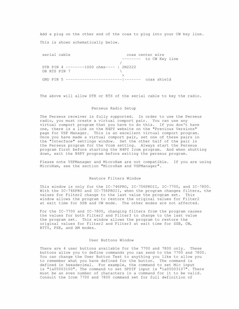
Add a plug on the other end of the coax to plug into your CW key line.
This is shown schematically below.
serial cable coax center wire -------- to CW Key line / DTR PIN 4 --------1000 ohms---- | 2N2222 OR RTS PIN 7 \ > GND PIN 5 ------------------------|------- coax shield
The above will allow DTR or RTS of the serial cable to key the radio.
Perseus Radio Setup
The Perseus receiver is fully supported. In order to use the Perseus radio, you must create a virtual comport pair. You can use any virtual comport program that you have to do this. If you don't have one, there is a link on the N4PY website on the "Previous Versions" page for VSP Manager. This is an excellent virtual comport program. Once you have made a virtual comport pair, set one of these pairs in the "Interface" settings window. Set the other half of the pair in the Perseus program for the Vcom setting. Always start the Perseus program first before starting the N4PY Icom program. And when shutting down, exit the N4PY program before exiting the perseus program.
Please note VSPManager and MicroHam are not compatible. If you are using MicroHam, see the section "MicroHam and VSPManager".
Restore Filters Window
This window is only for the IC-746PRO, IC-756PROII, IC-7700, and IC-7800. With the IC-746PRO and IC-756PROII, when the program changes filters, the values for Filter2 change to the last value the program set. This window allows the program to restore the original values for Filter2 at exit time for SSB and CW mode. The other modes are not affected.
For the IC-7700 and IC-7800, changing filters from the program causes the values for both Filter2 and Filter3 to change to the last value the program set. This window allows the program to restore the original values for Filter2 and Filter3 at exit time for SSB, CW, RTTY, PSK, and AM modes.
User Buttons Window
There are 4 user buttons available for the 7700 and 7800 only. These buttons allow you to define commands you can send to the 7700 and 7800. You can change the User Button Text to anything you like to allow you to remember what you have defined for the button. The command is defined in hexadecimal. For example, the command to set Mic input is "1a05003100". The command to set SPDIF input is "1a05003107". There must be an even number of characters in a command for it to be valid. Consult the Icom 7700 and 7800 command set for full definition of

these commands.
Alpha 87A Amplifier
There are special settings in the icom.ini file for using an Alpha 87A amplifier. If you have an this amplifier, with the program NOT running, open the icom.ini configuration settings file and find the line that says:
ALPHA 87A COMPORT=NONE
and change it to
ALPHA 87A COMPORT=COMx
where COMx is the actual comport number for the amplifier. Then save the change.
Now when you start the program, go to the "Call Sign, TopTen" settings window. Here you will see a line that is labelled "Alpha 87A".
There is an "Off" button, Clicking this button will change the button text to "On" and turn on the amplifier. Clicking this button button again will change the button text to "Off" and turn the amplifier off. If the amplifier is already on at program start, you can click this button to the on state and the amplifier will just stay on.
There is a "Oper" button. Clicking this will cause the button to turn red and set the amplifier in operate mode. Clicking it again will cause the button to go back to black and put the amplifier back in standby mode.
The amplifier will be polled once a second for power output. This value will be displayed just to the right of the "Oper" button.
The default baud rate for the amp is 4800. This can be change in the icom.ini configuration setting file by change the line
ALPHA 87A BAUD=4800
with the program NOT running.
Acom 2000 Amplifier (Older Acom specific command set)
There are special Acom 2000 settings in the "Usr5 TrnsV" settings window. Here you will find an "Acom 2000 Comport" check box and comport list box. If you are using the Acom 2000 Amplifier this is where you define the comport number for the amplifier. The program will run the comport at 1200 baud and send frequency information to the Acom 2000 amplifier. Connect the serial cable to the Acom amplifier serial connection. The serial cable must be a null modem cable and only use pins 2, 3, and 5. That is to say that pin 2 on one end goes to pin 3 on the other and vice versa. This will cause the Acom 2000 to follow the frequency of the radio without the need to transmit to set the frequency. Once you have made these changes to the program settings, exit and restart the program for these changes to take full effect.
Now when you start the program, go to the "Call Sign, TopTen" settings

window. Here you will see a line that is labelled "Acom 2000". There is a "Oper" button. Clicking this will cause the button to turn red and set the amplifier in operate mode. Clicking it again will cause the button to go back to black and put the amplifier back in standby mode.
Tokyo High Power Amplifier HL-1.5KFX and Acom 2000 Amplifier (using Newer Acom Kenwood command set)
There are special Tokyo High Power settings in the "Usr5 TrnsV" settings window. Here you will find a "Third Party Logging Comport" check box and comport list box. If you are using the Tokyo High Power Amplifier HL-1.5KFX or newer Acom amp, this is where you define the comport number for the HL-1.5KFX amplifier. The program will run the comport at 9600 baud and use a Kenwood interface to communicate with the amplifier. Connect the serial cable to the Kenwood amplifier serial connection and set the band control on the amplifier to "Kenwood". Do not turn on "Acom 2000 Comport" as this is only for the older Acom amp using the Acom specific command set.
The serial cable for the Tokyo High Power and Acom amp needs to be a null modem cable. That is pin 3 (transmit data) on the computer end needs to go to pin 2 (receive data) on the amp end. Also pin 5 for ground on the computer end needs to go to pin 5 on the amp end.
Using Steppir
Steppir antennas can be used with N4PY and Icom radios. The only N4PY setup required is to turn on the check box "Polling (Omni V.9 and Steppir only)". This setting is in the "Preferences3" settings window.
If you need a separate Steppir comport, go to the special Steppir settings in the "Usr5 TrnsV" settings window. Here you will find a "Separate Steppir Comport" check box and comport list box. If you are using the Steppir and need to use a separate comport for Steppir, this is where you define the comport number for the Steppir controller. The program will run the Steppir comport at 57600 baud and use a TenTec Orion interface to communicate with the Steppir controller. Connect the serial cable to the steppir "data in" port, not the data out port.
Palstar AT-Auto Tuner
The Palstart AT-Auto tuner can be controlled from the program. You will then need to set two parameters in the Icom.ini configuration settings file. Change this file only when the N4PY program is not running.
Find the line
PALSTAR COMPORT=NONE
and change it to
PALSTAR COMPORT=COMx where COMx is the actual separate comport you are using for the Palstar tuner.
Find the line
PALSTAR BAUD=9600
and change it to the actual baud rate you have selected in the tuner. Also, in the tuner setup, set it to Kenwood CAT only. Save the changes.
The program will send out the operating frequency to the amplifier once a second.
The serial cable for the tuner needs to be a standard straight through cable. That is pin 3 (transmit data) on the computer end needs to go to pin 3 (receive data) on the tuner end. Also pin 5 for ground on the computer end needs to go to pin 5 on the tuner end.
External Ports for other Programs Overview
The N4PY Control program has 5 external ports for hooking up digital programs, logging programs, panadapter programs, and CW skimmer. These external ports are called THP ports. The name "THP" comes from the first use of external ports for the Tokyo High Power amplifiers. The idea on hooking up programs through these ports is to simulate a Kenwood radio operating on a different comport. The ports are actually connected with a software cable called a virtual comport pair. Don't let the name scare you, it's just a fancy word for programs to share memory and communicate with each other. Virtual comports will work with any baud rate and serial settings so don't worry about the comport settings. Again this is simply because they are just memory transfers and not real serial ports at all. Anyway, all you need to make them is a program called VSPManager. This is a free program and there's a link on my "Previous Versions" page to send the author an email and ask him for it. Once you create a virtual comport pair (again it's really a software cable with a comport on each end), you put one of the comports as the radio comport in one program and the other comport in the N4PY control program as a THP port. The first THP port is set in the "Usr5 TransV" settings window. If you need more ports for more programs, the second to 5th port are set in the INI configuration settings file.
Third Party Logging Programs
The easiest way to interface a logging program with an N4PY control program is to use the Tentec File Interface. This can be done with any logging program that has a Tentec Pegasus listed as a supported radio. What you do is in the logging program, select the Tentec Pegasus as the radio type. Also, in the logging program you must set its transfer folder to c:\n4pyic of wherever you installed the N4PY control program. Once you do this, the logging program will no longer use a comport to communicate to the radio. Instead, it will communicate with the N4PY control program via a file. This is a very easy way to connect logging programs.
If the logging program does not support the Tentec Pegasus, then you can still hook up the logging program to the N4PY control program via a virtual comport pair. There is where for the Tokyo HP comport comes in. If you have a logging program such as N1MM or a digital program such as FLDigi that does not support the Tentec file interface, you can use this port in conjunction with the VSP Manager virtual comport driver to get the third party program to work with your radio and the N4PY control program at the same time. First, you need to install the virtual comport driver. You can get it on my website at www.n4py.com. Go to the "Previous Versions" page and there is a link to ask the author for it.
Please note VSPManager and MicroHam are not compatible. If you are using MicroHam, see the section "MicroHam and VSPManager".

Once this virtual comport driver is installed, it will give you a pair of comports to use. Use VSP Manager to define these comport pairs. In your logging program, set it for one of these comports and select a radio type of Kenwood TS-570 (Kenwood TS-50 for HRD, just "Kenwood" for N1MM). Set the other comport in the USR5 settings window for the Third Party Logging Comport. Also turn on the check box "Third Party Logging Comport". After these changes are made, exit and restart the program. Your third party logging program should now see the N4PY Icom program as though it was a Kenwood radio, regardless of the actual radio you are using.
If your third party logging program supports the K1EL winkey keyer, you can get it to send its CW messages to the N4PY program. This is done through K1EL keyer emulation in the N4PY program. First you make a virtual comport pair for this function. You can use any virtual comport program. If you don't have one, there is a link to VSP Manager on the "Previous Versions" page of the N4PY website. This is an excellent virtual comport program.
Once you have the virtual comport pair, define one of the pairs in the third party logging program as the K1EL keyer comport. Then with the N4PY program NOT running, open the icom.ini configuration file.
Find the line that says
EMUL K1EL=0
and change it to
EMUL K1EL=1
Next find the line that says
BOB COMPORT=NONE
and change it to
BOB COMPORT=COMx where COMx is the other half of the virtual comport pair. Then save the changes.
Now when you run the N4PY program, the CW messages sent in the third party logging program will come to the N4PY program. This is very useful when running remotely using the Client-Server function since this will cause the CW message characters to get sent to the N4PY server for transmission.
MicroHam and VSPManager
MicroHam and VSPManager are not compatible with each other. If you are using MicroHam you cannot create virtaul comport pairs with VSPManager. Instead, you create a "virtual cable" and turn on the TX check box in the "Create Virtual Cable" dialog of MicroHam. This action will give you a virtual comport pair just like VSPManager. You may need to reboot your computer after doing this so that Windows can get everything straight.
Using LP-Pan and PowerSDR-IF with your Radio
The PowerSDR-IF program has been replaced with NaP3. Follow instructions

for NaP3.
Using LP-Pan directly to NaP3 and also using N1MM and CW Skimmer all at the same time
The program has 4 additional THP comports that can be configured along with the main THP comport described above to allow other programs to operate with the N4PY program. These 2 additional comports can be used to run N1MM and CWSkimmer. These comports emulate a K3 radio to the other programs.
After you have setup the main THP comport for NaP3, create a second virtual comport pair. Configure one of these pairs in the N1MM comport setting. Configure the other half of this second comport pair in N4PY as follows:
With the N4PY program NOT running
1) Open the icom.ini configuration file 2) Find the line that says
THP2 COMPORT=NONE
and change it to
THP2 COMPORT=COMx where COMx is the other half of this second comport pair.
Then save the change.
If you then also want to use CWSkimmer, create a third virtual comport pair. Configure one of these pairs in the CWSkimmer comport setting. Configure the other half of this third comport pair in N4PY as follows:
With the N4PY program NOT running
1) Open the icom.ini configuration file 2) Find the line that says
THP3 COMPORT=NONE
and change it to
THP3 COMPORT=COMx where COMx is the other half of this third comport pair.
Then save the change. You will now be able to run the N4PY program along with NaP3, N1MM, and CWSkimmer all at the same time without the need to use LP Bridge.
There is also THP4 COMPORT=NONE and THP5 COMPORT=NONE that can be setup for more combinations.
Also if you want a THP port to send out VFO B frequency information for a THP port, find the line
THP VFOB PORT=0
and change it to

THP VFOB PORT=X where X is 1 to 5 depending on which THP port you want to follow VFO B. This is useful if you have a radio that has two receivers and you want CW Skimmer to follow the second receiver. Setting this to 0 turns this feature off.
VE7TK has done a great writeup at putting this all together. It is at <http://www3.telus.net/ve7tk/LP_PAN.pdf> This writeup is for the Orion but it still very appropriate with the Icom program. The main difference is in the Icom program, you must turn on the setting "Using NaP3".
Using any Flex Radio or SDR-IQ with your Icom Radio as a Panadapter
The "Third Party Logging Comport" comport can also be used with your Icom radio and Flex or RFSpace SDR-IQ radio as a panadaptor and sub-receiver. To use the Flex or SDR-IQ as a panadaptor, several steps must be done. They are as follows:
1) Install VSP Manager. I have a link to it on my "Previous Versions" page.
Please note VSPManager and MicroHam are not compatible. If you are using MicroHam, see the section "MicroHam and VSPManager".
2) Use VSP Manager to define these comport pairs.
for Flex radios: 3) Install the Flex radio with all its supporting software.
Configure PowerSDR for CAT using one of the comport pairs. In PowerSDR, turn on "Allow Kenwood AI Command". When running with PowerSDR, changing the mode or filter from the PowerSDR program does not change anything in the N4PY program. Mode changes in the N4PY program are sent to PowerSDR. Filter values are not sent to PowerSDR.
Or for SDR-IQ 3) Install all the SDR-IQ supporting software. This is the SDR-RADIO program from SDR-RADIO.COM
Configure the SDR-IQ software for HF Tracking using one of the VSP Manager comport pairs.
OR
Use Spectravue with "External Radio Setup"as Kenwood TS850/870/950. Keep Same Center Frequency, HF Tracking Mode, and Mode Tracking are check/enabled.
4) Configure the N4PY program's Third Party Logging Comport for the other virtual comport in the USR5 settings window for the Third Party Logging Comport. Also turn on the check box "Third Party Logging Comport". For Flex radios also turn on "PowerSDR Panadapter". For SDR-IQ radios, also turn on "SDR-IQ/HDSDR Pan". After these changes are made, exit and restart the program.
The Third Party Logging Comport will now communicate directly with

powerSDR or SDR-IQ. This will allow the Flex or SDR-IQ radio panadaptor to work very nicely with your Icom radio.
Using any HDSDR Radio with your Radio as a Panadapter
The Third Party Logging comport can also be used with your radio and any radio controlled with HDSDR as a panadaptor and sub-receiver. The setup requires several steps.
They are as follows:
1) Install VSP Manager. I have a link on my "Previous Versions" page for it.
Please note VSPManager and MicroHam are not compatible. If you are using MicroHam, see the section "MicroHam and VSPManager".
2) Use VSP Manager to define a comport pair. Let's assume you define COM10 and COM20. They can be anything as long as they are not used by anything else.
3) Install HDSDR and the panadapter radios drivers.
In HDSDR, in F7 Options, select "CAT to HDSDR". Set the PORT to one of the comport pairs (like COM10 in this example). Select "Activate". Make sure it shows a check mark. The baud rate does not matter with a virtual comport.
4) In the "Usr5 TransV" settings window configure the N4PY Icom program's Third Party Logging comport for the other half of the virtual comport pair (like COM20 in this example) for the Third Party Logging comport. Also turn on the check box "Third Party Logging Comport", If you are using an antenna connection to the SDR radio, turn on "SDR-IQ/HDSDR Pan". If you are using a a fixed IF output to the SDR radio, turn on "HDSDR Fixed IF". After these changes are made, exit and restart the program.
The Third Party comport will now communicate directly with HDSDR. This will allow the HDSDR radio panadaptor to work very nicely with your radio.
Using any SDRConsole Radio with your Radio as a Panadapter
The Third Party Logging comport can also be used with your radio and any radio controlled with SDRConsole as a panadaptor and sub-receiver. The setup requires several steps.
They are as follows:
1) Install VSP Manager. I have a link on my "Previous Versions" page for it.
Please note VSPManager and MicroHam are not compatible. If you are using MicroHam, see the section "MicroHam and VSPManager".
2) Use VSP Manager to define a comport pair. Let's assume you define COM10 and COM20. They can be anything as long as they are not used by anything else.
3) Install SDRConsole and the panadapter radios drivers.

In SDRConsole, in "Options", select Controllers and then "CAT" and then Port Selection. Set the PORT to one of the comport pairs (like COM10 in this example). The baud rate does not matter with a virtual comport.
4) In the "Usr5 TransV" settings window configure the N4PY Icom program's Third Party Logging comport for the other half of the virtual comport pair (like COM20 in this example) for the Third Party Logging comport. Also turn on the check box "Third Party Logging Comport", If you are using an antenna connection to the SDR radio, turn on "SDR-IQ/HDSDR Pan". After these changes are made, exit and restart the program.
The THP comport will now communicate directly with SDRConsole. This will allow the SDRConsole radio panadaptor to work very nicely with your radio.
Using NaP3 with the Tentec Omni VI as a Panadapter
The Third Party comport can also be used with your Omni VI and NaP3 as a panadaptor and sub-receiver. The setup requires several steps.
They are as follows:
1) Install VSP Manager. I have a link on my "Previous Versions" page for it.
Please note VSPManager and MicroHam are not compatible. If you are using MicroHam, see the section "MicroHam and VSPManager".
2) Use VSP Manager to define these comport pairs.
3) Install NaP3 and LP-Pan. Connect the Omni VI 9 mhz IF to LP-Pan and the outputs of LP-Pan to your sound card.
In NaP3 set the CAT PORT to one of the comport pairs. The baud rate does not matter with a virtual comport.
4) Configure the N4PY Icom program's Third Party logging comport for the other half of the virtual comport pair in the USR5 settings window for the Third Party logging comport. Also turn on the check box "Third Party Logging Comport", Turn on "NaP3 Panadapter". After these changes are made, exit and restart the program.
The Third Party comport will now communicate directly with NaP3.
Using the Microtelecom Perseus Receiver as a Panadapter
The Third Party Logging comport can also be used with your radio and Microtelecom's Perseus receiver as a panadaptor and sub-receiver. This radio is a great one to use because of its excellent receive characteristics. To use Perseus as a panadaptor, several steps must be done. They are as follows:
1) Install VSP Manager. I have a link to it on my "Previous Versions" page.

Please note VSPManager and MicroHam are not compatible. If you are using MicroHam, see the section "MicroHam and VSPManager".
2) Use VSP Manager to define a comport pair.
3) Install the Perseus radio with all its supporting software.
Configure the Perseus program for one of the virtual comport pairs. When running with Perseus, changing the mode or filter from the Perseus program does not change anything in the N4PY program. N4PY only picks up the frequency from the Perseus program. Frequency, mode, and filter changes in the N4PY program are sent to the Perseus program.
4) Configure the N4PY Icom program's Third Party Logging comport for the other virtual comport in the USR5 settings window for the Third Party Logging comport. Also turn on the check box "Third Party Logging Comport", "Use THP Comport for EXT Logging Program", and "Perseus Panadapter". After these changes are made, exit and restart the program.
The THP comport will now communicate directly with the Perseus program. This will allow the Perseus program panadaptor to work very nicely with your radio. Please note when split or dual is turned on in N4PY, the VFO B frequency will be sent to the perseus program. Likewise, with split or dual on in N4PY, N4PY will get the frequency from Perseus and put it in VFO B.
Antenna Hookup for a second radio to be used as a Panadapter
When using a Flex radio or Perseus receiver or HDSDR radio as a Panadapter, it is very advantageous to share the same antenna with the transceiver. If the transceiver is a 7600, 7700, or 7800 have an easy way to share antennas. For all other transceivers, the DXE-RTR-1A can be used to share antennas between the transceiver and the SDR receiver. This is a $170 unit that will provide a safe way to share antennas between the SDR receiver and transceiver.
Setup
1) Place the "Main On" switch in the middle "RX ANT" position. 2) Connect the amp key line of the transceiver to the "Transmit Ground" connection. 3) Connect a radio shack Y cable (part #42-2535) between the "Main ANT OUT" and "RX ANT IN" connections. 4) Connect the third leg of the Y cable to the antenna input of the SDR receiver.
SPE 1.3K, 1K-FA and 2K-FA Amplifiers
There are special Tokyo High Power settings in the "Usr5 TrnsV, Steppir" settings window. Here you will find a "Third Party Logging Comport" check box and comport list box. If you are using the SPE amps, this is where you define the comport number for the amplifier. Once you define the comport number, also turn on the "Third party Logging Comport" check box. The program will run the comport at 9600 baud and use a Flex radio interface to communicate with the amplifier. Connect the serial cable to the amplifier serial connection and set the band control on the amplifier to "Flex". The program will send out the operating frequency to the amplifier once a

second. Using the Flex radio interface allows the amplifier the send the radio power drive level. This drive level is received from the amplifier and sent to the radio. This allows the drive level to be automatically set for those radios that do not have and ALC input from the amplifier. If your radio does use ALC for the amplifier, then set the band control in the amplifier to "Kenwood".
Make a special cable with just 3 wires in it. The cable will have a female DB9 and a male DB15. Connect the pins together as follows:
DB9 DB15 pin 2 pin 9 pin 3 pin 1 pin 5 pin 4
The program will run the comport at 9600 baud and use a Kenwood radio interface to communicate with the amplifier. The program will respond to queries from the amplifier as though the radio were a Kenwood radio no matter what radio you are actually using.
Tokyo High Power Amplifier HL-1.5KFX and Acom 2000 Amplifier (using Newer Acom Kenwood command set) Ameritron ALS-1306
There are special Tokyo High Power settings in the "Usr5 TrnsV, Steppir" settings window. Here you will find a "Third Part Logging Comport" check box and comport list box. If you are using the Tokyo High Power Amplifier HL-1.5KFX or the newer Acom 2000 amp, or any of the SPE amps, this is where you define the comport number. Once you define the comport number, also turn on the "Third party Logging Comport" check box. The program will run the comport at 9600 baud and use a Kenwood interface to communicate with the amplifier. Connect the serial cable to the amplifier serial connection and set the band control on the amplifier to "Kenwood". The program will send out the operating frequency to the amplifier once a second.
The serial cable for the Tokyo High Power SPE, and Acom amp needs to be a null modem cable. That is pin 3 (transmit data) on the computer end needs to go to pin 2 (receive data) on the amp end. Also pin 5 for ground on the computer end needs to go to pin 5 on the amp end.
For the Ameritron ALS-1306, you can use the Ameritron Kenwood cable with a null modem adapter on the serial port end. Or you can make your own cable which is what I did. I made a cable with two female DB9's. I connected them as follows:
PC END ALS-1306 END
pin 3 to pin 3 pin 2 to pin 4 pin 5 to pin 6
Nothing else should be connected.
Bob S Meter

Woodbox radio at www.woodbox.com has a little program that produces a very nice looking analog S meter. This program can be run with N4PY software.
To use this Bob Smeter software, first go to www.woodbox.com (the exact link is on my website on the "Previous Versions" page) and download and install this program.
Then using any virtual comport program such as VSPManager, make virtual comport pair for the Bob Smeter. Set one of these pairs in the Bob Smeter program.
With the Icom program not running, go to the c:\n4pyic folder or wherever you installed the program and open the icom.ini configuration file.
Find the exact line that says:
BOB COMPORT=NONE
And change it to
BOB COMPORT=COMx
where COMx is the other comport for the virtual comport pair. Then save the change.
You start and stop the Bob Smeter with the second button from the left on the Bob Smeter window. Always start N4PY before starting the Bob Smeter. Always stop the Bob Smeter before stopping N4PY.
Change the timeout of 20 milliseconds in the Bob Smeter to 100.
S Meter Lite
There is also an interesting S meter program provided by W8WWV. There's a link for this on my previous versions page.
To use this S Meter software, first from my "Previous Versions" page download and install this program.
Then using a virtual comport program such as VSPManager, make virtual comport pair for the S Meter Lite. Set one of these pairs in the S Meter Lite program. Configure S Meter Lite for an Icom 756Pro, regardless of what radio you are actually using.
With the Icom program not running, go to the c:\n4pyic folder or wherever you installed the program and open the icom.ini configuration file.
Find the exact line that says:
BOB COMPORT=NONE
And change it to
BOB COMPORT=COMx
where COMx is the other comport for the virtual comport pair.

Find the Line
SMETER LITE=0
and change it to
SMETER LITE=1
Then save the change.
The S Meter Lite program will now work with the N4PY program.
4O3A Antenna Genius
The 4O3A Antenna Genius can be used as a software controlled antenna switch.
To setup the program for the 4O3A Antenna Genius:
1) With the program NOT running, open the icom.ini file and find the line that says:
4O3A AG=0
and change it to
4O3A AG=1
Also set the following line to the correct port and IP Address
4O3A AG PORT=9007 4O3A IP AG=192.168.1.250
3) Find the lines that say:
ANT 1 LOW=0 ANT 1 HIGH=0 ANT 2 LOW=0 ANT 2 LOW=0 Etc., and set the ranges for each antenna in mHz. For example if antenna 3 was to cover the 20 meter band, you should put
ANT 3 LOW=14.0 ANT 3 HIGH=14.35
If you have an antenna that needs more than one frequency range such as using an 80 meter antenna also on 30 meters. you can change the antenna that is assigned to each range.
Find the series of lines that say:
ANT RANGE 1=1 ANT RANGE 2=2 ANT RANGE 3=3 ANT RANGE 4=4 ANT RANGE 5=5 ANT RANGE 6=6 ANT RANGE 7=7
ANT RANGE 8=8
These lines assign the same range to the corresponding antenna by default. But if for example you wanted both range 3 and range 6 to control antenna 3, you would change
ANT RANGE 6=3
Save the changes to the icom.ini file.
The controls for Antenna Genius will show up in the "RTTY, KB settings" window of the settings menu. With "Auto" selected, the frequency ranges above will cause the particular antenna for that range to be selected. If you select any antenna by clicking on its button, the auto function is turned off and that antenna will remain selected even if you change frequencies. Just click the auto button again to restore automatic antenna selection back.
In the transmitter setting window, there is also a drop down box for Radio 1 and Radio 2. Use this to select which side of Antenna Genius is connected to a radio.
LDG Electronics DTS-4 and DTS-6 Coax Antenna Switch
The LDG DTS-4 and DTS-6 coax antenna switches are supported To setup the program for LDG coax switch:
1) With the program NOT running, open the icom.ini file and find the line that says:
LDG COAX COMPORT=
And change it to
LDG COAX COMPORT=COMx where x= the com number from 1 to 20
2) Find the lines that say:
ANT 1 LOW=0 ANT 1 HIGH=0 ANT 2 LOW=0 ANT 2 LOW=0 Etc., and set the ranges for each antenna in mHz. For example if antenna 3 was to cover the 20 meter band, you should put
ANT 3 LOW=14.0 ANT 3 HIGH=14.3
Save the changes to the icom.ini file.
The controls for the switch will show up in the "RTTY, KB Settings" window of the settings menu. With "Auto" selected, the frequency ranges above will cause the particular antenna for that range to be selected. If you select any antenna by clicking on its button, the auto function is turned off and that antenna will remain selected even if you change frequencies. Just click the auto button again to restore automatic antenna selection back.

Icom.ini file Parameters for the [OPERATING STATUS] section
The value for each parameter below is set to the default value. This is the value you get when the parameter is not defined. The text will indicate what other values are legal.
PEGASUS COMPORT=NONE
This parameter is in the [INTERFACE] section. It can be used to control the radio via a TenTec remote tuning knob connected to a TenTec Pegasus or Jupiter. This feature is only for people that happen to have a TenTec Pegasus or Jupiter with the remote tuning knob. It allows the tentec remote tuning pod to control the Icom radio. To enable this feature, you only have to specify the comport the Pegasus or Jupiter is connected to. For example, if you connect the Pegasus or Jupiter to com3 you would change this line to:
PEGASUS COMPORT=COM3
This feature only enables the TenTec Pegasus or Jupiter for remote pod usage. No other functions on the Pegasus or Jupiter are available.
PTT COMPORT=NONE
This parameter is in the [INTERFACE] section. It can be used to control PTT for CW keying using a separate comport. You can use either DTR or RTS to key the radio by selecting one of these two options from the INTERFACE window of the settings menu. For example, if you connect your PTT to com3 you would change this line to:
PTT COMPORT=COM3
LP500=1
If you have the Telepost LP-500 or LP-700 watt meter and want to use it, you can use this option. Find the line "LP500=0" in the icom.ini file. Set this line to LP500=1 and save the change. The program will read this watt meter during transmit and display the results in the S meter window during transmit.
LP100 COMPORT=COM2
If you have the Telepost LP-100A watt meter and want to use it, you can use this option. Find the line "LP100 COMPORT=NONE" in the "Interface" section of the icom.ini file. Set this line for the comport you are going to use for the LP-100A watt meter. The program will read this watt meter during transmit and display the results in the S meter window during transmit. If you have the older LP-100, in addition to this comport setting, change LP100=0 to LP100=1.
POWERMASTER COMPORT=COM2
If you have the PowerMaster watt meter and want to use it, you can use this option. Find the line "POWERMASTER COMPORT=NONE" in the "Interface" section of the icom.ini file. Set this line

for the comport you are going to use for the PowerMaster watt meter. The program will read this watt meter during transmit and display the results in the S meter window during transmit. Make sure the watt meter is set to 38400 baud.
AUTO PROGRAM START= AUTO PROGRAM START FOLDER=
These two parameters are used to define a program that you want started each time the program starts. For AUTO PROGRAM START, set this to the full path and file name of the executable you wish to start. Set AUTO PROGRAM START FOLDER to the full path name of the folder to be the default folder for the program.
Example: AUTO PROGRAM START=c:\abc\def.exe AUTO PROGRAM START FOLDER=c:\abc
The above example starts a program called def.exe in the c:\abc folder
K1EL F1=1 K1EL F2=2 K1EL F3=3 K1EL F4=4
These 4 entries define the function of the four K1EL winkey 2 buttons. Each of these 4 buttons will call the pod function assigned to corresponding computer function key. For example to make the left most keyer button (K1EL F1) perform the pod function assigned to the computer keyboard F8 key set
K1EL F1=8
This allows 4 functions to be performed even if the N4PY program does not have the keyboard focus.
AUTO START TUNER=0
This setting will cause a tuner start command to be sent to the radio when the "Tune" button is clicked on. To enable this feature set this as follows:
AUTO START TUNER=1
K1EL PTT=0
Setting this option to 1 will allow use of the K1EL keyer for PTT for those radios that do not have a software PTT command.
Frequency Event Timer
This option is selected with a check box in "Preferences3". This feature allows you to define frequency events and have the radio go to those frequencies when the time for the event occurs. This is very useful for unattended operation with a receiving radio on the internet. The frequency events are defined in a special file called "events.txt". This file is
created the first time you turn this option on with its check box. The file is located in the c:\n4py folder or wherever you have the program installed.
Once you have turned on the option the first time, exit the program, and edit the "events.txt" file to create frequency events. Do not edit the file with the program running. The file is column sensitive. Each time must be 2 numeric characters followed by a colon, followed by 2 numeric characters. There should then be one space followed by a frequency expressed in megahertz.
The events are defined by the day of the week. There can be up to 24 events for each day of the week. The file has a section for each day of the week and 24 events for each day. You should carefully edit the default lines with the values you want. All the default lines have a time of 00:00 and a frequency of 00.000. These times are in the local time of your computer and not in UTC. The times must be in 24 hour time with a range from 00:00 to 23:59. When program finds a match with the day of the week, hour, and minute, the program will change to the indicated frequency and set the corresponding default mode and filter.
D-Star operation for the IC-9100
I have added limited D-Star operation for the IC-9100. There is a mode button labelled "DV". This is for digital voice using D-Star. There is a setup window you for D-Star. Alt-J will make this window visible. In this window you define the "UR", "R1", "R2", and "MY" values for D_Star.
Recalling Icom Memories
You can recall an Icom memory directly from the radio. Alt-N will make the Icom memory window visible. You put a memory number in the Icom memory field and press enter. This will cause that Icom memory to be recalled in the radio. This is very useful for repeater operation on those Icom radios that cover repeater frequencies as you can have repeater frequencies, offsets, and sub-audible tones all preconfigured in these memories.
Memory File Usage
Memories are saved in files that are "RMY" file types. RMY files are binary files and are not editable with an editor. They save all the significant parameters for the station including "split status" and the transmit frequency. If you want to edit an RMY file, you must first export the file. See "Importing and Exporting Files" below. The "File" menu has several entries to control memory file usage. The memory file entries in the "File" menu are as follows:
New - Clicking this entry will allow you to start a brand new memory file. If the current memory file has not been saved to disk, you will be asked if you want to save it before the current memory is cleared.
Open - Clicking this entry will allow you to open a memory file that has been previously saved. You will be shown all the RMY file types that exist in the program working folder.
Close - Clicking this entry will save the current memory file contents

to disk and end usage of this memory file.
Save - Clicking this entry will save the current memory file contents to disk but still keep the memory contents in memory. This is useful to do just after you add a memory and want the disk to be updated with the new entry.
Save As - Clicking this entry will save the current memory file contents to disk but still keep the memory contents in memory. This is useful to do just after you add a memory and want the disk to be updated with the new entry. It also allows you to give the disk file a new file name.
Importing and Exporting Files
On the file menu, there is an Import and Export. These functions allow the ability to import and export files that are text files. This allows you to export the current memory files as a text file and then add more stations to it. You may get these files from any source and simply combine them by following the file format. Later, you may import this file back into memory and assign an RMY file name to it.
The format of the file is straight forward. An entry simply occupies a single line. Each line has ASCII text for the station name, station frequency in MHz, station mode, filter in hertz, country, language and optionally split frequency. Each value is separated by a comma with no extra spaces. Inspection of an existing file will show the format clearly.
To export an RMY file, first open the RMY file as follows: 1) Click on "File" 2) Click on "Open" 3) Select the RMY file you wish to open 4) Select OK
The above opens and loads the RMY file in memory. To export the RMY file, proceed as follows: 1) Click on "File" 2) Click on "Export" 3) Type in the name you wish for the CDF file 4) Select OK
To import a CDF text file, proceed as follows: 1) Click on "File" 2) Select "Import" 3) You should see the files of type CDF. 4) Select the file you wish to import and click OK.
If you then want to create an "RMY" file so that when you run the N4PY program next time you can get this file automatically selected, proceed as follows:
1) With the CDF loaded into memory as above, click "File". 2) Select "Save As" 3) Type in the name such as "NEWFILE.RMY" 4) Select OK
This will save the data in the RMY format. You can now make this file name the default memory file as follows:

1) Select "File" 2) Select "Open" 3) You should see "NEWFILE.RMY" 4) Select this file as click OK.
If you are a member of the ILG database (www.ilgradio.com), you can download an ASCII text version of their data. This is a file called "ilgstext.zip". I have a DOS utility program that can convert this database to a "CDF" file which can then be imported into the Icom radio control program. Send me an email if you would like to have this file converting program.
Saving and Restoring Icom Radio Memories
On the file menu, there are three entries for saving and restoring the Icom radio memories. They are as follows:
Save Icom Memories - Clicking this button will allow you to select a "CDF" file to save the memories in. The memories will be saved in a standard CDF file that can be used later to import files. It takes about 1 minute to save the 99 memories. The Icom radio memories are numbered 1 to 99. For the IC-7200 the memories go 1 to 199.
Restore Icom Memories - Clicking this button will allow you to select a "CDF" file to restore memories from the file to the Icom radio.
Abort Sav/Res Mems - Clicking this button while a "save memory" or "restore memory" operation is underway will abort the save or restore memory operation.
For IC-7000, there is a memory bank setting in the "Preferences" window of the settings menu. You can use this to select memory bank A to E for saving or restoring memories or you can set it to "All" to save or restore all Icom radio memories. If the memory bank values are in the CDF file for restore memories, then this value is ignored. There is full support for all memories including split status and 9 character memory names. See the "sam7000.cdf" sample file for the file format. Memories 5 and 7 in bank A are examples of split memories.
During the Save and Restore memory operations, the current memory will show as the text on the "Store" below, just to the left of the "Recall" button.
Antenna Rotor Control
Rotor control is available for all antenna rotors that use the HyGain DCU-1 serial protocol and also the M2 Rotor series. This includes the following rotors:
Green Heron Engineering RT-20 and RT-21 HyGain DCU-1 Idiom Press - RotorCard DXA Idiom Press - RotorCard SDX Idiom Press - RotorEZ MDS RC1 series digital rotor control box M2 Rotor series
To turn on rotor control, with the program not running, open the

"icom.ini" configuration settings file. Find the line that says:
ROTOR COMPORT=NONE
and change it to
ROTOR COMPORT=COMx
where COMx is the serial port that is connected to the rotor control box.
If you have the M2 rotor series, find the line that says:
M2 ROTOR=0
and change it to
M2 ROTOR=1 for the older M2 rotors and M2 ROTOR=2 for the newer ones.
also there are two lines to set software rotor limits. They are
ROTOR LOW LIMIT=0 ROTOR HIGH LIMIT=359
You can change these lines if you need to have a different range.
There is also a setting for rotor polling. It is
ROTOR POLL=1
Set this to 0 if rotor polling causes a calibration problem with your rotor.
There is an edit box in the "Call Sign, TopTen" configuration settings window that is labelled "Rotor Bearing". You can key in the value for the rotor bearing that you want here. Once you key this in, the rotor will turn to that location. If your rotor supports bearing feedback, the rotor display box (just to the right of the edit box) will always show the current rotor bearing. The edit box will show the last target bearing you typed in. This value is updated once every 5 seconds.
You can stop the rotor at any time by clicking on the "Stop" check box. This box is located to the right of the Rotor Bearing edit box. The check mark will go out almost immediately when the stop command is sent to the rotor.
For the M2 rotor series, there is also a "Moving" label that will appear to the right of the Rotor Bearing edit box when the rotor is moving.
If you also use the N4PY DXSpots program, you can click on the displayed bearing for any country in the DXSpots check window and this will also cause the rotor to move to that bearing.
ADR2200 Used as a Coax Antenna Switch
The ADR2200 serial port switch can be used as a software controlled antenna switch.

To setup the program for the ADR2200 coax switch:
1) With the program NOT running, open the icom.ini file and find the line that says:
LDG COAX COMPORT=
And change it to
LDG COAX COMPORT=COMx where x= the com number from 1 to 99
2) Find the line that says:
ADR2200=0
and change it to
ADR2200=1
3) Find the lines that say:
ANT 1 LOW=0 ANT 1 HIGH=0 ANT 2 LOW=0 ANT 2 LOW=0 Etc., and set the ranges for each antenna in mHz. For example if antenna 3 was to cover the 20 meter band, you should put
ANT 3 LOW=14.0 ANT 3 HIGH=14.35
If you have an antenna that needs more than one frequency range such as using an 80 meter antenna also on 30 meters. you can change the antenna that is assigned to each range.
Find the series of lines that say:
ANT RANGE 1=1 ANT RANGE 2=2 ANT RANGE 3=3 ANT RANGE 4=4 ANT RANGE 5=5 ANT RANGE 6=6 ANT RANGE 7=7 ANT RANGE 8=8 ANT RANGE 9=9 ANT RANGE 10=10
These lines assign the same range to the corresponding antenna by default. But if for example you wanted both range 3 and range 6 to control antenna 3, you would change
ANT RANGE 6=3
Save the changes to the icom.ini file.
The controls for the switch will show up in the "transmitter" window of the settings menu. With "Auto" selected, the frequency ranges above will cause the particular antenna for that range to be selected.

If you select any antenna by clicking on its button, the auto function is turned off and that antenna will remain selected even if you change frequencies. Just click the auto button again to restore automatic antenna selection back.
Additionally, there is a second range for selecting antennas that is controlled with the "A Ant"/"B Ant" button under the user buttons. If this button says "A Ant" then all the ranges as listed above are used to select the antenna position. If the "A Ant" button is clicked it will change to "B Ant" and a second set of ranges will be used. These ranges have names exactly like the above ranges but have a "B" added to them. The names are as follows:
ANTB 1 LOW=0 ANTB 1 HIGH=0 ANTB 2 LOW=0 ANTB 2 LOW=0 etc.
ANTB RANGE 1=1 ANTB RANGE 2=2 ANTB RANGE 3=3 ANTB RANGE 4=4 ANTB RANGE 5=5 ANTB RANGE 6=6 ANTB RANGE 7=7 ANTB RANGE 8=8 ANTB RANGE 9=9 ANTB RANGE 10=10
Again, this second set of ranges is used if the "A Ant"/"B Ant" button is set to "B Ant". The setting for this button is remembered by band.
ADR2100 Used as a Coax Antenna Switch
The ADR2100 serial port switch can be used as a software controlled antenna switch.
To setup the program for the ADR2100 coax switch:
1) With the program NOT running, open the icom.ini file and find the line that says:
LDG COAX COMPORT=
And change it to
LDG COAX COMPORT=COMx where x= the com number from 1 to 99
2) Find the line that says:
ADR2200=0
and change it to
ADR2200=2
3) Find the lines that say:

ANT 1 LOW=0 ANT 1 HIGH=0 ANT 2 LOW=0 ANT 2 LOW=0 Etc., and set the ranges for each antenna in mHz. These settings will be for port A on the ADR 2100. For example if antenna 3 was to cover the 20 meter band, you should put
ANT 3 LOW=14.0 ANT 3 HIGH=14.35
If you have an antenna that needs more than one frequency range such as using an 80 meter antenna also on 30 meters. you can change the antenna that is assigned to each range.
Find the series of lines that say:
ANT RANGE 1=1 ANT RANGE 2=2 ANT RANGE 3=3 ANT RANGE 4=4 ANT RANGE 5=5 ANT RANGE 6=6 ANT RANGE 7=7 ANT RANGE 8=8 ANT RANGE 9=9 ANT RANGE 10=10
These lines assign the same range to the corresponding antenna by default. But if for example you wanted both range 3 and range 6 to control antenna 3, you would change
ANT RANGE 6=3
Save the changes to the icom.ini file.
The controls for the switch will show up in the "transmitter" window of the settings menu. With "Auto" selected, the frequency ranges above will cause the particular antenna for that range to be selected. If you select any antenna by clicking on its button, the auto function is turned off and that antenna will remain selected even if you change frequencies. Just click the auto button again to restore automatic antenna selection back.
For port B on the ADR 2100, you will find another set of settings that all end in "PB" for port B. Only port A and port B are currently implemented in this program. The manual antenna controls only change the port A settings. The port B settings are always in automatic mode.
Denkovi USB 8 Relay Board used as a coax Antenna Switch
The Denkovi USB 8 relay board can be used as a software controlled antenna switch.
To setup the program for the Denkovi device:
With the program NOT running, open the icom.ini configuration

settings file and find the line that says:
1) Find the line that says:
DENKOVI=0
and change it to
DENKOVI=1
3) Find the lines that say:
ANT 1 LOW=0 ANT 1 HIGH=0 ANT 2 LOW=0 ANT 2 LOW=0 Etc., and set the ranges for each antenna in mHz. For example if antenna 3 was to cover the 20 meter band, you should put
ANT 3 LOW=14.0 ANT 3 HIGH=14.35
If you have an antenna that needs more than one frequency range such as using an 80 meter antenna also on 30 meters. you can change the antenna that is assigned to each range.
Find the series of lines that say:
ANT RANGE 1=1 ANT RANGE 2=2 ANT RANGE 3=3 ANT RANGE 4=4 ANT RANGE 5=5 ANT RANGE 6=6 ANT RANGE 7=7 ANT RANGE 8=8 ANT RANGE 9=9 ANT RANGE 10=10
These lines assign the same range to the corresponding antenna by default. But if for example you wanted both range 3 and range 6 to control antenna 3, you would change
ANT RANGE 6=3
Save the changes to the icom.ini file.
The controls for the switch will show up in the "transmitter" window of the settings menu. With "Auto" selected, the frequency ranges above will cause the particular antenna for that range to be selected. If you select any antenna by clicking on its button, the auto function is turned off and that antenna will remain selected even if you change frequencies. Just click the auto button again to restore automatic antenna selection back.
4O3A Rotator Genius
The 4O3A rotator Genius is configured in the icom.ini configuration settings file. Here's the setup.

Find the line that says:
4O3A RG=0
and change it to
4O3A RG=1
Also set the following line to the correct port and IP Address
4O3A RG PORT=9006 4O3A IP RG=192.168.1.250
Also ROTOR 4O3A=1 setting can be set to 1 or 2 to control the first or second rotator used by Rotator Genius.
There is an edit box in the "Call Sign, TopTen" configuration settings window that is labelled "Rotor Bearing". You can key in the value for the rotor bearing that you want here. Once you key this in, the rotor will turn to that location. Bearing feedback is shown in the rotor display box (just to the right of the edit box) and will always show the current rotor bearing. The edit box will show the last target bearing you typed in.
There is also a "Moving" label that will appear to the right of the Rotor Bearing edit box when the rotor is moving.
You can stop the rotor at any time by clicking on the "Stop" check box. This box is located to the right of the Rotor Bearing edit box. The check mark will go out almost immediately when the stop command is sent to the rotor.
There are special considerations for setting this up if Client-Server operator is used. See "Special Considerations for 4O3A Devices" in the CSRemote.pdf documentation file.
Using Top Ten Devices Antenna Control
There is an automatic antenna selection feature provided to allow users to use the automatic band decoder provided by Top Ten Devices. This unit allows you to have either an external amplifier or external antenna switch automatically follow the Icom radio frequency settings. This program offers full support for the parallel port with all windows versions.
Information on this band decoder can be found at
www.qth.com/topten/bdecoder.htm
Parallel port 1 is used to control the Top Ten device controller. This is enabled in one of two configurations by going to the "Call Sign, TopTen" window of the "settings" menu. Selecting "TopTen Devices Option 1", causes the bands marked on the Top Ten Devices controller to follow the Icom radio frequency precisely.
In option 1, the bands are selected as follows:
Frequency < 2 MHz selects band 1 Frequency >=2 MHz and < 4 MHz selects band 2

Frequency >=4 MHz and < 8 MHz selects band 3 Frequency >=8 MHz and < 12 MHz selects band 4 Frequency >=12 MHz and < 16 MHz selects band 5 Frequency >=16 MHz and < 20 MHz selects band 6 Frequency >=20 MHz and < 24 MHz selects band 7 Frequency >=24 MHz and < 26 MHz selects band 8 Frequency >=26 selects band 9
Selecting "TopTen Devices Option 2" causes a unique setup for controlling the device. In option 2, the bands are selected as follows:
Frequency < 200 kHz selects band 1 Frequency >=200 kHz and < 30 MHz selects band 2 Frequency >=30 MHz and < 55 MHz selects band 3 Frequency >=55 MHz and < 149 MHz selects band 4 Frequency >=149 MHz selects band 9
When a frequency change is detected, the new band setting is output to the parallel port. The Top Ten Automatic Band Decoder is plugged into this parallel port and responds to the information sent to the port.
This program includes drivers for the parallel port so you do not need to do anything to setup the parallel port.
LDG Electronics AT-200PC Autotuner
Setting the "Enable AT-200PC" check box in the "Transmitter" window of the "settings" menu will cause the memory tuner controls to appear at the lower left side of the radio panel. You must also set the correct comport for the AT-200PC.
The LDG AT-200PC must be at firmware version 1.9 or later for correct operation. See the LDG website for how to upgrade your tuner to this version.
When using this tuner, the program will remember the tuner antenna settings by band. In addition, when changing bands with the program band buttons, the last tuner setting for that band will be recalled automatically without transmitting. If for some reason, it is ever necessary to clear out the EEPROM in the LDG tuner, the "Clear Mem" button in the "Transmitter" section of the settings menu can be used for this purpose. This will clear out all tuner memories. This is necessary if you have changed antennas and want to setup new tuner memories. Also, it is recommended that you perform an "Auto Tnr" on each band you will operate. For bands 7 mhz and up, you should do one "Auto Tnr" in the CW portion and another one in the SSB portion for the band you use. For 80 meters, you should do an "Auto Tnr" for at each 100 khz interval. For 160 meters, you should do one at each 50 khz interval for the portion of the band you intend to use. All these "Auto Tnr" operations must be done with the correct antenna selected. Once these "Auto Tnr" functions have been done, it will not be necessary to do them again unless your antennas change.
There are 8 buttons. They are:
1) "Auto Tnr" - Left clicking this button will cause the memory tuner to go into auto tune mode. When the tune completes or 20 seconds go by, it will automatically stop. When it completes, the

store memory routine will automatically run to save the current settings for the particular memory range you are in. If the "Auto Tnr" button turns red after the tune operation is over, it indicates the tune operation failed and the tune needs to be done again. Also, if the "Auto Tnr" button remains blue, it indicates the program 20 second timer timed out without getting a response from the tuner. If you click the "Sto" button, the program will accept the settings from the failed tune.
2) "Bypass" - Left clicking this button will put the memory tuner into bypass mode, thus removing it from the output circuit. Click the "Rcl Tuner" button to put the tuner back in use.
3) "Ant1" - Left clicking this button will toggle between the tuner's antenna 1 and antenna 2 connection.
4) "Cap" - Left clicking this button will tweak the capacitor setting of the tuner "down" in value. Right clicking this button will tweak the capacitor setting "up" in value.
5) "Ind" - Left clicking this button will tweak the inductor setting of the tuner "down" in value. Right clicking this button will tweak the inductor setting "up" in value.
6) "HiZ" - Left clicking this button will cause to tuner to go to its "Lo Z" or low impedance setting. Left clicking again will cause the tuner to go to its "Hi Z" or high impedance setting. The descriptor on the button indicates the current impedance setting of the tuner.
7) "Sto" - Left clicking this button will cause to memory tuner to save its current settings for this frequency to memory. It is only necessary to use this button if the "touch up" cap and ind buttons have been used.
8) "Rcl Tnr" - Left clicking this button will cause the memory tuner to recall the last settings for this frequency from the tuner's memory. If the SWR is greater than 2.0, the "Auto Tnr" procedure will automatically be started to try and find a better match. If the "Auto Tnr" button turns red after the tune operation is over, it indicates the tune operation failed and the tune needs to be done again. If you click the "Sto" button, the program will accept the settings from the failed tune.
There is a tuning paramter in the icom.ini file to set the SWR threshold. Look for the line that says:
LDG SWR THRESH=50
To change the SWR threshold, change the value to one of the following:
50 = 1.1 51 = 1.3 52 = 1.5 53 = 1.7 This one seems to work the best for me 54 = 2.0 55 = 2.5 56 = 3.0
The default is 53 for 1.7 to 1 threshold.

LDG 1000Pro Automatic Tuner
The LDG 1000Pro Auto Tuner setting for antenna 1 or 2 can be controlled if you are using my LDG tuner program version 1.02. This version is available for free on my test page on my website.
To setup the Orion program for LDG 1000Pro Tuner:
1) With the program NOT running, open the icom.ini file and find the line that says:
LDG1000=0
And change it to
LDG1000=1
2) Find the lines that say:
ANT 1 LOW=0 ANT 1 HIGH=0 ANT 2 LOW=0 ANT 2 LOW=0 Etc., and set the ranges for each antenna in mHz. For example if antenna 2 was to cover the 20 meter band, you should put
ANT 2 LOW=14.0 ANT 2 HIGH=14.3
ANT RANGE 1=1 ANT RANGE 2=2 ANT RANGE 3=3 ANT RANGE 4=4 ANT RANGE 5=5 ANT RANGE 6=6 ANT RANGE 7=7 ANT RANGE 8=8
These lines assign the same range to the corresponding antenna by default. If for example you wanted both range 3 and range 6 to control antenna 2, you would change
ANT RANGE 3=2 ANT RANGE 6=2
Save the changes to the icom.ini file.
The controls for the switch will show up in the "transmitter" window of the settings menu. With "Auto" selected, the frequency ranges above will cause the particular antenna for that range to be selected. If you select any antenna by clicking on its button, the auto function is turned off and that antenna will remain selected even if you change frequencies. Just click the auto button again to restore automatic antenna selection back.
Woodbox Radio Tmate 2

Woodbox radio sells a very nice 3 knob pod with 6 buttons that is now supported in N4PY programs. To configure this pod, go to the "Remote Pod Fkeys" settings window and turn on the check box "Using Woodbox Radio Tmate2". Assuming the Tmate2 is already plugged into a USB port and it's drivers are installed, that's all you have to do.
Once the knob is configured and working, you can now customize the N4PY program to your liking. There are 3 pod setup windows to allow you to define the actions of the FlexControl buttons.
There are 9 buttons on the Tmate2 device. They are F1, F2, F3, F4, F5, F6, and the 3 knobs themselves.
The 3 pod settings windows allow you to select the actions for these buttons. These 3 pod settings windows are named "Knob Settings", "Function Keys", and "Knob Buttons". The main right knob, and the center knob are setup for single function. You define these single functions in their settings list box in the "Knob Settings" settings window. The left hand knob is meant to be a multi use knob. It's initial function is set with the "Left Multi Knob" list box. The current setting for the multi knob is always shown in the upper right hand corner of the black frequency area.
The "Function Keys" settings window contains the settings for the six F1 to F6 keys. Any knob function setting set from an F key will be assigned to the left multi knob only.
The "Knob Buttons" settings window contains the settings for the 3 knob buttons. Any knob function setting set from a knob button will be assigned to the left multi knob only. Please not that I found that the right Main tuning knob is very easy to accidentally push its button. I added a new pod setting called "No Op". Selecting this setting causes no operation to be be done. That's what I now use for the Main knob button.
The selections "UP B+1" and "UP B+5" are very nice for split DX pileups. "UP B+1" and "UP B+2" selections work together to give you a very nice UP frequency function. By setting say "F6" to "UP B+1" and "F5" to "UP B+2" (these are the default settings), when a DX station annouces he is listening say "up 3", you can simply press the "F6" button 3 times and VFO B will now be VFO A plus 3 and Split will now be on. Therefore, you can instantly set split operation for an exact amount by how many times you rapidly click "F6".
The exact action for "UP B+1" is if SPLIT is off, perform an A equal B and then add 1 to VFO B. If SPLIT is already on, then just add 1 to VFO B. And the "UP B+5" also does the same thing except it adds 5.
The "Tune Lock" LED on the pod is used as a "Split" indicator. When on "Split" is on. When off, "Split" is off.
There's an option in the "Knob Buttons" settings window to have the Tmate 2 S meter just read Peak readings.
There are also tuning parmameters in the Icom.ini configuration settings file. They are as follows:
TM2 RED=255 This controls how much red color is in the backlight.
The range is 0 to 255.
TM2 GREEN=255 This controls how much green color is in the backlight. The range is 0 to 255. TM2 BLUE=255 This controls how much green color is in the backlight. The range is 0 to 255. TM2 CONTRAST=0 This controls how much contrast is on the screen. The range is 0 to 255 with max contast at 0. TM2 SPEED 1=1 This controls the speed of the main tuning knob. It should always be set to 1. TM2 SPEED 2=20 This controls the multiplier when turning the main knob at speed 2.
TM2 SPEED 3=100 This controls the multiplier when turning the main knob at speed3.
TM2 THRESH 1 2=5 This controls the amount of counts that occur during the evaluation time period to where speed 2 kicks in. TM2 THRESH 2 3=10 This controls the amount of counts that occur during the evaluation time period to where speed 3 kicks in when already at speed 2. TM2 EVAL MS=100 This sets the evaluation time in milliseconds to decide on changing the knob speed to speed 2 or speed 3.
FlexControl Knob
Flex Radio sells a very nice knob that can be used to control any N4PY supported radio. This knob has a big advantage over the Griffin and Shuttle Pro knob because it tunes much nicer and does not have the "Focus" problem. That means this knob will still control the radio even when N4PY is running in the background. You can purchase this knob on the Flex radio website. Go to the Online Store and select "Accessories" to find it. N4PY Software has no connection with Flex Radio.
To install this FlexControl Knob Software Driver from the CD - 1) Insert the CD that canme with the FlexControl device. 2) When it asks what you want to install, uncheck all the boxes except "FlexControl". This is the only selection you want to make. 3) Run this installer to its completion.
OR
To install this FlexControl Knob Software Driver from the Internet -
1) Go to www.flex-radio.com 2) Scroll down and find "PowerSDR 2.x Integrated Installer". 3) Download and run this installer. 4) When it asks what you want to install, uncheck all the boxes except "FlexControl". This is the only selection you want to make. 5) Run this installer to its completion.
Now plug in the FlexControl USB connection to any USB connector on your computer.
For Windows Vista or 7, the computer should display a message saying

"Installing Device Driver." A few moments later a message will appear that says "FlexControl Driver is successfully installed" and "The device is ready for use."
For Windows XP, after plugging in the FlexControl for the first time, (or anytime in the future that a new USB port is used) the "Welcome to the Found New Hardware Wizard" will appear explaining that the "Wizard helps you install software for: FlexControl USB Control Knob".
Check "Install the software automatically." Then press "Next." This will result in a message that the "Wizard has finished installing the software for FlexControl USB Control Knob." Now press "Finish" to close the Wizard.
Once the Wizard completes the install, you must check to make sure there are no comport conflicts. You do this as follows.
1) Double click on "My Computer" 2) Click "View System Information". 3) Click the "Hardware" tab. 4) Click the "Device Manager" button. 5) Slide down to ports and see what comport was assigned for "FlexControl USB Control Knob". 6) If this comport conflicts with anything else you have installed previously, you must change it. 7) To change the FlexControl comport, A) Double click on "FlexControl USB Control Knob" B) Click the "Port Settings" tab. C) Click the "Advanced" button. D) Click the down arrow next to "COM Port Number". E) Select an unused comport. A high one is a good one to select. F) Click "Ok" on all opened windows. G) Reboot your computer and all shoule be well.
If there is ever a need to manually tell Windows where to find the driver files, tell Windows that the drivers are in:
C:\Program Files\FlexRadio Systems\PowerSDR v2.1.x\FlexControlyy
Where x is the dot release for the version of PowerSdr V2.1, and where yy is either 32 or 64, as is appropriate for the version of the Windows Operating system.
Operation of the FlexControl Knob in the N4PY program -
Once the driver and Flex knob are fully installed, start the N4PY program. Go to the settings window and then select "Remote Pod Fkeys". Check the box "Using FlexControl Knob".
Once you select this box, the N4PY program will search for the FlexControl device. If it finds it, the knob will now control your radio. If you get the error "FlexControl Knob not found" something is wrong with the software driver setup above.
Once the knob is configured and working, you can now customize the N4PY program to your liking. There are 3 pod setup windows to allow you to define the actions of the FlexControl buttons.
There are 4 buttons on the FlexControl device. They are Aux1, Aux2, Aux3, and the knob itself. Each button can be used with 3

different actions. A single click, a double click (like a mouse), and a long click (greater than a half second).
The 3 pod settings windows allow you to select the actions for these buttons. These 3 pod settings windows are named "Aux Single", "Aux Double, Long", and "Knob Clicks". The default action for the knob itself is a single click will set the knob to control VFO A. A double click will set the knob to control VFO B. A long click will set the knob to control pass band tuning. You can see the action for the knob in the upper right hand corner of the black frequency area.
There are special selections for the Aux Single, Double, and Long selections. These are "UP B+1", "UP B+2", and "UP B+5". The "UP B+1" and "UP B+2" selections work together to give you a very nice UP frequency function. By setting Aux3 Single to "UP B+1" and Aux3 Double to "UP B+2" (these are the default settings), when a DX station annouces he is listening say "up 3", you can simply press the Aux3 button 3 times (fast but not so fast as to get a double click) and VFO B will now be VFO A plus 3 and Split will now be on. Therefore, you can instantly set split operation for an exact amount by how many times you rapidly click Aux3.
The exact action for "UP B+1" is if SPLIT is off, perform an A equal B and then add 1 to VFO B. If SPLIT is already on, then just add 1 to VFO B. The "UP B+2" does the same thing except it adds 2 instead of 1. And the "UP B+5" also does the same thing except it adds 5. Once the "UP" operation is complete, the knob action is automatically set to VFO B. A single click of the knob itself get the knob action back to VFO A.
I recommend you use a label maker and label the 3 Aux buttons on the FlexControl device as an aid to remember their settings.
The 3 lights on the FlexControl knob are used to show the status for the single click actions for Aux1, Aux2, and Aux3. They will light only if Split, Dual receive, RIT, or PBT is on for that button. For example, if you have Aux1 Single defined for Split, the light above Aux1 will be on when Split it on and off when Split is off.
Ignore the text on these 3 lights as it is meaningless for this program.
You can also setup a fast tuning increase in step size to allow for very fast tuning.
To set this up, do the following: 1) In "Aux Single", make sure "Tuning Knob Desense Step Threshold" is at least 500. 2) In "Preferences4", set the "High Speed Tuning Factor" to a value that you want the step size increaded to. If you step size is normally 10, a value of 50 would increase the step size to 500 for very fast tuning. 3) In "Preferences4", set the sensitivity for how fast you move the knob before high speed kicks in. Normally, you will set this to a value between 2 and 20. The higher numbers are lower sensitivity.

Behringer CMD Micro MIDI DJ Controller
Behringer has a very nice DJ controller that is well suited as a ham radio controller. This device has 10 knobs and 20 buttons. To configure this pod, go to the "Remote Pod Fkeys" settings window and turn on the check box "Using Behringer MIDI Controller". Assuming the device is already plugged into a USB port, that's all you have to do.
Once the device is working, you can now customize the N4PY program to your liking. All the control setup is done using the cmdmicro.ini configuration settings file. This file is located in the folder where you installed the N4PY program and is not built until you turn on the "Using Behringer" option the first time. This file can be setup with the N4PY program either running or not running. If changes are made to the cmdmicro.ini file while the N4PY program is running, you can click the button "Reload CMD Micro Settings" once the changes have been saved in the file.
You can edit this file with notepad. The sliders are defined as "SLIDER1" being the left most slider and "SLIDER5" being the right most slider. All the other controls use the text as shown on the device itself. You can use a label maker and add labels to the controls as you like. I have provided a picture of an unmodified controller to allow you to see the original names on the controller. It is "picturecmemicro.jpg" and is in the folder where you installed the N4PY program.
The settings text must be exact from the list below for buttons but upper or lower case can be used freely.
Tuning Selections Tuning Steps Reverse Steps A/B Toggle A = B VFOA PBT ALC RIT VOL VFOB PTT VOX UP B+1 UP B+5 RF Gain Split Key Tuner On Tuner Off No Op TPF Band Bottom Up Numeric Down Numeric Keyer Speed Up Filter Down Filter Filter Tune XFC Mute Dual Receive Sto Sp1

Rcl Sp1 and Sto Sp2 Rcl Sp2
For the large left knob, large right knob, and the browse knob, the settings text is below.
* VFOA PBT ALC * RIT * XIT VOL * VFOB RF Gain Keyer Speed * Filter Tune
* Only the large left knob, large right knob, and browse knob can do these functions.
The browse knob is actually used as a multi function knob. If you define a button with a knob function setting, the browse button function will change to that function. The browse button current function is shown as small text in the upper right hand corner of the black frequency area.
The 5 sliders, the main level knob, and cue level knob cannot do all the above functions. They cannot do the ones labelled with as asterick above.
Not all functions above are available on all radios.
The selections "UP B+1" and "UP B+5" are very nice for split DX pileups. "UP B+1" and "UP B+5" selections work together to give you a very nice UP frequency function. By setting say "-" to "UP B+1" and "+" to "UP B+5" (these are the default settings), when a DX station annouces he is listening say "up 3", you can simply press the "-" button 3 times and VFO B will now be VFO A plus 3 and Split will now be on. Therefore, you can instantly set split operation for an exact amount by how many times you rapidly click "-".
The exact action for "UP B+1" is if SPLIT is off, perform an A equal B and then add 1 to VFO B. If SPLIT is already on, then just add 1 to VFO B. And the "UP B+5" also does the same thing except it adds 5.
Behringer Studio 2A MIDI DJ Controller
Behringer has a very nice DJ controller that is well suited as a ham radio controller. This device has 54 controls consisting of knob and buttons. To configure this pod, go to the "Remote Pod Fkeys" settings window and turn on the check box "Using Behringer MIDI Controller". Assuming the device is already plugged into a USB port, that's all you have to do.
Once the device is working, you can now customize the N4PY program to your liking. All the control setup is done using the studio2a.ini configuration settings file. This file is located in the folder where you installed the N4PY program and is not built until you turn on the "Using Behringer" option the first time. This file can be setup with the N4PY program either running or not running. If changes are made to the studio2a.ini file while the N4PY

program is running, you can click the button "Reload Behringer Settings" once the changes have been saved in the file.
You can edit this file with notepad. You can use a label maker and add labels to the controls as you like. I have provided a picture of an unmodified controller to allow you to see the original names on the controller. It is "picturestudio2a.jpg" and is in the folder where you installed the N4PY program.
The settings text must be exact from the list below for buttons but upper or lower case can be used freely.
Tuning Selections Tuning Steps Reverse Steps A/B Toggle A = B VFOA PBT ALC RIT VOL VFOB PTT VOX UP B+1 UP B+5 RF Gain Split Key Tuner On Tuner Off No Op TPF Band Bottom Up Numeric Down Numeric Keyer Speed Up Filter Down Filter Filter Tune XFC Mute Dual Receive Sto Sp1 Rcl Sp1 and Sto Sp2 Rcl Sp2
For the large left knob, large right knob, and the two pitch bend knobs, the settings text is below.
* VFOA PBT ALC * RIT * XIT VOL * VFOB RF Gain Keyer Speed * Filter Tune

* Only the large left knob, large right knob, and the 2 pitch bend knobs can do these functions.
The left pitch bend knob is actually used as a multi function knob. If you define a button with a knob function setting, this button function will change to that function. The left pitch bend button current function is shown as small text in the upper right hand corner of the black frequency area.
The 3 sliders and the knobs that have limits on how far they can turn cannot do all the above functions. They cannot do the ones labelled with as asterick above.
Not all functions above are available on all radios.
The selections "UP B+1" and "UP B+5" are very nice for split DX pileups. "UP B+1" and "UP B+5" selections work together to give you a very nice UP frequency function. By setting say pitch bend minus to "UP B+1" and pitch bend plus" to "UP B+5" (these are the default settings), when a DX station annouces he is listening say "up 3", you can simply press the "-" button 3 times and VFO B will now be VFO A plus 3 and Split will now be on. Therefore, you can instantly set split operation for an exact amount by how many times you rapidly click "-".
The exact action for "UP B+1" is if SPLIT is off, perform an A equal B and then add 1 to VFO B. If SPLIT is already on, then just add 1 to VFO B. And the "UP B+5" also does the same thing except it adds 5.
Program Support for the Griffin Technology PowerMate And also the Contour ShuttlePro Multifunction Controller
The Griffin Technology PowerMate and also the Contour ShuttlePro Multifunction Controller can be used for tuning the radio. However, I have found that a mouse with a spinning scroll wheel such as the Logitech MS 620 works better than either of these keyboard simulator controllers. Either keyboard contrller should be configured as follows:
RotateRight - SendKey with key value of Alt-G RotateLeft - SendKey with key value of Alt-B Click - SendKey with key value of Alt-I LongClick - SendKey with key value of Alt-Y
Example for setting up the Alt-G key in the Griffin Powermate configuration program:
The N4PY program must be active while this is done. Enter the correct file in the "Setting" window.
This is "icom" for all operating systems.
Then follow the procedure below: 1.User Action=rotate right 2.Computer Action=send key 3.Click "Change Key" 4.Checkmark in "Alt" 5.Type letter "g" (ignore upper/lower case. Ignore "Hint"). Do not put checkmark in "Shift".

Follow exactly this procedure using the letter "B" for "rotate left", the letter "I" for "click", and the letter "Y" for "long click".
Click "Apply Now". Click "OK"
Close PowerMate program. Open PowerMate program once again. Set "Sensitivity" at or near "fast. Click "Apply Now". Click "OK". Your finished. Note: If, when you are using the knob to change frequency and it tends to "run past" after you've stopped turning the knob, lower the sensitivity slightly until it operates properly.
The numeric keypad on the keyboard becomes the keys that go along with the PowerMate. If the keys are not reacting properly, you may have to click on the program radio panel to get the keyboard focus to the radio panel. Once the PowerMate is properly setup, you can now configure "Remote Pod 0-3" and "Remote Pod 4-9" to operate from the numeric keypad of the computer keyboard. Pressing the PowerMate knob down quickly will produce a click that the program will interpret as "period" key and follow the setting for ".". Likewise, pressing the PowerMate knob for a long click will cause an "F10" operation to be performed.
Once properly setup, you can use the PowerMate to change frequency, filters, RIT, PBT and many other things. You can still use the numeric keypad for direct frequency entry by pressing the "ENTER" key first.
You can purchase the PowerMate by going to www.griffintechnology.com.
WaveNode Watt Meter
The WaveNode watt meter is now supported. If you have a WaveNode watt meter, you can define this for use by opening the icom.ini configurtaion settings file. Find the line
WAVENODE=0
and change it to
WAVENODE=1
Then save the change.
Before starting the N4PY program, you must first start the wavenode program WN2.EXE, supplied by WaveNode. This is necessary since the wavenode program will send power and SWR messages to N4PY.
In the N4PY program, you can press Alt-Z to get the wavenode window. This window shows the SWR, average power, and peak power from the wavenode sensors. It also allows you to select which sensor will be shown in the S meter window during transmit. And it has a selection for "Use Peak Power". With this box checked, peak power will be shown in the S meter window during transmit. With this box not checked, average power will be shown.
Diagnostic Tracing

There is a check box in the "Preferences" window labelled "Diagnostic Tracing". This is used to gather trace information for Carl to debug a problem. When changing this setting, you have to exit and restart the program for the new setting to take effect. Turning this on causes tracing information to be written to the 3 trace files "comms.txt", "comms2.txt", and "comms3.txt". Only turn this on when you have been asked to by Carl.
Hot Keys on the keyboard
<Up-Arrow> Increase step size <Down-Arrow> Decrease step size <Left-Arrow> Tune Down <Right-Arrow> Tune Up <Shft-Left-Arrow> Fast Tune Down <Shft-Right-Arrow> Fast Tune Up <Ctl-Left-Arrow> Decrease Speaker Volume <Ctl-Right-Arrow> Increase Speaker Volume <-> Decrease Speaker Volume <+> Increase Speaker Volume <Alt => A=B <Alt /> A/B <Alt-A> AM Mode <Alt-C> CW Mode <Alt-E> Speech Proc <Alt-F> FM Mode <Alt-H> Show Message Box with this Menu <Alt-J> D-Star (9100 Only) <Alt-K> CW Keyboard Keyer <Alt-L> LSB Mode <Alt-M> Mute Audio <Alt-N> Recall Icom Memory <Alt-P> PTT Toggle <Alt-R> RTTY Mode <Alt-S> Split <Alt-T> ATTN <Alt-U> USB Mode <Alt-X> Quit <Alt-Z> Wave Node 0 - 9 Begin Entering Frequency F1 CW Keyboard Keyer Memory 1 F2 CW Keyboard Keyer Memory 2 F3 CW Keyboard Keyer Memory 3 F4 CW Keyboard Keyer Memory 4 F5 CW Keyboard Keyer Memory 5 <Shift F1> to <Shift F9> SSB Band Buttons <Ctrl F1> to <Ctrl F9> CW Band Buttons
For comments and suggestions email to [email protected]
Carl Moreschi N4PY 58 Hogwood Rd Louisburg, NC 27549