
N400 Basic Inspection
13
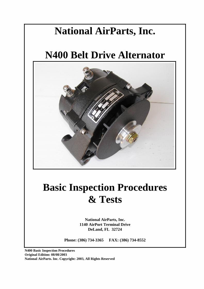
National AirParts, Inc. N400 Belt Drive Alternator Basic Inspection Procedures & Tests National AirParts, Inc. 1140 AirPort Terminal Drive DeLand, FL 32724 Phone: (386) 734-3365 FAX: (386) 734-8552 N400 Basic Inspection Procedures Original Edition: 08/08/2003 National AirParts. Inc. Copyright: 2003, All Rights Reserved
Transcript of N400 Basic Inspection
National AirParts, Inc.
N400 Belt Drive Alternator
Basic Inspection Procedures& Tests
National AirParts, Inc.1140 AirPort Terminal Drive
DeLand, FL 32724
Phone: (386) 734-3365 FAX: (386) 734-8552
N400 Basic Inspection ProceduresOriginal Edition: 08/08/2003National AirParts. Inc. Copyright: 2003, All Rights Reserved

Contents
PageItem
1. Alternator Description Page 2
2. Inspection Recommendations & Scope Page 2
3. Test & Inspection Equipment Requirements Page 2
4. Test Procedures Pages 3 & 4
5. Disassembly and Inspection Procedures Pages 5-9
6. Reassembly and Testing Pages 9-12
N400 Basic Inspection ProceduresOriginal Edition: 08/08/2003National AirParts. Inc. Copyright: 2003, All Rights Reserved Page 1 of 12

1. ALTERNATOR DESCRIPTION:
The National N400 alternators are heavy-duty, high output replacements for the Ford 95/100 amp alternators. The N400 mounts with the OEM mounting hardware, and generally requires only changes in the output and ground wire terminals to accomodate its 5/16-18 output studs.
Although the case dimensions for the National N400 are virtually identical to the Ford unit, the internal components are not directly interchangeable.
2. INSPECTION RECOMMENDATIONS
Preflight inspection typically should include an inspection of the alternator mounting hardware and electrical connections security. Special attention should be paid to the alternator pulley and drive belt to recognize any indication of belt slippage.
High output alternators require belts capable of handling the increased driverequirements. Only heavy-duty, high quality drive belts should be used, and belt tension should be checked regularly to insure maximum reliability. Belt tensions should be maintained at the level recommended by the airframe manufacturer for use of high output alternators.
Internal inspections of the alternator, as well as a detailed inspection of the alternator case, fan and pulley, should be performed each 500 operating hours, under normal operating conditions. This time interval should be decreased accordingly for severe or harsh operating environments, or any time undue wear or operating anonomalies are detected.
The internal inspection should include an inspection for the condition of the alternator brushes, bearings, rotor, stator and internal electrical connections.
3. TEST AND INSPECTION EQUIPMENT REQUIREMENTS
In addition to normal handtools, the following should be available in order to perform basic inspection and maintenance:
(a.) A calibrated Simpson 260 analog multimeter, or its equivalent (do NOT substitute a digital meter)
(b.) A calibrated torue wrench, 0-150 in lbs range
(c.) An air wrench which can be accurately set to between 65 and 85 ft lbs (for pulley removal and installation)
N400 Basic Inspection ProceduresOriginal Edition: 08/08/2003National AirParts. Inc. Copyright: 2003, All Rights Reserved Page 2 of 12

4. TEST PROCEDURES:
Normal electrical system and alternator troubleshooting procedures outlined in the airframe maintenance manual are generally applicable, and should be followed.
A quick verification of the basic alternator FIELD and output circuit condition can be performed with an analog multimeter such as the Simpson 260, set to read RESISTANCE on the X1 scale. Refer to the following photos and procedures:
(a.) FIELD RESISTANCE CHECK
(i.) Remove the alternator FIELD plug from the alternator.(ii.) Connect the meter between the alternator ground and the FIELD terminal as shown. Meter polarity is NOT important.(iii.) Resistance reading should be 5 ohms +/- 10% for HIGH OUTPUT rotors, and typically 11 ohms +/- 10% for 100 amp alternators. Resistance readings of less than 4.5 ohms for ANY rotor indicate a rotor short, and would be grounds for a detailed internal inspection of the alternator, with a probable rotor replacement being required. Readings ABOVE those indicated are common, as a result of slip ring filming, but should NOT be infinite or “open circuit”.
N400 Basic Inspection ProceduresOriginal Edition: 08/08/2003National AirParts. Inc. Copyright: 2003, All Rights Reserved Page 3 of 12

(b.) OUTPUT CIRCUIT DIODE & STATOR CHECK
(i.) Disconnect the output ring terminal from the alternator BAT stud.(ii.) Connect the Simpson 260 multimeter as shown, with the (+) meterprobe on the BAT terminal and the (-) on the GROUND stud. The reading should be INFINITE on the Resistance X1 scale.(iii.) Connect the meter (+) lead to the AUX terminal , with the (-) meter probe an the GROUND stud. The reading should also be INFINITE. NOTE: AUX terminal may be EITHER a connection terminal on the alternator rear case, or the marked “STA” position of the FIELD terminal.(iiii.) Reverse the meter polarity and perform the preceeding two tests again. The reading for the BAT terminal should be approximately 30-35 ohms, and the reading at the AUX terminal should be approximately 8 ohms +/- 10%.
Output Circuit Test
N400 Basic Inspection ProceduresOriginal Edition: 08/08/2003National AirParts. Inc. Copyright: 2003, All Rights Reserved Page 4 of 12

5. DISASSEMBLY & INSPECTION PROCEDURES:
The following procedures should be used as a guide for inspection of the alternator and its internal components. (Also refer to the National AirParts N400 Fan Installation Manual for information applicable to fan installation.)
(a.) Prepare a bench fixture to hold the alternator with its rotor shaft in a vertical position for ease in proper disassembly and assembly. A 1”+ thickness board with a 1 1/2” hole bored in it are suitable; see following photo as example:
(b.) Place the alternator on the holding fixture, pulley down, with the pulley nut placed in the fixture’s bored hole
N400 Basic Inspection ProceduresOriginal Edition: 08/08/2003National AirParts. Inc. Copyright: 2003, All Rights Reserved Page 5 of 12

(c.) Remove safety wire and screws holding cooling blast tube, if alternator is so equipped
Blast Tube Removal on Holding Fixture
(d.) Remove safety wire on thru bolts if alternator uses cap-screw thru bolts with safety wire, and remove and retain thru bolts and washers. Remove locknuts, washers and thru bolts for thru bolts using this type of hardware.
Thru Bolt removal on holding fixture. Thru bolt installation uses same procedure.
N400 Basic Inspection ProceduresOriginal Edition: 08/08/2003National AirParts. Inc. Copyright: 2003, All Rights Reserved Page 6 of 12

(e.) The alternator SRE (Slip Ring End) can now be removed from the alternator. A screwdriver may be used to lightly pry the case halves apart, with the screwdriver prying lightly between the stator stack and the drive end; the stator should be held in place with the SRE as it is being removed. NOTE: This disassembly procedure may be accomplished more easily, in some instances, if the alternator is first removed from the holding fixture andplaced on its side.
(f.) Place the SRE on the bench, with the SRE back lying flat on the bench, and inspect the SRE interior; see following photo:
(g.) Note that the brushes are extended and exposed, and that the rear brush is NOT a captive assembly, i.e. its spring may become dislodged, and fall from the brush holder.
N400 Basic Inspection ProceduresOriginal Edition: 08/08/2003National AirParts. Inc. Copyright: 2003, All Rights Reserved Page 7 of 12

(h.) Inspect the condition of the brushes. If they are broken, damaged, or worn beyond limits (0.2” O.A. Length minimum), the brush assembly should be replaced.
(i.) Inspect the SRE bearing pocket for contamination or obvious wear. No attempt should be made to relubricate the SRE bearing; if its condition is questionable, it should be replaced.
(j.) Inspection the stator windings for any discoloration or indications of heat damage.
(k.) Inspect stator connections and diode leads for integrity of connections.
(l.) The alternator Drive End and rotor should now be inspected. Verify smooth bearing operation by spinning the rotor by hand. Examine the slip rings for udue wear. Inspect the rotor winding wrap for any indication of discoloration or overtemperature operation. (See following photos)
Drive End Visual Inspection
N400 Basic Inspection ProceduresOriginal Edition: 08/08/2003National AirParts. Inc. Copyright: 2003, All Rights Reserved Page 8 of 12

(m.) The rotor resistance can now be more accurately measured, without brush resistance involved. Insure that the slip rings are wiped dry with a clean cloth, and verify resistance readings, as per Page 3.
(n.) If inspection shows any of the above to be questionable or unserviceable, the alternator should be returned to National AirParts for IRAN or Overhaul, as appropriate, or the components should be replaced I.A.W. the National AirParts N400 Alternator Overhaul Manual.
6. REASSEMBLY and TESTING
(a.) Prepare a brush retaining pin wire to use for securing the brushes. (A straightened paper clip can be used for this purpose.) This wire will be inserted from the back of the SRE case to secure the brushes once they have been installed. (See following photo)
Brush Retaining Pin Installed to Hold Brushes In Place
N400 Basic Inspection ProceduresOriginal Edition: 08/08/2003National AirParts. Inc. Copyright: 2003, All Rights Reserved Page 9 of 12

(b.) The brushes must now be reinserted in the brush holder. Insure that the rear brush spring is seated fully in its slot, carefully reposition the rear brush over the spring, and slide it fully into the slot. Be certain that the brush shunt slides into the rear groove provided for it, and does not “hang up” overthe edge of the brush holder. Note that, at this time, the front brush does not necessarily require being fully in position.
THIS IS A SOMETIMES PAINSTAKING PROCEDURE. DO NOT ATTEMPT TO HOLD OR POSITION THE BRUSHES WITH PLIERS OR FORCEPS SINCE THE BRUSHES ARE FRAGILE AND EASILY DAMAGED.
(c.) Insert the brush holding pin from the back of the SRE only far enough tohold the rear brush. Correctly position and “nest” the front brush, and insertthe brush retaining pin completely, so as to secure both brushes. It is usually convenient to bend the end of a cotter pin, as shown, to help hold the brushesfully seated while the brush retaining pin is inserted. (See following photo)
Brush Seating Tool
N400 Basic Inspection ProceduresOriginal Edition: 08/08/2003National AirParts. Inc. Copyright: 2003, All Rights Reserved Page 10 of 12

(d.) The alternator Drive End should now be properly placed, pulley down, on the holding fixture. (Reference Page 6.) After insuring that the slip rings and SRE bearing shaft surface are clean, the SRE may be lowered onto the drive end.
DURING THIS PROCESS, HOLD THE STATOR IN PROPER POSITION,FULLY SEATED IN THE SRE. The SRE should be aligned in the proper clocking position before being lowered onto the Drive End, as in the followingphoto.
(e.) Insert the thru bolts in the alternator. Capscrew thru bolts use an SS split lockwasher under the head. Thru bolts utilizing locknuts are inserted from the fan end of the drive end, and use a split lockwasher under the head and a flat washer under the locknut.
N400 Basic Inspection ProceduresOriginal Edition: 08/08/2003National AirParts. Inc. Copyright: 2003, All Rights Reserved Page 11 of 12
#1#1
#2
#3
#4

(f.) Torque the thru bolts using a torquing pattern similar to the one shown by the numbers in the preceeding photo. This provides a self-centering actionfor the stator alignment, and will tend to prevent any rotor-to-stator interference.
(i.) Capscrew type thru bolts should be initially tightened to approximately 50 inch lbs, and then fully torqued to 100 inch lbs, +/- 5 inch lbs.
(ii.) Thru bolts with locknuts should be initially torqued to approximately 35 inch lbs, then fully torqued to 65-70 inch lbs.
(g.) Safety wire capscrew-type thru bolts; apply torque seal to locknuts on applicable thru bolts.
(h.) Reinstall blast tube with original hardware; torque AN500 retaining screws to 2-3 inch lbs, safety wire screws and apply torqueseal.
(i.) Repeat FIELD and STATOR/DIODE TEST, as indicated on Pages 3 and 4, in order to verify operating measurements.
This concludes the N400 basic alternator Inspection and Testing. For additional technical help, call National AirParts, Inc., at 1-800-713-1111, or FAX at (386)-734-8552. Also, be certain to check the relevant pages of the National website, http://www.nationalairparts.com , for the latest technical updates.
--------------------- END -----------------------
N400 Basic Inspection ProceduresOriginal Edition: 08/08/2003National AirParts. Inc. Copyright: 2003, All Rights Reserved Page 12 of 12