N04C-# Engine COMMON RAIL SYSTEM (CRS) SERVICE … N04C- Engine.pdf · COMMON RAIL SYSTEM (CRS)...
64
COMMON RAIL SYSTEM (CRS) SERVICE MANUAL: Operation N04C-# Engine Applicable Vehicle : Manufacturer Vehicle Name TOYOTA DYNA COASTER HINO DUTRO Issued : March 2007 Revised : December 2009 00400058EB
Transcript of N04C-# Engine COMMON RAIL SYSTEM (CRS) SERVICE … N04C- Engine.pdf · COMMON RAIL SYSTEM (CRS)...
COMMON RAIL SYSTEM (CRS) SERVICE MANUAL: Operation
N04C-# Engine
Applicable Vehicle :Manufacturer Vehicle Name
TOYOTADYNACOASTER
HINO DUTRO
Issued : March 2007Revised : December 2009
00400058EB

© 2009 DENSO CORPORATIONAll rights reserved. This material may not be reproduced or copied, in whole or in part, without the written permission of DENSO Corporation.
Revision HistoryDate Revision Contents
2007.03 • Basic CRS content omitted, March, 2007 model CRS content added.Items added are as per the following:
APPLICABLE VEHICLES AND PRODUCT INFORMATIONMain components and SensorsEXHAUST GAS CONTROL SYSTEM (FEBRUARY 2007, JUNE 2009)“Engine ECU External Wiring Diagram” and “Connector Terminal Layout”ENGINE ECU DIAGNOSTIC TROUBLE CODES (DTC)
2009.12 • Basic CRS content omitted, June, 2009 model CRS content added.Items added are as per the following:
APPLICABLE VEHICLES AND PRODUCT INFORMATIONINJECTOR“Engine ECU External Wiring Diagram” and “Connector Terminal Layout”

Table of Contents
Operation Section
1. APPLICABLE VEHICLE AND PRODUCT INFORMATION1.1 Introduction . . . . . . . . . . . . . . . . . . . . . . . . . . . . . . . . . . . . . . . . . . . . . . . . . . . . . . . . . . . . . . . . . . . . . . . . . . . . 1-1
1.2 Applicable Vehicles . . . . . . . . . . . . . . . . . . . . . . . . . . . . . . . . . . . . . . . . . . . . . . . . . . . . . . . . . . . . . . . . . . . . . . 1-1
1.3 Applicable Product List . . . . . . . . . . . . . . . . . . . . . . . . . . . . . . . . . . . . . . . . . . . . . . . . . . . . . . . . . . . . . . . . . . . 1-2
2. SYSTEM OUTLINE2.1 Layout of Main Components . . . . . . . . . . . . . . . . . . . . . . . . . . . . . . . . . . . . . . . . . . . . . . . . . . . . . . . . . . . . . . . 1-5
3. SUPPLY PUMP3.1 Outline . . . . . . . . . . . . . . . . . . . . . . . . . . . . . . . . . . . . . . . . . . . . . . . . . . . . . . . . . . . . . . . . . . . . . . . . . . . . . . . . 1-6
3.2 Suction Control Valve (SCV) . . . . . . . . . . . . . . . . . . . . . . . . . . . . . . . . . . . . . . . . . . . . . . . . . . . . . . . . . . . . . . . 1-7
3.3 Fuel Temperature Sensor . . . . . . . . . . . . . . . . . . . . . . . . . . . . . . . . . . . . . . . . . . . . . . . . . . . . . . . . . . . . . . . . 1-10
4. RAIL4.1 Outline . . . . . . . . . . . . . . . . . . . . . . . . . . . . . . . . . . . . . . . . . . . . . . . . . . . . . . . . . . . . . . . . . . . . . . . . . . . . . . . 1-11
5. INJECTOR5.1 Outline . . . . . . . . . . . . . . . . . . . . . . . . . . . . . . . . . . . . . . . . . . . . . . . . . . . . . . . . . . . . . . . . . . . . . . . . . . . . . . . 1-12
6. CONTROL SYSTEM6.1 Control System Diagram . . . . . . . . . . . . . . . . . . . . . . . . . . . . . . . . . . . . . . . . . . . . . . . . . . . . . . . . . . . . . . . . . 1-15
6.2 Engine ECU. . . . . . . . . . . . . . . . . . . . . . . . . . . . . . . . . . . . . . . . . . . . . . . . . . . . . . . . . . . . . . . . . . . . . . . . . . . 1-16
6.3 Electronic Drive Unit (EDU) . . . . . . . . . . . . . . . . . . . . . . . . . . . . . . . . . . . . . . . . . . . . . . . . . . . . . . . . . . . . . . . 1-17
6.4 Sensors . . . . . . . . . . . . . . . . . . . . . . . . . . . . . . . . . . . . . . . . . . . . . . . . . . . . . . . . . . . . . . . . . . . . . . . . . . . . . . 1-18
7. EXHAUST GAS CONTROL SYSTEM (FEBRUARY 2007, AND JUNE 2009)7.1 Outline . . . . . . . . . . . . . . . . . . . . . . . . . . . . . . . . . . . . . . . . . . . . . . . . . . . . . . . . . . . . . . . . . . . . . . . . . . . . . . . 1-23
7.2 E-EGR System . . . . . . . . . . . . . . . . . . . . . . . . . . . . . . . . . . . . . . . . . . . . . . . . . . . . . . . . . . . . . . . . . . . . . . . . 1-23
7.3 DPF System . . . . . . . . . . . . . . . . . . . . . . . . . . . . . . . . . . . . . . . . . . . . . . . . . . . . . . . . . . . . . . . . . . . . . . . . . . 1-24
8. ENGINE ECU DIAGNOSTIC TROUBLE CODES (DTC)8.1 DTC Table . . . . . . . . . . . . . . . . . . . . . . . . . . . . . . . . . . . . . . . . . . . . . . . . . . . . . . . . . . . . . . . . . . . . . . . . . . . . 1-26
9. CONTROL SYSTEM COMPONENTS9.1 Engine ECU External Wiring Diagram. . . . . . . . . . . . . . . . . . . . . . . . . . . . . . . . . . . . . . . . . . . . . . . . . . . . . . . 1-33
9.2 Connector Terminal Layout . . . . . . . . . . . . . . . . . . . . . . . . . . . . . . . . . . . . . . . . . . . . . . . . . . . . . . . . . . . . . . . 1-57

Operation Section1–1
1. APPLICABLE VEHICLE AND PRODUCT INFORMATION
1.1 Introduction
This manual describes the Common Rail System (CRS) equipped with the NO4C-# engines used in the
HINO DUTRO, TOYOTA DYNA (both pickup trucks), as well as the TOYOTA COASTER (bus.)
For information on items common to all CRSs, refer to the previously published CRS general addition
manual (Doc ID: 00400076E). [Items common to all CRSs: CRS development process, system control,
construction and operation of main components (supply pump, rail, injectors.)]
1.2 Applicable Vehicles
November 2003
March 2007
June 2009
Vehicle Name Engine Model Remarks
DUTRO/DYNA N04C-TF
Vehicle Name Engine Model Destination Remarks
DUTRO/DYNA
N04C-TP
Europe
Vehicle power supply voltage: 24 V, EngineECU 12 V spec., with Diesel Particulate Filter(DPF), MT
N04C-TQ Vehicle power supply voltage: 24 V, MT withDPF
N04C-TR
GeneralVehicle power supply voltage: 24 V, EngineECU 12 V spec., MT
N04C-TS
N04C-TT
N04C-TU
Australia
Vehicle power supply voltage: 24 V, EngineECU 12 V spec., AT
N04C-TVVehicle power supply voltage: 24 V, EngineECU 12 V spec., MT
N04C-TW Europe, Hong KongVehicle power supply voltage: 24 V, EngineECU 12 V spec., with DPF, MT
COASTER
N04C-TQ Europe, Australia Vehicle power supply voltage: 24 V, with DPF,MT
N04C-TY China Vehicle power supply voltage: 24 V, MT
Vehicle Name Engine Model Remarks
DUTRO/DYNA/COASTER N04C-#

Operation Section1–2
1.3 Applicable Product List
November 2003
March 2007
Part Name DENSO Part Number Manufacturer Part Number Remarks
Supply Pump 294000-019# S2273-01264
Rail 095440-049# 22760-1170A
Injector 095000-532# 23910-1271A
Engine ECU 175800-658# 89660-37460
Electronic Drive Unit (EDU) 101310-539# 89870-37030
Accelerator Pedal Module 198800-315# 78100-37550
Crankshaft Position Sensor 029600-136# 89410-1630A
Camshaft Position Sensor 949979-131# 89410-1570A
Coolant Temperature Sensor 071560-011# 83420-1250A
Mass Air Flow (MAF) Meter 197400-200# 22204-21010
Intake Air Temperature Sensor 071500-249# 89441-4310A
Manifold Absolute Pressure(MAP) Sensor
079800-589# 89390-1080A
Exhaust Gas Recirculation(EGR) Valve
135000-705# 17350-1170A
Exhaust Gas TemperatureSensor
265600-060# (IN) 89441-37020 (IN)
265600-053# (OUT) 89441-37030 (OUT)
Part NameDENSO Part
Number
Manufacturer
Part NumberRemarks
Supply Pump 294000-059# 22100-E0060
294000-063# 22100-E0080 China Only
Rail 095440-098# 23810-E0010
Injector 095000-651# 23670-E0080
095000-652# 23670-E0090 General Only
095000-655# 23670-E0190 China Only

Operation Section1–3
EngineECU
DYNA/DUTRO
175800-799# 89661-37540 N04C-TQ, DPFVehicle power supplyvoltage: 24 V
175800-881# 89661-37590 N04C-TP, DPF
Vehicle power supply voltage: 24 V, Engine ECU 12 V specs.
175800-897# 89661-37600N04C-TW, DPF
175800-899# 89661-37610
175800-900# 89661-37620 N04C-TS
175800-902# 89661-37630 N04C-TT
175800-904# 89661-37640N04C-TV
175800-906# 89661-37650
175800-907# 89661-37550 N04C-TR
175800-909# 89661-37560 N04C-TS
175800-910# 89661-37570N04C-TU
175800-912# 89661-37580
EngineECU
COASTER 175800-863# 89661-36200N04C-TQ, DPF
Vehicle power supplyvoltage: 24 V175800-864# 89661-36210
175800-865# 89661-36180 N04C-TYVehicle power supplyvoltage: 12 V
175800-924# 89661-36220 N04C-TQ, DPFVehicle power supplyvoltage: 24 V
EDU 101310-539# 89870-37030 N04C-TQ
101310-571# 89870-37080
Accelerator PedalModule
198800-309# 78120-35460
198800-315# 78100-37750 N04C-TQ
EGR Valve 135000-721# 25620-E0010 Without N04C-TR, TS, TT
Camshaft PositionSensor
949979-131# 89410-1570A
Crankshaft PositionSensor
029600-136# 89410-1630A
MAF Meter 197400-200# 22204-21010
Exhaust GasTemperature Sensor
265600-053# 89425-37021 DPF, Upstream of Catalyst
265600-054# 89425-37031 DPF, Downstream of Catalyst
Differential PressureSensor
104990-102# 89480-37010DPF
Part NameDENSO Part
Number
Manufacturer
Part NumberRemarks

Operation Section1–4
June 2009
Part NameDENSO Part
Number
Manufacturer
Part NumberRemarks
Supply Pump 294000-059# 22100-E0060
Rail 095440-098# 23810-E0010
Injector095000-848# 23670-E0420 24 V use
095000-847# 23670-E0410 12V use
Engine ECU
275900-090# 89661-37540
175800-881# 89661-37590
175800-897# 89661-37600
175800-899# 89661-37610
175800-900# 89661-37620
175800-902# 89661-37630
EDU 101310-539# 89870-37030
Accelerator PedalModule
198800-309# 78120-35460 DUTRO right-hand driver vehicles
198800-326# 78100-37820 DUTRO left-hand driver vehicles
Accelerator PositionSensor
198300-815# 89281-26030 DYNA, COASTER
EGR Valve 135000-721# 25620-E0010
Camshaft PositionSensor
949979-131# 89410-1570A
Crankshaft PositionSensor
029600-136# 89410-1630A
Intake Air TemperatureSensor
072800-052# 89424-E0060
MAP Sensor 079800-740# 89420-37030
Differential PressureSensor
104990-102# 89480-37010

Operation Section1–5
2. SYSTEM OUTLINE
2.1 Layout of Main Components

Operation Section1–6
3. SUPPLY PUMP
3.1 Outline
The November 2003, and June 2009 model supply pumps are equipped with an SV1 type Suction Control
Valve (SCV). The March 2007 supply pump is equipped with an SV2 type SCV. Additionally, supply pumps
in the part number series 294000-059# are equipped with the SV1 type SCV as of June 2009. Supply pumps
in the part number series 294000-063# are equipped with the SV1 type SCV as of October 2007.
(1) November 2003 (294000-019#) , March 2007 (294000-063#*) and June 2009 (294000-059#)
* : Beginning from October 2007
(2) March 2007 (294000-059#, -063#)
Operation Section1–7
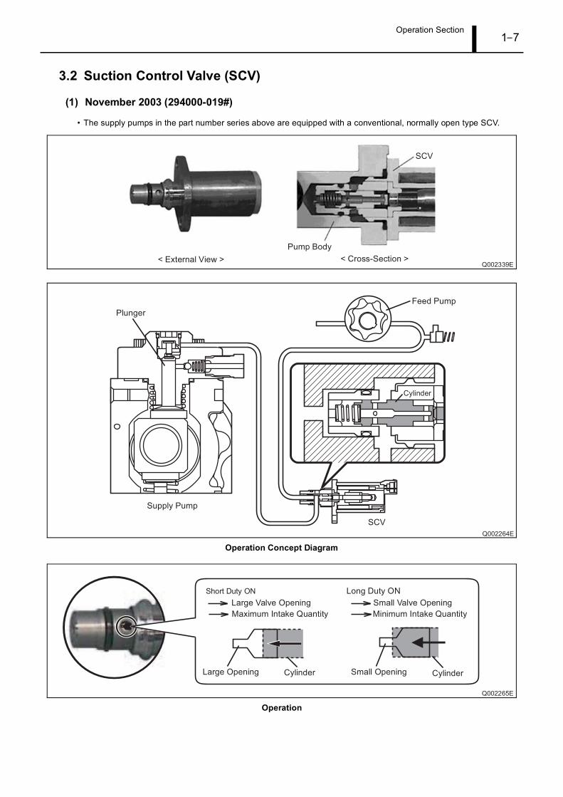
3.2 Suction Control Valve (SCV)
(1) November 2003 (294000-019#)
• The supply pumps in the part number series above are equipped with a conventional, normally open type SCV.
Operation Concept Diagram
Operation
Operation Section1–8
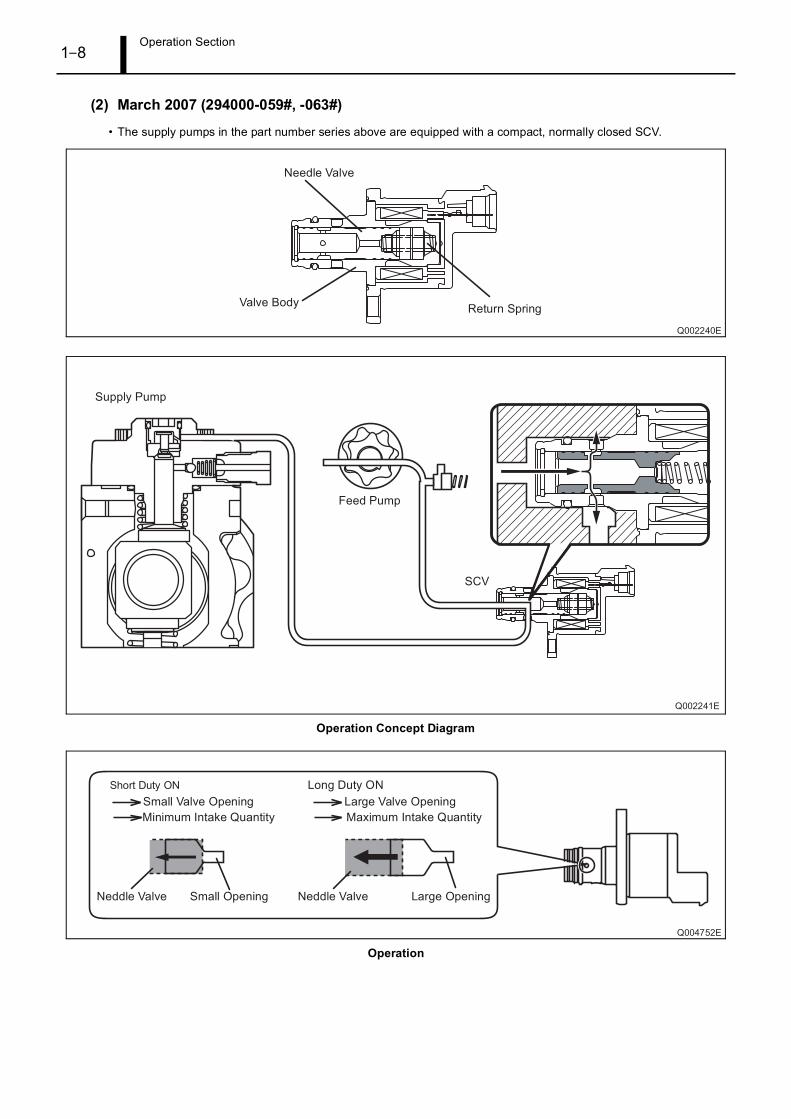
(2) March 2007 (294000-059#, -063#)
• The supply pumps in the part number series above are equipped with a compact, normally closed SCV.
Operation Concept Diagram
Operation

Operation Section1–9
(3) March 2007 (294000-063#*) and November 2009 (294000-059#)
• The supply pumps in the part number series above are equipped with a conventional, normally closed
type SCV
* : Beginning from October 2007
Operation Concept Diagram
Operation

Operation Section1–10
3.3 Fuel Temperature Sensor
A conventional sensor is used with the NO4C-# engine CRS. Sensor resistance values in relation to fuel
temperature are provided below.

Operation Section1–11
4. RAIL
4.1 Outline
Rails in the part number series 095440-049# have a flow damper to suppress fuel pulsations.
Since rails in the part number series 095440-098# have a built-in function to suppress fuel pulsations, there
is no flow damper.
(1) November 2003 (Rail: 095440-049#)
(2) March 2007, and June 2009 (Rail: 095440-098#)

Operation Section1–12
5. INJECTOR
5.1 Outline
The CRS detailed herein uses solenoid injectors with QR codes.
The injectors used in the June 2009 model CRS were designed to show improved responsiveness, as well
as to increase resistance against foreign material adherence to the nozzle.
(1) November 2003 (Injector: 095000-532#)

Operation Section1–13
(2) March 2007 (Injector: 095000-651#, -652#, -655#)

Operation Section1–14
(3) June 2009 (Injector: 095000-847#, -848#)
Operation Section1–15
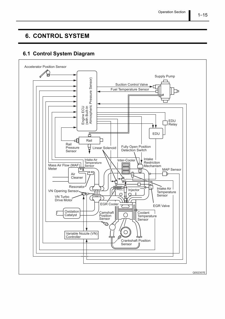
6. CONTROL SYSTEM
6.1 Control System Diagram

Operation Section1–16
6.2 Engine ECU
General export vehicles for Europe, Oceania, and Asia use 12 V specification engine ECUs in relation to
the 24 V vehicle power supply (battery voltage). Accordingly, in the event that service such as repairs are
necessary, always verify the engine ECU specifications. To verify the specifications, look behind the
passenger seat back and check the engine ECU case, as well as whether or not there is a DC-DC converter.
< ATTENTION >When performing checks, do not apply vehicle power supply voltage to the engine ECU. If the
vehicle power supply voltage (24 V) is applied to a 12 V specification engine ECU, the ECU may be
damaged.
The figure below is an external view of the engine ECU. For the connector pin layout and external wiring
diagram: Refer to [Connector Terminal Layout] on P1-57.

Operation Section1–17
6.3 Electronic Drive Unit (EDU)
A conventional EDU is used with the NO4C-# engine CRS.
(1) Operation
• A high-voltage generating device converts the battery voltage into high voltage. The engine ECU sends signals to
terminals B through E of the EDU in accordance with the signals from each sensor. Upon receiving these signals, the
EDU outputs signals to the injectors from terminals K through N. At this time, terminal F outputs the IJf injection
verification signal to the ECU.
External Wiring Diagram

Operation Section1–18
6.4 Sensors
(1) Crankshaft position sensor and camshaft position sensor
• Conventional sensors are used as the crankshaft position sensor and camshaft position sensor. The crankshaft
position sensor is a Magnetic Pick Up (MPU) type sensor, while the camshaft position sensor is a Magnetic
Resistance Element (MRE) type.
Operation Section1–19
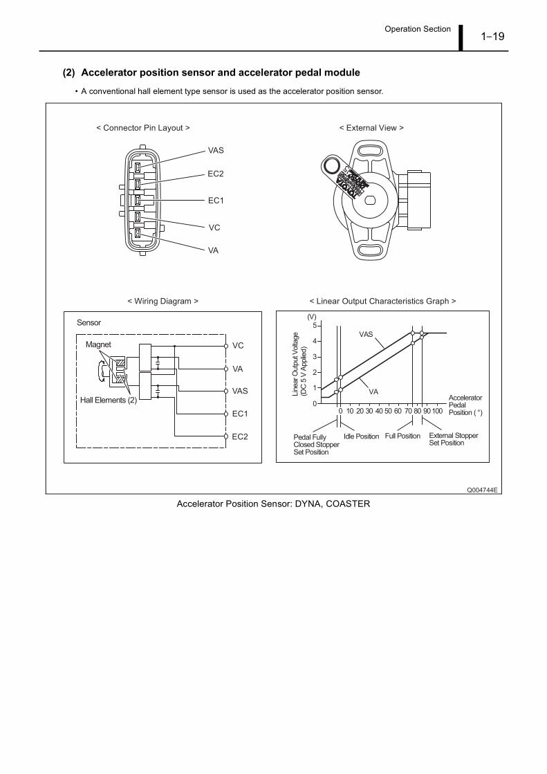
(2) Accelerator position sensor and accelerator pedal module
• A conventional hall element type sensor is used as the accelerator position sensor.
Accelerator Position Sensor: DYNA, COASTER
Operation Section1–20
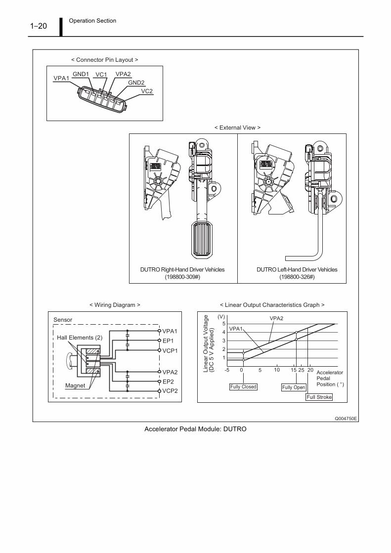
Accelerator Pedal Module: DUTRO
Operation Section1–21
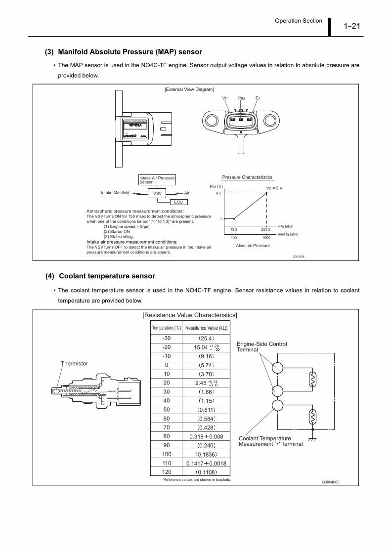
(3) Manifold Absolute Pressure (MAP) sensor
• The MAP sensor is used in the NO4C-TF engine. Sensor output voltage values in relation to absolute pressure are
provided below.
(4) Coolant temperature sensor
• The coolant temperature sensor is used in the NO4C-TF engine. Sensor resistance values in relation to coolant
temperature are provided below.
Operation Section1–22
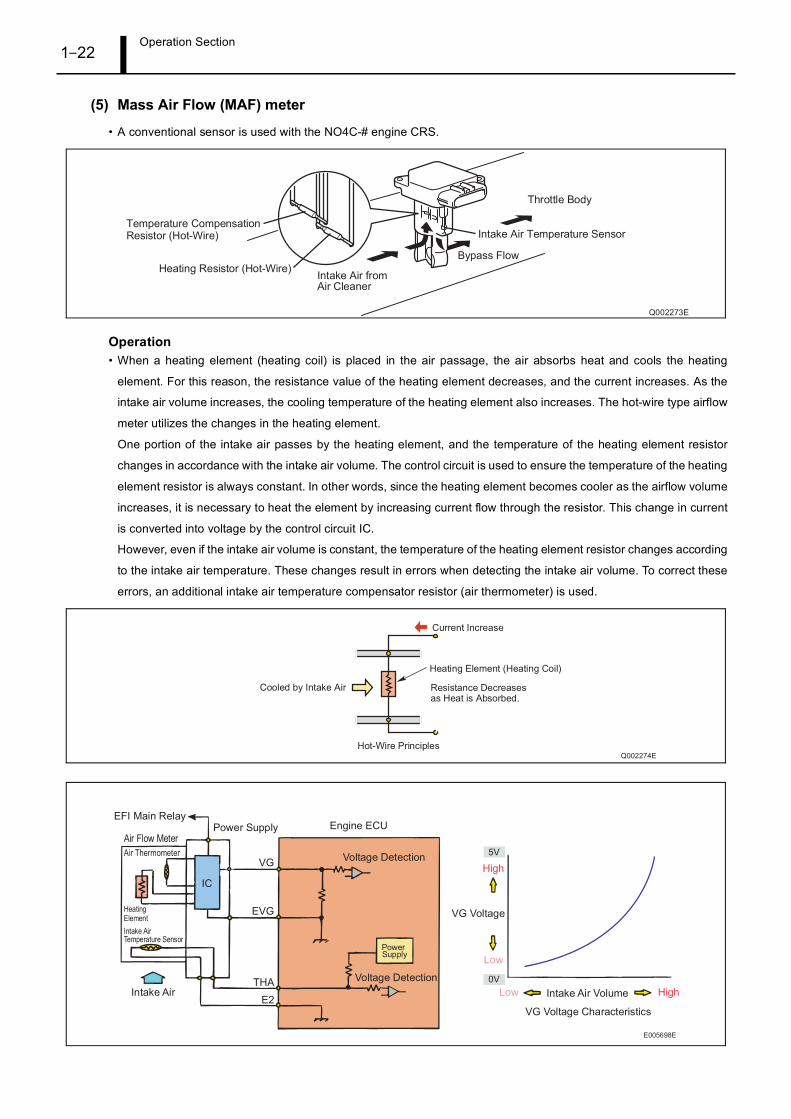
(5) Mass Air Flow (MAF) meter
• A conventional sensor is used with the NO4C-# engine CRS.
Operation• When a heating element (heating coil) is placed in the air passage, the air absorbs heat and cools the heating
element. For this reason, the resistance value of the heating element decreases, and the current increases. As the
intake air volume increases, the cooling temperature of the heating element also increases. The hot-wire type airflow
meter utilizes the changes in the heating element.
One portion of the intake air passes by the heating element, and the temperature of the heating element resistor
changes in accordance with the intake air volume. The control circuit is used to ensure the temperature of the heating
element resistor is always constant. In other words, since the heating element becomes cooler as the airflow volume
increases, it is necessary to heat the element by increasing current flow through the resistor. This change in current
is converted into voltage by the control circuit IC.
However, even if the intake air volume is constant, the temperature of the heating element resistor changes according
to the intake air temperature. These changes result in errors when detecting the intake air volume. To correct these
errors, an additional intake air temperature compensator resistor (air thermometer) is used.

Operation Section1–23
7. EXHAUST GAS CONTROL SYSTEM (FEBRUARY 2007, AND JUNE 2009)
7.1 Outline
Both an Electric-Exhaust Gas Recirculation (E-EGR) and a Diesel Particulate Filter (DPF) system are used
to comply with Euro 4 emission regulations. The EGR valve, exhaust gas temperature sensor, and
differential pressure sensor are made by DENSO.
7.2 E-EGR System
The E-EGR system is an electronically controlled EGR system. The EGR system reduces NOx by lowering
the combustion temperature through re-circulating a portion of the exhaust gas to the intake manifold. Since
this system may also reduce engine output and decrease drivability, the EGR volume is controlled
electronically to an optimum level in accordance with driving conditions.
Both the electronically controlled EGR system and a high-capacity multipass system EGR cooler are used.
Engine performance has been increased through enabling high-volume exhaust gas recirculation.
A linear solenoid type valve is used as the actuator in the EGR valve. Simultaneous PM and NOx reduction
have been achieved by increasing EGR quantity adjustment precision.
An EGR valve lift sensor is also used. The EGR valve opening is fed back to the engine control computer
to enable optimal EGR control.
(1) Construction and operation
• To improve EGR exhaust gas purification performance, feedback control is performed using the EGR valve position.
Oxygen concentration in the intake air (which changes according to EGR) is controlled to a target value in accordance
with the engine state (engine speed, rising pressure, part temperatures, load and intake air volume.)
• To expand the EGR range, the lift sensor installed on the EGR valve performs feedback control of the
actual EGR quantity in relation to the pre-set target EGR quantity. Feedback control is based on the intake
restriction position and the variable nozzle turbo position.
Operation Section1–24
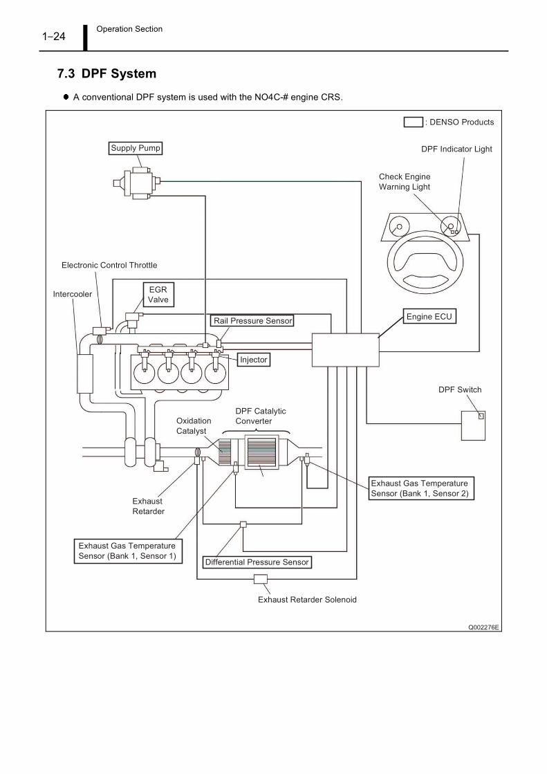
7.3 DPF System
A conventional DPF system is used with the NO4C-# engine CRS.

Operation Section1–25
(1) Exhaust gas temperature sensor
• A conventional sensor is used as the exhaust gas temperature sensor. Sensor resistance values in relation to exhaust
gas temperature are provided below.
(2) Differential pressure sensor
• A conventional sensor is used as the differential pressure sensor. Sensor output voltage values in relation to exhaust
gas differential pressure are provided below.
Operation Section1–26
8. ENGINE ECU DIAGNOSTIC TROUBLE CODES (DTC)
8.1 DTC Table
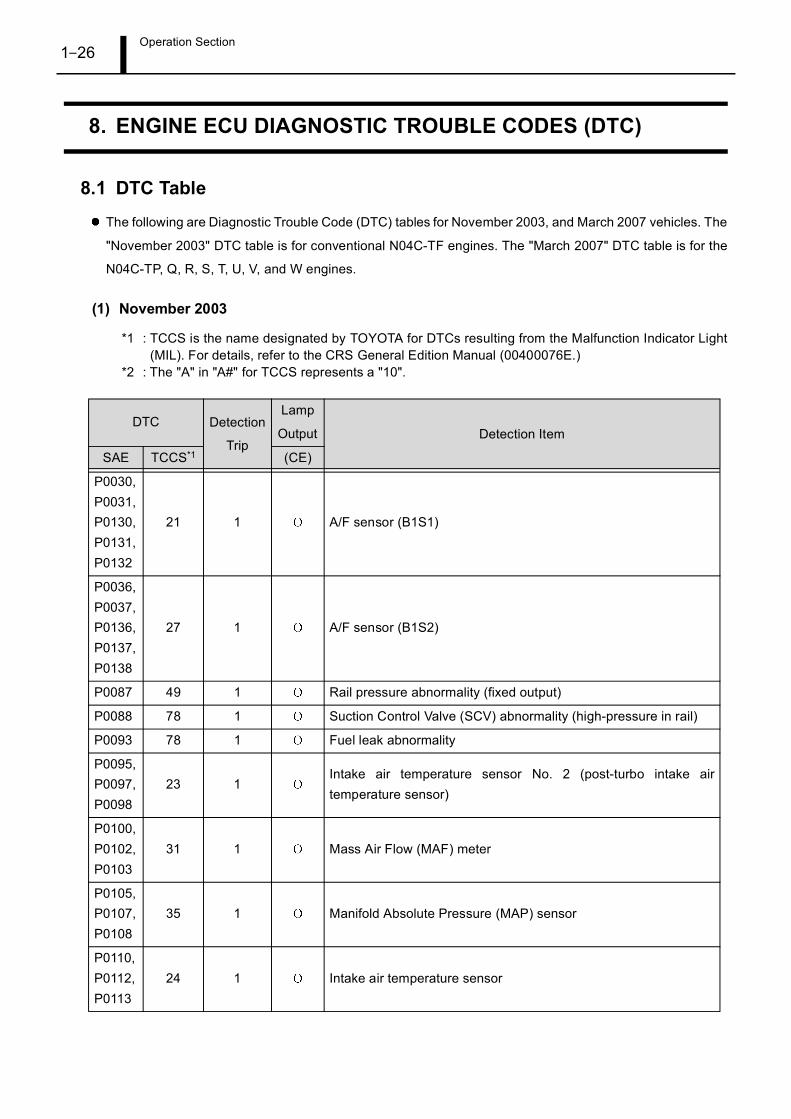
The following are Diagnostic Trouble Code (DTC) tables for November 2003, and March 2007 vehicles. The
"November 2003" DTC table is for conventional N04C-TF engines. The "March 2007" DTC table is for the
N04C-TP, Q, R, S, T, U, V, and W engines.
(1) November 2003
*1 : TCCS is the name designated by TOYOTA for DTCs resulting from the Malfunction Indicator Light(MIL). For details, refer to the CRS General Edition Manual (00400076E.)
*2 : The "A" in "A#" for TCCS represents a "10".
DTC Detection
Trip
Lamp
Output Detection Item
SAE TCCS*1 (CE)
P0030,P0031,P0130,P0131,P0132
21 1 A/F sensor (B1S1)
P0036,P0037,P0136,P0137,P0138
27 1 A/F sensor (B1S2)
P0087 49 1 Rail pressure abnormality (fixed output)
P0088 78 1 Suction Control Valve (SCV) abnormality (high-pressure in rail)
P0093 78 1 Fuel leak abnormality
P0095,P0097,P0098
23 1Intake air temperature sensor No. 2 (post-turbo intake airtemperature sensor)
P0100,P0102,P0103
31 1 Mass Air Flow (MAF) meter
P0105,P0107,P0108
35 1 Manifold Absolute Pressure (MAP) sensor
P0110,P0112,P0113
24 1 Intake air temperature sensor

Operation Section1–27
P0115,P0117,P0118
22 1 Coolant temperature sensor
P0120,P0122,P0123
41 1 Accelerator position sensor
P0168 39 1 Abnormally high fuel temperature
P0180,P0182,P0183
39 1 Fuel temperature sensor
P0190,P0192,P0193
49 1 Rail pressure sensor with back-up sensor
P0191 49 1 Rail pressure sensor with back-up sensor (out- of-range)
P0200 97 1 EDU abnormality (engine diagnostic)
P0234 34 1 VN turbo abnormality (closed-side abnormality)
P0263 78 1 Injector abnormality (FCCB abnormality) (No. 1 cylinder)
P0266 78 1 Injector abnormality (FCCB abnormality) (No. 2 cylinder)
P0269 78 1 Injector abnormality (FCCB abnormality) (No. 3 cylinder)
P0272 78 1 Injector abnormality (FCCB abnormality) (No. 4 cylinder)
P0299 34 1 VN turbo abnormality (open-side abnormality)
P033513 1
Crankshaft position sensor (open circuit/phase difference/powerflicker)
P0335 12 1 Crankshaft position sensor (open circuit)
P0339 13 1 Crankshaft position sensor (NE power flicker)
P0340 12 1 Crankshaft position sensor (open circuit/power flicker)
P0340 12 1 Camshaft position sensor (during start-up)
P0400 71 1 Exhaust Gas Recirculation (EGR) flow malfunction
P0400 71 1 EGR valve
P0405,P0406
96 1 EGR lift sensor
P0488 15 1 Intake restriction motor control system
P0500 42 1 Vehicle speed sensor (MT)
P0504 51 1 Stop light switch
P0607 89 1 CPU abnormality
P0627 78 1 Pump abnormality (open/short circuit)
P1133 00 1 Exterior accelerator position No. 1 sensor high
P1143 19 1 Throttle knob high
DTC Detection
Trip
Lamp
Output Detection Item
SAE TCCS*1 (CE)
Operation Section1–28
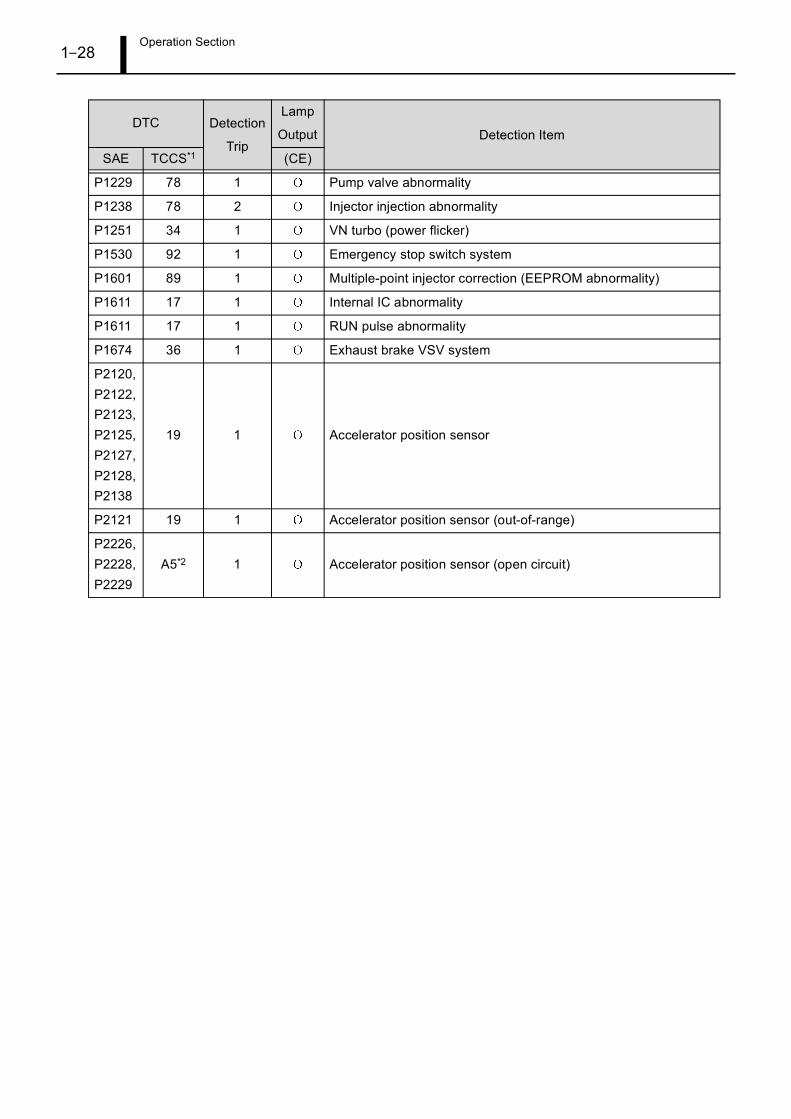
P1229 78 1 Pump valve abnormality
P1238 78 2 Injector injection abnormality
P1251 34 1 VN turbo (power flicker)
P1530 92 1 Emergency stop switch system
P1601 89 1 Multiple-point injector correction (EEPROM abnormality)
P1611 17 1 Internal IC abnormality
P1611 17 1 RUN pulse abnormality
P1674 36 1 Exhaust brake VSV system
P2120,P2122,P2123,P2125,P2127,P2128,P2138
19 1 Accelerator position sensor
P2121 19 1 Accelerator position sensor (out-of-range)
P2226,P2228,P2229
A5*2 1 Accelerator position sensor (open circuit)
DTC Detection
Trip
Lamp
Output Detection Item
SAE TCCS*1 (CE)
Operation Section1–29
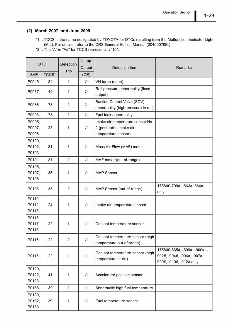
(2) March 2007, and June 2009
*1 : TCCS is the name designated by TOYOTA for DTCs resulting from the Malfunction Indicator Light(MIL). For details, refer to the CRS General Edition Manual (00400076E.)
*2 : The "A" in "A#" for TCCS represents a "10".
DTC Detection
Trip
Lamp
Output Detection Item Remarks
SAE TCCS*1 (CE)
P0045 34 1 VN turbo (open)
P0087 49 1Rail pressure abnormality (fixed output)
P0088 78 1Suction Control Valve (SCV) abnormality (high-pressure in rail)
P0093 78 1 Fuel leak abnormality
P0095,P0097,P0098
23 1Intake air temperature sensor No. 2 (post-turbo intake air temperature sensor)
P0100,P0102,P0103
31 1 Mass Air Flow (MAF) meter
P0101 31 2 MAF meter (out-of-range)
P0105,P0107,P0108
35 1 MAP Sensor
P0106 35 2 MAP Sensor (out-of-range)175800-799#, -863#, 864# only
P0110,P0112,P0113
24 1 Intake air temperature sensor
P0115,P0117,P0118
22 1 Coolant temperature sensor
P0116 22 2Coolant temperature sensor (hightemperature out-of-range)
P0116 22 1Coolant temperature sensor (hightemperature stuck)
175800-865#, -899#, -900#, -902#, -904#, -906#, -907#, -909#, -910#, -912# only
P0120,P0122,P0123
41 1 Accelerator position sensor
P0168 39 1 Abnormally high fuel temperature
P0180,P0182,P0183
39 1 Fuel temperature sensor

Operation Section1–30
P0190,P0192,P0193
49 1Rail pressure sensor with back-up sensor
P0191 49 1Rail pressure sensor with back-up sensor (out- of-range)
175800-799#, -863#, 864# only
P0200 97 1EDU abnormality (engine diagnostic)
P0234 34 1VN turbo abnormality (closed-side abnormality)
P0263 78 1Injector abnormality (FCCBabnormality) (No. 1 cylinder)
P0266 78 1Injector abnormality (FCCBabnormality) (No. 2 cylinder)
P0269 78 1Injector abnormality (FCCBabnormality) (No. 3 cylinder)
P0272 78 1Injector abnormality (FCCBabnormality) (No. 4 cylinder)
P0299 34 1VN turbo abnormality (open-sideabnormality)
P0335 13 1Crankshaft position sensor (opencircuit/phase difference/powerflicker)
P0335 12 1Crankshaft position sensor (opencircuit)
P0339 13 1Crankshaft position sensor (NEpower flicker)
P0340 12 1Crankshaft position sensor (opencircuit/power flicker)
P0340 12 1Camshaft position sensor (duringstart-up)
P0400 71 2 EGR flow malfunction
P0400 71 1 EGR system malfunction
P0405,P0406
96 1 EGR lift sensor
P0405,P0406
96 1 EGR lift sensor
P0488 15 1Intake restriction motor controlsystem
P0500 42 2 Vehicle speed sensor (MT)
P0504 51 1 Stop light switch
DTC Detection
Trip
Lamp
Output Detection Item Remarks
SAE TCCS*1 (CE)

Operation Section1–31
P0544,P0545,P0546
A3*2 1Exhaust temperature sensorcircuit malfunction (in)
P0607 89 1 CPU abnormality
P0617 43 1 Starter abnormally high
P0627 78 1Fuel pump abnormality (Open/ short circuit)
P0630 89 1Vehicle Identification Number(VIN) not read
P0863 17 1 EFI ECT communication fault175800-865#, -899#, -900#, -902#, -904#, -906#, -907#, -909#, -910#, -912# only
P1133 00 1Exterior accelerator positionsensor high
P1143 19 1 Throttle knob high
P1229 78 1Fuel pump abnormality (open/short circuit)
P1238 78 2 Injector injection abnormality
P1251 34 1 VN turbo (power flicker)
P1425,P1427,P1428
A4*2 1Differential pressure sensor (opencircuit)
P1426 A4*2 1Differential pressure sensor(incorrect piping)
P1530 92 1 Emergency stop switch system
P1601 89 1Multiple-point injector correction(EEPROM abnormality)
P1611 17 1 Internal IC abnormality
P1611 17 1 RUN pulse abnormality
P1674 36 1 Exhaust brake VSV system
P2002 94 1 DPF system abnormality
P2031,P2032,P2033
A3*2 1 Exhaust temperature sensor (out)
P2120,P2122,P2123,P2125,P2127,P2128,P2138
19 1 Accelerator position sensor
DTC Detection
Trip
Lamp
Output Detection Item Remarks
SAE TCCS*1 (CE)

Operation Section1–32
P2121 19 1Accelerator position sensor (out-of-range)
P2226,P2228,P2229
A5*2 1Atmospheric pressure sensor(open circuit)
P2227 A5*2 2Atmospheric pressure sensor(out-of-range)
U0293 A2*2 1CAN communication (HV ECU:communication disruption) 175800-865#, -899#, -900#, -
902#, -904#, -906#, -907#, -909#, -910#, -912# onlyU1123 A2*2 1
VNT ECU CAN communication(reception abnormality)
DTC Detection
Trip
Lamp
Output Detection Item Remarks
SAE TCCS*1 (CE)
Operation Section1–33
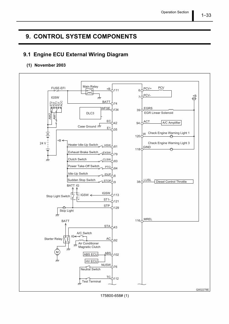
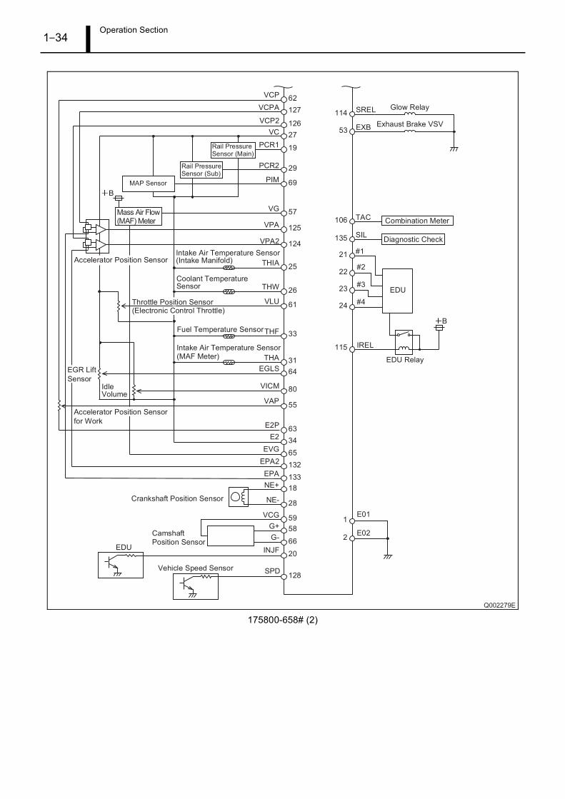
9. CONTROL SYSTEM COMPONENTS
9.1 Engine ECU External Wiring Diagram
(1) November 2003
175800-658# (1)
Operation Section1–34
175800-658# (2)

Operation Section1–35
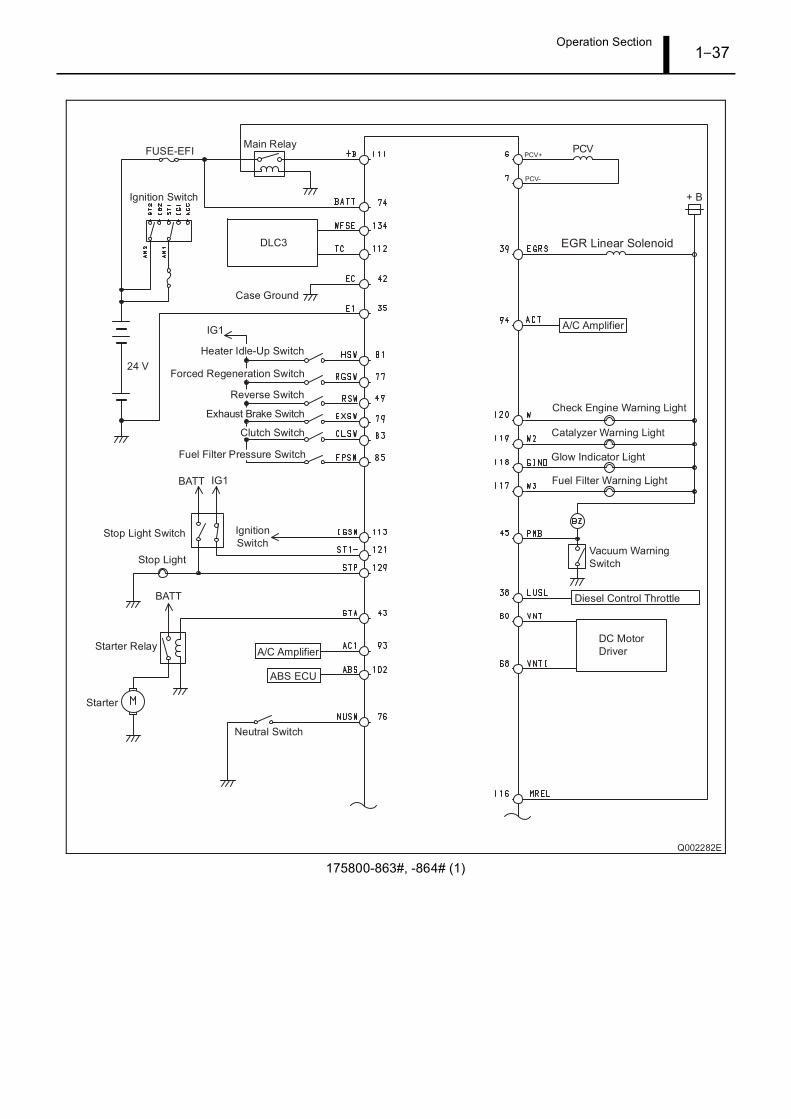
(2) March 2007
175800-799# (1)

Operation Section1–36
175800-799# (2)
Operation Section1–37
175800-863#, -864# (1)

Operation Section1–38
175800-863#, -864# (2)

Operation Section1–39
175800-865# (1)

Operation Section1–40
175800-865# (2)
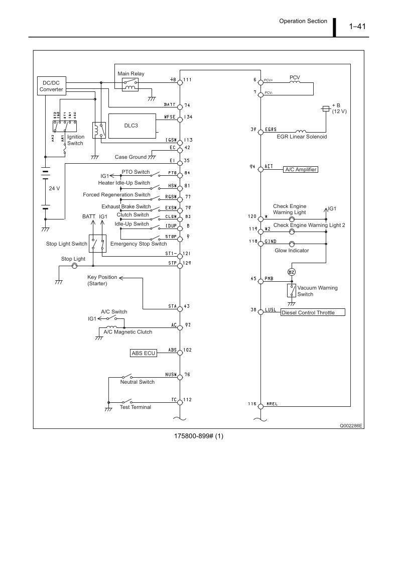
Operation Section1–41
175800-899# (1)

Operation Section1–42
175800-899# (2)

Operation Section1–43
175800-900#, -902#, -907#, -909# (1)

Operation Section1–44
175800-900#, -902#, -907#, -909# (2)

Operation Section1–45
175800-904#, -910# (1)

Operation Section1–46
175800-904#, -910# (2)

Operation Section1–47
175800-906#, -912# (1)

Operation Section1–48
175800-906#, -912# (2)

Operation Section1–49
(3) June 2009
275900-087# (1)

Operation Section1–50
275900-087# (2)

Operation Section1–51
275900-089# (1)

Operation Section1–52
275900-089# (2)

Operation Section1–53
275900-090# (1)
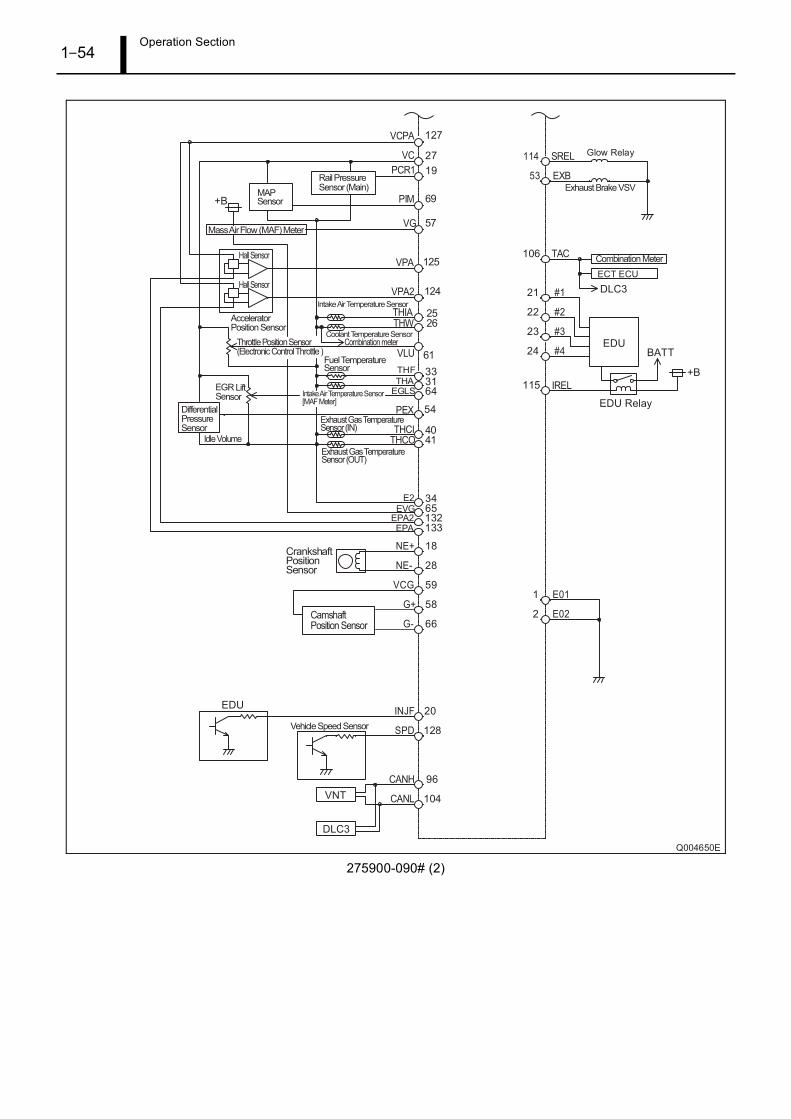
Operation Section1–54
275900-090# (2)

Operation Section1–55
275900-136# (1)

Operation Section1–56
275900-136# (2)

Operation Section1–57
9.2 Connector Terminal Layout
(1) November 2003
175800-658#
(2) March 2007
175800-799#
175800-863#, -864#

Operation Section1–58
175800-865#
175800-899#
175800-900#, -902#, -907#, -909#
175800-904#, -910#

Operation Section1–59
175800-906#, -912#
(3) June 2009
275900-087#
275900-089#
275900-090#

Operation Section1–60
275900-136#

Service Department DENSO CORPORATION1-1, Showa-cho, Kariya-shi, Aichi-ken, 448-8661, Japan