N series - Farnell element14 · R161 220 000 (page 19) 11/75/D (RG 216) R162 088 000 (page 44) R162...
99
ISO 9001 APPROVED STANDARD COAXIAL CONNECTORS N series
-
Upload
nguyendang -
Category
Documents
-
view
218 -
download
0
Transcript of N series - Farnell element14 · R161 220 000 (page 19) 11/75/D (RG 216) R162 088 000 (page 44) R162...

ISO 9001 APPROVED
STANDARD COAXIAL CONNECTORS
N series
CONTENTSN
3
N Page
RADIALL company profile 4--5. . . . . . . . . . . . . . . . . . . . . . . . . . . . . . . . . . . . . . . . . . . . . . . . . . . . . . . . . . . .N series introduction 6--7. . . . . . . . . . . . . . . . . . . . . . . . . . . . . . . . . . . . . . . . . . . . . . . . . . . . . . . . . . . . . . . .General 8. . . . . . . . . . . . . . . . . . . . . . . . . . . . . . . . . . . . . . . . . . . . . . . . . . . . . . . . . . . . . . . . . . . . . . . . . . . . .Finder guide 9--11. . . . . . . . . . . . . . . . . . . . . . . . . . . . . . . . . . . . . . . . . . . . . . . . . . . . . . . . . . . . . . . . . . . . . . .
N 50Interface 12. . . . . . . . . . . . . . . . . . . . . . . . . . . . . . . . . . . . . . . . . . . . . . . . . . . . . . . . . . . . . . . . . . . . . . . . . . . .Characteristics 13--14. . . . . . . . . . . . . . . . . . . . . . . . . . . . . . . . . . . . . . . . . . . . . . . . . . . . . . . . . . . . . . . . . . .Straight plugs 15--16. . . . . . . . . . . . . . . . . . . . . . . . . . . . . . . . . . . . . . . . . . . . . . . . . . . . . . . . . . . . . . . . . . . .Right--angle plugs 17--18. . . . . . . . . . . . . . . . . . . . . . . . . . . . . . . . . . . . . . . . . . . . . . . . . . . . . . . . . . . . . . . . .Straight jacks 18--20. . . . . . . . . . . . . . . . . . . . . . . . . . . . . . . . . . . . . . . . . . . . . . . . . . . . . . . . . . . . . . . . . . . . .Flange mount, straight jacks 20--22. . . . . . . . . . . . . . . . . . . . . . . . . . . . . . . . . . . . . . . . . . . . . . . . . . . . . . . .Bulkhead mount, straight jacks 22--24. . . . . . . . . . . . . . . . . . . . . . . . . . . . . . . . . . . . . . . . . . . . . . . . . . . . . .Heads and tips for COAXI--KIT 25--26. . . . . . . . . . . . . . . . . . . . . . . . . . . . . . . . . . . . . . . . . . . . . . . . . . . . . .Flange mount, receptacles 27--29. . . . . . . . . . . . . . . . . . . . . . . . . . . . . . . . . . . . . . . . . . . . . . . . . . . . . . . . . .Bulkhead mount, receptacles 29. . . . . . . . . . . . . . . . . . . . . . . . . . . . . . . . . . . . . . . . . . . . . . . . . . . . . . . . . .In series adapters 30. . . . . . . . . . . . . . . . . . . . . . . . . . . . . . . . . . . . . . . . . . . . . . . . . . . . . . . . . . . . . . . . . . . .Caps 31. . . . . . . . . . . . . . . . . . . . . . . . . . . . . . . . . . . . . . . . . . . . . . . . . . . . . . . . . . . . . . . . . . . . . . . . . . . . . . .Accessories 32--33. . . . . . . . . . . . . . . . . . . . . . . . . . . . . . . . . . . . . . . . . . . . . . . . . . . . . . . . . . . . . . . . . . . . . .Cable assemblies 35--41. . . . . . . . . . . . . . . . . . . . . . . . . . . . . . . . . . . . . . . . . . . . . . . . . . . . . . . . . . . . . . . . .
N 75Interface 42. . . . . . . . . . . . . . . . . . . . . . . . . . . . . . . . . . . . . . . . . . . . . . . . . . . . . . . . . . . . . . . . . . . . . . . . . . . .Characteristics 43. . . . . . . . . . . . . . . . . . . . . . . . . . . . . . . . . . . . . . . . . . . . . . . . . . . . . . . . . . . . . . . . . . . . . .Straight plugs 44. . . . . . . . . . . . . . . . . . . . . . . . . . . . . . . . . . . . . . . . . . . . . . . . . . . . . . . . . . . . . . . . . . . . . . .Right--angle plugs 44--45. . . . . . . . . . . . . . . . . . . . . . . . . . . . . . . . . . . . . . . . . . . . . . . . . . . . . . . . . . . . . . . . .Straight jacks 45. . . . . . . . . . . . . . . . . . . . . . . . . . . . . . . . . . . . . . . . . . . . . . . . . . . . . . . . . . . . . . . . . . . . . . . .Flange mount, straight jacks 46. . . . . . . . . . . . . . . . . . . . . . . . . . . . . . . . . . . . . . . . . . . . . . . . . . . . . . . . . . .Bulkhead mount, straight jacks 46. . . . . . . . . . . . . . . . . . . . . . . . . . . . . . . . . . . . . . . . . . . . . . . . . . . . . . . . .Receptacles 47. . . . . . . . . . . . . . . . . . . . . . . . . . . . . . . . . . . . . . . . . . . . . . . . . . . . . . . . . . . . . . . . . . . . . . . . .In series adapters 47. . . . . . . . . . . . . . . . . . . . . . . . . . . . . . . . . . . . . . . . . . . . . . . . . . . . . . . . . . . . . . . . . . . .
COAXIAL BETWEEN SERIES ADAPTERS 48. . . . . . . . . . . . . . . . . . . . . . . . . . . . . . . . . . . . . . . . . . . . . .
TOOLING 49. . . . . . . . . . . . . . . . . . . . . . . . . . . . . . . . . . . . . . . . . . . . . . . . . . . . . . . . . . . . . . . . . . . . . . . . . . .Kits for flexible cables 50--52. . . . . . . . . . . . . . . . . . . . . . . . . . . . . . . . . . . . . . . . . . . . . . . . . . . . . . . . . . . . . .Kits for semi-rigid cables 53--57. . . . . . . . . . . . . . . . . . . . . . . . . . . . . . . . . . . . . . . . . . . . . . . . . . . . . . . . . . .Limited torque wrench 58. . . . . . . . . . . . . . . . . . . . . . . . . . . . . . . . . . . . . . . . . . . . . . . . . . . . . . . . . . . . . . . .
PANEL DRILLINGS 61--62. . . . . . . . . . . . . . . . . . . . . . . . . . . . . . . . . . . . . . . . . . . . . . . . . . . . . . . . . . . . . . .
ASSEMBLY INSTRUCTIONS 63--94. . . . . . . . . . . . . . . . . . . . . . . . . . . . . . . . . . . . . . . . . . . . . . . . . . . . . .
DIMENSIONS OF APPLICABLE CABLES 95. . . . . . . . . . . . . . . . . . . . . . . . . . . . . . . . . . . . . . . . . . . . . . .
CROSS REFERENCES 96--97. . . . . . . . . . . . . . . . . . . . . . . . . . . . . . . . . . . . . . . . . . . . . . . . . . . . . . . . . . .
INDEX OF RADIALL PART NUMBERS with description 98--102. . . . . . . . . . . . . . . . . . . . . . . . . . . . . . . .
INTRODUCTION
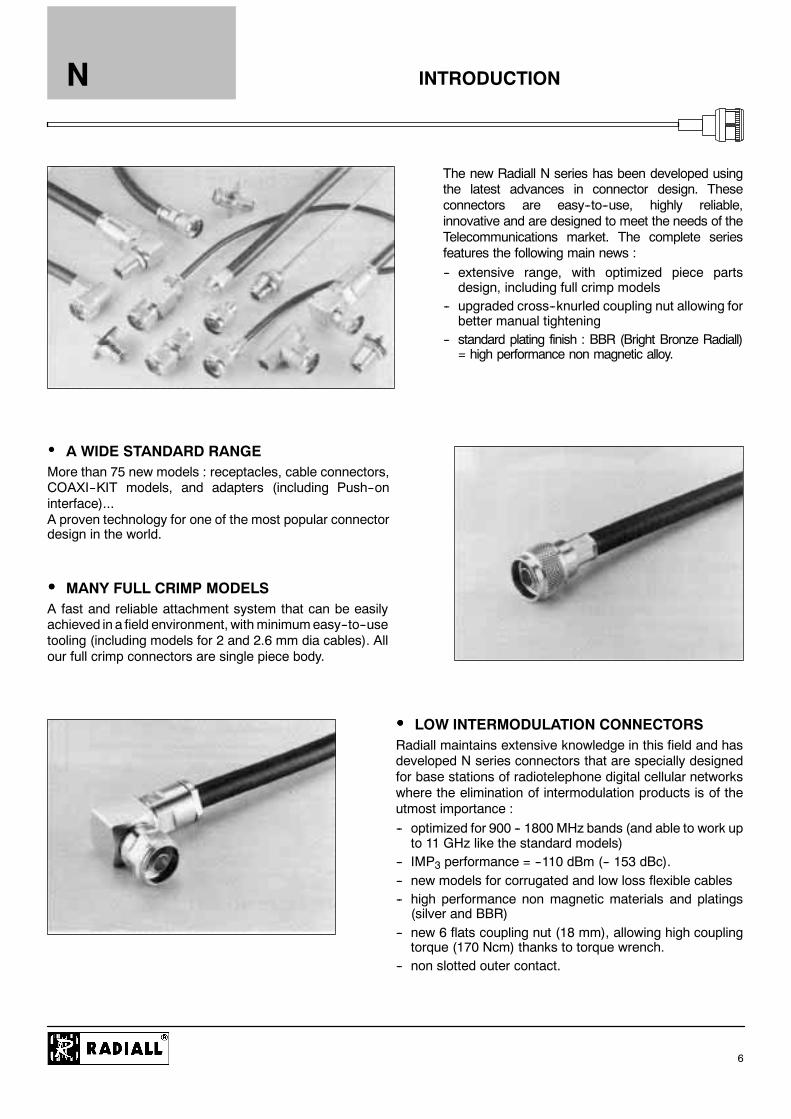
The new Radiall N series has been developed usingthe latest advances in connector design. Theseconnectors are easy--to--use, highly reliable,innovative and are designed to meet the needs of theTelecommunications market. The complete seriesfeatures the following main news :-- extensive range, with optimized piece partsdesign, including full crimp models
-- upgraded cross--knurled coupling nut allowing forbetter manual tightening
-- standard plating finish : BBR (Bright Bronze Radiall)= high performance non magnetic alloy.
A WIDE STANDARD RANGEMore than 75 new models : receptacles, cable connectors,COAXI--KIT models, and adapters (including Push--oninterface)...A proven technology for one of the most popular connectordesign in the world.
MANY FULL CRIMP MODELSA fast and reliable attachment system that can be easilyachieved in a field environment, withminimumeasy--to--usetooling (including models for 2 and 2.6 mm dia cables). Allour full crimp connectors are single piece body.
LOW INTERMODULATION CONNECTORSRadiall maintains extensive knowledge in this field and hasdeveloped N series connectors that are specially designedfor base stations of radiotelephone digital cellular networkswhere the elimination of intermodulation products is of theutmost importance :-- optimized for 900 -- 1800MHz bands (and able to work upto 11 GHz like the standard models)
-- IMP3 performance = --110 dBm (-- 153 dBc).-- new models for corrugated and low loss flexible cables-- high performance non magnetic materials and platings(silver and BBR)
-- new 6 flats coupling nut (18 mm), allowing high couplingtorque (170 Ncm) thanks to torque wrench.
-- non slotted outer contact.
N
6
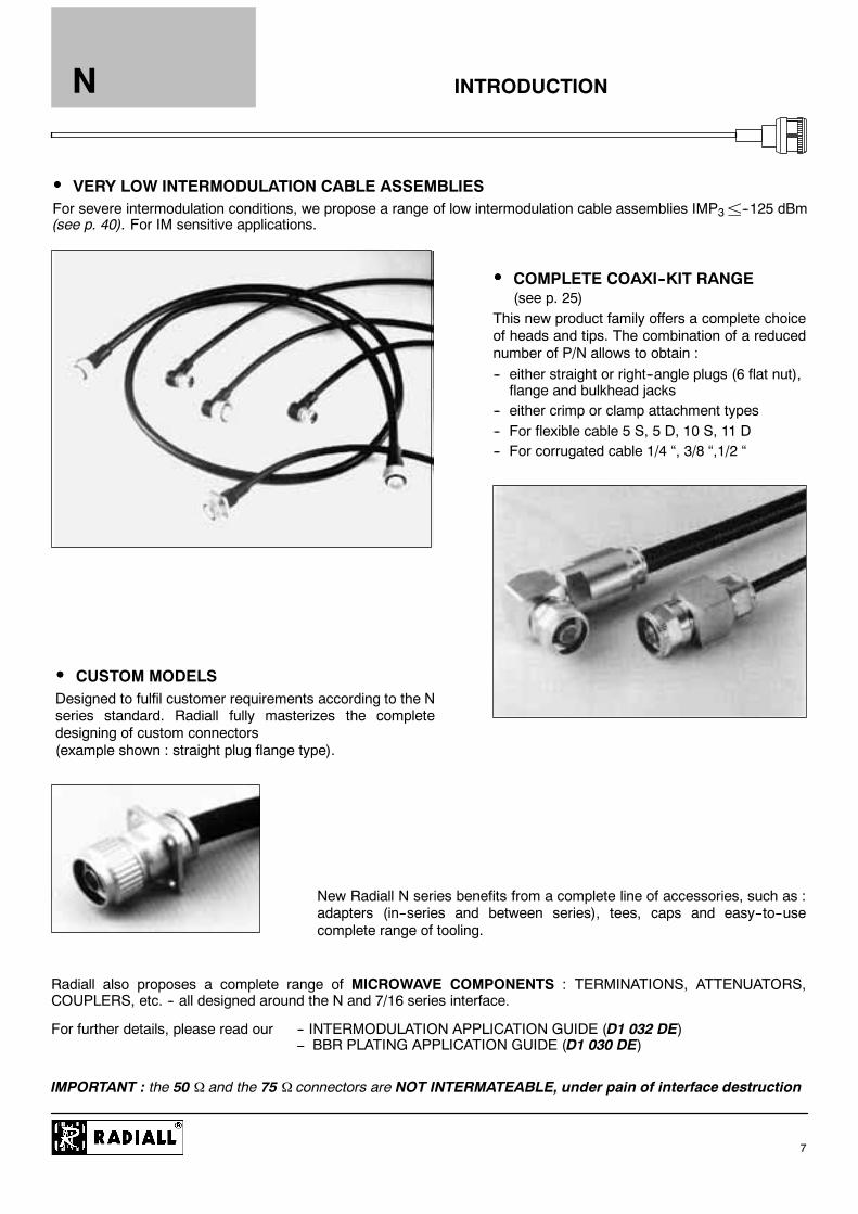
COMPLETE COAXI--KIT RANGE(see p. 25)
This new product family offers a complete choiceof heads and tips. The combination of a reducednumber of P/N allows to obtain :-- either straight or right--angle plugs (6 flat nut),flange and bulkhead jacks
-- either crimp or clamp attachment types-- For flexible cable 5 S, 5 D, 10 S, 11 D-- For corrugated cable 1/4 “, 3/8 “,1/2 “
INTRODUCTION
VERY LOW INTERMODULATION CABLE ASSEMBLIESFor severe intermodulation conditions, we propose a range of low intermodulation cable assemblies IMP3±--125 dBm(see p. 40). For IM sensitive applications.
CUSTOM MODELSDesigned to fulfil customer requirements according to the Nseries standard. Radiall fully masterizes the completedesigning of custom connectors(example shown : straight plug flange type).
New Radiall N series benefits from a complete line of accessories, such as :adapters (in--series and between series), tees, caps and easy--to--usecomplete range of tooling.
Radiall also proposes a complete range of MICROWAVE COMPONENTS : TERMINATIONS, ATTENUATORS,COUPLERS, etc. -- all designed around the N and 7/16 series interface.
For further details, please read our -- INTERMODULATION APPLICATION GUIDE (D1 032 DE)BBR PLATING APPLICATION GUIDE (D1 030 DE)
IMPORTANT : the 50 and the 75 connectors are NOT INTERMATEABLE, under pain of interface destruction
N
7

50
75
GENERAL
D Standard coaxial connectorsD Screw--on couplingD High durability and proven strengthD High power ratingD Excellent RF performanceD 2 ranges : N 50
N 75
APPLICABLE STANDARDS
D MIL-C-39012 / MIL STD 348-304D CEI 169-16D CECC 22210D NF-C-93566
APPLICATIONS
D Wireless communicationsD Civil and military radio--telecommunication
equipmentD CountermeasureD Navy equipmentD VideocommunicationD Computer networkD Industrial network
DC - 11 GHz
DC - 1.5 GHz
GENERALN
8
FINDER GUIDEN
9
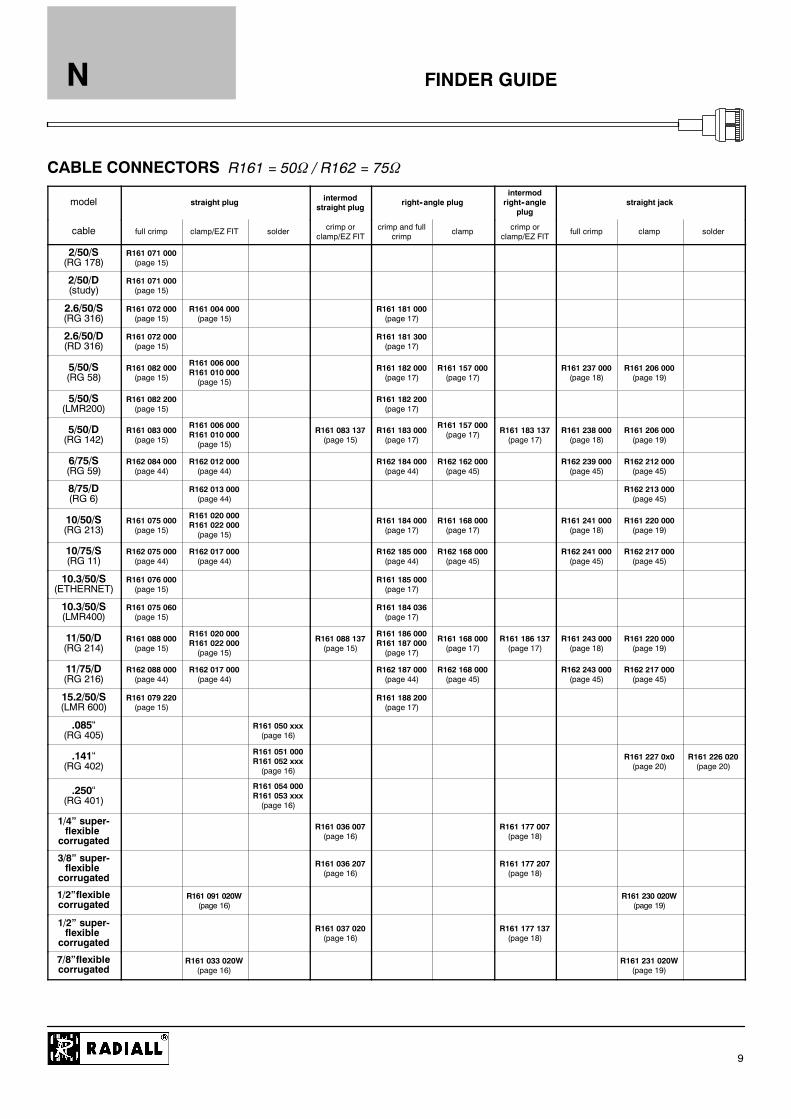
CABLE CONNECTORS R161 = 50 / R162 = 75
model straight plug intermodstraight plug
right--angle plugintermodright--angle
plugstraight jack
cable full crimp clamp/EZ FIT solder crimp orclamp/EZ FIT
crimp and fullcrimp
clamp crimp orclamp/EZ FIT
full crimp clamp solder
2/50/S(RG 178)
R161 071 000(page 15)
2/50/D(study)
R161 071 000(page 15)
2.6/50/S(RG 316)
R161 072 000(page 15)
R161 004 000(page 15)
R161 181 000(page 17)
2.6/50/D(RD 316)
R161 072 000(page 15)
R161 181 300(page 17)
5/50/S(RG 58)
R161 082 000(page 15)
R161 006 000R161 010 000(page 15)
R161 182 000(page 17)
R161 157 000(page 17)
R161 237 000(page 18)
R161 206 000(page 19)
5/50/S(LMR200)
R161 082 200(page 15)
R161 182 200(page 17)
5/50/D(RG 142)
R161 083 000(page 15)
R161 006 000R161 010 000(page 15)
R161 083 137(page 15)
R161 183 000(page 17)
R161 157 000(page 17) R161 183 137
(page 17)R161 238 000(page 18)
R161 206 000(page 19)
6/75/S(RG 59)
R162 084 000(page 44)
R162 012 000(page 44)
R162 184 000(page 44)
R162 162 000(page 45)
R162 239 000(page 45)
R162 212 000(page 45)
8/75/D(RG 6)
R162 013 000(page 44)
R162 213 000(page 45)
10/50/S(RG 213)
R161 075 000(page 15)
R161 020 000R161 022 000(page 15)
R161 184 000(page 17)
R161 168 000(page 17)
R161 241 000(page 18)
R161 220 000(page 19)
10/75/S(RG 11)
R162 075 000(page 44)
R162 017 000(page 44)
R162 185 000(page 44)
R162 168 000(page 45)
R162 241 000(page 45)
R162 217 000(page 45)
10.3/50/S(ETHERNET)
R161 076 000(page 15)
R161 185 000(page 17)
10.3/50/S(LMR400)
R161 075 060(page 15)
R161 184 036(page 17)
11/50/D(RG 214)
R161 088 000(page 15)
R161 020 000R161 022 000(page 15)
R161 088 137(page 15)
R161 186 000R161 187 000(page 17)
R161 168 000(page 17)
R161 186 137(page 17)
R161 243 000(page 18)
R161 220 000(page 19)
11/75/D(RG 216)
R162 088 000(page 44)
R162 017 000(page 44)
R162 187 000(page 44)
R162 168 000(page 45)
R162 243 000(page 45)
R162 217 000(page 45)
15.2/50/S(LMR 600)
R161 079 220(page 15)
R161 188 200(page 17)
.085“(RG 405)
R161 050 xxx(page 16)
.141“(RG 402)
R161 051 000R161 052 xxx(page 16)
R161 227 0x0(page 20)
R161 226 020(page 20)
.250“(RG 401)
R161 054 000R161 053 xxx(page 16)
1/4” super-flexible
corrugatedR161 036 007(page 16)
R161 177 007(page 18)
3/8” super-flexible
corrugatedR161 036 207(page 16)
R161 177 207(page 18)
1/2”flexiblecorrugated
R161 091 020W(page 16)
R161 230 020W(page 19)
1/2” super-flexible
corrugatedR161 037 020(page 16)
R161 177 137(page 18)
7/8”flexiblecorrugated
R161 033 020W(page 16)
R161 231 020W(page 19)

FINDER GUIDEN
10
CABLE CONNECTORS R161 = 50 / R162 = 75
model intermodstraight jack square flange straight jack
intermodsquare flangestraight jack
bulkhead straight jack (panel sealed)intermod bulk-head straight
jack
cable clamp/EZ FIT full crimp clamp solder clamp/EZ FIT full crimp clamp solder clamp/EZ FIT
2/50/S(RG 178)
R161 281 000(page 20)
R161 309 x00(page 22)
2/50/D(study)
R161 281 000(page 20)
R161 309 x00(page 22)
2.6/50/S(RG 316)
R161 281 300(page 20)
R161 252 000(page 21)
R161 311 x00(page 22)
R161 321 000R161 322 000(page 23)
2.6/50/D(RD 316)
R161 281 300(page 20)
R161 252 000(page 21)
R161 311 x00(page 22)
R161 321 000R161 322 000(page 23)
5/50/S(RG 58)
R161 282 000(page 20)
R161 256 000(page 21)
R161 329 000(page 22)
R161 325 000(page 23)
5/50/S(LMR200)
R161 329 130(page 22)
5/50/D(RG 142)
R161 283 000(page 20)
R161 256 000(page 21)
R161 329 200(page 22)
R161 325 000(page 23)
6/75/S(RG 59)
R162 262 000(page 46)
R162 335 000(page 46)
R162 328 000(page 46)
10/50/S(RG 213)
R161 286 000(page 20)
R161 270 000(page 21)
R161 331 000(page 22)
R161 332 000(page 23)
10/75/S(RG 11)
R162 267 000(page 46)
R162 336 000(page 46)
R162 332 000(page 46)
10.3/50/S(LMR400)
R161 331 060(page 22)
11/50/D(RG 214)
R161 286 200(page 20)
R161 270 000(page 21)
R161 331 200(page 22)
R161 332 000(page 23)
11/75/D(RG 216)
R162 267 000(page 46)
R162 339 000(page 46)
R162 332 000(page 46)
15.2/50/S(LMR 600)
R161 331 400(page 22)
.085“(RG 405)
R161 276 300(page 22)
R161 335 200(page 24)
.141“(RG 402)
R161 277 0x0(page 22)
R161 277 300(page 22)
R161 323 0x0R161 336 200(page 24)
R161 323 200R161 336 000(page 24)
.250“(RG 401)
R161 278 300(page 22)
R161 337 200(page 24)
1/4” super-flexible
corrugated
R161 232 007(page 19)
R161 279 007(page 21)
R161 341 007(page 23)
3/8” super-flexible
corrugated
R161 232 207(page 19)
R161 279 207(page 21)
R161 341 207(page 23)
1/2” super-flexible
corrugated
R161 232 407(page 19)
R161 279 407(page 21)
R161 341 407(page 23)
FINDER GUIDE
ATTENTION ! This guide is intended as an information and does not include all N SERIES P/N.
N
11
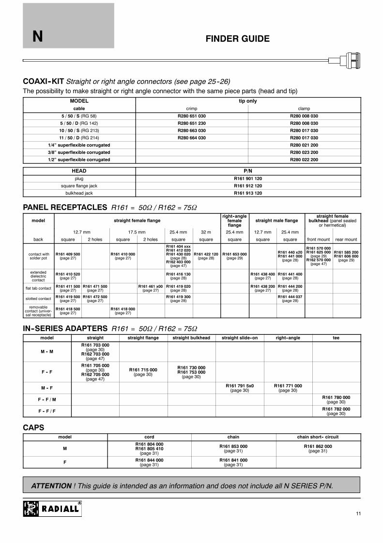
COAXI--KIT Straight or right angle connectors (see page 25--26)The possibility to make straight or right angle connector with the same piece parts (head and tip)
MODEL tip onlycable crimp clamp
5 / 50 / S (RG 58) R280 651 030 R280 008 030
5 / 50 / D (RG 142) R280 651 230 R280 008 030
10 / 50 / S (RG 213) R280 663 030 R280 017 030
11 / 50 / D (RG 214) R280 664 030 R280 017 030
1/4” superflexible corrugated R280 021 200
3/8” superflexible corrugated R280 023 200
1/2” superflexible corrugated R280 022 200
HEAD P/Nplug R161 901 120
square flange jack R161 912 120
bulkhead jack R161 913 120
PANEL RECEPTACLES R161 = 50 / R162 = 75
model straight female flangeright--anglefemaleflange
straight male flangestraight female
bulkhead (panel sealedor hermetical)
12.7 mm 17.5 mm 25.4 mm 32 m 25.4 mm 12.7 mm 25.4 mm
back square 2 holes square 2 holes square square square square square front mount rear mount
contact withsolder pot
R161 409 500(page 27)
R161 410 000(page 27)
R161 404 xxxR161 412 020R161 430 020(page 28)
R162 403 000(page 47)
R161 422 120(page 28)
R161 653 000(page 29)
R161 440 x20R161 441 000(page 28)
R161 570 000R161 625 000(page 29)
R162 570 000(page 47)
R161 585 200R161 606 000(page 29)
extendeddielectriccontact
R161 410 520(page 27)
R161 416 130(page 28)
R161 438 400(page 27)
R161 441 400(page 28)
flat tab contact R161 411 500(page 27)
R161 471 500(page 27)
R161 461 x00(page 27)
R161 419 020(page 28)
R161 438 200(page 27)
R161 444 200(page 28)
slotted contact R161 419 500(page 27)
R161 472 500(page 27)
R161 419 300(page 28)
R161 444 037(page 28)
removablecontact (univer-sal receptacle)
R161 418 500(page 27)
R161 418 000(page 27)
IN--SERIES ADAPTERS R161 = 50 / R162 = 75model straight straight flange straight bulkhead straight slide--on right--angle tee
M -- MR161 703 000(page 30)
R162 703 000(page 47)
F -- FR161 705 000(page 30)
R162 705 000(page 47)
R161 715 000(page 30)
R161 730 000R161 753 000(page 30)
M -- F R161 791 5x0(page 30)
R161 771 000(page 30)
F -- F / M R161 780 000(page 30)
F -- F / F R161 782 000(page 30)
CAPSmodel cord chain chain short-- circuit
MR161 804 000R161 805 410(page 31)
R161 853 000(page 31)
R161 862 000(page 31)
F R161 844 000(page 31)
R161 841 000(page 31)
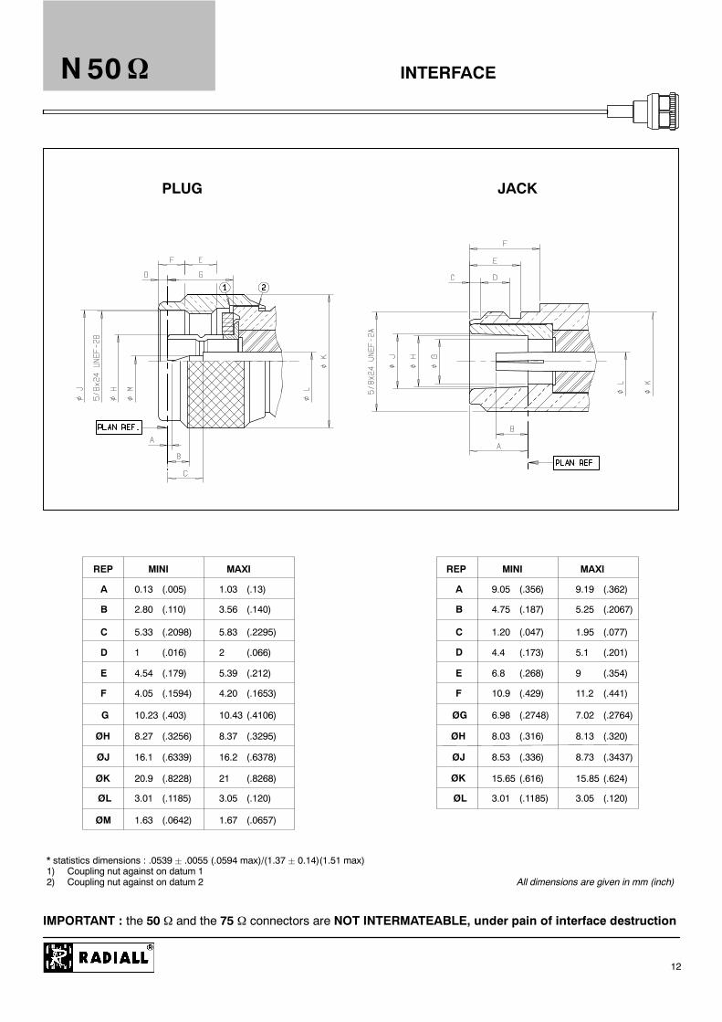
INTERFACE
REP MINI MAXI REP MINI MAXI
A
B
C
D
E
F
G
ØH
ØJ
ØK
ØL
ØM
A
B
C
D
E
F
ØG
ØH
ØJ
ØK
ØL
0.13 (.005) 1.03 (.13)
2.80 (.110) 3.56 (.140)
5.33 (.2098) 5.83 (.2295)
1 (.016) 2 (.066)
4.54 (.179) 5.39 (.212)
4.05 (.1594) 4.20 (.1653)
10.23 (.403) 10.43 (.4106)
8.27 (.3256) 8.37 (.3295)
16.1 (.6339) 16.2 (.6378)
20.9 (.8228) 21 (.8268)
3.01 (.1185) 3.05 (.120)
1.63 (.0642) 1.67 (.0657)
9.05 (.356) 9.19 (.362)
4.75 (.187) 5.25 (.2067)
1.20 (.047) 1.95 (.077)
4.4 (.173) 5.1 (.201)
6.8 (.268) 9 (.354)
10.9 (.429) 11.2 (.441)
6.98 (.2748) 7.02 (.2764)
8.03 (.316) 8.13 (.320)
8.53 (.336) 8.73 (.3437)
15.65 (.616) 15.85 (.624)
3.01 (.1185) 3.05 (.120)
PLUG JACK
* statistics dimensions : .0539 ¦ .0055 (.0594 max)/(1.37 ¦ 0.14)(1.51 max)1) Coupling nut against on datum 12) Coupling nut against on datum 2 All dimensions are given in mm (inch)
N 50
12
IMPORTANT : the 50 and the 75 connectors are NOT INTERMATEABLE, under pain of interface destruction

CHARACTERISTICSN 50
13
TEST/CHARACTERISTICS STANDARDREFERENCE VALUES/REMARKS
ELECTRICAL CHARACTERISTICS
Impedance 50
Frequency rangeDC--11 GHz
DC -- 2 GHz for COAXI-KITS
V.S.W.R. (typ.) FrequencyStraight models cable group : .085”
.141”
.250”5 S + 5 D10 S + 11 D
Right angle models 5 S + D10 S + 11 D
1 GHz1.031.031.031.051.041.041.04
2.5 GHz1.031.051.031.061.051.051.1
5 GHz1.051.051.051.11.091.181.20
11 GHz1.081.081.071.161.2
Intermodulation product (IMP 3)Standard connectorsIntermodulation connectorsHome made intermodulation cable assemblies
-- 90 dBm typ. (--133 dBc typ. / 20W)-- 110 dBm typ. (-- 153 dBc typ / 20 W)-- 125 dBm typ. (-- 165 dBc typ. / 20W)
Insertion loss straight connectorright--angle connector MIL
0.15 dB max at 10 GHz µ 0.05pF(GHz)0.15 dB max at 10 GHz µ 0.1 pF(GHz)
RF Leakage MIL -- 90 dB min from 2 to 3 GHz (interface)
Insulation resistance MIL 5000 M minContact resistance
center contactouter contact
MILInitial1 m0.2 m
After tests1.5 m
--
Working voltage in VRMSat sea level(at 70, 000 feet)
CECC
850 cable 5 / 50 1400 cable 10+11/50(250 cable 5 / 50) (400 cable 10+11/50)850 cable LMR200 1400 cable LMR 400/600(250 cable LMR200) (400 cable LMR 400/600)350 cable .085” / .141” 1400 cable .250(250 cable .085” / .141”) (400 cable .250)
Dielectric withstanding voltage in VRMSat sea level(at 70, 000 feet)
CECC
1500 cable 5 / 50 2500 cable 10/50(350 cable 5 / 50) (600 cable 10/50)1500 cable LMR200 2500 cable LMR400/600(350 cable LMR200) (600 cable LMR400/600)1000 cable .085” / .141” 2500 cable .250(350 cable .085 / .141”) (600 cable .250)
RF testing voltage sea level CECC 1500 VRMS (5 MHz sine wave)
MECHANICAL CHARACTERISTICS
Durability CECC 500 matings
Force to engage and disengage CECC 6.6 Ncm max (.58 Inch--pounds)
Recommended coupling nut torque40 to 60 Ncm (manual)130 Ncm (11.45 inch pounds) (with pliers R 282 202 000)170 Ncm (14.96 inch pounds) (with torque wrench R 282 303 020)
Proof torque CECC 170 Ncm (14.96 inch pounds)
Coupling nut retention force CECC 450 N (101.25 Lbs)
Cable retention force cable 5/50
cable 10/50cable 11/50cable .141”
CECC
150 N (33.75 Lbs) Single braid200 N (48 Lbs) Double braid300 N (67.5 Lbs)400 N (90 Lbs)270 N (60.75 Lbs)
Center contact retention force axial MIL27 N (6.08 Lbs) cables Ø 8 mm68 N (15.30 Lbs) cables Ø 8 mm
ENVIRONMENTAL CHARACTERISTICS
Temperature range standard modelssemi--rigid cables
CECC -- 55_C + 155_C-- 55_C + 105_C
Thermo cycling test CECC -- 55_C / + 155_C / 21 j.
Thermal shock CECC -- 40_C / + 155_C or -- 40_C / + 85 _C - 5 cycles
Hight temperature test CECC 125_C / 1000 H
Corrosion salt spray CECC 48 H

CHARACTERISTICSN 50
14
ENVIRONMENTAL CHARACTERISTICS
Vibration CECC Sinus 10 g / 10 - 500 Hz
Shock CECC 1/2 Sinus 50g / 11 ms
Moisture resistance clamp typecrimp type
IEC 529 IP 67IP 65 (with heatshrink sleeve)
Hermetic test CECC 10--5 bar. cm3/s
Leakage CECC Differential pressure 100 to 110 KPa : 1 bar cm3 / H
MATERIALS
Body / nut / center male contact / outer contact brass
Center female contact Treated beryllium copper
Ferrule Brass
Insulator PTFE
Gasket Silicon elastomer
PLATINGS
Standard Intermodulation models +COAXI--KIT
Body crimp + clamp typesolder type
BBRGold
Silver + BBRSilver
Coupling nut / Design BBR / cross knurled BBR / hex.
Center contacts Gold Silver
Outer contacts / Design BBR / slotted Silver + BBR / non slotted
POWER RANGE
Some connectors may feature different performance depending on the application they have been designed for, or according to the applicable cable.

Fig. 1 Fig. 2
Fig. 3
Fig. 1 Fig. 2
PLUGS
B
N 50
15
STRAIGHT PLUGS, FULL CRIMP TYPE, FOR FLEXIBLE CABLES (single piece body)
cable group part number figdimensions (mm) captured
center mounting notecable group part number fig.A B C D
pcentercontact
mounting note
2 / 50 / S + D R161 071 000 1 39.7 2.35 3.38 1 YES M09
2.6 / 50 / S+D R161 072 000 1 39.7 3.25 3.38 1.63 YES M09
5 / 50 / S R161 082 0002 38 5 5 41 3 11 YES M12
5 / 50 / S R161 082 2002 38.5 5.41 3.11 YES M12
LMR 200 cable
5 / 50 / D R161 083 000 2 38.5 5.8 3.11 YES M12
5 / 50 / D R161 083 137 3 38.5 5.8 3.11 YES M24 For intermodulation application / tool*
10 / 50 / S R161 075 000 2 40.2 11.05 7.46 YES M10
10.3 / 50 / S R161 075 060 2 40.2 11.05 7.46 YES M10 LMR 400 cable
10.3 / 50 / D R161 076 000 2 40.2 11.4 6.4 YES M10 ETHERNET cable
11 / 50 / D R161 088 000 240 2 11 4 7 46 YES
M10
11 / 50 / D R161 088 137 340.2 11.4 7.46 YES
M24 For intermodulation application / tool*
15.2 / 50 / S R161 079 220 2 49 15.87 11.96 YES M11 LMR 600 cable / solder type center contact
* Torque wrench : R282 303 020 (page 58)
STRAIGHT PLUGS, CLAMP TYPE, FOR FLEXIBLE CABLES
bl t b fidimensions (mm) captured
ticable group part number fig.A B C
capturedcenter contact mounting
2.6 / 50 / S + D R161 004 000 1 33.9 3.1 1.7 YES M01
5 / 50 / S + D R161 006 000 1 34.4 5.6 NO M02
5 / 50 / S + D R161 010 000 1 34.9 5.6 YES M03
10 + 11 / 50 / S + D R161 020 000 2 38.1 11.2 NO M04
10 + 11 / 50 / S + D R161 022 000 2 38.9 11.2 YES M05
Note : standard packaging = 50 pieces. For unit packaging, add ”W” after the P/N.
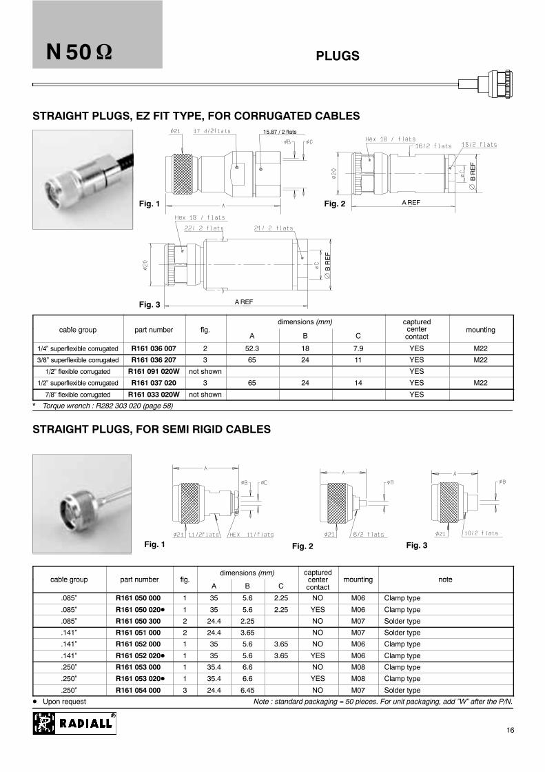
Fig. 1 Fig. 2
Fig. 3
15.87 / 2 flats
Fig. 1 Fig. 2 Fig. 3
PLUGS
AREF
BREF
A REF
BREF
N 50
16
STRAIGHT PLUGS, EZ FIT TYPE, FOR CORRUGATED CABLES
bl t b fidimensions (mm) captured
center ticable group part number fig.A B C
pcentercontact
mounting
1/4” superflexible corrugated R161 036 007 2 52.3 18 7.9 YES M22
3/8” superflexible corrugated R161 036 207 3 65 24 11 YES M22
1/2” flexible corrugated R161 091 020W not shown YES
1/2” superflexible corrugated R161 037 020 3 65 24 14 YES M22
7/8” flexible corrugated R161 033 020W not shown YES
* Torque wrench : R282 303 020 (page 58)
STRAIGHT PLUGS, FOR SEMI RIGID CABLES
cable group part number figdimensions (mm) captured
center mounting notecable group part number fig.A B C
pcentercontact
mounting note
.085” R161 050 000 1 35 5.6 2.25 NO M06 Clamp type
.085” R161 050 020D 1 35 5.6 2.25 YES M06 Clamp type
.085” R161 050 300 2 24.4 2.25 NO M07 Solder type
.141” R161 051 000 2 24.4 3.65 NO M07 Solder type
.141” R161 052 000 1 35 5.6 3.65 NO M06 Clamp type
.141” R161 052 020D 1 35 5.6 3.65 YES M06 Clamp type
.250” R161 053 000 1 35.4 6.6 NO M08 Clamp type
.250” R161 053 020D 1 35.4 6.6 YES M08 Clamp type
.250” R161 054 000 3 24.4 6.45 NO M07 Solder type
D Upon request Note : standard packaging = 50 pieces. For unit packaging, add ”W” after the P/N.

Fig. 2 Fig. 3
Fig. 4
Fig. 1
Fig. 5
Fig. 1 Fig. 2
PLUGS
Fig. 6
N 50
17
RIGHT ANGLE PLUGS, CRIMP TYPE, FOR FLEXIBLE CABLES
cable group part number figdimensions (mm) captured mounting notecable group part number fig.
A B C Dcaptured
center contact mounting note
2.6 / 50 / S R161 181 000 1 29.5 28 3.25 1.7 YES M18
2.6 / 50 / D R161 181 300 1 29.5 28 3.5 1.7 YES M18
5 / 50 / S R161 182 0001 34 5 28 5 41 3 1 YES M18
5 / 50 / S R161 182 2001 34.5 28 5.41 3.1 YES M18
LMR 200 cable
5 / 50 / D R161 183 000 1 34.5 28 5.8 3.1 YES M18
5 / 50 / D R161 183 137 5 35 28.3 5.8 3.1 YES M25 For intermodulation application / tool*
10 / 50 / S R161 184 000 2 37.5 11.05 YES M18
10 / 50 / S R161 185 000 3 42.4 33.2 11.05 7.46 YES M20 Full crimp
10.3 / 50 / S R161 184 036 2 46.25 11.05 YES M18 LMR 400 cable
11 / 50 / D R161 186 000 2 37.6 11.4 YES M18
11 / 50 / D R161 187 000 3 42.4 33.2 11.4 7.46 YES M20 Full crimp
11 / 50 / D R161 186 137 6 YES M18 For intermodulation application / tool*
15.2 / 50 / S R161 188 200 4 42.2 39.5 15.88 11.96 YES M19 LMR 600 cable
* Torque wrench : R282 303 020 (page 58)
RIGHT ANGLE PLUGS, CLAMP TYPE, FOR FLEXIBLE CABLES
bl t b fidimensions (mm) captured
ticable group part number fig.A B C
capturedcenter contact mounting
5 / 50 / S + D R161 157 000 1 32 32 5.6 YES M15
10 + 11 / 50 / S + D R161 168 000 2 34.85 49.4 11.2 YES M16
Note : standard packaging = 50 pieces. For unit packaging, add ”W” after the P/N.
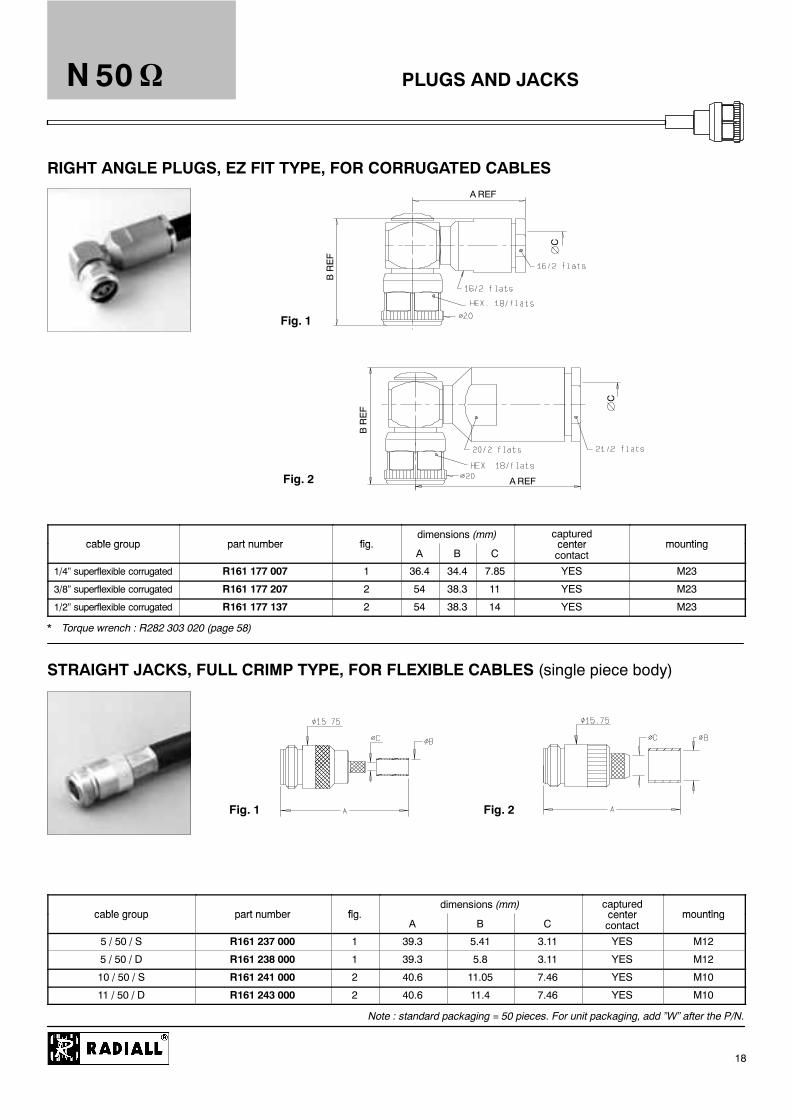
Fig. 1
Fig. 2
Fig. 1 Fig. 2
PLUGS AND JACKS
BREF
A REF
C
C
A REF
BREF
N 50
18
RIGHT ANGLE PLUGS, EZ FIT TYPE, FOR CORRUGATED CABLES
cable group part number figdimensions (mm) captured
center mountingcable group part number fig.A B C
pcentercontact
mounting
1/4” superflexible corrugated R161 177 007 1 36.4 34.4 7.85 YES M23
3/8” superflexible corrugated R161 177 207 2 54 38.3 11 YES M23
1/2” superflexible corrugated R161 177 137 2 54 38.3 14 YES M23
* Torque wrench : R282 303 020 (page 58)
STRAIGHT JACKS, FULL CRIMP TYPE, FOR FLEXIBLE CABLES (single piece body)
cable group part number figdimensions (mm) captured
center mountingcable group part number fig.A B C
pcentercontact
mounting
5 / 50 / S R161 237 000 1 39.3 5.41 3.11 YES M12
5 / 50 / D R161 238 000 1 39.3 5.8 3.11 YES M12
10 / 50 / S R161 241 000 2 40.6 11.05 7.46 YES M10
11 / 50 / D R161 243 000 2 40.6 11.4 7.46 YES M10
Note : standard packaging = 50 pieces. For unit packaging, add ”W” after the P/N.

Fig. 1 Fig. 2
Fig. 1 Fig. 2
JACKS
AREF
B B
A REF
N 50
19
STRAIGHT JACKS, CLAMP TYPE, FOR FLEXIBLE CABLES
bl t b fidimensions (mm) captured
ticable group part number fig.A B
capturedcenter contact mounting
5 / 50 / S + D R161 206 000 1 35.3 5.6 YES M03
10 + 11 / 50 / S + D R161 220 000 2 39.3 11.2 YES M05
STRAIGHT JACKS, EZ FIT TYPE, FOR CORRUGATED CABLES
cable group part number figdimensions (mm) captured
center mountingcable group part number fig.A B C
pcentercontact
mounting
1/4” superflexible corrugated R161 232 007 1 52.7 7.9 YES M22
3/8” superflexible corrugated R161 232 207 2 66 11 YES M22
1/2” superflexible corrugated R161 232 407 2 66 14 YES M22
1/2” flexible corrugated R161 230 020W not shown YES
7/8” flexible corrugated R161 231 020W not shown YES
Note : standard packaging = 50 pieces. For unit packaging, add ”W” after the P/N.

Fig. 1 Fig. 2
Fig. 1
Fig. 2
JACKSN 50
20
STRAIGHT JACKS, FOR SEMI RIGID CABLES
bl t b fidimensions (mm) captured
center ti tcable group part number fig.A B C
pcentercontact
mounting note
.141” R161 227 000 1 35.5 5.6 3.65 NO M06 Clamp type
.141” R161 227 020D 1 35.5 5.6 3.65 YES M06 Clamp type
.141” R161 226 020 2 32 3.65 NO M21 Solder type
D Upon request
25.4 mm SQUARE FLANGE, STRAIGHT JACKS, FULL CRIMP TYPE, FOR FLEXIBLE CABLES(single piece body) (25.4 mm = 1 inch)
bl t b fidimensions (mm) captured
center ti lcable group part number fig.A B C D
pcentercontact
mounting panel
2 / 50 / S + D R161 281 000 1 40.3 3.38 2.55 1 YES M09 P01
2.6 / 50 / S+D R161 281 300 1 40.3 3.38 3.25 1.63 YES M09 P01
5 / 50 / S R161 282 000 2 39.3 5.41 3.11 YES M12 P01
5 / 50 / D R161 283 000 2 39.3 5.8 3.11 YES M12 P01
10 / 50 / S R161 286 000 2 40.6 11.05 7.46 YES M10 P01
11 / 50 / D R161 286 200 2 40.6 11.4 7.46 YES M10 P01
Note : standard packaging = 50 pieces. For unit packaging, add ”W” after the P/N.

Fig. 1
Fig. 2
Fig. 1
Fig. 2
JACKS
B
A REF
AREF
B
N 50
21
25.4 mm SQUARE FLANGE, STRAIGHT JACKS, CLAMP TYPE FOR FLEXIBLE CABLES(25.4 mm = 1 inch)
bl t b fidimensions (mm) captured
ti lcable group part number fig.A B C
capturedcenter contact
mounting panel
2.6 / 50 / S + D R161 252 000 1 34.3 3.1 1.7 YES M01 P01
5 / 50 / S + D R161 256 000 1 35.4 5.6 YES M03 P01
10 + 11 / 50 / S + D R161 270 000 2 39.3 11.2 YES M05 P01
25.4 mm SQUARE FLANGE, STRAIGHT JACKS, EZ FIT TYPE, FOR CORRUGATED CABLES(25.4 mm = 1 inch)
bl t b fidimensions (mm) captured
center ti lcable group part number fig.A B
pcentercontact
mounting panel
1/4” superflexible corrugated R161 279 007 1 52.7 7.9 YES M22 P01
3/8” superflexible corrugated R161 279 207 2 66 11 YES M22 P01
1/2” superflexible corrugated R161 279 407 2 66 14 YES M22 P01
Note : standard packaging = 50 pieces. For unit packaging, add ”W” after the P/N.
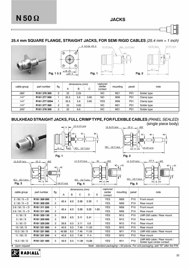
Fig. 1 Fig. 2Fig. 1 & 2
Fig. 1
Fig. 3
Fig. 2
Fig. 4 Fig. 5
JACKSN 50
22
25.4 mm SQUARE FLANGE, STRAIGHT JACKS, FOR SEMI RIGID CABLES (25.4 mm = 1 inch)
cable group part number figdimensions (mm) captured
center mounting panel notecable group part number fig.A B C
centercontact
mounting panel note
.085” R161 276 300 2 32 2.25 NO M21 P01 Solder type
.141” R161 277 000 1 35.5 5.6 3.65 NO M06 P01 Clamp type
.141” R161 277 020D 1 35.5 5.6 3.65 YES M06 P01 Clamp type
.141” R161 277 300 2 32 3.65 NO M21 P01 Solder type
.250” R161 278 300 2 32 6.6 NO M21 P01 Solder type
BULKHEADSTRAIGHT JACKS,FULLCRIMPTYPE, FORFLEXIBLECABLES (PANEL SEALED)(single piece body)
cable group part number figdimensions (mm) captured
center mounting panel notecable group part number fig.A B C D E
centercontact
mounting panel note
2 / 50 / S + D R161 309 000 140 4 6 5 3 38 2 35 1
YES M09 P10 Front mount
2 / 50 / S + D R161 309 200 240.4 6.5 3.38 2.35 1
YES M09 P10 Rear mount
2.6 / 50 / S + D R161 311 200 140 4 6 5 3 38 3 25 1 63
YES M09 P10 Front mount
2.6 / 50 / S + D R161 311 300 240.4 6.5 3.38 3.25 1.63
YES M09 P10 Rear mount
5 / 50 / S R161 329 130 339 8 6 5 3 11 5 41
YES M12 P10 LMR 200 cable / Rear mount
5 / 50 / S R161 329 000 339.8 6.5 3.11 5.41
YES M12 P10 Rear mount
5 / 50 / D R161 329 200 3 39.8 6.5 3.11 5.8 YES M12 P10 Rear mount
10 / 50 / S R161 331 000 4 40.6 6.5 7.46 11.05 YES M10 P10 Rear mount
10.3 / 50 / S R161 331 060 5 46.88 6.5 7.46 11.05 YES M11 P10 LMR 400 cable / Rear mount
11 / 50 / D R161 331 200 4 40.6 6.5 7.46 11.4 YES M10 P10 Rear mount
15.2 / 50 / S R161 331 400 5 49.9 6.5 11.96 15.88 YES M11 P10 LMR 600 cable / Rear mount /Solder type center contact
D Upon request Note : standard packaging = 50 pieces. For unit packaging, add ”W” after the P/N.

JACKS
Fig. 1
Fig. 3
Fig. 2
Fig. 1 Fig. 2AREF
B B
AREF
N 50
23
BULKHEAD STRAIGHT JACKS, CLAMP TYPE, FOR FLEXIBLE CABLES (PANEL SEALED)
cable group part number figdimensions (mm) captured
center mounting panel notecable group part number fig.A B C D
centercontact
mounting panel note
2.6 / 50 / S + D R161 321 000 1 34.3 8 3.1 1.7 YES M01 P10 Front mount
2.6 / 50 / S + D R161 322 000 2 34.3 6.5 3.1 1.7 YES M01 P10 Rear mount
5 / 50 / S + D R161 325 000 2 35.4 6.5 5.6 YES M01 P10 Rear mount
10 + 11 / 50 / S + D R161 332 000 3 43 6.5 11.2 NO M04 P10 Rear mount
BULKHEAD STRAIGHT JACKS, EZ FIT TYPE, FOR CORRUGATED CABLES
bl t b fidimensions (mm) captured
ti lcable group part number fig.A B C
capturedcenter contact
mounting panel
1/4” superflexible corrugated R161 341 007 1 52.7 6.5 7.9 YES M22 P10
3/8” superflexible corrugated R161 341 207 2 66 6.5 11 YES M22 P10
1/2” superflexible corrugated R161 341 407 2 66 6.5 14 YES M22 P10
Note : standard packaging = 50 pieces. For unit packaging, add ”W” after the P/N.

Fig. 1
Fig. 3
Fig. 2
Fig. 4
JACKSN 50
24
BULKHEAD STRAIGHT JACKS, FOR SEMI RIGID CABLES (PANEL SEALED)
cable group part number figdimensions (mm) captured
center mounting panel notecable group part number fig.A B C D
pcentercontact
mounting panel note
.085” R161 335 200 1 32 6.5 2.25 NO M21 P10 Solder type / Rear mount
.141” R161 323 000 2 35.5 8 5.6 3.65 NO M06 P10 Clamp type / Front mount
.141” R161 323 020D 2 35.5 8 5.6 3.65 YES M06 P10 Clamp type / Front mount
.141” R161 323 200 4 35.5 6.5 5.6 3.65 YES M06 P10 Clamp type / Rear mount
.141” R161 336 000 1 32 6.5 3.65 NO M21 P10 Solder type / Rear mount
.141” R161 336 200 3 32 6.5 3.65 NO M21 P10 Solder type / Front mount
.250” R161 337 200 1 32 6.5 6.6 NO M21 P10 Solder type / Rear mount
D Upon request Note : standard packaging = 50 pieces. For unit packaging, add ”W” after the P/N.

COAXI--KIT
"""" ConceptYou can mount any tip ( cable attachment ) with any head ( interface ) either in a straight or right angle configuration.
Head + tip = Straight or R/A
"""" Advantages of flexibilityA lot of combinations are possible by screwing the chosen tips and heads together since any tip is intermateable with anyhead.During base station installation, you may need, in a field situation, to change the configuration at the last minute:D With the same head interface, the Coaxi--kit connector can be mounted either in a straight or a right angle position.
It can be useful when the cable assembly is too short to be connected in a straight position. Using a Coaxi--kit, theexisting cable assembly can be utilized by orienting the head to a right angle position, eliminating the need for a newcable assembly with a right angle connector.
D One head can be used for all the different cables from a 5 mm flexible cable size to a 1/2 inch corrugated cable!D Thesame tip canbeused for all the different interfaces of theBTSequipment whichare suppliedwith 7/16or Ndepend-
ing on the power transmitted, or manufacturer options.
"""" Advantages of cost savingD Bymanaginga lower number of P/N’s you’remaking cost savings in qualification, purchasing, and inventory. For exam-
ple, Radiall’s full range represents 14 P/N ( 5 heads & 9 tips ) which are equivalent to 90 connector combinations (near7 times more ! ). The other advantage is the increase of volume by P/N which gives lower cost.
D Compared to a standard right angle connector, Coaxi--kit connectors use a simpler design. Including the price of thehead & the tip, Coaxi--kit is a low cost right angle connector.
"""" Less stockD By purchasing a Coaxi--kit, you eliminate separate stocks of complete connectors with different body styles and cable
attachments, limiting the risk to run out of stock.
"""" Main performance characteristicsThese connectors have the same performances as standard ones, except that the frequency ranges are:
-- for flexible cables, from DC to 2.5 GHz,-- for corrugated cables, DC--11 GHz: N series and DC--7.5 GHz: 7/16 series.Coaxi--kit with EZ fit cable attachment features a typical intermodulation value of --110 dBm.
"""" The product rangeD Heads:
-- 7/16 series: plug and flange jack-- N series: plug, flange jack and bulkhead jack
D Tips (cable attachment):-- Crimp or clamp type on flexible cables (RG 58, RG 142, RG 213 or RG 214)-- EZ fit type on super flexible corrugated cables (1/4”, 3/8” or 1/2”)
D All tips and heads are packaged by 20 pieces.
N 50
25

Fig. 1 Fig. 3Fig. 2
Fig. 1 Fig. 2
Fig. 3 Fig. 4
COAXI--KITN 50
26
Heads for COAXI-KIT
part number fig.captured
center contact panel note
R161 901 120 1 YES Plug / tool R282 303 020 page 58
R161 912 120 2 YES P01 Panel flange jack
R161 913 120 3 YES P10 Panel bulkhead jack
Tips for COAXI-KIT
bl t b Figdimensions (mm)
ti fi i h tcable group part number Fig.A B C
mounting finish note
5 / 50 / S + D R280 008 030 1 M28 Clamp type
5 / 50 / S R280 651 030 4 24 3.1 5.41 M27 Crimp type
5 / 50 / D R280 651 230 4 24 3.1 5.8 M27 Crimp type
10 / 50 / S R280 663 030 4 21.5 7.46 11.05 M27 Crimp type
10 + 11 / 50 / S + D R280 017 030 2 M29 Silver + BBR Clamp type
10 + 11 / 50 / D R280 664 030 4 21.5 7.46 11.4 M27 Crimp type, RG393
1/4” superflexible corrugated R280 021 200 3 41.7 4.7 7.95 M30 EZ fit type
1/2” superflexible corrugated R280 022 200 3 41.7 8.8 14 M30 EZ fit type
3/8” superflexible corrugated R280 023 200 3 42.2 7.1 11 M30 EZ fit type
Note : standard packaging = 20 pieces. For unit packaging, add ”W” after the P/N.
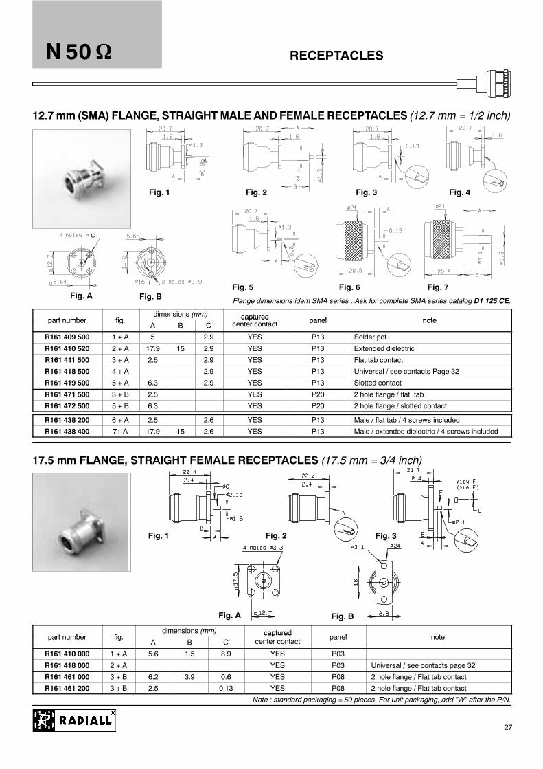
Fig. 1 Fig. 2 Fig. 3 Fig. 4
Fig. 5 Fig. 6 Fig. 7Fig. A Fig. B
Fig. 1 Fig. 2
Fig. A Fig. B
Fig. 3
RECEPTACLES
C
N 50
27
12.7mm (SMA) FLANGE, STRAIGHTMALE ANDFEMALE RECEPTACLES (12.7 mm = 1/2 inch)
Flange dimensions idem SMA series . Ask for complete SMA series catalog D1 125 CE.
part number figdimensions (mm) captured panel notepart number fig.A B C
capturedcenter contact panel note
R161 409 500 1 + A 5 2.9 YES P13 Solder pot
R161 410 520 2 + A 17.9 15 2.9 YES P13 Extended dielectric
R161 411 500 3 + A 2.5 2.9 YES P13 Flat tab contact
R161 418 500 4 + A 2.9 YES P13 Universal / see contacts Page 32
R161 419 500 5 + A 6.3 2.9 YES P13 Slotted contact
R161 471 500 3 + B 2.5 YES P20 2 hole flange / flat tab
R161 472 500 5 + B 6.3 YES P20 2 hole flange / slotted contact
R161 438 200 6 + A 2.5 2.6 YES P13 Male / flat tab / 4 screws included
R161 438 400 7+ A 17.9 15 2.6 YES P13 Male / extended dielectric / 4 screws included
17.5 mm FLANGE, STRAIGHT FEMALE RECEPTACLES (17.5 mm = 3/4 inch)
part number figdimensions (mm) captured
panel notepart number fig.A B C
capturedcenter contact
panel note
R161 410 000 1 + A 5.6 1.5 8.9 YES P03
R161 418 000 2 + A YES P03 Universal / see contacts page 32
R161 461 000 3 + B 6.2 3.9 0.6 YES P08 2 hole flange / Flat tab contact
R161 461 200 3 + B 2.5 0.13 YES P08 2 hole flange / Flat tab contact
Note : standard packaging = 50 pieces. For unit packaging, add ”W” after the P/N.
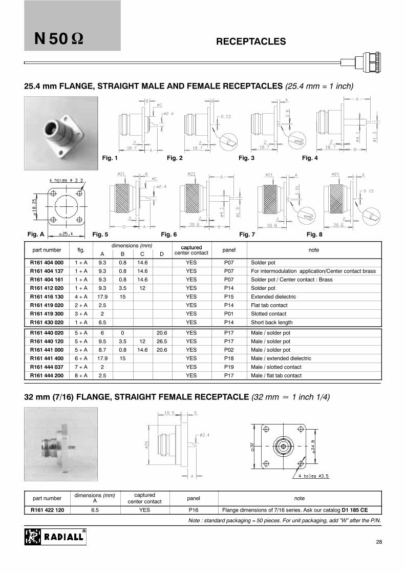
Fig. 1 Fig. 2 Fig. 3 Fig. 4
Fig. 5 Fig. 6 Fig. 8Fig. A Fig. 7
RECEPTACLESN 50
28
25.4 mm FLANGE, STRAIGHT MALE AND FEMALE RECEPTACLES (25.4 mm = 1 inch)
part number figdimensions (mm) captured panel notepart number fig.
A B C Dcaptured
center contact panel note
R161 404 000 1 + A 9.3 0.8 14.6 YES P07 Solder pot
R161 404 137 1 + A 9.3 0.8 14.6 YES P07 For intermodulation application/Center contact brass
R161 404 161 1 + A 9.3 0.8 14.6 YES P07 Solder pot / Center contact : Brass
R161 412 020 1 + A 9.3 3.5 12 YES P14 Solder pot
R161 416 130 4 + A 17.9 15 YES P15 Extended dielectric
R161 419 020 2 + A 2.5 YES P14 Flat tab contact
R161 419 300 3 + A 2 YES P01 Slotted contact
R161 430 020 1 + A 6.5 YES P14 Short back length
R161 440 020 5 + A 6 0 20.6 YES P17 Male / solder pot
R161 440 120 5 + A 9.5 3.5 12 26.5 YES P17 Male / solder pot
R161 441 000 5 + A 8.7 0.8 14.6 20.6 YES P02 Male / solder pot
R161 441 400 6 + A 17.9 15 YES P18 Male / extended dielectric
R161 444 037 7 + A 2 YES P19 Male / slotted contact
R161 444 200 8 + A 2.5 YES P17 Male / flat tab contact
32 mm (7/16) FLANGE, STRAIGHT FEMALE RECEPTACLE (32 mm 1 inch 1/4)
part number dimensions (mm)A
capturedcenter contact
panel note
R161 422 120 6.5 YES P16 Flange dimensions of 7/16 series. Ask our catalog D1 185 CE
Note : standard packaging = 50 pieces. For unit packaging, add ”W” after the P/N.

Fig. 1
Fig. 3
Fig. 2
Fig. 4
RECEPTACLESN 50
29
25.4 mm FLANGE, RIGHT-ANGLE FEMALE RECEPTACLE (25.4 mm = 1 inch)
t bdimensions (mm) captured
l tpart numberA B C
capturedcenter contact
panel note
R161 653 000 36.9 34.4 2.5 YES P02 Solder pot
BULKHEAD STRAIGHT RECEPTACLES (Panel sealed or HERMETIC)
t b fidimensions (mm) captured
l tpart number fig.A B C
capturedcenter contact
panel note
R161 570 000 1 28 4.5 2.4 YES P09 Front mount
R161 585 200 2 34.6 6.5 2.4 YES P10 Rear mount / Panel Sealed
R161 586 137 4 30.5 6.5 2.4 YES P10For intermodulation application / Rear mount/ Panel Sealed
R161 606 000 2 34.6 6.5 2.4 YES P10 Rear mount / Panel Hermetic
R161 625 000 3 34 6.5 2.5 YES P10 Front mount / Panel Hermetic
Note : standard packaging = 50 pieces. For unit packaging, add ”W” after the P/N.

Fig. 1 Fig. 2
Fig. 3
Fig. 4
Fig. 5
Fig. 8Fig. 7Fig. 6
Fig. 10Fig. 9
IN SERIES ADAPTERS
Fig. 11
N 50
30
IN SERIES ADAPTERS
t b fidimensions (mm)
l tpart number fig.A B
panel note
R161 703 000 1 36.7 M -- M
R161 705 000 2 37.5 F -- F
R161 715 000 3 37.5 P01 F -- F / Flange
R161 730 000 4 37.5 6.5 P10 F -- F / Bulkhead panel sealed
R161 753 000 5 38 6.5 P10 F -- F / Hermetic / bulkhead
R161 771 000 6 34.4 34 M -- F / Right-angle
R161 780 000 7 42 36.9 TEE F -- F/M
R161 782 000 8 42 29.1 TEE F -- F/F
R161 791 500 9 37.37 Push -- on male / female screwing*
R161 791 530D 10 37.12 screwing male / Push -- on female*
R161 792 500D 11 37.12 Push -- on male / male screwing*
* Push--on adapter, see our catalog D1 036 DE Note : standard packaging = 50 pieces. For unit packaging, add ”W” after the P/N.

Fig. 5
Fig. 1 Fig. 3Fig. 2
Fig. 4 Fig. 6
CAPSN 50
31
PROTECTIVE CAPS
part number figdimensions (mm)
notepart number fig.A B
note
R161 804 000 1 13.9 3.8 Male with cord
R161 805 410 2 13.9 2 Male with cord
R161 841 000 3 20.4 3.9 Female with chain
R161 844 000 4 20.4 3.8 Female with cord
R161 853 000 5 13.9 3.9 Male with chain
R161 862 000 6 20.1 3.9 Male short circuit with chain
Note : standard packaging = 50 pieces. For unit packaging, add ”W” after the P/N.
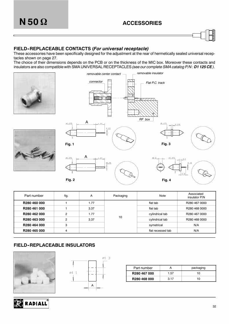
removable center contact removable insulator
connector Flat P.C. track
RF box
These accessories have been specifically designed for the adjustment at the rear of hermetically sealed universal recep-tacles shown on page 27.The choice of their dimensions depends on the PCB or on the thickness of the MIC box. Moreover these contacts andinsulators are also compatiblewith SMAUNIVERSALRECEPTACLES (see our complete SMAcatalog P/N :D1125CE ).
A
A
Fig. 1
Fig. 2
Fig. 3
Fig. 4
A
ACCESSORIESN 50
32
FIELD--REPLACEABLE CONTACTS (For universal receptacle)
Part number fig. A Packaging NoteAssociatedinsulator P/N
R280 460 000 1 1.77 flat tab R280 467 0000
R280 461 000 1 3.37 flat tab R280 468 0000
R280 462 000 2 1.7710
cylindrical tab R280 467 0000
R280 463 000 2 3.3710
cylindrical tab R280 468 0000
R280 464 000 3 symetrical N/A
R280 465 000 4 flat recessed tab N/A
FIELD--REPLACEABLE INSULATORS
Part number A packaging
R280 467 000 1.57 10
R280 468 000 3.17 10

ACCESSORIES
B
N 50
33
HEATSHRINK SLEEVES
These heatshrink sleeves guarantee an IP 65 moisture resistance on crimp type models and an IP 67 moisture resistance on clamp type models.
Cable group part number A B Packaging
2 / 50 R280 637 010 3.2 22
2.6 / 50 R280 637 020 4.8 22
5 / 50--LMR200 R280 637 030 6.4 25.4
10 / 50--11 / 50--LMR400--1/4“spiraled R280 637 040 12 45
100
3/8“ superflexible corrugated--1/2“ superflexible corrugated
--LMR600R280 637 050 24 50

D1 030 DE
D1 032 DE
What is INTERMODULATION ?
IM (abbreviation for InterModulation) is anundesiredmodulation which leads to a distortion ofthe output High Frequency carrier.It is defined as the ratio of the 3rd orderintermodulation products against the incidentsignal power because, the most troublesome IMproducts are those of 3rd order.For more detailed information, please ask for ourapplication guide where we present :
-- our intermodulation measurement system-- our product range
BBR (Bright Bronze RADIALL) plating has beenspecifically developed and employed by RADIALLfor its excellence in Intermodulation sensitiveapplications.
For more detailed information, an applicationguide about the BBR high quality plating isavailable upon request.
N 50
34

Radiall proposes you 3 types of cable assemblies with N type connectors.
This range includes standard and custom cable assemblies, offering you standard, main and high level of intermodulationperformance.(See our intermodulation application guide : D1 032 DE).
z Standard level : IMP3 = --90 dBm typical (see page 36--37)The main characteristics of this range are :
D cross-knurled coupling nutD coupling torque 130 N cm (with pliers R282 202 000)D slotted outer contactD plating : BBR (Bright Bronze Radiall)D connectors also available uncabledD 3 types of cable mounting : full crimp, clamp or solder.
z Main level : IMP3 = --110 dBm typical(see page 38--39)The main characteristics of this range are :
D hexagonal coupling nut (170 Ncm)D non-slotted outer contactD plating : silver (finish : strike of BBR)D connectors also available uncabled (exceptfor SHF cable)
D 3 types of cable mounting : full crimp, clampor solder.
z High level : IMP3 = --125 dBm typical (see page 40--41)The main characteristics of this range are :
D hexagonal coupling nut (170 Ncm)D non-slotted outer contactD plating : silver (finish : strike of BBR)D connectors only available for cable assembliesmade by Radiall
D only solder type models :the most rigid cable attachment
D Intermodulation curves available upon request.
D Moisture resistance : IP 68 overmolding.
CABLE ASSEMBLIESN 50
35
--90 dBm CUSTOM CABLE ASSEMBLIES
L : Overall length ¦¦¦¦ 2%
N 50
36
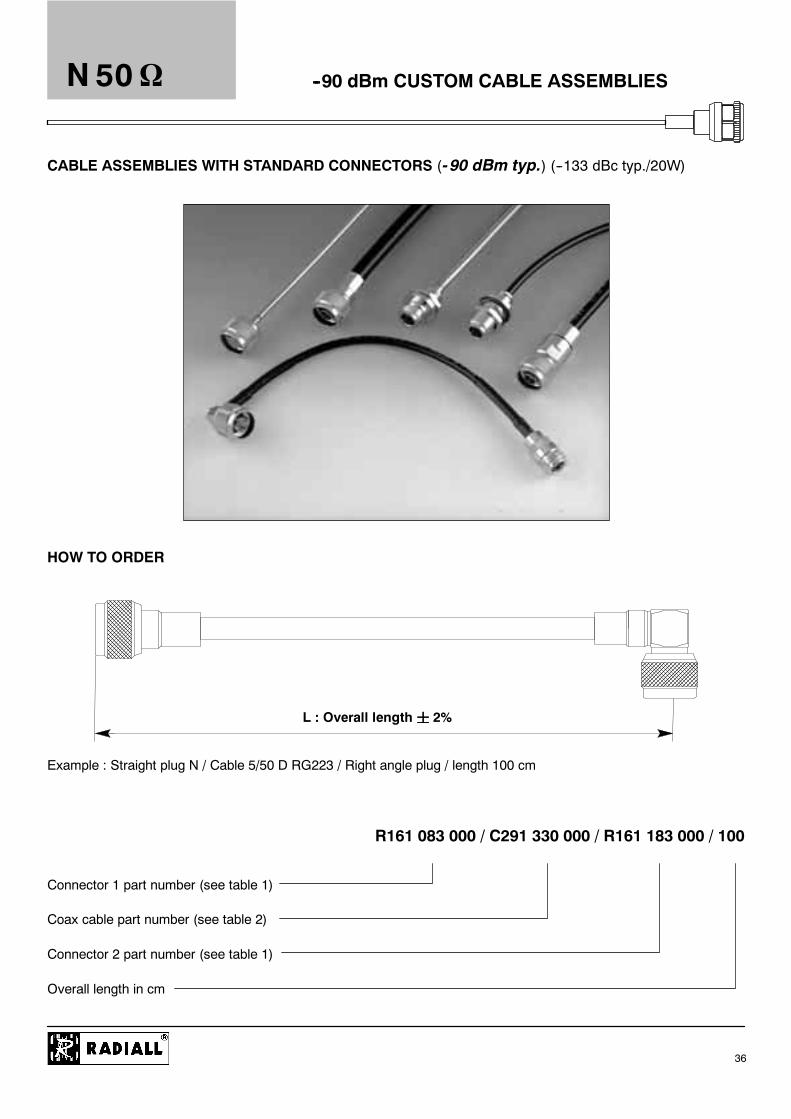
CABLE ASSEMBLIES WITH STANDARD CONNECTORS (- 90 dBm typ.) (--133 dBc typ./20W)
HOW TO ORDER
Example : Straight plug N / Cable 5/50 D RG223 / Right angle plug / length 100 cm
R161 083 000 / C291 330 000 / R161 183 000 / 100
Connector 1 part number (see table 1)
Coax cable part number (see table 2)
Connector 2 part number (see table 1)
Overall length in cm
--90 dBm CUSTOM CABLE ASSEMBLIESN 50
37
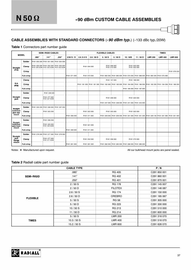
CABLE ASSEMBLIES WITH STANDARD CONNECTORS (- 90 dBm typ.) (--133 dBc typ./20W)
Table 1 Connectors part number guide
MODELSEMI--RIGID CABLES FLEXIBLE CABLES TIMES
MODEL.085” .141” .250” 2/50 S / D 2.6 /5 0 S 2.6 / 50 D 5 / 50 S 5 / 50 D 10 / 50S 11 / 50 D LMR 200 LMR 400 LMR 600
Solder R161 050 300 R161 051 000 R161 054 000
StraightClamp R161 050 000
R161 050 020DR161 052 000R161 052 020D
R161 053 000R161 053 020D R161 004 000 R161 006 000
R161 010 000R161 020 000R161 022 000Straight
plugCrimp R161 079 220
Full crimp R161 071 000 R161 072 000 R161 082 000 R161 083 000 R161 075 000 R161 088 000 R161 082 200 R161 075 060
Clamp R161 157 000 R161 168 000
R/Aplug Crimp R161 181 000 R161 181 300 R161 182 000 R161 183 000 R161 184 000 R161 186 000 R161 182 200 R161 184 036 R161 188 200plug
Full crimp R161 185 000 R161 187 000
Solder R161 226 020
Straightjack Clamp R161 277 000
R161 227 020D R161 206 000 R161 220 000jack
Full crimp R161 237 000 R161 238 000 R161 241 000 R161 243 000
StraightSolder R161 335 200 R161 336 000 R161 337 200
Straightbulkheadjack rear
Clamp R161 323 200 R161 322 000 R161 325 000 R161 332 000jack rearmount
Full crimp R161 309 200 R161 311 300 R161 329 000 R161 329 200 R161 331 000 R161 331 200 R161 329 130 R161 331 060 R161 331 400
St i htSolder R161 336 200
Straightbulkheadjack frontmount
Clamp R161 323 000R161 323 020D R161 321 000
jack frontmount
Full crimp R161 309 000 R161 311 200
StraightSolder R161 276 300 R161 277 300 R161 278 300
Straightjackflange
t
Clamp R161 277 000R161 277 020D R161 252 000 R161 256 000 R161 270 000
flangemount
Full crimp R161 281 000 R161 281 300 R161 282 000 R161 283 000 R161 286 000 R161 286 200
Notes : D Manufactured upon request. All our bulkhead mount jacks are panel sealed.
Table 2 Radiall cable part number guide
CABLE TYPE P / N
.085” RG 405 C291 850 001
SEMI--RIGID .141” RG 402 C291 860 001SEMI RIGID.250” RG 401 C291 870 001
2 / 50 S RG 178 C291 145 007
2 / 50 D FILOTEX C291 146 087
2.6 / 50 S RG 174 C291 150 000
FLEXIBLE2.6 / 50 D OREBRO C291 185 067
FLEXIBLE5 / 50 S RG 58 C291 305 000
5 / 50 D RG 223 C291 330 000
10 / 50 S RG 213 C291 510 000
11 / 50 D RG 214 C291 600 000
5 / 50 S LMR 200 C291 316 070
TIMES 10.3 / 50 S LMR 400 C291 516 070TIMES15.2 / 50 S LMR 600 C291 626 070

--110 dBm CABLE ASSEMBLIES
L : Overall length ¦¦¦¦ 2%
N 50
38
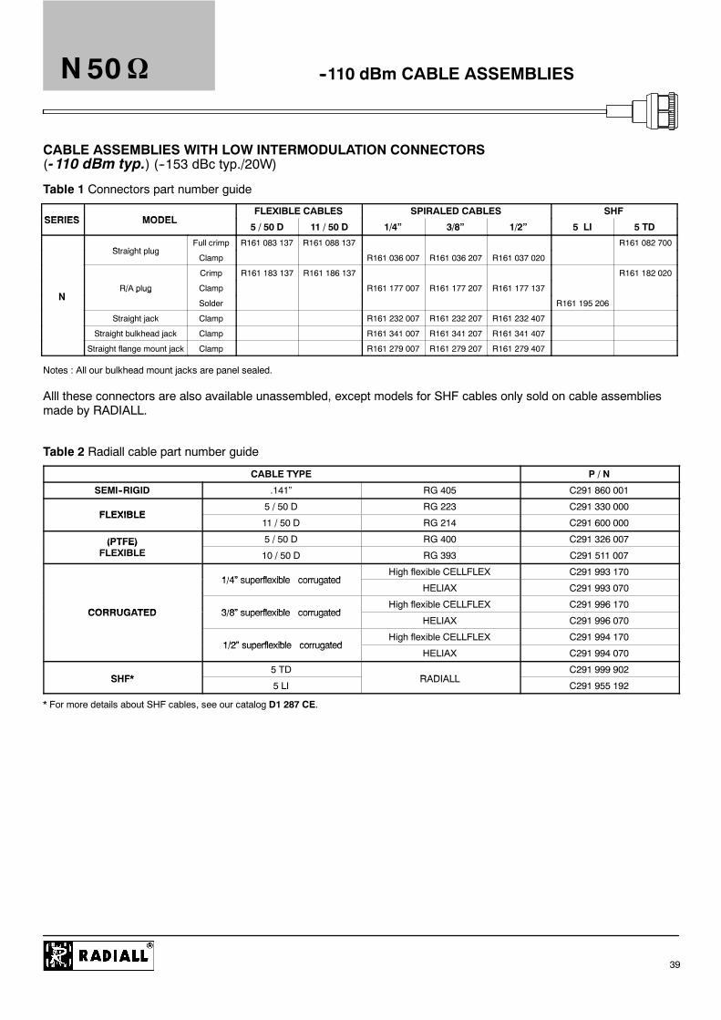
CABLE ASSEMBLIES WITH LOW INTERMODULATION CONNECTORS(- 110 dBm typ.) (--153 dBc typ./20W)
HOW TO ORDER
Example : Straight plug N / Cable 11 / 50 D RG 214 / Right angle plug N / length 100 cm
R161 088 137 / C291 600 000 / R161 186 137 / 100
Connector 1 part number (see table 1)
Coax cable part number (see table 2)
Connector 2 part number (see table 1)
Overall length in cm
--110 dBm CABLE ASSEMBLIESN 50
39
CABLE ASSEMBLIES WITH LOW INTERMODULATION CONNECTORS(- 110 dBm typ.) (--153 dBc typ./20W)
Table 1 Connectors part number guide
SERIES MODELFLEXIBLE CABLES SPIRALED CABLES SHF
SERIES MODEL5 / 50 D 11 / 50 D 1/4” 3/8” 1/2” 5 LI 5 TD
Straight plugFull crimp R161 083 137 R161 088 137 R161 082 700
Straight plugClamp R161 036 007 R161 036 207 R161 037 020
Crimp R161 183 137 R161 186 137 R161 182 020
NR/A plug Clamp R161 177 007 R161 177 207 R161 177 137
N/ p ug
Solder R161 195 206
Straight jack Clamp R161 232 007 R161 232 207 R161 232 407
Straight bulkhead jack Clamp R161 341 007 R161 341 207 R161 341 407
Straight flange mount jack Clamp R161 279 007 R161 279 207 R161 279 407
Notes : All our bulkhead mount jacks are panel sealed.
Alll these connectors are also available unassembled, except models for SHF cables only sold on cable assembliesmade by RADIALL.
Table 2 Radiall cable part number guide
CABLE TYPE P / N
SEMI--RIGID .141” RG 405 C291 860 001
FLEXIBLE5 / 50 D RG 223 C291 330 000
FLEXIBLE11 / 50 D RG 214 C291 600 000
(PTFE) 5 / 50 D RG 400 C291 326 007(PTFE)FLEXIBLE 10 / 50 D RG 393 C291 511 007
1/4” superflexible corrugatedHigh flexible CELLFLEX C291 993 170
1/4” superflexible corrugatedHELIAX C291 993 070
CORRUGATED 3/8” superflexible corrugatedHigh flexible CELLFLEX C291 996 170
CORRUGATED 3/8” superflexible corrugatedHELIAX C291 996 070
1/2” superflexible corrugatedHigh flexible CELLFLEX C291 994 170
1/2” superflexible corrugatedHELIAX C291 994 070
SHF*5 TD
RADIALLC291 999 902
SHF*5 LI
RADIALLC291 955 192
* For more details about SHF cables, see our catalog D1 287 CE.

--125 dBm CABLE ASSEMBLIES
L : Overall length ¦¦¦¦ 2%
N 50
40
VERY LOW INTERMODULATION CABLE ASSEMBLIES (- 125 dBm typ.) (--165 dBc typ./20W)
HOW TO ORDER
Example : Straight plug N / Cable 1/4” high flexible Cellflex / right angle plug N / length 50 cm
865 48 030 / C291 993 170 / 865 48 040 / 50
Connector 1 part number (see table 1)
Coax cable part number (see table 2 page 39)
Connector 2 part number (see table 1)
Overall length in cm

--125 dBm CABLE ASSEMBLIES
Fig 6
Fig 5
Fig 4
L
Fig 1
Fig 2
Fig 3
L
N 50
41
VERY LOW INTERMODULATION CABLE ASSEMBLIES (- 125 dBm typ.) (--165 dBc typ./20W)
Connectors part number guide
SERIESMODEL SUPERFLEXIBLE CORRUGATED SEMI RIGID (PTFE) FLEXIBLE
SERIESMODEL
Solder Type 1/4” 3/8” 1/2” .141” RG 400 RG 393
Straight plug 865 48 030 865 48 080 865 48 120 865 48 000
R/A plug 865 48 040 865 48 090 865 48 130 865 48 010
N Straight jack 865 48 050 865 48 100 865 48 140 Please consult usN
Straight panel sealed bulkhead jack 865 48 060 865 48 110 865 48 150 865 48 020
Please consult us
Straight flange mount jack 865 48 070 865 48 170 865 48 160
These connectors are only available for cable assemblies made by Radiall.
Cable assemblies with standard lengths
CONNECTOR 1 CABLE CONNECTOR 2 Cable assemblyFig
SERIES Model Type Length (m) Series Model P / NFig
3/8” superflexible corrugatedStraight plug
R285 780 0631
Straight plug 1/2” superflexible corrugated1 5 N
Straight plugR285 780 083
1g p g
3/8” superflexible corrugated
1.5 NR/A plug R285 783 063 2
R/A plug3/8” superflexible corrugated
Straight bulkhead jack R285 786 063 3
N 3/8” superflexible corrugatedStraight plug
R285 720 0634
Straight plug1/2” superflexible corrugated
1 5
Straight plugR285 720 083
4
Straight plug3/8” superflexible corrugated
1.57/16 R285 725 063
51/2” superflexible corrugated
/
Straight flange jack R285 725 0835
R/A plug 1/4” superflexible corrugated 1
g g j
R285 724 042 6

INTERFACE
REP MINI MAXI REP MINI MAXI
A
B
C
D
E
F
G
ØH
ØJ
ØK
ØL
ØM
A
B
C
D
E
F
ØG
ØH
ØJ
ØK
ØL
0.13 (.005) 1.03 (.13)
2.80 (.110) 3.56 (.140)
5.33 (.2098) 5.83 (.2295)
1 (.016) 2 (.066)
4.54 (.179) 5.39 (.212)
4.05 (.1594) 4.20 (.1653)
10.23 (.403) 10.43 (.4106)
8.27 (.3256) 8.37 (.3295)
16.1 (.6339) 16.2 (.6378)
20.9 (.8228) 21 (.8268)
1.96 (.077) 2 (.079)
0.87 (.034) 0.91 (.036)
9.05 (.356) 9.19 (.362)
4.75 (.187) 5.25 (.2067)
1.20 .047 1.95 (.077)
4.4 (.173) 5.1 (.201)
6.8 (.268) 9 (.354)
10.9 (.429) 11.2 (.441)
6.98 (.2748) 7.02 (.2764)
8.03 (.316) 8.13 (.320)
8.53 (.336) 8.73. (3437)
15.65 (.616) 15.85 (.624)
PLUG JACK
* statistics dimensions : .0539 ¦ .0055 (.0594 max)/(1.37 ¦ 0.14)(1.51 max)
1) Coupling nut against on datum 12) Coupling nut against on datum 2 All dimensions are given in mm (inch)
1.96 (.077) 2 (.079)
N 75
42
IMPORTANT : the 50 and the 75 connectors are NOT INTERMATEABLE, under pain of interface destruction
CHARACTERISTICSN 75
43
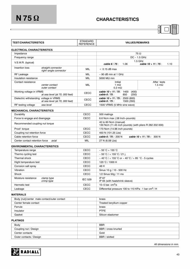
TEST/CHARACTERISTICS STANDARDREFERENCE VALUES/REMARKS
ELECTRICAL CHARACTERISTICSImpedance 75Frequency range DC -- 1.5 GHz
V.S.W.R. (typical) 1.5 GHzcable 6 / 75 : 1.06 cable 10 + 11 / 75 : 1.10
Insertion loss straight connectorright--angle connector MIL 0.15 dB max
RF Leakage MIL -- 90 dB min at 1 GHzInsulation resistance MIL 5000 M minContact resistance
center contactouter contact
MILInitial1 m0.2 m
After tests1.5 m
--
Working voltage in VRMSat sea level (at 70, 000 feet) CECC cable 10 + 11 / 75 : 1400 (400)
cable 6 / 75 : 850 (250)Dielectric withstanding voltage in VRMS
at sea level (at 70, 000 feet) CECC cable 10 + 11 / 75 : 2500 (600)cable 6 / 75 : 1500 (350)
RF testing voltage sea level CECC 1500 VRMS (5 MHz sine wave)
MECHANICAL CHARACTERISTICSDurability CECC 500 matings
Force to engage and disengage CECC 6.6 Ncm max (.58 Inch--pounds)
Recommended coupling nut torque 40 to 60 Ncm (manual)130 Ncm (11.45 inch pounds) (with pliers R 282 202 000)
Proof torque CECC 170 Ncm (14.96 inch pounds)
Coupling nut retention force CECC 450 N (101.25 Lbs)
Cable retention force CECC cable 6 / 75 : 200 N cable 10 + 11 / 75 : 300 N
Center contact retention force axial MIL 27 N (6.08 Lbs)
ENVIRONMENTAL CHARACTERISTICSTemperature range CECC -- 55_C + 155_C
Thermo cycling test CECC -- 55_C / + 155_C / 21 j.
Thermal shock CECC -- 40_C / + 155_C or -- 40_C / + 85 _C - 5 cycles
Hight temperature test CECC 125_C / 1000 H
Corosion salt spray CECC 48 H
Vibration CECC Sinus 10 g / 10 - 500 Hz
Shock CECC 1/2 Sinus 50g / 11 ms
Moisture resistance clamp typecrimp type IEC 529 IP 67
IP 65 (with heatshrink sleeve)
Hermetic test CECC 10--5 bar. cm3/s
Leakage CECC Differential pressure 100 to 110 KPa : 1 bar cm3 / H
MATERIALS
Body (nut)/center male contact/outer contact brass
Center female contact Treated beryllium copper
Ferrule brass
Insulator PTFE
Gasket Silicon elastomer
PLATINGS
Body BBR
Coupling nut / Design BBR / cross knurled
Center contacts Gold
Outer contacts / Design BBR / slotted
All dimensions in mm.
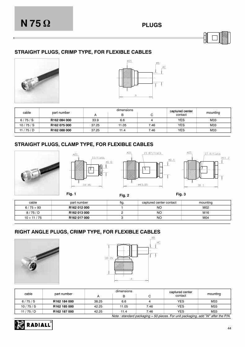
Fig. 1 Fig. 2
PLUGS
Fig. 3
N 75
44
STRAIGHT PLUGS, CRIMP TYPE, FOR FLEXIBLE CABLES
cable part numberdimensions captured center mountingcable part number
A B Ccaptured center
contactmounting
6 / 75 / S R162 084 000 33.9 6.6 4 YES M33
10 / 75 / S R162 075 000 37.25 11.05 7.46 YES M33
11 / 75 / D R162 088 000 37.25 11.4 7.46 YES M33
STRAIGHT PLUGS, CLAMP TYPE, FOR FLEXIBLE CABLES
cable part number fig. captured center contact mounting
6 / 75 + 93 R162 012 000 1 NO M02
8 / 75 / D R162 013 000 2 NO M16
10 + 11 / 75 R162 017 000 3 NO M04
RIGHT ANGLE PLUGS, CRIMP TYPE, FOR FLEXIBLE CABLES
cable part numberdimensions captured center mountingcable part number
A B Ccaptured center
contact mounting
6 / 75 / S R162 184 000 38.25 6.6 4 YES M33
10 / 75 / S R162 185 000 42.25 11.05 7.46 YES M33
11 / 75 / D R162 187 000 42.25 11.4 7.46 YES M33Note : standard packaging = 50 pieces. For unit packaging, add ”W” after the P/N.

Fig. 1 Fig. 2
PLUGS AND JACKS
Fig. 3
N 75
45
RIGHT ANGLE PLUGS, CLAMP TYPE, FOR FLEXIBLE CABLES
cable part number dimensions A captured center contact mounting
6 / 75 + 93 R162 162 000 6.5 YES M16
10 + 11 / 75 R162 168 000 11.2 YES M16
STRAIGHT JACKS, CRIMP TYPE, FOR FLEXIBLE CABLES
cable part numberdimensions captured center mountingcable part number
A B Ccaptured center
contactmounting
6 / 75 / S R162 239 000 36.6 6.6 4 YES M33
10 / 75 / S R162 241 000 40.6 11.05 7.46 YES M33
11 / 75 / D R162 243 000 40.6 11.4 7.46 YES M33
STRAIGHT JACKS, CLAMP TYPE, FOR FLEXIBLE CABLES
cable part number fig. captured centercontact mounting
6 / 75 + 93 / S R162 212 000 1 NO M02
8 / 75 / D R162 213 000 2 NO M16
10 + 11 / 75 R162 217 000 3 NO M04Note : standard packaging = 50 pieces. For unit packaging, add ”W” after the P/N.

Fig. 1 Fig. 2
JACKSN 75
46
SQUARE FLANGE STRAIGHT JACKS, CLAMP TYPE, FOR FLEXIBLE CABLES
cable part numberdimensions captured mounting panelcable part number
A B Ccaptured
center contactmounting panel
6 / 75 + 93 / S R162 262 000 34.9 6.6 11 NO M02 P03
10 + 11 / 75 R162 267 000 38.5 11.2 17.4 NO M04 P03
STRAIGHT BULKHEAD JACKS, CRIMP TYPE, FOR FLEXIBLE CABLES
cable part numberdimensions captured center mounting panelcable part number
A Bcaptured center
contactmounting panel
6 / 75 / S R162 335 000 6.6 4 YES M33 P01
10 / 75 / S R162 336 000 11.05 7.46 YES M33 P01
11 / 75 / D R162 339 000 11.4 7.46 YES M33 P01
STRAIGHT BULKHEAD JACKS, CLAMP TYPE, FOR FLEXIBLE CABLES
cable part number fig captured center mounting panelcable part number fig. captured centercontact mounting panel
6 / 75 + 93 / S R162 328 000 1 NO M02 P01
10 + 11 / 75 R162 332 000 2 NO M04 P01Note : standard packaging = 50 pieces. For unit packaging, add ”W” after the P/N.
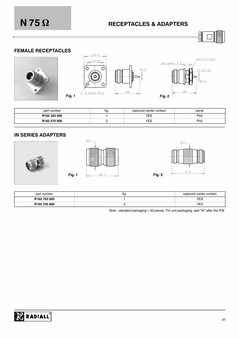
Fig. 1 Fig. 2
RECEPTACLES & ADAPTERS
Fig. 1 Fig. 2
N 75
47
FEMALE RECEPTACLES
part number fig. captured center contact panel
R162 403 000 1 YES P04
R162 570 000 2 YES P02
IN SERIES ADAPTERS
part number fig. captured center contact
R162 703 000 1 YES
R162 705 000 2 YES
Note : standard packaging = 50 pieces. For unit packaging, add ”W” after the P/N.

COAXIAL BETWEEN SERIES ADAPTERS
* For Push--on adapters, please ask for D1 036 DE catalog. Numerous other models for panel mount also currently availableUpon request
N
48
Ask for our full detailed catalog of COAXIAL BETWEEN SERIES ADAPTERS 50 & 75 * : D1 191 CE.
InterfaceSMA SMA 3.5 SMB SMC FME
InterfaceMale Female Male Female Male Female Male Female Male
N MaleR191 325 000R191 325 500(SMA Push--on)
R191 329 000R191 329 500(SMA Push--on)
R191 324 000 R191 328 000 R191 233 000 R191 141 000
N Female R191 327 000 R191 331 000 R191 326 000 R191 330 000 R191 236 000(flange) R191 239 000 R191 143 000 R191 147 000 R191 042 000
InterfaceBNC N 75 / BNC 75 TNC N 75 / 1.6 / 5.6 (75 ) DIN 7/16
InterfaceMale Female Male Female Male Female Male Female Male Female
N MaleR191 417 000R191 417 500(BNC Push--on)
R191 421 000R191 421 500(BNC Push--on)
R192 417 000 R192 421 000 R191 513 000 R192 775 000(screw-on)
R192 777 000(screw-onsnap-on)
R191 721 000 R191 720 000
N Female R191 419 000 R191 422 000(bulkhead)
R192 419 000 R192 418 000 R191 511 000 R191 514 000(flange)
R192 770 000(screw-on)
R192 771 000(screw-onsnap-on)
R191 722 000 R191 723 000
InterfaceC LC UHF HN
N18 / PC 7InterfaceMale Female Male Female Male Female Male Female
N18 / PC 7(18 GHz)
N Male R191 703 000 R191 731 000 R191 025 000Measurement
N Female R191 705 000 R191 708 000(flange) R191 745 000 R191 741 000 R191 733 000 R191 737 000 R191 027 000
Measurementkit (M + F)
R191 094 000

Joule effect soldering device
TOOLING
Compliant with European standards n_ 89/336/CEE and 73/23/CEE (electromagnetic compatibility and low voltage)
It allows to solder :
-- center contacts and bodies to semi--rigid cables,-- center contacts to flexible cables-- solder pot receptacles.
P/N of the soldering device : R282 800 000 (80 W--shown above)R282 800 001 (250 W).
Please ask for our leaflet about Joule effect soldering deviceD1 035 DE.
Radiall recommends to always carry out soldering operations in wellventilated areas and to make use of fume extraction equipment.Our fume extraction device complies also with Europeanstandards n_ 89/336/CEE , 89/392/CEE and 73/23/CEE.Its flow is adjustable up to 240m3 /h and it uses active coal filter.P/N of the fume extraction device : R282 803 000.
Fume extraction device
N
49

TOOLINGN
50
KIT : STRIPPING + CRIMPING CABLES 5 / 50 S + D AND 6 / 75 + 93 S + D
Part number R282124000
Inside the box, every part number can be ordered separately.

TOOLINGN
51
KIT : STRIPPING + CRIMPING CABLES 10 + 11 / 50 + 75 S + D
Part number R282124100
Inside the box, every part number can be ordered separately.

*
TOOLING
MIL CRIMP TOOL (MIL 22520/05--01) (DIES NOT INCLUDED)
DIES
N
52
RADIALL CRIMP TOOLS (DIES INCLUDED)
* Square crimping print.
Part number R282293000
Part number Cable group
R282 235 003 2.6/50 S 3.25 2.67
R282 235 011 5/50 S -- 5/50 D 5.41 1.73
R282 235 013 6/75 S 6.48 1.73
R282 235 037 2.6/50 D 7.97 3.84
R282 235 116 10/50 D -- 10.3/50 S-- 11/50 D 10.54 2.54
R282 235 166 15.2/50 S 15.49
TOOLINGN
53
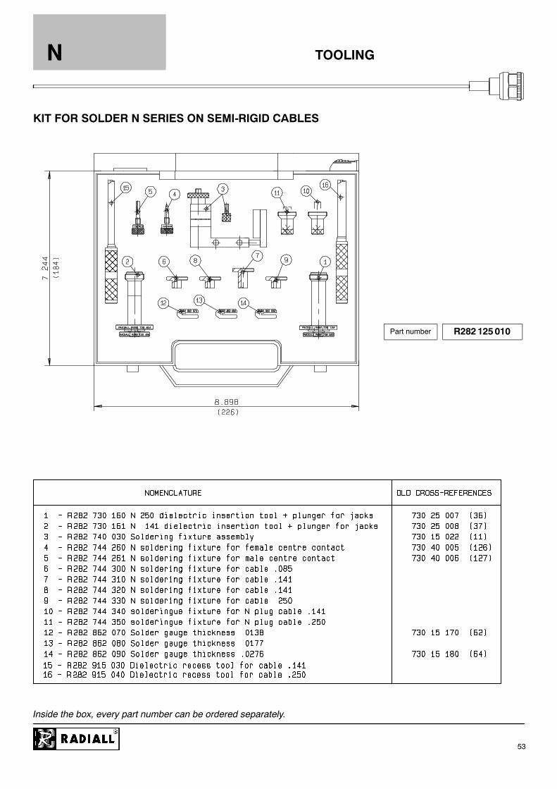
KIT FOR SOLDER N SERIES ON SEMI-RIGID CABLES
Part number R282125010
Inside the box, every part number can be ordered separately.

TOOLINGN
54
KIT : STRIPPING .125 (3.17) + CONING FOR .085” SEMI-RIGID CABLE
Part number R282114125
Inside the box, every part number can be ordered separately.

TOOLINGN
55
KIT : STRIPPING .177 (4.5) + CONING FOR .141” SEMI-RIGID CABLE
Part number R282114168
Inside the box, every part number can be ordered separately.
TOOLINGN
56
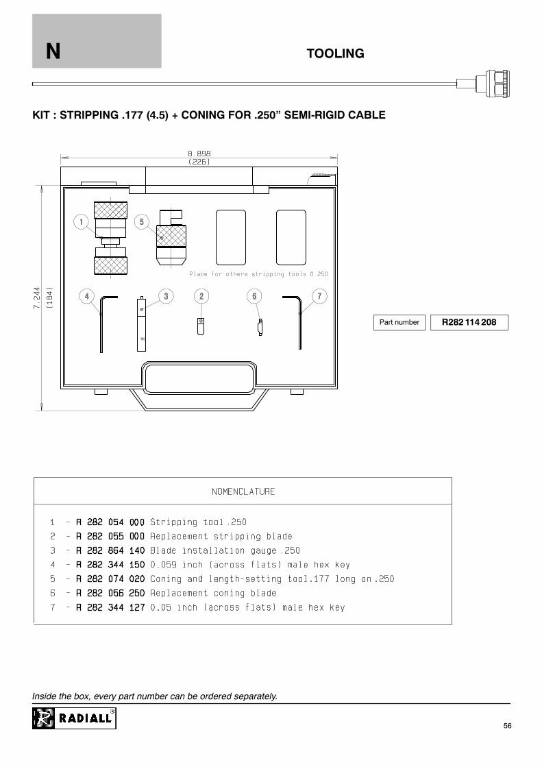
KIT : STRIPPING .177 (4.5) + CONING FOR .250” SEMI-RIGID CABLE
Part number R282114208
Inside the box, every part number can be ordered separately.

TOOLINGN
57
KIT : BENDING OF SEMI--RIGID CABLES
Part number R282102000
Inside the box, every part number can be ordered separately.
TOOLING
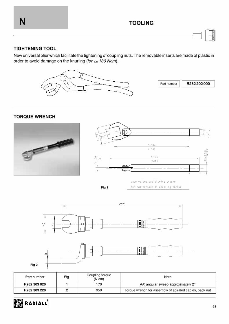
Newuniversal plier which facilitate the tightening of coupling nuts. The removable inserts aremade of plastic inorder to avoid damage on the knurling (for' 130 Ncm).
TORQUE WRENCH
Fig 2
Fig 1
N
58
TIGHTENING TOOL
Part number R282202000
Part number Fig Coupling torque NotePart number Fig. Coupling torque(N cm) Note
R282 303 020 1 170 AA’ angular sweep approximately 2_
R282 303 220 2 950 Torque wrench for assembly of spiraled cables, back nut

TOOLS FOR FLEXIBLE CABLESN
59
MATCHING P/N WITH CRIMP TOOLS
Cable strip dimensions Center contact Ferrule*
P/N Mountinga b c Hex. Crimp tool Hex.
Standard crimptools P/N
(dies included)
MIL Crimp toolR 282 293 000+ dies P/N
R 161 071 000M09
4 135 41 R 282 223 000 R 282 235 011
R 161 072 000M09
4.5 8 14-- -- 5.41 R 282 223 000 R 282 235 011
R 161 075 000 8 14
R 161 075 060R 161 076 000
M10 59 15
2.54 R 282 231 000 10.54 R 282 231 000 R 282 235 116
R 161 079 220 M11 4 11 17 -- -- 15.49 -- R 282 235 166Y1668 DANIELS
R 161 082 000R 161 082 200 M12R 161 082 200R 161 083 000
M124.5 8 14 1.73 R 282 223 000 5.41 R 282 223 000 R 282 235 011
R 161 083 137 M24
R 161 088 000 M105 8 14 2 54 R 282 231 000 10 54 R 282 231 000 R 282 235 116
R 161 088 137 M245 8 14 2.54 R 282 231 000 10.54 R 282 231 000 R 282 235 116
R 161 181 000M18 3 5 7 18
3.25 R 282 211 000 R 282 235 003
R 161 181 300M18 3.5 7 18 -- --
3.84 R 282 271 000 R 282 235 037
R 161 182 000R 161 182 200R 161 183 000
M183.5 7 18 -- -- 5.41 R 282 223 000 R 282 235 011
R 161 183 137 M25
R 161 184 000 M18 2.5 10 22.5 -- --
R 161 185 000 M20 4.5 8 15 2.54 R 282 231 000
R 161 184 036M18 2 5
16.7 29.210 54 R 282 231 000 R 282 235 116
R 161 186 000M18 2.5
8 22.5-- -- 10.54 R 282 231 000 R 282 235 116
Y116 DANIELS
R 161 187 000 M20 4.5 8 15 2.54 R 282 231 000
R 161 186 137 M18 2.5 10 22.5 -- --
R 161 188 200 M19 9.5 15 30 -- -- 15.49 -- R 282 235 166Y1168 DANIELS
R 161 237 000R 161 238 000 M12 4.5 8 14 1.73 R 282 223 000 5.41 R 282 223 000 R 282 235 011
R 161 241 000R 161 243 000 M10 5 8 14 2.54 R 282 231 000 10.54 R 282 231 000 R 282 235 116
R 161 281 000M09
4 13
R 161 281 300M09
4.5 8 14-- --
5 41 R 282 223 000 R 282 235 011R 161 282 000R 161 283 000 M12 4.5 8 14 1.73 R 282 223 000
5.41 R 282 223 000 R 282 235 011
R 161 286 000R 161 286 200 M10 5 8 14 2.54 R 282 231 000 10.54 R 282 231 000 R 282 235 116
R 161 309 000R 161 309 200 M09 4 13 -- -- 5.41 R 282 223 000 R 282 235 011
* To crimp the ferrule you can choose : either one standard crimp tool with included dies.or the MIL crimp tool and its separated dies.

TOOLS FOR FLEXIBLE CABLESN
60
MATCHING P/N WITH CRIMP TOOLS
Cable strip dimensions Center contact Ferrule*
P/N Mountinga b c Hex. Crimp tool Hex.
Standard crimptools P/N
(dies included)
MIL Crimp toolR 282 293 000+ dies P/N
R 161 311 200R 161 311 300 M09 -- --
R 161 329 130R 161 329 000R 161 329 200
M124.5 8 14
1.73 R 282 223 0005.41 R 282 223 000 R 282 235 011
R 161 331 000 M10 8 14 2.54 R 282 231 000
R 161 331 060 M11 5 9 15 -- -- 10.54 R 282 231 000 R 282 235 116
R 161 331 200 M10 8 14 2.54 R 282 231 000
R 161 331 400 M11 4 11 17 -- -- 15.49 -- R 282 235 166Y1168 DANIELS
R 162 075 000 5 8 14 10.54 R 282 231 000 R 282 235 116Y116 DANIELS
R 162 084 000 8 14 6.48 R 282 223 000 R 282 235 013
R 162 088 0004 5
7.5 17 10.54 R 282 231 000 R 282 235 116Y116 DANIELS
R 162 184 0004.5
8 14 6.48 R 282 223 000 R 282 235 013
R 162 185 000 M33 7 5 17 1 73 R 282 223 000 10 54 R 282 231 000 R 282 235 116R 162 185 000R 162 187 000 M33 7.5 17 1.73 R 282 223 000 10.54 R 282 231 000 R 282 235 116
Y116 DANIELS
R 162 239 000 5 8 14 6.48 R 282 223 000 R 282 235 013
R 162 241 000 4 5 7 5 17 10 54 R 282 231 000 R 282 235 116R 162 241 000R 162 243 000 4.5 7.5 17 10.54 R 282 231 000 R 282 235 116
Y116 DANIELS
R 162 335 000 5 8 14 6.48 R 282 223 000 R 282 235 013
R 162 336 000 4 5 7 5 17 10 54 R 282 231 000 R 282 235 116R 162 336 000R 162 339 000 4.5 7.5 17 10.54 R 282 231 000 R 282 235 116
Y116 DANIELS
R 280 651 030R 280 651 230
M27 3 8 23 5-- -- 5.41 R 282 223 000 R 282 235 011
R 280 663 030R 280 664 030
M27 3 8 23.5-- -- 10.54 R 282 231 000 R 282 235 116
Y116 DANIELS
* To crimp the ferrule you can choose : either one standard crimp tool with included dies.or the MIL crimp tool and its separated dies.

P01 P03
P05 P06
P07 P09
P10 P11
P02
P04
P08
P12
PANEL DRILLINGN
61
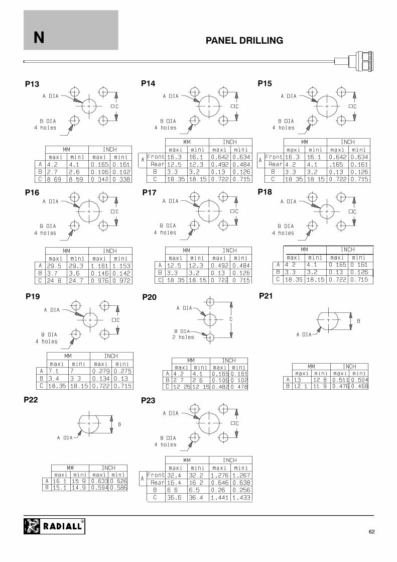
P14P13
P16
P15
P18P17
P19 P20 P21
P22 P23
PANEL DRILLINGN
62

ASSEMBLY INSTRUCTIONS
M 01
1
2
3
4
11
N
63
CONNECTORSStripping length
CONNECTORSa b c d e
R161 004 000R161 252 000R161 321 000R161 322 000
42 8 2 4
R161 325 000 7.5 1
1.1 Slide clamp nut onto cable.1.2 Strip the cable.1.3 Cut the jacket (2 slots) appart if necessary.
2.1 Slide the clamp braid sleeve between cable dielectric and braid2.2 Cut the braid flush with the clamp braid sleeve.2.3 Slide the insulator.
3.1 Solder the cable inner conductor into center contact.3.2 Slide the back nut over the clamp assembly.
4.1 Mount the gasket into the connector.4.2 Screw sub--assembly into the connector body.
(recommended coupling torque 13.27 in.lb -- 150 Ncm).
ASSEMBLY INSTRUCTIONS
M 02
1
2
3
4
b
a
c
11
N
64
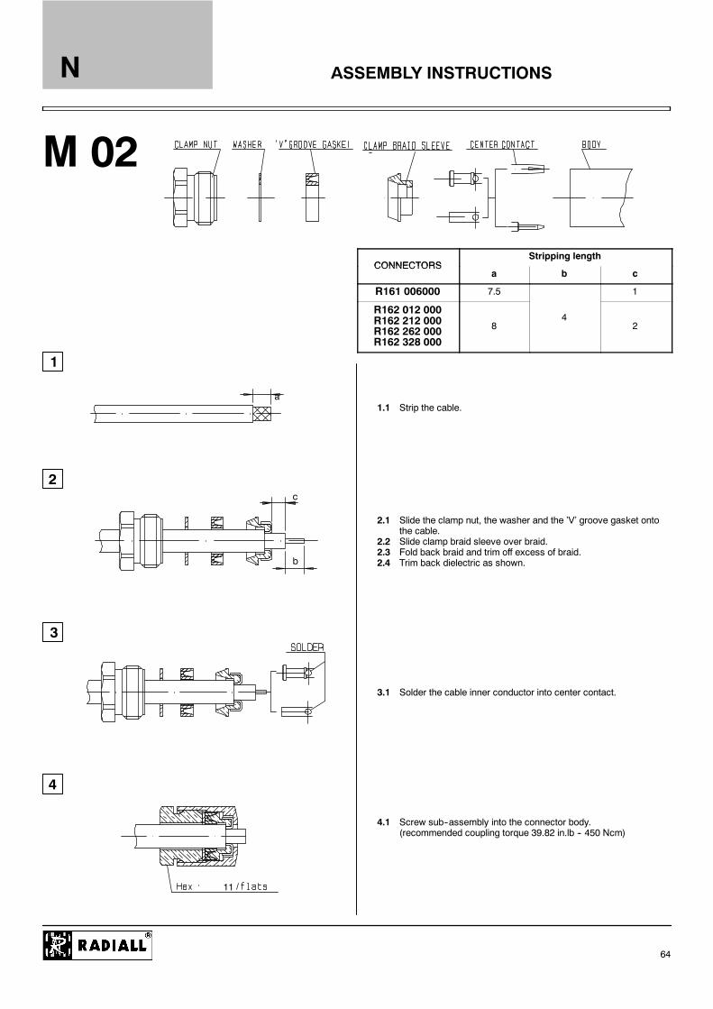
CONNECTORSStripping length
CONNECTORSa b c
R161 006000 7.5 1
R162 012 000R162 212 000R162 262 000R162 328 000
84
2
1.1 Strip the cable.
2.1 Slide the clamp nut, the washer and the ’V’ groove gasket ontothe cable.
2.2 Slide clamp braid sleeve over braid.2.3 Fold back braid and trim off excess of braid.2.4 Trim back dielectric as shown.
3.1 Solder the cable inner conductor into center contact.
4.1 Screw sub--assembly into the connector body.(recommended coupling torque 39.82 in.lb -- 450 Ncm)

ASSEMBLY INSTRUCTIONS
M 03
1
2
3
4
11
c
N
65
CONNECTORSStripping length
CONNECTORSa b c
R161 010 000 2
R161 206 000R161 256 000
4 7.51
1.1 Strip the cable.
2.1 Slide the clamp nut, the washer and the ’V’ groove gasket ontothe cable.
2.2 Slide clamp braid sleeve over braid.2.3 Fold back braid and trim off excess of braid.2.4 Trim back dielectric as shown.
3.1 Slide the washer and the insulator onto the dielectric.3.2 Solder the cable inner conductor into center contact.
4.1 Screw sub--assembly into the connector body.(recommended coupling torque 39.83 in.lb -- 450 cm).
ASSEMBLY INSTRUCTIONS
M 04
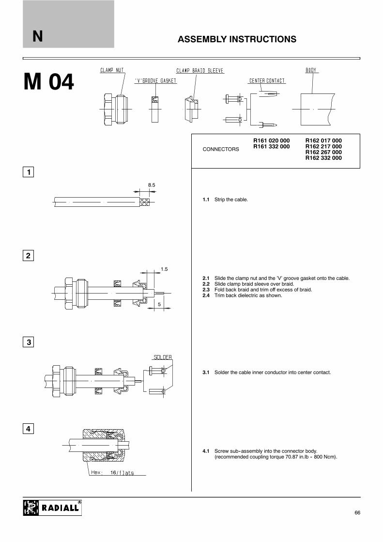
CONNECTORS
1
2
3
4
R161 020 000R161 332 000
R162 017 000R162 217 000R162 267 000R162 332 000
5
8.5
1.5
16
N
66
1.1 Strip the cable.
2.1 Slide the clamp nut and the ’V’ groove gasket onto the cable.2.2 Slide clamp braid sleeve over braid.2.3 Fold back braid and trim off excess of braid.2.4 Trim back dielectric as shown.
3.1 Solder the cable inner conductor into center contact.
4.1 Screw sub--assembly into the connector body.(recommended coupling torque 70.87 in.lb -- 800 Ncm).

ASSEMBLY INSTRUCTIONS
M 05
1
2
3
4
CONNECTORSR161 022 000R161 220 000R161 270 000
5
8.5
1.5
16
N
67
1.1 Strip the cable.
2.1 Slide the clamp nut, the washer and the ’V’ groove gasket ontothe cable.
2.2 Slide clamp braid sleeve over braid.2.3 Fold back braid and trim off excess of braid.2.4 Trim back dielectric as shown.
3.1 Mount washer and rear insulator.3.2 Solder the cable inner conductor into center contact.
4.1 Mount front insulator.4.2 Screw sub--assembly into the connector body.
(recommended coupling torque 70.87 in.lb -- 800 Ncm).
ASSEMBLY INSTRUCTIONS
M 06
1
2
3
4
a
11
N
68
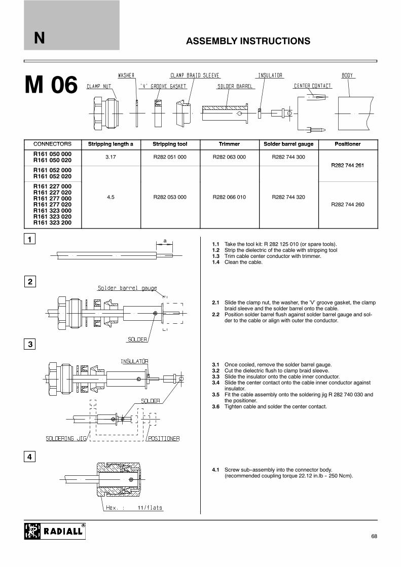
CONNECTORS Stripping length a Stripping tool Trimmer Solder barrel gauge PositionerCONNECTORS Stripping length a Stripping tool Trimmer Solder barrel gauge Positioner
R161 050 000R161 050 020 3.17 R282 051 000 R282 063 000 R282 744 300
R282 744 261R161 052 000R161 052 020
R282 744 261
R161 227 000R161 227 020R161 277 000R161 277 020R161 323 000R161 323 020R161 323 200
4.5 R282 053 000 R282 066 010 R282 744 320R282 744 260
1.1 Take the tool kit: R 282 125 010 (or spare tools).1.2 Strip the dielectric of the cable with stripping tool1.3 Trim cable center conductor with trimmer.1.4 Clean the cable.
2.1 Slide the clamp nut, the washer, the ’V’ groove gasket, the clampbraid sleeve and the solder barrel onto the cable.
2.2 Position solder barrel flush against solder barrel gauge and sol-der to the cable or align with outer the conductor.
3.1 Once cooled, remove the solder barrel gauge.3.2 Cut the dielectric flush to clamp braid sleeve.3.3 Slide the insulator onto the cable inner conductor.3.4 Slide the center contact onto the cable inner conductor against
insulator.3.5 Fit the cable assembly onto the soldering jig R 282 740 030 and
the positioner.3.6 Tighten cable and solder the center contact.
4.1 Screw sub--assembly into the connector body.(recommended coupling torque 22.12 in.lb -- 250 Ncm).

ASSEMBLY INSTRUCTIONS
M 07
1
2
3
4
b
a
N
69
CONNECTORS Stripping Stripping tool Trimmer Solder gauge Positioner Dielectric insertion DielectricCONNECTORS Strippinglength a Stripping tool Trimmer Solder gauge
[thickness b] Positioner Dielectric insertiontool + plunger
Dielectricrecess tool
R161 050 300 3.17 R282 051 000 R282 063 000 R282 862 090[0.7] without
R282 730 161R161 051 000
4 5
R282 053 000 R282 066 010 R282 862 070[0.35] R282 744 340
R282 730 161R282 915 030
R161 054 0004.5
R282 054 000 R282 074 020 R282 862 080[0.45) R282 744 350 R282 730 160 R282 915 040
1.1 Take the tool kit : R282 125 010 (or spare tools).1.2 Strip the dielectric of the cable with stripping tool cable.1.3 Trim the cable center conductor with trimmer1.4 Clean the cable.
2.1 Screw the positioner R282 744 261 onto the solderingjig R282 740 030.
2.2 Slide contact into positioner.2.3 Insert solder gauge between contact and cable2.4 Tighten and solder the contact.
3.1 After cooling remove cable assembly from the jig.3.2 Screw positioner into the connector.3.3 Slide cable into the connector until it bottoms against positioner.3.4 Tighten.3.5 Put 3 rings of solder around the cable and solder.
4.1 After cooling remove cable assembly from the jig.4.2 Screw female dielectric insert tool onto connector and cut the
excess of dielectric with the dielectric recess tool.4.3 Insert insulator with the dielectric plunger.
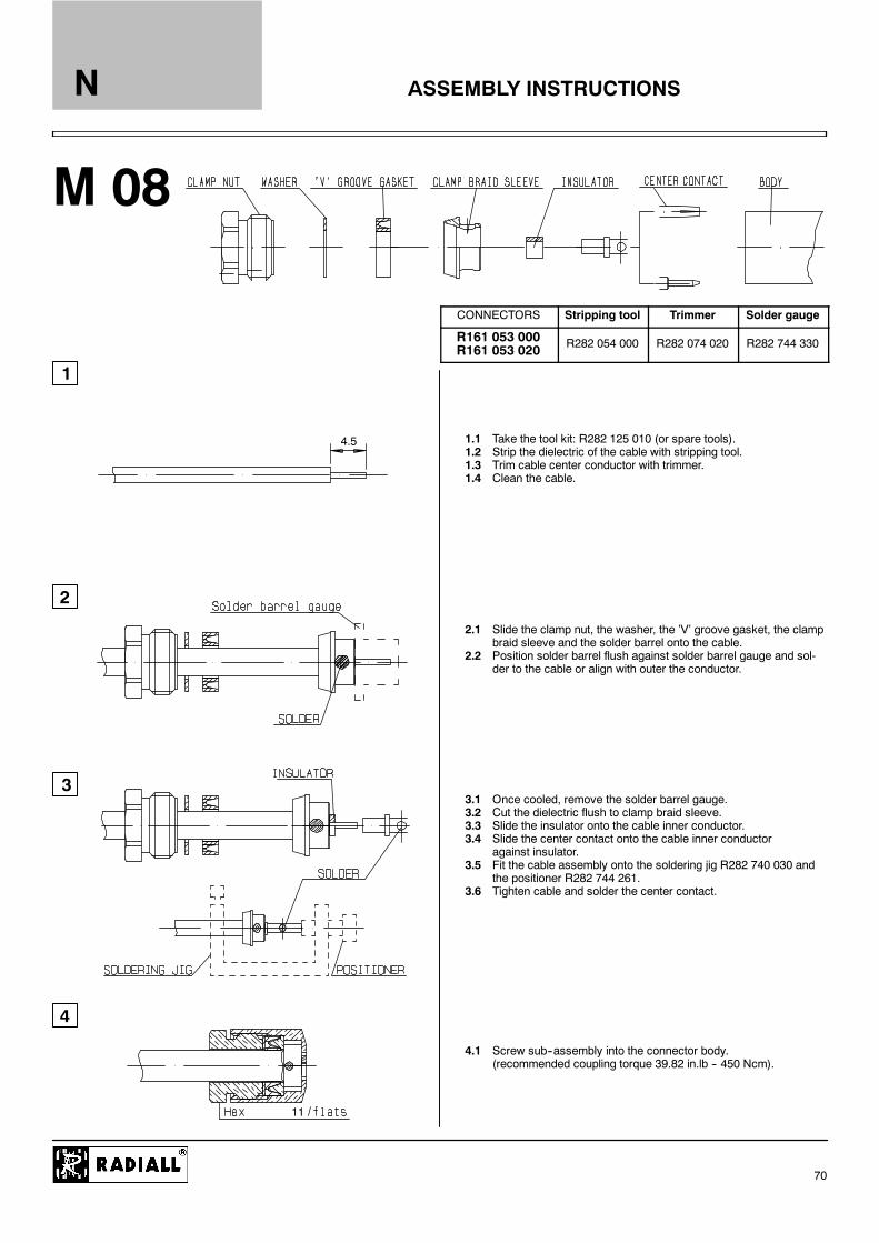
ASSEMBLY INSTRUCTIONS
M 08
1
2
3
4
4.5
11
N
70
CONNECTORS Stripping tool Trimmer Solder gauge
R161 053 000R161 053 020 R282 054 000 R282 074 020 R282 744 330
1.1 Take the tool kit: R282 125 010 (or spare tools).1.2 Strip the dielectric of the cable with stripping tool.1.3 Trim cable center conductor with trimmer.1.4 Clean the cable.
2.1 Slide the clamp nut, the washer, the ’V’ groove gasket, the clampbraid sleeve and the solder barrel onto the cable.
2.2 Position solder barrel flush against solder barrel gauge and sol-der to the cable or align with outer the conductor.
3.1 Once cooled, remove the solder barrel gauge.3.2 Cut the dielectric flush to clamp braid sleeve.3.3 Slide the insulator onto the cable inner conductor.3.4 Slide the center contact onto the cable inner conductor
against insulator.3.5 Fit the cable assembly onto the soldering jig R282 740 030 and
the positioner R282 744 261.3.6 Tighten cable and solder the center contact.
4.1 Screw sub--assembly into the connector body.(recommended coupling torque 39.82 in.lb -- 450 Ncm).

ASSEMBLY INSTRUCTIONS
M 09
1
2
3
4
ad
c
b
N
71
Stripping length Crimping toolCONNECTORS
a b c d Dies included MIL standard R282 293 000(M22520/5--01) + Dies Center contact
R161 071 000R161 281 000R161 309 000R161 309 200
4 9 13
R282 223 000 R282 235 011
R282 223 000Hex : 1.73
R161 072 000R161 281 300R161 311 200R161 311 300
4.5 9.5 14 8
R282 223 000Hex : 5.41
R282 235 011(M22520/5--11)
1.1 Slide the ferrule onto the cable.1.2 Strip the cable.
2.1 Fan the braid.2.2 Slide the braid clamp and insulator between the dielectric and the
braid.2.3 Slide on center contact until it bottoms against cable dielectric.2.4 Crimp center contact with crimping tool or solder.
3.1 Slide cable dielectric into the body while gently ginding the braidover the knurl.
3.2 Push until the dielectric clicks into position.3.3 Slide ferrule over the braid. (In direction F).
4.1 Crimp the ferrule with crimping tool.4.2 Cut the excess of braid.
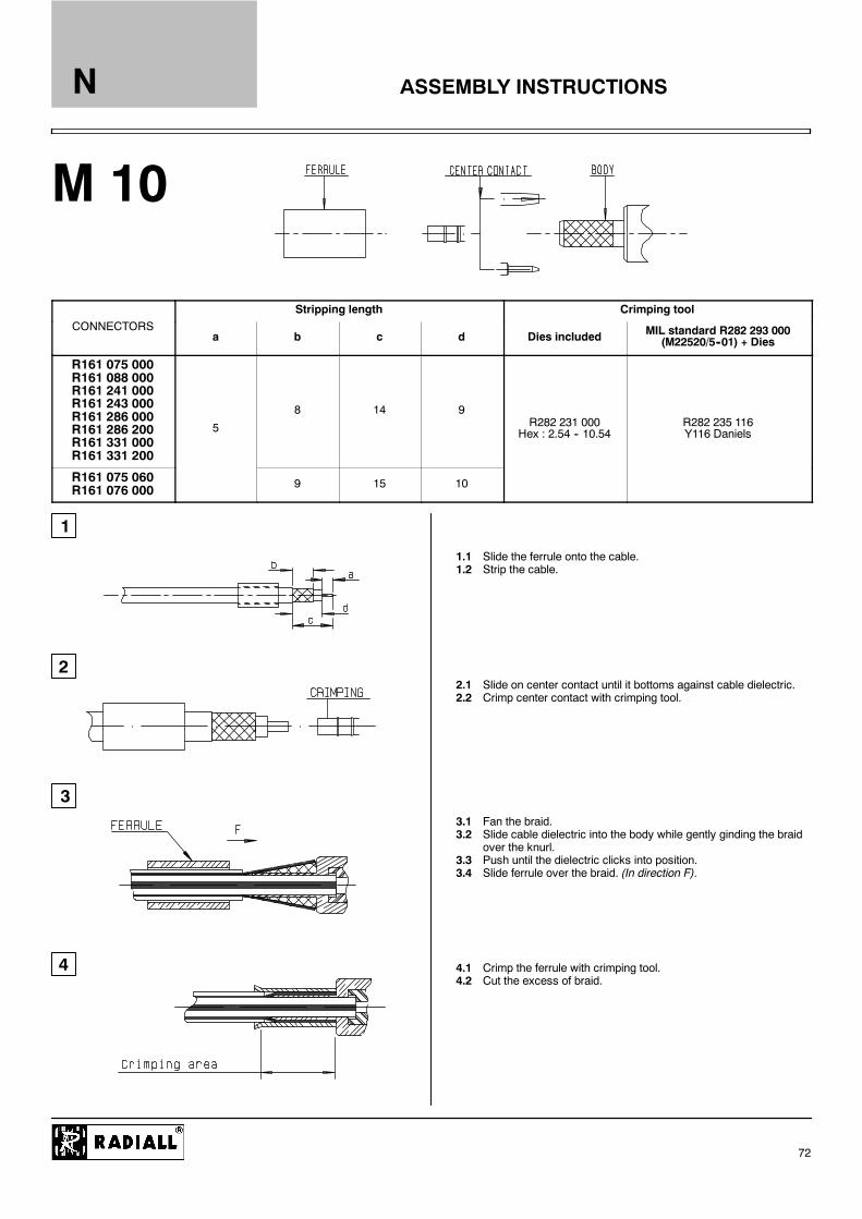
ASSEMBLY INSTRUCTIONS
M 10
1
2
3
4
N
72
Stripping length Crimping toolCONNECTORS
a b c d Dies included MIL standard R282 293 000(M22520/5--01) + Dies
R161 075 000R161 088 000R161 241 000R161 243 000R161 286 000R161 286 200R161 331 000R161 331 200
5
8 14 9R282 231 000
Hex : 2.54 -- 10.54R282 235 116Y116 Daniels
R161 075 060R161 076 000 9 15 10
1.1 Slide the ferrule onto the cable.1.2 Strip the cable.
2.1 Slide on center contact until it bottoms against cable dielectric.2.2 Crimp center contact with crimping tool.
3.1 Fan the braid.3.2 Slide cable dielectric into the body while gently ginding the braid
over the knurl.3.3 Push until the dielectric clicks into position.3.4 Slide ferrule over the braid. (In direction F).
4.1 Crimp the ferrule with crimping tool.4.2 Cut the excess of braid.
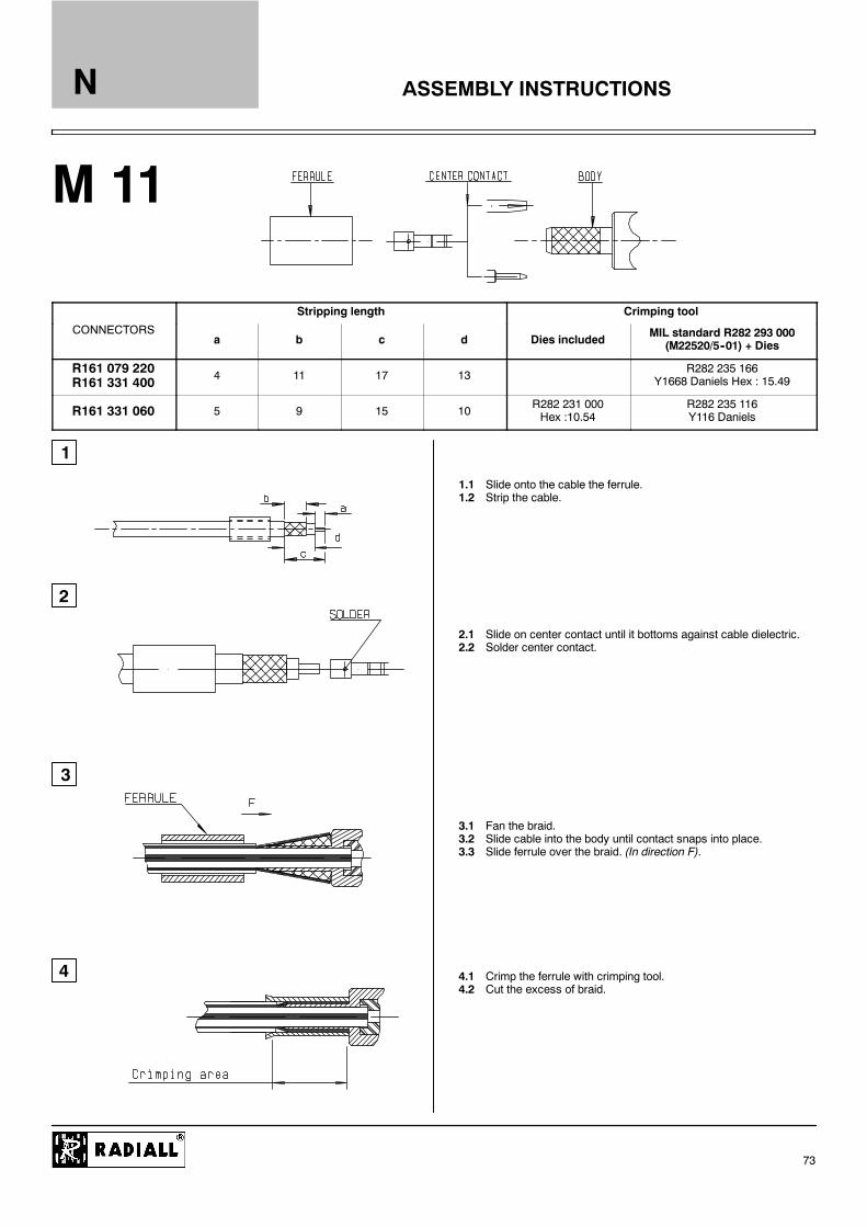
ASSEMBLY INSTRUCTIONS
M 11
1
2
3
4
N
73
Stripping length Crimping tool
CONNECTORSa b c d Dies included
MIL standard R282 293 000(M22520/5--01) + Dies
R161 079 220R161 331 400 4 11 17 13
R282 235 166Y1668 Daniels Hex : 15.49
R161 331 060 5 9 15 10R282 231 000Hex :10.54
R282 235 116Y116 Daniels
1.1 Slide onto the cable the ferrule.1.2 Strip the cable.
2.1 Slide on center contact until it bottoms against cable dielectric.2.2 Solder center contact.
3.1 Fan the braid.3.2 Slide cable into the body until contact snaps into place.3.3 Slide ferrule over the braid. (In direction F).
4.1 Crimp the ferrule with crimping tool.4.2 Cut the excess of braid.
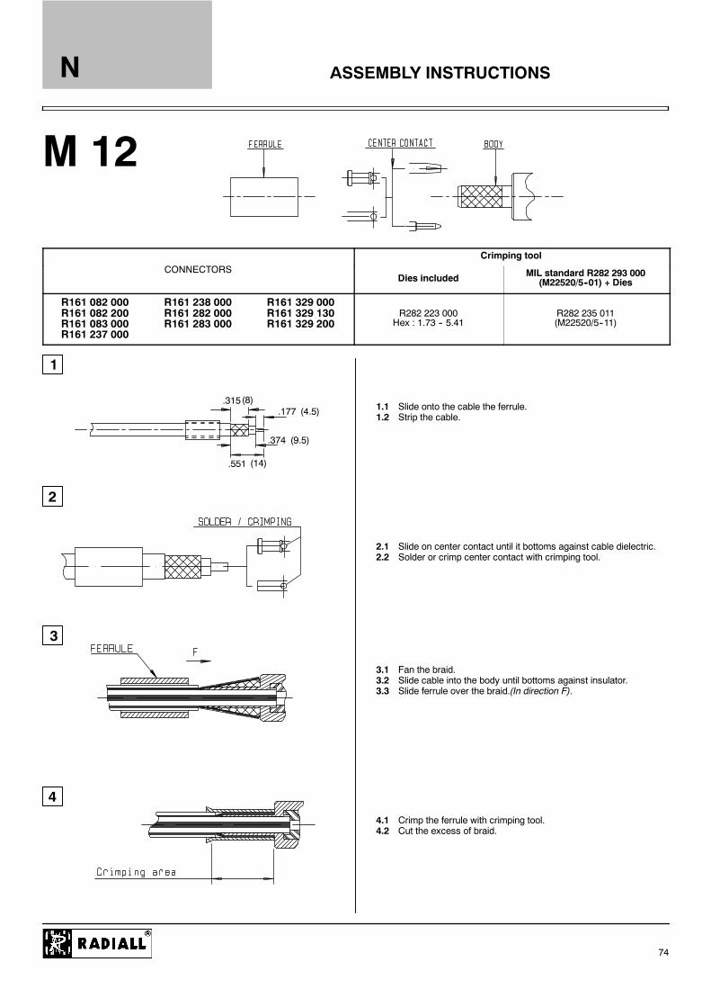
ASSEMBLY INSTRUCTIONS
M 12
1
2
3
4
.177.315
.551
.374
(4.5)(8)
(14)
(9.5)
N
74
Crimping toolCONNECTORS
Dies included MIL standard R282 293 000(M22520/5--01) + Dies
R161 082 000R161 082 200R161 083 000R161 237 000
R161 238 000R161 282 000R161 283 000
R161 329 000R161 329 130R161 329 200
R282 223 000Hex : 1.73 -- 5.41
R282 235 011(M22520/5--11)
1.1 Slide onto the cable the ferrule.1.2 Strip the cable.
2.1 Slide on center contact until it bottoms against cable dielectric.2.2 Solder or crimp center contact with crimping tool.
3.1 Fan the braid.3.2 Slide cable into the body until bottoms against insulator.3.3 Slide ferrule over the braid.(In direction F).
4.1 Crimp the ferrule with crimping tool.4.2 Cut the excess of braid.

ASSEMBLY INSTRUCTIONS
M 13
1
2
3
4
CONNECTORS R161 090 000
621.5
27.5
16
N
75
1.1 Strip the cable.1.2 Deburr outer conductor and make a .02 (0.5) chamfer on center
conductor.
2.1 Slide the clamp nut, the split ring and the gasket onto the cable.2.2 Slide clamp braid sleeve until it bottoms the outer conductor.
3.1 Mount rear insulator and center contact until it bottoms the clampbraid sleeve.
3.2 Solder the cable inner conductor into center contact.
4.1 Mount front insulator.4.2 Screw sub--assembly into the connector body.
(recommended coupling torque 70.8 in.lb -- 800 Ncm).

ASSEMBLY INSTRUCTIONS
M 14
1
2
3
4
CONNECTORS R161 091 000R161 291 150
525
30
21
N
76
1.1 Strip the cable.1.2 Cut the external conductor and dielectric on top of the wave as
shown.1.3 Deburr outer conductor and make a .04 (1) chamfer on center
conductor.
2.1 Slide the clamp nut until it bottoms the jacket.2.2 Assemble the two half ring in the bottom of the wave of the outer
conductor.
3.1 Slide back the clamp nut onto the two half ring.(In direction F).
4.1 Screw sub--assembly into the connector body.(recommended coupling torque 70.8 in.lb -- 800 Ncm).

ASSEMBLY INSTRUCTIONS
M 15
1
2
3
4
CONNECTORS R161 157 000
3.5
11.5
7
11
N
77
1.1 Strip the cable.
2.1 Slide the clamp nut, the washer and the gasket onto the cable.2.2 Slide clamp braid sleeve over braid.2.3 Fold back braid and trim off excess of braid.2.4 Trim back dielectric as shown.
3.1 Screw sub--assembly into the connector body.(recommended coupling torque 13.27 in.lb -- 150 Ncm).
3.2 Solder center contact.
4.1 Screw clamp nut into the body.
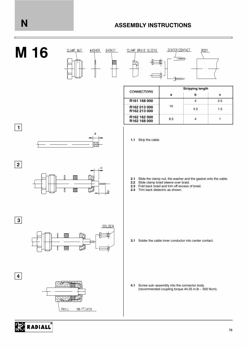
ASSEMBLY INSTRUCTIONS
M 16
1
2
3
4
b
a
c
16
N
78
CONNECTORSStripping length
CONNECTORSa b c
R161 168 000 4 2.5
R162 013 000R162 213 000
104.5 1.5
R162 162 000R162 168 000 8.5 4 1
1.1 Strip the cable.
2.1 Slide the clamp nut, the washer and the gasket onto the cable.2.2 Slide clamp braid sleeve over braid.2.3 Fold back braid and trim off excess of braid.2.4 Trim back dielectric as shown.
3.1 Solder the cable inner conductor into center contact.
4.1 Screw sub--assembly into the connector body.(recommended coupling torque 44.25 in.lb -- 500 Ncm).
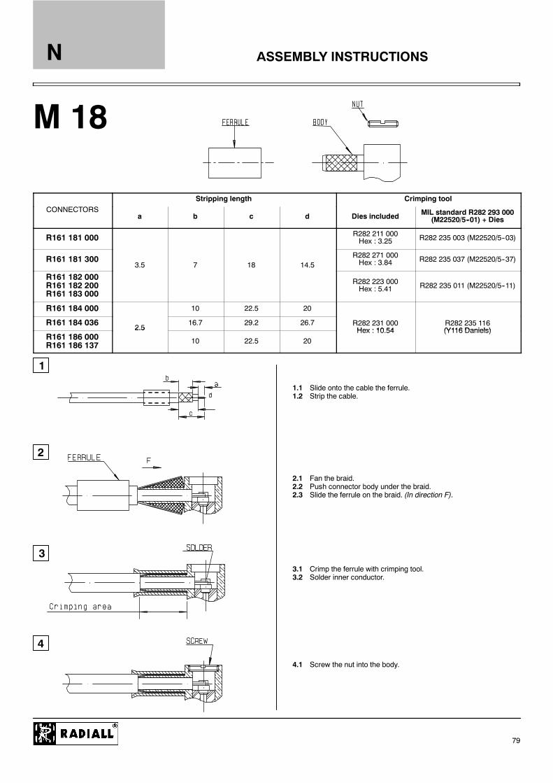
ASSEMBLY INSTRUCTIONS
M 18
1
2
3
4
N
79
Stripping length Crimping toolCONNECTORS
a b c d Dies included MIL standard R282 293 000(M22520/5--01) + Dies
R161 181 000 R282 211 000Hex : 3.25 R282 235 003 (M22520/5--03)
R161 181 3003.5 7 18 14.5
R282 271 000Hex : 3.84 R282 235 037 (M22520/5--37)
R161 182 000R161 182 200R161 183 000
R282 223 000Hex : 5.41 R282 235 011 (M22520/5--11)
R161 184 000 10 22.5 20
R161 184 0362.5
16.7 29.2 26.7 R282 231 000Hex : 10 54
R282 235 116(Y116 Daniels)
R161 186 000R161 186 137
2.5
10 22.5 20Hex : 10.54 (Y116 Daniels)
1.1 Slide onto the cable the ferrule.1.2 Strip the cable.
2.1 Fan the braid.2.2 Push connector body under the braid.2.3 Slide the ferrule on the braid. (In direction F).
3.1 Crimp the ferrule with crimping tool.3.2 Solder inner conductor.
4.1 Screw the nut into the body.

ASSEMBLY INSTRUCTIONS
M 19
1
2
3
4
N
80
Stripping length Crimping toolCONNECTORS
a b c d MIL standard R282 293 000(M22520/5--01) + Dies
R161 188 200 9.5 15 30 20.5 R282 235 166Y1168 Daniels Hex: 15.49
1.1 Slide onto the cable the ferrule.1.2 Strip the cable.
2.1 Fan the braid.2.2 Push connector body under the braid.2.3 Slide the ferrule on the braid. (In direction F).
3.1 Crimp the ferrule with crimping tool.3.2 Solder inner conductor.
4.1 Place the cap.4.2 Press cap flush or slightly bellow surface of body assembly.

ASSEMBLY INSTRUCTIONS
M 20
1
2
3
4
4.58
15
10.5
N
81
Crimping toolCONNECTORS
Dies included MIL standard R282 293 000(M22520/5--01) + Dies
R161 185 000R161 187 000 R282 231 000 Hex : 2.54 -- 10.54 R282 235 116
Y116 Daniels
1.1 Slide onto the cable the ferrule.1.2 Strip the cable.
2.1 Slide on the center contact until it bottoms against cable dielec-tric.
2.2 Crimp center contact, with crimping tool.
3.1 Fan the braid.3.2 Slide cable into the body until bottoms against insulator.3.3 Slide ferrule over the braid. (In direction F).
4.1 Crimp the ferrule with crimping tool.4.2 Cut the excess of braid.

ASSEMBLY INSTRUCTIONS
M 21
2
3
4
11
a
1
N
82
CONNECTORS Stripping length a Stripping tool Trimmer Solder gauge[thickness b] Positioner
R161 276 300R161 335 200 3.17 R282 051 000 R282 063 000 R282 744 300
R161 226 020R161 277 300R161 336 000R161 336 200 4.5
R282 053 000 R282 066 010
R282 862 090[0.7]
R282 744 310
R161 278 300R161 337 200 R282 054 000 R282 074 020 R282 862 080
[0.45] R282 744 330
1.1 Take the tool kit : R282 125 010.1.2 Strip the dielectric of the cable with stripping tool.1.3 Trim the cable center conductor with trimmer.1.4 Clean the cable.1.5 Screw the reducer on the cable.
2.1 Screw the positioner R282 744 060 onto the soldering jigR282 740 030.
2.2 Slide contact into positioner.2.3 Insert solder gauge between contact and cable.2.4 Tighten and solder the contact.
3.1 After cooling remove cable assembly from the jig.3.2 Put positioner on the soldering jig.3.3 Slide cable into the reducer until it bottoms against positioner.3.4 Tighten.3.5 Put 3 rings of solder around the cable and solder.
4.1 After cooling remove cable assembly from the jig.4.2 Slide insulator into the center contact.4.3 Screw sub-assembly into the connector body.
(recommended coupling torque 13.27 in.lb -- 150 Ncm).

ASSEMBLY INSTRUCTIONS
M 22
1
2
3
N
83
CONNECTORS Stripping toolStripping length
CONNECTORS Stripping toola b c d e g h
R161 036 007R161 232 007R161 279 007R161 341 007
R282 010 030 4.5 17 18.8 8 13 16
R161 036 207R161 232 207R161 279 207R161 341 207
R282 010 040
7 5 20 5 21 5 10 19 21 22R161 037 020R161 232 407R161 279 407R161 341 407
R282 010 050
7.5 20.5 21.5 10 19 21 22
1.1 Mount the clamp nut and the gasket onto the cable.1.2 Strip the cable with stripping tool..
2.1 Screw the braid-clamp 1 onto the spiral braid of the cable.2.2 Tighten manualy.2.3 Flatten out the screening cable on the braid-clamp 1.
3.1 Cut the dielectric of the cable at the level of the braid-clamp 1.

ASSEMBLY INSTRUCTIONS
M 22
5
6
4
(flg)
N
84
CONNECTORS Stripping toolStripping length
CONNECTORS Stripping toola b c d e g h
R161 036 007R161 232 007R161 279 007R161 341 007
R282 010 030 4.5 17 18.8 8 13 16
R161 036 207R161 232 207R161 279 207R161 341 207
R282 010 040
7 5 20 5 21 5 10 19 21 22R161 037 020R161 232 407R161 279 407R161 341 407
R282 010 050
7.5 20.5 21.5 10 19 21 22
4.1 Screw the braid-clamp.(recommended coupling torque 70.8 in.lb -- 800 Ncm).
5.1 Slide the insulator 1 into the braid.5.2 Slide the center contact on the cable inner conductor against the
insulator-1.5.3 Solder the center contact on the cable then slide the insula-
tor-2 on it.
6.1 Slide the assembly onto the body.(recommended coupling torque 70.8 in.lb -- 800 Ncm).

ASSEMBLY INSTRUCTIONS
M 23
1
2
3
4
d
e f
N
85
CONNECTORS Stripping toolStripping length
CONNECTORS Stripping toola b c d e f
R161 177 007 R282 010 030 7.5 10 22.5 15 16
R161 177 207 R282 010 040 9 12 29 2021 20
R161 177 137 R282 010 050 10.5 14 33.5 2321 20
1.1 Strip the cable.1.2 Strip the cable inner conductor with stripping tool.
2.1 Slide the clamp nut and the gasket-1 onto the cable.2.2 Screw the clamp braid sleeve with the gasket-2 on to the spiral
braid of the cable.2.3 Tighten manualy.
3.1 Screw the clamp nut into the connector body.(recommended coupling torque 70.8 in.lb -- 800 Ncm).(The cable must not turn into the right angle body).
3.2 Solder the cable inner conductor into center contact.
4.1 Place the cap.4.2 Press fit the cap with a flat punch.
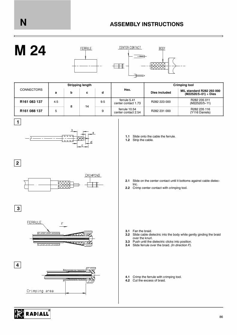
ASSEMBLY INSTRUCTIONS
M 24
1
2
3
4
d
N
86
Stripping length Crimping toolCONNECTORS
a b c dHex.
Dies included MIL standard R282 293 000(M22520/5--01) + Dies
R161 083 137 4.5
8 14
9.5 ferrule 5.41center contact 1.73 R282 223 000 R282 235 011
(M22520/5--11)
R161 088 137 58 14
9 ferrule 10.54center contact 2.54 R282 231 000 R282 235 116
(Y116 Daniels)
1.1 Slide onto the cable the ferrule.1.2 Strip the cable.
2.1 Slide on the center contact until it bottoms against cable dielec-tric.
2.2 Crimp center contact with crimping tool.
3.1 Fan the braid.3.2 Slide cable dielectric into the body while gently ginding the braid
over the knurl.3.3 Push until the dielectric clicks into position.3.4 Slide ferrule over the braid. (In direction F).
4.1 Crimp the ferrule with crimping tool.4.2 Cut the excess of braid.

ASSEMBLY INSTRUCTIONS
M 25
1
2
3
4
3.57
1815
N
87
Crimping tool
CONNECTORSDies included
MIL standard R282 293000
(M22520/5--01) + Dies
R161 183 137 R282 223 000Hex : 5.41
R282 235 011(M22520/5--11)
1.1 Slide the ferrule onto the cable.1.2 Strip the cable.
2.1 Fan the braid.2.2 Push connector body under the braid.2.3 Slide the ferrule on the braid. (In direction F).
3.1 Crimp the ferrule with crimping tool.3.2 Solder inner conductor.
4.1 Screw the nut into the body.

ASSEMBLY INSTRUCTIONS
M 26
1
2
3
4
58
21
16
N
88
Crimping toolCONNECTORS
Dies included MIL standard R282 293 000(M22520/5--01) + Dies
R161 186 137 R282 231 000Hex : 10.54
R282 235 116(Y116 Daniels)
1.1 Slide the ferrule onto the cable.1.2 Strip the cable.
2.1 Fan the braid.2.2 Push connector body under the braid.2.3 Slide the ferrule on the braid. (In direction F).
3.1 Crimp the ferrule with crimping tool.3.2 Solder inner conductor.
4.1 Place the cap.4.2 Press cap flush or slightly bellow surface of body assembly.

ASSEMBLY INSTRUCTIONS
M 27
1
2
4
3
6
5
20.53
23.5
N
89
Crimping tool
CONNECTORSDies included
MIL standard R282 293 000(M22520/5--01) + Dies
Torque wrench Recommended coupling torque
R280 651 030R280 651 230
R282 223 000Hex : 5.41
R282 235 011(M22520/5--11)
R282 303 220 950 N cmR280 663 030R280 664 030
R282 231 000Hex : 10.54
R282 235 116(Y116 Daniels)
R282 303 220 950 N.cm
1.11.2
2.12.22.3
3.1
4.14.2
5.1
6.1

ASSEMBLY INSTRUCTIONS
M 28
1
2
4
3
5
6
13
8
3
N
90
CONNECTORS Torque wrench Recommendedcoupling torque
R280 008 030 R280 303 220 950 N.cm
1.1
2.1
2.22.32.4
3.1
4.14.2
5.1
6.1

ASSEMBLY INSTRUCTIONS
M 29
1
2
4
3
5
6
13
8
3
N
91
CONNECTORS Torque wrench Recommendedcoupling torque
R280 017 030 R280 303 220 950 N.cm
1.1
2.1
2.22.32.4
3.1
4.14.2
5.1
6.1

ASSEMBLY INSTRUCTIONS
M 30
1
2
3
4
5
6
5.55
11.5
N
92
CONNECTORS Stripping tool Torque wrench Recommended coupling torque
R280 021 200 R282 010 030
R280 022 200 R282 010 050 R282 303 220 950 N.cm
R280 023 200 R282 010 040
1.11.21.3
2.12.2
3.1
4.14.2
5.1
6.1
6.2

ASSEMBLY INSTRUCTIONS
M 32
3
1
CONNECTORS R161 033 120WR161 231 120W
4
2
2 HALF RING
2 HALF RING
BUSHING
40
N
93
1.1 Strip the cable.1.2 Cut the external conductor and dielectric on top of the wave as
shown.1.3 Deburr outer conductor and make a .04 chamfer on center
conductor.
2.1 Slide the clamp nut until it bottoms the jacket2.2 Assemble the two half ring in the bottom of the wave of the outer
conductor.
3.1 Slide the bushing under the external conductor.3.2 Slide back the clamp nut onto the two half ring in direction F.
4.1 Screw sub--assembly into the connector body.(recommended coupling torque 70.8 in lb -- 800Ncm)

ASSEMBLY INSTRUCTIONS
M 33
3
1
4
2
d
N
94
stripping length center contact crimping tool ferrule crimping tool
CONNECTORSa b c d
hex.Dim. H dies included
MIL standardR282 293 000
(M22520/5--01) + diesdies included
MIL standardR282 293 000
(M22520/5--01) + dies
R162 084 000R162 184 000 4.5
8 149.5
1 73--6 48 R282 223 000 R282 235 013R162 239 000R162 335 000 5
8 149
1.73--6.48 R282 223 000 R282 235 013(M22520/5--13)
R162 075 000R162 088 000R162 185 000R162 187 000R162 241 000R162 243 000R162 336 000R162 339 000
4.5 7.5 17 12.5 1.73--10.54
R282 223 000 R282 235 011(M22520/5--11)
R282 231 000 R282 235 116(Y116 DANIELS)
1.1 Slide the ferrule onto the cable.1.2 Strip the cable
2.1 Slide center contact on until it bottoms against cable dielectric.2.2 Crimp the center contact.
3.1 Fan the braid.3.2 Slide the cable into the body until it bottoms against insulator.3.3 Slide the ferrule over the braid (In direction F).
4.1 Crimp the ferrule.4.2 Cut the excess of braid if necessary.

GROUPE
RG 6A/U 75 single core .028 (0,72) .185 (4,70) .263 (6,70) (D) .332 (8,43) .315 (8)/75 DRG 11A/U 75 7 X 0,40 .047 (1,20) .285 (7,25) .340 (8,64) (S) .405 (10,29) .394 (10)/75 SRG 58C/U 50 19 X 0,18 .035 (0,89) .116 (2,95) .150 (3,81) (S) .195 (4,95) .197 (5)/50 SRG 59B/U 75 single core .022 (0,57) .146 (3,71) .191 (4,85) (S) .242 (6,15) .236 (6)/75 SRG 62B/U 93 single core .025 (0,64) .146 (3,71) .191 (4,85) (S) .242 (6,15) .236 (6)/93 SRG 71B/U 93 single core .025 (0,64) .146 (3,71) .208 (5,28) (D) .245 (6,22) .236 (6)/93 DRG 141A/U 50 single core .039 (0,99) .116 (2,95) .146 (3,71) (S) .190 (4,83) .197 (5)/50 SRG 142B/U 50 single core .037 (0,94) .116 (2,95) .171 (4,34) (D) .195 (4,95) .197 (5)/50 DRG 174A/U 50 7 X 0,16 .019 (0,48) .060 (1,52) .088 (2,24 (S) .110 (2,79) .102 (2,6)/50 SRG 178B/U 50 7 X 0,10 .012 (0,30) .033 (0,84) .054 (1,37) (S) .071 (1,80) .079 (2)/50 SRG 179B/U 75 7 X 0,10 .012 (0,30) .063 (1,60) .083 (2,13) (S) .010 (2,54) .102 (2,6)/75 SRG 188A/U 50 7 X 0,18 .020 (0,51) .060 (1,52) .081 (2,06) (S) .110 (2,79) .102 (2,6)/50 SRG 212/U 50 single core .056 (1,41) .185 (4,70) .210 (5,34) (D) .331 (8,43) .315 (8)/50 DRG 213/U 50 7 X 0,75 .089 (2,25) .285 (7,25) .340 (8,64) (S) .405 (10,29) .394 (10)/50 SRG 214/U 50 7 X 0,75 .089 (2,25) .285 (7,25) .360 (9,14) (D) .425 (10,80) .433 (11)/50 DRG 216/U 75 7 X 0,40 .047 (1,20) .285 (7,25) .360 (9,15) (D) .425 (10,80) .433 (11)/75 DRG 217/U 50 single core .106 (2,69) .370 (9,40) .463 (11,76) (D) .545 (13,84) .551 (14)/50 DRG 218/U 50 single core .195 (4,95) .680 (17,27) .760 (19,30) (S) .870 (22,10) .866 (22)/50 SRG 316/U 50 7 x 0,17 .020 (0,51) .060 (1,52) .081 (2,06) (S) .098 (2,49) .102 (2,6)/50 SRD 316 50 7 x 0,17 .020 (0,51) .060 (1,52) .087 (2,22) (D) .110 (2,80) .102 (2,6)/50 DRG 400 50 19 x 0,2 .039 (1) .116 (2,95) .169 (4,30) (D) .197 (5) .197 (5)/50 DRG 393 50 7 x 0,8 .094 (2,4) .285 (7,25) .346 (8,80) (D) .390 (9,9) .394 (10)/50 DRG 401/U 50 single core .064 (1,63) .209 (5,31) ---- .250 (6,35) .250”RG 402/U 50 single core .036 (0,92) .117 (2,98) ---- .141 (3,58) .141”RG 405/U 50 single core .020 (0,51) .066 (1,68) ---- .087 (2,20) .085”
LMR 200 50 single core .044 (1,12) .116 (2,95) .144 (3,66) (S) .197 (5) .197 (5)/50 SLMR 400 50 single core .109 (2,77) .285 (7,24) .320 (8,13) (S) .405 (10,3) .405 (10,3)/50 SLMR 600 50 single core .176 (4,47) .455 (11,56) .490 (12,45) (S) .591 (15) .591 (15,2)/50 S
KX 3B 50 7 X 0,16 .019 (0,48) .059 (1,50) .088 (2,23) (S) .10 (2,54) .102 (2,6)/50 SKX 4 50 7 X 0,75 .089 (2,25) .285 (7,25) .340 (8,64) (S) .405 (10,29) .394 (10)/50 SKX 6A 75 7 X 0,20 .024 (0,60) .146 (3,70) .191 (4,85) (S) .240 (6,10) .236 (6)/75 SKX 8 75 7 X 0,40 .047 (1,20) .285 (7,25) .340 (8,64) (S) .405 (10,29) .394 (10)/75 SKX 13 50 7 X 0,75 .089 (2,25) .285 (7,25) .360 (9,14) (D) .425 (10,80) .433 (11)/50 DKX 14 50 single core .197 (5,00) .681 (17,30) .760 (19,30) (S) .870 (22,10) .866 (22)/50 SKX 15 50 19 X 0,18 .035 (0,89) .116 (2,95) .150 (3,81) (S) .195 (4,95) .197 (5)/50 SKX 21A 50 7 X 0,10 .012 (0,30) .034 (0,87) .054 (1,37) (S) .071 (1,80) .79 (2)/50 SKX 22A 50 7 X 0,18 .020 (0,51) .059 (1,50) .081 (2,06) (S) .098 (2,50) .102 (2,6)/50 SKX 22D 50 7 X 0,17 .020 (0,51) .059 (1,50) .098 (2,50) (D) .118 (3,00) .102 (2,6)/50 DKX 23 50 7 X 0,34 .040 (1,02) .116 (2,95) .171 (4,34) (D) .200 (5,10) .197 (5)/50 DKX 24 50 7 X 0,80 .094 (2,40) .285 (7,25) .360 (9,14) (D) .429 (10,90) .433 (11)/50 DKX 25 75 7 X 0,23 .028 (0,71) .146 (3,70) .176 (4,47) (S) .232 (5,90) .236 (6)/75 SKX 30 93 single core .025 (0,64) .146 (3,70) .191 (4,85) (S) .242 (6,15) .236 (6)/93 SKX 52 75 single core .025 (0,64) .146 (3,70) .185 (4,70) (S) .240 (6,10) .236 (6)/75 SKS 1 50 single core .020 (0,515) .066 (1,67) ---- .086 (2,18) .085”KS 2 50 single core .036 (0,915) .118 (3,00) ---- .140 (3,58) .141”KS 3 50 single core .064 (1,63) .210 (5,33) ---- .250 (6,35) .250”
(S) : 1 braid ; (D) : 2 braids
FLEXIBLE CABLES NF--C 93--550 / SEMI--RIGID CABLES NF--C 93--551
FLEXIBLE AND SEMI-RIGID CABLES MIL--C--17--F and LMR CABLES
CABLE DIMENSION REFERENCE CHARTThe following tables are presented as a convenient reference only. For detailed specifications, refer to the relevant standard or cablemanufacturer’s specifi-cations. All dimensions are nominal unless otherwise specified.
CABLECABLE
COREDIELECTRIC SCREEN JACKET
DIMENSIONS
Composition DIA nom.
IMPNOM.
inch (mm)/
HELIAX FSJ1-50A .075 (1,90) .185 (4,70) .252 (6,40) .291 (7,40) 1/4”/50 spiralHELIAX FSJ2-50 .110 (2,8) .275 (7) .375 (9,50) .415 (10,50) 3/8”/50 spiralHELIAX FSJ4-50B .142 (3,60) .342 (8,70) .480 (12,20) .520 (13,20) 1/2”/50 spiralHELIAX LDF5-50A .354 (9) .929 (23,6) 1.016 (25,8) 1.102 (28) 7/8”/50 annulat.GEDELEX 3,7/50 CCES - 1/2” .140 (3,56) .331 (8,40) .472 (12,00) .531 (13,50) 1/2”/50 spiralGEDELEX 2,3/50 CC - 1/4” .094 (2,40) .236 (6,00) .295 (7,50) .394 (10,00) 1/4”/50 annulat.HELIAX LDF4-50A .189 (4,80) .457 (11,60) .551 (14,00) .630 (16,00) 1/2”/50 annulat.GEDELEX 4,8/50 CCFP - 1/2” .189 (4,80) .468 (11,90) .543 (13,80) .650 (16,50) 1/2”/50 annulat.
CORRUGATED CABLES 50
ACOME P 1977 A (BULL approval) .085 (2,17) .242 (6,15) .325 (8,26) (D) .406 (10,30) EthernetBELDEN 9880 .085 (2,17) .247 (6,27) .315 (8,00) (D) .405 (10,28) EthernetFILOTEX 63227 .085 (2,17) .252 (6,40) .327 (8,30) (D) .406 (10,30) EthernetBICC H8 112 .085 (2,17) .250 (6,35) .326 (8,29) (D) .406 (10,30) EthernetPRECICABLE CY 120 .094 (2,40) .252 (6,40) .323 (8,20) (D) .406 (10,30) EthernetTIMES A A4779 .087 (2,20) .242 (6,14) .370 (9,40) (D) .409 (10,40) Ethernet
ETHERNET CABLES 50
DIA. + numb.
inch (mm)
DIMENSIONS OF APPLICABLE CABLESN
95

CROSS REFERENCES
UG / RADIALL / Page
UG 21 E/U R161 020 000 15UG 22 E/U R161 270 000 21UG 23 E/U R161 220 000 19UG 27 C/U R161 771 000 30UG 28 A/U R161 782 000 30UG 29 B/U R161 705 000 30UG 30 D/U R161 753 000 30UG 57 B/U R161 703 000 30
UG 58 A/U R161 404 000 28UG 91 A/U R162 013 000 44UG 92 A/U R162 213 000 45UG 94 A/U R162 017 000 44UG 95 A/U R162 217 000 45UG 96 A/U R162 267 000 46UG 107 B/U R161 780 000 30UG 160 C/U R161 332 000 23
UG 556 /U R161 325 000 23UG 594 /U R161 168 000 17UG 680 /U R161 625 000 29UG 997 A/U R161 653 000 29UG 1095 B/U R161 256 000 21UG 1185 A/U R161 022 000 15MX 913 /U R161 853 000 31
RADIALL / UG / Page
R161 020 000 UG 21 E/U 15R161 022 000 UG 1185 A/U 15R161 168 000 UG 594 /U 17R161 220 000 UG 23 E/U 19R161 256 000 UG 1095 B/U 21R161 270 000 UG 22 E/U 21R161 325 000 UG 556 /U 23R161 332 000 UG 160 C/U 23
R161 404 000 UG 58 A/U 28R161 625 000 UG 680 /U 29R161 653 000 UG 997 A/U 29R161 703 000 UG 57 B/U 30R161 705 000 UG 29 B/U 30R161 753 000 UG 30 D/U 30R161 771 000 UG 27 C/U 30R161 780 000 UG 107 B/U 30
R161 782 000 UG 28 A/U 30R161 853 000 MX 913 /U 31R162 013 000 UG 91 A/U 44R162 017 000 UG 94 A/U 44R162 213 000 UG 92 A/U 45R162 217 000 UG 95 A/U 45R162 267 000 UG 96 A/U 46
NF / RADIALL / Page
93566--KN--1.5 R161 020 000 1593566--KN--2.5 R161 270 000 2193566--KN--3.5 R161 220 000 19
93566--KN--4.3 R161 771 000 3093566--KN--8.1 R161 404 000 2893566--KN--9.2 R161 780 000 30
93566--KN--15 R161 022 000 1593566--KN--30 R161 715 000 30
RADIALL LTD (TRANSRADIO) / RADIALL / Page
95000 R162 217 000 4595006 R161 220 000 1995022 R161 256 000 2195026 R162 403 000 4795027 R161 404 000 2895027 R161 404 137 2895027 R161 404 161 2895029 R161 410 000 2795033 R162 012 000 4495043 R161 022 000 1595055E R161 841 000 3195056 R162 267 000 4695063 R162 017 000 4495076 R161 006 000 1595085 R161 270 000 2195087 R161 020 000 1595090 R161 771 000 3095094 R161 168 000 1795107 R161 782 000 3095110 R162 703 000 4795111 R161 703 000 3095113 R162 705 000 47
95114 R161 705 000 3095118 R161 753 000 3095119 R161 332 000 2395120 R161 325 000 2395123 R161 715 000 3095125 R161 441 000 2895126 R161 606 000 2995130 R161 010 000 1595133 R162 262 000 4695137 R161 206 000 1995139 R161 157 000 1795195 R161 252 000 2195210 R161 322 000 2395239 R161 004 000 1595252 R161 653 000 2995501 R161 241 000 1895502 R161 243 000 1895504 R161 286 000 2095505 R161 286 200 2095506 R161 282 000 2095506 R161 283 000 20
95510 R161 075 000 1595512 R161 082 000 1595514 R161 088 000 1595514 R161 088 137 1595515 R161 083 000 1595517 R161 184 000 1795517 R161 185 000 1795519 R161 186 000 1795519 R161 187 000 1795519 R161 186 137 1795520 R161 183 000 1795520 R161 183 137 1795528 R161 329 200 2295530 R161 182 000 1795531 R161 076 000 1595540 R161 237 000 1895540 R161 238 000 1896027 R161 853 000 3196028 R161 804 000 3196088 R161 844 000 3196140 R162 212 000 45
N
96

NATO / RADIALL / Page
5935 14 0411866 R161004000 155935 14 2017861 R161404000 285935 14 2023365 R161168000 175935 14 2098713 R161853000 315935 14 2098768 R161753000 305935 14 2104696 R161332000 235935 14 2126167 R162013000 445935 14 2126168 R162213000 455935 14 2126170 R162017000 445935 14 2126171 R162217000 455935 14 2126198 R161653000 295935 14 2126939 R161715000 305935 14 2160989 R161606000 295935 14 2184365 R161780000 305935 14 2184366 R161705000 305935 14 2184367 R161703000 305935 14 2189620 R161771000 305935 14 2189625 R162267000 465935 14 2227610 R161022000 155935 14 2244564 R161782000 305935 14 2247396 R161325000 235935 14 2280244 R161020000 155935 14 2515652 R161256000 215935 14 2516131 R161441000 285935 14 2564514 R161206000 19
5935 14 2570746 R161006000 155935 14 2744758 R162403000 475935 14 2848886 R161052000 165935 14 2882219 R161053000 165935 14 2905809 R161841000 315935 14 2927616 R161323000 245935 14 2927617 R161321000 235935 14 2996811 R161270000 215935 14 3108516 R161625000 295935 14 3138285 R161227000 205935 14 3147978 R161277000 225935 14 3199011 R161220000 195935 14 3379918 R161570000 295935 14 3467334 R161252000 215935 14 3485603 R161410000 275935 14 3541305 R161075000 155935 14 3588225 R161051000 165935 14 3600447 R162012000 445935 14 3628209 R162168000 455935 14 3637609 R161185000 175935 14 3679009 R161322000 235935 14 3764049 R162705000 475935 14 3820154 R161157000 175935 14 3908260 R161088000 155935 14 3912126 R162262000 46
5935 14 3996952 R161090000 165935 14 3996954 R161091000 165935 14 4024762 R161461000 275935 14 4156203 R161844000 315935 14 4156203 R161844000 315935 14 4157114 R161771000 315935 14 4157122 R161780000 315935 14 4157137 R161006000 155935 14 4157138 R161022000 155935 14 4172685 R161325000 235935 14 4172686 R161332000 235935 14 4172707 R161715000 305935 14 4184207 R161243000 185935 14 4437326 R161336000 245935 14 4438941 R161004000 155935 14 4485869 R161082000 155935 14 4485870 R161187000 175935 14 4534188 R161010000 155935 14 4558235 R161862000 315935 14 4702795 R161256000 215935 14 4702797 R161753000 305935 14 4756065 R161020000 155935 14 4765899 R161804000 315935 14 4768828 R161083000 155935 14 4833752 R161051000 16
RADIALL / NATO / Page
R161004000 5935 14 0411866 15R161004000 5935 14 4438941 15R161006000 5935 14 2570746 15R161006000 5935 14 4157137 15R161010000 5935 14 4534188 15R161020000 5935 14 2280244 15R161020000 5935 14 4756065 15R161022000 5935 14 2227610 15R161022000 5935 14 4157138 15R161051000 5935 14 3588225 16R161051000 5935 14 4833752 16R161052000 5935 14 2848886 16R161053000 5935 14 2882219 16R161075000 5935 14 3541305 15R161082000 5935 14 4485869 15R161083000 5935 14 4768828 15R161088000 5935 14 3908260 15R161090000 5935 14 3996952 16R161091000 5935 14 3996954 16R161157000 5935 14 3820154 17R161168000 5935 14 2023365 17R161185000 5935 14 3637609 17R161187000 5935 14 4485870 17R161206000 5935 14 2564514 19R161220000 5935 14 3199011 19
R161227000 5935 14 3138285 20R161243000 5935 14 4184207 18R161252000 5935 14 3467334 21R161256000 5935 14 4702795 21R161256000 5935 14 2515652 21R161270000 5935 14 2996811 21R161277000 5935 14 3147978 22R161321000 5935 14 2927617 23R161322000 5935 14 3679009 23R161323000 5935 14 2927616 24R161325000 5935 14 2247396 23R161325000 5935 14 4172685 23R161332000 5935 14 2104696 23R161332000 5935 14 4172686 23R161336000 5935 14 4437326 24R161404000 5935 14 2017861 28R161410000 5935 14 3485603 27R161441000 5935 14 2516131 28R161461000 5935 14 4024762 27R161570000 5935 14 3379918 29R161606000 5935 14 2160989 29R161625000 5935 14 3108516 29R161653000 5935 14 2126198 29R161703000 5935 14 2184367 30R161705000 5935 14 2184366 30
R161715000 5935 14 2126939 30R161715000 5935 14 4172707 30R161753000 5935 14 2098768 30R161753000 5935 14 4702797 30R161771000 5935 14 2189620 30R161771000 5935 14 4157114 30R161780000 5935 14 2184365 30R161780000 5935 14 4157122 30R161782000 5935 14 2244564 30R161804000 5935 14 4765899 31R161841000 5935 14 2905809 31R161844000 5935 14 4156203 31R161844000 5935 14 4156203 31R161853000 5935 14 2098713 31R161862000 5935 14 4558235 31R162012000 5935 14 3600447 44R162013000 5935 14 2126167 44R162017000 5935 14 2126170 44R162168000 5935 14 3628209 45R162213000 5935 14 2126168 45R162217000 5935 14 2126171 45R162262000 5935 14 3912126 46R162267000 5935 14 2189625 46R162403000 5935 14 2744758 47
CROSS REFERENCESN
97

INDEX OF RADIALL PART NUMBERSN
98
Part numbers Description Page
R 161 004 000 Straight plug clamp type for 2,6/50 cable 15R 161 006 000 Straight plug clamp type for 5/50 cable 15R 161 010 000 Straight plug clamp type for 5/50 cable 15R 161 020 000 Straight plug clamp type for 10+11/50 cable 15R 161 022 000 Straight plug clamp type for 10+11/50 cable 15R 161 033 020W Straight plug EZ FIT type for 7/8” flexible corrugated cable 16R 161 036 007 Straight plug EZ FIT type for 1/4” superflexible corrugated cable 16R 161 036 207 Straight plug EZ FIT type for 3/8” superflexible corrugated cable 16R 161 037 020 Straight plug EZ FIT type for 1/2” superflexible corrugated cable 16R 161 050 000 Straight plug clamp type for .085” cable 16R 161 050 020 Straight plug clamp type for .085” cable 16R 161 050 300 Straight plug solder type for .085” cable 16R 161 051 000 Straight plug solder type for .141” cable 16R 161 052 000 Straight plug clamp type for .141” cable 16R 161 052 020 Straight plug clamp type for .141” cable 16R 161 053 000 Straight plug clamp type for .250” cable 16R 161 053 020 Straight plug clamp type for .250” cable 16R 161 054 000 Straight plug solder type for .250” cable 16R 161 071 000 Straight plug full crimp type for 2/50 cable 15R 161 072 000 Straight plug full crimp type for 2,6/50 cable 15R 161 075 000 Straight plug full crimp type for 10/50 cable 15R 161 075 060 Straight plug full crimp type for LMR 400 cable 15R 161 076 000 Straight plug full crimp type for 10,3/50 ethernet cable 15R 161 079 220 Straight plug crimp type for LMR 600 cable 15R 161 082 000 Straight plug full crimp type for 5/50 cable 15R 161 082 200 Straight plug full crimp type for LMR 200 cable 15R 161 083 000 Straight plug full crimp type for 5/50 cable 15R 161 083 137 Straight plug full crimp type for 5/50 cable 15R 161 088 000 Straight plug full crimp type for 11/50 cable 15R 161 088 137 Straight plug full crimp type for 11/50 cable 15R 161 091 020W Straight plug EZ FIT type for 1/2” flexible corrugated cable 16R 161 157 000 Right angle plug clamp type for 5/50 cable 17R 161 168 000 Right angle plug clamp type for 10+11/50 cable 17R 161 177 007 Right angle plug EZ FIT type for 1/4” superflexible corrugated cable 18R 161 177 137 Right angle plug EZ FIT type for 1/2” superflexible corrugated cable 18R 161 177 207 Right angle plug EZ FIT type for 3/8” superflexible corrugated cable 18R 161 181 000 Right angle plug crimp type for 2,6/50/S cable 17R 161 181 300 Right angle plug crimp type for 2,6/50/D cable 17R 161 182 000 Right angle plug crimp type for 5/50/S cable 17R 161 182 200 Right angle plug crimp type for LMR 200 cable 17R 161 183 000 Right angle plug crimp type for 5/50/D cable 17R 161 183 137 Right angle plug crimp type for 5/50/D cable 17R 161 184 000 Right angle plug crimp type for 10/50/S cable 17R 161 184 036 Right angle plug crimp type for LMR 400 cable 17R 161 185 000 Right angle plug full crimp type for 10/50/S cable 17R 161 186 000 Right angle plug crimp type for 11/50/D cable 17R 161 186 137 Right angle plug crimp type for 11/50/D cable 17R 161 187 000 Right angle plug full crimp type for 11/50/D cable 17R 161 188 200 Right angle plug crimp type for LMR 600 cable 17R 161 206 000 Straight jack clamp type for 5/50/S+D cable 19R 161 220 000 Straight jack clamp type for 10+11/50/S+D cable 19R 161 226 020 Straight jack solder type for .141” cable 20R 161 227 000 Straight jack clamp type for .141” cable 20R 161 227 020 Straight jack clamp type for .141” cable 20R 161 230 020W Straight jack EZ FIT type for 1/2” flexible corrugated cable 19R 161 231 020W Straight jack EZ FIT type for 7/8” flexible corrugated cable 19R 161 232 007 Straight jack EZ FIT type for 1/4” superflexible corrugated cable 19R 161 232 207 Straight jack EZ FIT type for 3/8” superflexible corrugated cable 19R 161 232 407 Straight jack EZ FIT type for 1/2” superflexible corrugated cable 19R 161 237 000 Straight jack crimp type for 5/50/S cable 18R 161 238 000 Straight jack crimp type for 5/50/D cable 18R 161 241 000 Straight jack crimp type for 10/50/S cable 18R 161 243 000 Straight jack crimp type for 11/50/D cable 18R 161 252 000 25,4 mm square flange straight jack clamp type for 2,6/50/S+D cable 21R 161 256 000 25,4 mm square flange straight jack clamp type for 5/50/S+D cable 21R 161 270 000 25,4 mm square flange straight jack clamp type for 10+11/50/S+D cable 21R 161 276 300 25,4 mm square flange straight jack solder type for .085” cable 22R 161 277 000 25,4 mm square flange straight jack clamp type for .141” cable 22R 161 277 020 25,4 mm square flange straight jack clamp type for .141” cable 22
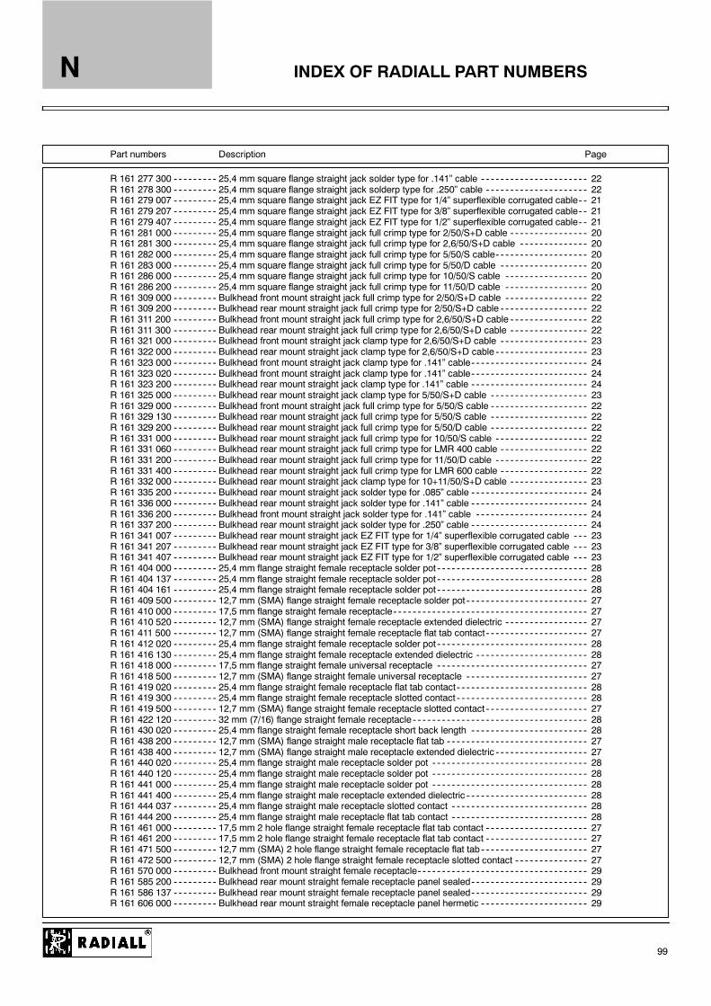
INDEX OF RADIALL PART NUMBERSN
99
Part numbers Description Page
R 161 277 300 25,4 mm square flange straight jack solder type for .141” cable 22R 161 278 300 25,4 mm square flange straight jack solderp type for .250” cable 22R 161 279 007 25,4 mm square flange straight jack EZ FIT type for 1/4” superflexible corrugated cable 21R 161 279 207 25,4 mm square flange straight jack EZ FIT type for 3/8” superflexible corrugated cable 21R 161 279 407 25,4 mm square flange straight jack EZ FIT type for 1/2” superflexible corrugated cable 21R 161 281 000 25,4 mm square flange straight jack full crimp type for 2/50/S+D cable 20R 161 281 300 25,4 mm square flange straight jack full crimp type for 2,6/50/S+D cable 20R 161 282 000 25,4 mm square flange straight jack full crimp type for 5/50/S cable 20R 161 283 000 25,4 mm square flange straight jack full crimp type for 5/50/D cable 20R 161 286 000 25,4 mm square flange straight jack full crimp type for 10/50/S cable 20R 161 286 200 25,4 mm square flange straight jack full crimp type for 11/50/D cable 20R 161 309 000 Bulkhead front mount straight jack full crimp type for 2/50/S+D cable 22R 161 309 200 Bulkhead rear mount straight jack full crimp type for 2/50/S+D cable 22R 161 311 200 Bulkhead front mount straight jack full crimp type for 2,6/50/S+D cable 22R 161 311 300 Bulkhead rear mount straight jack full crimp type for 2,6/50/S+D cable 22R 161 321 000 Bulkhead front mount straight jack clamp type for 2,6/50/S+D cable 23R 161 322 000 Bulkhead rear mount straight jack clamp type for 2,6/50/S+D cable 23R 161 323 000 Bulkhead front mount straight jack clamp type for .141” cable 24R 161 323 020 Bulkhead front mount straight jack clamp type for .141” cable 24R 161 323 200 Bulkhead rear mount straight jack clamp type for .141” cable 24R 161 325 000 Bulkhead rear mount straight jack clamp type for 5/50/S+D cable 23R 161 329 000 Bulkhead front mount straight jack full crimp type for 5/50/S cable 22R 161 329 130 Bulkhead rear mount straight jack full crimp type for 5/50/S cable 22R 161 329 200 Bulkhead rear mount straight jack full crimp type for 5/50/D cable 22R 161 331 000 Bulkhead rear mount straight jack full crimp type for 10/50/S cable 22R 161 331 060 Bulkhead rear mount straight jack full crimp type for LMR 400 cable 22R 161 331 200 Bulkhead rear mount straight jack full crimp type for 11/50/D cable 22R 161 331 400 Bulkhead rear mount straight jack full crimp type for LMR 600 cable 22R 161 332 000 Bulkhead rear mount straight jack clamp type for 10+11/50/S+D cable 23R 161 335 200 Bulkhead rear mount straight jack solder type for .085” cable 24R 161 336 000 Bulkhead rear mount straight jack solder type for .141” cable 24R 161 336 200 Bulkhead front mount straight jack solder type for .141” cable 24R 161 337 200 Bulkhead rear mount straight jack solder type for .250” cable 24R 161 341 007 Bulkhead rear mount straight jack EZ FIT type for 1/4” superflexible corrugated cable 23R 161 341 207 Bulkhead rear mount straight jack EZ FIT type for 3/8” superflexible corrugated cable 23R 161 341 407 Bulkhead rear mount straight jack EZ FIT type for 1/2” superflexible corrugated cable 23R 161 404 000 25,4 mm flange straight female receptacle solder pot 28R 161 404 137 25,4 mm flange straight female receptacle solder pot 28R 161 404 161 25,4 mm flange straight female receptacle solder pot 28R 161 409 500 12,7 mm (SMA) flange straight female receptacle solder pot 27R 161 410 000 17,5 mm flange straight female receptacle 27R 161 410 520 12,7 mm (SMA) flange straight female receptacle extended dielectric 27R 161 411 500 12,7 mm (SMA) flange straight female receptacle flat tab contact 27R 161 412 020 25,4 mm flange straight female receptacle solder pot 28R 161 416 130 25,4 mm flange straight female receptacle extended dielectric 28R 161 418 000 17,5 mm flange straight female universal receptacle 27R 161 418 500 12,7 mm (SMA) flange straight female universal receptacle 27R 161 419 020 25,4 mm flange straight female receptacle flat tab contact 28R 161 419 300 25,4 mm flange straight female receptacle slotted contact 28R 161 419 500 12,7 mm (SMA) flange straight female receptacle slotted contact 27R 161 422 120 32 mm (7/16) flange straight female receptacle 28R 161 430 020 25,4 mm flange straight female receptacle short back length 28R 161 438 200 12,7 mm (SMA) flange straight male receptacle flat tab 27R 161 438 400 12,7 mm (SMA) flange straight male receptacle extended dielectric 27R 161 440 020 25,4 mm flange straight male receptacle solder pot 28R 161 440 120 25,4 mm flange straight male receptacle solder pot 28R 161 441 000 25,4 mm flange straight male receptacle solder pot 28R 161 441 400 25,4 mm flange straight male receptacle extended dielectric 28R 161 444 037 25,4 mm flange straight male receptacle slotted contact 28R 161 444 200 25,4 mm flange straight male receptacle flat tab contact 28R 161 461 000 17,5 mm 2 hole flange straight female receptacle flat tab contact 27R 161 461 200 17,5 mm 2 hole flange straight female receptacle flat tab contact 27R 161 471 500 12,7 mm (SMA) 2 hole flange straight female receptacle flat tab 27R 161 472 500 12,7 mm (SMA) 2 hole flange straight female receptacle slotted contact 27R 161 570 000 Bulkhead front mount straight female receptacle 29R 161 585 200 Bulkhead rear mount straight female receptacle panel sealed 29R 161 586 137 Bulkhead rear mount straight female receptacle panel sealed 29R 161 606 000 Bulkhead rear mount straight female receptacle panel hermetic 29
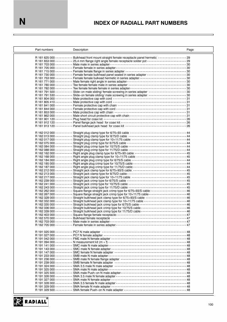
INDEX OF RADIALL PART NUMBERSN
100
Part numbers Description Page
R 161 625 000 Bulkhead front mount straight female receptacle panel hermetic 29R 161 653 000 25,4 mm flange right angle female receptacle solder pot 29R 161 703 000 Male male in series adapter 30R 161 705 000 Female female in series adapter 30R 161 715 000 Female female flange in series adapter 30R 161 730 000 Female female bulkhead panel sealed in series adapter 30R 161 753 000 Female female bulkead hermetic in series adapter 30R 161 771 000 Male female right angle in series adapter 30R 161 780 000 Tee female female male in series adapter 30R 161 782 000 Tee female female female in series adapter 30R 161 791 500 Slide--on male sliding/ female screwing in series adapter 30R 161 791 530 Slide--on female sliding/ male screwing in series adapter 30R 161 804 000 Male protective cap with cord 31R 161 805 410 Male protective cap with cord 31R 161 841 000 Female protective cap with chain 31R 161 844 000 Female protective cap with cord 31R 161 853 000 Male protective cap with chain 31R 161 862 000 Male short circuit protective cap with chain 31R 161 901 120 Plug head for coaxi kit 26R 161 912 120 Panel flange jack head for coaxi kit 26R 161 913 120 Panel bulkhead jack head for coaxi kit 26
R 162 012 000 Straight plug clamp type for 6/75+93 cable 44R 162 013 000 Straight plug clamp type for 8/75/D cable 44R 162 017 000 Straight plug clamp type for 10+11/75 cable 44R 162 075 000 Straight plug crimp type for 6/75/S cable 44R 162 084 000 Straight plug crimp type for 10/75/S cable 44R 162 088 000 Straight plug crimp type for 11/75/D cable 44R 162 162 000 Right angle plug clamp type for 6/75+93 cable 45R 162 168 000 Right angle plug clamp type for 10+11/75 cable 45R 162 184 000 Right angle plug crimp type for 6/75/S cable 44R 162 185 000 Right angle plug crimp type for 10/75/S cable 44R 162 187 000 Right angle plug crimp type for 11/75/D cable 44R 162 212 000 Straight jack clamp type for 6/75+93/S cable 45R 162 213 000 Straight jack clamp type for 8/75/D cable 45R 162 217 000 Straight jack clamp type for 10+11/75 cable 45R 162 239 000 Straight jack crimp type for 6/75/S cable 45R 162 241 000 Straight jack crimp type for 10/75/S cable 45R 162 243 000 Straight jack crimp type for 11/75/D cable 45R 162 262 000 Square flange straight jack crimp type for 6/75+93/S cable 46R 162 267 000 Square flange straight jack crimp type for 10+11/75 cable 46R 162 328 000 Straight bulkhead jack clamp type for 6/75+93/S cable 46R 162 332 000 Straight bulkhead jack clamp type for 10+11/75 cable 46R 162 335 000 Straight bulkhead jack crimp type for 6/75/S cable 46R 162 336 000 Straight bulkhead jack crimp type for 10/75/S cable 46R 162 339 000 Straight bulkhead jack crimp type for 11/75/D cable 46R 162 403 000 Square flange female receptacle 47R 162 570 000 Bulkhead female receptacle 47R 162 703 000 Male male in series adapter 47R 162 705 000 Female female in series adapter 47
R 191 025 000 PC7 N male adapter 48R 191 027 000 PC7 N female adapter 48R 191 042 000 FME male N female adapter 48R 191 094 000 N measurement kit (m + f) 48R 191 141 000 SMC male N male adapter 48R 191 143 000 SMC male N female adapter 48R 191 147 000 SMC female N female adapter 48R 191 233 000 SMB male N male adapter 48R 191 236 000 SMB male N female flange adapter 48R 191 239 000 SMB female N female adapter 48R 191 324 000 SMA 3.5 male N male adapter 48R 191 325 000 SMA male N male adapter 48R 191 325 500 SMA male Push--on N male adapter 48R 191 326 000 SMA 3.5 male N female adapter 48R 191 327 000 SMA male N female adapter 48R 191 328 000 SMA 3.5 female N male adapter 48R 191 329 000 SMA female N male adapter 48R 191 329 500 SMA female Push--on N male adapter 48

INDEX OF RADIALL PART NUMBERSN
101
Part numbers Description Page
R 191 330 000 SMA 3.5 female N female adapter 48R 191 331 000 SMA female N female adapter 48R 191 417 000 BNC male N male adapter 48R 191 417 500 BNC male Push--on N male adapter 48R 191 419 000 BNC male N female adapter 48R 191 421 000 BNC female N male adapter 48R 191 421 500 BNC female Push--on N male adapter 48R 191 422 000 BNC female N female bulkhead adapter 48R 191 511 000 TNC male N female adapter 48R 191 513 000 TNC female N male adapter 48R 191 514 000 TNC female N female flange adapter 48R 191 703 000 C female N male adapter 48R 191 705 000 C male N female adapter 48R 191 708 000 C female N female flange adapter 48R 191 720 000 7/16 female N male adapter 48R 191 721 000 7/16 male N male adapter 48R 191 722 000 7/16 male N female adapter 48R 191 723 000 7/16 female N female adapter 48R 191 731 000 UHF female N male adapter 48R 191 733 000 UHF male N female adapter 48R 191 737 000 HN male N female adapter 48R 191 741 000 LC female N female adapter 48R 191 745 000 LC male N female adapter 48
R 192 417 000 BNC 75 male N 75 male adapter 48R 192 418 000 BNC 75 female N 75 female adapter 48R 192 419 000 BNC 75 male N 75 female adapter 48R 192 421 000 BNC 75 female N 75 male adapter 48R 192 770 000 1.6/5.6 screw--on male N 75 female adapter 48R 192 771 000 1.6/5.6 screw--on snap--on female N 75 female adapter 48R 192 775 000 1.6/5.6 screw--on male N 75 male adapter 48R 192 777 000 1.6/5.6 screw--on snap--on female N 75 male adapter 48
R 280 008 030 Tips for coaxi kit clamp type for 5/50/S+D cable 26R 280 017 030 Tips for coaxi kit clamp type for 10+11/50/S+D cable 26R 280 021 200 Tips for coaxi kit EZ FIT type for 1/4” superflexible corrugated cable 26R 280 022 200 Tips for coaxi kit EZ FIT type for 1/2” superflexible corrugated cable 26R 280 023 200 Tips for coaxi kit EZ FIT type for 3/8” superflexible corrugated cable 26R 280 460 000 Field replaceable contact flat tab 32R 280 461 000 Field replaceable contact flat tab 32R 280 462 000 Field replaceable contact cylindrical tab 32R 280 463 000 Field replaceable contact cylindrical tab 32R 280 464 000 Field replaceable contact symetrical 32R 280 465 000 Field replaceable contact flat recessed tab 32R 280 467 000 Field replaceable isolators 32R 280 468 000 Field replaceable isolators 32R 280 637 020 Heatshrink sleeve 33R 280 637 030 Heatshrink sleeve 33R 280 637 040 Heatshrink sleeve 33R 280 637 050 Heatshrink sleeve 33R 280 651 030 Tips for coaxi kit crimp type for 5/50/S cable 26R 280 651 230 Tips for coaxi kit crimp type for 5/50/D cable 26R 280 663 030 Tips for coaxi kit crimp type for 10/50/S cable 26R 280 664 030 Tips for coaxi kit crimp type for 11/50/D cable 26R 280 940 000 Glass bead for sealing of universal receptacle 33
R 282 051 000 Stripping tool .085 54R 282 053 000 Stripping tool .141 55R 282 054 000 Stripping tool .250 56R 282 055 000 Replacement stripping blade 54R 282 056 085 Replacement coning blade 54R 282 056 118 Replacement coning blade 55R 282 056 250 Replacement coning blade 56R 282 063 000 Coning and length--setting tool 0.125 long on .085 54R 282 066 010 Coning and length--setting tool 0.177 long on .141 55R 282 074 020 Coning and length--setting tool 0.177 long on .250 56R 282 078 000 Universal stripping tool 51R 282 078 200 Red stripping cassette 51R 282 078 220 Yellow stripping cassette 51

INDEX OF RADIALL PART NUMBERSN
102
Part numbers Description Page
R 282 078 500 Ajustement bit 51R 282 102 000 Kit : bending of semi--rigid cables 57R 282 114 125 Kit : stripping and coning for .085” cable 54R 282 114 168 Kit : stripping and coning for .141” cable 55R 282 114 208 Kit : stripping and coning for .250” cable 56R 282 124 000 Kit : stripping and crimping for 5/50/S + D AND 6/75+93/S+D cable 50R 282 124 100 Kit : stripping and crimping for 10+11/50+75/S+D cable 51R 282 125 010 Kit for solder N series on semi--rigid cables 53R 282 201 000 Cutting collet 50R 282 202 000 Tightening tool 58R 282 211 000 Crimping tool 52R 282 223 000 Crimping tool 50--52R 282 231 000 Crimping tool 51--52R 282 235 003 Dies 52R 282 235 011 Dies 52R 282 235 013 Dies 52R 282 235 037 Dies 52R 282 235 116 Dies 52R 282 235 166 Dies 52R 282 271 000 Crimping tool 52R 282 303 020 Torque wrench 170 Ncm 58R 282 303 220 Torque wrench 950 Ncm 58R 282 344 127 .05” male hex key 54R 282 344 150 .059” male hex key 54R 282 730 160 .250” dielectric insertion tool + plunger for jacks 53R 282 730 161 .141” dielectric insertion tool + plunger for jacks 53R 282 740 030 Soldering fixture assembly 53R 282 744 260 Soldering fixture for female center contact 53R 282 744 261 Soldering fixture for male center contact 53R 282 744 300 Soldering fixture for .085” cable 53R 282 744 310 Soldering fixture for .141” cable 53R 282 744 320 Soldering fixture for .141” cable 53R 282 744 330 Soldering fixture for .250” cable 53R 282 744 340 Soldering fixture for N plug .141” cable 53R 282 744 350 Soldering fixture for N plug .250” cable 53R 282 750 000 Bending tool 57R 282 751 050 Bending gauge .085” 57R 282 751 051 Bending gauge .085” 57R 282 751 070 Bending gauge .141” 57R 282 751 071 Bending gauge .141” 57R 282 751 080 Bending gauge .250” 57R 282 790 010 Scalpel 51R 282 800 000 Joule effect soldering device 49R 282 803 000 Fume extraction device 49R 282 862 070 Solder gauge thickness .0138” 53R 282 862 080 Solder gauge thickness .0177” 53R 282 862 090 Solder gauge thickness .0276” 53R 282 864 110 Blade installation gauge .085” 54R 282 864 120 Blade installation gauge .141” 55R 282 864 140 Blade installation gauge .250” 56R 282 915 030 Dielectric recess cool for .141” 53R 282 915 040 Dielectric recess cool for .250” 53
R 285 720 063 N straight plug/ 3/8” cable / 7/16 straight plug /150 cm 41R 285 720 083 N straight plug/ 1/2” cable / 7/16 straight plug /150 cm 41R 285 724 042 N right angle plug/ 1/4” cable / 7/16 flange jack /100 cm 41R 285 725 063 N straight plug/ 3/8” cable / 7/16 flange jack /150 cm 41R 285 725 083 N straight plug/ 1/2” cable / 7/16 flange jack /150 cm 41R 285 780 063 2 N straight plugs / 3/8” cable / 150 cm 41R 285 780 083 2 N straight plugs / 1/2” cable / 150 cm 41R 285 783 063 N straight plug / 3/8” cable / N right angle plug /150 cm 41R 285 786 063 N right angle plug / 3/8” cable / N bulkhead jack /150 cm 41
R 299 510 000 Universal stripping tool for 5/50/S+ D and 6/75+93/S+D 50R 299 511 001 Brown stripping cassette 50R 299 511 011 Green stripping cassette 50R 299 511 012 Yellow stripping cassette 50