N Series Catalog 2016 (A4)
24
N SERIES High Density Mini-Modular Connectors
Transcript of N Series Catalog 2016 (A4)

N seriesHigh Density Mini-Modular Connectors

FeATUres BeNeFiTsloW InSERtIon/EXtRactIon foRcESThe angle of the socket wires allows tight control of the pin insertion and extraction forces. The spring wires are smoothly defl ected to make line contact with the pin.
HIGH DEnSItY IntERconnEct SYStEMSSignifi cant reductions in size and weight of sub-system designs. No additional hardware is required to overcome mating and un-mating forces.
lonG contact lIfEThe smooth and light wiping action minimizes wear on thecontact surfaces. Contacts perform up to 100,000 insertion/ extraction cycles with minimal degradation in performance.
loW coSt of oWnERSHIpThe Hypertac contact technology will surpass most product requirements, thus eliminating the burden and cost of having to replace the connector or the entire subsystem.
loWER contact RESIStancEThe design provides a far greater contact area and the wiping action of the wires insures a clean and polished contact surface. Our contact technology has half the resistance of conventional contact designs.
loW poWER conSUMptIonThe lower contact resistance of our technology results in a lower voltage drop across the connector reducing the power consumption and heat generation within the system.
HIGHER cURREnt RatInGSThe design parameters of the contact (e.g., the number, diameter and angle of the wires) may be modifi ed for any requirement. The number of wires can be increased so the contact area is distributed over a larger surface. Thus, the high current carried by each wire because of its intimate line contact, can be multiplied many times.
MaXIMUM contact pERfoRMancEThe lower contact resistance of the Hypertac contact reduces heat build-up; therefore Hypertac contacts are able to handle far greater current in smaller contact assemblies without the detrimental effects of high temperature.
IMMUnItY to SHocK & VIbRatIonThe low mass and resultant low inertia of the wires enable them to follow the most abrupt or extreme excursions of the pin without loss of contact. The contact area extends 360 degrees around the pin and is uniform over its entire length.The 3 dimensional symmetry of the Hypertac contact design guarantees electrical continuity in all circumstances.
RElIabIlItY UnDER HaRSH EnVIRonMEntSHarsh environmental conditions require connectors that will sustain their electrical integrity even under the most demanding conditions such as shock and vibration. The Hypertac contact provides unmatched stability in demanding environments when failure is not an option.
HYPerBOLOiDTeCHNOLOgY
Smiths Connectors offers an extensive range of superior contact technologies suitable for standard and custom solutions. Hypertac® (HYPERboloid conTACT) is the original superior performing hyperboloid contact technology designed for use in all applications and in harsh and demanding environments where high reliability and safety are critical. The inherent electrical and mechanical characteristics of the Hypertac hyperboloid contact ensures unrivalled performance in terms of reliability, number of mating cycles, low contact force and minimal contact resistance. The shape of the contact sleeve is formed by hyperbolically arranged contact wires, which align themselves elastically as contact lines around the pin, providing a number of linear contact paths.

3
n SERIES
tablE of contEntS
N series .............................................................................................................................4 Features & Benefits .................................................................................................................4 Frames:
Frame B ....................................................................................................................................5 Frame BV ..................................................................................................................................6 Frame BY ..................................................................................................................................7 Frame H ....................................................................................................................................8 Frame JV ..................................................................................................................................9 Frame JY ................................................................................................................................10 Modules:
Technical Characterisitics .....................................................................................................11 Module H ................................................................................................................................12 Module K .................................................................................................................................13 Module P .................................................................................................................................14 Module T .................................................................................................................................15 Module V .................................................................................................................................16 Module V Coax ......................................................................................................................17 Accessories .................................................................................................................18 Mounting Dimensions ...........................................................................................................19 How to Order ..........................................................................................................................20 Markets & Applications .........................................................................................................21 Smiths Connectors Product Lines .......................................................................................23

4
n SERIES
Smiths Connectors’ N Series high density, modular rack and panel connectors employ a do-it-yourself system based on the principle of building blocks. The N Series system is composed of two elements: modules and frames. Modules of various styles and contact types, including signal and coaxial, can be combined into custom arrangements within a single connector frame. This allows the user to build a connector that addresses and fulfills their exact requirements with off-the-shelf components.
Ideal for rugged and rack and panel applications, the N Series connectors utilize the unparalleled performance of Hypertac® hyperboloid contact technology to provide high cycle life, low insertion/extraction forces and immunity to shock and vibration. This ensures both smooth and easy mating and maximum performance in connectors with large quantities of contacts.
The contacts are mounted in small plastic blocks and are removable for easy assembly and repair. The frames which hold the modules in position range from basic, only consisting of two side rails and end caps, to more complex, including Jackscrews, hoods and cable clamps. To conform to almost any combination of modules, all frames are available in numerous lengths. With the N Series, specially designed connectors can be purchased quickly and inexpensively, eliminating the extra cost and delay of custom tooling.
N series CONNeCTOrs
FeATUres & BeNeFiTs ► low insertion / extraction forces ► High density interconnect systems
► Reliability in harsh environments ► Immunity to shock and vibration
► Long contact life
► Minimal contact resistance
► Efficient power consumption
► High current ratings
► low cost of ownership
► Design flexibility ► Allows up to 900 contact positions
► Building block system composed of custom module combinations within a connector frame
► Keying system available
► Removable signal and coax contact types available
► Jackscrews available in half-turn quick disconnect
► Float mountable for blind mating
► cable to chassis, cable to cable and rack and panel applications
APPLiCATiONs ► Rack and panel solutions
► Standard N Series
► Available keying system
► Available locking system
► Available float mounting
► cable solutions ► Hooded with rounded or flat cable security clamps
► Metal backshell with adjustable cable clamp
► Available jackscrew feature
► Full range of accessories offered
► Market applications ► Test equipment
► Burn-in stands
► Security systems
► Medical equipment
5
n SERIES
N series CONNeCTOrs
FrAmesDimensions & Specifications
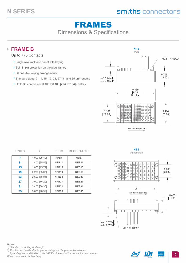
► fRaME b Up to 775 Contacts
► Single row, rack and panel with keying
► Built-in pin protection on the plug frames
► 36 possible keying arrangements
► Standard sizes: 7, 11, 15, 19, 23, 27, 31 and 35 unit lengths
► Up to 35 contacts on 0.100 x 0.100 [2.54 x 2.54] centers
nEbReceptacle
Notes:1) Standard mounting stud length.2) For thicker chassis, this longer mounting stud length can be selected
by adding the modification code “-479” to the end of the connector part number.Dimensions are in inches [mm].
npbPlug
Module Sequence
Module Sequence
UnItS X plUG REcEptaclE
7 1.000 [25.40] npb7 nEb7
11 1.400 [35.56] npb11 nEb11
15 1.800 [45.72] npb15 nEb15
19 2.200 [55.88] npb19 nEb19
23 2.600 [66.04] npb23 nEb23
27 3.000 [76.20] npb27 nEb27
31 3.400 [86.36] npb31 nEb31
35 3.800 [96.52] npb35 nEb35

6
n SERIES
Notes: 1) Standard mounting stud length.
2) For thicker chassis, this longer mounting stud length can be selected by adding the modification code “-479” to the end of the connector part number.
Dimensions are in inches [mm].
► fRaME bV Up to 720 Contacts
► Threaded Jackscrew extractor
► 36 possible keying arrangements
► Standard sizes: 11, 15, 19, 23, 27, 31 and 35 unit lengths
► Up to 320 contacts on 0.100 x 0.100 [2.54 x 2.54] centers
► Built-in pin protection on the plug frames
► Allow 3 units for Jackscrew
nEbVReceptacle
npbVPlug
Module Sequence
Module Sequence
UnItS X plUG REcEptaclE
7 1.000 [25.40] npbV7 nEbV7
11 1.400 [35.56] npbV11 nEbV11
15 1.800 [45.72] npbV15 nEbV15
19 2.200 [55.88] npbV19 nEbV19
23 2.600 [66.04] npbV23 nEbV23
27 3.000 [76.20] npbV27 nEbV27
31 3.400 [86.36] npbV31 nEbV31
35 3.800 [96.52] npbV35 nEbV35

7
n SERIES
► fRaME bY Up to 900 Contacts
► 180˚ quick turn jack provides greater than 15,000 mating cycles
► Great for test equipment, burn-in stands, security systems, and medical equipment
► Less than 1 second mating/unmating operation
► Crimp, solder cup, dip solder, and Wire Wrap® terminations
► Wiping action pin and sockets
► Provides 20 to 400 contacts in a single mating
► 4 or 9 ampere contacts mixed to your needs
► Built-in pin protection on the plug frames
► Standard frame sizes: 11, 15, 19, 23, 27, 31, 35 and 45 unit lengths
nEbY Receptacle
Notes:1) Standard mounting stud length.2) For thicker chassis, this longer mounting stud length can be selected by adding
the modification code “-479” to the end of the connector part number.Dimensions are in inches [mm].
npbYPlug
Module Sequence
Module Sequence
UnItS X plUG REcEptaclE
11 1.400 [35.56] npbY11 nEbY11
15 1.800 [45.72] npbY15 nEbY15
19 2.200 [55.88] npbY19 nEbY19
23 2.600 [66.04] npbY23 nEbY23
27 3.000 [76.20] npbY27 nEbY27
31 3.400 [86.36] npbY31 nEbY31
35 3.800 [96.52] npbY35 nEbY35
45 4.800 [121.92] npbY45 nEbY45

npHPlug
nEHReceptacle
8
n SERIES
► fRaME H Up to 775 Contacts
► Float mounting with heavy duty guides
► Max. radial play 0.049 [1.254] from centers
► Single row, rack and panel with keying
► Built-in pin protection on the plug frames
► 36 possible keying combinations
► Standard sizes: 7, 11, 15, 19, 23, 27, 31 and 35 unit lengths
► Up to 350 contacts on 0.100 x 0.100 [2.54 X 2.54] centers
®File No.: UL E102195
Module Sequence
Module Sequence
UnItS Y plUG REcEptaclE
7 2.000 [50.80] npH7 nEbV7
11 2.400 [60.96] npH11 nEH11
15 2.800 [71.12] npH15 nEH15
19 3.200 [81.28] npH19 nEH19
23 3.600 [91.44] npH23 nEH23
27 4.000 [101.60] npH27 nEH27
31 4.400 [111.76] npH31 nEH31
35 4.800 [121.92] npH35 nEH35
Dimensions are in inches [mm].

9
n SERIES
► fRaME JV plUG Up to 775 Contacts
► Hooded with cable clamp
► Threaded Jackscrew extractor
► Single row, rack and panel with keying
► Built-in pin protection on the plug frames
► 36 possible keying combinations
► Standard sizes: 11, 15, 19, 23, 27, 31 and 35 unit lengths
► Up to 350 contacts on 2.54 x 2.54 centers
► Jackscrew uses 3 units
► Adjustable cable clamp will hold 80 to 320 conductors of 22 to 28 AWG; adjusts 0.500 [12.70] to 1.00 [25.40] min.
► Refer to NEBV or NEPJV frame for mating receptacle
► Up to 320 contacts on 0.100 x 0.100 [2.54 x 2.54] centers
npJVPlug
Notes: 1) Frame JV mates with NEBV or NEPJV.2) Protective dust cover part number: YHD0369-XX (XX = number of units).Dimensions are in inches [mm].
Module Sequence
UnItS Y Z plUG REcEptaclE
11 1.993 [50.64] 0.884 [22.47] npJV11 nEJV11
15 2.393 [60.80] 1.084 [27.55] npJV15 nEJV15
19 2.794 [70.96] 1.284 [32.63] npJV19 nEJV19
23 3.194 [81.12] 1.484 [37.71] npJV23 nEJV23
27 3.594 [91.28] 1.684 [42.79] npJV27 nEJV27
31 4.000 [101.44] 1.884 [47.87] npJV31 nEJV31
35 4.393 [111.60] 2.084 [52.95] npJV35 nEJV35

10
n SERIES
► fRaME JY Up to 900 Contacts
► 180˚ quick turn jack provides greater than 15,000 mating cycles
► Great for test equipment, burn-in stands, security systems, and medical equipment
► Less than 1 second mating/unmating operation
► Crimp, solder cup, dip solder, and Wire Wrap® terminations
► Wiping action pin and sockets
► Provides 20 to 400 contacts in a single mating
► 4 or 9 ampere contacts mixed to your needs
► Built-in pin protection on the plug frames
► Standard frame sizes: 11, 15, 19, 23, 27, 31, 35 and 45 unit lengths
► Refer to NEBY or NEPJY frame for mating receptacle
► Adjustable Cable Clamp: 0.500 [12.70] to 1.00 [25.40]
Notes: 1) Frame JY mates with NEBY or NEPJY.
2) Protective dust cover for plug only part number: ZMP0025-XX (XX = number of modules).Dimensions are in inches [mm].
UnItS Y Z plUG REcEptaclE
11 1.993 [50.64] 0.884 [22.47] npJY11 nEJY11
15 2.393 [60.80] 1.084 [27.55] npJY15 nEJY15
19 2.794 [70.96] 1.284 [32.63] npJY19 nEJY19
23 3.194 [81.12] 1.484 [37.71] npJY23 nEJY23
27 3.594 [91.28] 1.684 [42.79] npJY27 nEJY27
31 4.000 [101.44] 1.884 [47.87] npJY31 nEJY31
35 4.393 [111.60] 2.084 [52.95] npJY35 nEJY35
45 5.400 [137.16] 2.500 [63.50] npJY45 nEJY45
npJYPlug
Module Sequence

11
n SERIES
mODULesSpecifications & Ordering Information
H K p t V V coaX
current Rating 1 A 4 A 4 A 9 A 25 A(1) —
contact Resistance (mΩ) < 8.0 < 5.0 < 5.0 < 2.5 < 1.5 < 8.0 / < 2.0(2)
nominal Impedance — 50 Ω
frequency Range — DC 3 GHz to DC 18 GHz(3)
Extraction force (oz.)(per contact) 0.3 to 1.6* 0.5 to 2.0 0.5 to 2.0 0.7 to 5.0 3.0 to 17.0 1.5 to 6.0
(3.0 average)
life cycle > 100,000 (contact) > 25,000 (connector)
breakdown Voltage (V RMS) > 750 > 1,400 > 1,400 > 2,000 > 1,600 —
DWV (V RMS) > 500 > 1,050 > 1,050 > 1,500 1,200 500
VSWR —< 1:20:1 (DC to 3 GHz) < 1:50:1 (3 to 18 GHz)
Rf transmission loss — 0.50 dB at 18 GHz
Insulation Resistance (MΩ at 500 VDC) 103 105 103 105 104 > 5,000
temperature Rating (°C) -55 to 125 -55 to 105 -55 to 105 -55 to 105 -55 to 105 -55 to 125
MatERIalS
pin Phosphor bronze Brass
Socket Beryllium copper wires and brass body
Insulator Nylon, 25% glass Glass filled nylon Glass filled nylon Glass filled nylon Nylon PTFE flourocarbon
contact platInG
pin 10/50 µin gold over nickel 50 µin gold over nickel
Socket Mating Surface 50 µin gold over nickel
Socket termination Gold flash over nickel
Socket body (optional) — Nickel over copper flash — — —
► tEcHnIcal cHaRactERIStIcS
Notes: 1) 25 A (free air), 17 A (bundled)2) Inner contact: < 8 mΩ; outer contact: < 2 mΩ3) DC 3 GHz: RH316; DC 18 GHz: GH405 Dimensions are in inches [mm].
12
n SERIES
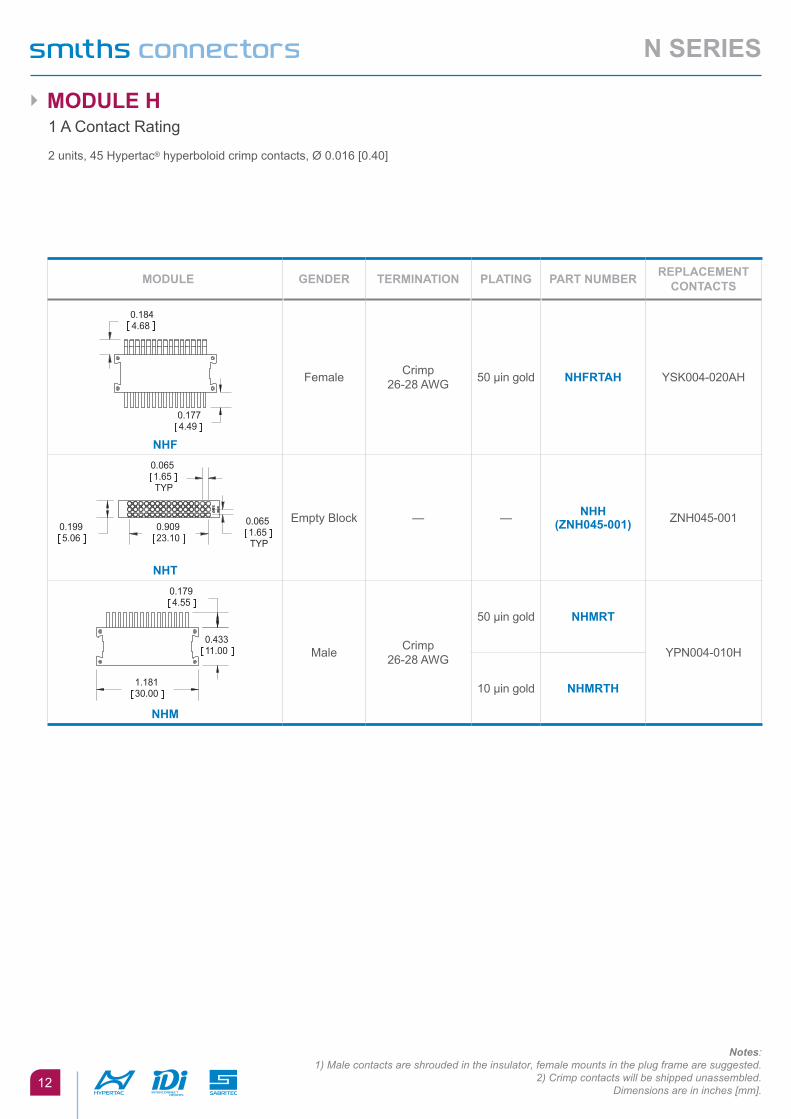
► MoDUlE H1 A Contact Rating
2 units, 45 Hypertac® hyperboloid crimp contacts, Ø 0.016 [0.40]
Notes:1) Male contacts are shrouded in the insulator, female mounts in the plug frame are suggested.
2) Crimp contacts will be shipped unassembled. Dimensions are in inches [mm].
MoDUlE GEnDER tERMInatIon platInG paRt nUMbER REplacEMEnt contactS
nHf
Female Crimp 26-28 AWG 50 µin gold nHfRtaH YSK004-020AH
nHt
Empty Block — — nHH (ZnH045-001) ZNH045-001
nHM
Male Crimp 26-28 AWG
50 µin gold nHMRt
YPN004-010H
10 µin gold nHMRtH

13
n SERIES
Notes: 1) Contacts will be shipped unassembled.Dimensions are in inches [mm].
MoDUlE GEnDER tERMInatIon platInG paRt nUMbER
REplacEMEnt contactS HolE I.D.
nKf
Female
Double Crimp22-24 AWG
50 µin gold nKfH2taH
YSK006-009AH
0.035 [0.90]
0.071 [1.80]
50 µin gold, nickel over copper flash on
socket bodynKfH2anH
Crimp22-26 AWG
50 µin gold nKfRtaH
YSK006-011ANH
0.035 [0.90]
0.051 [1.30]
50 µin gold, nickel over copper flash on
socket bodynKfRanH
Crimp18-20 AWG
50 µin gold nKfRRtaH
YSK006-089AH
0.055 [1.39]
0.071 [1.80]
50 µin gold, nickel over copper flash on
socket bodynKfRRanH
Solder Cup22 AWG
50 µin gold nKfStaH
YSK006-010ANH
0.039 [1.00]
0.055 [1.40]
50 µin gold, nickel over copper flash on
socket bodynKfSanH
nKHt
Empty Block — — nKHt
(ZnK010-001) — — —
nKM
Male
Double Crimp22-24 AWG
10 µin gold nKMH2t
YPN006-019G or H
0.035 [0.90]
0.071 [1.80]
50 µin gold nKMH2tH
Crimp22-26 AWG
10 µin gold nKMRt
YPN006-021G or H
0.035 [0.90]
0.051 [1.30]
50 µin gold nKMRtH
Crimp18-20 AWG
10 µin gold nKMRRt
YPN006-158G or H
0.055 [1.39]
0.071 [1.80]
50 µin gold nKMRRtH
Solder Cup22 AWG
10 µin gold nKMSt
YPN006-020G or H
0.039 [1.00]
0.055 [1.40]
50 µin gold nKMStH
► MoDUlE K 4 A Contact Rating
1 unit, 10 Hypertac® hyperboloid removable signal contacts, Ø 0.024 [0.60]
®File No.: UL E102195
14
n SERIES
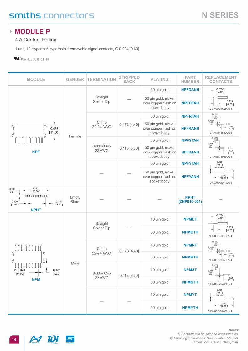
Notes:1) Contacts will be shipped unassembled.
2) Crimping instructions: Doc. number 550063.Dimensions are in inches [mm].
MoDUlE GEnDER tERMInatIon StRIppED bacK platInG paRt
nUMbERREplacEMEnt
contactS
npf
Female
Straight Solder Dip —
50 µin gold npfDanH
YSK006-032ANH
50 µin gold, nickel over copper flash on
socket bodynpfDtaH
Crimp22-24 AWG 0.173 [4.40]
50 µin gold npfRtaH
YSK006-015ANH
50 µin gold, nickel over copper flash on
socket bodynpfRanH
Solder Cup22 AWG 0.118 [3.30]
50 µin gold npfStaH
YSK006-016ANH
50 µin gold, nickel over copper flash on
socket bodynpfSanH
— —
50 µin gold npfYtaH
YSK006-031ANH
50 µin gold, nickel over copper flash on
socket bodynpfYanH
npHt
Empty Block — — — npHt
(Znp010-001) —
npM
Male
Straight Solder Dip —
10 µin gold npMDt
YPN006-047G or H50 µin gold npMDtH
Crimp22-24 AWG 0.173 [4.40]
10 µin gold npMRt
YPN006-025G or H50 µin gold npMRtH
Solder Cup22 AWG 0.118 [3.30]
10 µin gold npMSt
YPN006-026G or H50 µin gold npMStH
— —
10 µin gold npMYt
YPN006-046G or H 50 µin gold npMYtH
► MoDUlE p 4 A Contact Rating
1 unit, 10 Hypertac® hyperboloid removable signal contacts, Ø 0.024 [0.60]
®File No.: UL E102195

15
n SERIES
Notes: 1) Crimp contacts will be shipped unassembled.2) Wire Wrap is a trademark of Gardner Denver.Dimensions are in inches [mm].
MoDUlE GEnDER tERMInatIon StRIppED bacK platInG paRt
nUMbERREplacEMEnt
contactS
ntf
Female
Crimp 14, 16, 10 & 20 AWG
0.285 [7.20] 50 µin gold ntfRtaH
YSK015-025AH
Solder CupUp to 13 AWG — 50 µin gold ntfStaH
YSK015-026AH
— — 50 µin gold ntfVtaH
YSK015-027AH
ntHt
Empty Block — — —
ntHt (Znt005-
001)—
ntM
Male
Crimp 14, 16, 10 & 20 AWG
0.285 [7.20]
10 µin gold ntMRt
YPN015-016G or H50 µin gold ntMRtH
Solder CupUp to 13 AWG —
10 µin gold ntMSt
YPN015-017G or H50 µin gold ntMStH
— —
10 µin gold ntMVt
YPN015-018G or H50 µin gold ntMVtH
► MoDUlE t 9 A Contact Rating
2 units, 5 Hypertac® hyperboloid removable signal contacts, Ø 0.059 [1.50]
®File No.: UL E102195

16
n SERIES
MoDUlE GEnDER tERMInatIon paRt nUMbER REplacEMEnt contactS
nVf
FemaleCrimp
25 Amps (Free Air)17 Amps (Bundled)
12-18 AWGnVfp1taH* YSK025-031AH
nVf
FemaleEmpty Block — nVfH —
nVM
MaleEmpty Block — nVMH —
nVM
Male
Crimp25 Amps (Free Air)17 Amps (Bundled)
12-18 AWGnVMp1tH* YPN025-024H
► MoDUlE V25 A Power
2.5 units, 4 Hypertac® hyperboloid contactsCan be mounted by itself or in a frame
®File No.: UL E102195
Notes:Contacts shipped unassembled.Dimensions are in inches [mm].

17
n SERIES
► MoDUlE VCoax
2.5 units, 4 Hypertac® hyperboloid contacts (on both signal and ground)
®File No.: UL E102195
Notes:1) Please request specs from our customer service department. Dimensions are in inches [mm].
cablInG cRIMp (R) and (R1) SolDER (S)
cable RG316 & RG316DB RG405 & T-Flex 405
Socket 1.6 oz. at 4 units2.5 oz. at 20 units
S50301 & S50307
pin S50304 S50303 & S50308
MoDUlE GEnDER tERMInatIon paRt nUMbER REplacEMEnt contactS
nVf
Female
Crimp Coaxial for RG316 nVfRtaH YCX0315-002AH
Crimp Coaxial for RG316DB nVfR1taH YCX0315-019AH
nVf
Female Solder Coaxial for RG405 or T-Flex 405
nVfStaH YCX0315-001AH
nVM
Male
Crimp Coaxial for RG316 nVMRtH YCX0315-004H
Crimp Coaxial for RG316DB nVMR1tH YCX0315-018H
nVM
MaleSolder Coaxial for RG405 or T-Flex 405
nVMStH YCX0315-003H
nVf
Female Straight Dip Coax nVfDtaH Fixed Contacts cannot be removed

► MoDUlE accESSoRIES
18
n SERIES
MoDUlE H crimp tool crimp Die Set crimp positioner Insertion tool Extraction tool
femaleMale
AFM8 or M22520/2-01 —T1974T1973
T1970 —
MoDUlE K
Style RStyle RRJacket of H2
AFM8 —K547
K547-2K640
— S/DEM1.0060
MoDUlE p
all Styles AFM8 — K623-1 — S/DEM1.0060
MoDUlE t
all Styles AF8 — TP687 — S/DEM5.0150
MoDUlE V
all Styles M309 — T1981 — T1982
MoDUlE V coaX
center conductorouter conductor
AFM8HX3
—T1958 for RG316 orT2019 for RG316DB
T1957— — T1982

19
n SERIES
Notes:1) 59.0 oz. in. torque for mounting.2) Refer to individual frame type for standard length.Dimensions are in inches [mm].
mOUNTiNg DimeNsiONs
► SInGlE RoW fRaME MoUntInGFor Frame Type B, BV, BY, JV & JY
► float MoUntInGFor Frame Type H
plUG
REcEptaclE
UnItS X
7 1.000 [25.40]
11 1.400 [35.65]
15 1.800 [45.72]
19 2.200 [55.88]
23 2.600 [66.04]
27 3.000 [76.20]
31 3.400 [86.36]
35 3.800 [96.52]
45 4.800 [121.90]
UnItS Y
7 2.000 [50.80]
11 2.400 [60.96]
15 2.800 [71.12]
19 3.200 [81.28]
23 3.600 [91.44]
27 4.000 [101.60]
31 4.400 [111.76]
35 4.800 [121.92]
45 5.800 (147.32)

20
n SERIES
Vb
Notes:1) When part number exceeds 24 characters, please consult factory for special (abbreviated) part number.
2) The plug frame has a built in pin shroud (sockets may be used in plug frames, but not recommended).3) Consult factory when ordering straight dip solder tails with center jacking version.
Special cut out and modification - 872 is required.Dimensions are in inches [mm].
N series [Fixed]
1 2
12 iNsULATOr
p plUG E REcEptaclE
FrAme TYPe3b fRaME b
FrAme LeNgTH44 to
3 4 5
mODULe QUANTiTY + PArT NUmBer54 +
6 PLATiNg
H 50 µin GolD oVER nIcKEl
a 50 µin GolD oVER nIcKEl
t
t
5 6
fRaME bV Y fRaME bY
H fRaME H V fRaME JV Y fRaME JY
b
J J
0 UnItS(2) 2
Ma tAmount of same modules together within frame. (Drop “N” from beginning of module part number, see pg. 12 for all module part numbers). Example: 4AMST = 4 of the (L)AMST style modules. Separate each series of modules by “/”. Modules will be positioned in frame according to sequence listed.
S
t 10 µin GolD oVER nIcKEl
H
/ 2 + Hc t /
n / / /
Frame length is computed by multiplying the module units by module quantity and totaling the results. Apply 2 additional units for frames with Jackscrews.
HoW to oRDER

Industrial Rail oil & Gas
► Heavy equipment/machinery
► Servo drivers and encoders
► Robotics
► Factory automation
► Power supplies
► High spped trains
► Main lines
► Inter-cities/metros
► Signaling equipment
► Infrastructures
► Well-head logging recorders
► Smart PIGs
► Down hole monitoring systems
► Offshore exploration
► Seismic instrumentation
alternative Energy Medical Hybrid / Electric Vehicle
► Wind turbines
► Solar panels
► Power systems
► Energy storage systems
► MRI and CT scanning equipment
► Patient monitors
► Portable applications
► Catheters
► Therapeutic devices
► Electric motors
► Inverters
► Batteries
► Generators
► Power storage
mArKeTs & APPLiCATiONs
21
n SERIES

Disclaimer 2016
All of the information included in this catalog is believed to be accurate at the time of printing. It is recommended, however, that users should independently evaluate the suitability of each product for their intended application and be sure that each product is properly installed, used and maintained to achieve desired results.Smiths Connectors makes no warranties as to the accuracy or completeness of the information, and disclaims any liability regarding its use.Smiths Connectors reserves the right to modify design and specifications, in order to improve quality, keep pace with technological development or meet specific production requirements.
No reproduction or use without express permission of editorial and pictorial content, in any manner.

smiTHs CONNeCTOrs PrODUCT LiNes
circular EMI / EMp filter Heavy Duty
► Metal and plastic
► Industrial M12, M23, M40, M58
► Crimp and solder terminations
► Push/pull latch mechanism
► Colour coding
► EMI/RFI filtering and transient protection
► RoHS compliant solderless filter connectors available
► Filtered adapter for “bolt on” EMI/EMP solutions
► Filter hybrid capability
► Circular, ARINC, D-Subminiature, Micro-D
► Modular solution: signal, power, data contacts and fibre optics
► EMC shielding
► High pressure up to 35K PSI, 250°C
► High temperature up to 440°C
High power High Speed copper / fibre Mil / aero Standards
► Single and multi-way
► Circular and configurable rectangular
► Power contact up to 1,200 Amps
► Excellent performance in harsh environments
► Quadrax and Twinax connectors
► Fibre Optic Butt Joint, Expanded Beam and Floating Fibre Termini available
► ARINC and MIL-STD contacts
► Standard military interface
► ARINC 801
► ARINC interface
► Custom inserts
Modular / Rectangular pcb Spring probe
► Configurable modules for signal, power, coax, fibre optic and/or pneumatics
► Guided hardware for blind mating
► Easy configuration in a single frame
► For rack & panel and cable applications
► Low, medium and high density board-to-board, cable to board and stacking
► Signal, power, coax and high speed configurations
► Numerous termination styles
► Z-axis compliant
► Blind mate engagement
► High density
► Extreme miniaturization
► High reliability, multi-cycle performance

SMITHS CONNECTORSGLOBAL SUPPORT
AMERICAS EUROPE [email protected]
Costa Mesa, CA 1.714.371.1100
Hudson, MA 1.978.568.0451
Kansas City, KS 1.913.342.5544
France [email protected]
Germany [email protected]
Italy [email protected]
United Kingdom [email protected]
Shanghai, China 86.21.3318.4650
Suzhou, China 86.512.6273.1188
Singapore 65.6846.1655
visit us at | smithsconnectors.com |
Copyright© 2016 Smiths Connectors | All rights reserved | Version 1.1
Copyright© 2016 Smiths Connectors | All rights reserved | Version 1.3