n CAN to latent faultscan-newsletter.org/uploads/media/raw/b9a7c179f8e0... · The ISO 26262...
4
T he ISO 26262 standard for functional safety has replaced the IEC 61508 ge- neric standard in the devel- opment process of automo- tive embedded systems. ISO 26262 has brought the concept of latent multiple- point faults in addition to the commonly considered sin- gle-point faults. Therefore, it is worthwhile to assess the robustness of previous- ly specified automotive E/E (Electric/Electronic) sys- tems against latent faults. Nowadays automotive manufacturers are facing the big challenge of inte- grating a growing amount of software and electron- ics commonly delivered by numerous suppliers. This increasing complexity of automotive embedded sys- tems and related networks calls for a more rigorous approach to system devel- opment. With regards to minimizing the risk of phys- ical injury or environmental damage, stringent function- al safety requirements must be stipulated and consid- ered in conjunction with The susceptibility of CAN to latent faults A qualitative evaluation of the susceptibility of CAN communication to latent faults can extend the scope of functional safety assessment of in-vehicle embedded systems. other specific automotive re- quirements (e.g. high quality, target cost and delay objec- tives). The increasing im- portance of safety systems in modern cars strengthens the need for more robust and dependable electron- ic and software compo- nents. Risks resulting from hardware, random failures, or software systematic er- rors must be reduced so far as reasonably practicable throughout the foreseeable lifetime of the products. The automotive in- dustry now applies the ISO 26262 standard as best practice for functional safe- ty. According to ISO 26262, car manufacturers and sup- pliers are expected to agree on producing safety cases for automotive embedded systems. Every safety case must provide a clear, com- prehensible and defensi- ble argument, supported by qualitative and quantitative evidence that a system is ac- ceptably safe to operate in a particular environment. Typ- ically based on engineering judgment rather than on for- mal logic approach, the ar- gument of a safety goal must show that steps have been appropriately taken to deal with the hazards caused by malfunctioning behavior of a system. ISO 26262 defines a process framework and a procedure model along with necessary activities and methods to be considered throughout the life-cycle of safety critical systems in road vehicles. A key concept of ISO 26262 relies on the speci- fication of the “Automotive Safety Integrity Level (ASIL)” as one out of four discrete levels, each reflecting a set of necessary requirements, recommended diagnostic techniques and architectur- al constraints for avoiding an unreasonable residual risk. ASIL-D represents the most stringent level and ASIL-A indicates the least stringent level. After risk assessment and hazard analysis of oper- ational situations, an ASIL is assigned to each safety goal. Hence the required ASIL- specific values of the single- point fault metric and latent fault metric must be met for the functional path allocat- ed to a given safety goal. Data transmission of safety- critical data over CAN does belong to various functional paths targeting ASIL-C or -D in modern cars. Prior to the specifica- tion of ISO 26262, the func- tional safety analysis of a CAN network was based on the consideration of sin- gle-point faults [4, 5, 6, 7]. To cope with ISO 26262, it is highly desirable to ex- tend the related works by addressing the effects and the detection capability of la- tent faults in automotive net- working systems. ISO 26262 defines a latent fault as a multiple point fault whose presence is not detect- ed by a safety mechanism nor perceived by the driv- er within the multiple point fault detection interval. Af- ter a time span representing this interval, an undetected latent fault may allow another fault to cause a hazard. This work aims at qualitatively as- sessing the susceptibility of CAN communication to la- tent faults. Figure 1: Classification of failure modes [2] Author Lukusa Didier Kabulepa Institute for Embedded Systems Mannheim University of Applied Sciences John-Deere-Straße 85 DE-68163 Mannheim Tel.: 0621-292-6854 Fax: 0621-292-6-6854-2 Links www.hs-mannheim.de References Additional information ◆ B. Gaujal, N. Navet, “Fault Confinement Mechanisms on CAN: Analysis and Improvements”, IEEE Transactions On Vehicular Technology, 2001. ◆ N.Navet, Y.-Q. Song, “Performance and Fault Tolerance of Real-Time Applications Distributed over CAN (Controller Area Network)”, Submission for the CiA Awards 1997. ◆ E. Tran, “Multi-Bit Error Vulnerabilities in the Controller Area Network Protocol”, Carnegie Mellon University, Pittsburgh PA, USA, 1999. 36 CAN Newsletter 2/2014 System design
Transcript of n CAN to latent faultscan-newsletter.org/uploads/media/raw/b9a7c179f8e0... · The ISO 26262...
The ISO 26262 standard for functional safety has
replaced the IEC 61508 ge-neric standard in the devel-opment process of automo-tive embedded systems. ISO 26262 has brought the concept of latent multiple-point faults in addition to the commonly considered sin-gle-point faults. Therefore, it is worthwhile to assess the robustness of previous-ly specified automotive E/E (Electric/Electronic) sys-tems against latent faults.
Nowadays automotive manufacturers are facing the big challenge of inte-grating a growing amount of software and electron-ics commonly delivered by numerous suppliers. This increasing complexity of automotive embedded sys-tems and related networks calls for a more rigorous approach to system devel-opment. With regards to minimizing the risk of phys-ical injury or environmental damage, stringent function-al safety requirements must be stipulated and consid-ered in conjunction with
The susceptibility of CAN to latent faultsA qualitative evaluation of the susceptibility of CAN communication to latent faults can extend the scope of functional safety assessment of in-vehicle embedded systems.
other specific automotive re-quirements (e.g. high quality, target cost and delay objec-tives). The increasing im-portance of safety systems in modern cars strengthens the need for more robust and dependable electron-ic and software compo-nents. Risks resulting from hardware, random failures, or software systematic er-rors must be reduced so far as reasonably practicable throughout the foreseeable lifetime of the products.
The automotive in-dustry now applies the ISO 26262 standard as best practice for functional safe-ty. According to ISO 26262, car manufacturers and sup-pliers are expected to agree on producing safety cases for automotive embedded systems. Every safety case must provide a clear, com-prehensible and defensi-ble argument, supported by qualitative and quantitative evidence that a system is ac-ceptably safe to operate in a particular environment. Typ-ically based on engineering judgment rather than on for-mal logic approach, the ar-gument of a safety goal must show that steps have been appropriately taken to deal with the hazards caused by malfunctioning behavior of a system. ISO 26262 defines a process framework and a procedure model along with necessary activities and methods to be considered throughout the life-cycle of safety critical systems in road vehicles.
A key concept of ISO 26262 relies on the speci-fication of the “Automotive Safety Integrity Level (ASIL)”
as one out of four discrete levels, each reflecting a set of necessary requirements, recommended diagnostic techniques and architectur-al constraints for avoiding an unreasonable residual risk. ASIL-D represents the most stringent level and ASIL-A indicates the least stringent level. After risk assessment and hazard analysis of oper-ational situations, an ASIL is assigned to each safety goal. Hence the required ASIL-specific values of the single-point fault metric and latent fault metric must be met for the functional path allocat-ed to a given safety goal. Data transmission of safety-critical data over CAN does belong to various functional paths targeting ASIL-C or -D in modern cars.
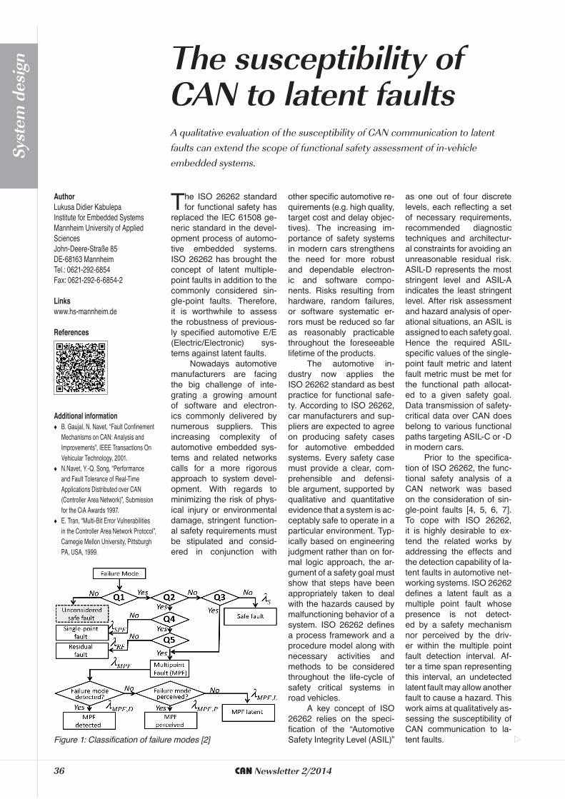
Prior to the specifica-tion of ISO 26262, the func-tional safety analysis of a CAN network was based on the consideration of sin-gle-point faults [4, 5, 6, 7]. To cope with ISO 26262, it is highly desirable to ex-tend the related works by addressing the effects and the detection capability of la-tent faults in automotive net-working systems. ISO 26262 defines a latent fault as a multiple point fault whose presence is not detect-ed by a safety mechanism nor perceived by the driv-er within the multiple point fault detection interval. Af-ter a time span representing this interval, an undetected latent fault may allow another fault to cause a hazard. This work aims at qualitatively as-sessing the susceptibility of CAN communication to la-tent faults. Figure 1: Classification of failure modes [2]
AuthorLukusa Didier KabulepaInstitute for Embedded Systems Mannheim University of Applied Sciences John-Deere-Straße 85DE-68163 Mannheim Tel.: 0621-292-6854 Fax: 0621-292-6-6854-2
Linkswww.hs-mannheim.de
References
Additional information ◆ B. Gaujal, N. Navet, “Fault Confinement
Mechanisms on CAN: Analysis and Improvements”, IEEE Transactions On Vehicular Technology, 2001.
◆ N.Navet, Y.-Q. Song, “Performance and Fault Tolerance of Real-Time Applications Distributed over CAN (Controller Area Network)”, Submission for the CiA Awards 1997.
◆ E. Tran, “Multi-Bit Error Vulnerabilities in the Controller Area Network Protocol”, Carnegie Mellon University, Pittsburgh PA, USA, 1999.
36 CAN Newsletter 2/2014
Syst
em d
esig
n
CAN built-in safety measures
Distributed automotive em-bedded systems mainly use a CAN network to transfer messages to various ECUs (Electronic Control Units). As a CAN network is also intend-ed to support data exchange amongst safety-critical func-tions, robust safety mea-sures are anchored in the re-lated protocol. In light of the transmission errors listed in IEC 61508 and ISO 26262, the intrinsic CAN safety mea-sures achieve a high error detection coverage. In some cases, this coverage of hard-ware safety mechanisms can be improved by means of software-based error detec-tion methods.
The CAN protocol im-plements five error detection mechanisms acting either at message level or at bit level:
◆ Cyclic redundancy check (CRC)
◆ Frame form check ◆ Acknowledge check ◆ Bit-monitoring ◆ Bit-stuffing
Cyclic redundancy check (CRC): A 15-bit CRC sequence is computed by the transmitting node for each message and verified upon reception. The select-ed hardware CRC polyno-mial guarantees a minimum Hamming distance of 6 in the unstuffed bit sequence of a CAN frame. The application of the CRC code represents a sufficient measure against data corruption. Thus the CAN hardware CRC is not a sufficient safety measure against masquerade errors. An additional CRC imple-mentation in software may help overcome this limitation of the basic CAN CRC if, for instance, the software CRC computation is not limited to the transmitted frame, but also applies to unsent data (e.g. a special key) a-priori
known by the transmitter and the intended receiver.
Frame form check: Predefined bit positions (i.e. CRC delimiter, ACK delimiter, EOF bit) within a CAN frame must always be transmitted as recessive bits. If a receiv-er detects a dominant bit in one of these positions a form error will be flagged. Addi-tionally the RTR and IDE bits must always exhibit a pre-defined value consistent with the actual format of the frame transmitted over the serial bus. The frame form check detects some data corruption errors, partial message dele-tion, and timing errors such as excessive jitters.
This error detection mechanism detects also er-roneous signal activities on
the CAN network if they are not compliant with specified CAN frame forms.
A c k n o w l e d g m e n t check: Every CAN transmit node expects an acknowl-edgement at the ACK bit po-sition. An acknowledgement error is flagged if a transmit-ter does not sample a domi-nant bit during the ACK slot. As a feedback signal, the acknowledge bit allows the transmitter to detect a partial message deletion or inser-tion occurred after the SOF bit. Moreover, some types of data corruption, delays and excessive jitters can be de-tected by means of the ac-knowledgment check.
Bit-monitoring: Every sending node monitors the transmitted bit level on the bus. A bit error is flagged if the monitored bit level is dif-ferent from the transmitted bit level. Bit-monitoring facil-itates the rapid detection of data bit corruption and tim-ing errors.
Bit-stuffing: The bit-stuffing method states that a bit of opposite polarity must be inserted after every five consecutive bits of the same
Safety levels ASIL D ASIL C ASIL BSafety
requirements LFM > 90 % LFM > 80 % LFM > 60 %
Table 1: LFM (latent fault metric) related requirements
C M Y CM MY CY CMY K
polarity. A stuff error is indi-cated if six consecutive bits of the same polarity are de-tected between the start of frame (SOF) and the CRC delimiter. The bit-stuffing method detects some types of data bit corruption on CAN networks.
These error detec-tion mechanisms are ac-companied by an efficient error signaling scheme in CAN networks. Each node starts sending an error frame to other nodes upon error detection. Since the error message does not obey the bit-stuffing rule, it can be notified by any node that should have missed to identify a previous error condition. Therefore a CAN network error remains un-detected only if it escapes the error detection mech-anisms of all active nodes within the network. The scope of error detection is not limited to the transmitter and the intended receiver.
In safety-critical appli-cations, the built-in safety measures of the CAN pro-tocol are typically expect-ed to be complemented by software-based error detec-tion methods in the safety layer in order to achieve a better qualitative coverage of the transmission errors mentioned in IEC 61508 and ISO 26262. An evalua-tion of software-based safe-ty mechanisms is beyond the scope of this work since they are commonly based on proprietary implementa-tions of software measures such as alive counter, time stamp, or software-CRC. In contrast to hardware com-ponents, software imple-mentations are only prone to systematic errors.
Assessment of latent faultsA latent fault is defined in ISO 26262-1 as a multi-ple-point fault whose pres-ence is not detected by a safety mechanism nor per-ceived before the under-lying combination of faults can lead to a violation of a
safety goal. The evaluation of all possible latent multi-ple-point faults in a safety-relevant system may result in a search space beyond any reasonable range. A re-alistic interpretation of latent faults consists of consider-ing faults of safety mech-anisms as contributors to plausible multiple-point faults. A fault within a safe-ty mechanism does lead to a violation of a safety goal only in combination with an-other fault.
Basically a latent fault scenario is assessed to be realistic if a fault in a safe-ty mechanism remains un-detected for a long time beyond the fault tolerance time of the system. In ac-cordance with the CAN pro-tocol specification [3], CAN safety mechanisms are not required to be tested neither at start time nor periodical-ly. Hence a fault affecting a CAN safety mechanism will remain undetected in nor-mal operational mode, al-though modern functional safety standards such as ISO 26262 implicitly require to only rely on safety mech-anisms that can be tested at run-time. However any combination of a CAN safe-ty mechanism fault with a transmission error will not necessarily result in a vio-lation of a safety goal since CAN safety mechanisms of-fer overlapping coverage ranges of error detection. Different safety mecha-nisms may detect the same error types. In case a safety mechanism is unavailable, the targeted error may be detected by another safe-ty measure. Therefore the susceptibility of CAN com-munication to latent faults must be assessed by con-sidering the cooperation of the safety mechanisms.
Unavailable CRC er-ror detection: The CRC is the most efficient protec-tion scheme against data corruption. If the CRC error detection is not operating in a CAN node, data cor-ruption occurring along the transmission medium (e.g.
twisted pair cables) or in-side the transmitting node will be detected by at least one of the remaining nodes within the CAN network. All CAN nodes belonging to the same network do verify the consistency of the CRC checksum of ev-ery transmitted message. Upon CRC error detection, each node generates and sends an error message. In a CAN network embodying N nodes, N-1 nodes partici-pate to the CRC error detec-tion process regardless of the targeted receiver node. Hence the unavailability of CRC error detection is com-pensated by other nodes. However a data corruption inside the receiving node (e.g. in a shift register pri-or to the CRC module) can-not be detected by another node.
Missing frame form check: The a-priori known values of the delimiters (e.g. CRC delimiter) in a CAN network frame are used for internal synchroniza-tion purposes. An undetect-ed erroneous delimiter may cause unreliable behavior of a CAN protocol engine. A frame form error taking place on the transmission medium can be detected by bit monitor of the transmit-ting node.
Missing acknowl-edge check: The trans-mitting node will tend to repeatedly send the same messages after assuming that no message has been properly acknowledged. This behavior does impede the availability of the CAN networks while not directly impacting the safety integ-rity. The node will enter the bus-off state if the number of transmission error if the number of transmission er-rors exceeds the predefined threshold.
Unavailable bit-moni- toring: The transmitter can-not detect bus errors. How-ever the CRC and frame form checker safety mea-sures fill this gap at receiver side. Bit errors are detected by the CRC and delimiter
errors are indicated by the frame form checker.
Unavailable bit-(de)stuffing monitoring: If the received bits are not prop-erly destuffed, the data bits will exhibit a lack of consis-tency with regards to the checksum. Hence a CRC error will be indicated.
Quantitative ConsiderationsFailure modes in a hard-ware element can be clas-sified as shown in the fig-ure below [1]. Accordingly the failure rate λ of a safe-ty relevant hardware ele-ment can be expressed as the sum of the contribution of different failure modes:
λ = λSPF + λRF + λS + λMPF
where a multipoint failure (MPF) can be detected, per-ceived or latent:
λMPF = λMPF,D + λMPF,P + λMPF,L
The robustness against latent faults is quantitatively assesses by computing the latent fault metric (LFM):
As stated in Table 1, a high latent fault metric and hence a low contribution of latent faults are required for a high ASIL. According to ISO 26262, the LFM must be evaluated for a speci-fied safety goal. Common-ly, a safety goal applies to a whole functional signal pro-cessing path starting for in-stance with the collection of sensor input data and end-ing with the actuator com-mands. A detailed LFM computation is beyond the scope of this paper since data transmission over CAN networks does represent only a portion of a signal path considered for a safe-ty goal.
As shown in the qual-itative analysis, the occur-rence of latent faults in a CAN node represents a
38 CAN Newsletter 2/2014
Syst
em d
esig
n
realistic scenario commonly underestimated in the state-of-the-art functional safety assessment of automotive systems. As a failure of a safety mechanism cannot be detected in the current implementation, a higher contribution of latent faults to the overall failure should be taken into account.
Let the relative varia-tion in the contribution of la-tent faults be represented by ∆MPF,L as shown in the following equation:
where -1 ≤ ∆MPF,L. A neg-ative relative variation can be considered only if addi-tional mechanisms are im-plemented to detect latent faults. Otherwise this rel-ative variation is positive if a failure mode of a safe-ty mechanism is later iden-tified to be undetectable at run-time.
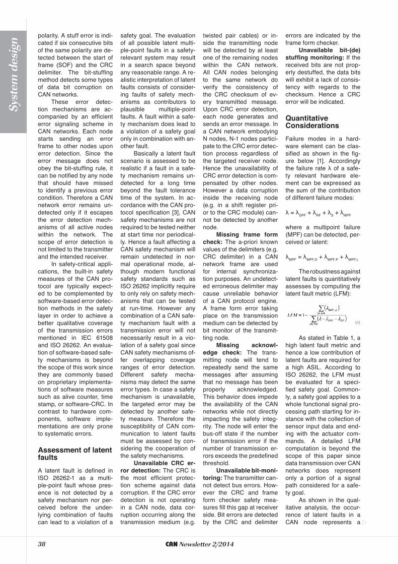
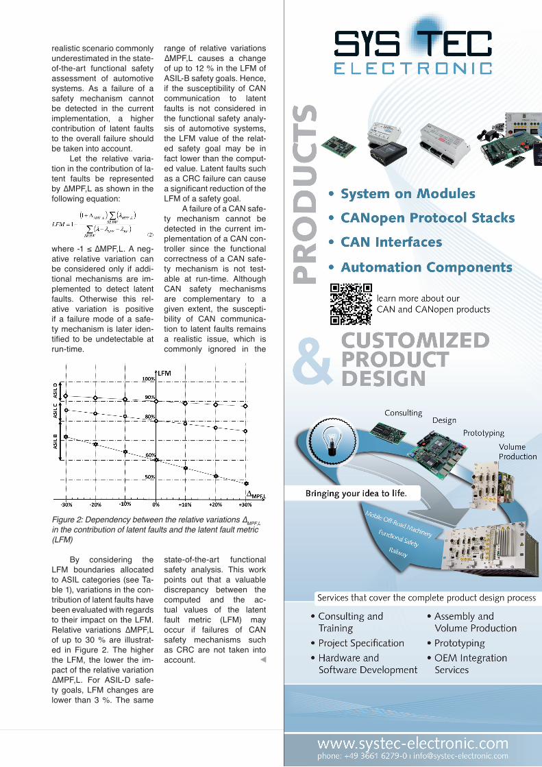
By considering the LFM boundaries allocated to ASIL categories (see Ta-ble 1), variations in the con-tribution of latent faults have been evaluated with regards to their impact on the LFM. Relative variations ∆MPF,L of up to 30 % are illustrat-ed in Figure 2. The higher the LFM, the lower the im-pact of the relative variation ∆MPF,L. For ASIL-D safe-ty goals, LFM changes are lower than 3 %. The same
range of relative variations ∆MPF,L causes a change of up to 12 % in the LFM of ASIL-B safety goals. Hence, if the susceptibility of CAN communication to latent faults is not considered in the functional safety analy-sis of automotive systems, the LFM value of the relat-ed safety goal may be in fact lower than the comput-ed value. Latent faults such as a CRC failure can cause a significant reduction of the LFM of a safety goal.
A failure of a CAN safe-ty mechanism cannot be detected in the current im-plementation of a CAN con-troller since the functional correctness of a CAN safe-ty mechanism is not test-able at run-time. Although CAN safety mechanisms are complementary to a given extent, the suscepti-bility of CAN communica-tion to latent faults remains a realistic issue, which is commonly ignored in the
state-of-the-art functional safety analysis. This work points out that a valuable discrepancy between the computed and the ac-tual values of the latent fault metric (LFM) may occur if failures of CAN safety mechanisms such as CRC are not taken into account.
Figure 2: Dependency between the relative variations ∆MPF,L in the contribution of latent faults and the latent fault metric (LFM)