N 3 DTIC · multiple-hit test is a severe test, but automatic weapons and fragmenting munitions are...
85
I1C FILE COPY , NSWC TR 89-356 HAZARD CLASS/DIVISION 1.6: ARTICLES CONTAINING EXTREMELY INSENSITIVE DETONATING SUBSTANCES (EIDS) N BY MICHAEL M. SWISDAK° JR. rN RESEARCH AND TECHNOLOGY DEPARTMENT N DTIC 1 DECEMBER 1989 3 ELE 0 TE0 Approved fot pubhc reW(e w, dititibution is unhm ted on NAVAL SURFACE WARFARE CENTER Dahlgren, Virginia 22448,5000 Silver Spring, Maryland 2090.5000 1('b
-
Upload
truongcong -
Category
Documents
-
view
217 -
download
0
Transcript of N 3 DTIC · multiple-hit test is a severe test, but automatic weapons and fragmenting munitions are...
I1C FILE COPY ,
NSWC TR 89-356
HAZARD CLASS/DIVISION 1.6: ARTICLESCONTAINING EXTREMELY INSENSITIVEDETONATING SUBSTANCES (EIDS)
N BY MICHAEL M. SWISDAK° JR.
rN RESEARCH AND TECHNOLOGY DEPARTMENT
NDTIC
1 DECEMBER 1989 3 ELE 0TE0
Approved fot pubhc reW(e w, dititibution is unhm ted
on NAVAL SURFACE WARFARE CENTERDahlgren, Virginia 22448,5000 Silver Spring, Maryland 2090.5000
1('b

NSWC TR 89-356
HAZARD CLASS/DIVISION 1.6: ARTICLESCONTAINING EXTREMELY INSENSITIVE
DETONATING SUBSTANCES (EIDS)
BY MICHAEL M. SWISDAK, JR.RESEARCH AND TECHNOLOGY DEPARTMENT
Acv-inFop,FIS- CRA&I0I W)( lAb
1 DECEMBER 1989 0.
Av,.o [)ih I t of, P
Apptoved fo pulic rise; d ibuuw is unrmited,
NAVAL SURFACE WARFARE CENTERDaWgren. Virginia 2244-S000 s Silver Spring. Maryland 20903.5000

NSWC TR 89-356
FOREWORD
Thi s task was performed for the Department of Defense Explosives SafetyBoard (DDESB), Code KT, under the cognizance of R. Sawyer and J. Ward.
The author wishes to acknowledge the following people in the performance ofthis task: (1) D. Tasker for the calibration of the Expanded Large Scale Gap Test(ELSGT) and the performance of the ELSGT on Composition B and PBX-9502;(2) D. Crabtree for the performance of the majority of the substance testingonComposition B and PBX-9502; (3) C. E. Coghill for the performance of the SUSANTest on the French explosives (B3003, B3103, Octarane 86A); (4) R. Bernecker,C. Dickinson, and D. Price for their insights and comments during the developmentof the test protocol; (5) the Air Force Inspection and Safety Center (AFISC), theMilitary Airlift Command (MAC) and the personnel at Ramstein Air Force Base,Germany, for help in shipping explnsive samples to and from France; and (6) the staffat the DDESB for allowing their files to be searched for information on the history ofClasalDivision 1.6 materials.
The mention of proprietary items or company names in this report is fortechnical information purposes only. No endorsement or criticism is intended.
Approved by:
KURT F. MUELLER, HeadEnergetic Materials Division
i/i i

NSWC TR 89-356
CONTENTS
Chapter az
1 INTRODUCTION ........................................... 1-1
2 HAZARD CLASSIDIVISION 1.6 TEST PROTOCOL ............ 2-1INTRODUC1ION ................................... . 2-1
3 SUBSTANCE TESTING ................................... 3-1
REFERENCES .............................................. 4-1
DISTRIBUTION ............................................ (1)
Anuendices RAre
A EXCERPTS FROM DOD 6055.9-STD (CHANGE 2 10/28/88) ..... A-1
B EXPANDED LARGE SCALE GAP TEST (ELSOT)CALIBRATION .......................................... B-1
C CLASS/DWISION 1,6 TEST PROTOCOL ...................... C-1D EIDS CAP TEST ............... t............................. D-1
E EIDSGAP TEST ............................................ E-1
F SUSAN TEST RESULTS .................................... Fl1
G EIDS BULLET IMPACT TEST ............................... G-1
H EIDS EXT7ERNAL FIRE TEST ................................ H-i
I EMS SLOW COOKOFF TEST ................................ 1-1
ii/iv

NSWC TR 89-356
TABLES
* Table Page
-. 3-1 HAZARD CLASS/DIVISION 1.6 TEST RESULTS--SUMMARY. 3-2
v

NSWC TR 89-356
CHAPTER 1
INTRODUCTION
The interest in Hazard Class/Division 1.5 within the Departmient of Defense(DOD) and the Department of Energy (DOE) dates back to the)Ate 1970s. In its 1977revision of its document on the Transport of Dangerous Good0'the United Nations(UN) Group of Experts on Explosives defined "very insensitive explosives" andlimited them to Type B and E blasting agents,(as defined in Reference 1).
In June 1979, Air Force requested the Department of Defense ExplosivesSafety Board (DDESB) concurrence/approval for aDepartment of Transportation(DOT) hazard classification of 1.5L for Triaminotrinitrobenzene (TATB) and variousTATB formulations. This represented the first instance of the UN Class 1.5 designa-tion being sought for a DOD/DOE explosive. Shortly thereafter, the DDESB raisedseveral techncal questions regarding the apllication of the 1.5 classification tomilitary n~~teria s. In order to resolve theseAquestions, they proposed the followingsolution. )
.. It is suggested that the objective development of criteria for HazardDivision 1.5 could best be accomplished by a tri-Service working groupwith recognized expertise in evaluating explosive properties, such asthe Joint TechnicalCoordinating Group for Munitions DevelopmentWorking Party for Explosives, in cooperation with Service safety officerepresentatives.
The DDESB further requested the Joint Technical Coordinating Group/WorkingParty for Explosives (JTCG/WPE):3
1. Review the UN Classification scheme for 1.5 materials and determine itsapplicability to DOD/DOE materials
2. Define the levels of sensitivity, response to stimuli, and effects onsurroundings for Division 1.5 storage/operational applications
3. Recommend the minimum probabilities and confidence levels to beaccepted in a Division 1.5 testing scheine
4. Express opinions as to whether sensitivity, reaction effects, or both shouldbe the criteria used for reducing/eliminating quantity-distancerequirements.
In February 1980, the Joint Technical Coordinating Group for MunitionsDevelopment: Working Party for Explosives (JTCG/MD/WPE) established an AdHoc Study Group to advise the DDESB and to determine a tri-Service position on theHazard Classification 1.5 for explosive materials (high explosives, propellants,
1-1

NSWC TR 89-356
pyrotechnics, etc.) and munitions containing these materials. The terms of referenceor this group included:
1. Define the criteria to be used to establish the 1 .5 Classification Criteria formilitary explosives and munitions
2. Study other issues arising fron the introduction of the UN classificationscheme, as required.
The official title of the Group was the Ad Hoc Study Group on Criteria forInsensitive Explosives Hazard Classification Division 1.5. The members of the AdHoc Group and their filiations were:
Mr. F. West Air Force ChairmanDr. L. Elkins Air Force RecorderMr. L. Avrami Army MemberMr. E. Demberg Army MemberMr. M. Swisdak Navy MemberDr. C. Dickinson Navy MemberMr. E. James DOE MemberMr. M. Urizar DOE Member
After much discussion and deliberation, the Group reached a consensus on a testprotocol for Division 1.5 substances and recommended them back to the DDESB on
4 April 1980.
The Secretariat at the DDESB indicated that they supported the testprocedures for classifying insensitive high explosives substances as HazardDivision 1.5. They further recommended that for hazard classification testing ofarticles (note: emphasis is theirs) containing Hazard Division 1.5 substances, therequirements of STANAG 41234 and TB 700-26 should be followed. At the 279thMeeting of the DDESB, the report of the Ad Hoc Study Group was accepted withminor changes. These changes included a redefinition of Hazard Division 1.5.
This division comprises Class/Division 1.1 explosives substanceswhich, although mass detonating, are so insensitive that there isnegligible probability of initiation or transition from burning todetonation in transport or storage.
The DDESB, however, still desired a well-defined test protocol which could be usedfor articles--not just substances.
In November 1980, the WPE requested additional comment and suggestionsfrom various DOD and DOE groups concerning Class/Division 1.5 substances andmunitions. In January 1981, comments were received from the Los Alamos ScientificLaboratory. Included among these was the following concerning testing of 1.5articles:
Attack of munitions, and perhaps even bulk HE, by small arms orfragments would seem to be a real concern. I believe an IHE itemshould not detonate, or even deflagrate with enough energy to detonateadjacent items, in a realistic multiple-hit bullet or fragment test. Amultiple-hit test is a severe test, but automatic weapons andfragmenting munitions are a realistic threat. The first hit in an HE
1-2

NSWC TR 89-356
charge causes damage and reduces charge density, effectivelyincreasing HE sensitivity. The second hit is then far more likely tocause detonation.
On 23 January 1981 a DDESB memorandum for the three Service BoardMembers summarized the status of Hazard Classification for Insensitive Explosives.The following is quoted from that memorandum:
... The 279th and 281st meetinps of the Board... addressed hazardclassification criteria for insensitive explosives. At the 279th meeting,the Board accepted the JTCG Ad Hoc Study Group report ... withcertain changes and, in addition, established an interim hazarddivision 1.5 quantity-distance standard. At the 281st meeting, theBoard addressed validation tests information furnished by the Ad HocStudy Group and the Department of Energy on certain TATBformulations and comparative explosives. Included were results oftests which were not addressed ... (e.g., multiple bullet impact test). Itwas stated that the multiple bullet impact test can give different,sometimes more violent, results than the single bullet impact test. Thequestion was raised, but not resolved, as to its applicability in the testscheme for evaluating Division 1.5 explosives.
On 16 March 1981, the Ad Hoc Study Group was disestablished. The VVFE thenconvened a special meeting for the purpose of reviewing and modifying as necessarythe WPE recommendations to the DDESB and to prepare a final WPE position on thismatter. The following is a list of participants at that meeting:
R. Sawyer DDESBW. Queen DDESBL. Elkins Air ForceR. McGuire DOEM. Urizar DOEL. Avrami ArmyR. Beauregard NavyA. Amster NavyL. Roslund NavyC. Dickinson NavyM. Swisdak NavyH. Adolph NavyC. Dahn Private Consultant
As a consequence of this meeting, the VVPE forwarded to the DDESB a set ofcomments on modificationsto its proposed test scheme. One of the comments is ofparticular importance and is quoted below:
... UN hazard classification division 1.5 was devised for commercialblasting agents which are insensitive because of large criticaldiameters. A separate classification 1:X (or 1. some other designation)is recommended for military explosives which have relatively smallcritical diameters but still are insensitive. These two types ofinsensitive explosives respond differently to hazard stimuli and shouldnot be covered in one category... . The division 1.X classification wouldapply and be restricted to materials passing an appropriate test scheme
1-3
NSWC TR 89-356
and criteria, and having the same physical and chemical stateproperties as when tested.6
During testing of the warhead for the Ground Launched Cruise Missile(GLCM), the Air Force recommended the following tests for Class 1.5 articles:
Impact Test (Sled Track or Pull Down)BonfireBullet Impact
In addition to these tests, they had run the following tests:
Forty-Foot DropPropagation TestShaped ChargeThermal Stability Test
On 19 January 1982, during the 283rd meeting of the DDESB, HazardClass/Division 1.5 substance and article testing was again discussed. Duringdiscussions at this meeting, the bullet impact test was discussed for articles.Mr. Queen (of the DDESB Secretariat) indicates, "We would like to call yourattention here to the bullet impact test and how we have stipulated that it bePerformed. And that we would only use 50 caliber bullets...." Later in the sameaiscussion Mr. Queen states, ".. . Now again, let me emphasize that we're talkinghere about not the substance, but rather ammunition items that contain thesubstance .... I would call your attention to the last one where we are indicating ourconcern about possible effects of powdering or whatever in the event of multiplebullet impact. 'We expect three round burst to be fired into this item for a minimumof three orientations./
On 28 January 1982, at the 284th meeting of the DDESB, modifications to theDOD Explosives Safety Standards were approved. Included at this meeting was adiscussion ofterminology. Quoting from the minutesof the meeting"... 1.5 has itsorigin in transportation circles (the UN requirements for transportation), that itapplies only to substances (namely, blasting agents) and that it really adds toconfusion when you start talking about articles (am-munition) in the same manner.We feel that the term insensitive high explosive, as we proposed, avoids this andachieves the objective that we were trying to achieve. This does require changing theinterim criteria but only in an incidental way; i.e., removing references to 1.5....'This position, and a discussion of the changes to the DOD standard are discussed inaDDESB letter. This protocol for insensitive high explosive (IRE) materials isthe one currently appearing in the DOD 6055.9-STD.11 The protocol, shown asAppendix A in this document, consists of the following:
SCREENING TESTS
Impact TestFriction TestDifferential Thermal Analysis (DTA)Small-Scale BurnSpark Tests
1-4

NSWC TR 89-356
QUALIICATION TESTS FOR IHE
Critical DiameterCap TestCard Gap TestSlow CookoffExternal FireSusan TestBullet Impact
QUALIATION TESTS FOR IqE AMMUNITION
Sled TestBonfirePropagationSlow CookoffMultiple Bullet
The test procedures for each test were referred to existing DOD documents whichdescribed the tests in more detail. The pertinent sectionsof the DOD protocol arereproduced in Appendix A.
DOD 6055.9-STD is a United States document with applicability limited toDOD agencies and their contractors. In order to achieve a wider distribution anda plicbility the DDESB, as technical consultant to the DOT, continued to urge itsadoption by the UN with the protocol incorporated into the document"Recommendations on the TRANSPORT OF DANGEROUS GOODS Tests andCriteria."
In 1983, the DDESB petitioned the DOT for the establishment of a regulationfor the transport of IHE substances and HE ammunition articles by or for acomponent of the DOD. The DDESB further proposed that the test protocolincorporated on DOD 6055.9-STD be included in Title 49, Part 149 of the Code ofFederal Regulations (CFR).
In 1986, the United States (US) agreed to make a formal proposal to the UNGrouV of Experts on Explosives; this proposal concerned the inclusion of articles inDivision 1.5. In April 1986, a draft of this proposal was transmitted to the USrepresentative at the DOT. Itwas formally proposed at the 26th session of the Groupof perts on Explosives held in August 196 The French made detailed coummentsand recommended several additions and changes. The test series, as modified by theFrench, was found to be generally acceptable by the US representative. The revisedtest protocol was prc<:nted and discussed at the 27th seasion of the Group of Expertson Explosives held 17 to 21 August 1987. As a result of the discussions at thismeeting, the DDESiP, in late 1987, requested that the Naval Surface Warfare Center(NSWC) review the existing protocol for Hazard ClassDivision 1.5 and IKEmaterials. This review was to include, but was not limited to:
1. The coordination and the obtaining of recommendations of changes to theprocedures with/from the appropriate Service hazard classification testexperts
2. Conversion of US test weight and measure specifications into theinternational system of units (SI)
1.5

NSWC TR 89-356
S. Conversion of US test materials/standard specifications to internationalterminology.
The tests included in the procedures at that time included:
1. Critical Diameter Test2. Cap Test3. Gap Test4. Susan Test5. Friability Test6. Bullet Impact Test7 External Fire Test8. Slow CookofffTe't9. Stack Test
Items I through 8 were to be performed on the substance; items 6 through 9 were tobe performed on the article containing that substance tested in 1 through 8. At thistime, there were two Gap test series in the protocol. The first was proposed by the USand the second by the French. The US tests consisted of the standard Large ScaleGap Test (LSGT) and the Expanded Large Scale Gap Test (ELSGT)I depending uponthe critical diameter of the substance. The French Gap test also consisted of twotests--the test described in Section 2a (iv) of Reference 1 and the US ELSOT. Thechoice of which test was again dependent upon the critical diameter of the substance.The friability test was a French test which could be substituted for the US BulletImpact and Susan Tests.
Within the US, the representative to the UN Committee of Experts on theTransportation of Hazardous Materials is the DOT. Any test procedures that are tobe submitted to the UN must be approved and submitted by reprontatives of thisorganization. In early 1988, discusons were held between representatives of theDOT, the DDESB, and NSWC concerning the 1.5 test procedures. As a resultof theseand other di sussions, certain tests were sunplified and one, the critical diametertest, was eliminated.
Further discussions with the French simplified the Gap Test procedures. Withthe elimination of the Critical Dianeter Test, it was decided that only one Gap TestProcedure would be requimred-Ahe ELSGT. Further discussions Rt thepas/fa ilcriterion for this test at 276 US cards (2.76 inches) or 70 min of polymethylmethacrylate (PM JA). NSWC was also taskt 'to develop a "calibration curve" forthis new Gap Test. The work has been completed nd is reported in detail inReferences 12 and 13. Appendix B contains P summary of the required calibrationinformation.
At a meeting of the UN Committee of Experts during 1988, it was decided thatthese new materials and articles really should be clearly distinguished fromcommercial blasting agents, which are also classified as 1.5 materials. To accomplishthis, a new class/divisioni was established: Class/Division 1,6 for articles whichcontain "Extremely Insensitive Detonating Substances (EIDS)." Atthe s-imemeeting, the US/French test protocol was accepted and will be included in the nextrevision of Reference 1.
1.6

NSWC TR 89-356
CHAPTER 2
HAZARD CLASS/DIVISION 1.6 TEST PROTOCOL
The following is quoted from the Introduction to Test Series 7 for Class/Division1.6 materials. The figure and paragraph numbers refer to sections found inReference 1.
INTRODUCTION
45.1 The question, "Is the result an extremely insensitive explosive article?"(Fig. 1,3, box 40) is answered by Series 7 Tests and any candidate for Division 1.6mustpass all the tests ha ed,Ts 7(a) to 7(k) shown in paragraphs 45.2 to 45.11pernut the classification of articles of Division 1.6 compnrng Extremely InsensitiveDetonating Substances (EIDS).
45,2 Mae 7(a) t st: Shock test to determine the sensitivity to detonation by astandard detonator.
e.g., Test 7(a) EIDS Cap Test.
45.3 ,Tye 7(b) test: Shock test with a defined booster and cofinement todetermine the nsitivity to shock.
e.g.. Test 7(b) ElIS Gap Test.
45.4 Type 7(c) test: Test to determine the sensitivity of the explosive substance todeteriorate uder the effect of an impact.
e,g., Test7(c)(i) Susan ImpactTestTest 7(Oii) Friability Test
45.5 tm.n7jd1 tst: Test to determine the degree of reaction of the explosivesubstance to impact or penetration resulting from a given energy source.
e.g., Test 7(d)(i) EIDS Bullet lmpact TestTest 7(dXii)Friability Test
45.6 Typ 4!t: Tet to determi ne the reaction of the explosive substance to anexternal ie when the material is confined.
e.g., Test 7(e) EIDS External Fire Test.
2-1

NSWC TR 89-356
45.7 7 : Test to determine the reaction of the explosive substance in anenvironment in which the temperature is gradually increased to 365C.
e.g., Test 7(W) EDS Slow Cookoff Test.
45.8 Tv 7gt: Test to determine the reaction to an external fire of an articlewhich is in the condition as presented for transport.
e.g., Test 7(g) Division 1.6 Article External Fire Test.
41.9 .Tse 7(h) test: Test to determine the reaction of an article in an environmentin which thetemperature is gradually increased to 365°C.
e.g., Test 7(h) Division 1.6 Article Slow Cookoff Test.
45.10 yDp (ltst: Test to determine the reaction of an article to impact orpenetration result g from a given energy source.
e.g., Test 7(j) Division 1.6 Article Bullet Impact Test.
45.11 Ty 7(k) test: Test to determine if an article will detonate a similar itemSAjacent to it which is in the condition as presented for transport.
e.g., Test 7(k) Division 1.6 Article Propagation Test.
45.12 A substance intended for use as the explosive load in an article of Division1.6, should be tested in accordance with Test Series 3 and 7. Test Series 7 should beconducted in the form (i.e., composition, granulation, density, etc.) in which it is to beused in the article.
45.13 An article being considered for inclusion in Division 1.6 should not undergoTest Series 7 testing until after its explosive load has undergone Tests 7(a) through7(W) to determine whether it is an EIDS.
The explosive load is not an EIDS if a "+" is obtained in any one of Tests 7(a)through 7(f).
+ means that the substance is too sensitive- means that the substance is not too sensitive.
To determine if the article with an EIDS load is a Division 1.6 article, Tests 7(g)through 7(k) are performed. These tests are applied to articles in the condition andform in which they are offered for transport, except that non-explosive componentsmay be omitted or simulated if the competent authority is satisfied that this does notinvalidate the results of the tests.
The question in Box 40 is answered "NO" if a "+ "is obtained in any one ofTests 7(a) through 7(k).
The entire test protocol including Figure 1.3 (which is referred to above) ispresented in Appendix C.
2-2

NSWC TR 89-356
CHAPTER 3
SUBSTANCE TESTING
As part of the agreement between the US and tht other members of theCommittee of Experts on the Transport of Hazardous Materials, the US agreed totake at least two materials through the entire EIDS test procedure. The twomaterials chosen were Composition B (a melt cast material consisting of 60 percentRDX and 40 percent TNT with 1 percent wax added) and PBX-9502 (a pressedmaterial consisting of 95 percent TATB and 5 percent KEL-F). The Composition Bwas chosen as representative of many of the current melt-cast systems and wasexpected to fail almost every test. The PBX-9502 was chosen to represent the newinsensitive, plastic bonded explosives, and was expected to pass every test. Inaddition, the French would submit three of their materials to the protocol. TheFrench materials were:
1. Octorane 86A (86 percent HMX, 14 percent inert binder)
2. B3003 (80 percent HMX, 20 percent energetic binder)
3. B3103 (51 percent HMX, 30 percent energetic binder, 19 percentaluminum,
The French would submit their materials to the friability test, and the US wouldsubmit theirs to the Bullet Impact and the Susan Tests. In addition, samples wereexchanged between the US and France. The Friability Test would be performed onthe US materials and the Susan Test performed on the French materials. The detailsof the testing and the results obtained are presented in Appendices D through I. Theresults are summarized in Table 3-1. The full test results for the French materialswere not available at the time of publication of this report. The French results will,ultimately, be published in a French report.
Three other US materials (developed under contract to the US Air Force) havebeen tested to an older version of the test protocol. These three materials are:
1. AFX-920 (22 percent RDX, 33 percent HBNQ (high bulk nitroguanidine),15 percent EDDN, 14 percent aluminum, and 15 percent binder)
- 2. AFX-930 (32 percent RDX, 37 percent HBNQ (high bulk nitroguanidine),15 percent aluminum, 9 percent binder, and 7 percent plasticizer)
3. AFX-931 (32 percent RDX, 37 percent AP (Ammonium Perchlorate),15 percent aluminum, 9 percent binder, and 7 percent plasticizer)
A careful examination of the testing protocol used far these materials reveals nosubstantial differences between it and the currently accepted protocol. For thisreason, these materials have also been included in Table 3-1.
3-1

NSWC TR89-356
- - - - - -
E.
E
"4')TI mE- -
+ En+ + I
u - -4-
+ I - - '.~ I I3B2

NSWC TR 89-356
REFERENCES
1. Recommendations on the TRANSPORT OF DANGEROUS GOODS: Tests andCriteria, United Nations Publication, MSG/ 10/11, NY, 1986.
2. DDESB ltr of 6 Nov 1979, Subj: "Explosives Hazard Classification forTriaminotrinitrobenzene (TATB) Formulations."
3. DDESB ltr of 5 Feb 1980, Subj: "Explosives Hazard Classification forTriazinotrinitrobenzene (TATB) Formulations."
4. NATO Standard National Agreement STANAG 4123 (Edition 2), "Methods toDetermine and Classify the H'azards of Ammunition," Oct 1978.
5. Defense Logistics Agency Regulation (DLAR) 8220.1 (TB 700-2,NAVSEACNST 8020.8, TO 11 A-1-47), "Department of Defense ExplosiveHazard Classification Procedures," Sep 1982.
6. Joint Technical Coordinating Group For Munitions Development: WorkingParty For Explosives ltr, Serial 64EIHGA 114 of 4 Sep 1981, Subj: "HazardClassification For Insensitive Munitions and Explosives."
7. Minutes of the 283rd DDESB, Meeting.
8. Minutes of 284h DDESB Meeting.
9. DDESB ltr of 24 Feb 1982, Sub): "Report of the 284th Meeting of theDepartment of Defense Explosives Safety Board."
10. Dgepa A - .nt of Defense Anumunition and Ex~losives Safety Standards,DDD 6055.9-STD, First Amendment (Change 2), 28 Oct 1988.
11. Liddiard T P and Price, D., The Expanded Large Scale Gap Test,NSWC Tik g"-2, Mar 1987.
* 12. Tasker, D). and Baker, R., "A New Unbiased Method For Analyzing StreakData, The Calibration of the NSWC Expanded Large Scale Gap Test (ELSGGT),"paper presented at the American Physical Society Meeting, 1989.
1.3. Tasker, D. and Baker, R., An Explosive Calibration of the NSWC Expanded
4-1

NSWC TR 89-356
APPENDIX A
EXCERPTS FROM DOD 6055.9-STD)
(Change 2 10/28/88)
A- 1/A-2
NSWC TR 89-356
Jul 84DoD 6055.9-STD
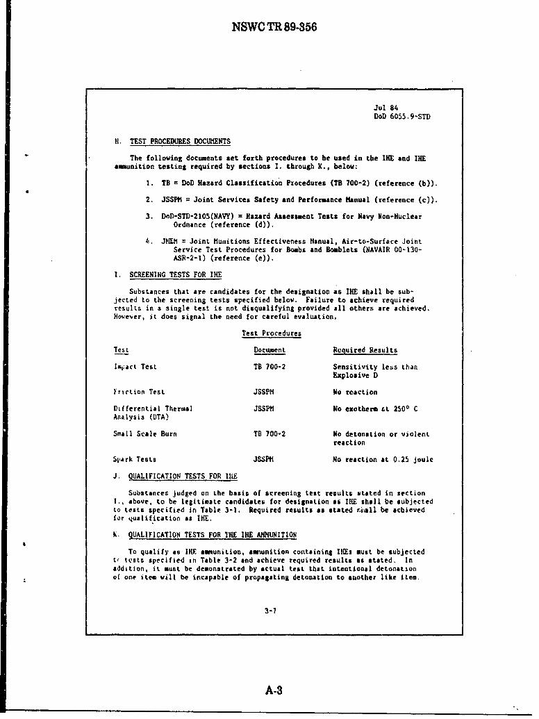
H. TEST PROCEDURES DOCUMENTS
The folloving documents set forth procedures to be used in the IHE and IHamunition testing required by sections I. through K., below:
1. TB = DoD Hazard Classification Procedures (TB 700-2) (reference (b)).
2. JSSPM = Joint Services Safety and Performance Manual (reference (c)).
3. DoD-STD-2105(NAVY) = Hazard Assessment Tests for Navy Non-NuclearOrdnance (reference (d)).
k. JHEM = Joint Munitions Effectiveness Hanual, Air-to-Surface JointService Test Procedures for Bombs and Boumblets (NAVAIR 00-130-ASR-2-1) (reference (e)).
I. SCREENING TESTS FOR IRE
Substances that are candidates for the designation as IHE shall be sub-jected to the screening tests specified below. Failure to achieve requiredresults in a single test is not disqualifying provided all others are achieved.However, it does signal the need for careful evaluation.
Test Procedures
Test Document Required Results
Imiact Test TB 700-2 Sensitivity less thanExplosive D
Friction Test JSSPH No reaction
Differential Thermal JSSPtI No exotherm zt 2500 CAnalysis (DTA)
Small Scale Burn TB 700-2 No detonation or violentreaction
Spark Tests JSSPH No reaction at 0.25 joule
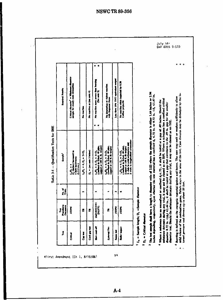
J. QUALIFICATION TESTS FOR IK1E
Substances judged on the basis of screening test results stated in section., above, to be legitimate candidates for designation as IHE shall be subjected
to tests specified in Table 3-I. Required results as stated riiall be achievedfor qualification as IKE,
K, QUALIFICATION TESTS FOR THE IRE AhUITION
To qualify as 111 amunition, amwnition containing lIfs must be subjectedte tests specified in Table 3-2 and achieve required results as stated. Inaddition, it must be demonstrated by actual test that intentional detonationof one item will be incapable of propagating detonation to another like item.
3-7
A-3
NSWC TR 89-356
July 4.-DnO 6055 9-STi)
d~
iirt Ame w (C .4/9/6
' A-4-j i
! t. m,, tE'..' ?I,
I-
A-4

NSWC TR 89-36
z 0;- of
IL 0
I z
C-
v~~-1b c Cg.~ g. ~ oil
I't c-V O C
8 - --
A-5

NSWC TR 89-356
Jul .4#DoD 6055.9-ST1
Table 3-4 - IKE and IKE Anwunition HazardClassification/Compatibility Groups
IRE bulk 1.5D
IHE Loaded projectiles and/or 1.5Dwarheads w/o fz s orwith IHE Fuzes
Iso
IHE Fuzes 1. 4D
IHE loaded projectiles and/or 1.3C/l.2C3
warheads w/ 1.3 propellingcharges and without 5uzesor with IHE Fuzes I
IHE loaded projectilel and/or 1.21 3
,4
warheads with non-INEFuzes and without 1.3propelling charges
IKE loaded projectile Ind/or 1.2E
3 .4
warheads with non-IKEFuzes and with 1.3propelling charges
it, THE Fuzed" means that the fuze has an JIMI h-oter with an out-of-line
non-IRE explosive and two or more independett safety features. The fuze Mustbe certified as invulnerable to accidental detonation of the warhead.2Fuzed configuration must be tested for propagation,
3 Unit risk may be justified on a case-by-c4se basis.
4Fuze must have two or more independent safety features and independently
classified Group D.
NOTE: When stored with compatible items of other Q-D classes, the mostre'rictive Q-D class will apply.
*Firat Amendment (Ch 2, 10/28/88)
3-12
A-6

NSWC TR 89-356
Oct 28, 88DoD 6055.9-STD
H. CLASS/DIVISION 1.5 Q-D DETERMINATIONS
I. Scope. This section establishes Q-D stindards for amunition andexplosives that have been hazard classified Class/Division 1.5 as a result ofhazard classification testing under requirements in Chapter 3, sections Ithrough K.
2. Quantity of Explosives. The veight of explosives shall include asuitable addition for propellant or pyrotechnic components if they contributeto the reaction. A maximum of 500,000 lbs shall be permitted at any one location.
3. Q-D Application
a. Quantity-distance separations for Class/Division 1.5 ammunition andexplosives shall be based on current Class/Division 1.2, 1.3, and 1.4 tablesdepending on the storage location and configuration. This information isdetailed in Table 9-28 and the following paragraphs.
Table 9-28 - Q-D Criteria for Class/Division 1.5 Components andAssemblies with other Class/Division Components
Configuration
Location Explosive Amunition
Bulk Non-INE Fuxed2 Unfuzed or vith IRE Fuze',4
with or without 1.3 propelling ithout 1.31.3 propelling charae chsrge propelling charge
Igloo Div 1.3 Div 1.23 Div 1.3 Div 1.3/1.4 5
Storage
All Div 1.3 Div 1.23 Div 1,3 Div 1.31
Others
IUnlt riuk minimum fragment distance applies, unless excepted on a case-by-casebasis by the DDESS.
2Fuzed configuration must be tested for propagation.
3Unit risk may be justified on a case-by-case basis.
4"INE Fuzed" means that the fuze has an I E booster with an out-of-line non-IREexplosive and two or more independent safety features.
5Clas/Division 1.4 applies for items packed in non-flamable pallets or packing,stored in earth-covered steel or concrete arch "gazines when acceptable to theDoD Component &ad the DDESB on * site-specific basis.
b. Inhabited building distances for bulk Class/Division 1.5 explosives& hall be based on Table 9-10. column 2. Inhabited building distances forClass/Division 1.5 amunition shall be the greater of Tables 9-6 through9-10, column 2 distances as applicable, or the unit risk hazardous fragmentdistance, as specified by note I in Table 9-28.
9-59
A-7

NSWC TR 89-356
Oct 28, 88DoD 6055.9-STD
c. Public traffic route distances for bulk Class/Division 1.5 explosiveshall be based on Table 9-10, column 3. Inhabited building distances forClass/Division 1.5 ammuition shall be the greater of Table 9-6, column 2throush 9-10 distances, as applicable, or the unit risk hazardous fragmentdistance as specified by note I in Table 9-28.
d. Intraline distances for Class/Division 1.5 explosives shall be based onTable 9-10, column 4. Intraline distances for Class/Division 1.5 ammunitionshall be the greater of Tables 9-5 through 9-10, column 4 distances, asapplicable or 50 percent of the unit risk hazardous fragment distances, asspecified by note I in Table 9-28.
e. Aboveground magazine dictances for Class/Division 1.5 explosives shallbe based on Table 9-10, column 4. Aboveground magazine distances for Class/Division 1.5 ammunition shall be based on Tables 9-6 through 9-9, column 5, asapplicable or Table 9-10, column 4 with a 200 ft minimum when there is no inter-vening barricade.
f. Any special storage configuration and siting approved for Class/Division2.1 ammunition or explosives may be used for the storage of like quantities ofClass/Division 1.5 ammunition or explosives, respectively.
4, Colocation/Separation Requirements
a. Class/Division 1.5 amunition and explosives that are located with orlocated at less than magazine distance from ClassDivision 1.1 or 1.2 smunitionand explosives shall be treated as Class/Division 1.1 for Q-D purposes.
b. Class/Division 1.5 amunition and explosives located with Class/Division1.3 or 1.4 ammunition and explosives shall be treated as Class/Division 1.3 forQ/D purposes with a 500,000 lb maximum limit.
I. HILITARY I AORING DOG EXPLOSIVES SEARCH TRAINING
I. General. Realistic and effective training of military working dogs (Me D)to detect explosives that have been hidden in various public places requires thatsimulated searches are conducted in areas that are regularly inhabited by people.It is essential that the training is conducted so that all persons unrelated totraining of the dogs are not exposed to the hazards associated With an accidentalexplosion of a training sample.
2. Operation On Explosives Used for Training, Because of the dangers in-herent in explosives operations including handling explosives, cutting or dividingexplosive training aids, removing explosives froo the shipping and storage con-tainer, and repackaging explosives into other containers, these operations shallbe conducted by qualified personnel only in facilities that meet the Q-D and otherrequirements of this Standard.
3. Storing Explosives Training Aids. Explosives must be stored in facilitiesthat met the Q0 and other requirements of this Standard.
4. Explosives Detection Proficiency Training Safety Procedures. Personsunrelated to the training of the dogs must not be exposed to the hazards associ-sted with an accidental explosion of the training sample. Therefore, at thetraining site:
A-8

NSWC TR 89-356
APPENDIX B
EXPANDED LARGE SCALE GAP TEST (ELSGT) CALIBRATION
Prepared by
Douglas G. Tasker
B-1

NSWC TR 89-356
(UM:h PISMAn Int ape)
GATHIC(N8EW ______ $CEWT (m......)I1VT) +01 *+025* '40.5W *.0.751
0.00 10.06 10.69 10.81 10.7410.00 10.67 1l.5 10.52 10.43
11.00 10.35 1026 1021 10.1412.00 10.06 too 904OA13.00 0.79 9.73 9.66 0.6114.00 9.55 0.49 9.43 9.3715.00 0.31 0.26 9.2 9.15MO.O 0.10 0.04 6.9 6.0317.00 *As8 8.49 V7 9.7310.00 6.67 8.6 6.6 s.510.00 6.48 0.44 4.3 &2530.00 "I3 oil? &n2 Vs1
21.00 0.14 0.11 U.7 9.0322.00 4.00 7.06 7.63 7.0023.00 7.68 7.63 7.70 7.7624.00 7.72 7.60 7.68 7.6225.00 7.m 7.55 7.51 7.4126.00 7A4 7.40 7.37 7.3327.00 7.30 72m 723 7.193.00 7.16 7.13 7.A0 71.0620.00 7.m 7.00 07 &60430.0 "1I 416 sm6 am
31.00 6.79 6.77 V.4 0.7132.00 6.63 0.65 6.62 $A633-00. 6.5 6.84 051 04114.00 6.45 6.42 0.40 0.1135.00 G.84 6,32 0 O.2736.00 6.2$ 6.22 0.20 0.1s37.00 0.16 s.1 SIM 0.103.00 6.06 #.07 6.06 6.033.-00 601 9.49 UP? &IS40-00 6.62M 13 am
41.00 666 5.63 9,41 VV7Q-.00 5,77 6.76 &73 .0,7143,00 so0 6.0 W C"44-00 26 2 9.6' S*.$A43.00 E.6 FAd 5uM 416000 1$9 6.47 5.43 6.4447-00 6.42 5 * 634Woo 0 1. 61 620 127
44-0D 5Z 4.23 62 5205000 5.11 517 s1 if.614
51-00 1 811 al10l SooL2 00 C.og 6.07 S,09 I
4300 6.03 C4 So0 #4064-00 1.66 4.49 4.94 493
560401 440 to7 410mo00 4j" 4451 4.70 4.7697.00 47$ 414 4112 4.70oa00 4" 4.06 464 66, 2bOO 460 4.64 4.58 j .13
002 4" 4 2 -*
B-2

NSWVC TR 89-356
(NOM: Pesaw inGP@
GAP THIC1(NISS ONCFRE?' tvw ____
tI.4. 1+025* *O.60* *40.75,
41.00 441 41 4.3 4.3462.00 4.31 4.20 4.25 4.2463.00 4.22 4.19 4.17 4.1564.00 4.13 4.10 4.06 4.0568.00 4.02 4.O0 397 3.94Wo.o 3.91 3.88 &6 34367.00 3.00 3.70 3.75 3&7260.00 3.70 3.68 3.66 3.8344.00 3.61 3.59 3.67 3m570.00 sm5 3.51 3.46 3.43
71.00 3.43 3.41 3.39 5,3772.00 3.34 3.31 3.29 3.2671.00 323 320 3.16 3.s74.00 3.13 3.11 &.00 3.07'5.00 3.05 3.03 3.01 3.0071.00 2.96 2.9 2.96 2.9377.00 2.92 2.90 1-067$70.00 2.45 2683 2.00 2.7479.00 2.76 2.74 2.71 2.49
1000 266 26 1161 820
W1.00 2,51 2.5 213 2.514200 250 245 2.47 2.456300 244 2.43 2.42 2.410400 240 23 z.8 2.3705.00 234 2.35 334 2.336800 231 2.30 2 " 247it.00 2.24 2125 2z M22WOO0 220 219 2.11 2.116000 215 .t 2. 13 2.1 tW-00 2.1) 2.00 lob6 Ito?
0100 j 204 2.6 2.04 2 03
20W2 W202 201 00
6400 1.06 1,96 IV 1.04600 104 1.93 t.93 1.0403 1.901 1.00 1.100700 1.41 187 1 1.04" 00 11: 141 178 1.710 C-3 1-12 1.0 IM 1.4210000 1.17 162 IA
B-3

NSWC TR 89-356
APPENDIX C
CLASS/DIVISION 1.6TEST PROTOCOL
(as contained in the following United Nations documents)
ST/SG/AC.10/C.3/2 25 August 1989ST/SG/AC.10/C.3/R.19 9 May 1989ST/SG/AC.10/15/Add.1 17 January 1989ST/SG/AC.10/R.258 13 October 1988ST/SG/AC.!0/R.199 5 September 1988ST/SG/AC.10/C.1/20 25 August 1988ST/SG/AC.10/C.1/R.236 27 June 1988ST/SG/AC.10/C.1/18 30 September 1987ST/SG/AC.10/C.1/R.205 26 June 1987ST/SG/AC.10/C.1/16 25 August 1986ST/SG/AC.10/C.1/R.195 29 May 1986
Note: The actual composition of Composition B is 60 percent RDX and 40 percentTNT with 1 percent wax added. This correction will be made in futurerevisions of the protocol.
C-1

NSWC TR 89-356
TEST SERIES 7 FOR CLASS/DIVISION 1.6 ARTICLES
(Articles Containing Extremely Insensitive Detonating Substances (EIDS))
Test Test Test Name of Test Country of Section PageSeries Type Number Origin
7 INTRODUCTION 45
TESTS ON SUBSTANCES
7 (a) EDS Cap Test D/USA 46
7 (b) EIDS Gap Test USA 47
7 (c) (i) Susan Test USA 48
(ii) Friability Test F 49
7 (d) (i) EIDS Bullet USA 50ImpactTest
(ii) Friability Test F 49
7 (e) EIDS External UN 51Fire Test
7 (f) EIDS Slow USA 52CookoffTest
TESTS ON ARTICLES
7 (g) 1.6 Article E.ternal UN 53Fire Test
7 (h) 1.6 Article Slow USA 54Cookoff Test
7 (j) 1.6 Article Bullet USA 55Impact Test
7 (k) 1.6 Article Stack UN 56Test
C-2

NSWC TR 89-356
TEST SERIES 7
INTRODUCTION
45.1 The question, "Is the result an extremely insensitive explosive article?"(Fig. 1.3, box 40) is answered by Series 7 Tests and any candidate for Division 1.6mustpass all the tests listed. Tests 7(a) to 7(k) shown in paragraphs 45.2 to 45.11permit the classification of articles of Division 1.6 comprising Extremely InsensitiveDetonating Substances (ZIDS).
45.2 Tj 7(a) test: Shock test to determine the sensitivity to detonation by astandard detonator.
e.g., Test 7(a) EIDS Cap Test.
45.3 T-Vve 7(b) test: Shock test with a defined booster and confinement todetermine he sensitivity to shock.
e.g., Test 7(b) EIDS Gap Test.
45.4 -7(c) test: Test to determine the sensitivity of the explosive substance todeteriorat under the effect of an impact.
e.g., Test 7(c)(i) Susan Inpact TestTest 7(c)(Ui) Friability Test
45.5 Type 7e test: Test to determine the degree of reaction of the explosivesubstance to m-pactor penetration resulting from a given energy source.
e.g., Test 7(d)(i) EIDS Bullet Impact TestTest 7(d)(ii) Friability Test
45.6 T.- Test to determine the reaction of the explosive substance to anexternal fire when the material is confined.
e.g., Test 7(e) EMS External Fire Test.
45.7 Tye 7(D t st: Test to determine the reaction of the explosive substance in anenvironment i which the temperature is gradually increased to 365°C.
e.g., Test 7(f) EWDS Slow Cookoff Test.
C-3

NSWC TR 8P356
45.8 Type 7W test: Test to determine the reaction to an external fire of an articlewhich is in the condition as presented for transport.
e.g., Test 7(g) Division 1.6 Article External Fire Test.
45.9 Tne 7(h) test: Test to determine the reaction of an article in an environmentin which the temperature is gradually increased to 3650C.
e.g., Test 7(h) Division 1.6 Article Slow Cookoff Test.
45.10 Tye 76i) test: Test to determine the reaction of an article to impact orpenetration resulting from a given energy source.
e.g., Test 7(j) Division 1.6 Article Bullet Impact Test.
45.11 Tyue 7(k) test: Test to determine if an article will detonate a similar itemadjacent to it which is in the condition as presented for transport.
e.g., Test 7(k) Division 1.6 Ar.cle Stack Test.
45.12 A substance intended for use as the explosive load in an article ofDivision 1.6, should be tested in accordance with Test Series 3 and 7. Test Series 7should be conducted in the form (i.e., composition, granulation, density, etc.) in whichit is to be used in the article.
45.13 An article being considered for inclusion in Division 1.6 should not undergoTest Series 7 testing until after its explosive load has undergone Tests 7(a) through7(f) to determine whether it is an EIDS.
The explosive load is not an EIDS if a "+" is obtained in any one of Tests 7(a)through 7(f).
+ means that the substance is too sensitive- means that the substance is not too sensitive.
To determine if the article with an EIS load is a Division 1.6 article, Tests 7(g)through 7(k) are performed. These tests are applied to articles in the condition andform in which they are offered for transport, except that nonexplosive componentsmay be omitted or simulated if the competent authority is satisfied that this does notinvalidate the results of the tests.
The question in Box 40 is answered "NO" if a "+ " is obtained in any one of Tests7(a) through 7(k).
C-4

NSWCTR89-356
PKKW 12 24
3"
30
it it arlets
#Wdwm to To! sow 7DWA*m IA?
211106two fl)I - a lor
coosion 23
ft VAUM to 44
yesIS It an yes
Test bow 6
III
Is Is :2 WIN 21Vey irlowwove
molsom aftklrce to two an OR"b" yes
mos 4*ko*n
lourc,
ot to loni
"s no
2,li -
'm Ike
temple Mal" ftl yeshas low"mus
01 Imm 1.1
projoefism?
30
lot" fIS foal aflover 4mN I,"" Yet
IPA Will Its - WA Oki"" 14
W01 U pf"Ve"Ist"?
I32 33 34
it owt V"fwwmtwlo" a as 11111 ""no IA
sea humd In Me rmt w4w orit-op" yes - -< GeV E We
of ww" W % 40 War own 9
inimlion, vlowly (I" 44AJ)
no ra
39 1, 34 37
switsumf INAlma ammulbembd Of I kOf yet 0~ 14em yes a"ft tww a PtkWQ ov #*""I
woomsi 901061 c4ww 1 Is" 44,64 W* " 4 71wow"W Imrs ti 1 101)
yes
31
Not CLUS t
I I
4 1
FIGURE 1.3. PROCEDURE FOR ASSIGNMENT OF HAZARD DIVISION
C-5

NSWC TR 89-356
TEST 7(a)
EIDS CAP TEST
46.1 INTRODUCTION
This test is designed to determine the sensitivity of an EIDS candidate to theshock from a standard detonator or blasting cap. The test yields quantitative andunambiguous results.
46.2 APPARATUS AND MATERIALS
The experimental setup for this test is the same as for TEST 5(a) (seeparagraph 36.2).
46.3 PROCEDURE
The experimental procedure is the same as for TEST 5(a) (see paragraph 36.3).
46.4 CRITERIA
An explosive substance which detonates is too sensitive to be classified as anEMS and the result is noted as a "+."
46.5 EXAMPLES OF RESULTS
TEST SUBSTANCE RESULT DATAREFERENCE
COMPOSITION B + USA......... ........ ......... ........ SOURCESPBX-9502
COMPOSITION B: melt cast material consisting of60 percent RDX and 40 percent TNT
PBX-9502: pressed material consistingof95 percentTATB and 5 percent KEL- p
C-6

NSWC TR 89-356
TEST 7(b)
EIDS GAP TEST
47.1 INTRODUCTION
This test is used to measure the sensitivity of an EIDS candidate to a specifiedshock level; i.e., specified donor charge and gap.
47.2 APPARATUS AND MATERIALS
The setup for this test consists of an explosive charge (donor), a barrier (gap), acontainer holding the test charge (acceptor), and a steel witness plate (target).
The fbllowing materials should be used in the performance of this test:
(a) United Nations Standard Detonator or equivalent.
(b) 95 mm diameter by 95 mm long pressed 50/50 pentolite or 95/5 RDX/WAXpellet with a density of 1600 kg/m3 ± 50 kg/m3 .
(c) Tubing, steel, cold drawn seamless, 95 mm OD, 11 mm wall thickness± 10 percent variations, by 280 mm long having the following mechanical properties:
tensile strength = 420 MPa (± 20 percent variation)elongation (percent) = 22 (± 20 percent variation)B:inell hardness = 125 (± 20 percent variation).
(d) Sample substances, machined to a diameter which is just under the innerdiameter of the steel tubing. There should be a minimum air gap between the sampleand tubing wall.
(e) Cast polymethyl methacrylate (PMMA) rod stock, 95 mm diameter by70 mm long.
() Mild steel plate, 200 mm x 200 mm x 20 mm, having the followingmechanical properties:
tensile strength = 580 MPa (± 20 percent variation)elongation (percent) = 21 (±20 percent variation)Brinell hardness = 160 (± 20 percent variation).
(g) Cardboard tubing, 97 mm ID by 443 mm long.
(h) Wood block with hole drilled through center to hold detonator, 95 mmdiameter by 25 mm long.
C-7

NSWC TR 89-356
47.3 PROCEDURE
As shown in Figure 47.1, the detonator, donor, gap, and acceptor charge arecoaxially aligned above the center of the witness plate. A 1.6 mm air gap ismaintained between the free end of the acceptor charge and the witness plate withsuitable spacers which do not overlap the acceptor charge. Care should be taken toassure good contact between the detonator and donor, donor and gap, and gap andacceptor charge.
To assist in collecting the remains of the witness plate, the whole assembly maybe mounted over a container of water with at least 10 cm of air gap between thesurface of the water and the bottom surface of the witness plate which should besupported along the edges only.
Alternative collection methods may be used but it is important to allowsufficient free space below the witness plate so as not to impede plate puncture. Thetest is repeated three times.
The test sample and booster are to be at a temperature of 250C ± 50 at the timeof the test.
47.4 CRITERIA AND METHOD OF ASSESSING RESULTS
A clean hole punched through the plate indicates that a detonation wasinitiated in the sample. A substance which detonates in any trial is not an EIDS andthe result is noted as "+ ."
47.5 EXAMPLES OF RESULTS
DATATEST SUBSTANCE RESULT REERENCE
COMPOSITION B + USA......................................- SOURCESPBX-9502
COMPOSITION B: melt cast material consisting of60 percent RDX and 40 percent TNT
PBX-9502: pressed material consisting of 95 percentTATB and 5 percent KEF-
C-8

NSWO TR 89-356
-UN StandardDetonator
......A GAP
Cadboard tube
STEEL
279 mmn 1 J d
AIR APWTESPATE/
FIGURE 47.1. EIDS GAP TEST
0-9

NSWC TR 89-356
TEST 7(c)(i)
SUSAN IMPACT TEST
48.1 INTRODUCTION
The Susan Impact Test is designed to assess the degree of explosive reactionunder conditions of high velocity impact. The test is conducted by loading theexplosives into standardized projectiles and firing the projectiles against a target atspecified velocity.
48.2 APPARATUS AND MATERIALS
48.2.1 Explosive billets, 51 mm in diameter by 102 mm long, which are fabricated bynormal techniques, are employed.
48.2.2 The Susan Test employs the test vehicle shown in Figure 48.1. The projectilehas an assembled weight of 5.4 kg, and contains approximately 0.45 kg of explosive.Overall dimensions are 8.13 cm in diameter by 22 cm long.
48.2.3 The projectiles are fired from a 81.3 mm smoothbore gun. The gun muzzle is4.6 meters from a 6.4 cm thick, smooth-surface, armor steel target plate. Projectileimpact velocities are varied by adjusting the propellant charges in the gun.
48.2.4 A schematic drawing of the firing range showing the target-gun layout andthe relative positions of the diagnostic equipment is shown in Figure 48.2. The flightpath is about 1.2 meters above ground level.
48.2.5 The test site is equipped with calibrated blast gauges and recordingequipment. The airblast recording system should have a system frequency responseof atleast 20 KHz. Measurements are made of impact velocities and air shock blastoverpressure. Air blast is measured at a distance of 3.05 m from the impact point(gauges 1, 2, and 3 in Figure 48.2)
48.3 PROCEDURE
48.3.1 The propellant charge in the gun should be adjusted to produce a projectilevelocity of 333 m/s. The projectile is fired and the impact velocity and airblastproduced as a result of its reaction on impact are recorded. If a velocity of 333 m/s+ 10%, -0%) is not obtained, the amount of propellant is adjusted and the test
repeated.
48.3.2 Once an impact velocity of 333 m/s is obtained, the test is repeated until atleast 10 accurate pressure-time records are obtained from at least five separate shots.On each of these accurate shots, the impact velocity must be 333 m/s ( + 10%, -0%).
C-1O

NSWC TR 89-356
48.4 CRITERIA AND METHOD OF ASSESSING RESULTS
The maximum airblast overpressure that is determined from each airblastrecord is recorded. The average of the maximum pressures obtained is recorded. Aminimum of 10 records are necessary for a valid average. If the average pressureobtained by such a procedure is greater than or equal to 27 kPa (the blastoverpressure that a like mass of cast TNT would contribute at a velocity of 333 m/s),then the substance is not an EIDS and the result is noted as "+ ."
48.5 EXAMPLES OF RESULTS
TEST SUBSTANCE RESULT REENREFERENCE
COMPOSITION B + USA...................................... SOURCESPBX-9502
COMPOSITION B: melt cast material consisting of60 percent RDX and 40 percent TNT
PBX-9502: pressed material consisting of 95 percentTATB and 5 percent KEL-F
c-11

NSWC TR 89-356
C--

NSWC TR 89-356
TARGET PLATE (6.4 cm thick)
3.05 meters4.65 meters
FLIGHTPATH
SMOKE BARRIER
8 1.3 mm Gun
PIGUIRE~48.2. SCHEMATIC LAYOUT OF SUSAN TEST (TOP VIEW)
C-13

NSWC TR 89-356
TEST 7(c)(ii) and TEST 7(d)(ii)
FRIABILITY TEST
49.1 INTRODUCTION
The friability test is used to establish the tendency of a compact EIDS candidateto deteriorate dangerously under the effect of an impact.
49.2 APPARATUS AND MATERIALS
(a) A weapon designed to shoot 18 mm diameter cylindrical test pieces at avelocity of 150 m/s.
(b) A Z30C 13 stainless steel plate, 20 mnn thick with a front face roughness of3.2 microns (AFNOR NF E 05-015 and NF E 05-016 standards).
(c) A 108 ± 0.5 cm3 manometric bomb at 2000.
(d) The sample of compact substance is cylindrical and of diameter 18 +0.1 nm. Its length is adjusted so as to obtain a mass of 9 ± 0.1 grams. The sampleis brought up to and maintained at a temperature of 20'C.
(e) A fragment recovery box.
49.3 PROCEDUM;
A naked cylindrical sample of 9 grams of a compact substance and 18 mmdiameter is projcteed at a certain speed against a steel plate. The mass of fragmentscollected after the impact should be at least 8.8 grams. Phese fragments are ired in amanometric bomb. Ignition of the fragments in the bomb is obtained by a firingcapsule consisting of a hot wire and 0.5 grans of black powder of average diameter0.75 mn. The curve of pressure against time (p = fit)) is recorded; this enables thecurve (dp/dt) = f(t) to be constructed, On this curve, the maximum value of (dp/dt) isread off. Three tests are carried out with impact speeds as near as possible to 150 n/s.This enables the value of(dp/dt) corresponding with an impact speed of 150 m/s to beestimaned.
49.4 CRITERIA AND IMETHOD OF ASSESRING RESULTS
If the average maximum (dp/dt) value obtained at a speed of 156 m/s is greaterthan 15 MPa/ms, the substance tested as not an EDS and the result is noted as '+ ."
C-14

NSWC TR 89-356
49.5 EXAMPLES OF RESULTS
TEST SUBSTANCE RESULT DATAREFERENCE
RDX/WAX/Graphite 95-5-0.5pressed + FSIFE/8 2B/03/86/16
Plastic bonded explosive:86% coarse HMX, 14% binder + FS/FE/8 2B1/03/83/01polyurethane
Active nitrated bonded explosive80% coarse (-1 mm) HMX, 20% + FS/FE/8 2B/03/85/01binder
Plastic bonded explosive: 86%medium (-0.5 mm) HMX 14% FS/FE/8 2B/03/86/07polyurethane binder
Plastic bonded explosive: 86%medium and fine HMX, 14% FS/FE/8 2B/03/85/21HTPB binder
Plastic bonded explosive: 42%fine HMX, 9% fine ammoniumperchlorate, 19% aluminum, FS/FE/8 2B/03/84/0430% binder (polyester + NG)
AlI these substances are compact and cast (except when described as "pressed")
C-15

NSWC TR 89-356
TEST 7(d)(i)
EIDS BULLET IMPACT
50.1 INTRODUCTION
The bullet impact test is used to evaluate the response of a possible EIDSexplosive substance to the kinetic energy transfer associated with impact andpenetration of a given energy source (a 12.7 mm projectile travelling at a specifiedvelocity).
50.2 APPARATUS AND MATERIALS
50.2.1 Explosive test samples fabricated by normal techniques are employed. Thesamples should have a length of 20 cm and a diameter to allow a close fit into aseamless steel pipe having an inside diameter of 45 mm (± 10 percent variation), awall thickness of-4 mm (± 10 percent variation), and a length of 20 cm. The pipes areclosed with steel or cast irun end caps, torqued to 204 Newton-meter (N-m).
50.2.2 The bullet is a standard 12.7 mm armor-.piercing bullet with a projectile massof 0.046 kg, and is fired at the service velocity of about 820 ± 60 m/s from a 12.7 mmgun.
50.3 PROCEDURE
50.3.1 A minimum of six test articles (explosive substance in capped steel pipe)should be fabricated for the tests.50.3.2 Each test article is positioned on a suitable pedestal at a convenient distancefrom the muzzle of the gun, Each test article is secured in a holding device upon itspedestal. This device should be capable of restraining the item against dislodgement-- = by the bullet.
50.3.3 A test consists of the firing of one projectile into each test item, There shouldbe at least three tests with the test article oriented such that its long axis isperpendicular to the line of flight (i.e,, impact through the side of the pipe). Thereshould also be at least three tests with the test article oriented such that its long axisis parallel to the line of flight (i.e., the impact will be through the end cap).
50.3.4 Remains of the test container are collected. Complete fragmentation of thecontainer is indicative otexplosion or detonation.
50.4 CRITERIA AND METHOD OF ASSESSING RESULTS
A substance which explodes or detonats in any trial is not an EIDS explosiveand the result is noted as a + ,"
C-16

NSWC TR 89-356
50.5 EXAMPLES OF RESULTS
TEST SUBSTANCE RESULT DATAREFERENCE
COMPOSITION B + USA.-- -- - -- - -- --j SOURCESPBX-9502 I -
COMPOSITION B: melt cast material consisting of60 percent RDX and 40 percent TNT
PBX-9502: pressed material consisting of 95 percentTATB and 5 percent KEL-F
C-17

NSWC TR 89-356
TEST 7(e)
EIDS EXTERNAL FIRE TEST
51.1 INTRODUCTION
51.1.1 The external fire testis used to determine the reaction of an EIDS candidateexplosive to external fire when it is confined.
51.2 APPARATUS AND MATERIALS
51.2.1 Explosive test samples fabricated by normal techniques are employed. Thesamples should have a length of 20 cm and a diameter to allow a close fit into aseamless steel pipe having an inside diameter of 45 mm (± 10 percent variation), awall thickness of 4 mm (± 10 percent variation), nd a length of 20 cm. The pipes areclosed with steel or cast iron end caps, torqued to 204 N-r.
51.3 PROCEDURE
51.3.1 The experimental procedure is the same as for TEST 6(c) (see paragraph 44.3)except as noted in paragraph 51.3.2 below.
51.3.2 For substances, this test requires a minimum of five confined samples stackedhorizontally and banded together. The test is conducted either on fifteen samples inone fire or on five samples in each of three fires. Color photographs are taken todocument the condition of the samples after each test. Cratering and the size andlocation of confining pipe fragments are documented as an indication of the degree ofreaction.
51.4 CRITERIA AND METHOD OF ASSESSING RESULTS
An explosive substance which detonates or reacts violently with fragmentthrow of more than 1 gram over more than 15 meters is not an EIDS explosivesubstance and the result is noted as a ,+ .,
C-18

NSWC TR 89-356
51.5 EXAMPLES OF RESULTS
TEST SUBSTANCE RESULT DEENREFERENCE
COMPOSITION B + USASOURCES
PBX-9502
COMPOSITION B: melt cast material consisting of60 percent RDX and 40 percent TNT
PBX-9502: pressed material consisting of 95 percentTATB and 5 percent KEL-F
C-19

NSWC TR 89-356
TEST 7(f)
EIDS SLOW COOKOFF TEST
52.1 INTRODUCTION
This is a test on a possible EIDS explosive substance. It is used to determinereaction to a gradually increasing thermal environment and the temperature atwhich such reaction occurs.
52.2 APPARATUS AND MATERIALS
52.2.1 Explosive test samples fabricated by normal techniques are employed. Thesamples should have a length of 20 cm and a diameter to allow a close fit into aseamless steel pipe having an inside diameter of 45 mm (± 10 percent variation), awall thickness of 4 mm (.± 10 percent variation), and a length of 20 cm. The pipes areclosed with steel or cast iron end caps, torqued to 204 N.m.
52.2.2 The sample assembly is placed in an oven which provides a controlledthermal environment over a 400C to 3650C temperature range and can increase thetemperature of the surrounding oven atmosphere at the rate of 3.30C per hourthroughout the temperature operating range and ensure, by circulation or othermeans, a uniform thermal environment to the item under test. A means of reliefshould be provided for increased air pressure that is generated in the oven due toheating.
52.2.3 Temperature recording devices are used to monitor temperature at intervalsof every ten minutes (or less); continuous monitoring is preferred. Instrumentationwith an accuracy of ± 2 percent over the test temperature range is used to measurethe temperature of:
(a) the air within the oven; and(b) the exterior surface of the steel pipe.
52.3 PROCEDURE
52.3.1 The test item is subjected to a gradually increasing air temperature at a rateof 3.3°C per hour until a reaction occurs. The test may begin with the test item pre-conditioned to 55°C below the anticipated reaction temperature. The temperaturesand elapsed test time are measured and recorded.
52.3.2 Color photographs are taken to document the condition of the unit and thetest equipment before and after the test. Cratering and the size and location of anyfragments are also documented as indications of the degree of reaction.
52.3.3 Three substance samples are subjected to this test.
C-20

NSWC TR 89-356
52.4 CRITERIA AND METHOD OF ASSESSING RESULTS
After the completion of each test, the pipe or any fragments of pipe arerecovered in the test area and examined for evidence of violent explosive reaction.Such evidence may include data on the number and size of recovered fragments ofexplosive or pipe, as well as the distance to which they were thrown. A substancewhich detonates or reacts violently (fragmentation of one or two end caps andfragmentation of the tube into more than three pieces) is not considered an EIDS andthe result is noted as "+ ."
52.5 EXAMPLES OF RESULTS
DATATEST SUBSTANCE RESULT REFERENCE
COMPOSITION B + USASOURCES
PBX-9602
COMPOSITION B: melt cast material consisting of60 percent RDX and 40 percent TNT
PBX-9502: pressed material consisting of 95 percentTATB and 5 percent KEL-F
C
C-21

NSWC TR 89-356
TEST 7(g)
1.6 ARTICLE EXTERNAL FIRE TEST
53.1 INTRODUCTION
The external fire test is used to determine the reaction of a possibleDivision 1.6 article to external fire as presented for transport.
53.2 APPARATUS AND MATERIALS
The experimental setup for this test is the same as for TEST 6(c) (seeparagraph 44.2).
53.3 PROCEDURE
The procedure for this test is the same as for TEST 6(c) (see paragraph 44.3).
53.4 CRITERIA AND METHOD OF ASSESSING RESULTS
For assessing results, use the criteria as for TEST 6(c), paragraphs 44.4.2-44.4.4. If none of the events which would require the article to be confined toDivisions 1.1, 1.2, or 1.3 occur, then the article can be considered as a Division 1.6article, and the result is noted as -.
C-22
NSWC TR 89-356
TEST 7(h)
1.6 ARTICLE SLOW COOKOFF TEST
54.1 INTRODUCTION
The 1.6 article slow cookoff is a test on a possible Division 1.6 article. It is usedto determine the article's reaction to a gradually increasing thermal environmentand the temperature at which such a reaction occurs.
54.2 APPARATUS AND MATERIALS
54.2.1 The test equipment consists of an oven which provides a controlled thermalenvironment over a 400C to 365°C temperature range and can increase the tempera-'ture of the surrounding oven atmosphere at the rate of 3.3'C per hour throughout thetemperature operating range, minimize hot spots, and ensure (by circulation or othermeans) a uniform thermal environment to the item under test. Secondary reactions(such as those caused by exudate and explosive gases contacting the heating devices)invalidate the test, but these can be avoided by providing a sealed inner container tosurround articles shipped bare. A means of relief should be provided for the increasedair pressure that is generated by the test due to heating.
54.2.2 Temperature recording devices (permanent record type) are used to monitortemperature continuously or at least every 10 minutes. Instrumentation with anaccuracy of ± 2 percent over the test temperature range is used to measure thetemperature at:
(a) the atmosphere air gap adjacent to the unit under test; and(b) the exterior surface of the uit.
54.3 PROCEDURE
54.3.1 The test item is subject to a gradually increasing air temperature at a rate of3.3°C per hour until unit reaction occurs. The test may begin with the test, item pre-conditioned to 55°C below the predicted reaction temperature. Temperatures andelapsed test time are measured and recorded.
54.3.2 Color photographs are taken to document the condition of the unit and thetest equipment before and after the test. Cratering and the size and location of anyfragments are also documented as indications of the degree of reaction.
54.3.3 The test is conducted on two separate articles as presented for transportation.
C-23

NSWC TR 89-356
54.4 CRITERIA AND METHOD OF ASSESSING RESULTS
If there is a reaction more severe than burning, the result is noted as" +" andthe items are not classified as Division 1.6 articles. The energetic material mayignite and burn and the case may melt or weaken sufficiently to allow mild release ofthe combustion gases. Burning should be such that case debris and package elementsstay in the area of the test except for case closures which may be dislodged by theinternal pressure and thrown not more than 15 meters.
C-24

NSWC TR 89-356
TEST 70)
1.6 ARTICLE BULLET IMPACT TEST
55.1 INTRODUCTION
The bullet impact test is used to evaluate the response of a possible Division 1.6article to the kinetic energy transfer associated with the impact and penetration by agiven energy source.
55.2 APPARATUS AND MATERIALS
A 12.7 mm gun is used to fire service 12.7 mm armor-piercing (AP) ammunitionwith aprojectile mass of 0.046 kg and with standard propellant load. The gun shouldbe fired by remote control and be protected from fragment damage by firing through ahole in a heavy steel plate. The firing gun muzzle should be at a range of 3-20 metersfrom the test item depending upon the explosive weight of the item. The test itemshould be secured in a holding device capable of restraining the item againstdislodgement by projectiles. The test is recorded visually.
55.3 PROCEDURE
The test consists of subjecting an all-up (complete) EIDS loaded item to a three-round burst fired at 856 m/s velocity and 600 rounds/minute rate of fire. The test isrepeated in three different orientations. In the appropriate orientation(s), thestriking point on the test item for the multiple impact is selected so that theimpact ng rounds penetrate the most sensitive material(s), that is not separatedfrom the main explosive charge by barriers or other safety devices. The degree ofreaction is determined by post-test inspection of test film and hardware.
55.4 CRITERIA AND METHOD OF ASSESSING RESULTS
For an item to be considered as a Division 1.6 article, there should have been nodetonation as a result of the tests. Reactions of the article identified as no reaction,burning, or deflagration are considered as negative test results and are noted as "-."
C-25

NSWC TR 89-356
TEST 7(k)
1.6 ARTICLE STACK TEST
56.1 INTRODUCTION
The stack test is used to determine whether a detonation of a possibleDivision 1.6 article will initiate a detonation in an adjacent-like article, as offered fortransport.
56.2 APPARATUS AND MATERLLS
The experimental setup is the same as for Test 6(b) (see para. 43.2) howeverwithout confinement. The donor article should be provided with its own means ofinitiation or a stimulus of similar power.
56.3 PROCEDURE
The experimental procedure is the same as for Test 6(b) (see para. 43.2). Thetest is to be conducted three times, unless a detonation of an acceptor is observed.
56.4 CRITERIA AND METHOD OF ASSESSING RESULTS
Fragment data (size and number of acceptor article fragments) damage to thewitness plate and crater dimensions are used to determine whether or not anyacceptor detonated. Blast data may be used to determine wheth.er or not any acceptorhas detonated. Blast data may be used to supplement this decision. For aDivision 1.6 article it has to be demonstrated no propagation (detonation of acceptor)has occurred during the test.
Accevtor article response identified as no reaction, burning, or deflagration areconsidered as negative test results and noted as "-."
C-26
NSWC TR 89-356
APPENDIX D
EIDS CAP TEST
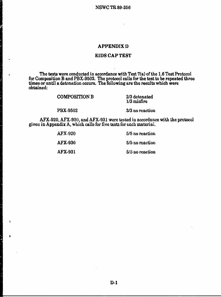
The tests were conducted in accordance with Test 7(a) of the 1.6 Test Protocolfor Composition B and PBX-9502. The protocol calls for the test to be repeated threetimes or until a detonation occurs. The following are the results which wereobtained:
COMPOSITION B 2/3 detonated1/3 misfire
PBX-9502 3/3 no reaction
AFX-920, AFX-930, and AFX-931 were tested in accordance with the protocolgiven in Appendix A, which calls for five tests for each material.
AFX-920 5/5 no reaction
AFX-930 5/5 no reaction
AFX-931 5/5 no reaction
D-1

NSWC TR 89-356
APPENDIX E
EIDS GAP TEST
The tests on Composition B and PBX-9502 were conducted in accordance withTest 7(b) of the 1.6 Test Protocol. The protocol calls for the test to be repeated threetimes or until a detonation occurs; the test is to be run at a gap of 70 mli. Thefollowing are the results which were obtained:
COMPOSITION B 3/3 detonated
PBX-9502 3/3 no reaction
Figure E-1 shows an "after" shot for PBX-9502. The Expanded Large Scale Gap Test(ELSGT) tube was not shattered, and the explosive material was recovered.
AFX-920, AFX-930, and AFX-931 were tested under the old protocol iven inAppendix A, Under this protocol, the nominal 50 percent detonation point isdeter Mined. However, the reaction at 70 mm can be inferred from the data takenduring the testing. In essence, in order to pass the 1,6 test protocol, the gap pressurerequired to cause detonation must be greater than approxfmately 35 kilobars tbr theELSGT configv 'ation (POP > 36 kilobars). The data for three materials (AFX-920,AFX-930, and AFX-931) indicate a gap pre.sure of approximately 60 kilobers-wellabove the level required for passing.
E-1

x~m V W . ZAI L1UU&JW
POS-TEST--GAP TUBE AND WITNESS PLAT E
POST -TEST-EXPLOSIVE MATERIAL
FIGURE E-1. EXPANDED LARGE SCALE GAP TEST--PBX-9502
E-2

NSWC TR 89-356
APPENDIX F
SUSAN TEST RESULTS
The SUSAN Test (Test 7(c)(i) of 1.6 Test Protocol) results included in this reportand discussed in this appendix are based on three types of sources: (1) tests conductedin strict accordance with the 1.6 Test Protocol, (2) tests conducted with minorvariations in the 1.6 Test Protocol but judged acceptable by competent nationalauthorities, and (3) archival data, not conducted according to the 1.6 Test Protocol,but whose information has been interpreted and judged acceptable by competentnational authorities.
Table F-I summarizes the types of data used for the various substancesdiscussed in Chapter 3.
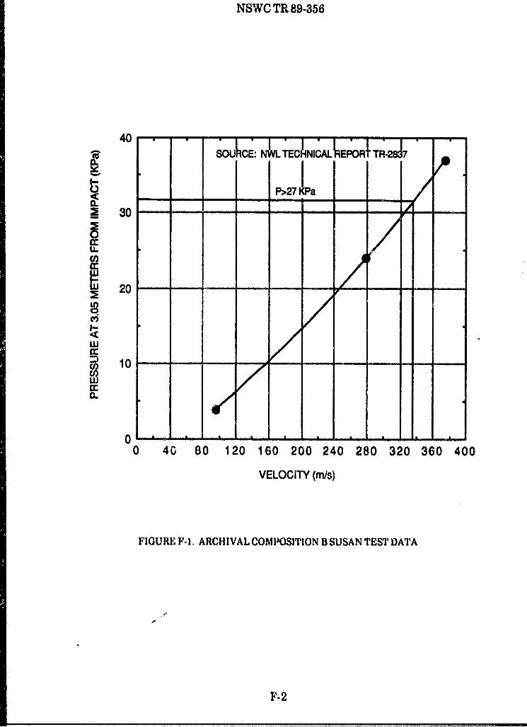
Figure F-1 presents archival data for Composition B. Figure F-2 presentssimilar results for PBX-9502, while Figure F-3 presents results for AFX-920.Table F-2 presents the results obtained for the French sam plea tested under acooperative arrangement with the French government. Table F-3 presentsarchival results for AFX-930 and AFX-931.
It must be remembered that all of the data presented in the tables and figures ofthis appendix have been scaled to sea level conditions; further, the pressures are for arange of 3.05 meters at sea level.
F
-F1i
NSWC TR 89-356
40 •OULE: N•LTECNlCAL6PORtTR*287
I1I
P>27 KPa
S30 - - - --
cc
0 -G -0 -2 -6 20 -4 8 -2 6 0
.
cc
20 O
0 --- 8 1 01 0- 00 4G 0 12 160200 240 280 320 36040
VELOCITY (mis)
FIGUREPI-1. ARCHIVAL COMPOSITION B SUSAN TEST DATA
F- 2

NSWC TR 89-356
10
w
5ww
0
200 250 300 350 400 450 500
VELOCITY (mis)
FIGURE P-2. SUSAN TEST DATA FOR PBX-9502
F-3

NSWC TR 89-356
250 -T--------- T-
25U
w
cc~CL 10
P 27KPa
250 300 350 400 450 500 550 600 650
VELOCITY (ri~s)
IiGURE F-3. SUSAN TEST RESULTS FOR AFX.920

TABLE F-1. TYPES OF SUSAN TEST INFORMATION
SUBSTANCE TEST NUMBER
CO&OSIN B 3
PBX-9502 3
OCTORANE 86A 2
B3003 I
B3103 1
AFX-920 2
AFX-930 2
.TEST MJBER TYPE OF TEST1 'Exact 1.6 Protocol2 Modified 1.6 Protocol judged adequate by competent national authorities3 Archival data Interpreted by competent national authorities
F

NSWC TR 89-356
TABLE F-2. SUSAN TEST RESULTS FOR FRENCH SUBSTANCES
MATERIAL VELOCITY PRESSURE (KPa)_(m/s) Gauge 1 Gaue 2 Gauae 3 Gauce 4
OCTORANE 86A 318 21.9 17.2 31.7 31.6318 19.4 23.7 31.7 22.6318 - 23.7 - 22.0324 21.3 20.0 32.4 22.0324 - 19.1 31.7 21.3
B3003 318 35.2 49.1 55.6 43.2318 37.0 50.1 53.8 41.9324 33.1 48.3 45.8 44.6331 41.3 50.1 54.7 41.2339 38.9 47.3 52.9 41.2346 40.7 49.1 57.3 42.5381 41.4 53.6 58.1 42.5
B3103 318 38.3 51.0 50.3 44.6318 35.9 38.2 48.5 43.2324 41.4 58.9 58.1 46.0331 31.6 47.3 47.6 41.2331 41.4 58.9 58.1 48.0476 41.4 58.9 58.1 52.5
TABLE F-3. AFX.930 AND AFX .931 SUSAN I EST RESULTS
MATERIAL VELOCITY PRESSURE'. ..._ _. .... (m/,s) (KPa)
AFX-930 322 11.5323 11,4321 9.1
AFX-931 266 16.3340 25.8345 26.1
*average of 4 gauges
IF I

NSWC TR 89-356
APPENDIX G
EIDS BULLET IMPACT TEST
The tests were conducted in accordance with Test 7(d)(i) of the 1.6 Test Protocol.The protocol calls for six shots into the test hardware (three from the side and threefrom the eiid) unless a detonation occurs first. The following are the results whichwere obtained:
COMPOSMION B detonated on first impact
PBX-9502 6/6 no reaction
The PBX-9502 specimens were subjected to a deliberate overtest. The protocol callsfor a separate specimen for each shot; that is, each specimen is to be shot from onlyone orientation. Because the PBX-9502 rounds were in such good shape after the firstbullet impact, it was decided to do a second impact on each specimen. Thus eachspecimen was impacted from both the side and the end.
Figures G-1 and G-2 are a sequence of four photographs of PBX-9502undergoing tests. As can be seen, the first bullet impact simply punched a holethrough the material. The second impact split the container, but caused no reaction.
AFX-920, AFX-930, and AFX.931 were also subjected to 1.6 Test Protocol. Thefollowing results were obtained:
AFX-920 6/6 no violent reactions(side impacts burned)(end impacts smoked)
AFX-930 6/6 no violent reactions(both orientations--mild burning)
AFX-931 6/6 no violent reactions(both orientations--endcap ruptures, vigorous burning)
G-1

NA,
0 S0
Ar'vA
G-2

NSWC TR 89-356
7'~
'1 kp
xivS , . zj
000
y t4
G-

NSWC TR 89-356
APPENDIX H
EIDS EXTERNAL FIRE TEST
The tests were conducted in accordance with Test 7(e) of the 1.6 Test Protocol.The protocol calls for either fifteen samples in one fire or five samples in each of threefires. If a detonation occurs on any test, the test may be stopped at that point.
The tests used a liquid fuel (JP-5) fire, as is allowed by the test protocol. Groupsof five samples were utilized in all the tests. One deviation was made from theprotocol. The tests on the PBX-9502 were only performed twice, instead of the threetimes as specified by the protocol. The following are the results which were obtained:
COMPOSITON B 3/5 detonated on first test2/5 no reaction--fell into fire pitAverage Fire Temperature: 843°CTime of Reaction: 239 seconds
PBX-9502 4/5 no reaction--fell into fire pit1/5 expelled end cap < 15 meters
and burnedAverage Fire Temperature: 8030CTime of reaction: 652 seconds
3/5 no reaction--fell into fire pit2/6 deflagrated; pieces expelled
< 15 metersAverage Fire Temperature: 99800Time of Reaction: 982 seconds
Figure H-I is a set of before and after photographs for the first PBX-9502 test.As can be seen, four samples were recovered intact; one had a ruptured end cap.Figures H-2, H-3, and H-4 present the temperature-time profiles recorded within thefires on each test. On the first test of the PBX-9502, the reaction was so nild that onethermocouple continued operating until the flame was extinguished. This can beseen in Figure H-3.
In addition to these test data, data were taken on AFX-920, AFX-930, andAFX-931. This information was taken under the procedures of TB 700-2, which didnot require either multiple test units or multiple tests.
AFX-920 was tested using wood soaked with diesel fuel as the fire source. Thefire reached a temperature of 1080C. Approximately 4 minutes after ignition, anend cap was expelled and the remainder of the test item fell into the fire. A portion ofthe ecplosive filler was ejected approximately 6 meters from its original location.
H-1
NSWC TR 89-356
AFX-930 was tested on a windy day, using wood soaked in kerosene. Because ofthe wind, temperature fluctuations occurred. About 150 seconds after exceeding anair temperature of 5400C, an endcap ruptured, expelling the energetic material 2meters where it burned mildly to completion. The AFX-931 test was performed on awindless day. At 260 seconds after exceeding an air temperature of 540T, the endcapruptured, expelling the energetic material in three pieces. One piece was propelledabout 42 meters where it burned mildly. Another landed about 12 meters away,while the majority of the charge burned mildly to completion about 4 meters from itsoriginal position. Judgement by competent national authority was that thisconstituted a "passing reaction.
H-2

NSWC TR 89-356
im
Ar0
H1-3

NSWC T 89-356
1200 -, .--
1100
1000
3900 b
700 -------
400 --- THERMOCOUPLE I"---0---THERM=CUPLE 4 .
THERMOCOUPLE 6.. .. THERMOCOUPLE 8
200 .HERPLE 12
100 THERMOCOUPLE 12
0 so 100 150.- 200 250TIME (seconds)
V,'GURF H-2. COMPOSIION H
H-4

1200
1100
* 1000
-. 900 6
S800
700
600
w 500
S400 --- THERMOCOUPLE 1
300 *.-THERMOCOUPLE 2- -
-..- THERMOCOUPLE 3
200 - THE RMOCOUPLE 4 --
1000 THERMOCOUPLE 5
100-..C- THERMOCOUPLE 6
0 100 200 300 400 500 600 700 800 900 1000
TIME (seconds)
P~IGURE HI-3. PBX-9602: TEST 1
H-6

NSWC TR 89-356
1200
1 100
900
800 - -- ,t
700 - --
200
500
0 100 200 300 400 500 600 700 800 900 1000
TIME (seconds)
FIGURE HR.4. PBX-902: TEST 2
H-6

NSWC TR 89-356
APPENDIX I
EIDS SLOW COOKOFF TEST
The tests were conducted in accordance with Test 7(0) of the 1.6 Test Protocol.The protocol calls for a sample to be placed into an oven and the temperature raisedat a rate of 3.3C per hour. The test is repeated on three samples. Ifa detonationoccurs on any test, no further tests are required.
Figure I-1 is a set of before and after photographs for the Composition B tests.As can be seen, both samples detonated, destroying the ovens. A different configura-tion of oven was used in the testing of the PBX-9502. These differences have beenshown to not affect the results. Figure 1-2 shows photographs of this type of arrange-ment. Figure 1-3 shows five temperature-time profiles obtained for one of theComposition B samples (note: all of the measuring points were on the surface of thetest specimen). Figures 1-4 to 1-6 show the results obtained for the PBX-9502specimens. The fact that there is little spread in the apparent width of the linesreflects the uniformity of the heating rate.
The following are the results which were obtained:
COMPOSITION B 2/2 detonated
PBX-9502 3/3 no violent reaction
Composition B detonated 26.5 hours after heating began. The reaction in oneoven triggered a reaction in the other. The temperatures at the time of reaction were171.5°C and 170.9°C, respectively. On the three PBX-9502 tests, reactions occurredat the following times and temperatures:
48.00 hours 252.5°C56.75 hours 220.10C43.58 hours 155.10C.
In each of these cases, the reaction was a mild pressure rupture, with little or nodamage to the oven.
In addition to these, test data, archival information was available on AFX-920,AFX-930, and AFX-931.
AFX-920 3/3 mild pressure burst(temperature of approximately 160C on each test)
1-1

NSWC TR 89-356
AFX-930 2/2 mild pressure burst--endcaps expelled about2 meters-burned to completion
(temperature of between 180°C to 190°C on each test)
AFX-931 2/3 mild reaction--endcaps expelled short distance--burned to completion
1/3 deflagration--endcaps ejected; end of pipe belledduring the pressure rupture
(temperature between 17OC and 1800C on each test)
1-2

NSWC TR 89-356
PRE-TET
POSr-Tw~
FIGURE 1-1. IEIDS SLOW COOKOFF ThS: COMPOSITION B
1-3

t*
EIXTERNAL VIEW OF OVEN
TESTSAMPLE'WJITHIN OVENPIGUREJ -2. BIDS SLOW CoOKO~q4 '$'S? PBX..962
1.4

NSWC TR 89-356
I I V 9 9 1 1 1 1 1 1 I I I
cJ
000
0 0
__O 00l
0 If) 0 If)dl3.

NSWC TR 89-356
-\ ~jI- V--
(0o) H(UVWdVQ0
0)-

NSWC TH 89-66
C#)
040
_ __iw
0 0D 0 0L0
(Oo) 3HfIIVtUdV413i
1.7

f- -
4"
:3
-4- C)%. 0l V
(o) D _________N
DISTRIBUTION
Copies Copies
Defense Technical Information Chief of Naval ResearchCenter Attn: ONR-410 1
Cameron Station ONR-430 1Alexandria, VA 22304-6145 12 800 N. Quincy Street
Arlington, VA 22217Library of CongressAttn: Gift and Exchange Division Office of Naval TcehnologyWashington, DC 20540 4 Attn: ONT-232 1
800 N. Quincy StreetChairman Arlington, VA 22217Department of Defense Explosives
Safety Board Chiefof Naval OperationsAttn: DDESB-KT 50 Attn: OP-411F 1
DDESB-KT1 (J. Ward) 1 Department of the Navy2461 Eisenhower Avenue Washington, DC 20350Alexandria, VA 22331-0600 ConmmanderOffice of the Secretary of Defense Naval Sea Systems CommandODDRE (R&AT/ET) Attn: SEA-0333 1Attn: R. Menz 1 SEA-665 3Washington, DC 20301-3080 SEA-66511 I
SEA-662 1Office of the Secretary of Defense SEA-996 12 1OUSDRE (OM) Naval Sea Systems CommandWashington, DC 20301-3080 1 Headquarters
Washington, DC 20362-5101Defense Logistics AgencyAttn: K. Siler 1 Commander805 Walker Street Naval Air Systems CommandMarietta, GA 20050 Attn: AIR-516C 1
Library 1Commander Washington, DC 20361Military Traffic Management
Command Commanding OfficerAttn: MT-SS 1 Naval Facilities Engineering5611 Columbia Pike CommandFalls Church, VA 22041-5050 Attn: Code 03 1
Code 032E 1Director Code 04A4 1Defense Nuclear Agency Code 04T5 IAttn: Code LEEE (J .Eddy) 1 200 Stovall Street6801 Telegraph Road Alexandria, VA 22332Alexandria, VA 23310-3398
(1)

NSWC TR 89-356
DISTRIBUTION (Cont.)
copies Copies
Commander CommanderNaval Civil Engineering Laboratory Naval Safety CenterAttn: Code L51 1 Attn: Code 43 1
Code L51 (Tancreto) 1 Naval Air StationPort Hueneme, CA 93043 Norfolk, VA 23511
Commanding Officer HeadquartersNaval Research Laboratory Department of the ArmyAttn: Technical Information Attn: DALO-SMA
Section 1 Room ID567, PentagonWashington, DC 20375 Washington, DC 20310-0541
Commanding Officer HeadquartersNaval Weapons Center Department of the ArmyAvttr: Code 38 1 Attn: DACS-SF (R. Fatz)
Code 62 1 Room 2C717, PentagonCode 3208 1 Washington, DC 20310-0541Code 321 1Code 3212 1 CommanderCode 326 1 Armament Research, DevelopmentCode 3269 1 and Engineering CenterCode 3276 1 U.S. Army Armament, MunitionsCode 6212A 1 and Chemical CommandLibrary 1 Attn: AMCPM-AL
China Lake, CA 93555 (D. Scarborough) ISMCAR-AEE-BR
Commander (W. Seals) 1David Taylor Research Center SMCAR-AESAttn: Code 1740 1 (S. Kaplowitz) 1
Library i Picatinny Arsenal, NJ 07806-5000Bethesda, MD 20084
CommanderCommanding Officer U.S. Army Materiel CommandNaval Explosive Ordnance Attn: AMCAM-LCP (G. Bottjer) I
Disposal Technology Center AMC-SF-E (R. Vaselitch) 1Attn: Technical Library 1 5001 Eisenhower AvenueIndian Head. MD 20640-5000 Alexandria, VA 22333-0001
Commanding Officer CommanderNaval Ordnance Station USA Safety CenterAttn: Code 04 (M. Hudrn) 1 Attn: CSSCI-PR
Technical Library 1 Ft. Rucker, AL 36362-5363Indian Head, MD 20640
DirectorCommanding Officer AMC Field Safety ActivityNaval Weapons Support Center Attn: AMXOS-SEAttn: Code 50 1 Charlestown, IN 47111-9669Crane, IN 47522-5083
(2)

DISTRIBUTION (Cont.)
Copies Copies
Director CommanderU.S. Army Technical Center for USA Construction Engineering
Explosives Safety Research LaboratoryAttn: SMCAC-ES 1 P.O. Box 4005
SMCAC-ESL 1 Champaign, IL 61820 1Savanna, IL 61074-9639
Commanding GeneralDirector A.S. Arm Missile CommandU.S. Army Defense Ammunition Attn: AMSMIRD-PR-T (Thorn)
Center and School Redstone Aisena), AL 35898Attn: J. Byrd 1Savanna, IL 61074-9639 AFISC/SEWV
Attn: P. r rice 1Executive Director for LTCOL J. Humphr-y 1
Explosives Safety W. Blount 1Attn: AMCDRM I E. Smith 15001 Alexandria, VA 22333-5000 Norton AFB, CA 92049-7001
Director AFSG/IGFWUS Army Engineer Waterways Attn: W. Hammer
Experiment Station Andrews AFBAttn: K. Davis 1 Washington, DC 20334
C. Joachim 1CEWES (J. Ingram) 1 AFLC/IGFW
P.O. Box 631 Attn: W. Rieder 1Vicksburg, MS 39180 Wright Patterson AFB,
OH 45433-5001ComnmanderUS Army Ballistics Research OO-ALC/MMWE
Laboratory Attn: MAJ C. Dougherty IAttn: SLCBR-TB-3 I G. Stratman 1
SLCBR-TB-EE I Hill AFB, UT 84056AMXBR-TBD 1
Aberdeen Proving Ground, Air Force Arnament LaboratoryMD 21005-5066 Attn, MSD/XRS (J. Jenus) 1
MSD/XRS (K Gravois) 1Commander MSD/SE (Collins) 1US Army Toxic & Hazardous MNE (arsons) 1
Materials Agency MSD/SES (F. West) IAttn: DRXT1i-TE 1 Eglin AFIB, FL 32542-5434Aberdeen Proving Ground,
MD 21010 ConuanderAir Force Weapons Laboratory
Commanding General Attn: NTE 1US Army Natick Research and NTESS 1
Development Conuand Kirtland Air Force BaseAttn: Library 1 Albuquerque, NM 87117-6008Natick, MA 01782
(3)

DISTRIBUTION (Cont.)
Copies Copies
Air Force Astronautics Laboratory Mortou ThiokolAttn: R. Weiss 1 Attn: W. Thomas
C. Merrill 1 P.O. Box 400006F. Roberto I Huntsville, AL 35815-1506
Edwards AFB, CA 93523Wilfred Baker Engineering
Department of Energy 6700 Crown Hill, Suite 310Quality Verification Division P.O. Box 6477Attn: Code EH-321 San Antonio, TX 78209
(E. Patagalia) 1Washington, DC 20545 Southwest Research Institute
Attn: W. Herrera ILos Alamos National Laboratory P. Bowles IAttn: L. Hantel 1 Technical Library I
Technical Library 1 P.O. Box 28510P.O. Box 1663 6220 Culebra RoadLos Alamos, NM 87545 San Antonio, TX 78284
Lawrence Livermore National TERALaboratory New Mexico Institute of Mining
Attn: M. Finger 1 and TechnologyE. Lee I At.tn: T. JoynerTechnical Library 1 Socorro, NM 87801
Livermore, CA 94550CETR
Mason & Hanrer New Mexico Institute of MiningAttn: A.G. Papp I and TechnologyP.O. Box 30020 Attn: P.A. PerswonAmarillo, TX 79177 Sotorro, NM 87801
Department of the Interior ITr Research InstituteBureau of Mines Attn: Technical LibraryPitteburgh Research Conter 10 West 35th StreetAttn: R. Watson I Chicago. IL 60616Cochrans Mill RoadPittsburgh, PA 15236-0070 Napadensky Engineers, Inc.
Attn: Ms. Hyla NapadeaakyDepartment of Transportation 650 Judson AvenueAttn: DHIM-21 (C. Shultz) I Evanston, IL 60202-2551400 7th Street$SWWashington, DC 20590 Advanced Technology, Inc.
Attn: W. SmithInstitute of Makers of Explosives L. Wilson1120 19th Street NW, #310 2121 Crystal DriveWashington, DC 20036-3605 1 Arlington, VA 22202
NSACSSAttn: G74(TA)Ft. George G. Meade,
MD 20755-6000
14)

NSWC TR 89-356
DISTRIBUTION (Cont.)
Copies Copies
Kilkeary, Scott & Associates, Inc. Internal Distribution:Attn: F. McCleskey 1 E231 2
G. Clatterbuck 1 E232 32009 N. 14th Street, Suite 408 H12 1Arlington, VA 22201 R 1
R04 (C. Dickinson) 1Applied Ordnance Technology RI0 1Attn: R. Beauregard 1 R10B 1
E. Daugherty 1 R10C 12001 Jefferson Davis Highway, R10F 1
Suite 909 R101 1Arlington, VA 22209 R11 1
R11 (J. Leahy) 1Applied Ordnance Technology R11 (C. Gotzmer) 1Attn: Pilot NiMIC 1 R1 (R. Doherty) 11000 Century Plaza, Box 24, R12 1
Suite 212 R12 (B. Baudler) 110630 Little Patuxent Parkway R13 1Columbia, MD 21044 R13 (D. Tasker) 1
R13 (R. Baker) 1Vitro R13 (D. Price) 1Attn: W. Price 1 R13 (J. Forbes) 1400 Virginia Ave., SW, Suite 825 R14 1Washington, DC 20024 R15 1
R15 (M. Swisdak) 10JHU-APL/CPIA R15 (P. Montanaro) 1Attn: T. Christian 1 RI5 (V. Moore) 1Johns Hopkins Road R15 (J. Connor) 1Laurel, MD 20707 R15 (D. Crabtree) 1
R15 (J. Powell) 1Atlantic Research Corporation R16 1Attn: K. Graham (Bldg. 233) 1 U32 15945 Wellington RoadGainesville, VA 22055-1699
Aerojet Solid PropulsionP.O. Box 15699CSacramento, CA 95852-1699 1
Integrated Systems Analysts, Inc.Attn: K. Shopher 1740 Bay Blvd.Chula Vista, CA 92010
Integrated Systems Analysts, Inc.Attn: E. Jacols 17 Buckingham WayShalimar, FL 32579
(5)

REPORT DOCUMENTATION PAGE j OB%04_0188
Public reporting burden for this collection of information Is estimated 10 average I hour per response, including the time for reviewing Instructions, searching existing datasources, gathering and maintaining the data needed, and completing and reviewing the collection of information. Send conmments regarding this burden estimate or any otheraspect of this collection of Information, Including suggestions for reducing this burden, to Washington Headquarters Services, Directorate for Information Operations andReports, 12 15 Jefferson Davis Highway. Suite 1204, Arlington, VA 22202-4302, anid to the Office of Management and Budget, Paperwork Reduction Project (0704-0188)Washington. DC 20503.
1. AGENCY USE ONLY (Leave blank) 2. REPORT DATE 3. REPORT TYPE AND DATES COVERED
1 December 198914. TITLE AND SUBTITLE S. FUNDING NUMbERSHazard Class/Division 1.6: Articles Containing ExtremelyInsensitive Detonating Substances (EIDS) PE - 65805A
6. AUTHOR(S)
Michael M. Swisdak, Jr.
* 7. PERFORMING ORGANIZATION NAME(S) AND ADDRESS(ES) 8. PERFORMING ORGANIZATIONREPORT NUMBER
Naval Surfatce Warfare Center (1115)10901 New Hampshire Avenue NSWC TR 89-356Silver Spring, MD 20903-5000
9. SPONSORINGIMONITORING AGENCY NAME(S) AND ADDRESS(ES) 10. SPONSORINGNIM NITORINGAGENCY REP ORT NUMBER
Department of Defense Explosives Safety Board2461 Eisenhower AvenueAlexandria, VA 223'al-0600
12s. DISTRIBUTIONAVAILABILITY STATEMENT 12b. DISTRIBUTION CODE~
Approved for public release; distribution is unlimited
13. ABSTRACT (Maximum 200 words)
A brief history of Class/Division 1.5/1.6 is presented. The protocol which has been developed andapproved by the United Nations for testing these materials is givo3n and discussed. The results of testingto determine if certain substances are Extremely Insensitive Detonating Substances (EIDS) is presented.The calibration of the Expanded Large Scale Gap Test (ELSOT), one of the tests for an EIDS, is alsopresented.
14. SUBJECTTERMS 5S. NUMBER OF PAGESHazard Cl1assification Testing AF"X-920 85Hazard Class 1.5 PBX-9502 AFX-930 16. PRICE CODEhazard Class 1.6 Composition B AFX-931
17. SECURITY CLASSIICATION 18I. SECURITY CLAS~C:ATION Ill9, SECURITY CLASSIFICATION 20. LIMnIATION OfOlFREPORT OF THIS PAGE OF ABSTRACT ABSTRACT
UNCLASSIFIED IUNCLASSIFLO) UNCLASSIFIED SARRN 757U -20 XJO~O Standard Form 290 (Rev. 2U
Prescribed by ANSI Std. Z39- 19

GENERAL INSTRUC7IONS FOR COMPLETING SF 298
The Report Documentation Pape (RDP) is used in announcing and cataloging reports. It is imortant thatthis information be consistent with the rest of the report, particularly the cover and its' title page.Instructions fnr fillinq in each block of the form follow. It is important to stay within the lines to meetoptical scanning requirements.
Block 1. Agency Use Only (Leave blank). Block 12a. Distribution/Availability Statement.Denotes public availability or limitations. Cite any
Block 2. Report Date. Full publication date including availability to the public. Enter additionalday, month, and year, if available (e.g. 1 Jan 88). limitations or special markings in all capitals (e.g.Must cite at least the year. NOFORN, REL, ITAR).
Block 3. Type of Report and Dates Covered. Statewhether report is interim, final, etc. If applicable, DOD - See DoDD 5230.24, "Distributionenter inclusive report dates (e.g. 10 Jun 87 - Statements on Technical Documents."30 Jun 88). DOE - See authorities.
Block 4. Title and Subtitle. A title is taken from the NASA - See Handbook NHB 2200.2part of the report that provides the most meaningful NTIS - Leave blank.and complete information. When a report is pre-pared in more than one volume, repeat the primarytitle, add volume number, and include subtitle for Block 12b. Distribution Code.the specific volume. On cissified documents enterthe title classification in parentheses. DOD - Leave blank.
DOE - Enter DOE distribution categoriesBlock 5. Funding Numbers. To include contract and from the Standard Distribution forgrant numbers; may include program element Unclassified Scientific and Technicalnumber(s), project number(s), task number(s), and Reports.work unit number(s) Use the following labels: NASA - Leave blank.
NTIS - Leave blank.C - Contract PR - Project
- Grant TA - Task Block 13. Abstract. Include a brief (Maximum 200PE - Program WU - Work Unit words) factual summary of the most significant
Element Accession No. information contained in the report.
BLOCK 6. Author(s). Name(s) of person(s)responsible for writing the report, performing the Block 14. Subiect Terms. Keywords or phrasesresearch, or credited with the content of the report. identifying major subjects in the report.If editor or compiler, this should follow the name(s).
Block 1 5. Number of Pages. Enter the totalBlock 7. Performino Organization Name(s) and number of pages.Address(es). Self-explanatory.
Block 16. Price Code. Enter appropriate price codeBlock 8. Performingl Organization Report Number. (AllIS ol)
Enter the unique alphanumeric report number(s)
assigned by the orgakiization performing the report. Blocks 17.-19. Security Classifications. Self-
Block 9. Soonsoring/Monitorinq Agencv Name(s explanatory. Enter U.S. Security Classification inand Address(es). Self-explanatory. accordance with U.S. Security Regulations (i.e.,
UNCLASSIFIED). If form contains classifiedBlock 10. Sponsoring/Monitoring Agencv Report information, stamp classification on the top andNumber. (If Known) bottom of the page.
Block 11. Supplementarv Notes. Enter information Block 20. Limitation of Abstract. This block mustnot included elsewhere such as: Prepared in coop- be completed to assign a limitation to the abstract.eration with...; Trans. of...; To be published in.... Enter either UL (unlimited) or SAR (same as report).When e, report is revised, include a statement An entry in this block is necessary if the abstract iswhether the new report supersedes or supplements to be limited. If bank, the abstract is assumed tothe older report. be unlimited.
Standard Form 298 Back (Rev. 2-89)