N-1000-III/IV Installation and Programming Manual
121
N-1000-III/IV Installation and Programming Manual TD1064 rev0400 - NCI ADEMCO Part # K4788
Transcript of N-1000-III/IV Installation and Programming Manual

N-1000-III/IVInstallation andProgramming
Manual
TD1064 rev0400 - NCIADEMCO Part # K4788

i i i i iN-1000-III/IV
Notices
Fire Safety Notice: Never connect any card reader devices or locks to door, gates or barrierswithout first consulting the local fire codes. You must consult with and get approval of, local fireofficials before installing locks or devices on any doors that may be fire exits. Use of egress pushbuttons may not be legal. Single action exit may be required. Always obtain proper permits andapprovals in writing before installing equipment.
Notice: This equipment has been tested and found to comply with the limits for a Class A digitaldevice, pursuant to part 15 of the FCC Rules. These limits are designed to provide reasonableprotection against harmful interference when the equipment is operated in a commercial environ-ment. This equipment generates, uses, and can radiate radio frequency energy and, if not installedand used in accordance with the instruction manual, may cause harmful interference to radiocommunications. Operation of this equipment in a residential area is likely to cause harmfulinterference in which case the user will be required to correct the interference at his own expense.
Notice: The information in this document is subject to change without notice.
Notice: This document and the data herein shall not be duplicated, used or disclosed to others forprocurement or manufacturing, except as authorized with the written permission of NorthernComputers, Inc. The information contained within this document or within the product itself isconsidered the exclusive property and trade secrets of Northern Computers, Inc. All information inthis document or within the software product itself is protected by the copyright laws of the UnitedStates.
Notice: Any use of this product is subject to the terms and acceptance of the Northern Computers,Inc. “Software Agreement.” Please request a copy from Northern Computers, Inc. and review thisagreement carefully.
IBM is a trademark and/or a registered trademark of Internationl Business Machines Corporation.MS-DOS, Windows, Windows NT, Windows ’95, Windows ‘98 are trademarks and/or registeredtrademarks of Microsoft Corporation in the United States and/or other countries. The use of Cotag,Wiegand, IDI, Continental, NCS, Dorado, Indala, Motorola & Hayes may or may not be registeredtrademarks/technologies of those respective companies.
© 2000 Northern Computers, Inc. All rights reserved.

i ii ii ii ii i N-1000-III/IV

iii iii iii iii iiiN-1000-III/IV
ContentsContentsContentsContentsContents
UL Note............................................................................................................. viNew and Improved Features of the N-1000-III/IV ............................................. vii
Section 1: Introduction/Access Control ............................................................. 1-1
Section 2: System Overview ............................................................................ 2-12-1: N-1000-III/IV ........................................................................................................................................... 2-12-2: Programming Devices ............................................................................................................................... 2-22-3: C-100-A1 Converter ................................................................................................................................... 2-42-4: N-485-PCI-2 or HUB-2 .............................................................................................................................. 2-42-5: PROM Versions .......................................................................................................................................... 2-4
Section 3: Hardware Specifications .................................................................. 3-1
Section 4: Installation/Panel Layout ................................................................. 4-14-1: Four Reader Board (N-1000-IV only) ........................................................................................................... 4-24-2: Terminal Blocks 1, 2, 3, 4 .......................................................................................................................... 4-44-3: Terminal Block 5 ....................................................................................................................................... 4-64-4: Terminal Block 6 ....................................................................................................................................... 4-64-5: Terminal Block 7 ....................................................................................................................................... 4-84-6: Terminal Block 8 ......................................................................................................................................4-104-7: Terminal Block 9 ......................................................................................................................................4-104-8: DIP Switch Settings ..................................................................................................................................4-124-9: Jumpers ..................................................................................................................................................4-144-10: Connectors ............................................................................................................................................. 4-154-11: LEDs .....................................................................................................................................................4-164-12: Restart Button ........................................................................................................................................4-184-13: RAM Chip ..............................................................................................................................................4-184-14: PROM Chip ............................................................................................................................................4-184-15: Additional Installation Information .......................................................................................................... 4-18
Section 5: Operation ....................................................................................... 5-15-1: Card Reader/Keypad Operation .................................................................................................................. 5-15-2: Alarm Input Points .................................................................................................................................... 5-45-3: Relay Output Points ................................................................................................................................... 5-55-4: Default Input Point/Output Point Interaction ................................................................................................ 5-65-5: Auto-Relock Operation ..............................................................................................................................5-145-6: Time Zone-Controlled Doors .......................................................................................................................5-14
Section 6: Wiring Requirements ....................................................................... 6-16-1: Card Readers ............................................................................................................................................ 6-16-2: Four Reader Board (N-1000-IV Only) .......................................................................................................... 6-36-3: Eleven Conductor Keypads ......................................................................................................................... 6-56-4: Alarm Input Points .................................................................................................................................... 6-76-5: Relay Output Points ................................................................................................................................... 6-7
i vi vi vi vi v N-1000-III/IV
6-6: Communications ....................................................................................................................................... 6-76-6-1: PC to C-100-A1 .............................................................................................................................. 6-76-6-2: C-100-A1 to Panel(s) ...................................................................................................................... 6-76-6-3: AEP-3 to N-1000-III/IV ................................................................................................................... 6-86-6-4: PC to N-485-PCI-2 ....................................................................................................... .................. 6-126-6-5: N-485-PCI-2 to Panel .................................................................................................................... 6-126-6-6: N-485-HUB-2 to Panel .................................................................................................... .............. 6-136-6-7: N-485-HUB-2 to Modem ................................................................................................................ 6-136-6-8: Bias and EOL with 485 Communication .......................................................................................... 6-14
6-7: Cable Specifications ................................................................................................................................. 6-186-8: NCI Cable Part Numbers ............................................................................................................................ 6-196-9: Configurations for RS-232 Serial Communication Ports ................................................................................. 6-20
Section 7: Locks and Suppression .................................................................... 7-1
Section 8: Grounding ...................................................................................... 8-1
Section 9: Power ............................................................................................. 9-1
Appendix A: Programming Quick Reference Guide ..........................................A-1Commands ...................................................................................................................................................... A-5
A Command ............................................................................................................................................ A-5C Command ............................................................................................................................................. A-6D Command ............................................................................................................................................ A-8E Command ............................................................................................................................................ A-9F Command ............................................................................................................................................ A-10G Command ........................................................................................................................................... A-12H Command ........................................................................................................................................... A-13I Command ............................................................................................................................................ A-13L Command ............................................................................................................................................ A-14M Command ........................................................................................................................................... A-15N Command ........................................................................................................................................... A-16O Command ........................................................................................................................................... A-17P Command ........................................................................................................................................... A-18R Command ........................................................................................................................................... A-18T Command ............................................................................................................................................ A-19V Command ........................................................................................................................................... A-19W Command (Used with the N-1000-III/IV only) ........................................................................................ A-20Z Command ............................................................................................................................................ A-21
OR’ing of Inputs ............................................................................................................................................. A-21Output Groups by Readers ....................................................................................................... ......................... A-22
Appendix B: N-1000-III/IV Compared to N-1000-II......................................... B-1
Appendix C: Troubleshooting ...........................................................................C-1N1000-III/IV Self-Test Capability ........................................................................................................................ C-3
Index ..............................................................................................................C-1
v v v v vN-1000-III/IV
Preface
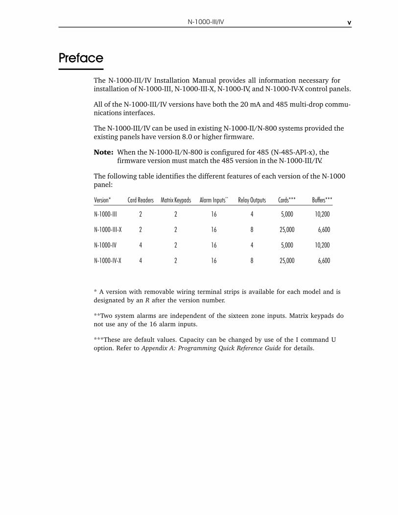
The N-1000-III/IV Installation Manual provides all information necessary forinstallation of N-1000-III, N-1000-III-X, N-1000-IV, and N-1000-IV-X control panels.
All of the N-1000-III/IV versions have both the 20 mA and 485 multi-drop commu-nications interfaces.
The N-1000-III/IV can be used in existing N-1000-II/N-800 systems provided theexisting panels have version 8.0 or higher firmware.
Note: When the N-1000-II/N-800 is configured for 485 (N-485-API-x), thefirmware version must match the 485 version in the N-1000-III/IV.
The following table identifies the different features of each version of the N-1000panel:
Version* Card Readers Matrix Keypads Alarm Inputs** Relay Outputs Cards*** Buffers***
N-1000-III 2 2 16 4 5,000 10,200
N-1000-III-X 2 2 16 8 25,000 6,600
N-1000-IV 4 2 16 4 5,000 10,200
N-1000-IV-X 4 2 16 8 25,000 6,600
* A version with removable wiring terminal strips is available for each model and isdesignated by an R after the version number.
**Two system alarms are independent of the sixteen zone inputs. Matrix keypads donot use any of the 16 alarm inputs.
***These are default values. Capacity can be changed by use of the I command Uoption. Refer to Appendix A: Programming Quick Reference Guide for details.

v iv iv iv iv i N-1000-III/IV
UL Note
The N-1000-III/IV panel’s alarm point monitoring only monitors the door position(UL294). It is not intended as a proprietary burglar alarm (UL1094).
The control panel was UL294 tested as a stand alone unit only.
The N-485-HUB-2 was not investigated by UL.
The N-1000-III/IV was UL294 tested using the following card readers:
• Model 30387 (CR-1) Wiegand swipe reader.
• Model 5365BGP00 (PR-MINI-PROX) proximity reader.
• Model 5355AGN00 (PR-P-PRO) proximity reader.
The N-1000-III/IV was UL294 tested using the Basler Electric transformer partnumber BE11625CAA-0042 (X-4).

vii vii vii vii viiN-1000-III/IV
New and Improved Features of the N-1000-III/IV
The N-1000-III/IV series panels have both a number of improvements and someunique features as compared to the N-1000-II control panels. Some of thesefeatures are highlighted below. For a more detailed description refer to Appendix Bof this manual.
• Four layer PWB and other improvements provide greater electrical noise immu-nity.
• High efficiency switching regulators result in reduced heat generation andextended backup battery operation.
• A Four Reader Board allows the N-1000-IV panel to support a total of fourreaders. (See Section 4-3 for details.) When this board is present all fourreaders attach to it via its removable terminal strips. A Reader FunctionTest is available on the Four Reader Board by shorting a pair of jumper prongslabeled TEST. This will cause the board to generate a simulated card read fromeach of the four readers.
• An improved canister has more knockouts, a larger battery bracket and im-proved wiring space, since the board is centered in the enclosure. (The oldenclosure can be field retrofitted for the new board.)
• The processor speed is substantially faster than the standard N-1000-II, increas-ing the speed of internal processing. At the same time, communications outputis the same as the N-1000-II panels so they can be used in the same loop.
• An additional Terminal Block (TB9) has been added in the upper left quadrantof the board. This terminal block has an Earth Ground connection; a batteryplus and minus (in addition to the soldered-in battery wires); AC connections 1and 2 (there are no spade lugs for AC or battery); the Tamper and ExternalPower Status inputs with common posts; and a place to tie the RS-485 shields.
• The N-1000-III/IV firmware (version 08.01.29 or later) has a built-in testcapability that can be used to check the functioning of most of the circuitboard’s hardware. This feature is detailed in Appendix C: Trouble Shooting.
• There are both RS-485 and RS-232 communications ports in addition to the 20milliamp port. The RS-485 port is selected by a change of Jumper 1 in lieu ofthe 20 milliamp. The RS-232 port can be used in addition to or instead of theother ports.
• A 16.5 volt AC power source is now required, allowing the charging of a 12 voltbattery for back-up as well as the supply of 12 volt reader and PIR egress powerfrom the N-1000-III/IV.
• A 12 volt, 500 mA output is available for powering 12 volt readers or PIRegress detectors. Connections for this are at TB9 terminals 7 (+) and8 (Common).

vi i iv i i iv i i iv i i iv i i i N-1000-III/IV
• Detection of a primary power failure by either the internal sensor or theinput from the relay on the external supply will generate an Alarm 19 notAlarm 8. Alarm Point 8 is now available for use as a standard alarm point
• Automatically resetting solid state fuses are used.
• The Green Low-V OK LED will go off to indicate low 12 Volt battery (indicatorturns off at approximately 10.1 volts, the panel shuts down at approximately9.9 volts) or disconnected RAM back-up (JP9 removed).
• A special set of connectors for the AEP-3 Relay Expansion board is provided. J1is a connector for the present AEP-3 Board design. J2 is a double connector andwill be used for a future development.
• There are screw terminals for the reader cable shield connections. These arenearer to where the wires come in, eliminating the need to run the shield wirearound the board.
• The terminals on Terminal Block 8 are used exclusively for 11 wire Keypads.This makes all regular inputs available even when a keypad is used. The Koption is no longer needed. The P option must still be entered for use withPINs. Screw Terminal 4 is used for the Black (Ground) wire of the Keypad.
• There is a separate Tamper Input located on TB9. This makes Input 12 (termi-nal now located on TB6) available as a regular alarm input.
• Each input can be individually programmed for both Normally Open or NormallyClosed and Supervised or Non-Supervised operation.
• There are several changes to the System inputs.
Alarm 17 Communications status alarm, but now it reports for either 20 mAor 485 failures.
Alarm 18 Reserved for future reporting of an Auxiliary Communications Status(the RS-232 port.)
Alarm 19 Primary Power Fail alarm.
Alarm 20 Tamper alarm (with special terminal connections on TerminalBlock 9).
Alarm 21 Input Ground Fault alarm. If the input is shorted to Earth Groundthis alarm will be generated. (Some fault conditions may generatean ALARM rather than TROUBLE from the point, but no ground faultwill be interpreted as NORMAL.)
Alarm 22 Reserved for future use.
Alarm 23 Indicates an external 5 volt reader power short circuit.
Alarm 99 Generated at restart either due to the Push Button or the watch dogtimer. (This alarm cannot be stored in the history buffer.) A 99trouble is communicated on a cold boot-up reset when the RAMmemory is being initialized.
• Relays are heavy duty inductive load rated. They have a maximum load ratingof 30 VDC, 5 A Resistive, 2 A Inductive. They also have circuitry which is lesssusceptible to electrical switching noise.

Section 1: Access ControlSection 1: Access ControlSection 1: Access ControlSection 1: Access ControlSection 1: Access Control N-1000-III/IV 1–1
INTRODUCTION
Section 1: Access Control
Access control is computerized control over entry to any area that can be securedwith a lock and key. Entry is only allowed to authorized people at authorized times.Control of who is allowed to come and go is easily maintained.
The weakness of a lock and key security system is the common key. The key is areadily duplicated piece of metal that gives anyone who holds it access to an area.The risk of lost or stolen keys, with the expense of changing locks, is a costlyproblem. Access control is an effective and affordable solution to this problem.With access control, each person receives a card or keycode which restricts accessto authorized areas at authorized times. A small, programmable control panelallows or denies access. If a card is lost or stolen, or if a keycode is no longersecure, the control panel can be reprogrammed quickly and easily.
An additional benefit of access control is report capability. The system providesreports of all card/keycode activity, including whether access was granted ordenied, and why. A permanent record of all entries to an area can be maintained.

1–2 N-1000-III/IV Section 1: Access ControlSection 1: Access ControlSection 1: Access ControlSection 1: Access ControlSection 1: Access Control
Section 2: System OverviewSection 2: System OverviewSection 2: System OverviewSection 2: System OverviewSection 2: System Overview 2–1 2–1 2–1 2–1 2–1N-1000-III/IVN-1000-III/IVN-1000-III/IVN-1000-III/IVN-1000-III/IV
Section 2: System Overview
2-1: N-1000-III/IV
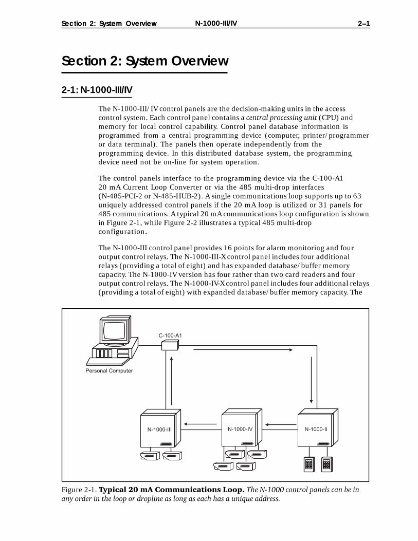
The N-1000-III/IV control panels are the decision-making units in the accesscontrol system. Each control panel contains a central processing unit (CPU) andmemory for local control capability. Control panel database information isprogrammed from a central programming device (computer, printer/programmeror data terminal). The panels then operate independently from theprogramming device. In this distributed database system, the programmingdevice need not be on-line for system operation.
The control panels interface to the programming device via the C-100-A120 mA Current Loop Converter or via the 485 multi-drop interfaces(N-485-PCI-2 or N-485-HUB-2). A single communications loop supports up to 63uniquely addressed control panels if the 20 mA loop is utilized or 31 panels for485 communications. A typical 20 mA communications loop configuration is shownin Figure 2-1, while Figure 2-2 illustrates a typical 485 multi-dropconfiguration.
The N-1000-III control panel provides 16 points for alarm monitoring and fouroutput control relays. The N-1000-III-X control panel includes four additionalrelays (providing a total of eight) and has expanded database/buffer memorycapacity. The N-1000-IV version has four rather than two card readers and fouroutput control relays. The N-1000-IV-X control panel includes four additional relays(providing a total of eight) with expanded database/buffer memory capacity. The
N-1000-IV N-1000-IIN-1000-III
Personal Computer
C-100-A1
-
Figure 2-1. Typical 20 mA Communications Loop. The N-1000 control panels can be inany order in the loop or dropline as long as each has a unique address.

2–22–22–22–22–2 Section 2: System OverviewSection 2: System OverviewSection 2: System OverviewSection 2: System OverviewSection 2: System OverviewN-1000-III/IVN-1000-III/IVN-1000-III/IVN-1000-III/IVN-1000-III/IV
N-1000-III-X is shown in Figure 2-3 with enclosure and battery. Figure 2-4 showsthe N-1000-IV-X with Four Reader Board, battery and enclosure.
The minimum configuration for the N-1000-III/IV includes the control panel,power transformer, reader and communication converter.
Control panels can operate in a buffered mode in which system transactions arestored in transaction buffer memory at the panels rather than transmitted to theprogramming device. Every transaction (input point change of state, code use) usesone location in buffer memory. The buffered information can later be transmittedto the programming device.
The N-1000-III/IV firmware (version 08.01.29 or later) has a built-in test capabilitythat can be used to check the functioning of most of the circuit board’s hardware.Refer to Appendix C: Troubling Shooting for details.
2-2: Programming Devices
N-1000-III/IV control panels in a communications loop are programmed with apersonal computer, printer/programmer or data terminal.
When using a personal computer as the system programming device, the PCsoftware serves as a database manager for the N-1000-III/IV control panels.Information is entered into the PC databases and then downloaded to thecontrol panels. During the download procedure, the PC software converts thedatabase information at the disk level to a series of command strings from theN-1000 instruction set. The commands are then sent to the appropriate controlpanels. The panels then operate independently from the computer. The advan-tages of using a computer as the system programming device include ease ofprogramming and operation, permanent disk storage of all databaseinformation and extensive report options.
Figure 2-2. Typical 485-Multidrop Configuration. The N-1000-III/IV can be used inexisting N-1000-II/N-800 systems provided the existing panels have version 8.0 or higherfirmware. When the N-1000-II/N-800 is configured for 485 (N-485-API-2) as in this example, thefirmware version must match the 485 version in the N-1000-III/IV.
Personal Computer
N485-PCI-2
N-1000-IIN-1000-IV N-1000-III
N-1000-IIwithN-485-API-2

Section 2: System OverviewSection 2: System OverviewSection 2: System OverviewSection 2: System OverviewSection 2: System Overview 2–3 2–3 2–3 2–3 2–3N-1000-III/IVN-1000-III/IVN-1000-III/IVN-1000-III/IVN-1000-III/IV
Figure 2-3. N-1000-III-X Panel with Enclosure. The N-1000-III control panel provides16 alarm points for alarm monitoring capability and four relays for output control capability. TheN-1000-III-X includes four additional relays (providing a total of eight) and has expandeddatabase/buffer memory capacity.
Panel must beearth grounded.
S-4 SUPPRESSIONREQUIRED ACROSSEVERY ACTIVE RELAYAND ELECTRICAL
DEVICE (CONNECTWITHIN 18 INCHES).
Lock Solenoid
1
3456789
10
2
1112
Figure 2-4. N-1000-IV-X Panel with Enclosure. The N-1000-IV supports four card readersand four relays for output control capability. The N-1000-IV-X includes four additional relays withexpanded database/buffer memory capacity.
Panel must beearth grounded.
S-4 SUPPRESSIONREQUIRED ACROSSEVERY ACTIVE RELAYAND ELECTRICAL
DEVICE (CONNECTWITHIN 18 INCHES).
Lock Solenoid
1
3456789
10
2
1112
ShieldGND+5vDØD1LED
ShieldGND+5vDØD1LED
LED D1 DØ +5v GND Shield LED D1 DØ +5v GND Shield
StatusLED Northern Computers, Inc.
Reader 1 Reader 2
Reader 3
Reader 4
To N-1000

2–42–42–42–42–4 Section 2: System OverviewSection 2: System OverviewSection 2: System OverviewSection 2: System OverviewSection 2: System OverviewN-1000-III/IVN-1000-III/IVN-1000-III/IVN-1000-III/IVN-1000-III/IV
When using a printer/programmer or data terminal as the system programmingdevice, all command strings are sent manually to the control panels by the operator.Printer/programmer and data terminal programming provide no safeguardagainst lost database memory at the panel level.
2-3: C-100-A1 Converter
The C-100-A1 Converter serves as the interface between the programmingdevice and the N-1000 control panels. The C-100-A1 allows the programmingdevice, using RS-232 port, to communicate with the control panels in a 20 mAcurrent loop. The C-100-A1 can be configured for use as a C-100-C, C-100-T orC-100-M, determined by the position of six DIP switches on the RS-232connector. These configurations are used as follows:
• computer to local control panels C-100-C• printer/programmer to local control panels C-100-T• computer to remote control panels via modem C-100-M
Refer to the C-100-A1 Manual for further details.
2-4: N-485-PCI-2 or HUB-2
The N-485-PCI-2 is used to interface between a PC’s RS-232 port and the 485multi-drop communications bus. The N-485-HUB-2 is used to interface between amodem’s RS-232 port and the 485 multi-drop bus. Only the “-2” versions of theseproducts will function with the N-1000-III/IV.
2-5: PROM Versions
The N-1000-III/IV PROM (Programmable Read Only Memory) chips providepermanent storage for the program and control logic information necessary tocoordinate and drive the system hardware. The PROM chip is also referred toas the control panel’s FIRMWARE.
The PROM version in use determines the commands and programming featuresavailable for use with the control panel. Operations such as alarm point programming,site code checking, card/ keycode capacity, transaction buffer capacity, Visitorand Limited Use status cards and local anti-passback are all functions of thePROM version in use. Specific command string syntax and the availability ofadvanced programming commands are also dependent upon the PROM version.
Refer to the command summary in Appendix A of this manual. Or contact NCIfor additional information on PROM versions.

N-1000-III/IVN-1000-III/IVN-1000-III/IVN-1000-III/IVN-1000-III/IVSection 3: Hardware SpecificationsSection 3: Hardware SpecificationsSection 3: Hardware SpecificationsSection 3: Hardware SpecificationsSection 3: Hardware Specifications 3–1 3–1 3–1 3–1 3–1
Section 3: Hardware Specifications
Power Requirements:The N-1000-III/IV requires a 16.5 VAC, 50 VA, 60 HZ or 12 VDC linear (2 ampcontinuous) power supply.
Output Power:12 VDC (10 to 14 volts) 500 mA for readers requiring 12 VDC or motion detectordevices (not for use with locking devices). A 5 volt 500 mA output is available forstandard 5 VDC reader requirements.
Battery Backup:The 12 VDC (4 amp/hr.) battery provides up to four hours of full operationalbackup (depending on the load and the age of the battery). To maintain the maxi-mum back-up time, replace the battery every four years or every two years ifoperating at higher temperatures.
Battery Current Draw:Control panel 300 mA 300 mAAlarm points 5 mA each (x 18) 90 mARelays activated 50 mA each (x 8) 400 mA12 V & readers 500 mA maximum 500 mA5 V card readers 500 mA maximum 500 mA
Total 1.8 amps maximum 1.79 amps
Memory Backup:A large value capacitor retains panel memory upon loss of both primary andbackup battery power for up to seven days (depending on ambient temperatureand the number of RAM ICs).
Fuses:3 amp solid-state, non-replaceable, automatic resetting. Depending on theoverload, and the temperature, it may take up to several minutes for the fusesto reset.
Alarm Input Points:Input points are provided which can be configured for either normally open ornormally closed and either 3 state supervised or unsupervised. Separate non-supervisedinputs are provided for an optional external primary power fail indication and thestandard enclosure tamper switch.
Relay Output Points:Four double pole, double throw (DPDT) relay contacts with both normally-openand normally-closed sides, rated for 30 VDC 2 amp inductive loads. The N-1000-III/IV-Xcontrollers provide four additional relays (eight total). These relays can also beutilized in dry circuit applications (e.g. , mechanical shunts, data interruptions,etc.). NOTE: once the relay pole has been used on an inductive load (doorstrikes, magnetic locks, etc.) it cannot be used in low current dry circuit applications.Northern recommends using the “A” pole of the relays for inductive loads andthe “B” pole for dry circuit (logic) loads.

N-1000-III/IVN-1000-III/IVN-1000-III/IVN-1000-III/IVN-1000-III/IV3–23–23–23–23–2 Section 3: Hardware Specifications Section 3: Hardware Specifications Section 3: Hardware Specifications Section 3: Hardware Specifications Section 3: Hardware Specifications
Operating Temperature:35º to 110º F ( 2º to 43º C)
Operating Relative Humidity:Up to 85% non-condensing.
Enclosure:14" H x 16" W x 4" D (35.6 cm x 40.6 cm x 10.2 cm) with knockouts, hinged coverwith lock and key. Enclosure tamper switch provided. The N-1000-III/IV enclosure(with control panel) is illustrated in Figure 3-1.
Weight:21 pounds (9.5 kg) with enclosure and backup battery.
Figure 3-1. Enclosure for the N-1000-III/IV. The N-1000 enclosure, shown here withthe N-1000-IV panel, has a lock and key, knockouts and a tamper switch. A 12 VDC battery ismounted on the door.
Panel must beearth grounded.
S-4 SUPPRESSIONREQUIRED ACROSSEVERY ACTIVE RELAYAND ELECTRICAL
DEVICE (CONNECTWITHIN 18 INCHES).
Lock Solenoid
1
3456789
10
2
1112
ShieldGND+5vDØD1LED
ShieldGND+5vDØD1LED
LED D1 DØ +5v GND Shield LED D1 DØ +5v GND Shield
StatusLED Northern Computers, Inc.
Reader 1 Reader 2
Reader 3
Reader 4
To N-1000

N-1000-III/IVN-1000-III/IVN-1000-III/IVN-1000-III/IVN-1000-III/IVSection 4: PSection 4: PSection 4: PSection 4: PSection 4: Panel Lanel Lanel Lanel Lanel Layoutayoutayoutayoutayout 4–14–14–14–14–1
INSTALLATION
Section 4: Panel Layout
The N-1000-III-X has nine screw-down terminal blocks. Each terminal block, inturn, has 12 individual terminal positions, described in the following sections.Figure 4-1 shows the panel with its printed template. The N-1000-IV-X has anadditional board in place of TB5 (see Figure 4-2) with four removable wiringterminal blocks for connection to four readers. Complete terminal block detailsfollow.
Figure 4-1. N-1000-III Panel. The panel is shown with its printed template.
N-1000-IV FN-1000-IV FN-1000-IV FN-1000-IV FN-1000-IV FourourourourourRRRRReader Boardeader Boardeader Boardeader Boardeader Board

N-1000-III/IVN-1000-III/IVN-1000-III/IVN-1000-III/IVN-1000-III/IV4–24–24–24–24–2 Section 4: PSection 4: PSection 4: PSection 4: PSection 4: Panel Lanel Lanel Lanel Lanel Layoutayoutayoutayoutayout
4-1: Four Reader Board (N-1000-IV only)
The N-1000-IV supports up to four card readers. All four readers attach to thepanel via a special Four Reader Board mounted in the lower right quadrant of theN-1000-IV panel (see Figure 4-2). The wiring terminals are removable andinterchangeable. The regular reader terminals on the main board are not used.This board is connected to the main panel by connector P3, located directlyabove the bottom center of the N-1000 panel.
Typical wire color terminations are illustrated in Figure 4-3. Refer to the readerinstallation technical bulletin (included with the reader) for the most recentcolor terminations.
Figure 4-2. N-1000-IV Panel. The panel is shown with its printed template and the FourReader Board..

N-1000-III/IVN-1000-III/IVN-1000-III/IVN-1000-III/IVN-1000-III/IVSection 4: PSection 4: PSection 4: PSection 4: PSection 4: Panel Lanel Lanel Lanel Lanel Layoutayoutayoutayoutayout 4–34–34–34–34–3
A special, programmable chip, called a PIC chip, controls the Four Reader Board.The PIC chip is labeled with a version number similar to the label on the mainpanel's PROM chips.
The Four Reader Board has its own Status LED that flashes when it is poweredand running. When a card is read the Status LED gives a long flash. When theLED stays on for an extended period of time it indicates that the board has resetdue to an error or power supply problem.
A pair of jumper prongs located on the Four Reader Board allows a readerfunction test. Shorting these prongs (labeled TEST) will cause the board togenerate a simulated card read (with the PIC firmware version ) from each ofthe four readers.
Figure 4-3. Four Reader Board. On the N-1000-IV the Four Reader Board replacesTerminal Block 5 and provides connections for up to four readers.
LED Brown(Aux. Output #14)
Data 1 White
Data Ø Green
+ 5 VDC Red
Ground Black
Shield Cable Drain Wire
Typical reader connections.Refer to reader documentationfor the most recentcolor terminations.
ShieldGND+5vDØD1LED
ShieldGND+5vDØD1LED
LED D1 DØ +5v GND Shield LED D1 DØ +5v GND Shield
StatusLED Northern Computers, Inc.
Reader 1 Reader 2
Reader 3
Reader 4
To N-1000
Aux. Output #13
Aux. Output #12Aux. Output #11
N-1000-III/IVN-1000-III/IVN-1000-III/IVN-1000-III/IVN-1000-III/IV4–44–44–44–44–4 Section 4: PSection 4: PSection 4: PSection 4: PSection 4: Panel Lanel Lanel Lanel Lanel Layoutayoutayoutayoutayout
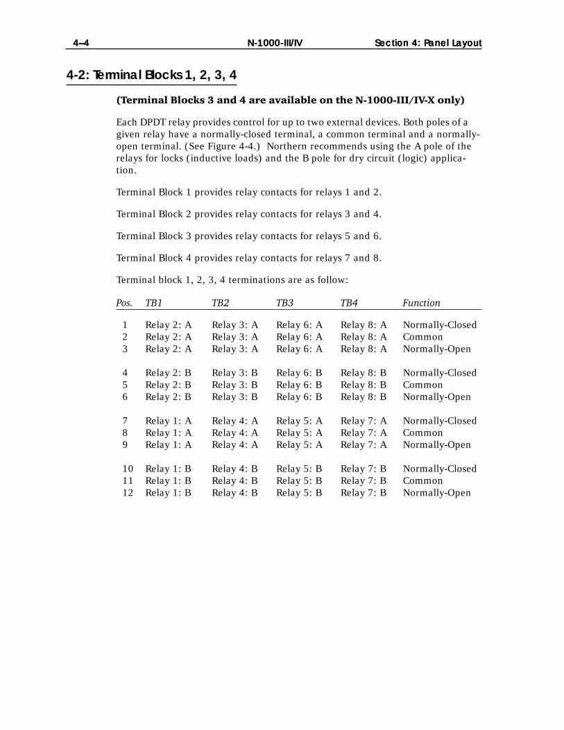
4-2: Terminal Blocks 1, 2, 3, 4
(Terminal Blocks 3 and 4 are available on the N-1000-III/IV-X only)
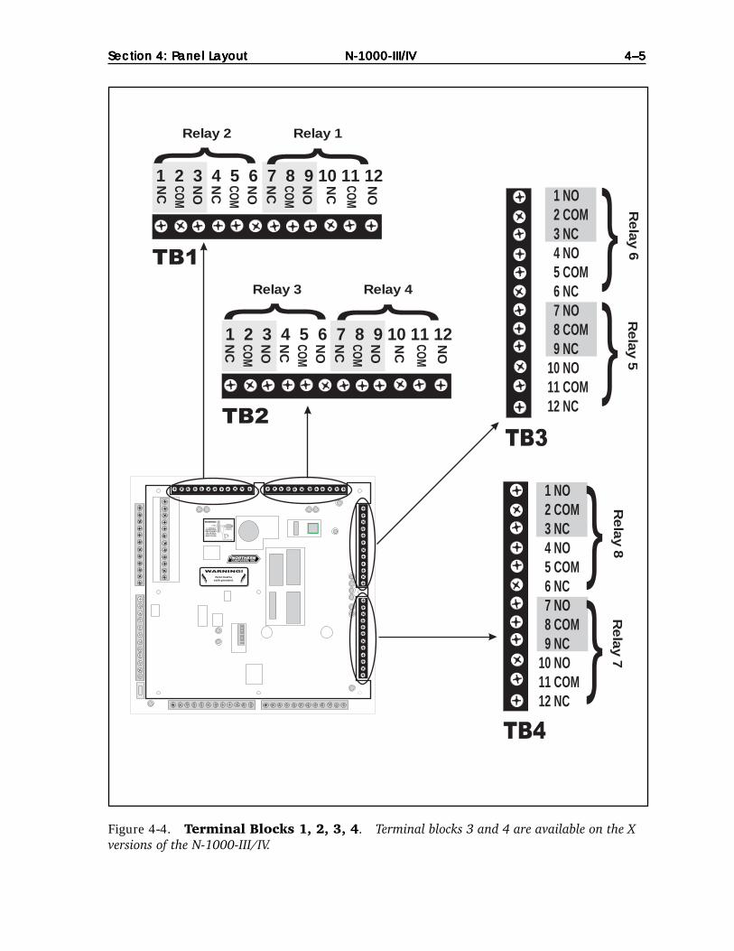
Each DPDT relay provides control for up to two external devices. Both poles of agiven relay have a normally-closed terminal, a common terminal and a normally-open terminal. (See Figure 4-4.) Northern recommends using the A pole of therelays for locks (inductive loads) and the B pole for dry circuit (logic) applica-tion.
Terminal Block 1 provides relay contacts for relays 1 and 2.
Terminal Block 2 provides relay contacts for relays 3 and 4.
Terminal Block 3 provides relay contacts for relays 5 and 6.
Terminal Block 4 provides relay contacts for relays 7 and 8.
Terminal block 1, 2, 3, 4 terminations are as follow:
Pos. TB1 TB2 TB3 TB4 Function
1 Relay 2: A Relay 3: A Relay 6: A Relay 8: A Normally-Closed2 Relay 2: A Relay 3: A Relay 6: A Relay 8: A Common3 Relay 2: A Relay 3: A Relay 6: A Relay 8: A Normally-Open
4 Relay 2: B Relay 3: B Relay 6: B Relay 8: B Normally-Closed5 Relay 2: B Relay 3: B Relay 6: B Relay 8: B Common6 Relay 2: B Relay 3: B Relay 6: B Relay 8: B Normally-Open
7 Relay 1: A Relay 4: A Relay 5: A Relay 7: A Normally-Closed8 Relay 1: A Relay 4: A Relay 5: A Relay 7: A Common9 Relay 1: A Relay 4: A Relay 5: A Relay 7: A Normally-Open
10 Relay 1: B Relay 4: B Relay 5: B Relay 7: B Normally-Closed11 Relay 1: B Relay 4: B Relay 5: B Relay 7: B Common12 Relay 1: B Relay 4: B Relay 5: B Relay 7: B Normally-Open
N-1000-III/IVN-1000-III/IVN-1000-III/IVN-1000-III/IVN-1000-III/IVSection 4: PSection 4: PSection 4: PSection 4: PSection 4: Panel Lanel Lanel Lanel Lanel Layoutayoutayoutayoutayout 4–54–54–54–54–5
Figure 4-4. Terminal Blocks 1, 2, 3, 4. Terminal blocks 3 and 4 are available on the Xversions of the N-1000-III/IV.
Panel must beearth grounded.
S-4 SUPPRESSIONREQUIRED ACROSSEVERY ACTIVE RELAYAND ELECTRICAL
DEVICE (CONNECTWITHIN 18 INCHES).
Lock Solenoid
1
3456789
10
2
1112
1 2 3 4 5 6 7 8 9 10 11 12NC
NO
COM
NC
NO
COM
NC
NO
COM
NC
NO
COM
NC
NO
COM
NC
NO
COM
NC
NO
COM
NC
NO
COM
1 2 3 4 5 6 7 8 9 10 11 12
Relay 2 Relay 1
Relay 3 Relay 4
1 NO2 COM3 NC4 NO5 COM6 NC7 NO8 COM9 NC
10 NO11 COM12 NC
Re
lay 6
Re
lay 5
1 NO2 COM3 NC4 NO5 COM6 NC7 NO8 COM9 NC
10 NO11 COM12 NC
Re
lay 8
Re
lay 7
N-1000-III/IVN-1000-III/IVN-1000-III/IVN-1000-III/IVN-1000-III/IV4–64–64–64–64–6 Section 4: PSection 4: PSection 4: PSection 4: PSection 4: Panel Lanel Lanel Lanel Lanel Layoutayoutayoutayoutayout
4-3: Terminal Block 5
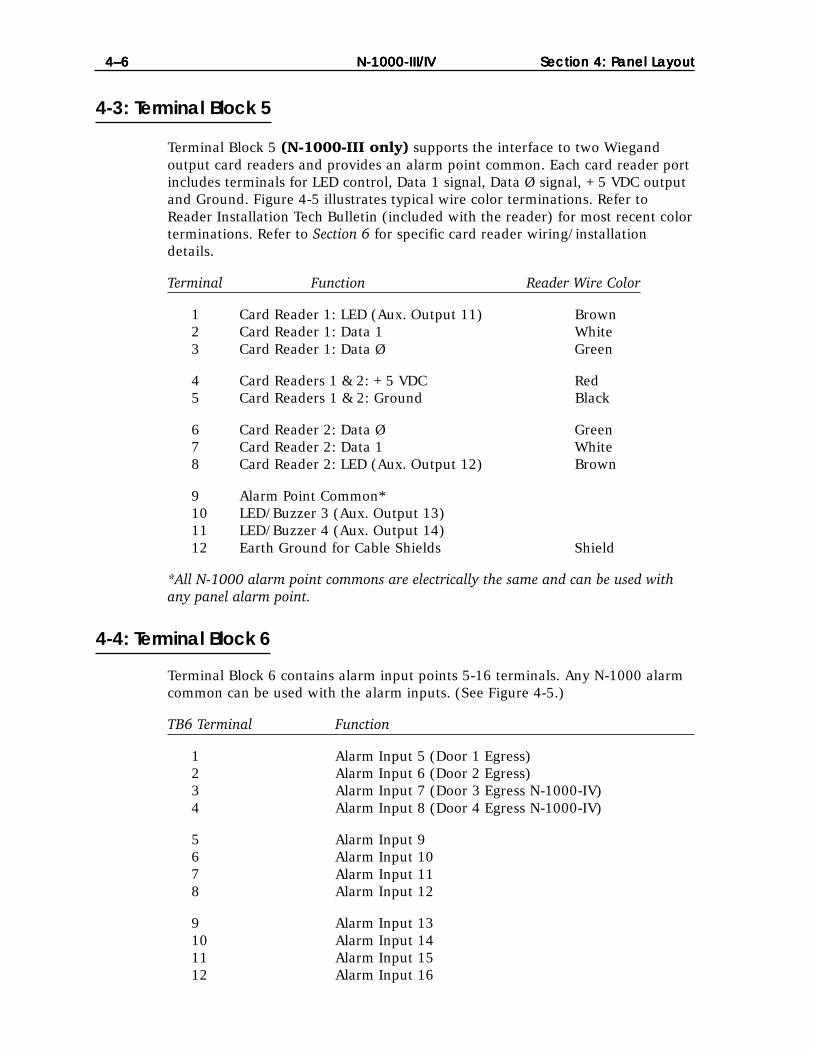
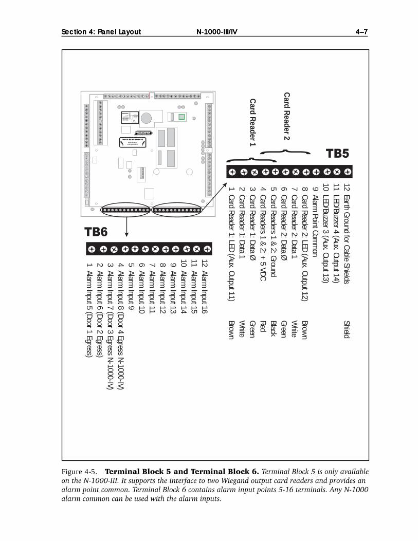
Terminal Block 5 (N-1000-III only) supports the interface to two Wiegandoutput card readers and provides an alarm point common. Each card reader portincludes terminals for LED control, Data 1 signal, Data Ø signal, +5 VDC outputand Ground. Figure 4-5 illustrates typical wire color terminations. Refer toReader Installation Tech Bulletin (included with the reader) for most recent colorterminations. Refer to Section 6 for specific card reader wiring/installationdetails.
Terminal Function Reader Wire Color
1 Card Reader 1: LED (Aux. Output 11) Brown2 Card Reader 1: Data 1 White3 Card Reader 1: Data Ø Green
4 Card Readers 1 & 2: +5 VDC Red5 Card Readers 1 & 2: Ground Black
6 Card Reader 2: Data Ø Green7 Card Reader 2: Data 1 White8 Card Reader 2: LED (Aux. Output 12) Brown
9 Alarm Point Common*10 LED/Buzzer 3 (Aux. Output 13)11 LED/Buzzer 4 (Aux. Output 14)12 Earth Ground for Cable Shields Shield
*All N-1000 alarm point commons are electrically the same and can be used withany panel alarm point.
4-4: Terminal Block 6
Terminal Block 6 contains alarm input points 5-16 terminals. Any N-1000 alarmcommon can be used with the alarm inputs. (See Figure 4-5.)
TB6 Terminal Function
1 Alarm Input 5 (Door 1 Egress)2 Alarm Input 6 (Door 2 Egress)3 Alarm Input 7 (Door 3 Egress N-1000-IV)4 Alarm Input 8 (Door 4 Egress N-1000-IV)
5 Alarm Input 96 Alarm Input 107 Alarm Input 118 Alarm Input 12
9 Alarm Input 1310 Alarm Input 1411 Alarm Input 1512 Alarm Input 16
N-1000-III/IVN-1000-III/IVN-1000-III/IVN-1000-III/IVN-1000-III/IVSection 4: PSection 4: PSection 4: PSection 4: PSection 4: Panel Lanel Lanel Lanel Lanel Layoutayoutayoutayoutayout 4–74–74–74–74–7
Figure 4-5. Terminal Block 5 and Terminal Block 6. Terminal Block 5 is only availableon the N-1000-III. It supports the interface to two Wiegand output card readers and provides analarm point common. Terminal Block 6 contains alarm input points 5-16 terminals. Any N-1000alarm common can be used with the alarm inputs.
Panel must beearth grounded.
S-4 SUPPRESSIONREQUIRED ACROSSEVERY ACTIVE RELAYAND ELECTRICAL
DEVICE (CONNECTWITHIN 18 INCHES).
Lock Solenoid
1
3456789
10
2
1112
12 Alarm Input 16
11 Alarm Input 15
10 Alarm Input 14
9 Alarm Input 13
8 Alarm Input 12
7 Alarm Input 11
6 Alarm Input 10
5 Alarm Input 9
4 Alarm Input 8 (Door 4 Egress N-1000-IV)
3 Alarm Input 7 (Door 3 Egress N-1000-IV)
2 Alarm Input 6 (Door 2 Egress)
1 Alarm Input 5 (Door 1 Egress)
12 Earth Ground for Cable ShieldsShield
11 LED/Buzzer 4 (Aux. Output 14)10 LED/Buzzer 3 (Aux. Output 13)9 Alarm
Point Comm
on8 Card Reader 2: LED (Aux. Output 12)
Brown
7 Card Reader 2: Data 1W
hite6 Card Reader 2: Data Ø
Green5 Card Readers 1 & 2: Ground
Black4 Card Readers 1 & 2: +
5 VDCRed
3 Card Reader 1: Data ØGreen
2 Card Reader 1: Data 1W
hite1 Card Reader 1: LED (Aux. Output 11)
Brown
Card R
eader 1
Card R
eader 2

N-1000-III/IVN-1000-III/IVN-1000-III/IVN-1000-III/IVN-1000-III/IV4–84–84–84–84–8 Section 4: PSection 4: PSection 4: PSection 4: PSection 4: Panel Lanel Lanel Lanel Lanel Layoutayoutayoutayoutayout
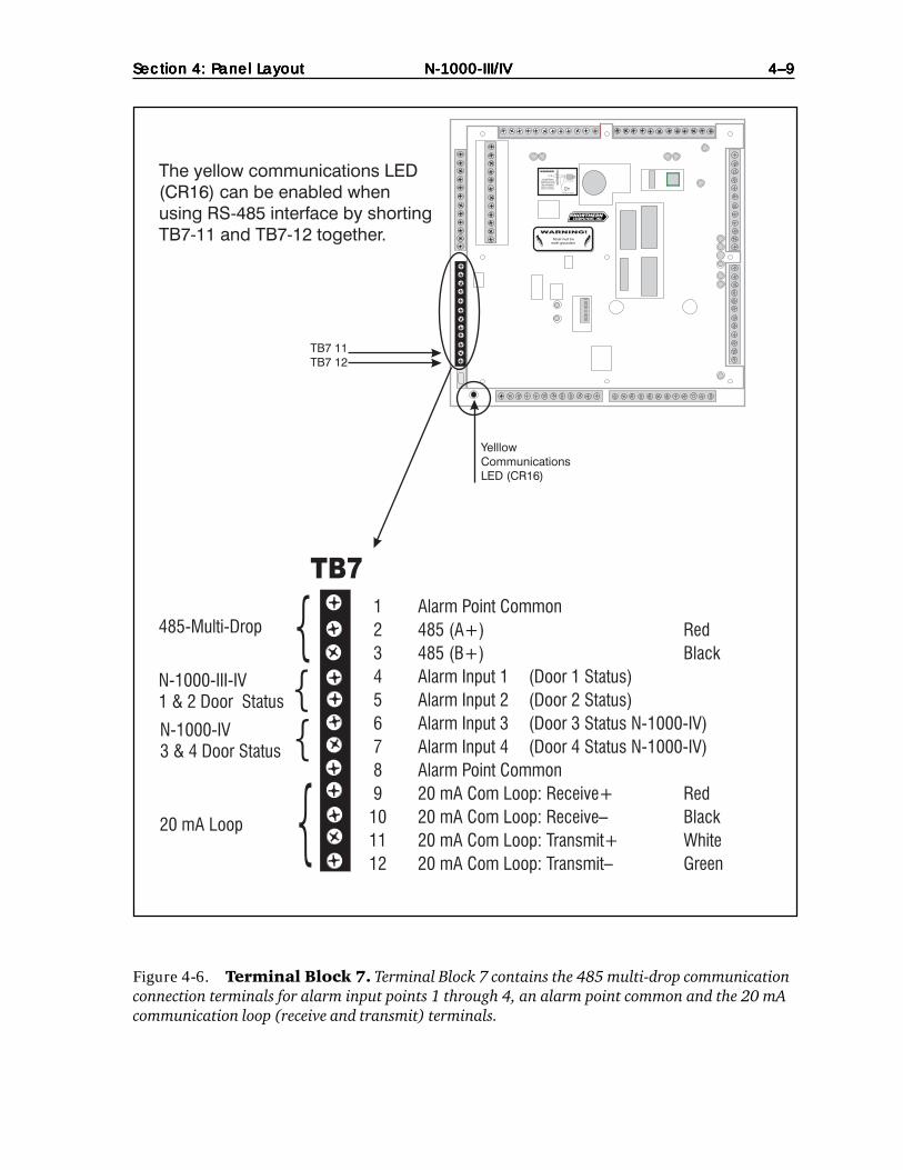
4-5: Terminal Block 7
Terminal Block 7 contains the 485 multi-drop communication connection, terminalsfor alarm input points 1 through 4, an alarm point common and the 20 mA com-munication loop (receive and transmit) terminals as illustrated in Figure 4-6.
NOTE: The yellow communications LED (CR16) can be enabled when using RS-485interface by shorting TB7-11 and TB7-12 together.
Jumper settings on the panel are used to select either the 485 multi-drop or the20 mA communications mode. The last panel on the 485 multi-drop cable mustbe properly configured. Refer to Section 4-9, Jumpers, for further information.
The 20 mA communication protocol specifications are as follow:ASCII text characters8 data bits1 stop bitNo parity(Refer to Section 4-8 for baud rate settings.)
Terminal Function Wire Color(s)1 Alarm Point Common*
2 485 multi-drop (A+) Red3 485 multi-drop (B+) Black
4 Alarm Input 1 (Door 1 status)5 Alarm Input 2 (Door 2 status)6 Alarm Input 3 (Door 3 status N-1000-IV)7 Alarm Input 4 (Door 4 status N-1000-IV)
8 Alarm Point Common*
9 20 mA Communication Loop: Receive+ Red10 20 mA Communication Loop: Receive– Black11 20 mA Communication Loop: Transmit+ White12 20 mA Communication Loop: Transmit– Green
*All N-1000 alarm point commons are electrically the same and can be used withany panel alarm points.
N-1000-III/IVN-1000-III/IVN-1000-III/IVN-1000-III/IVN-1000-III/IVSection 4: PSection 4: PSection 4: PSection 4: PSection 4: Panel Lanel Lanel Lanel Lanel Layoutayoutayoutayoutayout 4–94–94–94–94–9
Figure 4-6. Terminal Block 7. Terminal Block 7 contains the 485 multi-drop communicationconnection terminals for alarm input points 1 through 4, an alarm point common and the 20 mAcommunication loop (receive and transmit) terminals.
N-1000-III/IVN-1000-III/IVN-1000-III/IVN-1000-III/IVN-1000-III/IV4–104–104–104–104–10 Section 4: PSection 4: PSection 4: PSection 4: PSection 4: Panel Lanel Lanel Lanel Lanel Layoutayoutayoutayoutayout
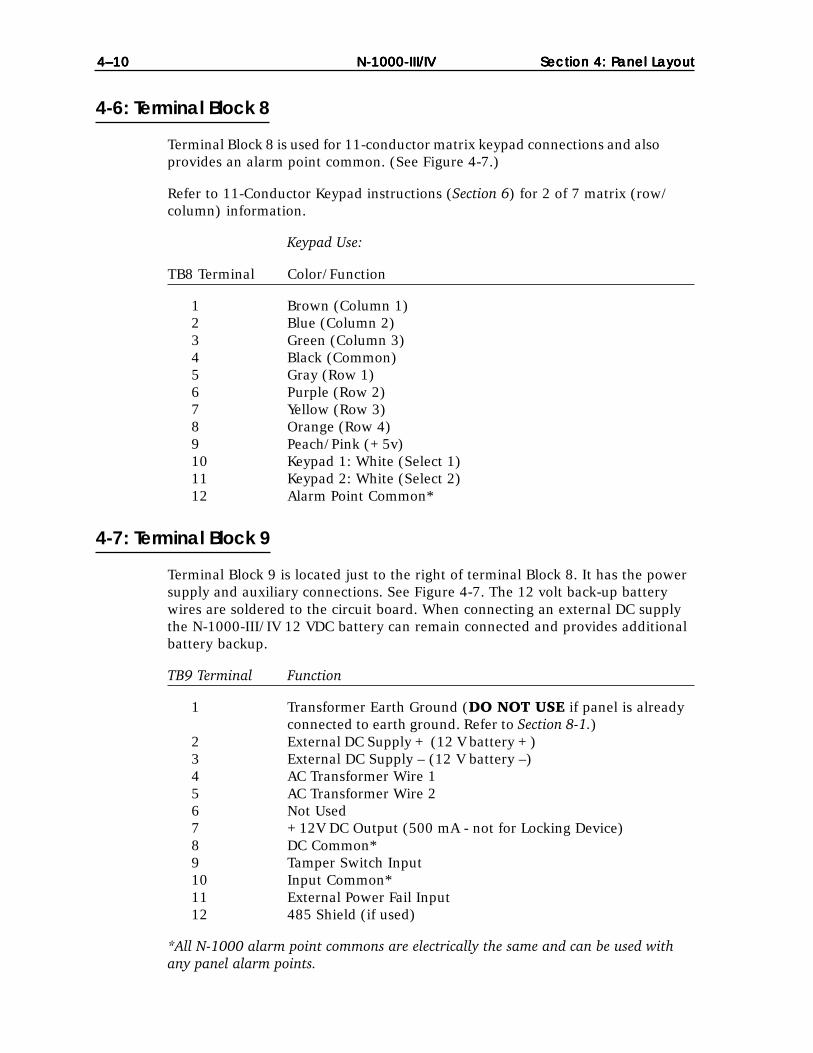
4-6: Terminal Block 8
Terminal Block 8 is used for 11-conductor matrix keypad connections and alsoprovides an alarm point common. (See Figure 4-7.)
Refer to 11-Conductor Keypad instructions (Section 6) for 2 of 7 matrix (row/column) information.
Keypad Use:
TB8 Terminal Color/Function
1 Brown (Column 1)2 Blue (Column 2)3 Green (Column 3)4 Black (Common)5 Gray (Row 1)6 Purple (Row 2)7 Yellow (Row 3)8 Orange (Row 4)9 Peach/Pink (+5v)10 Keypad 1: White (Select 1)11 Keypad 2: White (Select 2)12 Alarm Point Common*
4-7: Terminal Block 9
Terminal Block 9 is located just to the right of terminal Block 8. It has the powersupply and auxiliary connections. See Figure 4-7. The 12 volt back-up batterywires are soldered to the circuit board. When connecting an external DC supplythe N-1000-III/IV 12 VDC battery can remain connected and provides additionalbattery backup.
TB9 Terminal Function
1 Transformer Earth Ground (DO NOT USE if panel is alreadyconnected to earth ground. Refer to Section 8-1.)
2 External DC Supply + (12 V battery +)3 External DC Supply – (12 V battery –)4 AC Transformer Wire 15 AC Transformer Wire 26 Not Used7 +12V DC Output (500 mA - not for Locking Device)8 DC Common*9 Tamper Switch Input10 Input Common*11 External Power Fail Input12 485 Shield (if used)
*All N-1000 alarm point commons are electrically the same and can be used withany panel alarm points.

N-1000-III/IVN-1000-III/IVN-1000-III/IVN-1000-III/IVN-1000-III/IVSection 4: PSection 4: PSection 4: PSection 4: PSection 4: Panel Lanel Lanel Lanel Lanel Layoutayoutayoutayoutayout 4–114–114–114–114–11
Figure 4-7. Terminal Blocks 8 & 9. Terminal Block 8 is used for 11-conductor matrixkeypad connections and also provides an alarm point common. Terminal Block 9 is located justto the right of Terminal Block 8. It has the power supply and auxiliary connections.

N-1000-III/IVN-1000-III/IVN-1000-III/IVN-1000-III/IVN-1000-III/IV4–124–124–124–124–12 Section 4: PSection 4: PSection 4: PSection 4: PSection 4: Panel Lanel Lanel Lanel Lanel Layoutayoutayoutayoutayout
4-8: DIP Switch Settings
N-1000-III/IV DIP switch positions 1 and 2 control the panel baud rate for the 20mA Loop. Set the panel baud rate to match that of the system programmingdevice. 1200 baud is recommended for computer and data terminal systems. For485 communications use the 4800 baud setting.
N-1000-III/IV DIP switch positions 3 through 8 determine a control panel’s address.(See Figure 4-8.) Each control panel in the communication loop must have a uniqueaddress to allow unique referencing during system programming. When running thepanel’s self-test, set all DIP switches to the On position before restarting the panel.(For details of the self-test, refer to Appendix C: Trouble Shooting.)
Baud rate and panel address DIP switch settings are as follow:
Baud Rate 1 2 Panel No. 3 4 5 6 7 8
1200 Off Off 1 On On On On On Off2400 Off On 2 On On On On Off On4800 On On 3 On On On On Off Off9600 On Off 4 On On On Off On On
5 On On On Off On Off 6 On On On Off Off On 7 On On On Off Off Off 8 On On Off On On On 9 On On Off On On Off 10 On On Off On Off On 11 On On Off On Off Off 12 On On Off Off On On 13 On On Off Off On Off 14 On On Off Off Off On 15 On On Off Off Off Off 16 On Off On On On On 17 On Off On On On Off 18 On Off On On Off On
Figure 4-8. DIP Switches. Switch positions 1 and 2 control the panel baud rate for the 20mA loop; switch positions 3 through 8 determine the control panel’s address. The positions aboveare set for panel 1 and a baud rate of 2400.
Panel must beearth grounded.
S-4 SUPPRESSIONREQUIRED ACROSSEVERY ACTIVE RELAYAND ELECTRICAL
DEVICE (CONNECTWITHIN 18 INCHES).
Lock Solenoid
1
3456789
10
2
1112
1
2
3
4
5
6
7
8
1
2
3
4
5
6
7
8
ON
Baud Rate
Panel Address

N-1000-III/IVN-1000-III/IVN-1000-III/IVN-1000-III/IVN-1000-III/IVSection 4: PSection 4: PSection 4: PSection 4: PSection 4: Panel Lanel Lanel Lanel Lanel Layoutayoutayoutayoutayout 4–134–134–134–134–13
Panel 3 4 5 6 7 8
19 On Off On On Off Off20 On Off On Off On On21 On Off On Off On Off22 On Off On Off Off On23 On Off On Off Off Off24 On Off Off On On On25 On Off Off On On Off26 On Off Off On Off On27 On Off Off On Off Off28 On Off Off Off On On29 On Off Off Off On Off30 On Off Off Off Off On31 On Off Off Off Off Off32 Off On On On On On33 Off On On On On Off34 Off On On On Off On35 Off On On On Off Off36 Off On On Off On On37 Off On On Off On Off38 Off On On Off Off On39 Off On On Off Off Off40 Off On Off On On On41 Off On Off On On Off42 Off On Off On Off On43 Off On Off On Off Off44 Off On Off Off On On45 Off On Off Off On Off46 Off On Off Off Off On47 Off On Off Off Off Off48 Off Off On On On On49 Off Off On On On Off50 Off Off On On Off On51 Off Off On On Off Off52 Off Off On Off On On53 Off Off On Off On Off54 Off Off On Off Off On55 Off Off On Off Off Off56 Off Off Off On On On57 Off Off Off On On Off58 Off Off Off On Off On59 Off Off Off On Off Off60 Off Off Off Off On On61 Off Off Off Off On Off62 Off Off Off Off Off On63 Off Off Off Off Off Off
NOTE: For DIP switches with OPEN/CLOSED notation:OPEN=Off CLOSED=On
NOTE: The restart button MUST be pressed to activate a change made to anyDIP switch setting (for baud rate and/or panel address). Pressing the restartbutton DOES NOT alter N-1000-III/IV database memory.
NOTE: Addresses 32 andabove cannot be usedwith the 485 multi-drop.

N-1000-III/IVN-1000-III/IVN-1000-III/IVN-1000-III/IVN-1000-III/IV4–144–144–144–144–14 Section 4: PSection 4: PSection 4: PSection 4: PSection 4: Panel Lanel Lanel Lanel Lanel Layoutayoutayoutayoutayout
4-9: Jumpers
There are several jumpers on the circuit board (Figure 4-9) which configure thepanel for various modes of operation as indicated below:
Number Position Function
JP1 Jump Pins 1 & 2 Select 20 mA communications loop.
Jump Pins 2 & 3 Select 485 multi-drop communications (default).
JP2 Open Provide end of line (EOL) termination forJP3 Open 485 drop line. Refer to Section 6-6-8 for details.
JP4 Jump Pins 1 & 2 Jumper is on for the panel at the end of the 485multi-drop cable (default).
Remove Remove the jumper if the panel is not at the endof the cable or JP2 and JP3 are used. Refer toSection 6-6-8 for details.
JP5 (Not Used)
JP6 Jump pins 2 & 3 Select onboard power status detection (default).
Jump Pins 1 & 2 Select external power status detection.
JP7 (Not Used)
JP8 (Not Used)
JP9 Jump Pins 1 & 2 Disable clearing of RAM by JP10 (default).
Remove Enable clearing the RAM by JP10.
JP10 Jump Pins 1 & 2 Clears RAM when power is off for at least 60seconds and JP9 is removed.
Remove Will not clear RAM, allows supercap to backupmemory (default).
JP11 (Not Used)

N-1000-III/IVN-1000-III/IVN-1000-III/IVN-1000-III/IVN-1000-III/IVSection 4: PSection 4: PSection 4: PSection 4: PSection 4: Panel Lanel Lanel Lanel Lanel Layoutayoutayoutayoutayout 4–154–154–154–154–15
Figure 4-9. Configuration Jumpers and Connectors. The N-1000-III/IV panelsprovide for either 485 multi-drop communication or 20 mA communication loops. These modesare selected by changing jumper settings.
4-10: Connectors
Connector Function
Battery Wires Red and Black wires soldered to the circuit board with fast-onconnectors for the 12 volt backup battery
J1 Four pin connector for the AEP-3 (Revision A) RelayExpansion Board(s)
J2 Eight pin connector for the AEP-3 (Revision B) RelayExpansion Board(s)
Panel must beearth grounded.
S-4 SUPPRESSIONREQUIRED ACROSSEVERY ACTIVE RELAYAND ELECTRICAL
DEVICE (CONNECTWITHIN 18 INCHES).
Lock Solenoid
1
3456789
10
2
1112
Jumpers 2, 3 & 4
Jumper 1
Jumper 10
Jumper 9
Jumper 6
Jumpers 5, 7, 8, and11 are not used.
Battery Wires withfast-on connectors
J2 AEP-3Rev. B Connector
J1 AEP-3Rev. A Connector
N-1000-III/IV

N-1000-III/IVN-1000-III/IVN-1000-III/IVN-1000-III/IVN-1000-III/IV4–164–164–164–164–16 Section 4: PSection 4: PSection 4: PSection 4: PSection 4: Panel Lanel Lanel Lanel Lanel Layoutayoutayoutayoutayout
4-11: LEDs
The functions of the N-1000-III/IV LEDs are listed below and also illustrated inFigure 4-10. When an LED is lit it indicates that its relay is energized, that is thenormally open relay contacts become closed and the normally closed relaycontacts become open. Not lit indicates relay is de-energized, that is normallyopen and normally closed contacts are in normal state.
Function LED Color Lit IndicatesOutput Relay 1 Indicator: 1 Red Energized
Output Relay 2 Indicator: 2 Red Energized
Output Relay 3 Indicator: 3 Red Energized
Output Relay 4 Indicator: 4 Red Energized
Output Relay 5 Indicator: 5 Red Energized
Output Relay 6 Indicator: 6 Red Energized
Output Relay 7 Indicator: 7 Red Energized
Output Relay 8 Indicator: 8 Red Energized
485 Status: 9 Green Slow flashing indicates proper 485communications
+12 VDC Indicator: 10 Green 12 V DC external power is available
+5 VDC Indicator: 11 Green Panel is supplying +5 VDC output forreader/keypad power
Low-Voltage OK: 12 Green Battery voltage acceptable and RAMback-up available
Input Ground: 13 Red Ground fault detected
Run: 14 Green Pulsing indicates N-1000 microprocessoroperating properly (not lit or notpulsing indicates malfunction)
Power Status: 15 Red Loss of primary power with panelpowered by 12 VDC battery (fastflashing indicates battery charge is toolow to operate panel even withprimary power available)
Com Loop Indicator: 16 Yellow Loop current is present (flashing offindicates data flow)
485-TX: 17 Red Periodic quick flashing indicates 485communications link functioningproperly
Four Reader Board Status Green Quick flash indicates processorrunning, long flash indicates cardread, very long flash indicates resetdue to error or power problem
*indicator turns off at approx. 10 volts, the panel shuts down at approx. 9.9 volts

N-1000-III/IVN-1000-III/IVN-1000-III/IVN-1000-III/IVN-1000-III/IVSection 4: PSection 4: PSection 4: PSection 4: PSection 4: Panel Lanel Lanel Lanel Lanel Layoutayoutayoutayoutayout 4–174–174–174–174–17
Figure 4-10. LED Functions. When an LED is lit it indicates that its relay is energized, thatis, the normally open relay contacts become closed and the normally closed relay contactsbecome open. Not lit indicates relay is de-energized, that is normally open and normally closedcontacts are in normal state.

N-1000-III/IVN-1000-III/IVN-1000-III/IVN-1000-III/IVN-1000-III/IV4–184–184–184–184–18 Section 4: PSection 4: PSection 4: PSection 4: PSection 4: Panel Lanel Lanel Lanel Lanel Layoutayoutayoutayoutayout
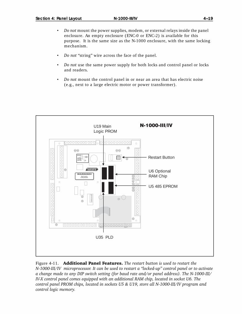
4-12: Restart Button
The restart button is used to restart the N-1000-III/IV microprocessor. (See Figure4-11.) Press the restart button to restart a “locked-up” control panel and to activatea change made to any DIP switch setting (for baud rate and/or panel address).
The panel’s self-test feature can be activated by setting all of the DIP switches tothe On position and then depressing the Restart button. For details of the self-test,refer to Appendix C: Troubling Shooting.
Pressing the Restart button DOES NOT alter N-1000-III/IV database memory. Thedata base can be completely cleared by the following method: Disconnect the ACpower and battery back-up. Move jumper JP9 to position JP10 for one minutethen return it to JP9. Restore the power connections.
4-13: RAM Chip
Control panel RAM chips store all database and transaction buffer memory. TheN-1000-III/IV control panels use a single RAM chip with the option of an addi-tional chip in socket U6. The N-1000-III/IV-X control panels come equipped withan extra RAM chip. (See Figure 4-11.)
NOTE: Control panel card database and transaction buffer capacities are deter-mined by the number of RAM chips used and can be modified by use of the Ucommand I option. Refer to Appendix A: Programming Quick Reference Guidefor details.
4-14: PROM Chip
The control panel PROM chips store all N-1000-III/IV program and control logicmemory and are located in sockets U5 & U19. (See Figure 4-11.) On each PROMis a sticker which indicates the socket number and the firmware version of thechip. Refer to the main PROM number when referencing the N-1000-III/IVProgramming Manual for specific programming/operation functions.
4-15: Additional Installation Information
Northern Computers recommends the following installation techniques for theN-1000 panels:
DO• Do run all wiring for door locks/strikes and panel primary power in a sepa-
rate conduit or allow at least 12 inches of space between the power cablesand the data/reader cables.
• Do use shielded cables or metal conduit when necessary to reduce interferingradio frequency emissions.
DO NOT
N-1000-III/IVN-1000-III/IVN-1000-III/IVN-1000-III/IVN-1000-III/IVSection 4: PSection 4: PSection 4: PSection 4: PSection 4: Panel Lanel Lanel Lanel Lanel Layoutayoutayoutayoutayout 4–194–194–194–194–19
Figure 4-11. Additional Panel Features. The restart button is used to restart theN-1000-III/IV microprocessor. It can be used to restart a “locked-up” control panel or to activatea change made to any DIP switch setting (for baud rate and/or panel address). The N-1000-III/IV-X control panel comes equipped with an additional RAM chip, located in socket U6. Thecontrol panel PROM chips, located in sockets U5 & U19, store all N-1000-III/IV program andcontrol logic memory.
Panel must beearth grounded.
S-4 SUPPRESSIONREQUIRED ACROSSEVERY ACTIVE RELAYAND ELECTRICAL
DEVICE (CONNECTWITHIN 18 INCHES).
LLoocckk SSoolleennooiidd
11
33445566778899
1010
22
11111212
N-1000-III/IV
Reader 1 Reader 2
Restart Button
U6 OptionalRAM Chip
U19 MainLogic PROM
U35 PLD
U5 485 EPROM
• Do not mount the power supplies, modem, or external relays inside the panelenclosure. An empty enclosure (ENC-0 or ENC-2) is available for thispurpose. It is the same size as the N-1000 enclosure, with the same lockingmechanism.
• Do not “string” wire across the face of the panel.
• Do not use the same power supply for both locks and control panel or locksand readers.
• Do not mount the control panel in or near an area that has electric noise(e.g., next to a large electric motor or power transformer).
N-1000-III/IVN-1000-III/IVN-1000-III/IVN-1000-III/IVN-1000-III/IV4–204–204–204–204–20 Section 4: PSection 4: PSection 4: PSection 4: PSection 4: Panel Lanel Lanel Lanel Lanel Layoutayoutayoutayoutayout
Panel must beearth grounded.
S-4 SUPPRESSIONREQUIRED ACROSSEVERY ACTIVE RELAYAND ELECTRICAL
DEVICE (CONNECTWITHIN 18 INCHES).
1 Brown2 Blue3 Green4 Black5 Gray6 Purple7 Yellow8 Orange9 Pink/Peach
10 White
9 Red10 Black11 White12 Green
5 Black
4 Red
3 Green
2 White
1 Brow
n
TB1
TB7
TB8
TB9
N-1000-III
MagneticLock
Key padKP-10
12 VBatteryBAT-3
C100-A-1
TransformerX-4
4 AC One
5 AC Two
Normally OpenSwitch heldclosed by door 4 Alarm One
24 VDC
Lock PowerSupply
–
+
7 Norm
ally Closed
8 Com
mon
EnclosureEarth GroundStud
To PCormodem
+ Red
– Black
Shield
TB6
TB2
TB3
TB4
TB5(N-1000-III only)
Red
DoorStatusSwitch
Card ReaderCR1
EgressSwitch
NormallyClosedSwitch
S-4 Suppresser
NOTE: Seperate FireRelease Contact is required.
16.5 V
8 Common
Inpu
t Fiv
e
Com
mon
S-4 Suppresser
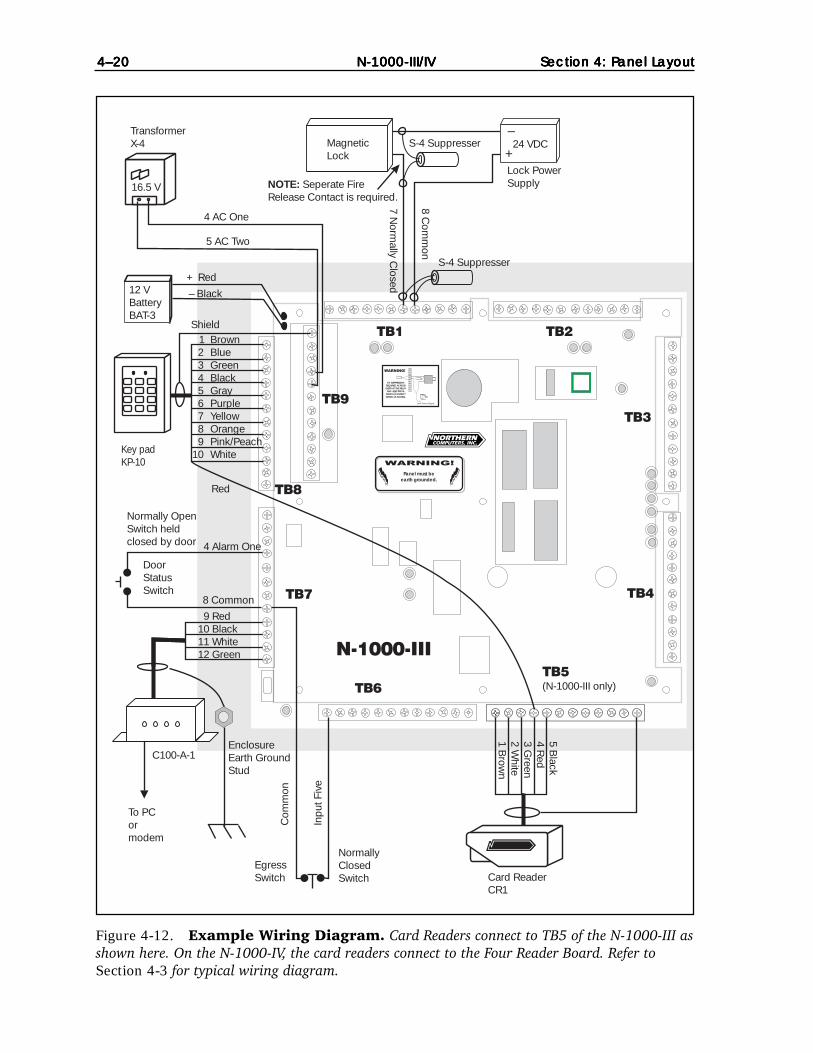
Figure 4-12. Example Wiring Diagram. Card Readers connect to TB5 of the N-1000-III asshown here. On the N-1000-IV, the card readers connect to the Four Reader Board. Refer toSection 4-3 for typical wiring diagram.

Section 5: OperationSection 5: OperationSection 5: OperationSection 5: OperationSection 5: Operation N-1000-III/IV N-1000-III/IV N-1000-III/IV N-1000-III/IV N-1000-III/IV 5–15–15–15–15–1
Section 5: Operation
5-1: Card Reader/Keypad Operation
Some card readers require that a format (software) command be programmed intothe host N-1000-III/IV controller before cards can be read. If the format commandis not programmed into the control panel, these readers or keypads will not trans-mit card numbers to the terminal/printer. Refer to Appendix A: Programming QuickReference Guide for complete F Command format listings.
Verify card reader/keypad operation before programming. Codes need not beprogrammed into memory to verify reader/keypad operation. When a code isentered or a card presented, it should appear on the display/printer, followed byan NF or not found message.
The control panel continuously monitors the card reader and keypad ports forcode use. Access is restricted by placing time zone limitations on the codes inuse, NOT by time zone controlling (disabling) the reading devices.
Card reader or keypad activation of output points is determined by the presenceor absence of the anti-passback option in panel memory. Refer to I Command, AOption in Appendix A for further information.
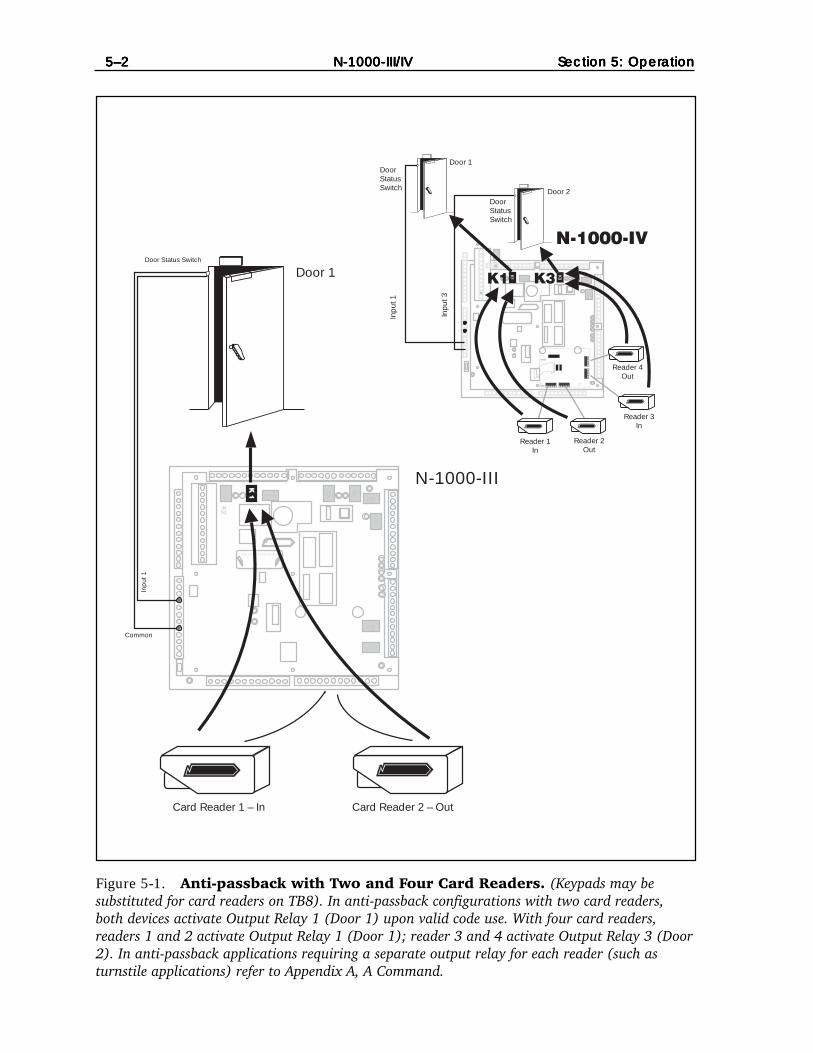
In anti-passback configurations with two card readers or two keypads, bothdevices activate Output Relay 1 (Door 1) upon valid code use (Figure 5-1). Inanti-passback applications requiring a separate output relay for the reader (suchas turnstile applications), refer to A Command in Appendix A.
In configurations WITHOUT anti-passback enabled, Card Reader or Keypad 1activates Output Relay 1 (Door 1) and Card Reader or Keypad 2 activates OutputRelay 2 (Door 2) (Figure 5-2).
Card readers and keypads can be reassigned to activate a specified input point,output point or group (multiple outputs) upon valid code use, via theA Command. Refer to Appendix A.
5–25–25–25–25–2 N-1000-III/IVN-1000-III/IVN-1000-III/IVN-1000-III/IVN-1000-III/IV Section 5: OperationSection 5: OperationSection 5: OperationSection 5: OperationSection 5: Operation
Figure 5-1. Anti-passback with Two and Four Card Readers. (Keypads may besubstituted for card readers on TB8). In anti-passback configurations with two card readers,both devices activate Output Relay 1 (Door 1) upon valid code use. With four card readers,readers 1 and 2 activate Output Relay 1 (Door 1); reader 3 and 4 activate Output Relay 3 (Door2). In anti-passback applications requiring a separate output relay for each reader (such asturnstile applications) refer to Appendix A, A Command.
WARNING!
K3
K4
K 1
K 1
K5
K10 K6
K7
K8
K2
N-1000-III
Card Reader 2 – Out
Common
Card Reader 1 – In
Inpu
t 1
Door Status SwitchK
3K
3
K4
K1
K1
K5
K10 K6
K2
K2
Reader 1Reader 1
To N-1000To N-1000
K3K1
Reader 1In
Reader 3In
N-1000-IV
Inpu
t 1
Inpu
t 3
Door 2
Door 1
Reader 2Out
Reader 4Out
DoorStatusSwitch
DoorStatusSwitch
Door 1

Section 5: OperationSection 5: OperationSection 5: OperationSection 5: OperationSection 5: Operation N-1000-III/IV N-1000-III/IV N-1000-III/IV N-1000-III/IV N-1000-III/IV 5–35–35–35–35–3
Figure 5-2. Two and Four Card Readers without Anti-passback. In configurationsWITHOUT anti-passback enabled, card reader 1 activates Output Relay 1 (Door 1) and cardreader or keypad 2 activates Output Relay 2 (Door 2). With four readers, card readers 1, 2, 3,and 4 activate output relays 1, 2, 3, and 4 activating doors 1, 2, 3, and 4 respectively.
Lock Solenoid
34567
910
2
12
K 1
K 1
N-1000-III
K 2
K 2
Door 2
Card Reader 2
Door 1
Card Reader 1
Inpu
t1
Poi
nt
Common
Inpu
t P
oint
2
Panel must beearth grounded.Panel must be
earth grounded.
S-4 SUPPRESSIONREQUIRED ACROSSEVERY ACTIVE RELAYAND ELECTRICAL
DEVICE (CONNECTWITHIN 18 INCHES).
S-4 SUPPRESSIONREQUIRED ACROSSEVERY ACTIVE RELAYAND ELECTRICAL
DEVICE (CONNECTWITHIN 18 INCHES).
Lock Solenoid
1
3456789
10
2
1112
ShieldGND+5vDØD1LED
ShieldGND+5vDØD1LED
ShieldGND+5vDØD1LED
ShieldGND+5vDØD1LED
LED D1 DØ +5v GND ShieldLED D1 DØ +5v GND Shield LED D1 DØ +5v GND ShieldLED D1 DØ +5v GND Shield
StatusLED
StatusLED Northern Computers, Inc.Northern Computers, Inc.
Reader 1Reader 1 Reader 2Reader 2
Reader 3Reader 3
Reader 4Reader 4
To N-1000To N-1000
N-1000-IVDoor 2
K3K1
Door 1
Reader 1 Reader 2
Reader 3
Reader 4
K1
K2
K2K
3
K4
K4
Door 4
Door 3
Door StatusSwitch
Door StatusSwitch
Doo
r S
tatu
sS
witc
h
Doo
r S
tatu
sS
witc
h
Doo
r S
tatu
sS
witc
h
Doo
r S
tatu
sS
witc
h

5–45–45–45–45–4 N-1000-III/IVN-1000-III/IVN-1000-III/IVN-1000-III/IVN-1000-III/IV Section 5: OperationSection 5: OperationSection 5: OperationSection 5: OperationSection 5: Operation
5-2: Alarm Input Points
All N-1000 alarm input points default to normally-closed, non-supervised circuitsused to monitor changes of state. N-1000-III/IV inputs can also be configured fornormally-open circuits and 3-state supervised circuits. Input points have both aphysical state and a software state, as described below:
Physical StateInput points have physical states of OPEN and CLOSED. An open input is consideredto be in ALARM condition. A closed input is considered to be in NORMALcondition.
Software StateInput points have software states of UNSHUNTED (active) and SHUNTED (notactive). When an input is unshunted, all physical changes of state (openings andclosures) are recognized. When an input is shunted, physical changes of state are
Figure 5-3. Input Point configuration.
N-1000-III/IV Input Configurations
Input Condition Input Status
1. Non-Supervised Normally Closed Circuit (default)Shorted NormalOpen AlarmResistance* Trouble
2. Non-Supervised Normally Open CircuitShorted AlarmOpen NormalResistance* Trouble
3. 3-State Supervised Normally Closed CircuitShorted TroubleOpen AlarmResistance Normal
4. 3-State Supervised Normally Open CircuitShorted AlarmOpen TroubleResistance Normal
Normally open circuit
Normally closed circuit
Normally open circuit
input
common
input
common
input
common
Normally closed circuit
input
common
2.2 K ohm 5%
2.2 K ohm 5%
*Unusually high resistance or the presence of an EOL resistor will result in a trouble status.
Section 5: OperationSection 5: OperationSection 5: OperationSection 5: OperationSection 5: Operation N-1000-III/IV N-1000-III/IV N-1000-III/IV N-1000-III/IV N-1000-III/IV 5–55–55–55–55–5
not recognized. Input shunting is software controlled and does not involve aphysical change of state of the input.
The default software state of all input points is unshunted. No programming isnecessary to keep inputs in the default state. Programming is only necessary toshunt input points.
Input Points are assigned both shunt time and time zone parameters, asdescribed below:
Shunt TimeThe shunt time parameter defines the amount of time the input point is shunted(deactivated) when triggered, such as upon valid code use.
Time ZoneThe time zone parameter defines the time the input point is automaticallyshunted (deactivated).
5-3: Relay Output Points
All N-1000-III/IV relay output points have both normally-open and normally-closed contacts, used to switch (activate/deactivate) electrical devices. Outputpoints have only a physical state, as described below:
Physical State
Output points have physical states of DE-ENERGIZED and ENERGIZED. When anoutput is de-energized, normally-open and normally-closed contacts are innormal state. When an output is energized, normally-open contacts becomeclosed and normally-closed contacts become open.
The default state of all output points is de-energized. No programming is necessaryto keep outputs in the default state. Programming is only necessary to energizeoutput points.
Door locks MUST be wired such that the following conditions are met:
1. DE-ENERGIZED relay outputs (default state ) result in LOCKED doors.
2. ENERGIZED relay outputs result in UNLOCKED doors.
NOTE: The appropriate side of the relay contact (normally-open or normally-closed) MUST be used to satisfy the conditions stated.
Output points are assigned both pulse time and time zone parameters, asdescribed below:
Pulse TimeThe pulse time parameter defines the amount of time the output point isenergized when triggered, such as upon valid code use.

5–65–65–65–65–6 N-1000-III/IVN-1000-III/IVN-1000-III/IVN-1000-III/IVN-1000-III/IV Section 5: OperationSection 5: OperationSection 5: OperationSection 5: OperationSection 5: Operation
Time ZoneThe time zone parameter defines the time the output is automatically energized.
Outputs 11 & 12 control Card Reader 1 and Card Reader 2 LEDs, respectively. Onthe N-1000-IV panel, outputs 13 & 14 control Card Reader 3 and Card Reader 4LEDs, respectively. Card reader LEDs change state upon valid code use for theduration of the programmed pulse time. Default pulse time for LED outputs istwo seconds. Refer to Appendix A, I Command, M Option and V Command forfurther card reader LED information.
5-4: Default Input Point/Output Point Interaction
The actions of all input points and output points are independent of one another,unless otherwise programmed. Selected inputs and outputs can be programmedto interact with one another through an interlocking option (refer to Appendix A,P Command as well as I Command, E Option). Interlocking allows an input pointor output point to take a specified action, based upon another input point oroutput point change of state.
The reserved input and output points, default interlocks, default pulse times anddefault shunt times for various system configurations (without anti-passback,with anti-passback and with free egress) are shown below:
Configurations WITHOUT Anti-Passback
Input Point Reserved for: Default shunt time
Input 1 Door position switch for Door 1 15 secondsInput 2 Door position switch for Door 2 15 secondsInput 3* Door position switch for door 3 15 secondsInput 4* Door position switch for door 4 15 seconds
Output Point Reserved for: Default pulse time
Output 1 Door lock for Door 1 10 seconds
Output 2 Door lock for Door 2 10 secondsOutput 3* Door lock for door 3 10 secondsOutput 4* Door lock for door 4 10 seconds
Output 11 Reader 1 LED 2 secondsOutput 12 Reader 2 LED 2 secondsOutput 13* Reader 3 LED 2 secondsOutput 14* Reader 4 LED 2 seconds
*N-1000-IV only
Output 1 is interlocked to Input 1. An activation of Output 1 (such as upon validcode use at card reader/keypad 1) causes Input 1 to be shunted for the durationof its shunt time.
Similarly, outputs 2, 3 and 4 are interlocked to inputs 2, 3 and 4 respectively.Activation of an interlocked output causes the respective interlocked input to beshunted for the duration of its shunt time. (See Figure 5-4.)

Section 5: OperationSection 5: OperationSection 5: OperationSection 5: OperationSection 5: Operation N-1000-III/IV N-1000-III/IV N-1000-III/IV N-1000-III/IV N-1000-III/IV 5–75–75–75–75–7
Figures 5-4. Interlocked Input/Output on Doors Without Anti-passback.Example: Valid code use at card reader (or keypad) 1 triggers the pulse time of Output Relay 1,unlocking Door 1 for 10 seconds and pulsing the reader LED for 2 seconds.The activation of Output 1 triggers the shunt time of Input 1 (via interlock) shunting Door 1status switch for 15 seconds.
Lock Solenoid
34567
910
2
12
K 1
K 1 N-1000-IIIK 2
K 2
Door 2
Card Reader 2
Door 1
Card Reader 1
Inpu
t P
oint
1
Common
Inpu
t P
oint
2
Lock Solenoid
1
3456789
10
2
1112
ShieldGND+5vDØD1LED
ShieldGND+5vDØD1LED
ShieldGND+5vDØD1LED
ShieldGND+5vDØD1LED
LED D1 DØ +5v GND ShieldLED D1 DØ +5v GND Shield LED D1 DØ +5v GND ShieldLED D1 DØ +5v GND Shield
StatusLED
StatusLED Northern Computers, Inc.Northern Computers, Inc.
Reader 1Reader 1 Reader 2Reader 2
Reader 3Reader 3
Reader 4Reader 4
To N-1000To N-1000
N-1000-IVDoor 2
K3K1K1
Door 1
Reader 1 Reader 2
Reader 3
Reader 4
K1
K2
K2K
3
K4
K4
Door 4
Door 3
Output Point(Relay) 1Pulse Time =10 seconds
Output Point(Relay) 2Pulse Time =10 seconds
Output (LED) PulseTime = 2 seconds
Output (LED) PulseTime = 2 seconds
ShuntTime =15 sec.
ShuntTime =15 sec.
Door StatusSwitch
Door StatusSwitch
Output (LED)Pulse Time= 2 sec.
Output (LED)Pulse Time= 2 sec.

5–85–85–85–85–8 N-1000-III/IVN-1000-III/IVN-1000-III/IVN-1000-III/IVN-1000-III/IV Section 5: OperationSection 5: OperationSection 5: OperationSection 5: OperationSection 5: Operation
Configurations WITH Anti-Passback:
Input Point Reserved for: Shunt Time
Input 1 Door position switch for Door 1 15 secondsInput 3* Door position switch for Door 2 15 seconds
Output Point Reserved for: Pulse Time
Output 1 Door lock for Door 1 10 secondsOutput 3* Door lock for Door 2 10 seconds
Output 1 is interlocked to Input 1. Activation of Output 1 causes Input 1 to beshunted for the duration of its shunt time.
Similarly, on the N-1000-IV only, Output 3 is interlocked to Input 3. Activation ofOutput 3 causes Input 3 to be shunted for the duration of its shunt time. (SeeFigure 5-5.)
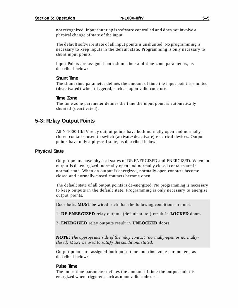
Configurations With Free Egress:
Input Point Reserved for: Default shunt time
Input 1 Door position switch for Door 1 15 secondsInput 2 Door position switch for Door 2 15 secondsInput 3* Door position switch for Door 3 15 secondsInput 4* Door position switch for Door 4 15 seconds
Input 5 Egress device for Door 1 0 seconds (N/A)Input 6 Egress device for Door 2 0 seconds (N/A)Input 7* Egress device for Door 3 0 seconds (N/A)Input 8* Egress device for Door 4 0 seconds (N/A)
Output Point Reserved for: Default pulse time
Output 1 Door lock for Door 1 10 secondsOutput 2 Door lock for Door 2 10 secondsOutput 3* Door lock for Door 3 10 secondsOutput 4* Door lock for Door 4 10 seconds
Input 5 is interlocked to Output 1. An activation of Input 5 (via egress attempt)causes Output 1 to energize for the duration of its pulse time.
Input 6 is interlocked to Output 2. An activation of Input 6 (via egress attempt)causes Output 2 to energize for the duration of its pulse time.
Output 1 is interlocked to Input 1. An activation of Output 1 (such as upon validcode use at card reader/keypad 1 or egress attempt) causes Input 1 to beshunted for the duration of its shunt time.
Output 2 is interlocked to Input 2. An activation of Output 2 (such as upon validcode use at Card Reader/Keypad 2 or egress attempt) causes Input 2 to beshunted for the duration of its shunt time. (See Figure 5-6.)
*N-1000-IV only

Section 5: OperationSection 5: OperationSection 5: OperationSection 5: OperationSection 5: Operation N-1000-III/IV N-1000-III/IV N-1000-III/IV N-1000-III/IV N-1000-III/IV 5–95–95–95–95–9
Figure 5-5 Interlocked Input/Output Points on Door WITH Anti-passback.Example: Valid code use at either card reader (or keypad) triggers the pulse time of OutputRelay 1, unlocking Door 1 for 10 seconds. The activation of Output 1 triggers the shunt time ofInput 1 (via the interlock), shunting Door 1 status switch for 15 seconds.
K 1
K 1
N-1000-III
Card Reader 1 – In
Inpu
t 1
Door Status Switch
Reader 1Reader 1
To N-1000To N-1000
K3K1
Reader 1In
Reader 3In
N-1000-IV
Inpu
t 1
Inpu
t 3
Door 2
Door 1
Reader 2Out
Reader 4Out
DoorStatusSwitch
DoorStatusSwitch
Common
Card Reader 2 – Out
Output Point (relay) 1Pulse Time = 10 seconds
Output Point (relay) 1Pulse Time = 10 seconds
Output Point (relay) 3Pulse Time = 10 seconds
Shunt time =15 sec.
Door 1
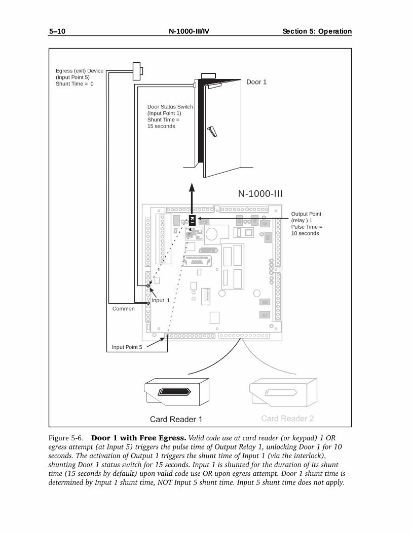
5–105–105–105–105–10 N-1000-III/IVN-1000-III/IVN-1000-III/IVN-1000-III/IVN-1000-III/IV Section 5: OperationSection 5: OperationSection 5: OperationSection 5: OperationSection 5: Operation
Figure 5-6. Door 1 with Free Egress. Valid code use at card reader (or keypad) 1 ORegress attempt (at Input 5) triggers the pulse time of Output Relay 1, unlocking Door 1 for 10seconds. The activation of Output 1 triggers the shunt time of Input 1 (via the interlock),shunting Door 1 status switch for 15 seconds. Input 1 is shunted for the duration of its shunttime (15 seconds by default) upon valid code use OR upon egress attempt. Door 1 shunt time isdetermined by Input 1 shunt time, NOT Input 5 shunt time. Input 5 shunt time does not apply.
Panel must beearth grounded.Panel must be
earth grounded.
S-4 SUPPRESSIONREQUIRED ACROSSEVERY ACTIVE RELAYAND ELECTRICAL
DEVICE (CONNECTWITHIN 18 INCHES).
S-4 SUPPRESSIONREQUIRED ACROSSEVERY ACTIVE RELAYAND ELECTRICAL
DEVICE (CONNECTWITHIN 18 INCHES).
Lock Solenoid
1
3456789
10
2
1112
K 1
K 1
Common
Input 1
N-1000-III
Door Status Switch(Input Point 1)Shunt Time =15 seconds
Egress (exit) Device(Input Point 5)Shunt Time = 0
Input Point 5
Output Point(relay ) 1Pulse Time =10 seconds
Door 1

Section 5: OperationSection 5: OperationSection 5: OperationSection 5: OperationSection 5: Operation N-1000-III/IV N-1000-III/IV N-1000-III/IV N-1000-III/IV N-1000-III/IV 5–115–115–115–115–11
Figure 5-7. Door 2 with Free Egress. Valid code use at Card Reader (or Keypad) 2 ORegress attempt (at Input 6) triggers the pulse time of Output Relay 2, unlocking Door 2 for 10seconds. The activation of Output 2 triggers the shunt time of Input 2 (via the interlock),shunting Door 2 status switch for 15 seconds. Input 2 is shunted for the duration of its shunttime (15 seconds by default) upon valid code use OR upon egress attempt. Door 2 shunt time isdetermined by Input 2 shunt time, NOT Input 6 shunt time. Input 6 shunt time does not apply.
WARNING!
Panel must beearth grounded.Panel must be
earth grounded.
WARNING!
S-4 SUPPRESSIONREQUIRED ACROSSEVERY ACTIVE RELAYAND ELECTRICAL
DEVICE (CONNECTWITHIN 18 INCHES).
S-4 SUPPRESSIONREQUIRED ACROSSEVERY ACTIVE RELAYAND ELECTRICAL
DEVICE (CONNECTWITHIN 18 INCHES).
Lock Solenoid
1
3456789
10
2
1112
Lock Power SupplyLock Power Supply
K3
K4
K 1
K 1
K5
K10 K6
K7
K8
K2
Card Reader 2Card Reader 1Card Reader 1
Common
N-1000-III
Door Status Switch(Input Point 2)Shunt Time =15 seconds
Egress (exit) device(Input Point 6)Shunt Time = 0
Input point 6
Output point(relay ) 2pulse time =10 seconds
Door 2
Input 2

5–125–125–125–125–12 N-1000-III/IVN-1000-III/IVN-1000-III/IVN-1000-III/IVN-1000-III/IV Section 5: OperationSection 5: OperationSection 5: OperationSection 5: OperationSection 5: Operation
Figure 5-8. Door 3 with Free Egress. Valid code use at card reader 3 OR egress attempt(at Input 7) triggers the pulse time of Output Relay 3, unlocking door 3 for 10 seconds. Theactivation of Output 3 triggers the shunt time of Input 3 (via the interlock), shunting door 3status switch for 15 seconds. Input 3 is shunted for the duration of its shunt time (15 seconds bydefault) upon valid code use or egress attempt. Door 3 shunt time is determined by Input 3shunt time, not Input 7 shunt time. Input 7 shunt time does not apply.
Panel must beearth grounded.Panel must be
earth grounded.
S-4 SUPPRESSIONREQUIRED ACROSSEVERY ACTIVE RELAYAND ELECTRICAL
DEVICE (CONNECTWITHIN 18 INCHES).
S-4 SUPPRESSIONREQUIRED ACROSSEVERY ACTIVE RELAYAND ELECTRICAL
DEVICE (CONNECTWITHIN 18 INCHES).
Lock Solenoid
1
3456789
10
2
1112
K 1
K 1
Common
N-1000-IV
Door Status Switch(input Point 3)Shunt Time =15 seconds
Egress (exit) Device(input Point 7)Shunt Time = 0
Input 7
Output Point (relay ) 3Pulse Time = 10 seconds
Door 3
Input 3
ShieldGND+5vDØD1LED
ShieldGND+5vDØD1LED
ShieldGND+5vDØD1LED
ShieldGND+5vDØD1LED
LED D1 DØ +5v GND Shield LED D1 DØ +5v GND Shield
StatusLED
StatusLED Northern Computers, Inc.Northern Computers, Inc.
Reader 1Reader 1 Reader 2Reader 2
Reader 3Reader 3
Reader 4Reader 4
To N-1000To N-1000

Section 5: OperationSection 5: OperationSection 5: OperationSection 5: OperationSection 5: Operation N-1000-III/IV N-1000-III/IV N-1000-III/IV N-1000-III/IV N-1000-III/IV 5–135–135–135–135–13
Figure 5-9. Door 4 with Free Egress. Valid code use at card reader 4 OR egress attempt(at Input 8) triggers the pulse time of Output Relay 4, unlocking door 4 for 10 seconds. Theactivation of Output 4 triggers the shunt time of Input 4 (via the interlock), shunting door 4status switch for 15 seconds. Input 4 is shunted for the duration of its shunt time (15 seconds bydefault) upon valid code use or egress attempt. Door 4 shunt time is determined by Input 4shunt time, not Input 8 shunt time. Input 8 shunt time does not apply.
Panel must beearth grounded.Panel must be
earth grounded.
S-4 SUPPRESSIONREQUIRED ACROSSEVERY ACTIVE RELAYAND ELECTRICAL
DEVICE (CONNECTWITHIN 18 INCHES).
S-4 SUPPRESSIONREQUIRED ACROSSEVERY ACTIVE RELAYAND ELECTRICAL
DEVICE (CONNECTWITHIN 18 INCHES).
Lock Solenoid
1
3456789
10
2
1112
K 1
K 1
Common
N-1000-IV
Door Status Switch(Input Point 4)Shunt Time =15 seconds
Egress (exit) Device(Input Point 8)Shunt Time = 0
Input 8
Output Point (relay ) 4Pulse Time = 10 seconds
Door 4
Input 4
ShieldGND+5vDØD1LED
ShieldGND+5vDØD1LED
ShieldGND+5vDØD1LED
ShieldGND+5vDØD1LED
LED D1 DØ +5v GND Shield LED D1 DØ +5v GND Shield
StatusLED
StatusLED Northern Computers, Inc.Northern Computers, Inc.
Reader 1Reader 1 Reader 2Reader 2
Reader 3Reader 3
Reader 4Reader 4
To N-1000To N-1000

5–145–145–145–145–14 N-1000-III/IVN-1000-III/IVN-1000-III/IVN-1000-III/IVN-1000-III/IV Section 5: OperationSection 5: OperationSection 5: OperationSection 5: OperationSection 5: Operation
5-5: Auto-Relock Operation
The auto-relock feature results in the immediate re-locking and re-arming(unshunting) of a door when the door status switch is closed after entry. Withauto-relock operation, an output relay (controlling a door lock) de-energizeswhen the corresponding Input Point (door status switch) returns to normal state,and the Input Point is re-armed (unshunted) rather than remaining energized(shunted) for the duration of its pulse/shunt time.
Auto-relock associations between inputs and outputs are NOT considered inter-locks and do not appear as interlocks on Input Point reports and output pointreports.
Auto-relock operation can be set manually with the V Command, K option foundin Appendix A.
Default auto-relock operation is described below and illustrated in Figure 5-10,5-11 and 5-12.
With Anti-PassbackWith anti-passback enabled, Input 1 is configured for auto-relock with Output 1.
Without Anti-PassbackWithout anti-passback enabled, Input Point 1 is configured for auto-relock withOutput 1 and Input 2 is configured for auto-relock operation with Output 2.
5-6: Time Zone Controlled Doors
When Time Zone controlling a door (for free access) that is operated by a cardreader or keypad, the Time Zone must be assigned to the relay output point.
Example:
Want to keep Door 1 (controlled by Card Reader 1) unlocked during Time Zone 5,defined as 9 A.M. to 6:30 P.M., Monday through Friday.
Time Zone 5 must be assigned to Output 1 to unlock the door during the timezone.
The default interlock to shunt the door status switch will prevent an alarm fromoccurring while the output is pulse/energized.

Section 5: OperationSection 5: OperationSection 5: OperationSection 5: OperationSection 5: Operation N-1000-III/IV N-1000-III/IV N-1000-III/IV N-1000-III/IV N-1000-III/IV 5–155–155–155–155–15
Figure 5-10. Auto-relock with Anti-Passback. Example: Valid code use at either cardreader (or keypad) triggers the pulse time of Output Relay 1, unlocking Door 1 for 10 seconds.The activation of Output 1 triggers the shunt time of Input 1 (via the interlock), shunting Door1 status switch for 15 seconds. Output Relay 1 de-energizes immediately upon Input 1’s return tonormal state, relocking Door 1 and re-arming Input 1, rather than remaining energized(shunted) for the duration of the 10 second pulse time/15 second shunt time.
WARNING!WARNING!
K3
K4
K5
K10K6
K7
K8
Card Reader 1 Card Reader 2
N-1000-III
Door 1
Door Status Device (Input Point 1)Shunt Time = 15 seconds
Output Point (relay) 1Pulse Time = 10 seconds
K1K1K1
Input 1

5–165–165–165–165–16 N-1000-III/IVN-1000-III/IVN-1000-III/IVN-1000-III/IVN-1000-III/IV Section 5: OperationSection 5: OperationSection 5: OperationSection 5: OperationSection 5: Operation
Figure 5-11. Auto-relock Doors 1 and 2 without Anti-passback. Output Relay 1de-energizes immediately upon Input Point 1’s return to normal state, re-locking Door 1 andre-arming Input 1, rather than remaining energized (shunted) for the duration of the 10 secondpulse time/15 second shunt time. Output Relay 2 de-energizes immediately upon Input Point 2’sreturn to normal state, re-locking Door 2 and re-arming Input 2, rather than remainingenergized (shunted) for the duration of the 10 second pulse time/15 second shunt time.
WARNING!WARNING!
K3
K4
K5
K10K6
K7
K8
Card Reader 1 Card Reader 2
N-1000-III
Door 1
Door 2
Egress (exit) Device (Input Point 6)Shunt Time = 0
Door Status Device(Input Point 2)Shunt Time = 15 seconds
Output point(relay) 1
10 secondsPulse Time =
K2 K1
Egress (exit) Device (Input Point 5)Shunt Time = 0
Door Status Device(input Point 1)Shunt Time =15 seconds
Output Point(relay) 2Pulse Time =10 seconds
K1
K1
K2
K2
Input 2
Input 1
Common
Input 5 Input 6

Section 5: OperationSection 5: OperationSection 5: OperationSection 5: OperationSection 5: Operation N-1000-III/IV N-1000-III/IV N-1000-III/IV N-1000-III/IV N-1000-III/IV 5–175–175–175–175–17
Figure 5-12. Auto-relock Doors 3 and 4 without Anti-passback. Output Relay 3de-energizes immediately upon Input Point 3’s return to normal state, re-locking door 3 andre-arming Input 3, rather than remaining energized (shunted) for the duration of the 10 secondpulse time/15 second shunt time. Output Relay 4 de-energizes immediately upon Input Point 4’sreturn to normal state, re-locking door 4 and re-arming Input 4, rather than remainingenergized (shunted) for the duration of the 10 second pulse time/15 second shunt time.
WARNING!WARNING!
K4
K5
K10K6
ShieldGND+5vDØD1LED
ShieldGND+5vDØD1LED
LED D1 DØ +5v GND Shield LED D1 DØ +5v GND Shieldd
Card Reader 3
Card Reader 4
N-1000-IV
Door 3
Door 4
Egress (Exit) Device (Input Point 8)Shunt Time = 0
Door Status Device(Input Point 4)Shunt Time = 15 seconds
Output point(relay) 4pulse time =10 seconds
K3 K4
Egress (Exit) Device (Input Point 7)Shunt Time = 0
Door Status Device(Input Point 3)Shunt Time = 15 seconds
Output point(relay) 3pulse time =10 seconds
Input 4
Input 3
K3
K3
K4
K4
Input 7
Input 8

5–185–185–185–185–18 N-1000-III/IVN-1000-III/IVN-1000-III/IVN-1000-III/IVN-1000-III/IV Section 5: OperationSection 5: OperationSection 5: OperationSection 5: OperationSection 5: Operation

N-1000-III/IVSection 6: Wiring RequirementsSection 6: Wiring RequirementsSection 6: Wiring RequirementsSection 6: Wiring RequirementsSection 6: Wiring Requirements 6-16-16-16-16-1
Section 6: Wiring Requirements
6-1: Card Readers
Some card readers require that a format (software) command be programmed intothe host N-1000-III/IV controller before cards can be read. When a card is runthrough a card reader that requires a format command, but the format commandhas not been programmed into the control panel, no card number is transmitted tothe terminal/printer. Refer to Appendix A for complete F Command format listings.
N-1000-III Terminal Block 5 supports interface to two Wiegand output card readersand provides an alarm point common. Each card reader port includes terminals forLED control, Data 1 signal, Data Ø signal, +5 VDC output and Ground. See Figure6-1 for typical wiring diagram.*
Card reader/keypad communication shields should be connected to TB5 position12. The shield at the card reader/keypad end should not be grounded unless thedevice is electrically floating (not touching metal). (See Figure 6-1.)
Typical Card Readers using Reader Cable NC1861 or for Plenum applicationsNCP1861 have the following terminations (maximum distance is 500' or 152 m).Refer to documentation included with your reader for the latest information.(Cable specifications and part numbers are listed at the end of this section.)
Reader 1:TerminalBlock Terminal Function Reader Wire Color
5 1 LED (Aux. Output 11) Brown5 2 Data 1 White5 3 Data 0 Green5 (or 9) 4 (or 7) +5 VDC (+12 VDC)* Red5 5 Ground Black
– Not used Blue5 12 Shield
Reader 2:TerminalBlock Terminal Function Reader Wire Color
5 (or 9) 4 (or 7) +5 VDC (+12 VDC)* Red5 5 Ground Black5 6 Data 0 Green5 7 Data 1 White5 8 LED (Aux. Output 12) Brown
– Not used Blue5 12 Shield
*+12 VDC 500 mA power is available on Terminal Block 9 position 7. Use TB5terminal 4 OR TB9 terminal 7 NOT BOTH.

N-1000-III/IV6-26-26-26-26-2 Section 6: Wiring RequirementsSection 6: Wiring RequirementsSection 6: Wiring RequirementsSection 6: Wiring RequirementsSection 6: Wiring Requirements
Figure 6-1. Card Reader Connections to TB5. N-1000-III Terminal Block 5 supportsinterface for two Wiegand output card readers and provides an alarm point common. Each cardreader port includes terminals for LED control, Data 1 signal, Data Ø signal, +5 VDC output andGround. +12 VDC power is available on Terminal Block 9 position 7. Card reader/keypadcommunication shields should be connected to TB5 position 12. The shield at the card reader/keypad end should not be grounded unless the device is electrically floating (not touching metal).
Brown LEDWhite Data 1Green Data ØRed +5 VDCBlack GroundBlue Not used
(Aux. Output 11)
Panel must beearth grounded.
S-4 SUPPRESSIONREQUIRED ACROSSEVERY ACTIVE RELAYAND ELECTRICAL
DEVICE (CONNECTWITHIN 18 INCHES).
Lock Solenoid
1
3456789
10
2
1112
Shield
Shieldno connection
Shield
Shieldno connection
Card Reader 1 Card Reader 2
Blue Not usedRed +5 VDCBlack GroundGreen Data ØWhite Data 1Brown LED
(Aux. Output 12)

N-1000-III/IVSection 6: Wiring RequirementsSection 6: Wiring RequirementsSection 6: Wiring RequirementsSection 6: Wiring RequirementsSection 6: Wiring Requirements 6-36-36-36-36-3
6-2: Four Reader Board (N-1000-IV Only)
The N-1000-IV includes a board that supports up to four card readers. The wiringterminal blocks are removable and interchangeable. No connections should bemade to the TB5 terminals of the main board when the Four Reader Board isconnected. (See Figure 6-2.)
If a reader requires 12 VDC, power can be obtained from TB9 terminal 7. Theelectrical load on TB9 terminal 7 must not exceed 500 mA. If the combined readercurrent draw exceeds 500 mA, a separate power supply should be used. Refer tothe Readers’ Technical Bulletin for the wiring details.
Reader 1, 2, 3, 4:Terminal Function Reader Wire Color
1 LED (Aux. Output 11) Brown2 Data 1 White3 Data Ø Green4 (TB9-7) +5 VDC (+12 VDC)* Red5 Ground Black– Not used Blue
*+12 VDC power is available on Terminal Block 9 terminal 7. Use connection 4 orTB9 terminal 7 NOT BOTH.
Figure 6-2. Card Reader Connections for the N-1000-IV. The N-1000-IV includes aboard that supports up to four card readers. The wiring terminals are removable andinterchangeable. No connections should be made to the TB5 terminals of the main board when theFour Reader Board is connected.
LED Brown(Aux. Output #14)
Data 1 White
Data Ø Green
+ 5 VDC Red
Ground Black
Shield Cable Drain Wire
Typical reader connections.Refer to reader documentationfor the most recentcolor terminations.
ShieldGND+5vDØD1LED
ShieldGND+5vDØD1LED
LED D1 DØ +5v GND Shield LED D1 DØ +5v GND Shield
StatusLED Northern Computers, Inc.
Reader 1 Reader 2
Reader 3
Reader 4
To N-1000
Aux. Output #13
Aux. Output #12Aux. Output #11
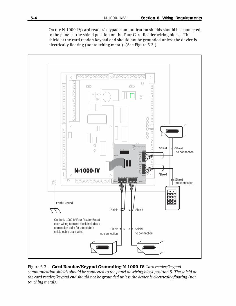
N-1000-III/IV6-46-46-46-46-4 Section 6: Wiring RequirementsSection 6: Wiring RequirementsSection 6: Wiring RequirementsSection 6: Wiring RequirementsSection 6: Wiring Requirements
Figure 6-3. Card Reader/Keypad Grounding N-1000-IV. Card reader/keypadcommunication shields should be connected to the panel at wiring block position 5. The shield atthe card reader/keypad end should not be grounded unless the device is electrically floating (nottouching metal).
On the N-1000-IV, card reader/keypad communication shields should be connectedto the panel at the shield position on the Four Card Reader wiring blocks. Theshield at the card reader/keypad end should not be grounded unless the device iselectrically floating (not touching metal). (See Figure 6-3.)
Earth Ground
ShieldGND+5vDØD1LED
ShieldGND+5vDØD1LED
LED D1 DØ +5v GND Shield LED D1 DØ +5v GND Shield
StatusLED Northern Computers, Inc.
Reader 1 Reader 2
Reader 3
Reader 4
To N-1000
N-1000-IV
On the N-1000-IV Four Reader Boardeach wiring terminal block includes atermination point for the reader'sshield cable drain wire.
Shield Shield
Shield
Shield
Shield
Shield
no connectionShield
no connection
no connection
no connection
Shield
Shield

N-1000-III/IVSection 6: Wiring RequirementsSection 6: Wiring RequirementsSection 6: Wiring RequirementsSection 6: Wiring RequirementsSection 6: Wiring Requirements 6-56-56-56-56-5
6-3: Eleven Conductor Keypads
A typical Eleven Conductor Keypad uses a 2 of 7 matrix configuration where eachkeypad row and column corresponds to a unique wire (Figure 6-4). When a key ispressed, two of seven wires are activated (two of the wires are put to ground); onewire corresponds to the key’s row and one wire corresponds to the key’s column.For example, if the 3 button is pressed, the gray (row 1) and green (column 3)wires are activated (put to ground). If the 8 button is pressed, the yellow (row 3)and blue (column 2) wires are activated (put to ground).
Typical eleven conductor keypads, using Keypad Cable NC18121 or for Plenumapplications NCP18121 (maximum distance is 500' or 152 m), have the followingterminations (See Figure 6-5):
Keypad 1 Keypad 2TB Terminal Wire Color TB Terminal Wire Color8 1 Brown 8 1 Brown8 2 Blue 8 2 Blue8 3 Green 8 3 Green8 4 Black 8 4 Black8 5 Gray 8 5 Gray8 6 Purple 8 6 Purple8 7 Yellow 8 7 Yellow8 8 Orange 8 8 Orange8 9 Peach/Pink 8 9 Peach/Pink8 10 White 8 11 White5 4 Red 5 4 Red
Refer to your keypad technical documentation for the latest information.
Figure 6-4. Eleven Conductor Keypad 2 of 7 Matrix.
1 2 3
4 5 6
7 8 9
* 0 #
Gray(Row 1)
Purple(Row 2)
Yellow(Row 3)
Brown(Col. 1)
Blue(Col. 2)
Green(Col. 3)
Orange(Row 4)
Clears entry
Enters number sequence(1, 2, 3, #) = these items were entered

N-1000-III/IV6-66-66-66-66-6 Section 6: Wiring RequirementsSection 6: Wiring RequirementsSection 6: Wiring RequirementsSection 6: Wiring RequirementsSection 6: Wiring Requirements
Tan Earth Ground wire connections (Not used on all keypads).If the keypad is mounted directly on grounded metal, tie the tan wire to thegrounded metal and tie the keypad cable shield to the N-1000-III/IV groundingpoint (float shield at keypad).
If the keypad is mounted on ungrounded metal or nonmetallic material, tie the tanwire to the keypad cable’s shield only and connect the shield to the N-1000-III/IVground point.
Figure 6-5. Eleven Conductor Keypad Connection to the N-1000-III/IV. If thekeypad is mounted on ungrounded metal or nonmetallic material, tie the tan wire to the keypadcable’s shield only and connect the shield to the N-1000-III/IV ground point.
N-1000-III
Lock Solenoid
Earth Ground
+ 5 V
DC
1 2 3 4
Eleven conductor keypad to N-1000 III/IV useKeypad Cable NC18121 (11 conductor, 18 gaugeshielded cable); Maximum distance: 500' (152 m).
Red wire to TB5 terminal 4(N-1000-IV Red wire to terminal + 5 VDC on any terminal block)
Tan wire
Shield
1 Brown2 Blue3 Green4 Black5 Gray6 Purple7 Yellow8 Orange9 Pink/Peach10 WhiteTB8
TB5

N-1000-III/IVSection 6: Wiring RequirementsSection 6: Wiring RequirementsSection 6: Wiring RequirementsSection 6: Wiring RequirementsSection 6: Wiring Requirements 6-76-76-76-76-7
6-4: Alarm Input Points
Panel/communication cable NC1821/NCP1821 (twisted, 18 gauge overall shieldedcable) is recommended for alarm input point use. This enables the input device tobe located up to 2000 feet (610 m) away from the N-1000-III/IV.
Connect the shield to the panel’s earth ground and leave the other end of the shieldnot connected.
All N-1000-III/IV alarm point commons are electrically the same and can beused with any panel alarm point. Refer to terminal block diagrams in Section 4for alarm point common locations.
If end of line (EOL) resistors are used for supervised inputs, then they must belocated at the switch in order to be effective.
Refer to Appendix A for a summary list of specific alarm input point commands.
6-5: Relay Output Points
Panel/communications cable NC1821/NCP1821 (twisted pair, 18 gauge, overallshielded) is recommended for relay output point use. This enables the outputdevice to be located up to 2000 feet (620 m) away from the N-1000-III/IV. An 18gauge wire’s resistance results in a 6.5 volt drop for a quarter ampere load at 2000feet.
Refer to Appendix A for a summary list of specific relay output point commands.
6-6: Communications
6-6-1: PC to C-100-A1
Cable CBL-2 (three conductor, 18-20 gauge) is recommended for use between thePC and the C-100-A1 Converter. This enables the C-100-A1 to be located up to 50feet (15 m) away from the CPU (See Figure 6-6).
6-6-2: C-100-A1 to Panel(s)
Panel/communications cable NC1821/NCP1821 (twisted pair, 18 gaugeshielded) is recommended, enabling runs of up to 2000 feet (610 m), for each ofthe following:
• C-100-A1 to first panel in communication loop.• Panel to panel.• Last panel in communication loop to C-100-A1. (See Figure 6-6.)
The 20 mA communications loop for the C-100-A1 and the N-1000-III/IV operateusing active-transmit and passive-receive. The Communications Type SelectionJumper JP1 must be set to the 20 mA (default) position 1 & 2.

N-1000-III/IV6-86-86-86-86-8 Section 6: Wiring RequirementsSection 6: Wiring RequirementsSection 6: Wiring RequirementsSection 6: Wiring RequirementsSection 6: Wiring Requirements
Figure 6-6. Typical 20 mA Communication Loop. See Figure 6-10 for AEP-3 connections.
In a single panel 20 mA communication loop, ground the communication cableshield only at the panel, as shown in Figure 6-8.
In a multiple 20 mA panel communication loop, the 20 mA communicationcable shield between any two given panels in the loop should be grounded atone end only. Ground either the receive side or the transmit side of the shield(not both), giving care to be consistent throughout the loop. The receive sidegrounding method is preferred (see Figure 6-9). The transmit side grounding method isnot recommended.
6-6-3: AEP-3 to N-1000-III/IV
Up to two AEP-3 Relay Expansion Boards per N-1000-III/IV panel can be addedto the communication loop. Using the cable supplied with the unit, one AEP-3connects to the N-1000-III/IV at J1, and then to the next AEP-3.(See Figure 6-10.) Refer to the AEP-3 manual for further details.
C-100-A1Maximum 63 control panelsper communication loop.
Controller to controller: twisted pair18 gauge (0.75 mm ) shielded cableMaximum distance: 2000' (610 m)
2
Card readers to N-1000-III/IV: useNC1861 cable (5 conductor, 18 gaugeshielded); Maximum distance: 500' (152 m)
Keypads to N-1000-III/IV: use NC18121cable(11 conductor, 18 gauge shielded cable)Maximum distance: 500' (152 m)
PC com port 1 to C-100-A1: use use CBL-2(3 conductor, 18-20 gauge cable)Maximum distance: 50' (15 m)
Up to two AEP-3 RelayExpansion Boards per panel:4 conductor, 24 gaugeshielded cable.Max. distance: 5 ' (1.1 m)

N-1000-III/IVSection 6: Wiring RequirementsSection 6: Wiring RequirementsSection 6: Wiring RequirementsSection 6: Wiring RequirementsSection 6: Wiring Requirements 6-96-96-96-96-9
Figure 6-7. Typical C-100-A1 Multiple Panel 20 mA Communication Loop. Referto Figure 6-9 for grounding of the communication loop. The Communications Type SelectionJumper JP1 must be set to the 20 mA (default) position 1 & 2.
PPanel must beanel must beearearth grounded.th grounded.
C-100 to N-1000-III/IV:two, NC1821 cablesMaximum distance: 2000' (610 m)
Controller to Controller:two, NC1821 cablesMaximum distance: 2000' (610 m)
N-1000-III/IV
C-100-A1 to PC: CBL-2Maximum distance: 50' (15 m)
Last Controller to C-100:two, NC1821 cablesMaximum distance: 2000' (610 m)
PPanel must beanel must beearearth grounded.th grounded.
PPanel must beanel must beearearth grounded.th grounded.
9 Receive +
10 Receive –
11 Transmit +
12 Transmit –
9 Receive +
10 Receive –
11 Transmit +
12 Transmit –
9 Receive +
10 Receive –
11 Transmit +
12 Transmit –
C-100-A1
Red
White
Black
Grn
White
Green
Red
Blk
Note:The CommunicationsType Selection Jumper JP1must be set to the 20 mA(default) position 1 and 2.
Red
White
Black
Grn

N-1000-III/IV6-106-106-106-106-10 Section 6: Wiring RequirementsSection 6: Wiring RequirementsSection 6: Wiring RequirementsSection 6: Wiring RequirementsSection 6: Wiring Requirements
Figure 6-8. Grounding a Single Panel, 20 mA Communication Loop. In a singlepanel 20 mA communication loop, ground the communication cable shield only at the panel.
Figure 6-9. Grounding a Multiple Panel, 20 mA Communication Loop. In a multiple20 mA panel communication loop, the 20 mA communication cable shield between any two givenpanels in the loop should be grounded at one end only. The preferred receive side groundingmethod is shown here. The transmit side grounding method is not recommended.
Panel must beearth grounded.
S-4 SUPPRESSIONREQUIRED ACROSSEVERY ACTIVE RELAYAND ELECTRICAL
DEVICE (CONNECTWITHIN 18 INCHES).
Lock Solenoid
1
3456789
10
2
1112
Earth Ground N-1000-III/V
Shield ShieldC-100-A1
C-100-A1
Shield
N-1000-III/IV
Earth Ground
Shield
Earth Ground Earth Ground
Shield ShieldShield Shield
Earth Ground
Shield

N-1000-III/IVSection 6: Wiring RequirementsSection 6: Wiring RequirementsSection 6: Wiring RequirementsSection 6: Wiring RequirementsSection 6: Wiring Requirements 6-116-116-116-116-11
Figure 6-10. Connecting an AEP-3 Relay Expansion Board. The AEP-3 Relay ExpansionBoard is shipped with a cable. It connects to the N-1000-III/IV panel at J1. The next AEP-3Expansion Board connects to the first as shown above. See the AEP-3 manual for further details.
AEP-3
(Both AEP-3 Boards aremounted upside down)
N-1000-III/IV
AEP-3 to N-1000-III/IVcable shipped with AEP-3
AEP-3
P2
P1
WhiteBlackRedGreen
J1 AEP-3Rev. A Connector
4321
WhiteBlackRedGreen
P1
4321
4321
N-1000-III/IV6-126-126-126-126-12 Section 6: Wiring RequirementsSection 6: Wiring RequirementsSection 6: Wiring RequirementsSection 6: Wiring RequirementsSection 6: Wiring Requirements
Figure 6-11. Typical N-485 Multi-drop Configuration. This is a typical configurationwith an N-485-PCI-2 at one end of the line and a panel at the other end. The AEP-3 is connected to the N-1000-III/IV at J1. See Figure 6-10 for details of the AEP-3 connection.
6-6-4: PC to N-485-PCI-2
The N-485-PCI-2 uses a 9 pin female connector which will plug into a standard 9pin serial port on the PC. If the PC is configured for use with a serial expansiondevice, an adaptor cable or shell may be required. Refer to the N-485-2 AdapterInstallation Guide (TD1077) for proper configuration. Figure 6-11 shows a typicalconfiguration with an N-485-PCI-2 at one end of the line and a panel at the otherend.
6-6-5: N-485-PCI-2 to Panel
The NC2021/NCP 2021 cable is recommended (twisted pair, 24 gauge overallshielded cable with a characteristic impedance of 120 ohms and a capacitance of20 pf/ft. (or lower) should be used). Consult the device installation guide for cablelengths and configurations.
The Communications Type Selection Jumper JP1 must be set to the RS-485position 2 & 3. For proper communication, jumpers JP2, JP3 and JP4 must alsobe properly configured on each panel. Refer to Section 6-6-8 and Figure 6-13 fordetails.
For 485 multi-drop communications, the shield should be connected at both endsand only to the screw terminals labeled 485 Shield as in Figure 6-14. The shieldshould be tied to the earth ground only at the PCI or HUB.
For a typical configuration using the N485DRLA Digital Redundant Loop Adaptersee Figure 6-15.
485 Dropline up to 31 control panels,using NCP2021-WH-A, NC2021-GY-A.Maximum overall distance 4000' (1220 m)
PCI-2
Personal Computerrunning NCI software
AEP-3
AEP-3

N-1000-III/IVSection 6: Wiring RequirementsSection 6: Wiring RequirementsSection 6: Wiring RequirementsSection 6: Wiring RequirementsSection 6: Wiring Requirements 6-136-136-136-136-13
Note: When mixing N-1000-II panels witú the Núú000-IIúúIV in úú N-485údropline, the N-485-API-2 panels must have the same version (1.xx,2.xx...) as the N-1000-III/IV panel’s 485 EPROM.
The dropline must be terminated at the ends. No other termination should be usedat the panels which are not located at the ends.
For proper configuration of the N-1000-II in mixed loops, refer to the manuals forN-485-API-2, N-485-PCI-2, and N-485-HUB-2.
6-6-6: N-485-HUB-2 to Panel
The same cable should be used as the connection between the N-485-PCI-2 andthe panels. The Communications Type Selection Jumper JP1 must be set to theRS-485 position 2 & 3. Figure 6-12 shows a typical configuration with a HUBusing modems.
6-6-7: N-485-HUB-2 to Modem
The N-485-HUB-2 includes a DB-25 male connector, with a three foot long cable,to plug directly into the modem.
Figure 6-12. Typical N-485 Multi-drop Configuration. This is a typical configurationusing an N-485-HUB-2 and modems and mixed N-1000 panels.
PersonalComputer
M-9600-2Modem
M-9600-2Modem
Control Panelwith N-485-API-2
RS-485 Multi-Drop Line:Up to 31 panels per line
N-485-HUB-2must be at theend of themulti-drop line
3 foot 25 pincable intomodem
Control Panelwith N-485-API-2
N-1000-IV N-1000-III N-1000-II N-1000-II

N-1000-III/IV6-146-146-146-146-14 Section 6: Wiring RequirementsSection 6: Wiring RequirementsSection 6: Wiring RequirementsSection 6: Wiring RequirementsSection 6: Wiring Requirements
6-6-8: Bias and EOL with 485 Communication
Bias voltage, provided by “pull up/down” resistors (bias resistors), is required forthe greatest clarity in 485 transmissions. At least one bias resistor must be con-nected to a given drop line. In addition there must be an end of line resistor (EOL)at both ends of the copper wire on a drop line for units to function efficiently.
Bias and EOL resistors are built into the N-1000-III/IV panel, the PCI, HUB and APIunits. On the PCI and HUB, bias and EOL are present on the line when the green/white wires are attached. With the API, bias and EOL are present when properattachments are made to pins 1 and 2 on TB2 (Refer to TD1077, N-485 Communi-cation Adaptor Installation Guide that comes with the N-485-API-2.)
The N-1000-III/IV can provide bias for the PCI, HUB and API units when they arenot at the end of the line. Bias and EOL resistors on the N-1000-III/IV are attachedby using the proper jumper settings. Setting JP2 and JP3 on provides both bias andEOL, while setting JP4 on provides EOL only. When JP2 and JP3 are on, JP4 mustbe off.
Refer to Figure 6-13 for examples of bias and EOL.
Rule of Thumb for end of line termination (EOL).
1. EOL at both ends of copper.
2. Only one N-1000-III/IV panel, PCI, HUB or API provides 485 line bias. Bias isprovided when the green/white wires are used on the PCI and HUB, whenattachments are made to pins 1 and 2 on TB2 on the API or when JP2 and JP3are used on the N-1000-III/IV panel. JP4 must not be used at the same time asJP2 & JP3.

N-1000-III/IVSection 6: Wiring RequirementsSection 6: Wiring RequirementsSection 6: Wiring RequirementsSection 6: Wiring RequirementsSection 6: Wiring Requirements 6-156-156-156-156-15
Figure 6-13. 485 Multi-drop Bias and EOL If the N-485-PCI-2 (or HUB-2) is wiredbetween two panels and not at the end of the multi-drop communications wiring, terminate thelast panel at one end only with JP 2 and JP 3 inserted and JP 4 off.
PCI-2
Personal Computerrunning NCI software
PCI-2
Personal Computerrunning NCI software
PCI-2
Personal Computerrunning NCI software Fiber modem with
EOL but no Bias
When the PCI is at the end of the drop line, it provides bias and EOLfor the line. The N-1000 at the right provides EOL for the other end.
JP2 & 3 OFF–no bias, no EOLJP4 OFF–no EOL
Green/WhiteConnected–EOL, bias
When the PCI is not at the end of the drop line, JP2 and JP3provide bias and EOL at one end and JP4 provides EOL at the other.
Green/WhiteConnected–no bias, no EOLNot
In this configuration, the PCI provides biasfor the left side, JP2 & JP3 provide it for the right.
Green/WhiteConnected–bias, EOL
JP2 & 3 OFF–no bias, no EOLJP4 OFF–no EOL
JP2 & 3 OFF–no bias, no EOLJP4 ON– EOL
JP2 & 3 ON–bias, EOLJP4 OFF–no EOL
JP2 & 3 OFF–no bias, no EOLJP4 OFF–no EOL
JP2 & 3 OFF–no bias, no EOLJP4 ON– EOL
JP2 & 3 OFF–no bias, no EOLJP4 OFF–no EOL
JP2 & 3 OFF–no bias, no EOLJP4 OFF–no EOL
JP2 & 3 ON– bias, EOLJP4 ON–EOL

N-1000-III/IV6-166-166-166-166-16 Section 6: Wiring RequirementsSection 6: Wiring RequirementsSection 6: Wiring RequirementsSection 6: Wiring RequirementsSection 6: Wiring Requirements
Figure 6-14. 485 Multi-drop Connection with Shielded Cable. A 485 communicationloop with a PCI at the end of the line.
PPanel must beanel must beearearth grounded.th grounded.
N-485 A+
N-485 B –
2
3
Red
Black
Red
Black
N-1000-III/IV
PPanel must beanel must beearearth grounded.th grounded.
PPanel must beanel must beearearth grounded.th grounded.From the N-485-PCI-2 to the N-1000-III/IV
and from the N-1000-III/IV to the N-1000-III/IVuse twisted 24 gauge NC2021-GY-Aor NCP2021-WH-A overall shieldedcable with a characteristic impedanceof 120 ohm and a capacitanceof 20 pf./ft. (or lower)
N-485-PCI-2 to PC:Standard 9 pin femaleconnector plugs into theserial port of the PC
The cable shield shouldbe connected at bothends and only to theTB9 position 12.
N-485-PCI-2
RED wire
REDwire
GREEN wire
BLACKwire
WHITE wire
BLACK wire
to N-1000-III/IV
TB7
TB9
485 cable shield only
12
N-485 A+
N-485 B –
2
3
Red
Black
Red
Black
N-485 A+
N-485 B –
2
3
Red
Black
JP4 OffJP 2 & 3 Off
TB7
TB7
Connect both shieldsbut leave thisconnection floatingDO NOT TIE TO EARTH
BothPins
TB9
485 cable shield only
12
TB9
485 cable shield only
12
The CommunicationsType Selection Jumper JP1must be set to the RS-485position 2 and 3.
used withN-1000-II(Refer to
manualfor details)
N-485CommunicationsAdapter
N-485-API-2
JP4 OffJP 2 & 3 Off
JP4 OnJP 2 & 3 Off
Note:

N-1000-III/IVSection 6: Wiring RequirementsSection 6: Wiring RequirementsSection 6: Wiring RequirementsSection 6: Wiring RequirementsSection 6: Wiring Requirements 6-176-176-176-176-17
Figure 6-15. 485 Multi-drop Connection with N485DRLA. The N-485-DRLA DigitalRedundant Loop Adapter provides an alternate communications route in the event that wiring iscut or a short circuit. Also, the signal is amplified at each node, allowing longer wiring distances. Aminimum of three DRLAs are required.

N-1000-III/IV6-186-186-186-186-18 Section 6: Wiring RequirementsSection 6: Wiring RequirementsSection 6: Wiring RequirementsSection 6: Wiring RequirementsSection 6: Wiring Requirements
6-7: Cable Specifications
Application NCI Part No. AWG Description Max. Dist. Imp. Cap.
CPU to C-100-A1 CBL-2 N/A 9-25 pin adapter 6' (1.8 m)
C-100-A1 to controller, NC1821-GR 18 twisted pair, shielded 2000' (610 m)controller to controller,controller to C-100-A1
N-485 connections NC2021-GY-A N/A twisted pair, shielded 4000' (1200 m) 120 Ω 20pf/ft or NCP2021-WH-A N/A 2 conductor
N-1000-II to AEP-3 5' (1.1 m)
CR-1, TR-1, CI-1, KR-1 NC1861-BL 18 6 conductor shielded 500' (152 m)Wiegand card readers
NR-1 magstripe reader NC1861-BL 18 6 conductor shielded 500' (152 m)
PR-1-280 Cotag reader:280 read head to SZC NC1861-BL 18 6 conductor shielded 300' (91 m)SZC to N-1000-II NC1861-BL 18 6 conductor shielded 500' (152 m)
PR-2 Hughes reader:scanner to reader NC1861-BL 18 6 conductor shielded 30' (9 m)reader to N-1000-II NC1861-BL 18 6 conductor shielded 500' (152 m)
PR-3, PR-5 Indala readers:A-3/A-5 read head to RE-2
NC18121-YL 18 12 conductor shielded 75' (23 m)RE-2 to N-1000-II NC1861-BL 18 6 conductor shielded 500' (152 m)
PR-20 , PR-22Indala readers:A-20/A-22 read headto RE-2 NC18121-YL 18 12 conductor shielded 75' (23 m)RE-2 to N-1000-II NC1861-BL 18 6 conductor shielded 500' (152 m)
PR-10, PR-12 Indalareaders: NC1861-BL 18 6 conductor shielded 500' (152 m)
HG-3 hand geometryreader: NC1861-BL 18 6 conductor shielded 500' (152 m)
11 conductor keypad NC18121-YL 18 12 conductor shielded 500' (152 m)
5 conductor keypad NC1861-BL 18 6 conductor shielded 500' (152 m)
Alarm input points NC1821-GR 18 twisted pair, shielded 2000' (610 m) or NC 2221-BR 22
Relay outputs NC 1821-GR 18 twisted pair, shielded 2000' (610 m) or NC 2221-BR 22 2 conductor
Note: for Plenum rated cable just add a “P” to Northern’s part number prefix

N-1000-III/IVSection 6: Wiring RequirementsSection 6: Wiring RequirementsSection 6: Wiring RequirementsSection 6: Wiring RequirementsSection 6: Wiring Requirements 6-196-196-196-196-19
6-8: NCI Cable Part Numbers
Part Number Description Application Length
NC1821-GR 18 AWG/2 conductor panel/communication cable 1,000'
NC2021-GY-A 24 AWG/2 conductor RS-485 panel/ 1,000'communication cable120 ohm impedance,20 pf/ft capacitance
NC1841-GY 18 AWG/4 conductor reader cable 1,000'
NC1861-BL-500 18 AWG/6 conductor reader cable 500'
NC1861-BL 18 AWG/6 conductor reader cable 1,000'
NC18121-YL-500 18 AWG/12 conductor keypad cable 500'
NC18121-YL 18 AWG/12 conductor keypad cable 1,000'
NCNET-1 50 ohm network cable 1,000'NC2221-BR 22 AWG/2 conductor alarm cable 1,000'
NC1821-OR 18 AWG/2 conductor power/door cable 1,000'
NCC59206-BK RG-59 video cable 1,000'
NCP1821-GR 18 AWG/2 conductor Plenum panel/communication cable 1,000'
NCP2021-WH-A 24 AWG/2 conductor Plenum RS-485 communication cable 1,000'120 ohm impedance,20 pf/ft capacitance
NCP1841-GY 18 AWG/4 conductor Plenum reader cable 1,000'
NCP1861-BL-500 18 AWG/6 conductor Plenum reader cable 500'NCP1861-BL 18AWG/6 conductor Plenum reader cable 1,000'NCP18121-YL 18 AWG/12 conductor Plenum keypad cable 1,000'NCP18121-YL-500 18 AWG/12 conductor Plenum keypad cable 500'
NCPNET-1 50 ohm Plenum network cable 1,000'NCP2221-BR 22 AWG/2 conductor Plenum alarm point cable 1,000'
NCP1821-OR 8 AWG/2 conductor Plenum power/door cable 1,000'
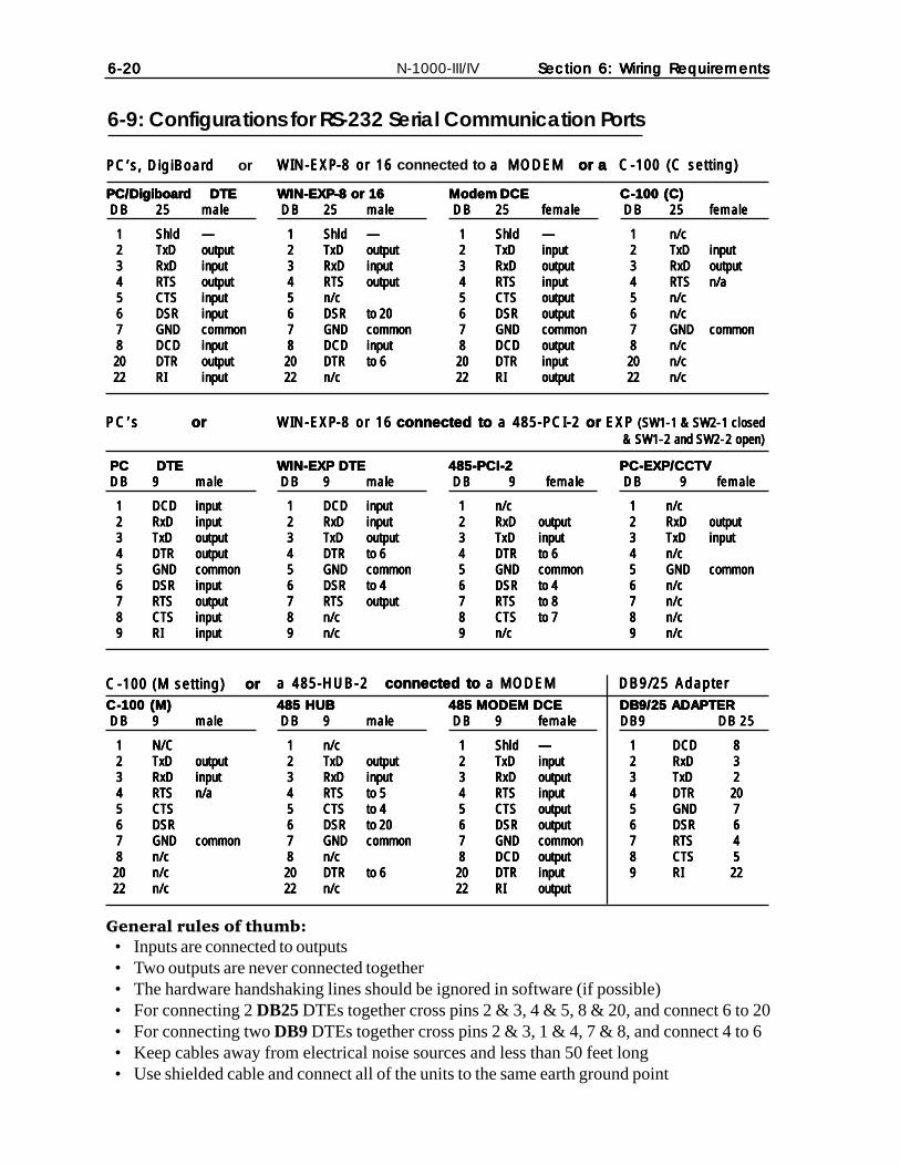
N-1000-III/IV6-206-206-206-206-20 Section 6: Wiring RequirementsSection 6: Wiring RequirementsSection 6: Wiring RequirementsSection 6: Wiring RequirementsSection 6: Wiring Requirements
6-9: Configurations for RS-232 Serial Communication Ports
General rules of thumb:• Inputs are connected to outputs• Two outputs are never connected together• The hardware handshaking lines should be ignored in software (if possible)• For connecting 2 DB25 DTEs together cross pins 2 & 3, 4 & 5, 8 & 20, and connect 6 to 20• For connecting two DB9 DTEs together cross pins 2 & 3, 1 & 4, 7 & 8, and connect 4 to 6• Keep cables away from electrical noise sources and less than 50 feet long• Use shielded cable and connect all of the units to the same earth ground point
PC/DigiboardPC/DigiboardPC/DigiboardPC/DigiboardPC/Digiboard DTEDTEDTEDTEDTEDBDBDBDBDB 2525252525 malemalemalemalemale
11111 ShldShldShldShldShld —————22222 TxDTxDTxDTxDTxD outputoutputoutputoutputoutput33333 RxDRxDRxDRxDRxD inputinputinputinputinput44444 RTSRTSRTSRTSRTS outputoutputoutputoutputoutput55555 CTSCTSCTSCTSCTS inputinputinputinputinput66666 DSRDSRDSRDSRDSR inputinputinputinputinput77777 GNDGNDGNDGNDGND commoncommoncommoncommoncommon88888 DCDDCDDCDDCDDCD inputinputinputinputinput2020202020 DTRDTRDTRDTRDTR outputoutputoutputoutputoutput2222222222 RIRIRIRIRI inputinputinputinputinput
WIN-EXPWIN-EXPWIN-EXPWIN-EXPWIN-EXP-8 or 16-8 or 16-8 or 16-8 or 16-8 or 16 connected to a MODEM a MODEM a MODEM a MODEM a MODEM or a or a or a or a or a CCCCC-100 (C setting)-100 (C setting)-100 (C setting)-100 (C setting)-100 (C setting)
WIN-EXPWIN-EXPWIN-EXPWIN-EXPWIN-EXP-8 or 16-8 or 16-8 or 16-8 or 16-8 or 16DBDBDBDBDB 2525252525 malemalemalemalemale
11111 ShldShldShldShldShld —————22222 TxDTxDTxDTxDTxD outputoutputoutputoutputoutput33333 RxDRxDRxDRxDRxD inputinputinputinputinput44444 RTSRTSRTSRTSRTS outputoutputoutputoutputoutput55555 n/cn/cn/cn/cn/c66666 DSRDSRDSRDSRDSR to 20to 20to 20to 20to 2077777 GNDGNDGNDGNDGND commoncommoncommoncommoncommon88888 DCDDCDDCDDCDDCD inputinputinputinputinput
2020202020 DTRDTRDTRDTRDTR to 6to 6to 6to 6to 62222222222 n/cn/cn/cn/cn/c
Modem DCEModem DCEModem DCEModem DCEModem DCEDBDBDBDBDB 2525252525 femalefemalefemalefemalefemale
11111 ShldShldShldShldShld —————22222 TxDTxDTxDTxDTxD inputinputinputinputinput33333 RxDRxDRxDRxDRxD outputoutputoutputoutputoutput44444 RTSRTSRTSRTSRTS inputinputinputinputinput55555 CTSCTSCTSCTSCTS outputoutputoutputoutputoutput66666 DSRDSRDSRDSRDSR outputoutputoutputoutputoutput77777 GNDGNDGNDGNDGND commoncommoncommoncommoncommon88888 DCDDCDDCDDCDDCD outputoutputoutputoutputoutput
2020202020 DTRDTRDTRDTRDTR inputinputinputinputinput2222222222 RIRIRIRIRI outputoutputoutputoutputoutput
PC’s, DigiBoard PC’s, DigiBoard PC’s, DigiBoard PC’s, DigiBoard PC’s, DigiBoard or
CCCCC-100 (C)-100 (C)-100 (C)-100 (C)-100 (C)DBDBDBDBDB 2525252525 femalefemalefemalefemalefemale
11111 n/cn/cn/cn/cn/c22222 TxDTxDTxDTxDTxD inputinputinputinputinput33333 RxDRxDRxDRxDRxD outputoutputoutputoutputoutput44444 RTSRTSRTSRTSRTS n/an/an/an/an/a55555 n/cn/cn/cn/cn/c66666 n/cn/cn/cn/cn/c77777 GNDGNDGNDGNDGND commoncommoncommoncommoncommon88888 n/cn/cn/cn/cn/c2020202020 n/cn/cn/cn/cn/c2222222222 n/cn/cn/cn/cn/c
PCPCPCPCPC DTEDTEDTEDTEDTEDBDBDBDBDB 99999 malemalemalemalemale
11111 DCDDCDDCDDCDDCD inputinputinputinputinput22222 RxDRxDRxDRxDRxD inputinputinputinputinput33333 TxDTxDTxDTxDTxD outputoutputoutputoutputoutput44444 DTRDTRDTRDTRDTR outputoutputoutputoutputoutput55555 GNDGNDGNDGNDGND commoncommoncommoncommoncommon66666 DSRDSRDSRDSRDSR inputinputinputinputinput77777 RTSRTSRTSRTSRTS outputoutputoutputoutputoutput88888 CTSCTSCTSCTSCTS inputinputinputinputinput99999 RIRIRIRIRI inputinputinputinputinput
WIN-EXPWIN-EXPWIN-EXPWIN-EXPWIN-EXP-8 or 16-8 or 16-8 or 16-8 or 16-8 or 16 connected toconnected toconnected toconnected toconnected to a 485-PCI-2 a 485-PCI-2 a 485-PCI-2 a 485-PCI-2 a 485-PCI-2 ororororor EXP EXP EXP EXP EXP (SW1-1 & SW2-1 closed(SW1-1 & SW2-1 closed(SW1-1 & SW2-1 closed(SW1-1 & SW2-1 closed(SW1-1 & SW2-1 closed & SW1-2 and SW2-2 open) & SW1-2 and SW2-2 open) & SW1-2 and SW2-2 open) & SW1-2 and SW2-2 open) & SW1-2 and SW2-2 open)
WIN-EXP DTEWIN-EXP DTEWIN-EXP DTEWIN-EXP DTEWIN-EXP DTEDBDBDBDBDB 99999 malemalemalemalemale
11111 DCDDCDDCDDCDDCD inputinputinputinputinput22222 RxDRxDRxDRxDRxD inputinputinputinputinput33333 TxDTxDTxDTxDTxD outputoutputoutputoutputoutput44444 DTRDTRDTRDTRDTR to 6to 6to 6to 6to 655555 GNDGNDGNDGNDGND commoncommoncommoncommoncommon66666 DSRDSRDSRDSRDSR to 4to 4to 4to 4to 477777 RTSRTSRTSRTSRTS outputoutputoutputoutputoutput88888 n/cn/cn/cn/cn/c99999 n/cn/cn/cn/cn/c
485-PCI-2485-PCI-2485-PCI-2485-PCI-2485-PCI-2DBDBDBDBDB 99999 femalefemalefemalefemalefemale
11111 n/cn/cn/cn/cn/c22222 RxDRxDRxDRxDRxD outputoutputoutputoutputoutput33333 TxDTxDTxDTxDTxD inputinputinputinputinput44444 DTRDTRDTRDTRDTR to 6to 6to 6to 6to 655555 GNDGNDGNDGNDGND commoncommoncommoncommoncommon66666 DSRDSRDSRDSRDSR to 4to 4to 4to 4to 477777 RTSRTSRTSRTSRTS to 8to 8to 8to 8to 888888 CTSCTSCTSCTSCTS to 7to 7to 7to 7to 799999 n/cn/cn/cn/cn/c
PC’sPC’sPC’sPC’sPC’s or or or or or
PCPCPCPCPC-EXP/CCTV-EXP/CCTV-EXP/CCTV-EXP/CCTV-EXP/CCTVDBDBDBDBDB 99999 femalefemalefemalefemalefemale
11111 n/cn/cn/cn/cn/c22222 RxDRxDRxDRxDRxD outputoutputoutputoutputoutput33333 TxDTxDTxDTxDTxD inputinputinputinputinput44444 n/cn/cn/cn/cn/c55555 GNDGNDGNDGNDGND commoncommoncommoncommoncommon66666 n/cn/cn/cn/cn/c77777 n/cn/cn/cn/cn/c88888 n/cn/cn/cn/cn/c99999 n/cn/cn/cn/cn/c
CCCCC-100 (M)-100 (M)-100 (M)-100 (M)-100 (M)DBDBDBDBDB 99999 malemalemalemalemale
11111 N/CN/CN/CN/CN/C22222 TxDTxDTxDTxDTxD outputoutputoutputoutputoutput33333 RxDRxDRxDRxDRxD inputinputinputinputinput44444 RTSRTSRTSRTSRTS n/an/an/an/an/a55555 CTSCTSCTSCTSCTS66666 DSRDSRDSRDSRDSR77777 GNDGNDGNDGNDGND commoncommoncommoncommoncommon88888 n/cn/cn/cn/cn/c
2020202020 n/cn/cn/cn/cn/c2222222222 n/cn/cn/cn/cn/c
a 485-HUBa 485-HUBa 485-HUBa 485-HUBa 485-HUB-2-2-2-2-2 connected toconnected toconnected toconnected toconnected to a MODEM a MODEM a MODEM a MODEM a MODEM485 HUB485 HUB485 HUB485 HUB485 HUBDBDBDBDBDB 99999 malemalemalemalemale
11111 n/cn/cn/cn/cn/c22222 TxDTxDTxDTxDTxD outputoutputoutputoutputoutput33333 RxDRxDRxDRxDRxD inputinputinputinputinput44444 RTSRTSRTSRTSRTS to 5to 5to 5to 5to 555555 CTSCTSCTSCTSCTS to 4to 4to 4to 4to 466666 DSRDSRDSRDSRDSR to 20to 20to 20to 20to 2077777 GNDGNDGNDGNDGND commoncommoncommoncommoncommon88888 n/cn/cn/cn/cn/c2020202020 DTRDTRDTRDTRDTR to 6to 6to 6to 6to 62222222222 n/cn/cn/cn/cn/c
485 MODEM DCE485 MODEM DCE485 MODEM DCE485 MODEM DCE485 MODEM DCEDBDBDBDBDB 99999 femalefemalefemalefemalefemale
11111 ShldShldShldShldShld —————22222 TxDTxDTxDTxDTxD inputinputinputinputinput33333 RxDRxDRxDRxDRxD outputoutputoutputoutputoutput44444 RTSRTSRTSRTSRTS inputinputinputinputinput55555 CTSCTSCTSCTSCTS outputoutputoutputoutputoutput66666 DSRDSRDSRDSRDSR outputoutputoutputoutputoutput77777 GNDGNDGNDGNDGND commoncommoncommoncommoncommon88888 DCDDCDDCDDCDDCD outputoutputoutputoutputoutput
2020202020 DTRDTRDTRDTRDTR inputinputinputinputinput2222222222 RIRIRIRIRI outputoutputoutputoutputoutput
CCCCC-100 (M setting) -100 (M setting) -100 (M setting) -100 (M setting) -100 (M setting) or or or or orDB9/25 ADAPTERDB9/25 ADAPTERDB9/25 ADAPTERDB9/25 ADAPTERDB9/25 ADAPTERDB9DB9DB9DB9DB9 DB 25DB 25DB 25DB 25DB 25
11111 DCDDCDDCDDCDDCD 8888822222 RxDRxDRxDRxDRxD 3333333333 TxDTxDTxDTxDTxD 2222244444 DTRDTRDTRDTRDTR 202020202055555 GNDGNDGNDGNDGND 7777766666 DSRDSRDSRDSRDSR 6666677777 RTSRTSRTSRTSRTS 4444488888 CTSCTSCTSCTSCTS 5555599999 RIRIRIRIRI 2222222222
DB9/25 AdapterDB9/25 AdapterDB9/25 AdapterDB9/25 AdapterDB9/25 Adapter

Section 7: Locks and Suppression N-1000-III/IVN-1000-III/IVN-1000-III/IVN-1000-III/IVN-1000-III/IV 7–1
Section 7: Locks and Suppression
An S-4 Suppressor Kit must be installed with every electrical switching device runthrough a relay contact on the N-1000-III/IV. The Suppressor Kit protects theN1000-III/IV from the power generated by the collapsing magnetic field of anelectrical load device.
The S-4 Suppressor Kit consists of two identical pieces. Each piece contains aresistor, a capacitor and tranzorb network. These parts are encapsulated in arubber-like insulating material. One piece is installed across the relay contactswithout regard to polarity. The second is installed within 18 inches (457 mm) ofthe electrical load locking device, without regard to polarity. (See Figure 7-1.)
DO NOT run the panel wires or the lock power wires in the same cable/conduit asthe reader/communication line cables. The lock wiring should be at least 12 inchesaway from the data lines, or it should have a separate conduit.
DO NOT power door locks with the same power supply used for the N-1000-III/IVor card readers.
Figure 7-1. S-4 Suppressor Kit Installation.

7–2 N-1000-III/IVN-1000-III/IVN-1000-III/IVN-1000-III/IVN-1000-III/IV Section 7: Locks and Suppression

Section 8: GroundingSection 8: GroundingSection 8: GroundingSection 8: GroundingSection 8: Grounding 8–1 8–1 8–1 8–1 8–1N-1000-III/IV
Section 8: Grounding
It is important to ground all N-1000-III/IV control panels properly. Each panel inthe communication loop should be individually grounded.
In some locations, the individual earth ground is not adequate and a separate12-14 gauge Common Ground wire should be run along with the communicationloop wire. Ground this wire at one location for the entire system. The 18 gauge orlarger cable must be connected from the panel ground point directly to earthground. The grounding point is shown in Figure 8-1.
Note: The X-4 transformer’s earth ground (TB9–1, refer to Section 4-7) may beused if an unsuitable earth ground exists. The transformer’s 3rd ground prong mustbe plugged into the outlet.
Figure 8-1. Access Control System with Grounding Point.NOTE: The X-4 transformer’s earth ground (TB9–1, see Section 4-7) may be used if an unsuitableearth ground exists. The 3rd ground prong must be plugged into the outlet.Use one or the other, DO NOT USE BOTH TB9-1 and the “local” chassis ground.The chassis earth ground is preferred.
Panel must beearth grounded.
S-4 SUPPRESSIONREQUIRED ACROSSEVERY ACTIVE RELAYAND ELECTRICAL
DEVICE (CONNECTWITHIN 18 INCHES).
Lock Solenoid
1
3456789
10
2
1112
ShieldGND+5vDØD1LED
ShieldGND+5vDØD1LED
LED D1 DØ +5v GND Shield LED D1 DØ +5v GND Shield
StatusLED Northern Computers, Inc.
Reader 1 Reader 2
Reader 3
Reader 4
To N-1000
Grounding Point
Earth Ground

8–28–28–28–28–2 N-1000-III/IV Section 8: GroundingSection 8: GroundingSection 8: GroundingSection 8: GroundingSection 8: GroundingN-1000-III/IV
Figure 8-2 Access Control System with Consolidated Earth Ground.
Use one or the other, DO NOT USE BOTH TB9-1 and the “local” chassis ground.The chassis earth ground is preferred.
In installations where there is a significant amount of electrical noise, shieldsshould be grounded outside of the panel.
The access control system should use a consolidated earth ground, in which thepower line, telephone and access control system ground rods are bonded together.A consolidated earth ground eliminates the problem of step voltage blowout, inwhich measurable voltage potential exists between earth ground rods, resulting ina current flow path and damage to the access control system during a lightningstrike.
Ground wire runs should be as short and straight as possible. Avoid sharp turns anduse a minimum radius of eight inches (203 mm) for bends. Ground wires should berun separate from other wires and be routed toward the earth. Do not run groundwires parallel to metal without proper bonding to the metal. Use of eight foot(2.4 m) copper clad ground rods is recommended. Consolidated earth groundconfiguration is shown in figure 8-2.
TelephoneEarth Ground
Access Control SystemEarth Ground
Power LineEarth Ground

Section 9: PowerSection 9: PowerSection 9: PowerSection 9: PowerSection 9: Power 9–1 9–1 9–1 9–1 9–1N-1000-III/IV
Section 9: Power
The N-1000-III/IV requires a 16.5 VAC, 50 VA, 60 HZ or a 12 VDC linear (2 Ampcontinuous) primary power supply. If using an AC power source as primary powersupply, connect the primary power supply to TB9 positions 4 and 5, without regardto polarity. If using a DC power source as primary power, connect the primarypower supply to TB9 positions 2 and 3, noting polarity. Use one or the other forprimary power supply, not both. N-1000-III/IV AC power terminals are shown infigure 9-1.
Upon loss of primary power, the control panel is powered from the 12 VDC(4 amp/hour) backup battery, if present, for up to four hours of full operation.Alarm point #19 goes into alarm state upon primary power loss. Battery wires withfast-on connectors are soldered to the N-1000-III/IV panel. Use these to connectthe 12 VDC battery to the panel, with regard to polarity (Figure 9-1).
Figure 9-1 AC, Optional External DC and Backup Power Connections.AC, Optional External DC and Backup Power Connections.AC, Optional External DC and Backup Power Connections.AC, Optional External DC and Backup Power Connections.AC, Optional External DC and Backup Power Connections.

9–29–29–29–29–2 Section 9: PowerSection 9: PowerSection 9: PowerSection 9: PowerSection 9: PowerN-1000-III/IV
For backup function with 12 VDC power, select a 12 VDC power supply withbattery backup capability and/or use the standard 12 VDC backup battery providedwith the control panel. If the external power supply has a relay contact outputwhich indicates a power failure, then it should be wired to TB9–10 and TB9–11.Jumper JP6 (Power Fail Signal) must be moved to Position 1 and 2 in order toenable the external input.
Upon loss of backup battery power, the control panel ceases operation, but retainsdatabase/transaction buffer memory for up to 7 days.
Power-up Sequence for the N-1000-III/IV:Step 1: Set DIP-switch and verify jumper settings.Step 2: Make primary power supply connections.Step 3: Make backup battery connections.
Power-down Sequence for the N-1000-III/IV:Step 1: Remove backup battery connections.Step 2: Remove primary power supply connections.

Appendix A: Quick Reference Guide N-1000-III/IVN-1000-III/IVN-1000-III/IVN-1000-III/IVN-1000-III/IV A–1
Appendix A: Programming Quick Reference Guide
PrefacePrefacePrefacePrefacePreface
The following Programming Guide applies to the N-1000-II and the N-1000-III/IVpanels. The text indicates where there are differences between the N-1000-IIand the N-1000-III/IV. These panels can be programmed using Northern’saccess control software installed on a PC. Information on time zones, areas, panelvariables and access levels can be managed automatically using this software.
These operations can also be performed via terminal or printer/programmer. ThisProgramming Guide provides basic code format information necessary to programthe N-1000-II and N-1000-III/IV control panels. For completeexplanations and examples, contact the factory.
Note: If the N-1000-II or the N-1000-III/IV is to be used in an existingN-1000-II system, the N-1000-II must be at least version 7.0 panel firmware.
Notation ConventionsNotation ConventionsNotation ConventionsNotation ConventionsNotation Conventions
The following notation conventions are used:
bold Literal elements of a command that must be entered exactly asshown.
italic Variables that must be defined by the user. Descriptions of thesevariables follow this section
_ (underscore) A space
<CR> The ENTER key (Carriage Return)
[ ] Brackets surround optional command elements.
Braces surround two or more choices
| A vertical bar separates individual choices within the braces:choice 1 | choice 2 | choice 3. The user must select only oneof the choices.
Invalid Code Error MessagesInvalid Code Error MessagesInvalid Code Error MessagesInvalid Code Error MessagesInvalid Code Error Messages
Error Message Violation
AP Anti-passback violation.
EX Code expired (Limited Use or Visitor status)
NF Code not found (programmed) in memory for theselected card reader or keypad.
TR Trace message (enabled with the C Sub-command 1/Toption). Access is allowed.

A–2 N-1000-III/IVN-1000-III/IVN-1000-III/IVN-1000-III/IVN-1000-III/IV Appendix A: Quick Reference Guide
TZ Time Zone violation.
PN PIN number violation.
SC Site Code violation.
User Defined PUser Defined PUser Defined PUser Defined PUser Defined Parameter Varameter Varameter Varameter Varameter Variablesariablesariablesariablesariables
Parameter User Response
code card number or keycode (1–65535)* OR card number orkeycode range. In a card number or keycode range,specify the first and last codes in the range, separated bya hyphen (-).
code1 first code in a range (1–65535)*
code2 last code in a range (1–65535)*
cc the number of characters to use in the access codenumber (F Command, Sub-Command 5)
dev device number, as shown below:
(N-1000-II) (N-1000-III/IV)
1=card reader 1 1=card reader 1
2=card reader 2 2=card reader 2
3=keypad 1 3=card reader 3
4=keypad 2 4=card reader 4
5=keypad 1
6=keypad 2
day(s) day of week, as shown below:1=Monday2=Tuesday3=Wednesday4=Thursday5=Friday6=Saturday7=Sunday0=Holiday notation (all holidays)
dd day of month (1–31)
deb debounce time (1–255) in seconds
desc descriptive name up to 12 characters
* Value rangeWith the OL Option it is a 10 digit number where the value range of the1st 5 digits is 1-65535; and the 2nd 5 digits is 1-65535With the OJ Option it is an 11 digit number where the value range of the 1st 4digits is 1-4095; and the next 7 digits is 1-1,048,575With the Y Option it is a 16 digit number with a range of 1- 9,999,999,999,999,999
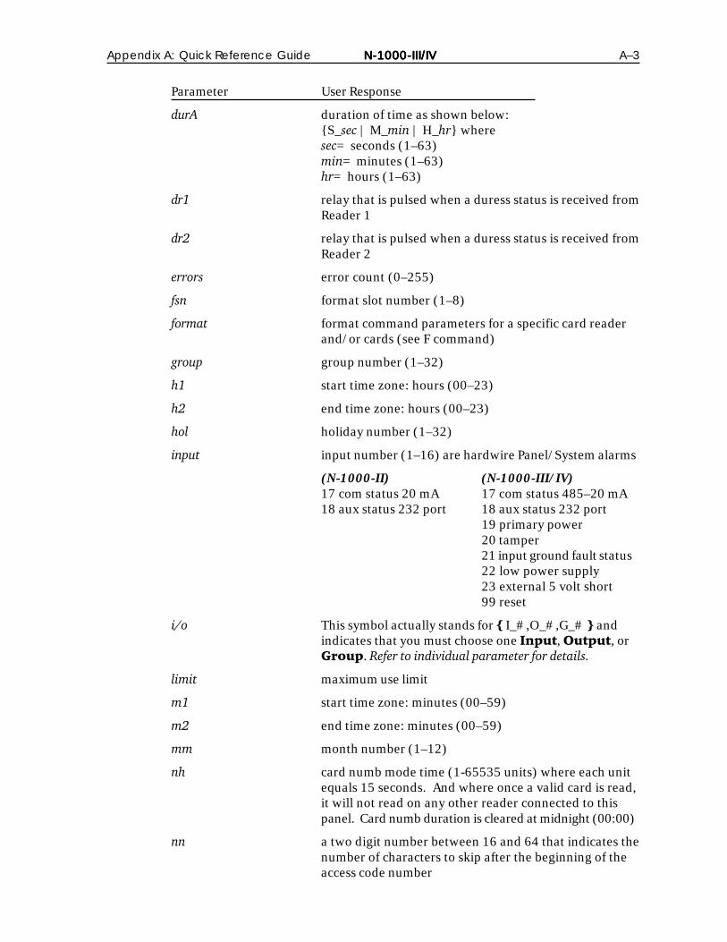
Appendix A: Quick Reference Guide N-1000-III/IVN-1000-III/IVN-1000-III/IVN-1000-III/IVN-1000-III/IV A–3
Parameter User Response
durA duration of time as shown below:S_sec | M_min | H_hr wheresec= seconds (1–63)min= minutes (1–63)hr= hours (1–63)
dr1 relay that is pulsed when a duress status is received fromReader 1
dr2 relay that is pulsed when a duress status is received fromReader 2
errors error count (0–255)
fsn format slot number (1–8)
format format command parameters for a specific card readerand/or cards (see F command)
group group number (1–32)
h1 start time zone: hours (00–23)
h2 end time zone: hours (00–23)
hol holiday number (1–32)
input input number (1–16) are hardwire Panel/System alarms
(N-1000-II) (N-1000-III/IV)17 com status 20 mA 17 com status 485–20 mA18 aux status 232 port 18 aux status 232 port
19 primary power20 tamper21 input ground fault status22 low power supply23 external 5 volt short99 reset
i/o This symbol actually stands for I_#,O_#,G_# andindicates that you must choose one Input, Output, orGroup. Refer to individual parameter for details.
limit maximum use limit
m1 start time zone: minutes (00–59)
m2 end time zone: minutes (00–59)
mm month number (1–12)
nh card numb mode time (1-65535 units) where each unitequals 15 seconds. And where once a valid card is read,it will not read on any other reader connected to thispanel. Card numb duration is cleared at midnight (00:00)
nn a two digit number between 16 and 64 that indicates thenumber of characters to skip after the beginning of theaccess code number

A–4 N-1000-III/IVN-1000-III/IVN-1000-III/IVN-1000-III/IVN-1000-III/IV Appendix A: Quick Reference Guide
Parameter User Response
output output number
(N-1000-II)N-1000 (1–4, 13, 14)N-1000-X (1–8, 13, 14)1st AEP-3 (17–24) 13 = rdr 1 LED2nd AEP-3 (25–32) 14 = rdr 2 LED
(N-1000-III/IV)N-1000 (1–4, 11, 12, 13, 14) 11 = rdr 1 LEDN-1000-X (1–8, 11, 12, 13, 14) 12 = rdr 2 LED1st AEP-3 (17–24) 13 = rdr 3 LED2nd AEP-3 (25–32) 14 = rdr 4 LED
pn panel number (0–63); Ø=global command
relock component to relock as shown below:I_input | O_output | G_group See input, output, andgroup.
shunt time shunt time as shown below:S_sec | M_min | H_hr wheresec= seconds (1–63)min= minutes (1–63)hr= hours (1–63)
sss card site code(s) (0–65535)
tz time zone number (0–63)
tz link time zone link number
# delay count 1–255 (255 = 6 seconds delay)
zgn input group number 1–16
Error CodesError CodesError CodesError CodesError Codes
C? Command Structure Error
F? Database Full Error
R? Range Error
S? Syntax Error
T? Timeout Error
U? Unable to Complete Error

Appendix A: Quick Reference Guide N-1000-III/IVN-1000-III/IVN-1000-III/IVN-1000-III/IVN-1000-III/IV A–5
Programming OrderProgramming OrderProgramming OrderProgramming OrderProgramming Order
The following command list serves as a general guideline for the chronologicalorder of programming.
Command General Purpose
I Clear panel memory
I Initialize panel
T Set time
D Set date
F Set format commands
N Assign descriptive names
L Define time zones
H Set holidays
G Define groups
P Set interlocks
V Assign input/output/group information
O Assign input/output/group information
C Add codes (cards/keycodes)
M Set buffer/print options
E Eliminates pin/invalid attempt counting
A Assigns reader to pulse output/input/groups
W Defines alarm input type (NO, NC, & supervision)
Z Creates groups of Inputs (zones)
CommandsCommandsCommandsCommandsCommands
The following commands are listed in alphabetical order
A CommandA CommandA CommandA CommandA Command
Sub-Sub-Sub-Sub-Sub-Command 1Command 1Command 1Command 1Command 1
Function: Assign reading devices (card readers/keypads) to activate specifiedinput points, output points and groups.
Syntax: _A=pn_dev_i/o_<CR>
Example: _A=1_2_I_5
A valid code use at Card Reader 2 (Device 2) on Panel 1 shunts Input 5for the duration of the input’s set shunt time.

A–6 N-1000-III/IVN-1000-III/IVN-1000-III/IVN-1000-III/IVN-1000-III/IV Appendix A: Quick Reference Guide
Sub-Sub-Sub-Sub-Sub-Command 2Command 2Command 2Command 2Command 2
Function: Set the device from which a PIN is expected for a given card reader.Eliminates required PIN use at specified card reader.
Syntax: _A=pn_dev_D_Ø_dev<CR> (first dev = card reader,second dev = keypad)
Example: _A=1_2_D_Ø
A PIN is not required for access at Card Reader 2 (Device 2) on Panel 1.(This is the most common use of this command.)
C CommandC CommandC CommandC CommandC Command
Sub-Sub-Sub-Sub-Sub-Command 1Command 1Command 1Command 1Command 1
Function: Add a single or multiple codes to memory with special options.
Syntax: _C=pn_code_tz_dev [_i/o][_A][_K][_L_#][_P_#][_T][_N_desc]<CR>
Useroptions: A: Set Anti-passback feature to “IN” (card added with “IN” status.)
(NOTE: the default status of cards is “Unused”)
K: No PIN required
L_#: Limited code use
P: Personal Identification Number (PIN)
T: Trace code
N: Name (must not be used with access control software)
Example: _C=1_594_1_1_2_A_P_12345
Card number 594 is valid with PIN 12345 during Time Zone 1 at bothcard reader/keypad 1 and card reader/keypad 2 (devices 1 and 2) onpanel 1.
Sub-Sub-Sub-Sub-Sub-Command 2Command 2Command 2Command 2Command 2
Function: Allow cards to have different time zones per reader or keypad on asingle panel. Panel must be initialized with I Command, Z_Ø option.
Syntax:
N-1000-II _C=pn_card#_tz1_tz2_dev1/dev3_dev2/dev4<CR>
or
N-1000-III/IV _C=pn_card#_tz1_tz2_tz3_tz4_dev1/dev5_dev2/dev6_dev3_dev4<CR>
Example: _C=1_750_1_3_1_2
Card number 750 is valid at panel during Time Zone 1 on Reader 1 andTime Zone 3 on Reader 2.

Appendix A: Quick Reference Guide N-1000-III/IVN-1000-III/IVN-1000-III/IVN-1000-III/IVN-1000-III/IV A–7
Sub-Sub-Sub-Sub-Sub-Command 3Command 3Command 3Command 3Command 3
Function: Deletes single or multiple code(s) from memory.
Syntax: _C=pn_code<CR> or _C=pn_code1-code2_Ø<CR>
Example: _C=1_25Ø-299_Ø
Codes 250-299 are deleted from memory in panel 1.
Sub-Sub-Sub-Sub-Sub-Command 4Command 4Command 4Command 4Command 4
Function: Generate code database reports based on user-selected parameters.
Syntax: _C=pn_L_limit | N | R | U | Z_tz [_code]<CR>
Useroptions:
L: Limited Use/Visitor status specification
N: IN status
R: Full report
U: OUT status
Z: time zone specification
Example: _C=1_L_3_1ØØØ-12ØØ
The returned report includes only those codes from 1000 to 1200 withthree or fewer uses remaining in Panel 1.
Sub-Sub-Sub-Sub-Sub-Command 5Command 5Command 5Command 5Command 5
Function: Manually set anti-passback IN/OUT code status.
Syntax: _C=pn_I | O_card #<CR>
Useroptions:
I: Set IN status
O: Set OUT status
Example: Reset code
Cardholder 750 enters the building in the morning via the In reader (onPanel 1, Device 1) and exits without using the Out reader (Panel 1,Device 2) in the evening. The following morning, the cardholder isdenied access at the In reader (anti-passback violation).
The system operator enters the following command to set the status ofCard 750 to OUT:_C=1_O_75Ø
Card 750 is then allowed entry at the In reader.

A–8 N-1000-III/IVN-1000-III/IVN-1000-III/IVN-1000-III/IVN-1000-III/IV Appendix A: Quick Reference Guide
Sub-Sub-Sub-Sub-Sub-Command 6Command 6Command 6Command 6Command 6
Function: Allow information in a split time zone card record to be modifiedwithout overwriting the whole command.
Syntax: _C=pn_T_card#_tz_tz_dev <CR>*
_C=pn_C_card#_DeviceList<CR>
UserOptions: T: Reset time zones
C: Delete devices from the card without removing it from the panel
Example: _C=1_T_750_3_5_1
Card 750 already exists in panel but is valid during Time Zones 1 & 6.Now it changes Card 750 to be valid during Time Zone 3 and 5 at device1.
Example: _C=1_C_22939_3_4
Card 22939 had access to devices 1 through 4 at panel 1. Card 22939now only has access at devices 1 and 2 at Panel 1.
*If Ø is entered for the 1st or 2nd Time Zone (or both) it will not overwrite theexisting Time Zone. If a device is listed it will be added to the existing device list.
Sub-Sub-Sub-Sub-Sub-Command 7Command 7Command 7Command 7Command 7
Function: Immediately set the status of all cards to “Out.” Used with panels pro-grammed for Anti-passback.
Syntax: _C=pn_F<CR>
Example: _C=1_F<CR>
All cards in Panel 1 are set to “Out” status.
D CommandD CommandD CommandD CommandD Command
Function: Set control panel date.
Syntax: _D=pn_mm/dd_day <CR>
Example: _D=Ø_2/6_3
The date is set for Wednesday, February 6 in all panels.
Leap Year
Syntax: _D=pn_2/29_Day of week 1-7
Syntax: _D=pn_mm/dd_dow_[yyyy]<CR>
Note: The date command has the option of adding a four digit year after theday of the week. If no year is specified, the panel will assume it is not aleap year, and February 29th will be skipped.

Appendix A: Quick Reference Guide N-1000-III/IVN-1000-III/IVN-1000-III/IVN-1000-III/IVN-1000-III/IV A–9
E CommandE CommandE CommandE CommandE Command
Sub-Sub-Sub-Sub-Sub-Command 1Command 1Command 1Command 1Command 1
Function: Establish the time zones for required use of PINs at specified panels.(Note: Panel must also be initialized with the P option.)
Syntax: _E=pn_P_tz <CR>
Example: _E=1_P_2
During Time Zone 2, a valid card/PIN combination is required for accessin Panel 1. Outside of Time Zone 2, only a valid card is required foraccess.
Sub-Sub-Sub-Sub-Sub-Command 2Command 2Command 2Command 2Command 2
Function: Pulse input point, output point or group, based on a selected number ofconsecutive invalid code uses.
Syntax: _E=pn_C_errors_[R_device #]I_input | O_output | G_group<CR>
Example: _E=1_C_3_R_3_O_3<CR>
Upon three consecutive invalid code uses at Device 3, on Panel 1,Output 3 is pulsed.

A–10 N-1000-III/IVN-1000-III/IVN-1000-III/IVN-1000-III/IVN-1000-III/IV Appendix A: Quick Reference Guide
F CommandF CommandF CommandF CommandF Command
Sub-Sub-Sub-Sub-Sub-Command 1Command 1Command 1Command 1Command 1
Function: Sets the method of interpreting card read data for Wiegand type cards.
Syntax: _F=pn_fsn_format<CR>
Useroptions: CR-1 Wiegand Card Swipe Reader: _F=pn_1_26_S_1_D_1_B1_B2_B3_B4
CI-1 Wiegand Card Insert Reader: _F=pn_1_26_I_S_1_D_1_B1_B2_B3_B4
NR-1 Magstripe Swipe Reader: _F=pn_fsn_32_S_Ø_D_Ø_B1_B2_B3_B4
PR-1-280 Cotag Proximity Reader: _F=pn_fsn_32_S_Ø_D_Ø_B1_B2_B3_B4
PR-2 Hughes/IDI Proximity Reader: _F=pn_fsn_34_S_1_D_1_B1_B2_B3_B4
HG-1 Hand Geometry Reader: _F=pn_fsn_32_S_Ø_D_Ø_B1_B2_B3_B4
5-Conductor Keypad: _F=pn_fsn_32_S_Ø_D_Ø_B1_B2_B3_B4
Dorado Magstripe Cards: _F=pn_fsn_34_S_1_D_Ø_B1_B2_B3_B4
Sielox Wiegand Cards: _F=pn_fsn_34_S_1_D_1_B1_B2_B3_B4
Sielox Proximity Cards: _F=pn_fsn_32_S_Ø_D_Ø_B1_B2_B3_B4
NCS 25-Bit Cards: _F=pn_fsn_25_S_1_D_1_B1_B4_B2_B3
NCS 29-Bit Cards: _F=pn_fsn_29_S_1_D_1_B1_B4_B2_B3
Kidde Cards: _F=pn_fsn_31_S_1_BØ_B2_B3_B4
Continental 36-Bit Cards: _F=pn_fsn_36_S_3_D_2_B1_B2_B3_B4
Continental 37-Bit Cards: _F=pn_fsn_37_S_3_D_2_B1_B2_B3_B4
Example: _F=1_2_32_S_O_D_Ø_B1_B2_B3_B4
The format command entered (as format #2) enables use of CotagProximity Readers in Panel 1.

Appendix A: Quick Reference Guide N-1000-III/IVN-1000-III/IVN-1000-III/IVN-1000-III/IVN-1000-III/IV A–11
Sub-Sub-Sub-Sub-Sub-Command 2Command 2Command 2Command 2Command 2
Function: Sets the format for use with ABA encoded cards—12 digits are usedwith PC-PAK and WIN-PAK.
Syntax: _F=pn_M[_R]_positions 1–12<CR>
Useroption R: Allows debugging of raw card number information.
Example: _F=1_M_Ø_Ø_Ø_Ø_Ø_Ø_1_2_3_4_5_6<CR>
The number indicates the digit number from the card. The position ofthe number in the format indicates where the digit will appear in thefinal mapped card number. A zero in the format will cause a zero toappear at that point in the final card read.
Note: User Option R can be used as shown here when adding toexisting information or with position specified as a separate command.
Sub-Sub-Sub-Sub-Sub-Command 3Command 3Command 3Command 3Command 3
Function: Set the format for 35 bit cards used with the I Command, OJ Option.
Syntax: _F=pn4_35_S_1_D_2_B1_B2_B3_B4<CR>
Sub-Sub-Sub-Sub-Sub-Command 4Command 4Command 4Command 4Command 4
Function: Set the format for use with 29 bit format cards (TI/Silicon Systems)with the I Command, OL Option.
Syntax: _F=pn_fsn_29_S_1_1_B0_B4_B2_B3<CR>
Sub-Sub-Sub-Sub-Sub-Command 5Command 5Command 5Command 5Command 5
Function: Sets the format to support Track 1 Readers, for use with theM400-NORT1 reader.
T: Track 1 reader.
Syntax: _F=pn_M_T_nn_cc<CR>

A–12 N-1000-III/IVN-1000-III/IVN-1000-III/IVN-1000-III/IVN-1000-III/IV Appendix A: Quick Reference Guide
G CommandG CommandG CommandG CommandG Command
Function: Define output point groups.
Syntax: _G=pn[_Z_input]_group_outputs[_W_wgroup]<CR>
Example: _G=1_1_5_6_7_8
Group 1 is defined as outputs 5, 6, 7 and 8 in Panel 1.
Useroptions: W: Warning group
Z: Special output groups
Note: All warning groups must be on the N-1000 panel NOT the AEP-3 board.
Syntax: _G=pn_group_W_wgroup__Outputs<CR>
Example: _G=1_1_W_2_1_1_2<CR>
Creates Group 1 on Panel 1. Group 1 has relays 1 and 2 and uses Group2 as a warning group. (Group 2 must be created and given a pulsetime.)
Syntax: _G=pn_Z_input_group_outputs<CR>
(When the group is used singly the input number functions only tosignify that the group is Special and will follow the rules below. In thecase where only one group is used this should be Ø in order to preventaction being transferred to the next group);
The single Special Group has one main function: It will not go on duringits time zone unless a card is swiped to turn it on. But it will go offautomatically at the end of its time zone in the normal manner. Thismeans, for example, if your front door is on a time zone and there is asnow storm preventing personnel from getting to the office, the doorwill not unlock.
Example: _G=pn_Z_Ø_2_3_4<CR>
Group 2 containing relays 3 and 4 is established. A time zone can thenbe attached to Group 2 via the V Command. When the time zonebegins, nothing happens. When a card valid for Group 2 is used,relays 3 and 4 go on. Subsequent reads during the time zone togglerelays 3 and 4 off or on. If they are on when the time zone ends, they gooff.

Appendix A: Quick Reference Guide N-1000-III/IVN-1000-III/IVN-1000-III/IVN-1000-III/IVN-1000-III/IV A–13
H CommandH CommandH CommandH CommandH Command
Function: Set holiday dates.
Syntax: _H=pn_hol_mm/dd<CR>
Deleting Holidays:
To delete an existing holiday database entry, enter the H Command forthe desired holiday number WITHOUT the month (mm) and day (dd)parameters.
Example: _H=Ø_1_12/25
Holiday 1 is set as December 25 in all panels.
I CommandI CommandI CommandI CommandI Command
Function: Initialize the control panel, enabling features and programming optionsfor future use and set panel site code(s).
Syntax: _I=pn[_sss][_A][_B][_E][_F][_G][_H_nh][_K][_I][_L][_M][_N][_OA]_OD_dr1|_dr2[_OJ][_OL][_ON][_OP_19_S|_OP_Ø][_P][_R][_S][_U][_V][_Y][_Z_Ø] [_Z_tzn]<CR>
Useroptions: A: Anti-passback
B: Continuous code reads (busy)
E: Free egress
F: Forgiveness (with anti-passback)
G: Groups
H: Numb mode "nh" is unit of 15 seconds
K: Keypads
I: In/Out command sent from panel
L: Limited Use Cards
M: Card Reader LED function reversed
N: Names
OA: Alarms are reported when coming out of time zone shunt
OD: Duress option (N-1000-II only) requires card/keypad configura-tion. PIN numbers entered where the last digit is off by 1 (+/-)will cause "dr1" duress relay for Reader 1 or "dr2" duress relayfor Reader 2 to pulse (can be same duress relay). For example,if the normal PIN number is 12345, entering number 12346 or12344 will create a duress condition.
OJ: Format for 35 bit card numbers, the first 12 bits (after thestarter bits) are interpreted as the site code and the next 20 as

A–14 N-1000-III/IVN-1000-III/IVN-1000-III/IVN-1000-III/IVN-1000-III/IV Appendix A: Quick Reference Guide
the card number, followed by 1 stop bit. The resulting site codeand card number are concantenated to form one card number,which is sent to the head end software as a 12-digit number.NOTE: A special format is requires. Refer to F Command,Sub-Command 3.
Application Note: For simplicity of system management, it isrecommended that you set the site code value to Ø when theOJ Option is used.
OL: Create Wiegand card numbers by concantenating site code withcard number. The result is transmitted as a 12 digit number.
ON: Normals are reported when coming out of time zone shunt
OP: Switches the Power Fail Input from Input Point 8 to Input Point19 (_OP_19 _S) or from Input Point 19 to Input Point 8(_OP_Ø). NOTE: Redirecting the Power Fail to Input 19 reclaimsInput 8 as a normal input on the AEP-5 board only. However, thischange will disable the AEP-5 Board Present/Functioning alarm.
P: Personal identification numbers (PIN)
R: Restart
S: Supervisory Board (Not for use with N-1000-III/IV)
U: The number of cards panel should set itself for
V: Visitor cards
Y: Long format ABA cards
Z_Ø: Split time zone
Z_tzn: All cards with time zone numbers higher than the numberindicated will use the next higher time zone at Reader 2. AtReader 1 they will use the time zone attached to the card num-ber.
Global SpecificationControl panels MUST be initialized on an individual basis. The global specification(pn=Ø) is NOT allowed with the I command.
L CommandL CommandL CommandL CommandL Command
Function: Define time zones.
Syntax: _L=pn_tz_h1:m1-h2:m2_days [tz link]<CR>
Comment: Time zone definition consists of a reference number, start time, endtime, day(s) of week specification and optional link number. The endperiod of a time zone goes until the last second of the last minute (e.g.,8:00-17:00–at 17:01 the door is locked).
A time zone definition alone causes no action. Time zones must beassigned to cards/keycodes, input points or output points to causeaction.

Appendix A: Quick Reference Guide N-1000-III/IVN-1000-III/IVN-1000-III/IVN-1000-III/IVN-1000-III/IV A–15
Example: _L=Ø_1_ØØ:ØØ-23:59_1_2_3_4_5_6_7_Ø
Desired time zone: 24 hours every day, including holidays.
M CommandM CommandM CommandM CommandM Command
Sub-Sub-Sub-Sub-Sub-Command 1Command 1Command 1Command 1Command 1
Function: Sets control panel buffer/print options.
Syntax: _M=pn[_P][_D][_L][_V][_X][_F][_R]<CR>
Useroptions: P: The panel buffers all activity.
D: The panel does not buffer or print valid code activity
L: The panel buffers and prints all activity
V: The panel buffers only valid code activity and prints invalid codesand alarm input point activity.
X: The panel buffers all activity and prints invalid codes and alarminput point activity
F: The panel “dumps” the buffer when it is within 100 transactions ofcapacity
R: The buffer is dumped, all buffer/transmit options are cleared
Example: _M=1_P
Panel 1 buffers all activity and transmits no activity.
Sub-Sub-Sub-Sub-Sub-Command 2Command 2Command 2Command 2Command 2
Function: Set control panel anti-passback and “print names” mode of operation.
Syntax: _M=pn_A | N | B | E | K | G<CR>
Useroptions: A: Enable anti-passback
N: Disable anti-passback
B: Disable names
E: Print names
Example: _M=1_N

A–16 N-1000-III/IVN-1000-III/IVN-1000-III/IVN-1000-III/IVN-1000-III/IV Appendix A: Quick Reference Guide
Panel 1 is operating in the anti-passback mode.
Result: Panel 1 is taken out of the anti-passback mode.
Sub-Sub-Sub-Sub-Sub-Command 3Command 3Command 3Command 3Command 3
Function: Disables global “OK” message.
Syntax: _M=Ø_K <CR>
Sub-Sub-Sub-Sub-Sub-Command #4Command #4Command #4Command #4Command #4
Function: Time delay between transmissions.
Syntax: _M=pn_# delay count<CR>
Default: delay count = 1
Maximum = 255 at 6 seconds between transactions.
N CommandN CommandN CommandN CommandN Command
Sub-Sub-Sub-Sub-Sub-Command 1Command 1Command 1Command 1Command 1
Function: Assigns 12 character descriptive names to codes (cards and keycodes).
Syntax: _N=pn_C_code_desc <CR>
Example: _N=1_C_8562_JONES,_MIKE
Code 8562 is assigned the name JONES, MIKE in Panel 1.
Sub-Sub-Sub-Sub-Sub-Command 2Command 2Command 2Command 2Command 2
Function: Assigns 12 character descriptive names to control panels, card readersand keypads.
Syntax: _N=pn_R_dev_desc <CR>
Example: _N=1_R_Ø_LOBBY_PANEL
Control Panel 1 is assigned the name “LOBBY PANEL”
Example: _N=1_R_6_BACK_KEYPAD
Keypad 2 (N-1000-IV) is assigned the name “BACK KEYPAD”
Sub-Sub-Sub-Sub-Sub-Command 3Command 3Command 3Command 3Command 3
Function: Assigns 12 character descriptive names to input points, output pointsand groups.
Syntax: _N=pn_i /o_desc <CR>
Example: _N=1_I_6_BACK DOOR CT
Assigns the name BACK DOOR CT to Input 6 on Panel 1.

Appendix A: Quick Reference Guide N-1000-III/IVN-1000-III/IVN-1000-III/IVN-1000-III/IVN-1000-III/IV A–17
O CommandO CommandO CommandO CommandO Command
Sub-Sub-Sub-Sub-Sub-Command 1Command 1Command 1Command 1Command 1
Function: Provides manual control and sets special options for input points, outputpoints and groups.
Syntax: _O=pn_i /o_A | C | D | E | I | P | O | T | Z <CR>
Useroptions: A: Acknowledge alarm
C: Clear all options
D: De-energize/Unshunt
E: Energize/Shunt
I: Interlock disable
P: Pulse/Shunt (Definable Duration)
O: Keep on
T: Returns a point to its time zone when removed by the O command with the D or E option.
Z: time zone control disable
Example: Group 3 (outputs 1, 3, 5, 7) in Panel 60 is de-energized and assigned a12 second pulse time.
Command: _O=6Ø_G_3_P
Result: Group 3 (outputs 1, 3, 5, 7) pulses for 12 seconds.
Sub-Sub-Sub-Sub-Sub-Command 2Command 2Command 2Command 2Command 2
Function: Used to control input point groups (Zones) which are created using theZ Command.
Syntax: _O=pn_Z_zgn_E<CR>
or
_O=pn_Z_zgn_D<D>

A–18 N-1000-III/IVN-1000-III/IVN-1000-III/IVN-1000-III/IVN-1000-III/IV Appendix A: Quick Reference Guide
P CommandP CommandP CommandP CommandP Command
Function: Sets interlocks between alarm input points and/or output points.
Syntax: _P=pn_i /o1_i /o2_D|E|F|I|N|P|S_D|E|F|I|N|P|S<CR>
Useroptions: D: De-energize
E: Energize
F: Follow
I: Invert follow
N: No action
P: Pulse
S: Pulse off
Example: i/o1: Input 5 (motion detector)
i/o2: Output 3 (siren)
Action 1: Energize
Action 2: De-energize
Interlock command: _P=1_I_5_O_3_E_D
Result: When Input 5 goes into alarm state (motion detector triggered),Output 3 energizes (sounding the alarm). When Input 5 returns tonormal state, Output 3 de-energizes (turning off the siren).
R CommandR CommandR CommandR CommandR Command
Function: Generates control panel database reports which are displayed on thesystem monitor and/or printer.
Syntax: _R=pn_C | G | H | I | O | o | P | p | T | V |Z <CR>
Reportoptions: C: Code (card/keycode) database
G: Groups
H: Holiday schedule
I: Initialization parameters
O: Output points
o: Short output points report
P: Input points
p: Short input points report
T: time zones
V: Firmware version
Z: Z Groups

Appendix A: Quick Reference Guide N-1000-III/IVN-1000-III/IVN-1000-III/IVN-1000-III/IVN-1000-III/IV A–19
T CommandT CommandT CommandT CommandT Command
Function: Sets control panel time.
Syntax: _T=pn_hh:mm <CR>
Example: _T=Ø_17:45
The time is set to 5:45 P.M. in all panels.
V CommandV CommandV CommandV CommandV Command
Sub-Sub-Sub-Sub-Sub-Command 1Command 1Command 1Command 1Command 1
Function: Assigns shunt times and time zones to input points WITH special options.
Syntax: _V=pn_I_input_shunt time_tz[_1][_A_durA[_tzA]][_B[_tzB]][_C][_D_deb][_K_relock][_S[_tzS]][_X][_N_name][_Y[_tzY]]<CR>
Useroptions: 1: Disable alarm/normal messages, but transmit trouble messages
A: Acknowledge required
B: Buffered mode activation
C: Clear options
D: Debounce
K: Enable auto-relock
S: Disable alarm/normal messages
X: Reverse alarm/normal states
N: Name input point
Y: Disabling response to interlock by time zone
Example: Alarm Acknowledge message without time zone
Input 5 (motion detector) monitors a secure area. You want the inputto be shunted (de-activated) during Time zone 20 for free access. Inputshunt time is not applicable. You want alarm acknowledge messageactivation.
Command: _V=1_I_5_Ø_2Ø_A_1Ø
Result: Input 5 is shunted during Time Zone 20 and is assigned a shunttime of 0 (not applicable). When Input 5 goes into alarm condition, analarm acknowledge message is sent to the system monitor and/orprinter. The message is transmitted every 10 seconds until acknowledgedwith the following command: _O=1_I_5_A

A–20 N-1000-III/IVN-1000-III/IVN-1000-III/IVN-1000-III/IVN-1000-III/IV Appendix A: Quick Reference Guide
Sub-Sub-Sub-Sub-Sub-Command 2Command 2Command 2Command 2Command 2
Function: Assign pulse times and time zones to output points WITH specialoptions.
Syntax: _V=pn_O_output_pulse time_tz[_C][_L][_Y_tzY][_N_name]<CR>
Useroptions: C: Clear options
L: Latch
N: Name output point
Y: Disabling response to interlock by time zone
Example: _V=1_O_4_8_Ø_N_FRONT_SIREN
Output Point 4 is not time zone controlled and is assigned a pulse timeof eight seconds. The output is assigned the name “FRONT SIREN.”
Sub-Sub-Sub-Sub-Sub-Command 3Command 3Command 3Command 3Command 3
Function: Assign pulse times and time zones to groups WITH special options.
Syntax: _V=pn_G_group_pulse time_tz [_Y_tzY]_N_name <CR>
User options:
N: Name group
Y: Time zone control interlock
Example: _V=1_G_5_6_Ø_N_ALL_RELAYS
Group 5 is not time zone controlled and is assigned a pulse time of sixseconds. The group is assigned the name “ALL RELAYS.”
W Command (Used with the N-1000-III/IV only)W Command (Used with the N-1000-III/IV only)W Command (Used with the N-1000-III/IV only)W Command (Used with the N-1000-III/IV only)W Command (Used with the N-1000-III/IV only)
Function: Program each input point for either NO/NC and Supervised orNON-Supervised operation.
Syntax: _W=pn_ input_SO|SC|NO|NC<CR>
SO: Supervised normally open (Resistor in parallel with switch);
SC: Supervised normally closed (Resistor in series with switch);
NO: Non-supervised normally open; and
NC: Non-supervised normally closed (default).
If an EOL resistor is put on a point, and it is not set up as a super-vised point (using one of the commands above), it will reportTROUBLE whenever the resistance is connected. This should serve asa warning that the point has not been set up.
Example: _W=1_9_SO<CR>
Alarm Input 9 has been programmed as supervised, normally openon Panel 1.

Appendix A: Quick Reference Guide N-1000-III/IVN-1000-III/IVN-1000-III/IVN-1000-III/IVN-1000-III/IV A–21
Z CommandZ CommandZ CommandZ CommandZ Command
Function: Creates groups of inputs (Zones). Allows shunting of multiple inputs.One command can shunt all required points on the panel rather thanone command for each point. Commands are similar to the G command.
Creation: Z=pn_zgn_input_input etc.
zgn: The number of the group being created (up to 16 of these groups can be created)
input: The input number included in the group.
Control: Through O commands with energize and de-energize such as:_O=pn_Z_zgn_E<CR>
or
_O=pn_Z_zgn_D<D>
OR’ing of InputsOR’ing of InputsOR’ing of InputsOR’ing of InputsOR’ing of Inputs
If two or more inputs are interlocked to a single output to energize on alarm andde-energize on normal, both/all inputs must be normal before the interlock willallow the relay to de-energize.
1. This E (Energize) action will allow situations where, for example, several inputpoints can be interlocked to one relay which is driving a sounder, visual alert ordigital dialer. When several inputs go into alarm and remain in alarm all atonce, the relay will not be turned off after one of them goes back to normal.Rather all inputs must go back to normal before the output will be turned off.
2. The above operation is standard. An alternate method, where one input returningto normal would de-energize the relay, is offered as an option through theuse of a terminal or text command. The command is written with a G designationin place of the E for energize.
Example: _P=pn_I_input_O_on_G_D<CR>

A–22 N-1000-III/IVN-1000-III/IVN-1000-III/IVN-1000-III/IVN-1000-III/IV Appendix A: Quick Reference Guide
Output Groups by ReadersOutput Groups by ReadersOutput Groups by ReadersOutput Groups by ReadersOutput Groups by Readers
This feature allows a card to be used to activate one group when it is used atReader 1 and a different group if it is used at Reader 2.
1. Initialization must include the E Option and the G designation with a numberfollowing it. The number following the G will tell the panel that groups with anumber higher than this number are to be used in the split method. If thenumber is EVEN, the jump described below will be 1. If the number is ODD, thejump will be 2. The ODD/EVEN distinction is used to distinguish the situation ofregular groups, described here, from that of Paired Special Groups.
2. In setting up the groups and assigning them with access levels, it is necessary tokeep in mind that group numbers higher than the number specified in the Icommand will be incremented by 1 when the card is used at Reader 2. (If thenumber above was EVEN. If the number above was ODD it will be incrementedby 2.) The original group number will be used at Reader 1.
Example: _I=pn_E_G_4<CR>
_C=pn_444_1_1_2_G_3<CR>
_C=pn_555_1_1_2_G_7<CR>
Card 444 will pulse group 3 on either reader but card 555 will pulseGroup 7 on Reader 1 and Group 8 on Reader 2.

Appendix B: New FeaturesAppendix B: New FeaturesAppendix B: New FeaturesAppendix B: New FeaturesAppendix B: New Features B–1–1–1–1–1N-1000-III/IV
Appendix B: N-1000-III/IV Compared to N-1000-II
Miscellaneous and Special Items
• Four layer PWB and other improvements provide greater electrical noiseimmunity.
• High efficiency switching regulators result in reduced heat generation andextended backup battery operation.
• The Four Reader Board on the N-1000-IV allows the panel to support a total offour readers. (See Section 4-3 for details.) This board mounts in the lower rightquadrant of the board, and when it is present all 4 readers attach to it viaits removable terminal strips. The regular reader terminals on the main boardare not used when the Four Reader Board is used. The connector for this boardis P3, located directly above the bottom center of the board. The Four ReaderBoard has its own run LED described in the LED section below. It is controlledby a special, programmable chip, called a PIC chip. The paper label on the PICchip indicates a version number similar to the label on the PROM chips on themain board.
• A Reader Function Test is available on the N-1000-IV. A pair of jumper prongslocated on the Four Reader Board and labeled TEST can be shorted to cause afunction test . It will cause the board to generate a simulated card read fromeach of the four readers.
• An improved canister has more knockouts, a larger battery bracket and im-proved wiring space, since the board is centered in the enclosure. (The oldenclosure can be field retrofitted for the new board.)
• The processor speed of 9.8304 mHz is four times faster than standardN-1000-II. This increases the speed of internal processing. The communicationsoutput is the same as the N-1000-II panels so they can be used in the same loop.
• An additional Terminal Block (TB9) has been added in the upper left quadrantof the board. This terminal block has an Earth Ground connection; a batteryplus and minus (in addition to the soldered in battery wires.); AC connections1 and 2 (there are no spade lugs for AC or battery); the Tamper and ExternalPower Fail inputs with common terminals; and a place to tie the 485 shield if itis used.
Memory
• One memory chip is soldered to the panel and a socket is provided for another.The X boards come with two chips.

B–2B–2B–2B–2B–2 Appendix B: New N-FeaturesAppendix B: New N-FeaturesAppendix B: New N-FeaturesAppendix B: New N-FeaturesAppendix B: New N-FeaturesN-1000-III/IV
Communication
• There are both RS- 485 and RS-232 communications ports in addition tothe 20 milliamp port. The 485 port is selected by a change of Jumper 1 in lieuof the 20 milliamp. The RS-232 port can be used in addition to or in lieu ofthe other ports.
• The N-485-API-2 components are now on board the N-1000-III/IV paneleliminating the need for the separate API board. An isolated communicationsinterface is used which is more immune to poor grounding. The terminals usedare TB7 terminals 2 (+) and 3(-). Back-up of the 485 memory is also providedby the “super-cap.”
• There is an onboard 9 pin RS-232 connector to allow a direct hookup to theAUX Port. The components for the AUX Port are on all N-1000-III/IV boards,and the firmware is programmed to use it. This allows trouble shootingcommunication to an individual panel with a computer or terminal while thepanel is still connected to the loop.
Power
• The panel sits in standby mode if there is not enough voltage for reliableoperation upon power up.
• The red primary power fail light flashes rapidly on reset or power-up if thebattery is too low for reliable operation.
• A 16.5 volt AC power source is now required, allowing the charging of a 12 voltbattery for back-up as well as the supply of 12 Volt Reader and PIR egresspower from the N-1000-III/IV.
• A 12 volt output 500 mA is available for powering 12 volt readers or PIRegress detectors. Connections for this are at TB9 terminals 7 (+) and8 (Common).
• Connections are provided for optional 12 volt DC at TB9 terminals 2 and 3.This is a change from the N-1000-II where the 12 volt DC was connected tothe AC terminals.
• Circuitry has been added to detect the drop-out and restoration voltageconditions when the panel is running from the power to the battery terminals.The processor is programmed to respond to both conditions. If the voltage onthese terminals drops to its predefined level, the processor shuts the paneldown. When the voltage rises to the predetermined level, the panel returnsto operation. The voltage for drop out is higher (in the 10 Volt range) than itis for the N-1000-II (in the 9 Volt range).
• Battery Back Up Detector now detects switch-over on an external powersupply (e.g., the PS1-12). In addition to detecting the switch-over fromPrimary Power to battery on the panel itself (as the N-1000-II always has) thenew panel can sense if there is a switch over on an outside power source,such as the PS1-12, without the use of a relay on the outside power source.

Appendix B: New FeaturesAppendix B: New FeaturesAppendix B: New FeaturesAppendix B: New FeaturesAppendix B: New Features B–3–3–3–3–3N-1000-III/IV
• A special input is provided for wiring from power supplies that have aprimary power fail signal. If this input point is used rather than the internalsensor described above, it must be selected by means of jumper JP-6.(1-2 = External and 2-3 = Internal. The default is for the internal sensor.)
• Detection of a primary power failure by either the internal sensor or theinput from the relay on the external supply will generate an Alarm 19 notAlarm 8. Alarm Point 8 is now available for use as a standard alarm point
• Automatically resetting solid state fuses are used instead of replaceable glassfuses.
• The Green Low-V OK LED will go off to indicate low 12 Volt battery ordisconnected RAM back-up (JP9).
• A special set of connectors for the AEP-3 Relay Expansion board is provided.J1 is a connector for the present AEP-3 Board design. J2 is a doubleconnector and will be used for a future development.
Readers
• The Device Number is sent with the Card Read Transaction Message. The CardRead Transaction Message table is:
RD#nn_ _ _ _ _[Card Number] etc. = Reader 1 or Keypad 1
RD#nn_ _ X _ _[Card Number] etc. = Reader 2 or Keypad 2
RD#nn_ _ 3 _ _[Card Number] etc. = Reader 3
RD#nn_ _ 4 _ _[Card Number] etc. = Reader 4
• There are screw terminals for the reader cable shield connections. These arenearer to where the wires come in, eliminating the need to run the shield wirearound the board.
• The default relationships between Readers, Outputs, Inputs and LEDs havechanged. Readers 1 and 2 still activate Relays 1 and 2, but the default inputs forEGRESS are now 5 and 6 and the outputs for the Reader LEDs are 11 and 12respectively. Keypads 1 and 2 function in the same manner. (As describedbelow, the K Option is no longer needed in the initialization string because theterminals for the Keypads are not shared with inputs.) Readers 3 and 4 firerelays 3 and 4 and use outputs 13 and 14 for the Reader LEDs. The EGRESSinputs for these Relays will be 7 and 8.
• Split time zones are allowed, one time zone per reader.
• The terminals on terminal block 8 are used exclusively for 11 wire Keypads.This makes all regular inputs available even when a keypad is used. The Koption is no longer needed. The P Option must still be entered for use withPINs. The wiring is the same as it was on the N-1000-II except that screwTerminal 4, which was skipped when wiring to the N-1000-II is used for the

B–4B–4B–4B–4B–4 Appendix B: New N-FeaturesAppendix B: New N-FeaturesAppendix B: New N-FeaturesAppendix B: New N-FeaturesAppendix B: New N-FeaturesN-1000-III/IV
Black (Ground) wire of the Keypad. (The Black wire was connected to screwterminal 12 on the N-1000-II.)
• Keypads 3 and 4 are no longer available. This means that when 4 readers areused, only two of them (Readers 1 and 2) can use PINs.
Inputs
• There is a separate Tamper Input located on TB-9. Tamper Alarms report asAlarm number 20. This makes Input 12 (terminal now located on TB-6)available as a regular alarm input.
• As described above the default Input Interlocks have changed slightly. 1 and2 are still the Door Contact Inputs for Doors 1 and 2, but now Inputs 3 and 4are the Door Contact Inputs for Relays 3 and 4. Also the Egress Inputs fordoors 1-4 are Inputs 5-8 respectively.
• Each Input can be individually programmed for both Normally Open orNormally Closed and Supervised or Non-Supervised operation.There is a special command of the format:_W=pn_input_[SO,SC,NO,NC]<CR>Where:input = the number of the input point being set.SO = Supervised N.O. (Resistor in parallel with switch);SC = Supervised N.C. (Resistor in series with switch);NO = Non-supervised N.O.; andNC = Non-supervised N.C. (default).
• If an End Of Line Resistor is put on a point, and it is not set up as a supervisedpoint (using one of the commands above), it will report TROUBLE wheneverthe resistance is connected. This should serve as a warning that the point hasnot been set up.
• When a point is programmed as supervised, a generic 2.2K ohm 5% toleranceresistor is used as the End Of Line resistor.
• There are several changes to the System inputs.
Alarm 17 Communications failure alarm, but now it reports for either 20 mAor 485 failures.
Alarm 18 Reserved for future reporting of an Auxiliary CommunicationsFailure (the RS-232 port.)
Alarm 19 Primary Power Fail alarm as described above.
Alarm 20 Tamper alarm (with special terminal connections on TerminalBlock 9).
Alarm 21 Input Ground Fault alarm. If the input is shorted to Earth Groundthis alarm will be generated. (Some fault conditions may generatean ALARM rather than TROUBLE from the point, but no groundfault will be interpreted as NORMAL.)
Alarm 22 Reserved for future use.
Alarm 23 Indicates an external 5 volt reader power short circuit.

Appendix B: New FeaturesAppendix B: New FeaturesAppendix B: New FeaturesAppendix B: New FeaturesAppendix B: New Features B–5–5–5–5–5N-1000-III/IV
Alarm 99 Generated at restart either due to the Push Button or the watch dogtimer. (This alarm cannot be stored in the history buffer.) A 99trouble is communicated on a cold boot-up reset when the RAMmemory is being initialized.
• Terminals for Inputs 9 through 16 are now on Terminal Block 6.
• Terminal Block 6 terminals 1 through 4 are Inputs 5 through 8 (as they havebeen), but now terminals 5 through 12 are for Inputs 9 through 16. All 16inputs are now available whether the 10/12 wire keypads are used or not.
• AEP-5 Supervised Input Expansion Board cannot be used with the N-1000-III/IV.
Relays
• Relays are heavy duty inductive load rated. They have a maximum load ratingof 30 VDC, 5 A Resistive, 2 A Inductive. They also have circuitry which is lesssusceptible to electrical switching noise.
• The ERB-1 Four Point Solid-State Relay Expansion Board can not be used withthe N-1000-III/IV.
Jumpers
There are several functions that are controlled by jumpers. (See Section 4-9.)
Number Position Function
JP1 Jump Pins 1 & 2 Selects 20 mA communications loop.
Jump Pins 2 & 3 Selects 485 multi-drop communications (default)
JP2 Open Provide end of line (EOL) termination forJP3 Open 485 drop line. Refer to Section 6-6-8 for details.
JP4 Jump Pins 1 & 2 Jumper is inserted for the panel at the end of the485 multi-drop cable (default).
Remove Remove the jumper if the panel is not at the endof the cable or JP2 and JP3 are used. Refer toSection 6-6-8 for details.
JP5 (Not Used)
JP6 Jump pins 2 & 3 Onboard power fail detection selected (default).
Jump Pins 1 & 2 Select External power fail detection.
JP7 (Not Used)
JP8 (Not Used)

B–6B–6B–6B–6B–6 Appendix B: New N-FeaturesAppendix B: New N-FeaturesAppendix B: New N-FeaturesAppendix B: New N-FeaturesAppendix B: New N-FeaturesN-1000-III/IV
JP9 Jump Pins 1&2Disables clearing of RAM by JP10 (default).
Remove Enables clearing the RAM by JP10.
JP10 Jump Pins 1&2Clears RAM when power is off and JP9is removed.
Remove Will not clear RAM, allows supercap to backupmemory (default).
JP11 (Not Used)
LEDs
The LEDs have been rearranged and several new ones added. (See figure B-1.)
The functions of the N-1000-III/IV LEDs are listed below.
Function LED Color Lit Indicates
Relay Status 1–8 Red Generally they are located near their respectiverelays and connections, except for LEDs 7 and 8,which are above and to the right of their relays. Litindicates that its relay is energized, that is, thenormally open relay contacts become closed and thenormally closed relay contacts become open. Not litindicates relay is de-energized, that is normally openand normally closed contacts are in normal state.
485 Status 9 Green Slow flashing indicates proper 485 communications.Stays lit indicates the panel address is not found orthe baud rate is incorrect. Flickers rapidly and issomewhat dim, it is an indication that there has beena degradation in the bus signal. Rapid flashing(between blinking slowly and flickering rapidly) isan indication that there has been a loss ofcommunication from the panel to the PCI or HUB.
+12 V OK 10 Green The 12 volt power is available for supplyingreaders or PIR egress devices.
+5 V Ext. OK 11 Green Panel is supplying +5 VDC output for reader/keypad power.
Low-Voltage OK 12 Green Battery voltage acceptable and RAM back-up available.
Ground Fault 13 Red Continuity between earth ground and the panel’ssignal common.
Run 14 Green Running Status indicator, functions as it alwayshas. Pulsing indicates N-1000 microprocessoroperating properly; not lit or not pulsing indicatesmalfunction. When the Power Fail and Run LED flash

Appendix B: New FeaturesAppendix B: New FeaturesAppendix B: New FeaturesAppendix B: New FeaturesAppendix B: New Features B–7–7–7–7–7N-1000-III/IV
alternately, it indicates that an incorrect PLD chip ispresent in U35.
Power Fail 15 Red Loss of primary power with panel powered by 12VDC battery (fast flashing indicates battery charge istoo low to operate panel even with primary poweravailable). Also flashes alternately with the RUNLED when there is an incorrect PLD as describedabove.
Com Loop 16 Yellow Lit indicates the output terminals have a closedcircuit; flickering off indicates outgoing transmis-sions are occurring.
485-TX: 17 Red Periodic quick flashing indicates the panel is commu-nicating on the 485 bus.
Four ReaderBoard Status Green Quick flash (strobe like) indicates processor running,
long flash indicates card read, very long flashindicates reset due to error or power problem.
Figure B-1. Location of LEDs.

B–8B–8B–8B–8B–8 Appendix B: New N-FeaturesAppendix B: New N-FeaturesAppendix B: New N-FeaturesAppendix B: New N-FeaturesAppendix B: New N-FeaturesN-1000-III/IV

Appendix C: TroubleshootingAppendix C: TroubleshootingAppendix C: TroubleshootingAppendix C: TroubleshootingAppendix C: Troubleshooting N-1000-III/IV C–1 C–1 C–1 C–1 C–1
Appendix C: Troubleshooting
Problem: The N-1000-III/IV control panel experiences “lock-ups.”
Solution: Press the restart button to reset the panels and check the following:
• Verify that a circular time zone link or interlock does not exist in the programming ofthe panel. See Appendix A or software operator's manual for programming details.
• Verify that proper panel/reader grounding procedures are followed. Impropergrounding is a primary cause of panel lock-ups. Refer to Section 8 forgrounding guidelines. In environments where there is severe electrical noise,the shields should be grounded outside of the enclosure and a separateground wire (12 gauge) should be used for the system ground, removing theindividual panel grounds. Ground each panel to the single system groundwire and ground the single system ground wire at one point only.
• Confirm the installation of the two-piece S-4 Suppressor Kits with everyelectrical switching device run through a panel relay. Refer to Section 7 forSuppressor Kit information.
• If all above attempts fail to correct the problem, completely power down thepanel. Refer to Section 9 for power-down instructions. After complete power-down, move jumper JP9 to Open and JP10 to Close. This will clear all RAMwhile the panel is powered-down. After a 60 seconds return JP9 to close andJP10 to open. This brings the N-1000 back to its factory default settings.
Problem: Communication from the system programming device to the control panel(s) is notestablished (20 mA).
Solution: When programming in a data terminal mode (Hyperterminal, Procomm, etc.) orprinter programmer, press the SPACE BAR followed by the ENTER key to verifycommunication. If communication is established, each panel in the loop returns anS?. If communication is not established, check the following:
• Verify communication loop wiring. Refer to Section 6 for panel and multipanelloop wiring specifications.
• A locked-up panel in a 20 mA configuration causes communication problems.Starting with the last (physical) panel in the loop and working back to the first(physical) panel, press the restart button on all control panels in the loop.Check communication at the programming device after every restart to locatethe panel which is causing the lock-up. Check for proper grounding asmentioned above, and S-4 suppressor usage.
• Verify that the baud rate of all control panels matches that of the programmingdevice. Refer to Section 4 for baud rate DIP switch settings.
• Verify C-100 operation by shorting the red and white wires together, thenshorting the black and green wires together (disconnecting these wires from the

C–2C–2C–2C–2C–2 N-1000-III/IV Appendix C: TroubleshootingAppendix C: TroubleshootingAppendix C: TroubleshootingAppendix C: TroubleshootingAppendix C: Troubleshooting
loop). Enter into the terminal emulation program. Type some letters and pressthe ENTER key. The letters will echo back on the screen if the C-100 is workingproperly. See the C-100-A1 Manual for further details.
Problem: A card number is not transmitted to the programming device when a card is runthrough a reader.
Solution: Check the following:
• Verify communication from the N-1000 to the programming device.
• Confirm the panel is not operating in the buffered mode.
• For readers requiring +5 VDC power (from the control panel), verify voltage atthe reader is +4.9 to +5 VDC.
• For readers requiring +12 VDC power, verify output of external power supply.
• Verify card reader wiring. Refer to Section 6 for general card reader wiringdetails.
• Wire the card readers directly to the N-1000 (to eliminate reader to paneldistance). If card reads are then transmitted, the problem is due toenvironmental factors.
• Determine whether the problem is related to the card reader in use or theN-1000 reader port in use. Wire the card reader in question to an N-1000reader port that is known to operate properly or wire a card reader knownto operate properly to the reader port in question and test with known card.
Problem: A keycode is not transmitted to the programming device when entered at anEleven-conductor Keypad.
Solution: Check the following:
• Verify communication from the N-1000 to the programming device.
• Confirm the panel is not operating in the buffered mode.
• Verify the keypad pound (#) key is pressed after entering the keycode. Pressingthe # key is necessary for keycode transmission.
• To test the operation of an N-1000 keypad port without using a keypad,simulate keystrokes with a three-way jumper. To simulate a keystroke,connect one end of the jumper to a row terminal, one end to a columnterminal and momentarily touch the third end to the keypad ground terminal.See Eleven-Conductor Keypad instructions (Section 6) for 2 of 7 matrixterminal information.
Example: Simulate pressing the 4 key.
Connect one end of the jumper to the brown wire terminal (column 1, TB8-1).
Connect the second end of the jumper to the purple wire terminal (row 2, TB8-6).

Appendix C: TroubleshootingAppendix C: TroubleshootingAppendix C: TroubleshootingAppendix C: TroubleshootingAppendix C: Troubleshooting N-1000-III/IV C–3 C–3 C–3 C–3 C–3
Momentarily touch the third end of the jumper to the keypad groundterminal (TB8-4). (Refer to Section 6-3)
Simulate pressing the pound (#) key.
Connect one end of the jumper to the green wire terminal (column 3, TB8-3).
Connect the second end of the jumper to the orange wire terminal (row 4, TB8-8).
Momentarily touch the third end of the jumper to the keypad groundterminal (TB8-4). (Refer to Section 6-3.)
Individually simulate the pressing of each keypad key, as described above, toverify operation of the keypad port.
N1000-III/IV Self-Test Capability
The N-1000-III/IV firmware (version 08.01.29 or later) has a built-in test capabilitythat can be used to check the functioning of most of the circuit board’s hard-ware. (The parts of the main circuit which are not checked with the built-in testmode include the entire RS-485 interface circuit—except the watch-dog timer).
Before conducting the self tests make sure that the Green +5v EXT OK and the12 V OK status LEDs are both ON. Disconnect the ribbon cable going to theFour Reader Board (if present). Then perform the following DC voltagemeasurements:
Test Point w/reference to Common Test Conditions Nominal Value Acceptable Range
Battery (+) TB9-2 to TB9-3 Without battery 13.80 VDC 13.70 to 13.90 VDC
12 VDC output TB9-7 to TB9-8 No Load 13.80 VDC 13.70 to 13.90 VDC
5 VDC output TB5-4 to TB5-5 No Load 5.00 VDC 4.95 to 5.05 VDC
To enable the built-in test, move all of the DIP switches to the ON position, andthen reset the board. In the test mode the main micro’s watchdog timer is disabled(but not the 485 processor’s watchdog ). The 485 com-port is not functional in theself-test mode so set jumper JP1 in the 20 mA position (1 & 2).
The circuit board will now function as follows:1. Once after reset output Relays 1 through 8 will sequentially turn ON for a
half second each. (Note: If no RAM is available then the built-in self test willstop after this step.)
2. The LOOP-ENABLE Relay (K9) will turn off for 4 seconds after reset andthen a short stream of the ASCII U characters will be outputted followed bythe message Self Test Mode on the RS-232 (P1) Port (set at 9600 baud 8 data,1 stop bit and no parity). Characters inputted on either port will be echoedout the other port.
3. The RUN LED (and also the latch-IC U17 pin 16 output) follows the state ofthe Tamper Switch input TB9-9 (Closed = Low/Off).

C–4C–4C–4C–4C–4 N-1000-III/IV Appendix C: TroubleshootingAppendix C: TroubleshootingAppendix C: TroubleshootingAppendix C: TroubleshootingAppendix C: Troubleshooting
4. The POWER STATUS LED (and also the latch-IC U17 pin 15 output) followsthe state of the microprocessor’s Primary-Power-Status input (with JP6 in1&2 and the Ext. P.-Status input (TB9-11) closed or with JP6 in 2&3 =LED On).
5. The Reader #1 LED output (TB5-1) and the AEP-3 STROBE (J1-1) linefollows the state of the micro’s Low-V input (LOW-V LED On = Reader LEDoutput Low and J1-1 High /open). The Low-V signal can be activated bymoving jumper JP9 to location JP10 and then cycle the power source off andthen back on. Restore JP9 to change the state. Shorting out the batteryterminals (TB9-2 to TB9-3) will also generate a Low-V signal.
6. The Reader 2 LED output (TB5-8) and the AEP-3 CLOCK (J1-3) line followsthe state of the micro’s GFAULT input (GF-LED On = Reader LED outputLow and J1-3 High /open).
7. The microprocessor’s output port B follows the input port A as follows;
7.1. PB0 (Input Mux-A line at U32-10) follows the state of input port PA0(TB8-1).
7.2. PB1 (Input Mux-B line at U32-9) follows input port PA1 (TB8-2)(Closed = High).
7.3. PB2 (LED#3 TB5-10) follows the state of input port PA2 (TB8-3).(Closed = Low).
7.4. PB3 (LED 4 TB5-11) follows the state of input port PA4 (TB8-5).(Closed = Low).
7.5. PB4 (Keypad 1 Select TB8-10) follows the state of input port PA5 (TB8-6).
7.6. PB5 (Keypad 2 Select TB8-11) follows the state of input port PA6 (TB8-7).
7.7. PB6 is the Tamper Switch input and is not tested in this section.
7.8. PB7 (AEP-3 Data J1-2) follows the state of input port PA7 (TB8-8).(Closed= Low)
8. Relay Outputs (continuously after the initial reset sequencing):
8.1. With the TAMPER Switch input circuit OPEN (Tamper Switch notdepressed) and the /Primary-Power-Status input LOW (JP6 open) therelay outputs 1 through 8 will follow the settings of the S1 dip-switchpositions 1 through 8.
8.2. With the TAMPER Switch input circuit OPEN (Tamper Switch notdepressed) and the /Primary-Power-Status input HIGH (JP6 jumper 2&3)the relay outputs 1 through 8 will follow the state of the Keypad Inputs inreverse order (TB8-1 = Relay 8). When the Keypad input terminals areconnected to common the respective Relays will turn ON with the exceptionthat grounding P3-10 is required to turn ON Relay 5. If the Four ReaderBoard is connected then Relay 5 will oscillate on and off.

Appendix C: TroubleshootingAppendix C: TroubleshootingAppendix C: TroubleshootingAppendix C: TroubleshootingAppendix C: Troubleshooting N-1000-III/IV C–5 C–5 C–5 C–5 C–5
8.3. With the TAMPER Switch input circuit CLOSED (Tamper Switchdepressed) and the /Primary-Power-Status input HIGH (JP6 jumper 2&3)the relay outputs 1 through 8 will follow the state of the Reader Datainputs and RAM memory test as follows:
8.3.1. Relay 1 pulses when Reader 2, Data-0 (TB5-6) is tied to common.
8.3.2. Relay 2 energizes when Reader 2, Data-1 (TB5-7) is tied to common.
8.3.3. Relay 3 pulses when Reader 1, Data-0 (TB5-3) is tied to common.
8.3.4. Relay 4 energizes when Reader 1, Data-1 (TB5-2) is tied to common.
8.3.5. Relays 5 and 6 both ON indicate that memory chip U7 is OK.
8.3.6. Relays 7 and 8 both ON indicate that memory chip U6 is OK.
8.4. With the TAMPER Switch input circuit CLOSED (Tamper Switchdepressed) and the /Primary-Power-Status input LOW (JP6 open) therelay outputs 1 through 8 will follow the state of the supervised inputs asfollows; (Note: EOL = 2.2K ohms)
Resulting Relay StatesResulting Relay StatesResulting Relay StatesResulting Relay StatesResulting Relay States
Input/TB Input Condition R1 R2 R3 R4 R5 R6 R7 R8
WWWWWith TB8-1 & TB8-2 both OPEN:ith TB8-1 & TB8-2 both OPEN:ith TB8-1 & TB8-2 both OPEN:ith TB8-1 & TB8-2 both OPEN:ith TB8-1 & TB8-2 both OPEN:Input 1 Open Off OnTB7-4 EOL Off Off
Closed On OffInput 5 Open Off OnTB6-1 EOL Off Off
Closed On OffInput 9 Open Off OnTB6-5 EOL Off Off
Closed On OffInput 13 Open Off OnTB6-9 EOL Off Off
Closed On Off
WWWWWith TB8-1 to Common & TB8-2 OPEN:ith TB8-1 to Common & TB8-2 OPEN:ith TB8-1 to Common & TB8-2 OPEN:ith TB8-1 to Common & TB8-2 OPEN:ith TB8-1 to Common & TB8-2 OPEN:Input 2 Open Off OnTB7-5 EOL Off Off
Closed On OffInput 6 Open Off OnTB6-2 EOL Off Off
Closed On OffInput 10 Open Off OnTB6-6 EOL Off Off
Closed On OffInput 14 Open Off OnTB6-10 EOL Off Off
Closed On Off

C–6C–6C–6C–6C–6 N-1000-III/IV Appendix C: TroubleshootingAppendix C: TroubleshootingAppendix C: TroubleshootingAppendix C: TroubleshootingAppendix C: Troubleshooting
Resulting Relay StatesResulting Relay StatesResulting Relay StatesResulting Relay StatesResulting Relay States (continued)
Input/TB Input Condition R1 R2 R3 R4 R5 R6 R7 R8
WWWWWith TB8-1 OPEN & TB8-2 to Common:ith TB8-1 OPEN & TB8-2 to Common:ith TB8-1 OPEN & TB8-2 to Common:ith TB8-1 OPEN & TB8-2 to Common:ith TB8-1 OPEN & TB8-2 to Common:
Input 3 Open Off OnTB7-6 EOL Off Off
Closed On OffInput 7 Open Off OnTB6-3 EOL Off Off
Closed On OffInput 11 Open Off OnTB6-7 EOL Off Off
Closed On OffInput 15 Open Off OnTB6-11 EOL Off Off
Closed On Off
WWWWWith TB8-1 & TB8-2 both to Common:ith TB8-1 & TB8-2 both to Common:ith TB8-1 & TB8-2 both to Common:ith TB8-1 & TB8-2 both to Common:ith TB8-1 & TB8-2 both to Common:
Input 4 Open Off OnTB7-7 EOL Off Off
Closed On OffInput 8 Open Off OnTB6-4 EOL Off Off
Closed On OffInput 12 Open Off OnTB6-8 EOL Off Off
Closed On OffInput 16 Open Off OnTB6-12 EOL Off Off
Closed On Off
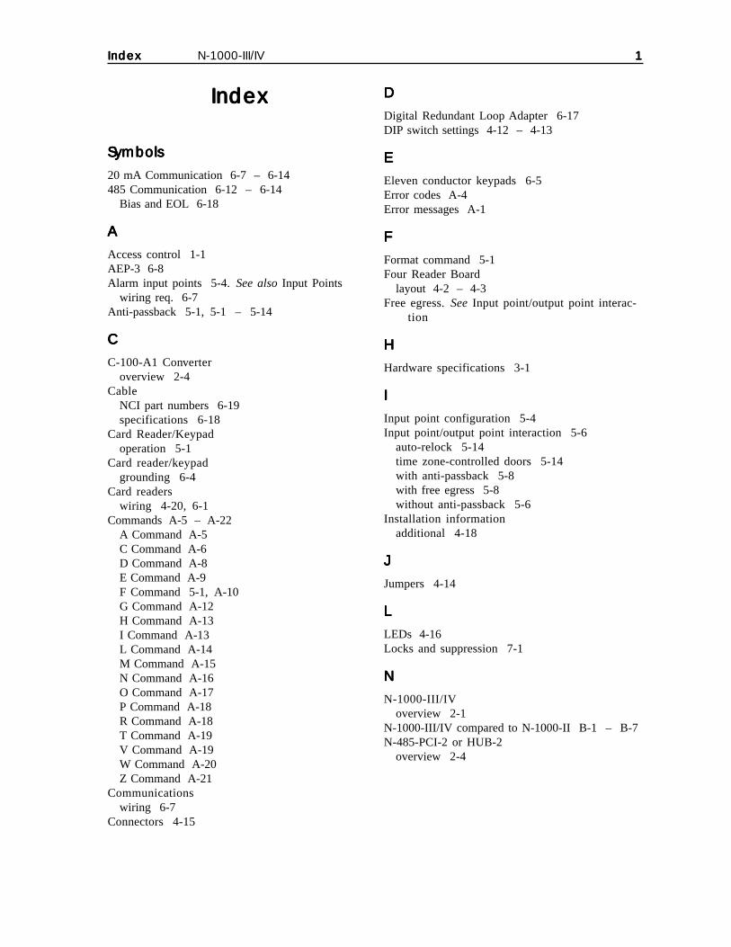
IndexIndexIndexIndexIndex N-1000-III/IV 11111
IndexIndexIndexIndexIndex
SymbolsSymbolsSymbolsSymbolsSymbols
20 mA Communication 6-7 – 6-14485 Communication 6-12 – 6-14
Bias and EOL 6-18
AAAAA
Access control 1-1AEP-3 6-8Alarm input points 5-4.See also Input Points
wiring req. 6-7Anti-passback 5-1, 5-1 – 5-14
CCCCC
C-100-A1 Converteroverview 2-4
CableNCI part numbers 6-19specifications 6-18
Card Reader/Keypadoperation 5-1
Card reader/keypadgrounding 6-4
Card readerswiring 4-20, 6-1
Commands A-5 – A-22A Command A-5C Command A-6D Command A-8E Command A-9F Command 5-1, A-10G Command A-12H Command A-13I Command A-13L Command A-14M Command A-15N Command A-16O Command A-17P Command A-18R Command A-18T Command A-19V Command A-19W Command A-20Z Command A-21
Communicationswiring 6-7
Connectors 4-15
DDDDD
Digital Redundant Loop Adapter 6-17DIP switch settings 4-12 – 4-13
EEEEE
Eleven conductor keypads 6-5Error codes A-4Error messages A-1
FFFFF
Format command 5-1Four Reader Board
layout 4-2 – 4-3Free egress.See Input point/output point interac-
tion
HHHHH
Hardware specifications 3-1
IIIII
Input point configuration 5-4Input point/output point interaction 5-6
auto-relock 5-14time zone-controlled doors 5-14with anti-passback 5-8with free egress 5-8without anti-passback 5-6
Installation informationadditional 4-18
JJJJJ
Jumpers 4-14
LLLLL
LEDs 4-16Locks and suppression 7-1
NNNNN
N-1000-III/IVoverview 2-1
N-1000-III/IV compared to N-1000-II B-1 – B-7N-485-PCI-2 or HUB-2
overview 2-4

22222 N-1000-III/IV IndexIndexIndexIndexIndex
OOOOO
Operation 5-1OR’ing of Inputs A-21Output Groups by readers A-22Output points 5-5.See also Relay Output Points
PPPPP
Panel layout 4-1Parameter variables A-2Power 9-1Programming A-1Programming devices 2-2 – 2-4Programming order A-5PROM chip 4-18PROM versions 2-4
RRRRR
RAM chip 4-18Readers
wire terminations 4-6wiring requirements 6-1 – 6-7
Redundant loop adapter 6-17 see digital redundant loop adapterRelay output points 5-5
wiring requirements 6-7Restart button 4-18RS-232 serial communication ports
configurations 6-20
SSSSS
Self-test C-3System overview 2-1
TTTTT
Terminal blocksTB1, 2, 3, 4 4-4TB5 4-6TB6 4-6TB7 4-8TB8 4-10
TB9 4-10Troubleshooting C-1
circular time zone C-1panel lock-up C-1
WWWWW
Wiring 6-1 – 6-14AEP-3 6-8alarm input points 6-7C-100-A1 6-7card readers 4-6, 4-20, 6-1communication 6-7eleven conductor keypads 6-5example diagram 4-20four reader board 6-3N-485-HUB-2 6-13N-485-PCI-2 6-12relay output points 6-7


K4788
5007 S. Howell Avenue Phone: (414) 769-5980Milwaukee, WI 53207 (800) 323-4576www.nciaccess.com Fax: (414) 769-5989
Leaders in Access Control Technology