Mysteries of the Smith Chart - FARS · Mysteries of the Smith Chart Transmission Lines, Impedance...
81
VG – 1 PSA-00527 — 10/21/2001 Pacificon 2001 Mysteries of the Smith Chart Transmission Lines, Impedance Matching, and Little Known Facts Stephen D. Stearns, K6OIK Chief Technologist TRW Firestorm Wireless Communication Products [email protected]
Transcript of Mysteries of the Smith Chart - FARS · Mysteries of the Smith Chart Transmission Lines, Impedance...

VG – 1PSA-00527 — 10/21/2001
Pacificon 2001
Mysteries of the Smith Chart
Transmission Lines, Impedance Matching,and Little Known Facts
Stephen D. Stearns, K6OIK
Chief Technologist
TRW Firestorm Wireless Communication Products

VG – 2PSA-00527—10/21/2001
Pacificon 2001
Outline
Transmission Line Theory Historical development Heaviside’s rewrite of Maxwell’s theory, Telegrapher’s equations,
Impedance, reflection coefficient, SWR, phase constant, and velocityfactor
Special facts for λ/2, λ/4, and λ/8 lossless lines
The Smith Chart Bilinear complex functions
Impedance and admittance coordinates (circles, circles, and morecircles)
Impedance Matching Why match? Impedance matching vs. conjugate impedance
matching Single frequency matching Multiple-frequency and broadband matching

VG – 3PSA-00527 — 10/21/2001
Pacificon 2001
Part 1: Transmission Line Theory

VG – 4PSA-00527—10/21/2001
Pacificon 2001
Key Dates in Electrical Transmission
1830s Magnetic telegraphs - Gauss, Henry
1839 Electromagnetic telegraph - Wheatstone & Cook
1844 Telegraph in America - Morse
1850s Thousands of miles of telegraph line U.S. and Europe
1851 40-mile cable under English Channel
1855 Distributed analysis of transmission line - Lord Kelvin
1858 Transatlantic cable, project delayed by civil war
1873 Theory of electrodynamics - Maxwell
1876 Invention of telephone - Bell
1880s Vectors, vector calculus, reformulation of Maxwell’stheory, transmission line theory - Heaviside
1886 Experimental confirmation of Maxwell’s Theory - Hertz
1937 Early Smith Chart, published 1939 and 1944 - Smith

VG – 5PSA-00527—10/21/2001
Pacificon 2001
Numbers to Remember!
1.4142135623...
1.7320508075…
1.6180339887...
3.1415926535...
2.718281828459045…
2.54
299,792,458
376.7303134...

VG – 6PSA-00527—10/21/2001
Pacificon 2001
Heaviside’s Vector Formulation of Maxwell’s Theory
∇ × = −
∇ × = +
∇ ⋅ =∇ ⋅ =
==
EBt
H JDt
D
B 0
D E
B H
∂∂
∂∂
ρ
εµ
“And God said, Let there be light; and there was light.” Genesis 1:3

VG – 7PSA-00527—10/21/2001
Pacificon 2001
Frequency Domain or Phasor Form
∇ × = −∇ × = +
∇ ⋅ =∇ ⋅ =
E H
H E
E 0
H 0
j
j
ωµσ ωε( )

VG – 8PSA-00527—10/21/2001
Pacificon 2001
Heaviside’s Telegrapher’s Equations
I(x)
V(x)
dV
dxR j L I x
dI
dxG j C V x
= − +
= − +
( ) ( )
( ) ( )
ω
ω
Uniform transmission line Equivalent circuit of infinitesimal segment
R∆x L∆x
G∆x C∆x
VG – 9PSA-00527—10/21/2001
Pacificon 2001
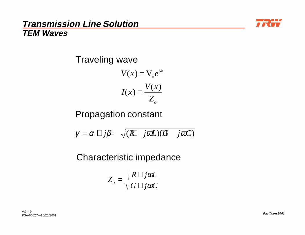
Transmission Line SolutionTEM Waves
V x e
I xV x
Z
x
o
( ) = Voγ
( )( )=
γ α β ω ω= + = + +j R j L G j C( )( )
ZR j L
G j Co = ++
ωω
Traveling wave
Propagation constant
Characteristic impedance
VG – 10PSA-00527—10/21/2001
Pacificon 2001
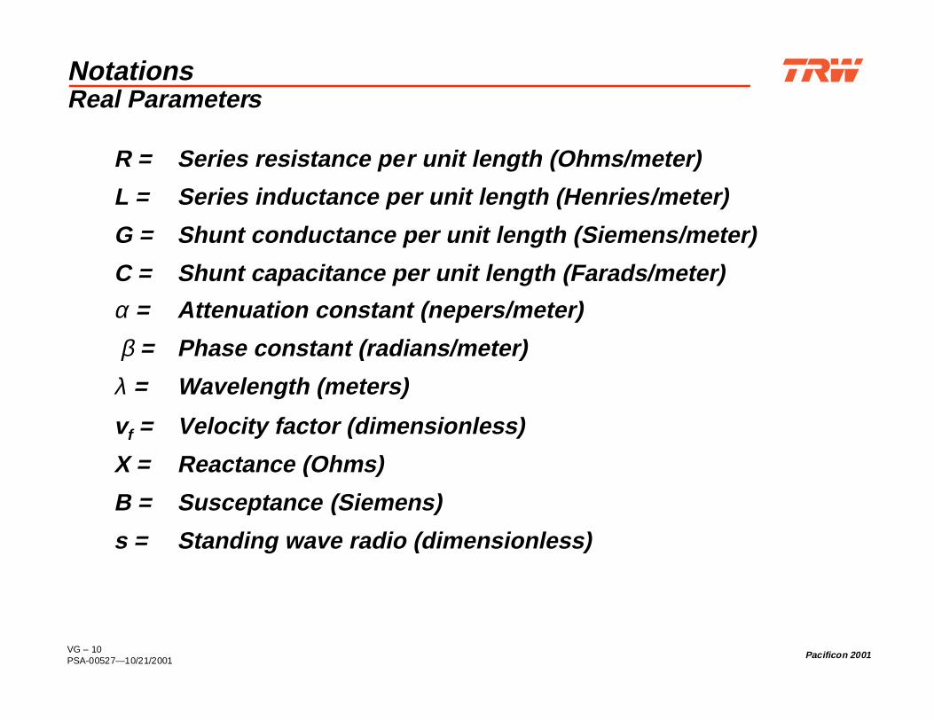
NotationsReal Parameters
R = Series resistance per unit length (Ohms/meter)
L = Series inductance per unit length (Henries/meter)
G = Shunt conductance per unit length (Siemens/meter)
C = Shunt capacitance per unit length (Farads/meter)
α = Attenuation constant (nepers/meter)
β = Phase constant (radians/meter)
λ = Wavelength (meters)
vf = Velocity factor (dimensionless)
X = Reactance (Ohms)
B = Susceptance (Siemens)
s = Standing wave radio (dimensionless)

VG – 11PSA-00527—10/21/2001
Pacificon 2001
Notations (Cont’d)Complex Parameters
Z = R + jX = impedance (Ohms)
ZL = Load impedance (Ohms)
Zi = Input impedance (Ohms)
Z0 = Characteristic impedance (Ohms)
z = Z/Z0 = r + jx = normalized impedance (dimensionless)
Y = G + jB = admittance (Siemens)
y = Y/Y0 = g + jb = normalized admittance (dimensionless)
Γ = Γr + j Γi = complex reflection coefficient (dimensionless)
γ = α + jβ = propagation constant (inverse meters)

VG – 12PSA-00527—10/21/2001
Pacificon 2001
Transmission Line ParametersPhysical Dimensions and Material Properties
a a
d
dielectric(µ, ε, σ)
Parameter Coax Twinlead
R Ω/m
L H/m
G S/m
C F/m
Where skin depth is For copper
1
2
1 1
πδσ c a b+
1
π δσa c
µπ
δ2 2
1 1ln
b
a a b+ +
µπ
δ2 2
1
a
d
a+
−cosh
2πσ
lnb
a
πσ
cosh −1
2
d
a
πε
cosh−1
2
d
a
2πε
lnb
a
δπ µσ
= 1
f c
σ
δµ
c = ×
=
5 8 10
8 5
7.
.
S/m
mm at 60 Hz
6.6 m at 100 MHz
a
b
c
dielectric(µ, ε, σ)

VG – 13PSA-00527—10/21/2001
Pacificon 2001
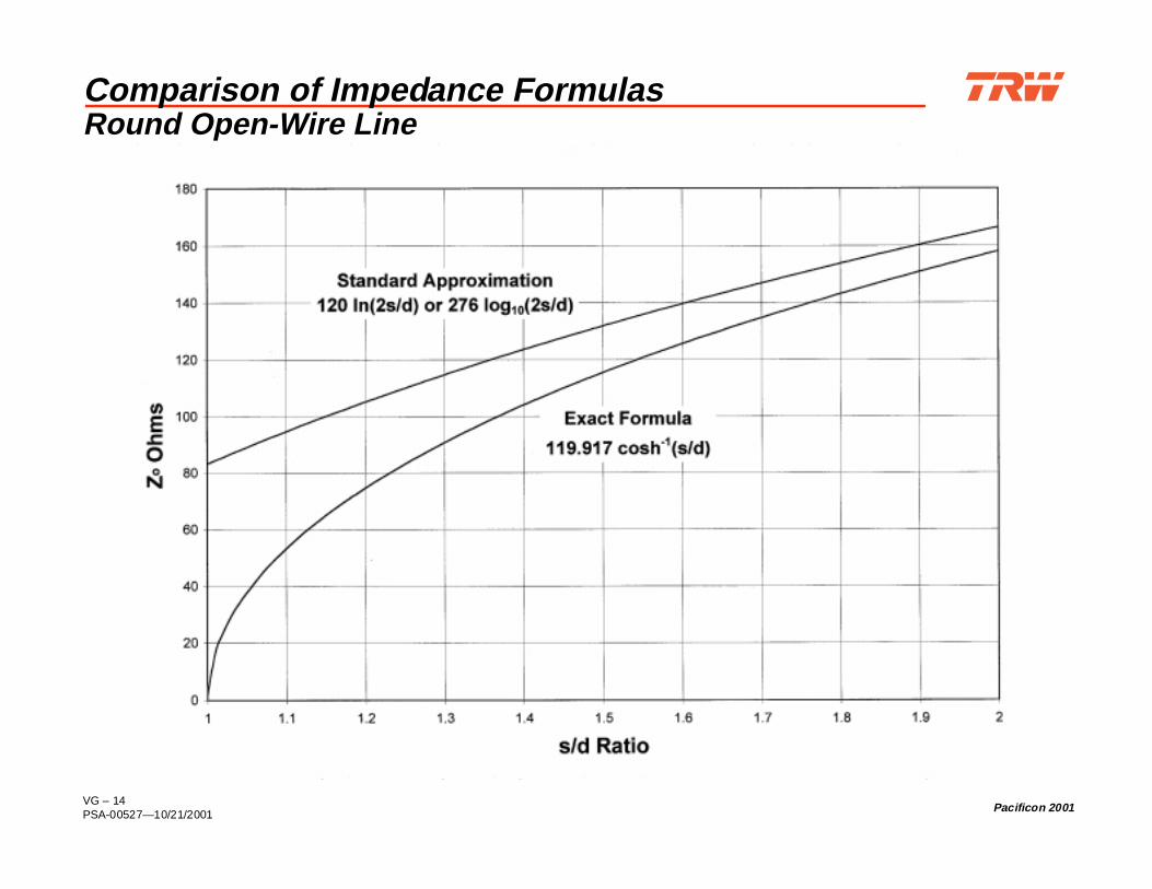
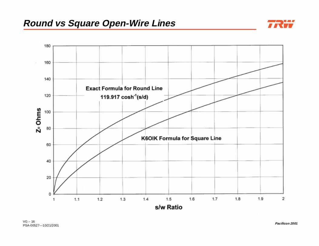
Round Open-Wire Transmission Line Formulas
Approximate formula Widely published by ARRL and others Accurate only for large spacings: s/d > 3
or large impedances: Z0 > several hundred
Exact formula Accurate for all spacings and impedances
s
d
VG – 14PSA-00527—10/21/2001
Pacificon 2001
Comparison of Impedance FormulasRound Open-Wire Line

VG – 15PSA-00527—10/21/2001
Pacificon 2001
K6OIK Square Open-Wire Transmission Line Formula
Excellent approximation in the range of practical interest Accurate for small spacings: 1 < s/w < 3
or small impedances: 0 < Z0 < several hundred
s
w
VG – 16PSA-00527—10/21/2001
Pacificon 2001
Round vs Square Open-Wire Lines
VG – 17PSA-00527—10/21/2001
Pacificon 2001
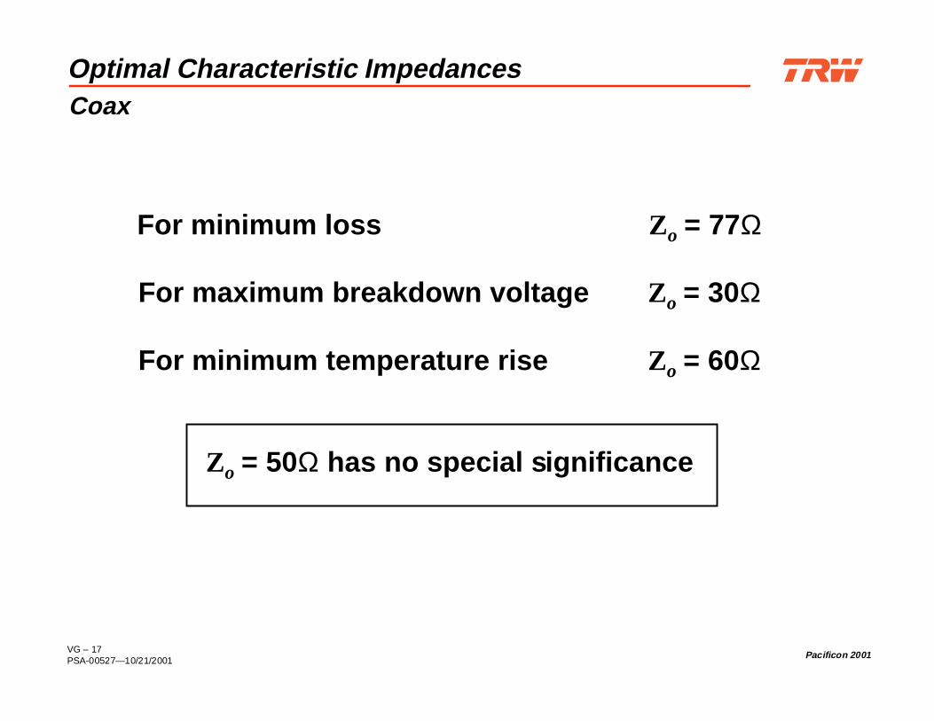
Optimal Characteristic ImpedancesCoax
For minimum loss Zo = 77Ω
For maximum breakdown voltage Zo = 30Ω
For minimum temperature rise Zo = 60Ω
Zo = 50Ω has no special significance

VG – 18PSA-00527—10/21/2001
Pacificon 2001
ΖOΖLΓL
TerminalPlane
Reflection Coefficient and Impedance Relationat a Terminal Plane
For every terminal plane, the complex load impedance andcomplex reflection coefficient seen to the right give the sameinformation for that terminal plane
Question: How do Γ and z change as the terminal planemoves?
Definition
Inverse
Γ =−+
= −+
Z Z
Z Z
z
zL o
L o
1
1
z = +−
1
1
ΓΓ

VG – 19PSA-00527—10/21/2001
Pacificon 2001
Relations Between Two Terminal Planes
ΖOΖLΓL
OutputTerminal
Plane
InputTerminal
Plane
ΖiΓ i
Impedance relation
zz j l
jz liL
L
=+
+tan
tan
ββ1
Reflection coefficient relation
Γ Γi Lj le= − 2β
Cross relations
ze
e
ze
e
iL
j l
Lj l
Li
j l
ij l
=+−
=+−
−
−
1
1
1
1
2
2
2
2
ΓΓ
ΓΓ
β
β
β
β

VG – 20PSA-00527—10/21/2001
Pacificon 2001
Velocity Factor
λ
λ
free space
actual
c
f
v
f
=
=
Velocity factor
vv
cfactual
free space
= =λ
λ
Wavelength

VG – 21PSA-00527—10/21/2001
Pacificon 2001
How To Measure Velocity Factor of a Line(One Way To Do It)
vfl
c Z
Z
fopen
short
=−−
2 1
1
π
cot
AntennaAnalyzer
AntennaAnalyzer
Known length
Same length
opencircuit
shortcircuit

VG – 22PSA-00527—10/21/2001
Pacificon 2001
Phase Constant
Phase constant β and velocity factor vf give equivalentinformation
Both can be calculated from line dimensions and materialproperties
Best to measure!
β πλ
π= =2 2
actual f
f
v c radians/meter
β ω ω= + +Im ( )( )R j L G j C

VG – 23PSA-00527—10/21/2001
Pacificon 2001
Geometric mean of two complex numbers
Calculation is trivial in polar form on Smith Chart
How to Measure Complex Zo of A Line(One Way to Do It)
AntennaAnalyzer
AntennaAnalyzer
Unknown orarbitrary length
Same length
opencircuit
shortcircuit
Z Z Zo open short= ×

VG – 24PSA-00527—10/21/2001
Pacificon 2001
What Special Lengths of Lossless Line Do
Z Zi L=
ZZ
Zio
L
=2
Z Z Z Zi o L o= if and are real (resistive)
Half wavelength, l = _/2
Quarter wavelength, l = _/4
Eighth wavelength, l = _/8

VG – 25PSA-00527—10/21/2001
Pacificon 2001
Standing Wave Ratio
s
s
s
=+−
= −+
1
1
1
1
ΓΓ
Γ
z
z
z
= +−
= −+
1
1
1
1
ΓΓ
Γ
Easy to remember from
VG – 26PSA-00527 — 10/21/2001
Pacificon 2001
Part 2: The Smith Chart

VG – 27PSA-00527 — 10/21/2001
Pacificon 2001
0.10.1
0.1
0.20.2
0.2
0.30.3
0.3
0.40.4
0.4
0.50.5
0.5
0.6
0.6
0.6
0.7
0.7
0.7
0.8
0.8
0.8
0.9
0.9
0.9
1.0
1.0
1.0
1.2
1.2
1.2
1.4
1.4
1.4
1.6
1.6
1.6
1.8
1.8
1.8
2.02.0
2.0
3.03.0
3.0
4.04.0
4.0
5.05.0
5.0
1010
10
2020
20
5050
50
0.20.2
0.20.2
0.40.4
0.40.4
0.60.6
0.60.6
0.80.8
0.80.8
1.01.0
1.01.0
20-20
30-30
40-40
50-50
60-60
70-70
80-80
90-90
100-100
110-110
120-120
130-130
140
-140
150
-150
160
-160
170
-170
180
±
90-9
085
-85
80-8
0
75-7
5
70-7
0
65-6
5
60-6
0
55-5
5
50-5
0
45-45
40-40
35-35
30-30
25-25
20-20
15-15
10-10
0.04
0.04
0.05
0.05
0.06
0.06
0.07
0.07
0.08
0.080.09
0.090.1
0.10.11
0.11
0.12
0.12
0.13
0.13
0.14
0.14
0.15
0.15
0.16
0.16
0.17
0.17
0.18
0.18
0.190.19
0.20.2
0.210.21
0.22
0.220.23
0.230.24
0.24
0.25
0.25
0.26
0.26
0.27
0.27
0.28
0.28
0.29
0.29
0.3
0.3
0.31
0.31
0.320.32
0.330.33
0.340.34
0.350.35
0.360.36
0.37
0.37
0.38
0.38
0.39
0.39
0.4
0.4
0.41
0.41
0.42
0.42
0.430.43
0.44
0.44
0.45
0.45
0.46
0.46
0.47
0.47
0.48
0.48
0.49
0.49
0.0
0.0
AN
GLE O
F TRA
NSM
ISSION
CO
EFFIC
IENT IN
DEG
REES
AN
GLE O
F REFL
EC
TIO
N C
OE
FFICIEN
T IN
DEG
REES
—>
WA
VEL
ENG
THS
TOW
AR
D G
ENER
ATO
R —
><—
WA
VEL
ENG
THS
TOW
AR
D L
OA
D <
—
IND
UC
TIV
E R
EAC
TAN
CE
COM
PON
ENT (+
jX/Zo), O
R CAPACITIVE SUSCEPTANCE (+jB/Yo)
CAPACITIVE REACTANCE COMPONENT (-jX
/Zo), O
R IND
UCTI
VE
SUSC
EPTA
NC
E (-
jB/Y
o)
RESISTANCE COMPONENT (R/Zo), OR CONDUCTANCE COMPONENT (G/Yo)
VG – 28PSA-00527—10/21/2001
Pacificon 2001
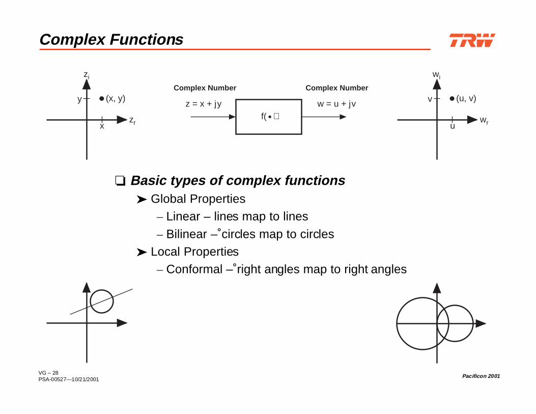
Complex Functions
Basic types of complex functions Global Properties
– Linear – lines map to lines
– Bilinear – circles map to circles Local Properties
– Conformal – right angles map to right angles
z = x + jy
Complex Number
zi
(x, y)
x
y
wi
(u, v)
u
v
wr
w = u + jv
Complex Number
f( )zr

VG – 29PSA-00527—10/21/2001
Pacificon 2001
Mathematical Basis of the Smith Chart
Γ = −+
z
z
u jvr jx
r jx
1
1
1
1+ =
( - ) +
( + ) +
A bilinear conformal complex function
Right HalfZ Plane
r
x
Interior Unit CircleΓ Plane
v
u

VG – 30PSA-00527—10/21/2001
Pacificon 2001
Smith Chart: Impedance Coordinates
r S
erie
s R
esis
tanc
e
Γr
Γi
∞0
x=1
r=0
x=-1
x=0r=1
r=2
x Series Reactance
0.1
0.1
0.1
0.2
0.2
0.2
0.3
0.3
0.3
0.4
0.4
0.4
0.50.5
0.5
0.6
0.6
0.6
0.7
0.7
0.7
0.8
0.8
0.8
0.9
0.9
0.9
1.0
1.0
1.0
1.2
1.2
1.2
1.4
1.4
1.4
1.6
1.6
1.6
1.8
1.8
1.8
2.02.0
2.0
3.0
3.0
3.0
4.0
4.0
4.0
5.0
5.0
5.0
10
10
10
20
20
20
50
50
50
0.2
0.2
0.2
0.2
0.4
0.4
0.4
0.4
0.6
0.6
0.6
0.6
0.8
0.8
0.8
0.8
1.0
1.0
1.01.0
20-20
30-30
40-40
50
-50
60
-60
70
-70
80
-80
90
-90
100
-100
110
-110
120
-120
130
-130
140
-140
150
-150
160
-160
170
-170
180
±
90-9
085
-85
80-8
0
75-7
5
70-7
0
65-6
5
60-6
0
55-5
5
50-5
0
45-45
40
-40
35
-35
30
-30
25
-25
20
-20
15
-15
10
-10
0.04
0.04
0.05
0.05
0.06
0.06
0.07
0.07
0.08
0.08
0.09
0.09
0.1
0.1
0.11
0.11
0.12
0.12
0.13
0.13
0.14
0.14
0.15
0.15
0.16
0.160.17
0.170.18
0.18
0.190.19
0.20.2
0.210.21
0.22
0.220.23
0.230.24
0.24
0.25
0.25
0.26
0.26
0.27
0.27
0.28
0.28
0.29
0.29
0.3
0.3
0.31
0.31
0.32
0.32
0.33
0.33
0.34
0.34
0.35
0.35
0.36
0.36
0.37
0.37
0.38
0.38
0.39
0.39
0.4
0.4
0.41
0.41
0.42
0.42
0.43
0.43
0.44
0.44
0.45
0.45
0.46
0.46
0.47
0.47
0.48
0.48
0.49
0.49
0.0
0.0
AN
GLE
OF
TRA
NSM
ISSION
CO
EFFIC
IENT
IND
EGR
EES
AN
GLE
OF
REFLE
CT
ION
CO
EFFIC
IENT
IND
EGR
EES
—>
WA
VEL
ENG
THS
TOW
AR
DG
ENER
ATO
R—
><—
WA
VEL
ENG
THS
TOW
AR
DLO
AD
<—
IND
UC
TIV
ER
EAC
TAN
CE
COM
PON
ENT
(+jX
/Zo), OR
CAPACITIVE SUSCEPTANCE (+jB/Yo)
CAPACITIVEREACTANCECOMPONENT(-jX/Zo)
,OR
IND
UCTI
VE
SUSC
EPTA
NC
E(-
jB/Y
o)
RESISTANCE COMPONENT (R/Zo), OR CONDUCTANCE COMPONENT (G/Yo)
InductiveReactance(Positive)
CapacitiveReactance(Negative)
x=0
x=1r=1
r=2
x=-1
r=0

VG – 31PSA-00527—10/21/2001
Pacificon 2001
Smith Chart: Admittance Coordinates
Shu
nt C
ondu
ctan
ce
Γr
Γi
∞ 0
b=1
g=0
b=-1
b=0g=1
g=2
Shunt Susceptance
0.1
0.1
0.1
0.2
0.2
0.2
0.3
0.3
0.3
0.4
0.4
0.4
0.50.5
0.5
0.60.6
0.6
0.70.7
0.7
0.80.8
0.80.9
0.9
0.9
1.01.0
1.0
1.21.2
1.2
1.41.4
1.4
1.61.6
1.6
1.81.8
1.8
2.02.0
2.0
3.0
3.0
3.0
4.0
4.0
4.0
5.0
5.0
5.0
10
10
10
20
20
20
50
50
50
0.2
0.2
0.2
0.2
0.4
0.4
0.4
0.4
0.6
0.6
0.6
0.6
0.8
0.8
0.8
0.8
1.0
1.0
1.01.0
20-2
0
30-3
0
40-4
0
50
-50
60
-60
70
-70
80
-80
90
-90
100
-100
110
-110
120
-120130
-130
140-140
150-150
160-160
170-170
180±
90-90
85-85
80-80
75-75
70-70
65-65
60-60
55-55
50-50
45-45
40
-40
35
-35
30
-3025
-2520
-2015
-1510
-10
0.04
0.04
0.05
0.05
0.06
0.06
0.07
0.07
0.08
0.08
0.09
0.09
0.1
0.1
0.11
0.11
0.12
0.12
0.13
0.13
0.14
0.14
0.15
0.15
0.16
0.16
0.17
0.17
0.18
0.18
0.19
0.19
0.2
0.2
0.21
0.21
0.22
0.22
0.23
0.23
0.24
0.24
0.25
0.25
0.26
0.26
0.27
0.27
0.28
0.28
0.29
0.29
0.3
0.3
0.31
0.31
0.32
0.32
0.33
0.33
0.34
0.34
0.35
0.35
0.36
0.36
0.37
0.37
0.38
0.38
0.39
0.39
0.4
0.4
0.41
0.410.42
0.420.43
0.43
0.440.44
0.450.45
0.460.46
0.47
0.470.48
0.480.49
0.49
0.0
0.0
AN
GLE
OF
TRA
NSM
ISSI
ON
CO
EFF
ICIE
NT
IND
EGR
EES
AN
GLE
OF
REF
LEC
TIO
NC
OE
FFIC
IEN
TIN
DEG
REE
S
—>
WA
VELEN
GTH
STO
WA
RD
GEN
ERA
TOR
—>
<—W
AV
ELENG
THS
TOW
AR
DLO
AD
<—
IND
UC
TIVE
REA
CTA
NC
ECO
MPO
NEN
T(+jX/Zo),OR
CAPACITIVESUSCEPTANCE(+jB/Yo)
CAPACITIVE REACTANCE COMPONENT (-jX/Zo), ORIN
DU
CTIVE
SUSC
EPTAN
CE
(-jB/Yo)
RESISTANCE COMPONENT (R/Zo), OR CONDUCTANCE COMPONENT (G/Yo)
b
gb=0
b=1
g=1
g=2
b=-1
g=0
InductiveSusceptance
(Negative)
CapacitiveSusceptance
(Positive)

VG – 32PSA-00527—10/21/2001
Pacificon 2001
Smith Chart: Constant SWR Circles
0.1
0.1
0.1
0.2
0.2
0.2
0.3
0.3
0.3
0.4
0.4
0.4
0.50.5
0.5
0.6
0.6
0.6
0.7
0.7
0.7
0.8
0.8
0.8
0.9
0.9
0.9
1.0
1.0
1.0
1.2
1.2
1.2
1.4
1.4
1.4
1.6
1.6
1.6
1.8
1.8
1.8
2.02.0
2.0
3.0
3.0
3.0
4.0
4.0
4.0
5.0
5.0
5.0
10
10
10
20
20
20
50
50
50
0.2
0.2
0.2
0.2
0.4
0.4
0.4
0.4
0.6
0.6
0.6
0.6
0.8
0.8
0.8
0.8
1.0
1.0
1.01.0
20-20
30-30
40-40
50
-50
60
-60
70
-70
80
-80
90
-90
100
-100
110
-110
120
-120
130
-130
140
-140
150
-150
160
-160
170
-170
180
±
90-9
085
-85
80-8
0
75-7
5
70-7
0
65-6
5
60-6
0
55-5
5
50-5
0
45-45
40
-40
35
-35
30
-30
25
-25
20
-20
15
-15
10
-100.
04
0.04
0.05
0.05
0.06
0.06
0.07
0.07
0.08
0.08
0.09
0.09
0.1
0.1
0.11
0.11
0.12
0.12
0.13
0.13
0.14
0.14
0.15
0.15
0.16
0.16
0.17
0.17
0.18
0.18
0.190.19
0.20.2
0.210.21
0.22
0.220.23
0.230.24
0.24
0.25
0.25
0.26
0.26
0.27
0.27
0.28
0.28
0.29
0.29
0.3
0.3
0.31
0.31
0.32
0.32
0.33
0.33
0.34
0.34
0.35
0.35
0.36
0.36
0.37
0.37
0.38
0.38
0.39
0.39
0.4
0.4
0.41
0.41
0.42
0.42
0.43
0.43
0.44
0.44
0.45
0.45
0.46
0.46
0.47
0.47
0.48
0.48
0.49
0.49
0.0
0.0
AN
GLE
OF
TRA
NSM
ISSION
CO
EFFIC
IENT
IND
EGR
EES
AN
GLE
OF
REFLE
CT
ION
CO
EFFIC
IENT
IND
EGR
EES
—>
WA
VEL
ENG
THS
TOW
AR
DG
ENER
ATO
R—
><—
WA
VEL
ENG
THS
TOW
AR
DLO
AD
<—
IND
UC
TIV
ER
EAC
TAN
CE
COM
PON
ENT
(+jX
/Zo), OR
CAPACITIVE SUSCEPTANCE (+jB/Yo)
CAPACITIVEREACTANCECOMPONENT(-jX/Zo)
,OR
IND
UCTI
VE
SUSC
EPTA
NC
E(-
jB/Y
o)
RESISTANCE COMPONENT (R/Zo), OR CONDUCTANCE COMPONENT (G/Yo) 2 3 41.5Γr
Γ i
VG – 33PSA-00527—10/21/2001
Pacificon 2001
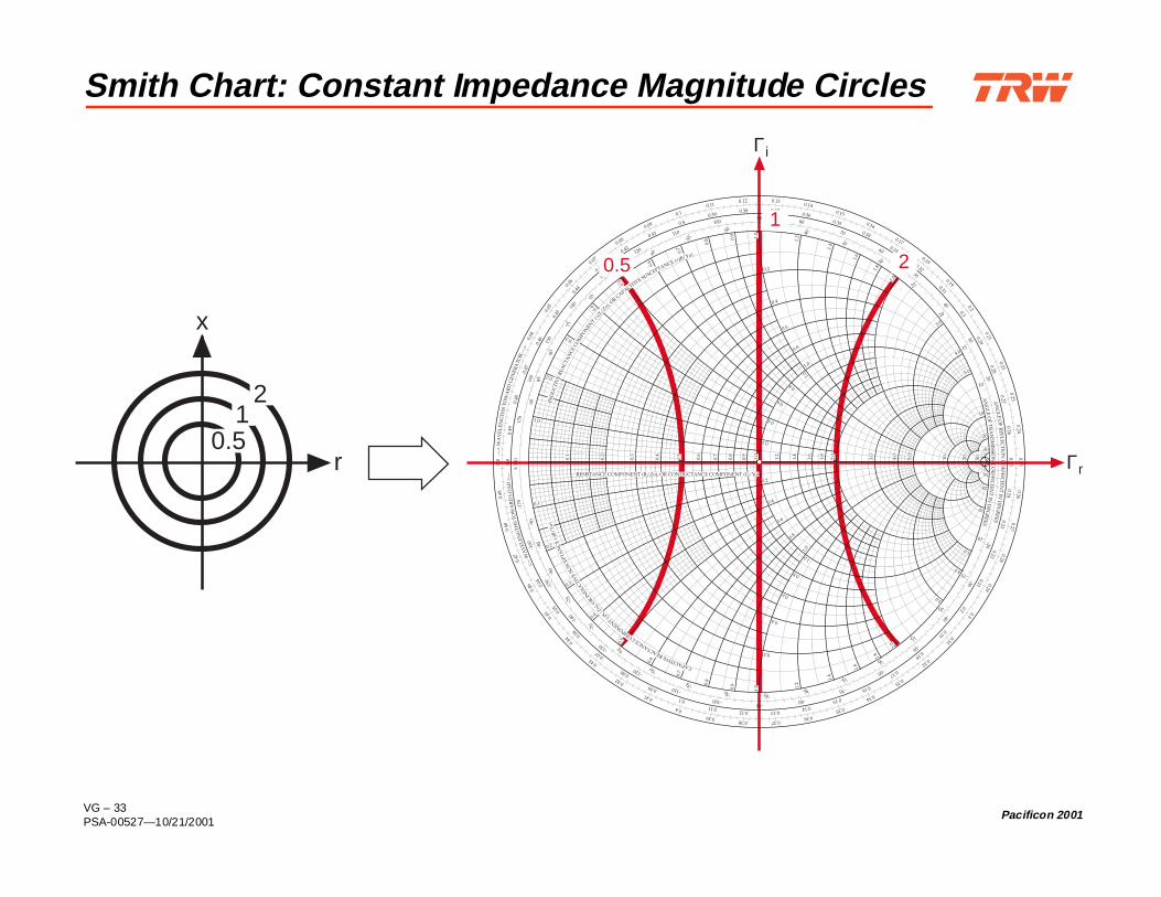
Smith Chart: Constant Impedance Magnitude Circles
Γr
Γ i
x
r0.5
12
0.1
0.1
0.1
0.2
0.2
0.2
0.3
0.3
0.3
0.4
0.4
0.4
0.50.5
0.5
0.6
0.6
0.6
0.7
0.7
0.7
0.8
0.8
0.8
0.9
0.9
0.9
1.0
1.0
1.0
1.2
1.2
1.2
1.4
1.4
1.4
1.6
1.6
1.6
1.8
1.8
1.8
2.02.0
2.0
3.0
3.0
3.0
4.0
4.0
4.0
5.0
5.0
5.0
10
10
10
20
20
20
50
50
50
0.2
0.2
0.2
0.2
0.4
0.4
0.4
0.4
0.6
0.6
0.6
0.6
0.8
0.8
0.8
0.8
1.0
1.0
1.01.0
20-20
30-30
40-40
50
-50
60
-60
70
-70
80
-80
90
-90
100
-100
110
-110
120
-120
130
-130
140
-140
150
-150
160
-160
170
-170
180
±
90-9
085
-85
80-8
0
75-7
5
70-7
0
65-6
5
60-6
0
55-5
5
50-5
0
45-45
40
-40
35
-35
30
-30
25
-25
20
-20
15
-15
10
-10
0.04
0.04
0.05
0.05
0.06
0.06
0.07
0.07
0.08
0.08
0.09
0.09
0.1
0.1
0.11
0.11
0.12
0.12
0.13
0.13
0.14
0.14
0.15
0.15
0.16
0.160.17
0.170.18
0.18
0.190.19
0.20.2
0.210.21
0.22
0.220.23
0.230.24
0.24
0.25
0.25
0.26
0.26
0.27
0.27
0.28
0.28
0.29
0.29
0.3
0.3
0.31
0.31
0.32
0.32
0.33
0.33
0.34
0.34
0.35
0.35
0.36
0.36
0.37
0.37
0.38
0.38
0.39
0.39
0.4
0.4
0.41
0.41
0.42
0.42
0.43
0.43
0.44
0.44
0.45
0.45
0.46
0.46
0.47
0.47
0.48
0.48
0.49
0.49
0.0
0.0
AN
GLE
OF
TRA
NSM
ISSION
CO
EFFIC
IENT
IND
EGR
EES
AN
GLE
OF
REFLEC
TIO
NC
OE
FFICIEN
TIN
DEG
REES
—>
WA
VEL
ENG
THS
TOW
AR
DG
ENER
ATO
R—
><—
WA
VEL
ENG
THS
TOW
AR
DLO
AD
<—
IND
UC
TIV
ER
EAC
TAN
CE
COM
PON
ENT
(+jX
/Zo), OR
CAPACITIVE SUSCEPTANCE (+jB/Yo)
CAPACITIVEREACTANCECOMPONENT(-jX/Zo)
,OR
IND
UCTI
VE
SUSC
EPTA
NC
E(-
jB/Y
o)
RESISTANCE COMPONENT (R/Zo), OR CONDUCTANCE COMPONENT (G/Yo)
0.5 2
1

VG – 34PSA-00527—10/21/2001
Pacificon 2001
Smith Chart: Constant Impedance Phase Angle Circles
Γr
Γ i
x
90°
45°
0°
315°
270°22
5°
180°
135° 0.1
0.1
0.1
0.2
0.2
0.2
0.3
0.3
0.3
0.4
0.40.
4
0.50.5
0.5
0.6
0.6
0.6
0.7
0.7
0.7
0.8
0.8
0.8
0.9
0.9
0.9
1.0
1.0
1.0
1.2
1.2
1.2
1.4
1.4
1.4
1.6
1.6
1.6
1.8
1.8
1.8
2.02.0
2.0
3.0
3.0
3.0
4.0
4.0
4.0
5.0
5.0
5.0
10
10
10
20
20
20
50
50
50
0.2
0.2
0.2
0.2
0.4
0.4
0.4
0.4
0.6
0.6
0.6
0.6
0.8
0.8
0.8
0.8
1.0
1.0
1.01.0
20-20
30-30
40-40
50
-50
60
-60
70
-70
80
-80
90
-90
100
-100
110
-110
120
-120
130
-130
140
-140
150
-150
160
-160
170
-170
180
±
90-9
085
-85
80-8
0
75-7
5
70-7
0
65-6
5
60-6
0
55-5
5
50-5
0
45-45
40
-40
35
-35
30
-30
25
-25
20
-20
15
-15
10
-10
0.04
0.04
0.05
0.05
0.06
0.06
0.07
0.07
0.08
0.08
0.09
0.09
0.1
0.1
0.11
0.11
0.12
0.12
0.13
0.13
0.14
0.14
0.15
0.15
0.16
0.16
0.17
0.17
0.18
0.18
0.190.19
0.20.2
0.210.21
0.22
0.220.23
0.230.24
0.24
0.25
0.25
0.26
0.26
0.27
0.27
0.28
0.28
0.29
0.29
0.3
0.3
0.31
0.31
0.32
0.32
0.33
0.33
0.34
0.34
0.35
0.35
0.36
0.36
0.37
0.37
0.38
0.38
0.39
0.39
0.4
0.4
0.41
0.41
0.42
0.42
0.43
0.43
0.44
0.44
0.45
0.45
0.46
0.46
0.47
0.47
0.48
0.48
0.49
0.49
0.0
0.0
AN
GLE
OF
TRA
NSM
ISSION
CO
EFFIC
IENT
IND
EGR
EES
AN
GLE
OF
REFLEC
TIO
NC
OE
FFICIEN
TIN
DEG
REES
—>
WA
VEL
ENG
THS
TOW
AR
DG
ENER
ATO
R—
><—
WA
VEL
ENG
THS
TOW
AR
DLO
AD
<—
IND
UC
TIV
ER
EAC
TAN
CE
COM
PON
ENT
(+jX
/Zo), OR
CAPACITIVE SUSCEPTANCE (+jB/Yo)
CAPACITIVEREACTANCECOMPONENT(-jX/Zo)
,OR
IND
UCTI
VE
SUSC
EPTA
NC
E(-
jB/Y
o)
RESISTANCE COMPONENT (R/Zo), OR CONDUCTANCE COMPONENT (G/Yo)
0°
45°
315°

VG – 35PSA-00527—10/21/2001
Pacificon 2001
Smith Chart: Multiplication, Division, Squares, andSquare Roots
Unary Operatorssquares a2
square rootstangents tan θcotangents cot θinverse tangents tan-1 aInverse cotangents cot-1 a
Binary Operatorsmultiplication X a • bdivision ÷ c/a
geometric mean
a
ab

VG – 36PSA-00527—10/21/2001
Pacificon 2001
Smith Chart: A Nomogram for Math Calculations
Γr
Γi
0.1
0.1
0.1
0.2
0.2
0.2
0.3
0.3
0.3
0.4
0.4
0.4
0.50.5
0.5
0.6
0.6
0.6
0.7
0.7
0.7
0.8
0.8
0.8
0.9
0.9
0.9
1.0
1.0
1.0
1.2
1.2
1.2
1.4
1.4
1.4
1.6
1.6
1.6
1.8
1.8
1.8
2.02.0
2.0
3.0
3.0
3.0
4.0
4.0
4.0
5.0
5.0
5.0
10
10
10
20
20
20
50
50
50
0.2
0.2
0.2
0.2
0.4
0.4
0.4
0.4
0.6
0.6
0.6
0.6
0.8
0.8
0.8
0.8
1.0
1.0
1.01.0
20-20
30-30
40-40
50
-50
60
-60
70
-70
80
-80
90
-90
100
-100
110
-110
120
-120
130
-130
140
-140
150
-150
160
-160
170
-170
180
±
90-9
085
-85
80-8
0
75-7
5
70-7
0
65-6
5
60-6
0
55-5
5
50-5
0
45-45
40
-40
35
-35
30
-30
25
-25
20
-20
15
-15
10
-100.
04
0.04
0.05
0.05
0.06
0.06
0.07
0.07
0.08
0.08
0.09
0.09
0.1
0.1
0.11
0.11
0.12
0.12
0.13
0.13
0.14
0.14
0.15
0.15
0.16
0.16
0.17
0.17
0.18
0.18
0.190.19
0.20.2
0.210.21
0.22
0.220.23
0.230.24
0.24
0.25
0.25
0.26
0.26
0.27
0.27
0.28
0.28
0.29
0.29
0.3
0.3
0.31
0.31
0.32
0.32
0.33
0.33
0.34
0.34
0.35
0.35
0.36
0.36
0.37
0.37
0.38
0.38
0.39
0.39
0.4
0.4
0.41
0.41
0.42
0.42
0.43
0.43
0.44
0.44
0.45
0.45
0.46
0.46
0.47
0.47
0.48
0.48
0.49
0.49
0.0
0.0
AN
GLE
OF
TRA
NSM
ISSION
CO
EFFIC
IENT
IND
EGR
EES
AN
GLE
OF
REFLEC
TIO
NC
OE
FFICIEN
TIN
DEG
REES
—>
WA
VEL
ENG
THS
TOW
AR
DG
ENER
ATO
R—
><—
WA
VEL
ENG
THS
TOW
AR
DLO
AD
<—
IND
UC
TIV
ER
EAC
TAN
CE
COM
PON
ENT
(+jX
/Zo), OR
CAPACITIVE SUSCEPTANCE (+jB/Yo)
CAPACITIVEREACTANCECOMPONENT(-jX/Zo)
,OR
IND
UCTI
VE
SUSC
EPTA
NC
E(-
jB/Y
o)
RESISTANCE COMPONENT (R/Zo), OR CONDUCTANCE COMPONENT (G/Yo)
√c=1.414
a=4
c=2
b=0.5
-√2

VG – 37PSA-00527 — 10/21/2001
Pacificon 2001
Part 3: Impedance Matching
VG – 38PSA-00527—10/21/2001
Pacificon 2001
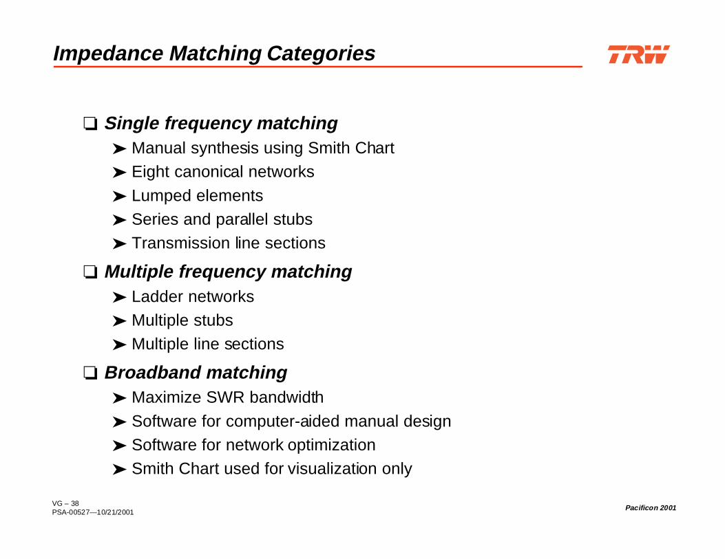
Impedance Matching Categories
Single frequency matching Manual synthesis using Smith Chart Eight canonical networks
Lumped elements Series and parallel stubs Transmission line sections
Multiple frequency matching Ladder networks Multiple stubs Multiple line sections
Broadband matching Maximize SWR bandwidth
Software for computer-aided manual design Software for network optimization Smith Chart used for visualization only

VG – 39PSA-00527—10/21/2001
Pacificon 2001
Bandwidth Classifications
Narrowband < 10%
Moderate band 10% to 50%
Broadband > 50%
Fractional Bandwidth

VG – 40PSA-00527—10/21/2001
Pacificon 2001
Two Kinds of Matching
Conjugate Matching
Best use at source(transmitter)
Maximizes power delivery tothe load
Does not minimize reflectionsunless Zs is real
Normally done by thetransmitter manufacturer at thecircuit design level
Ideally Zs (ext) = 50 Ω
Load Matching
Best used at ends of transmissionlines
Minimizes reflections
Does not maximize deliveredpower unless Z0 is real
ΖS
∼+
-
ΖLΖO ΖL
Zs = ZL* ZL = ZO
VG – 41PSA-00527—10/21/2001
Pacificon 2001
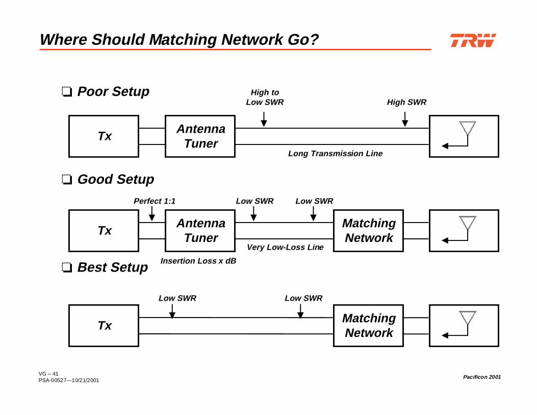
Where Should Matching Network Go?
Poor Setup
Good Setup
Best Setup
Tx
High toLow SWR
AntennaTuner
High SWR
Long Transmission Line
Tx MatchingNetwork
Low SWR Low SWR
Tx AntennaTuner
MatchingNetwork
Perfect 1:1 Low SWR
Very Low-Loss Line
Low SWR
Insertion Loss x dB

VG – 42PSA-00527—10/21/2001
Pacificon 2001
Necessary Test Equipment
Antenna analyzer Autek CIA MFJ
Noise bridge (less accurate)
Network analyzer (more accurate) Hewlett-Packard

VG – 43PSA-00527—10/21/2001
Pacificon 2001
Matching Network Design Recipe
1. Measure transmission line parameters Zo, vf
2. Measure antenna feedpoint impedance across band(s) of interest
3. Measure or calculate impedance across band(s) of interest at networkinsertion point
4. Narrowband match: Select appropriate lossless L network, 2 or 4 choices Select lumped elements vs stubs Calculate component values Calculate SWR and SWR bandwidth Build and test
5. Broadband match: Use design software - winSMITH or equivalent Design n-stage lossless ladder network Select lumped elements vs stubs Calculate component values Calculate SWR and SWR bandwidth

VG – 44PSA-00527—10/21/2001
Pacificon 2001
How to Measure Antenna Feedpoint Impedance
Measure impedance through known line
Divide measure impedance by Zo
Plot impedance point on Smith Chart
Move counter clockwise on chart by electrical length of line
Read coordinate values from chart
Multiply result by Zo

VG – 45PSA-00527—10/21/2001
Pacificon 2001
Smith Chart: Effect of Adding Series Reactances orShunt Susceptances
Γ
Γi
r
0.1
0.1
0.1
0.2
0.2
0.2
0.3
0.3
0.3
0.4
0.4
0.4
0.50.5
0.5
0.6
0.6
0.6
0.7
0.7
0.7
0.8
0.8
0.8
0.9
0.9
0.9
1.0
1.0
1.0
1.2
1.2
1.2
1.4
1.4
1.4
1.6
1.6
1.6
1.8
1.8
1.8
2.02.0
2.0
3.0
3.0
3.0
4.0
4.0
4.0
5.0
5.0
5.0
10
10
10
20
20
20
50
50
50
0.2
0.2
0.2
0.2
0.4
0.4
0.4
0.4
0.6
0.6
0.6
0.6
0.8
0.8
0.8
0.8
1.0
1.0
1.01.0
20-20
30-30
40-40
50
-50
60
-60
70
-70
80
-80
90
-90
100
-100
110
-110
120
-120
130
-130
140
-140
150
-150
160
-160
170
-170
180
±
90-9
085
-85
80-8
0
75-7
5
70-7
0
65-6
5
60-6
0
55-5
5
50-5
0
45-45
40
-40
35
-35
30
-30
25
-25
20
-20
15
-15
10
-10
0.04
0.04
0.05
0.05
0.06
0.06
0.07
0.07
0.08
0.08
0.09
0.09
0.1
0.1
0.11
0.11
0.12
0.12
0.13
0.13
0.14
0.14
0.15
0.15
0.16
0.16
0.17
0.17
0.18
0.18
0.190.19
0.20.2
0.210.21
0.22
0.220.23
0.230.24
0.24
0.25
0.25
0.26
0.26
0.27
0.27
0.28
0.28
0.29
0.29
0.3
0.3
0.31
0.31
0.32
0.32
0.33
0.33
0.34
0.34
0.35
0.35
0.36
0.36
0.37
0.37
0.38
0.38
0.39
0.39
0.4
0.4
0.41
0.41
0.42
0.42
0.43
0.43
0.44
0.44
0.45
0.45
0.46
0.46
0.47
0.47
0.48
0.48
0.49
0.49
0.0
0.0
AN
GLE O
F TRA
NSM
ISSION
CO
EFFIC
IENT IN
DEG
REES
AN
GLE O
F REFLEC
TIO
N C
OE
FFICIEN
T IN
DEG
REES
> W
AV
ELEN
GTH
S TO
WA
RD
GEN
ERA
TOR
>
< W
AV
ELEN
GTH
S TO
WA
RD
LO
AD
<
IND
UC
TIV
E R
EAC
TAN
CE
COM
PON
ENT (+
jX/Zo), O
R CAPACITIVE SUSCEPTANCE (+jB/Yo)
CAPACITIVE REACTANCE COMPONENT (-
jX/Zo)
, OR IN
DU
CTIV
E SU
SCEP
TAN
CE
(-jB
/Yo)
RESISTANCE COMPONENT (R/Zo), OR CONDUCTANCE COMPONENT (G/Yo)
+b
+x
-b
-x

VG – 46PSA-00527 — 10/21/2001
Pacificon 2001
0.1
0.1
0.1
0.2
0.2
0.2
0.3
0.3
0.3
0.4
0.4
0.4
0.50.5
0.5
0.6
0.6
0.6
0.7
0.7
0.7
0.8
0.8
0.8
0.9
0.9
0.9
1.0
1.0
1.0
1.2
1.2
1.2
1.4
1.4
1.4
1.6
1.6
1.6
1.8
1.8
1.8
2.02.0
2.0
3.0
3.0
3.0
4.0
4.0
4.0
5.0
5.0
5.0
10
10
10
20
20
20
50
50
50
0.2
0.2
0.2
0.2
0.4
0.4
0.4
0.4
0.6
0.6
0.6
0.6
0.8
0.8
0.8
0.8
1.0
1.0
1.01.0
20-20
30-30
40-40
50
-50
60
-60
70
-70
80
-80
90
-90
100
-100
110
-110120
-120130
-130
140
-140
150
-150
160
-160
170
-170
180
±
90-9
085
-85
80-8
0
75-7
5
70-7
0
65-6
5
60-6
0
55-5
5
50-5
0
45-45
40
-40
35
-3530
-3025
-25
20
-20
15
-15
10
-10
0.04
0.04
0.05
0.05
0.06
0.06
0.07
0.07
0.08
0.08
0.09
0.09
0.1
0.1
0.11
0.11
0.12
0.12
0.13
0.13
0.14
0.14
0.15
0.15
0.16
0.16
0.17
0.17
0.18
0.18
0.190.19
0.20.2
0.210.21
0.22
0.220.23
0.230.24
0.24
0.25
0.25
0.26
0.26
0.27
0.27
0.28
0.28
0.29
0.29
0.3
0.3
0.31
0.31
0.32
0.32
0.33
0.33
0.34
0.34
0.35
0.35
0.36
0.36
0.37
0.37
0.38
0.380.39
0.390.4
0.40.41
0.410.42
0.42
0.43
0.43
0.44
0.44
0.45
0.45
0.46
0.46
0.47
0.47
0.48
0.48
0.49
0.49
0.0
0.0
AN
GLE O
F TRA
NSM
ISSION
CO
EFFIC
IENT IN
DEG
REES
AN
GLE O
F REFL
EC
TIO
N C
OE
FFICIE
NT
IN D
EGR
EES
—>
WA
VEL
ENG
THS
TOW
AR
D G
ENER
ATO
R —
><—
WA
VEL
ENG
THS
TOW
AR
D L
OA
D <
—
IND
UC
TIV
E R
EAC
TAN
CE
COM
PON
ENT (+
jX/Zo), O
R CAPACITIVE SUSCEPTANCE (+jB/Yo)
CAPACITIVE REACTANCE COMPONENT (-
jX/Zo)
, OR IN
DU
CTIV
E SU
SCEP
TAN
CE
(-jB
/Yo)
RESISTANCE COMPONENT (R/Zo), OR CONDUCTANCE COMPONENT (G/Yo)
Z
(a)
0 Z
Forbidden Area

VG – 47PSA-00527 — 10/21/2001
Pacificon 2001
0.1
0.1
0.1
0.2
0.2
0.2
0.3
0.3
0.3
0.4
0.4
0.4
0.50.5
0.5
0.6
0.6
0.6
0.7
0.7
0.7
0.8
0.8
0.8
0.9
0.9
0.9
1.0
1.0
1.0
1.2
1.2
1.2
1.4
1.4
1.4
1.6
1.6
1.6
1.8
1.8
1.8
2.02.0
2.0
3.0
3.0
3.0
4.0
4.0
4.0
5.0
5.0
5.0
10
10
10
20
20
20
50
50
50
0.2
0.2
0.2
0.2
0.4
0.4
0.4
0.4
0.6
0.6
0.6
0.6
0.8
0.8
0.8
0.8
1.0
1.0
1.01.0
20-20
30-30
40-40
50
-50
60
-60
70
-70
80
-80
90
-90
100
-100
110
-110120
-120130
-130
140
-140
150
-150
160
-160
170
-170
180
±
90-9
085
-85
80-8
0
75-7
5
70-7
0
65-6
5
60-6
0
55-5
5
50-5
0
45-45
40
-40
35
-3530
-3025
-2520
-20
15
-15
10
-10
0.04
0.04
0.05
0.05
0.06
0.06
0.07
0.07
0.08
0.08
0.09
0.09
0.1
0.1
0.11
0.11
0.12
0.12
0.13
0.13
0.14
0.14
0.15
0.15
0.16
0.16
0.17
0.17
0.18
0.18
0.190.19
0.20.2
0.210.21
0.22
0.220.23
0.230.24
0.24
0.25
0.25
0.26
0.26
0.27
0.27
0.28
0.28
0.29
0.29
0.3
0.3
0.31
0.31
0.32
0.32
0.33
0.33
0.34
0.34
0.35
0.35
0.36
0.36
0.37
0.37
0.38
0.38
0.39
0.390.4
0.40.41
0.410.42
0.420.43
0.43
0.44
0.44
0.45
0.45
0.46
0.46
0.47
0.47
0.48
0.48
0.49
0.49
0.0
0.0
AN
GLE O
F TRA
NSM
ISSION
CO
EFFIC
IENT IN
DEG
REES
AN
GLE O
F REFL
EC
TIO
N C
OE
FFICIE
NT
IN D
EGR
EES
—>
WA
VEL
ENG
THS
TOW
AR
D G
ENER
ATO
R —
><—
WA
VEL
ENG
THS
TOW
AR
D L
OA
D <
—
IND
UC
TIV
E R
EAC
TAN
CE
COM
PON
ENT (+
jX/Zo), O
R CAPACITIVE SUSCEPTANCE (+jB/Yo)
CAPACITIVE REACTANCE COMPONENT (-
jX/Zo)
, OR IN
DU
CTIV
E SU
SCEP
TAN
CE
(-jB
/Yo)
RESISTANCE COMPONENT (R/Zo), OR CONDUCTANCE COMPONENT (G/Yo)
Forbidden Area
Z
(b)
0 Z

VG – 48PSA-00527 — 10/21/2001
Pacificon 2001
0.1
0.1
0.1
0.2
0.2
0.2
0.3
0.3
0.3
0.4
0.4
0.4
0.50.5
0.5
0.6
0.6
0.6
0.7
0.7
0.7
0.8
0.8
0.8
0.9
0.9
0.9
1.0
1.0
1.0
1.2
1.2
1.2
1.4
1.4
1.4
1.6
1.6
1.6
1.8
1.8
1.8
2.02.0
2.0
3.0
3.0
3.0
4.0
4.0
4.0
5.0
5.0
5.0
10
10
10
20
20
20
50
50
50
0.2
0.2
0.2
0.2
0.4
0.4
0.4
0.4
0.6
0.6
0.6
0.6
0.8
0.8
0.8
0.8
1.0
1.0
1.01.0
20-20
30-30
40-40
50
-50
60
-60
70
-70
80
-80
90
-90
100
-100
110
-110120
-120130
-130
140
-140
150
-150
160
-160
170
-170
180
±
90-9
085
-85
80-8
0
75-7
5
70-7
0
65-6
5
60-6
0
55-5
5
50-5
0
45-45
40
-40
35
-3530
-3025
-2520
-20
15
-15
10
-10
0.04
0.04
0.05
0.05
0.06
0.06
0.07
0.07
0.08
0.08
0.09
0.09
0.1
0.1
0.11
0.11
0.12
0.12
0.13
0.13
0.14
0.14
0.15
0.15
0.16
0.16
0.17
0.17
0.18
0.18
0.190.19
0.20.2
0.210.21
0.22
0.220.23
0.230.24
0.24
0.25
0.25
0.26
0.26
0.27
0.27
0.28
0.28
0.29
0.29
0.3
0.3
0.31
0.31
0.32
0.32
0.33
0.33
0.34
0.34
0.35
0.35
0.36
0.36
0.37
0.37
0.38
0.38
0.39
0.390.4
0.40.41
0.410.42
0.420.43
0.43
0.44
0.44
0.45
0.45
0.46
0.46
0.47
0.47
0.48
0.48
0.49
0.49
0.0
0.0
AN
GLE O
F TRA
NSM
ISSION
CO
EFFIC
IENT IN
DEG
REES
AN
GLE O
F REFLE
CT
ION
CO
EFFIC
IENT
IN D
EGR
EES
—>
WA
VEL
ENG
THS
TOW
AR
D G
ENER
ATO
R —
><—
WA
VEL
ENG
THS
TOW
AR
D L
OA
D <
—
IND
UC
TIV
E R
EAC
TAN
CE
COM
PON
ENT (+
jX/Zo), O
R CAPACITIVE SUSCEPTANCE (+jB/Yo)
CAPACITIVE REACTANCE COMPONENT (-
jX/Zo)
, OR IN
DU
CTIV
E SU
SCEP
TAN
CE
(-jB
/Yo)
RESISTANCE COMPONENT (R/Zo), OR CONDUCTANCE COMPONENT (G/Yo)
Forbidden Area
Z
(c)
0 Z

VG – 49PSA-00527 — 10/21/2001
Pacificon 2001
0.1
0.1
0.1
0.2
0.2
0.2
0.3
0.3
0.3
0.4
0.4
0.4
0.50.5
0.5
0.6
0.6
0.6
0.7
0.7
0.7
0.8
0.8
0.8
0.9
0.9
0.9
1.0
1.0
1.0
1.2
1.2
1.2
1.4
1.4
1.4
1.6
1.6
1.6
1.8
1.8
1.8
2.02.0
2.0
3.0
3.0
3.0
4.0
4.0
4.0
5.0
5.0
5.0
10
10
10
20
20
20
50
50
50
0.2
0.2
0.2
0.2
0.4
0.4
0.4
0.4
0.6
0.6
0.6
0.6
0.8
0.8
0.8
0.8
1.0
1.0
1.01.0
20-20
30-30
40-40
50
-50
60
-60
70
-70
80
-80
90
-90
100
-100
110
-110120
-120130
-130
140
-140
150
-150
160
-160
170
-170
180
±
90-9
085
-85
80-8
0
75-7
5
70-7
0
65-6
5
60-6
0
55-5
5
50-5
0
45-45
40
-40
35
-3530
-3025
-2520
-20
15
-15
10
-10
0.04
0.04
0.05
0.05
0.06
0.06
0.07
0.07
0.08
0.08
0.09
0.09
0.1
0.1
0.11
0.11
0.12
0.12
0.13
0.13
0.14
0.14
0.15
0.15
0.16
0.16
0.17
0.17
0.18
0.18
0.190.19
0.20.2
0.210.21
0.22
0.220.23
0.230.24
0.24
0.25
0.25
0.26
0.26
0.27
0.27
0.28
0.28
0.29
0.29
0.3
0.3
0.31
0.31
0.32
0.32
0.33
0.33
0.34
0.34
0.35
0.35
0.36
0.36
0.37
0.37
0.38
0.38
0.39
0.390.4
0.40.41
0.410.42
0.420.43
0.43
0.44
0.44
0.45
0.45
0.46
0.46
0.47
0.47
0.48
0.48
0.49
0.49
0.0
0.0
AN
GLE O
F TRA
NSM
ISSION
CO
EFFIC
IENT IN
DEG
REES
AN
GLE O
F REFLE
CT
ION
CO
EFFIC
IENT
IN D
EGR
EES
—>
WA
VEL
ENG
THS
TOW
AR
D G
ENER
ATO
R —
><—
WA
VEL
ENG
THS
TOW
AR
D L
OA
D <
—
IND
UC
TIV
E R
EAC
TAN
CE
COM
PON
ENT (+
jX/Zo), O
R CAPACITIVE SUSCEPTANCE (+jB/Yo)
CAPACITIVE REACTANCE COMPONENT (-
jX/Zo)
, OR IN
DU
CTIV
E SU
SCEP
TAN
CE
(-jB
/Yo)
RESISTANCE COMPONENT (R/Zo), OR CONDUCTANCE COMPONENT (G/Yo)
Forbidden Area
(d)
Z 0 Z

VG – 50PSA-00527 — 10/21/2001
Pacificon 2001
0.1
0.1
0.1
0.2
0.2
0.2
0.3
0.3
0.3
0.4
0.4
0.4
0.50.5
0.5
0.6
0.6
0.6
0.7
0.7
0.7
0.8
0.8
0.8
0.9
0.9
0.9
1.0
1.0
1.0
1.2
1.2
1.2
1.4
1.4
1.4
1.6
1.6
1.6
1.8
1.8
1.8
2.02.0
2.0
3.0
3.0
3.0
4.0
4.0
4.0
5.0
5.0
5.0
10
10
10
20
20
20
50
50
50
0.2
0.2
0.2
0.2
0.4
0.4
0.4
0.4
0.6
0.6
0.6
0.6
0.8
0.8
0.8
0.8
1.0
1.0
1.01.0
20-20
30-30
40-40
50
-50
60
-60
70
-70
80
-80
90
-90
100
-100
110
-110120
-120130
-130
140
-140
150
-150
160
-160
170
-170
180
±
90-9
085
-85
80-8
0
75-7
5
70-7
0
65-6
5
60-6
0
55-5
5
50-5
0
45-45
40
-40
35
-3530
-3025
-2520
-20
15
-15
10
-10
0.04
0.04
0.05
0.05
0.06
0.06
0.07
0.07
0.08
0.08
0.09
0.09
0.1
0.1
0.11
0.11
0.12
0.12
0.13
0.13
0.14
0.14
0.15
0.15
0.16
0.16
0.17
0.17
0.18
0.18
0.190.19
0.20.2
0.210.21
0.22
0.220.23
0.230.24
0.24
0.25
0.25
0.26
0.26
0.27
0.27
0.28
0.28
0.29
0.29
0.3
0.3
0.31
0.31
0.32
0.32
0.33
0.33
0.34
0.34
0.35
0.35
0.36
0.36
0.37
0.37
0.38
0.38
0.39
0.390.4
0.40.41
0.410.42
0.420.43
0.43
0.44
0.44
0.45
0.45
0.46
0.46
0.47
0.47
0.48
0.48
0.49
0.49
0.0
0.0
AN
GLE O
F TRA
NSM
ISSION
CO
EFFIC
IENT IN
DEG
REES
AN
GLE O
F REFLE
CT
ION
CO
EFFIC
IENT
IN D
EGR
EES
—>
WA
VEL
ENG
THS
TOW
AR
D G
ENER
ATO
R —
><—
WA
VEL
ENG
THS
TOW
AR
D L
OA
D <
—
IND
UC
TIV
E R
EAC
TAN
CE
COM
PON
ENT (+
jX/Zo), O
R CAPACITIVE SUSCEPTANCE (+jB/Yo)
CAPACITIVE REACTANCE COMPONENT (-
jX/Zo)
, OR IN
DU
CTIV
E SU
SCEP
TAN
CE
(-jB
/Yo)
RESISTANCE COMPONENT (R/Zo), OR CONDUCTANCE COMPONENT (G/Yo)
Forbidden Area
(e)
Z 0 Z

VG – 51PSA-00527 — 10/21/2001
Pacificon 2001
0.1
0.1
0.1
0.2
0.2
0.2
0.3
0.3
0.3
0.4
0.4
0.4
0.50.5
0.5
0.6
0.6
0.6
0.7
0.7
0.7
0.8
0.8
0.8
0.9
0.9
0.9
1.0
1.0
1.0
1.2
1.2
1.2
1.4
1.4
1.4
1.6
1.6
1.6
1.8
1.8
1.8
2.02.0
2.0
3.0
3.0
3.0
4.0
4.0
4.0
5.0
5.0
5.0
10
10
10
20
20
20
50
50
50
0.2
0.2
0.2
0.2
0.4
0.4
0.4
0.4
0.6
0.6
0.6
0.6
0.8
0.8
0.8
0.8
1.0
1.0
1.01.0
20-20
30-30
40-40
50
-50
60
-60
70
-70
80
-80
90
-90
100
-100
110
-110120
-120130
-130
140
-140
150
-150
160
-160
170
-170
180
±
90-9
085
-85
80-8
0
75-7
5
70-7
0
65-6
5
60-6
0
55-5
5
50-5
0
45-45
40
-40
35
-3530
-3025
-2520
-20
15
-15
10
-10
0.04
0.04
0.05
0.05
0.06
0.06
0.07
0.07
0.08
0.08
0.09
0.09
0.1
0.1
0.11
0.11
0.12
0.12
0.13
0.13
0.14
0.14
0.15
0.15
0.16
0.16
0.17
0.17
0.18
0.18
0.190.19
0.20.2
0.210.21
0.22
0.220.23
0.230.24
0.24
0.25
0.25
0.26
0.26
0.27
0.27
0.28
0.28
0.29
0.29
0.3
0.3
0.31
0.31
0.32
0.32
0.33
0.33
0.34
0.34
0.35
0.35
0.36
0.36
0.37
0.37
0.38
0.38
0.39
0.390.4
0.40.41
0.410.42
0.420.43
0.43
0.44
0.44
0.45
0.45
0.46
0.46
0.47
0.47
0.48
0.48
0.49
0.49
0.0
0.0
AN
GLE O
F TRA
NSM
ISSION
CO
EFFIC
IENT IN
DEG
REES
AN
GLE O
F REFLE
CT
ION
CO
EFFIC
IENT
IN D
EGR
EES
—>
WA
VEL
ENG
THS
TOW
AR
D G
ENER
ATO
R —
><—
WA
VEL
ENG
THS
TOW
AR
D L
OA
D <
—
IND
UC
TIV
E R
EAC
TAN
CE
COM
PON
ENT (+
jX/Zo), O
R CAPACITIVE SUSCEPTANCE (+jB/Yo)
CAPACITIVE REACTANCE COMPONENT (-
jX/Zo)
, OR IN
DU
CTIV
E SU
SCEP
TAN
CE
(-jB
/Yo)
RESISTANCE COMPONENT (R/Zo), OR CONDUCTANCE COMPONENT (G/Yo)
Forbidden Area
(f)
Z 0 Z

VG – 52PSA-00527 — 10/21/2001
Pacificon 2001
0.1
0.1
0.1
0.2
0.2
0.2
0.3
0.3
0.3
0.4
0.4
0.4
0.50.5
0.5
0.6
0.6
0.6
0.7
0.7
0.7
0.8
0.8
0.8
0.9
0.9
0.9
1.0
1.0
1.0
1.2
1.2
1.2
1.4
1.4
1.4
1.6
1.6
1.6
1.8
1.8
1.8
2.02.0
2.0
3.0
3.0
3.0
4.0
4.0
4.0
5.0
5.0
5.0
10
10
10
20
20
20
50
50
50
0.2
0.2
0.2
0.2
0.4
0.4
0.4
0.4
0.6
0.6
0.6
0.6
0.8
0.8
0.8
0.8
1.0
1.0
1.01.0
20-20
30-30
40-40
50
-50
60
-60
70
-70
80
-80
90
-90
100
-100
110
-110120
-120130
-130
140
-140
150
-150
160
-160
170
-170
180
±
90-9
085
-85
80-8
0
75-7
5
70-7
0
65-6
5
60-6
0
55-5
5
50-5
0
45-45
40
-40
35
-3530
-3025
-2520
-20
15
-15
10
-10
0.04
0.04
0.05
0.05
0.06
0.06
0.07
0.07
0.08
0.08
0.09
0.09
0.1
0.1
0.11
0.11
0.12
0.12
0.13
0.13
0.14
0.14
0.15
0.15
0.16
0.16
0.17
0.17
0.18
0.18
0.190.19
0.20.2
0.210.21
0.22
0.220.23
0.230.24
0.24
0.25
0.25
0.26
0.26
0.27
0.27
0.28
0.28
0.29
0.29
0.3
0.3
0.31
0.31
0.32
0.32
0.33
0.33
0.34
0.34
0.35
0.35
0.36
0.36
0.37
0.37
0.38
0.38
0.39
0.390.4
0.40.41
0.410.42
0.420.43
0.43
0.44
0.44
0.45
0.45
0.46
0.46
0.47
0.47
0.48
0.48
0.49
0.49
0.0
0.0
AN
GLE O
F TRA
NSM
ISSION
CO
EFFIC
IENT IN
DEG
REES
AN
GLE O
F REFLE
CT
ION
CO
EFFIC
IENT
IN D
EGR
EES
—>
WA
VEL
ENG
THS
TOW
AR
D G
ENER
ATO
R —
><—
WA
VEL
ENG
THS
TOW
AR
D L
OA
D <
—
IND
UC
TIV
E R
EAC
TAN
CE
COM
PON
ENT (+
jX/Zo), O
R CAPACITIVE SUSCEPTANCE (+jB/Yo)
CAPACITIVE REACTANCE COMPONENT (-
jX/Zo)
, OR IN
DU
CTIV
E SU
SCEP
TAN
CE
(-jB
/Yo)
RESISTANCE COMPONENT (R/Zo), OR CONDUCTANCE COMPONENT (G/Yo)
Forbidden Area
Z 0 Z
(g)

VG – 53PSA-00527 — 10/21/2001
Pacificon 2001
0.1
0.1
0.1
0.2
0.2
0.2
0.3
0.3
0.3
0.4
0.4
0.4
0.50.5
0.5
0.6
0.6
0.6
0.7
0.7
0.7
0.8
0.8
0.8
0.9
0.9
0.9
1.0
1.0
1.0
1.2
1.2
1.2
1.4
1.4
1.4
1.6
1.6
1.6
1.8
1.8
1.8
2.02.0
2.0
3.0
3.0
3.0
4.0
4.0
4.0
5.0
5.0
5.0
10
10
10
20
20
20
50
50
50
0.2
0.2
0.2
0.2
0.4
0.4
0.4
0.4
0.6
0.6
0.6
0.6
0.8
0.8
0.8
0.8
1.0
1.0
1.01.0
20-20
30-30
40-40
50
-50
60
-60
70
-70
80
-80
90
-90
100
-100
110
-110120
-120130
-130
140
-140
150
-150
160
-160
170
-170
180
±
90-9
085
-85
80-8
0
75-7
5
70-7
0
65-6
5
60-6
0
55-5
5
50-5
0
45-45
40
-40
35
-3530
-3025
-2520
-20
15
-15
10
-10
0.04
0.04
0.05
0.05
0.06
0.06
0.07
0.07
0.08
0.08
0.09
0.09
0.1
0.1
0.11
0.11
0.12
0.12
0.13
0.13
0.14
0.14
0.15
0.15
0.16
0.16
0.17
0.17
0.18
0.18
0.190.19
0.20.2
0.210.21
0.22
0.220.23
0.230.24
0.24
0.25
0.25
0.26
0.26
0.27
0.27
0.28
0.28
0.29
0.29
0.3
0.3
0.31
0.31
0.32
0.32
0.33
0.33
0.34
0.34
0.35
0.35
0.36
0.36
0.37
0.37
0.38
0.38
0.39
0.390.4
0.40.41
0.410.42
0.420.43
0.43
0.44
0.44
0.45
0.45
0.46
0.46
0.47
0.47
0.48
0.48
0.49
0.49
0.0
0.0
AN
GLE O
F TRA
NSM
ISSION
CO
EFFIC
IENT IN
DEG
REES
AN
GLE O
F REFLE
CT
ION
CO
EFFIC
IENT
IN D
EGR
EES
—>
WA
VEL
ENG
THS
TOW
AR
D G
ENER
ATO
R —
><—
WA
VEL
ENG
THS
TOW
AR
D L
OA
D <
—
IND
UC
TIV
E R
EAC
TAN
CE
COM
PON
ENT (+
jX/Zo), O
R CAPACITIVE SUSCEPTANCE (+jB/Yo)
CAPACITIVE REACTANCE COMPONENT (-
jX/Zo)
, OR IN
DU
CTIV
E SU
SCEP
TAN
CE
(-jB
/Yo)
RESISTANCE COMPONENT (R/Zo), OR CONDUCTANCE COMPONENT (G/Yo)
Forbidden Area
Z 0 Z
(h)

VG – 54PSA-00527—10/21/2001
Pacificon 2001
Matching: Four L-Networks Using Lumped Elements
Γ
Γi
r
0.1
0.1
0.1
0.2
0.2
0.2
0.3
0.3
0.3
0.4
0.4
0.4
0.50.5
0.5
0.6
0.6
0.6
0.7
0.7
0.7
0.8
0.8
0.8
0.9
0.9
0.9
1.0
1.0
1.0
1.2
1.2
1.2
1.4
1.4
1.4
1.6
1.6
1.6
1.8
1.8
1.8
2.02.0
2.0
3.0
3.0
3.0
4.0
4.0
4.0
5.0
5.0
5.0
10
10
10
20
20
20
50
50
50
0.2
0.2
0.2
0.2
0.4
0.4
0.4
0.4
0.6
0.6
0.6
0.6
0.8
0.8
0.8
0.8
1.0
1.0
1.01.0
20-20
30-30
40-40
50
-50
60
-60
70
-70
80
-80
90
-90
100
-100
110
-110
120
-120
130
-130
140
-140
150
-150
160
-160
170
-170
180
±
90-9
085
-85
80-8
0
75-7
5
70-7
0
65-6
5
60-6
0
55-5
5
50-5
0
45-45
40
-40
35
-35
30
-30
25
-25
20
-20
15
-15
10
-10
0.04
0.04
0.05
0.05
0.06
0.06
0.07
0.07
0.08
0.08
0.09
0.09
0.1
0.1
0.11
0.11
0.12
0.12
0.13
0.13
0.14
0.14
0.15
0.15
0.16
0.16
0.17
0.17
0.18
0.18
0.190.19
0.20.2
0.210.21
0.22
0.220.23
0.230.24
0.24
0.25
0.25
0.26
0.26
0.27
0.27
0.28
0.28
0.29
0.29
0.3
0.3
0.31
0.31
0.32
0.32
0.33
0.33
0.34
0.34
0.35
0.35
0.36
0.36
0.37
0.37
0.38
0.38
0.39
0.39
0.4
0.4
0.41
0.41
0.42
0.42
0.43
0.43
0.44
0.44
0.45
0.45
0.46
0.46
0.47
0.47
0.48
0.48
0.49
0.49
0.0
0.0
AN
GLE O
F TRA
NSM
ISSION
CO
EFFIC
IENT IN
DEG
REES
AN
GLE O
F REFLE
CT
ION
CO
EFFIC
IEN
T IN
DEG
REES
> W
AV
ELEN
GTH
S TO
WA
RD
GEN
ERA
TOR
>
< W
AV
ELEN
GTH
S TO
WA
RD
LO
AD
<
IND
UC
TIV
E R
EAC
TAN
CE
COM
PON
ENT (+
jX/Zo), O
R CAPACITIVE SUSCEPTANCE (+jB/Yo)
CAPACITIVE REACTANCE COMPONENT (-
jX/Zo)
, OR IN
DU
CTIV
E SU
SCEP
TAN
CE
(-jB
/Yo)
RESISTANCE COMPONENT (R/Zo), OR CONDUCTANCE COMPONENT (G/Yo)
ZL
ZL
ZL
ZL
Start
Finish

VG – 55PSA-00527—10/21/2001
Pacificon 2001
Matching: Four L-Networks Using Stubs
Γ
Γi
r0.1
0.1
0.1
0.2
0.2
0.2
0.3
0.3
0.3
0.4
0.4
0.4
0.50.5
0.5
0.6
0.6
0.6
0.7
0.7
0.7
0.8
0.8
0.8
0.9
0.9
0.9
1.0
1.0
1.0
1.2
1.2
1.2
1.4
1.4
1.4
1.6
1.6
1.6
1.8
1.8
1.8
2.02.0
2.0
3.0
3.0
3.0
4.0
4.0
4.0
5.0
5.0
5.0
10
10
10
20
20
20
50
50
50
0.2
0.2
0.2
0.2
0.4
0.4
0.4
0.4
0.6
0.6
0.6
0.6
0.8
0.8
0.8
0.8
1.0
1.0
1.01.0
20-20
30-30
40-40
50
-50
60
-60
70
-70
80
-80
90
-90
100
-100
110
-110
120
-120
130
-130
140
-140
150
-150
160
-160
170
-170
180
±
90-9
085
-85
80-8
0
75-7
5
70-7
0
65-6
5
60-6
0
55-5
5
50-5
0
45-45
40
-40
35
-35
30
-30
25
-25
20
-20
15
-15
10
-10
0.04
0.04
0.05
0.05
0.06
0.06
0.07
0.07
0.08
0.08
0.09
0.09
0.1
0.1
0.11
0.11
0.12
0.12
0.13
0.13
0.14
0.14
0.15
0.15
0.16
0.16
0.17
0.17
0.18
0.18
0.190.19
0.20.2
0.210.21
0.22
0.220.23
0.230.24
0.24
0.25
0.25
0.26
0.26
0.27
0.27
0.28
0.28
0.29
0.29
0.3
0.3
0.31
0.31
0.32
0.32
0.33
0.33
0.34
0.34
0.35
0.35
0.36
0.36
0.37
0.37
0.38
0.38
0.39
0.39
0.4
0.4
0.41
0.41
0.42
0.42
0.43
0.43
0.44
0.44
0.45
0.45
0.46
0.46
0.47
0.47
0.48
0.48
0.49
0.49
0.0
0.0
AN
GLE O
F TRA
NSM
ISSION
CO
EFFIC
IENT IN
DEG
REES
AN
GLE O
F REFLE
CT
ION
CO
EFFIC
IENT
IN D
EGR
EES
> W
AV
ELEN
GTH
S TO
WA
RD
GEN
ERA
TOR
>
< W
AV
ELEN
GTH
S TO
WA
RD
LO
AD
<
IND
UC
TIV
E R
EAC
TAN
CE
COM
PON
ENT (+
jX/Zo), O
R CAPACITIVE SUSCEPTANCE (+jB/Yo)
CAPACITIVE REACTANCE COMPONENT (-
jX/Zo)
, OR IN
DU
CTIV
E SU
SCEP
TAN
CE
(-jB
/Yo)
RESISTANCE COMPONENT (R/Zo), OR CONDUCTANCE COMPONENT (G/Yo)
ZL
ZL
ZL
ZL
Start
Finish

VG – 56PSA-00527—10/21/2001
Pacificon 2001
Reactance & Susceptance of Lumped Elements
Inductors
Capacitors
X fLL = 2π BfLL = −1
2π
B fCC = 2πXfCC = −1
2π

VG – 57PSA-00527—10/21/2001
Pacificon 2001
X Zlf
v cshorted of
=
tan
2π B
Zlf
v c
shorted
of
= −
1
2tan
π
BZ
lf
v copeno f
=
1 2
tanπ
XZ
lf
v c
openo
f
= −
tan
2π
Reactance & Susceptance of Stubs
Assuming Zo is real, then
Shorted Stubs
Open Stubs

VG – 58PSA-00527—10/21/2001
Pacificon 2001
Broadband Matching Network Design RecipeUsing 4-Element π-Resonant and T-Resonant Networks
Putting network insertion point close to load (antenna) givesgreatest SWR bandwidth
Step 1: Using an L-network, move the midband impedancepoint to prime point A or B. Bandwidth will be maximized ifthe minimum reactance or susceptance L-network is chosenin this step.
Step 2: Wrap the impedance locus into the SWR circle byadding a series or parallel resonant circuit as required tocomplete the π-resonant or T-resonant network

VG – 59PSA-00527—10/21/2001
Pacificon 2001
0.1
0.1
0.1
0.2
0.2
0.2
0.3
0.3
0.3
0.4
0.4
0.4
0.50.5
0.5
0.6
0.6
0.6
0.7
0.7
0.7
0.8
0.8
0.8
0.9
0.9
0.9
1.0
1.0
1.0
1.2
1.2
1.2
1.4
1.4
1.4
1.6
1.6
1.6
1.8
1.8
1.8
2.02.0
2.0
3.0
3.0
3.0
4.0
4.0
4.0
5.0
5.0
5.0
10
10
10
20
20
20
50
50
50
0.2
0.2
0.2
0.2
0.4
0.4
0.4
0.4
0.6
0.6
0.6
0.6
0.8
0.8
0.8
0.8
1.0
1.0
1.01.0
20-20
30-30
40-40
50
-50
60
-60
70
-70
80
-80
90
-90
100
-100
110
-110
120
-120
130
-130
140
-140
150
-150
160
-160
170
-170
180
±
90-9
085
-85
80-8
0
75-7
5
70-7
0
65-6
5
60-6
0
55-5
5
50-5
0
45-45
40
-40
35
-35
30
-30
25
-25
20
-20
15
-15
10
-10
0.04
0.04
0.05
0.05
0.06
0.06
0.07
0.07
0.08
0.08
0.09
0.09
0.1
0.1
0.11
0.11
0.12
0.12
0.13
0.13
0.14
0.14
0.15
0.15
0.16
0.16
0.17
0.17
0.18
0.18
0.190.19
0.20.2
0.210.21
0.22
0.220.23
0.230.24
0.24
0.25
0.25
0.26
0.26
0.27
0.27
0.28
0.28
0.29
0.29
0.3
0.3
0.31
0.31
0.32
0.32
0.33
0.33
0.34
0.34
0.35
0.35
0.36
0.36
0.37
0.37
0.38
0.38
0.39
0.39
0.4
0.4
0.41
0.41
0.42
0.42
0.43
0.43
0.44
0.44
0.45
0.45
0.46
0.46
0.47
0.47
0.48
0.48
0.49
0.49
0.0
0.0
AN
GLE
OF
TRA
NSM
ISSION
CO
EFFIC
IENT
IND
EGR
EES
AN
GLE
OF
REFLEC
TIO
NC
OE
FFICIEN
TIN
DEG
REES
—>
WA
VEL
ENG
THS
TOW
AR
DG
ENER
ATO
R—
><—
WA
VEL
ENG
THS
TOW
AR
DLO
AD
<—
IND
UC
TIV
ER
EAC
TAN
CE
COM
PON
ENT
(+jX
/Zo), OR
CAPACITIVE SUSCEPTANCE (+jB/Yo)
CAPACITIVEREACTANCECOMPONENT(-jX/Zo)
,OR
IND
UCTI
VE
SUSC
EPTA
NC
E(-
jB/Y
o)
RESISTANCE COMPONENT (R/Zo), OR CONDUCTANCE COMPONENT (G/Yo)
A B
SWR = 1.5
fl
fmid
fu
Γr
Γi
ZL
ZL
ZL
ZL
ZL
ZL
ZL
ZL
∏-Resonant and T-Resonant NetworkFor Moderate and Broadband Matching

VG – 60PSA-00527—10/21/2001
Pacificon 2001
Caron’s Example 10: VHF Folded Blade Antenna
0.1
0.1
0.1
0.2
0.2
0.2
0.3
0.3
0.3
0.4
0.4
0.4
0.50.5
0.5
0.6
0.6
0.6
0.7
0.7
0.7
0.8
0.8
0.8
0.9
0.9
0.9
1.0
1.0
1.0
1.2
1.2
1.2
1.4
1.4
1.4
1.6
1.6
1.6
1.8
1.8
1.8
2.02.0
2.0
3.0
3.0
3.0
4.0
4.0
4.0
5.0
5.0
5.0
10
10
10
20
20
20
50
50
50
0.2
0.2
0.2
0.2
0.4
0.4
0.4
0.4
0.6
0.6
0.6
0.6
0.8
0.8
0.8
0.8
1.0
1.0
1.01.0
20-20
30-30
40-40
50
-50
60
-60
70
-70
80
-80
90
-90
100
-100
110
-110
120
-120
130
-130
140
-140
150
-150
160
-160
170
-170
180
±
90-9
085
-85
80-8
0
75-7
5
70-7
0
65-6
5
60-6
0
55-5
5
50-5
0
45-45
40
-40
35
-35
30
-30
25
-25
20
-20
15
-15
10
-100.
04
0.04
0.05
0.05
0.06
0.06
0.07
0.07
0.08
0.08
0.09
0.09
0.1
0.1
0.11
0.11
0.12
0.12
0.13
0.13
0.14
0.14
0.15
0.15
0.16
0.16
0.17
0.17
0.18
0.18
0.190.19
0.20.2
0.210.21
0.22
0.220.23
0.230.24
0.24
0.25
0.25
0.26
0.26
0.27
0.27
0.28
0.28
0.29
0.29
0.3
0.3
0.31
0.31
0.32
0.32
0.33
0.33
0.34
0.34
0.35
0.35
0.36
0.36
0.37
0.37
0.38
0.38
0.39
0.39
0.4
0.4
0.41
0.41
0.42
0.42
0.43
0.43
0.44
0.44
0.45
0.45
0.46
0.46
0.47
0.47
0.48
0.48
0.49
0.49
0.0
0.0
AN
GLE
OF
TRA
NSM
ISSION
CO
EFFIC
IENT
IND
EGR
EES
AN
GLE
OF
REFLE
CT
ION
CO
EFFIC
IENT
IND
EGR
EES
—>
WA
VEL
ENG
THS
TOW
AR
DG
ENER
ATO
R—
><—
WA
VEL
ENG
THS
TOW
AR
DLO
AD
<—
IND
UC
TIV
ER
EAC
TAN
CE
COM
PON
ENT
(+jX
/Zo), OR
CAPACITIVE SUSCEPTANCE (+jB/Yo)
CAPACITIVEREACTANCECOMPONENT(-jX/Zo)
,OR
IND
UCTI
VE
SUSC
EPTA
NC
E(-
jB/Y
o)
RESISTANCE COMPONENT (R/Zo), OR CONDUCTANCE COMPONENT (G/Yo)
160
150
140
130
120110
105
100

VG – 61PSA-00527—10/21/2001
Pacificon 2001
Caron’s Matching Solution
0.1
0.1
0.1
0.2
0.2
0.2
0.3
0.3
0.3
0.4
0.4
0.4
0.50.5
0.5
0.6
0.6
0.6
0.7
0.7
0.7
0.8
0.8
0.8
0.9
0.9
0.9
1.0
1.0
1.0
1.2
1.2
1.2
1.4
1.4
1.4
1.6
1.6
1.6
1.8
1.8
1.8
2.02.0
2.0
3.0
3.0
3.0
4.0
4.0
4.0
5.0
5.0
5.0
10
10
10
20
20
20
50
50
50
0.2
0.2
0.2
0.2
0.4
0.4
0.4
0.4
0.6
0.6
0.6
0.6
0.8
0.8
0.8
0.8
1.0
1.0
1.01.0
20-20
30-30
40-40
50
-5060
-60
70
-70
80
-80
90
-90
100
-100
110
-110
120
-120
130
-130
140
-140
150
-150
160
-160
170
-170
180
±
90-9
085
-85
80-8
0
75-7
5
70-7
0
65-6
5
60-6
0
55-5
5
50-5
0
45-45
40
-40
35
-35
30
-30
25
-25
20
-20
15
-15
10
-10
0.04
0.04
0.05
0.05
0.06
0.06
0.07
0.07
0.08
0.08
0.09
0.09
0.1
0.1
0.11
0.11
0.12
0.12
0.13
0.13
0.14
0.14
0.15
0.150.16
0.160.17
0.170.18
0.18
0.190.19
0.20.2
0.210.21
0.22
0.220.23
0.230.24
0.24
0.25
0.25
0.26
0.26
0.27
0.27
0.28
0.28
0.29
0.29
0.3
0.3
0.31
0.31
0.32
0.32
0.33
0.33
0.34
0.34
0.35
0.35
0.36
0.36
0.37
0.37
0.38
0.38
0.39
0.39
0.4
0.4
0.41
0.41
0.42
0.42
0.43
0.43
0.44
0.44
0.45
0.45
0.46
0.46
0.47
0.47
0.48
0.48
0.49
0.49
0.0
0.0
AN
GLE
OF
TRA
NSM
ISSION
CO
EFFIC
IENT
IND
EGR
EES
AN
GLE
OF
REFLE
CT
ION
CO
EFFIC
IENT
IND
EGR
EES
—>
WA
VEL
ENG
THS
TOW
AR
DG
ENER
ATO
R—
><—
WA
VEL
ENG
THS
TOW
AR
DLO
AD
<—
IND
UC
TIV
ER
EAC
TAN
CE
COM
PON
ENT
(+jX
/Zo), OR
CAPACITIVE SUSCEPTANCE (+jB/Yo)
CAPACITIVEREACTANCECOMPONENT(-jX/Zo)
,OR
IND
UCTI
VE
SUSC
EPTA
NC
E(-
jB/Y
o)
RESISTANCE COMPONENT (R/Zo), OR CONDUCTANCE COMPONENT (G/Yo)
160
150 140
130
120110
105
100
Max VSWR=1.67
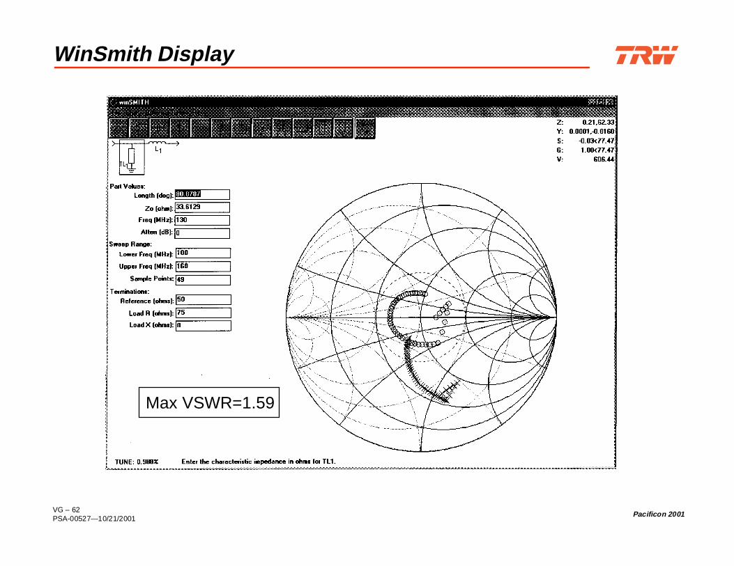
VG – 62PSA-00527—10/21/2001
Pacificon 2001
WinSmith Display
Max VSWR=1.59

VG – 63PSA-00527—10/21/2001
Pacificon 2001
ARRL Radio Designer
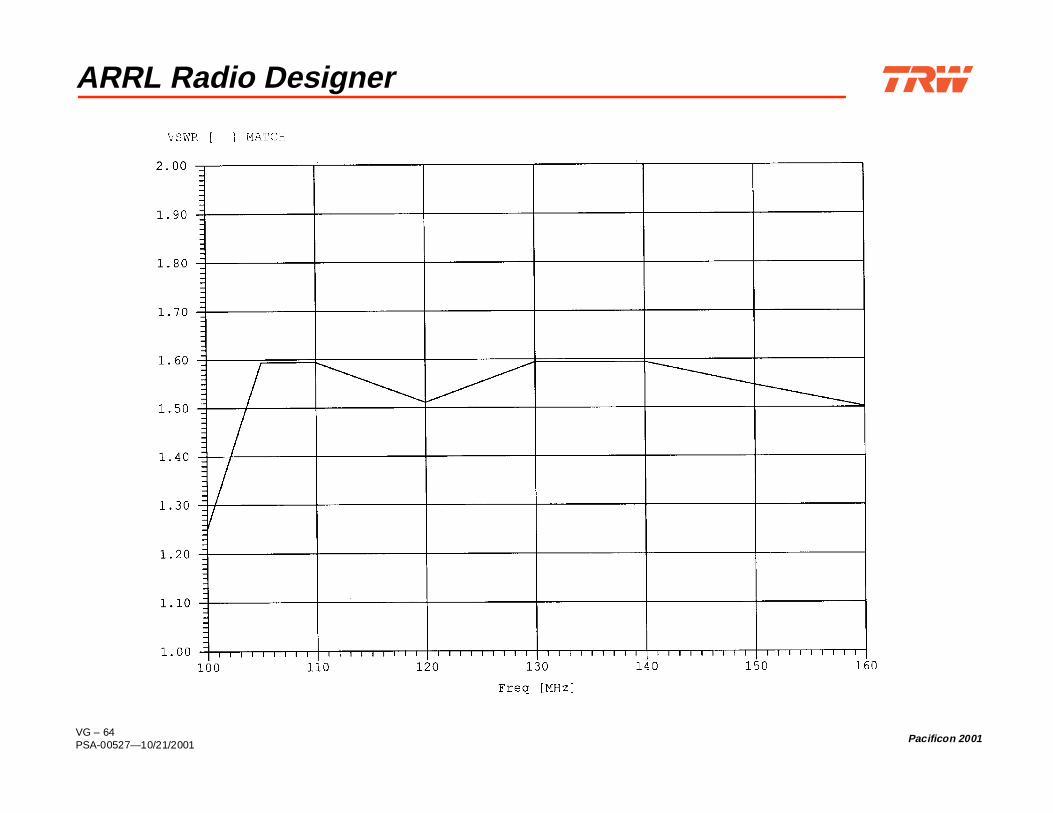
VG – 64PSA-00527—10/21/2001
Pacificon 2001
ARRL Radio Designer

VG – 65PSA-00527—10/21/2001
Pacificon 2001
Caron’s Example 11: Long Wire Receiving Antenna
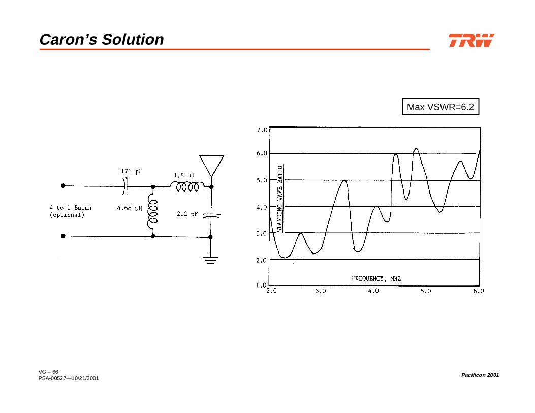
VG – 66PSA-00527—10/21/2001
Pacificon 2001
Caron’s Solution
Max VSWR=6.2

VG – 67PSA-00527—10/21/2001
Pacificon 2001
Caron’s Solution
Max VSWR=6.2

VG – 68PSA-00527—10/21/2001
Pacificon 2001
Eagleware’s Solution 1
Max VSWR=5.05

VG – 69PSA-00527—10/21/2001
Pacificon 2001
Eagleware’s Solution 2
Max VSWR=4.77

VG – 70PSA-00527—10/21/2001
Pacificon 2001
Eagleware’s Solution 3
Max VSWR=6.59

VG – 71PSA-00527—10/21/2001
Pacificon 2001
Eagleware’s Solution 4: Fano Limit
Max VSWR=3.42

VG – 72PSA-00527—10/21/2001
Pacificon 2001
GM3HAT 4-Band Dipole of Delight

VG – 73PSA-00527—10/21/2001
Pacificon 2001
GM3HAT Feedpoint ImpedanceAt Five Harmonic Frequencies
VSWR=11.02
VSWR=1.62

VG – 74PSA-00527—10/21/2001
Pacificon 2001
K6OIK 80m Suboctave Band Matching Network
150Ω89°@ 3.5 MHz
5.9 µH18.8 µH
25Ω91°@ 3.5 MHz
Zant

VG – 75PSA-00527—10/21/2001
Pacificon 2001
K6OIK’s Multiband Match Performance
VSWR=1.46

VG – 76PSA-00527—10/21/2001
Pacificon 2001
Software for Smith Charting and Network Design
Smith Chart Analysis & Display MicroSmith 2.3, ARRL, 1992, $39
A primitive DOS program.
winSMITH 2.0, Noble Publishing, 1995, $79Written by Eagleware. Easy to use. Restricted to ladder networks.Doesn’t have series stubs. Lacks an optimizer.
Matching Network Optimization & Synthesis ARRL Radio Designer 1.5, ARRL, 1995, $150
No longer sold. ARD’s optimizer works with Serenade netlists andhandles more variables than Serenade SV’s optimizer.
Serenade SV (student version), Ansoft, 2000, $0 (free)Download (about 20 Mbytes) from:http://www.ansoft.com/about/academics/sersv/index.cfm
Advanced Automated Smith Chart 3.0, Artech House, 1998, $395 =MATCH=, Eagleware, $699 (requires GENESYS Basic, $1997) Harmonica Linear Design Suite, Ansoft, 2000, $6900

VG – 77PSA-00527—10/21/2001
Pacificon 2001
References: Articles
Robert L. Thomas, “Broadband Impedance Matching in High-QNetworks,” EDN, pp. 62–69, December 20, 1973.
Neal C. Silence, “The Smith Chart and Its Usage in RF Design,”RF Design, pp. 85–88, April 1992.
Thomas R. Cuthbert, Jr., “Broadband Impedance Matching Methods,”RF Design, pp. 64–91, August 1994.
Thomas R. Cuthbert, Jr., “Broadband Impedance Matching - Fast andSimple,” RF Design, pp. 38–50, November 1994.
William E. Sabin, “Broadband HF Matching with ARRL RadioDesigner,” QST, pp. 33–36, August 1995.
William E. Sabin, “ARRL Radio Designer and the Circles Utility, Part 1:Smith Chart Basics,” QEX, pp. 3–9, Sept/Oct 1998.
William E. Sabin, “ARRL Radio Designer and the Circles Utility, Part 2:Small-Signal Amplifier Design,” QEX, pp. 3–11, Nov/Dec 1998.
VG – 78PSA-00527—10/21/2001
Pacificon 2001
References: Articles (Cont’d)
Steve Sparks, “A Practical Amateur Application of the Smith Chart,”Communications Quarterly, pp. 102–106, Summer 1999.
This article contains serious Smith charting errors. See the comments by GarryShapiro, NI6T, Communications Quarterly, p. 3, Fall 1999.
K.C. Chan and A. Harter, “Impedance Matching and the Smith Chart –The Fundamentals,” RF Design, pp. 52–66, July 2000.

VG – 79PSA-00527—10/21/2001
Pacificon 2001
References: Books
Robert A. Chipman, Transmission Lines, Schaum Outline Series,McGraw-Hill, 1968.
Basic, mathematical. A classic, but out-of-print.
Robert L. Thomas, A Practical Introduction to Impedance Matching,Artech House, 1976, ISBN 0890060509.
Intermediate, mathematical. A nice treatment of 4-element networks for widebandmatching.
Pieter L. D. Abrie, The Design of Impedance-Matching Networks forRadio-Frequency and Microwave Amplifiers, Artech House, 1985,ISBN 0890061726.
Advanced, mathematical.
Wilfred Caron, Antenna Impedance Matching, ARRL, 1989,ISBN 0872592200.
Intermediate, non-mathematical. Caron illustrates manual Smith chart methods attheir best, but which nonetheless have been completely replaced by computer-aided network design.
Brian C. Wadell, Transmission Line Design Handbook, Artech House,1991, ISBN 0890064369.
Analysis and formulas for many transmission lines. Comparable to M.A.R. Gunstonor K.C. Gupta, et al., below.

VG – 80PSA-00527—10/21/2001
Pacificon 2001
References: Books (Cont’d)
Phillip H. Smith, Electronic Applications of the Smith Chart inWaveguide Circuit, and Component Analysis, 2nd edition, NoblePublishing, 1995, ISBN 1884932398.
Originally published by McGraw-Hill, 1969, and reprinted by Krieger, 1983.Intermediate, mathematical.
K.C. Gupta, R. Garg, I. Bahl, and P. Bhartia, Microstrip Lines andSlotlines, 2nd ed., Artech House, 1996, ISBN 089006766X.
Analysis and formulas for many transmission lines.
M.A.R. Gunston, Microwave Transmission-Line Impedance Data,Noble Publishing, 1997, ISBN 1884932576.
Originally published by Van Nostrand Reinhold, 1972. Analysis and formulasfor many transmission lines. Comparable to B. Wadell above.
ARRL Antenna Book, 18th edition, chapters 24-28, ARRL, 1997,ISBN 0872596133.
Elementary, non-mathematical.
M. Walter Maxwell, W2DU, Reflections II: Transmission Lines andAntennas, 2nd ed., Worldradio Books, 2001, ISBN 0970520603.
A non-mathematical treatment of transmission lines and matching thatexamines and corrects common misunderstandings.

VG – 81PSA-00527—10/21/2001
Pacificon 2001
References: Application Notes, Videos, and Web Sites
Application Notes Times Microwave’s Complete Coaxial Cable Catalog & Handbook
Download from:http://www.timesmicrowave.com/products/military/TL14/TL14.htm
Videos Glenn Parker, Introduction to the Smith Chart, Noble Publishing,
1996. 50 minutes, $99.
Useful Web Sites http://www.timesmicrowave.com/calculators/index.htm http://www.sss-mag.com/smith.html http://www.ee.surrey.ac.uk/Personal/D.Jefferies/smith.html http://www.scott-inc.com/html/smith.htm
This Presentation is at http://www.fars.k6ya.org/docs/smithchart.html